Loading ...
Loading ...
Loading ...
30
INSTALLATION
Check the appliance is electrically safe and gas sound when you have nished.
ArtNo.090-0024 - 90 induction door clearances
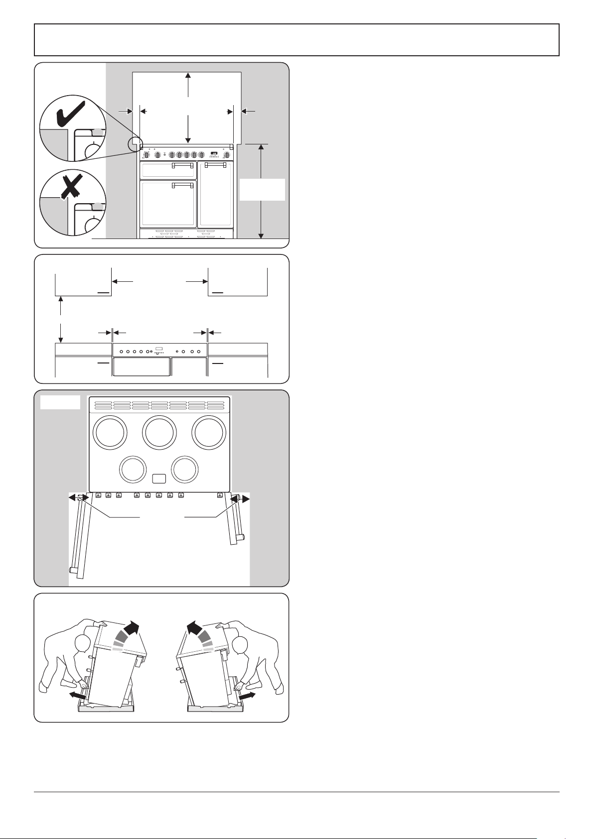
130 mm min
ArtNo.090-0028 - 90 cooker min spacing GENERIC
75 mm
min
75 mm
min
650 mm
min
905 mm min
930 mm max
ArtNo.090-0017 - 90 6BC min positions above cooker
410 mm min.
900 mm min.*
10 mm10 mm
**
Positioning the Cooker
Fig. 7.1 and Fig. 7.2 show the minimum recommended
distance from the cooker to nearby surfaces.
Where the appliance is installed next to cabinetry, the
cabinet material must be capable of withstanding 70°C. If
this appliance is installed near vinyl wrapped surfaces, use an
installation kit available from the vinyl-wrap supplier. Falcon
cannot accept any responsibility for damage caused due to
installation into cabinets with low temperature tolerances.
The cooker should not be placed on a base.
The hotplate surround should be level with, or above,
any adjacent work surface. A gap of 75 mm should be left
between each side of the cooker ABOVE the hotplate level
and any adjacent vertical surface.
For non-combustible surfaces (such as unpainted metal or
ceramic tiles), this can be reduced to 25 mm.
A minimum space of 650 mm is required between the top of
the hob and a horizontal combustible surface.
*Any cookerhood should be installed in accordance with the
hood manufacturer’s instructions.
**Any splashback must be tted in accordance with the
manufacturers instructions. Allowance should be made for the
additional height of the ue trim, which is tted to the cooker
hob.
Surfaces of furniture and walls at the sides and rear of the
appliance should be heat, splash and steam resistant. Certain
types of vinyl or laminate kitchen furniture are particularly
prone to heat damage and discolouration. We cannot accept
responsibility for damage caused by normal use of the
cooker to any material that de-laminates or discolours at
temperatures less than 65 °C above room temperature.
We recommend a gap of 920 mm between units for
induction cookers to allow for moving the cooker. Do not
box the cooker in – it must be possible to move the cooker in
and out for cleaning and servicing.
If the cooker is near a corner of the kitchen, a clearance of
130 mm is required to allow the oven doors to open (Fig. 7.3).
The actual opening of the doors is slightly less, but this allows
for some protection of your hand as you open the door.
Moving the Cooker
We recommend that two people manoeuvre the cooker.
Make sure that the oor covering is rmly xed, or removed,
to prevent it being disturbed when moving the cooker
around.
To help you, there are two levelling rollers at the back, and
two screw-down levelling feet at the front.
Remove the polystyrene base pack. From the front, tilt
the cooker backwards and remove the front half of the
polystyrene base (Fig. 7.4). Repeat from the back and remove
the rear half of the polystyrene base.
Fig. 7.1
Fig. 7.2
Fig. 7.3
Fig. 7.4
Loading ...
Loading ...
Loading ...