Loading ...
Loading ...
Loading ...
PAGE: 5 / 10
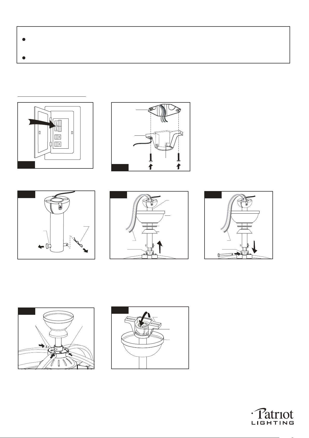
Installation Steps :
INSTALLATION INSTRUCTIONS
IMPORTANT:
BEFORE YOU BEGIN INSTALLING THE FAN, CAREFULLY READ ALL INFORMATION IN
SAVE ALL INSTRUCTIONS.
NOTE: The fan weight is 15.87 lbs (7.2 kg). Be sure the outlet box you are using is securely attached to the building
structure and can support the full weight of the fan. Failure to do so can result in serious injury.
Hanger Pin
Lock Pin
Remove the Lock Pin and take off
the Hanger Pin.
Fig.3
Loosen the collar screws out part way.
Insert the Downrod into the Collar.
Slide Hanger Pin through holes of
Collar and Downrod.
Tighten the two Collar Screws.
Slide Lock Pin into Hanger
Pin until it is locked into position.
Slide canopy, canopy cover (Making
Hang fan on hanger bracket, and rotate the downrod until the chip on
the hanger bracket snaps into the slot on the hanger ball.
Note: For slope ceiling installation, make sure the slot of hanger
ball and the chip of hanger bracket are toward the floor.
Slot
Chip
Hanger Bracket
Fig.7
Tighten the hanger bracket to the outlet
box with 2 mounting screws. (To reduce
the risk of fire, electric shock, or personal
injury, mount to the outlet box marked
"Acceptable for fan support" and use
mounting screws provided with the outlet
box.)
Note: For slope ceiling installation, make
sure that the chip of the hanger bracket
is toward the floor.
Fig.1
Turn OFF the electric circuit at the
main fuse or circuit breaker box.
Hanger
Bracket
Fig.2
Outlet Box
Chip
Fig.4
Motor Wires
Collar
Downrod
Canopy
Canopy Cover
Downrod Stand
Cover
THE SAFETY
INSTRUCTIONS AND INSTALLATION INSTRUCTIONS. IF IN DOUBT, CONSULT A QUALIFIED
ELECTRICIAN.
sure the smooth side of canopy cover
is facing downward.), and downrod
stand cover onto downrod, as shown;
then thread motor wires through
downrod.
191225
Fig.5
Motor Wires
Collar
Fig.6
Lock Pin
Collar
Screws
Loading ...
Loading ...
Loading ...