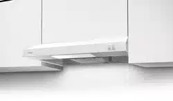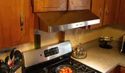
LEVE24SS200
LEVE30SS200
LEVE24WH200
LEVE30WH200
Installation Instructions
Use and Care Information
Instructions d'installation
Utilisez et d'entretien
Instrucciones de instalación
Información de uso y cuidado
Levante E

2
CONTENTS
Section Page
Important safety instructions 3
Range Hood dimensions 6
Installation height requirements 7
Parts 8
Tools needed 9
Choose Vertical or Horizontal Electrical Connection Knockout's
Choose Vertical or Horizontal Electrical Connection Knockout's 10
All ducted venting method
All ducted venting method 12
Ducted venting method options 13
Ducted - 7" round outlet 14
Ducted - 3 1/4" x 10" Rectangular Outlet on top
16
Ducted - 3 1/4" x 10" Rectangular Outlet rear
17
Non Ducted Recirculation Option
18
Choosing the Mounting Method
19
Mounting Range Hood on wall
20
Mounting Range Hood under the cabinet
24
Connecting electricity
26
Operating the controls
27
&DULQJIRU´OWHUV
28
Replacing lighting
30
Wiring diagram
31
Warranty
32

3
IMPORTANT SAFETY INSTRUCTIONS
READ AND SAVE THESE INSTRUCTIONS BEFORE YOU START
INSTALLING THIS RANGE HOOD
WARNING: - TO REDUCE THE RISK OF A RANGE TOP GREASE FIRE:
a) Never leave surface units unattended at high settings. Boilovers cause smoking and
greasy spillovers that may ignite. Heat oils slowly on low or medium setting.
E$OZD\VWXUQKRRG21ZKHQFRRNLQJDWKLJKKHDWRUZKHQµDPEHLQJIRRGLH&UHSHV
Suzette, Cherries Jubilee, Peppercorn Beef Flambé).
c) Clean ventilating fans frequently. Grease should not be allowed to accumulate on fan or
´OWHU
d) Use proper pan size. Always use cookware appropriate for the size of the surface element.
WARNING: - TO REDUCE THE RISK OF INJURY TO PERSONS IN THE EVENT OF A RANGE
TOP GREASE FIRE, OBSERVE THE FOLLOWING*:
D6027+(5)/$0(6ZLWKDFORVH´WWLQJOLGFRRNLHVKHHWRUPHWDOWUD\WKHQWXUQRIIWKH
EXUQHU%(&$5()8/7235(9(17%8516,IWKHµDPHVGRQRWJRRXWLPPHGLDWHO\
EVACUATE AND CALL THE FIRE DEPARTMENT.
b) NEVER PICK UP A FLAMING PAN - You may be burned.
c) DO NOT USE WATER, including wet dishcloths or towels - a violent steam explosion will
result.
d) Use an extinguisher ONLY if:
1. You know you have a Class ABC extinguisher, and you already know how to operate
it.
7KH´UHLVVPDOODQGFRQWDLQHGLQWKHDUHDZKHUHLWVWDUWHG
7KH´UHGHSDUWPHQWLVEHLQJFDOOHG
<RXFDQ´JKWWKH´UHZLWK\RXUEDFNWRDQH[LW
* Based on "Kitchen Firesafety Tips" published by NFPA
WARNING - TO REDUCE THE RISK OF FIRE OR ELECTRIC SHOCK, do not use this fan with
any solid-state speed control device.
WARNING - TO REDUCE THE RISK OF FIRE, ELECTRICAL SHOCK, OR INJURY TO PERSONS,
OBSERVE THE FOLLOWING:
1. Use this unit only in the manner intended by the manufacturer. If you have any questions,
contact the manufacturer.
2. Before servicing or cleaning unit, switch power off at service panel and lock the service
disconnecting means to prevent power from being switched on accidentally. When the
service disconnecting means cannot be locked, securely fasten a prominent warning
device, such as a tag, to the service panel.
CAUTION: For General Ventilating Use Only. Do Not Use To Exhaust Hazardous or Explo-
sive Materials and Vapors.
WARNING - TO REDUCE THE RISK OF FIRE, ELECTRICAL SHOCK, OR INJURY TO PERSONS,
OBSERVE THE FOLLOWING:
1. ,QVWDOODWLRQ:RUN$QG(OHFWULFDO:LULQJ0XVW%H'RQH%\4XDOL´HG3HUVRQV,Q$FFRU-
dance With All Applicable Codes And Standards, Including Fire-Rated Construction.
2. 6XI´FLHQWDLULVQHHGHGIRUSURSHUFRPEXVWLRQDQGH[KDXVWLQJRIJDVHVWKURXJKWKH
µXHFKLPQH\RIIXHOEXUQLQJHTXLSPHQWWRSUHYHQWEDFNGUDIWLQJ)ROORZWKHKHDWLQJ
equipment manufacturer's guideline and safety standards such as those published by
WKH1DWLRQDO)LUH3URWHFWLRQ$VVRFLDWLRQ1)3$DQGWKH$PHULFDQ6RFLHW\IRU+HDWLQJ
5HIULJHUDWLRQDQG$LU&RQGLWLRQLQJ(QJLQHHUV$6+5$(DQGWKHORFDOFRGHDXWKRULWLHV
4
ALL WALL AND FLOOR OPENINGS WHERE THE RANGE HOOD IS INSTALLED
MUST BE SEALED.
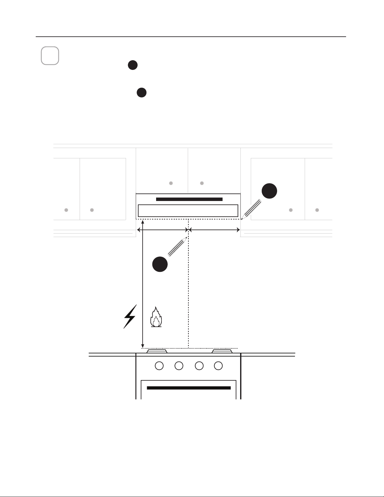
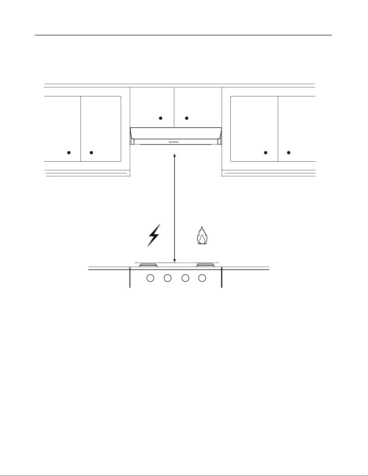
This Range Hood requires at least 24" of clearance between the bottom of the Range
Hood and the cooking surface or countertop. This hood has been approved by UL at this
distance from the cooktop.
This minimum clearance may be higher depending on local building codes. For gas cooktops
and combination ranges, a minimum of 30" is recommended and may be required.
Overhead cabinets on both sides of this unit must be a minimum of 18" above the cooking
surface or countertop. Consult the cooktop or range installation instructions given by the
manufacturer before making any cutouts.
MOBILE HOME INSTALLATION The installation of this Range Hood must conform to the
Manufactured Home Construction and Safety Standards, Title 24 CFR, Part 3280 (formerly
Federal Standard for Mobile Home Construction and Safety, Title 24, HUD, Part 280). See
Electrical Requirements"
• Venting system MUST terminate outside the home.
• DO NOT terminate the ductwork in an attic or other enclosed space.
• DO NOT use 4" laundry-type wall caps.
• Flexible-type ductwork is not recommended.
• DO NOTREVWUXFWWKHµRZRIFRPEXVWLRQDQGYHQWLODWLRQDLU
)DLOXUHWRIROORZYHQWLQJUHTXLUHPHQWVPD\UHVXOWLQD´UH
WARNING
!
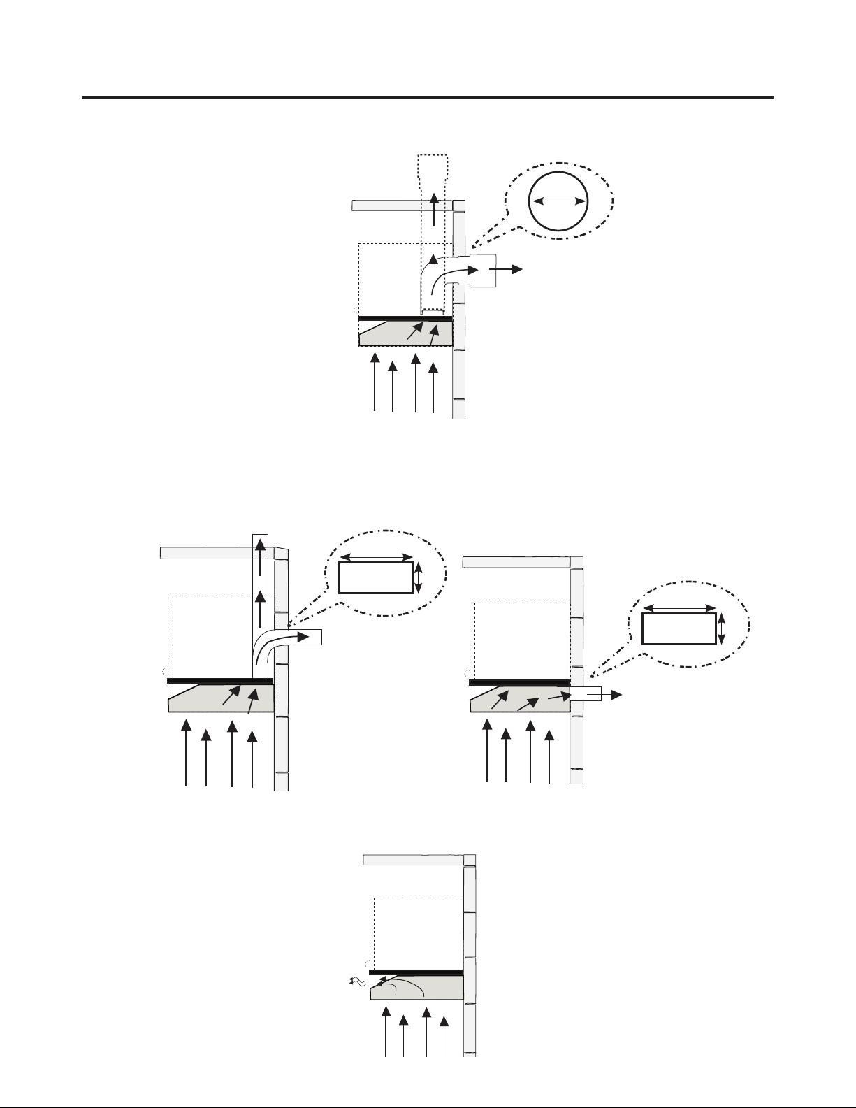
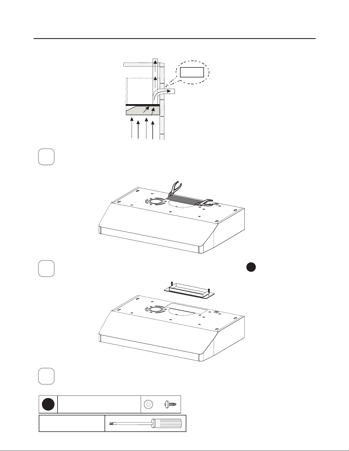
VENTING REQUIREMENTS
Determine which venting method is best for your application. Ductwork can extend either
through the wall or the roof.
The length of the ductwork and the number of elbows should be kept to a minimum to
SURYLGHHI´FLHQWSHUIRUPDQFH7KHVL]HRIWKHGXFWZRUNVKRXOGEHXQLIRUP'RQRWLQVWDOO
two elbows together. Use duct tape to seal all joints in the ductwork system. Use caulking
WRVHDOH[WHULRUZDOORUµRRURSHQLQJDURXQGWKHFDS
Flexible ductwork is not recommended. Flexible ductwork creates back pressure and air
turbulence that greatly reduces performance.
0DNHVXUHWKHUHLVSURSHUFOHDUDQFHZLWKLQWKHZDOORUµRRUIRUH[KDXVWGXFWEHIRUHPDNLQJ
cutouts. Do not cut a joist or stud unless absolutely necessary. If a joist or stud must be cut,
then a supporting frame must be constructed.
WARNING - To Reduce The Risk Of Fire, Use Only Metal Ductwork.
&$87,217RUHGXFHULVNRI´UHDQGWRSURSHUO\H[KDXVWDLUEHVXUHWRGXFWDLURXWVLGH
– Do not vent exhaust air into spaces within walls or ceilings or into attics, crawl spaces,
or garages.
Cold Weather installations
$QDGGLWLRQDOEDFNGUDIWGDPSHUVKRXOGEHLQVWDOOHGWRPLQLPL]HEDFNZDUGFROGDLUµRZDQGDQRQPH-
tallic thermal break should be installed to minimize conduction of outside temperatures as part of the
vent system. The damper should be on the cold air side of the thermal break. The break should be as
close as possible to where the vent system enters the heated portion of the house.
3. When cutting or drilling into wall or ceiling, do not damage electrical wiring and other
hidden utilities.
4. Ducted fans must always be vented to the outdoors.
5
ELECTRICAL REQUIREMENTS
A 120 volt, 60 Hz AC-only electrical supply is required on a separate 15 amp fused circuit.
A time-delay fuse or circuit breaker is recommended. The fuse must be sized per local
FRGHVLQDFFRUGDQFHZLWKWKHHOHFWULFDOUDWLQJRIWKLVXQLWDVVSHFL´HGRQWKHVHULDOUDWLQJ
SODWHORFDWHGLQVLGHWKHXQLWQHDUWKH´HOGZLULQJFRPSDUWPHQW
ELECTRICAL INSTALLATION WITH WIRING BOX
THIS UNIT MUST BE CONNECTED WITH COPPER WIRE ONLY. Wire sizes must conform
WRWKHUHTXLUHPHQWVRIWKH1DWLRQDO(OHFWULFDO&RGH$16,1)3$ODWHVWHGLWLRQDQGDOO
local codes and ordinances. Wire size and connections must conform with the rating of
the appliance. Copies of the standard listed above may be obtained from:
National Fire Protection Association
Batterymarch Park
Quincy, Massachusetts 02269
This appliance should be connected directly to the fused disconnect (or circuit breaker)
WKURXJKµH[LEOHDUPRUHGRUQRQPHWDOOLFVKHDWKHGFRSSHUFDEOH$OORZVRPHVODFNLQ
the cable so the appliance can be moved if servicing is ever necessary. A UL Listed,
FRQGXLWFRQQHFWRUPXVWEHSURYLGHGDWHDFKHQGRIWKHSRZHUVXSSO\FDEOHDW
the appliance and at the junction box).
:KHQPDNLQJWKHHOHFWULFDOFRQQHFWLRQFXWDKROHLQWKHZDOO$KROHFXWWKURXJK
wood must be sanded until smooth. A hole through metal must have a grommet.
• Electrical ground is required on this Range Hood.
• If cold water pipe is interrupted by plastic, nonmetallic gaskets or other
materials, DO NOT use for grounding.
• DO NOT ground to a gas pipe.
• DO NOT have a fuse in the neutral or grounding circuit. A fuse in the neutral
or grounding circuit could result in electrical shock.
&KHFNZLWKDTXDOL´HGHOHFWULFLDQLI\RXDUHLQGRXEWDVWRZKHWKHUWKH5DQJH
Hood is properly grounded.
)DLOXUHWRIROORZHOHFWULFDOUHTXLUHPHQWVPD\UHVXOWLQD´UH
WARNING
6
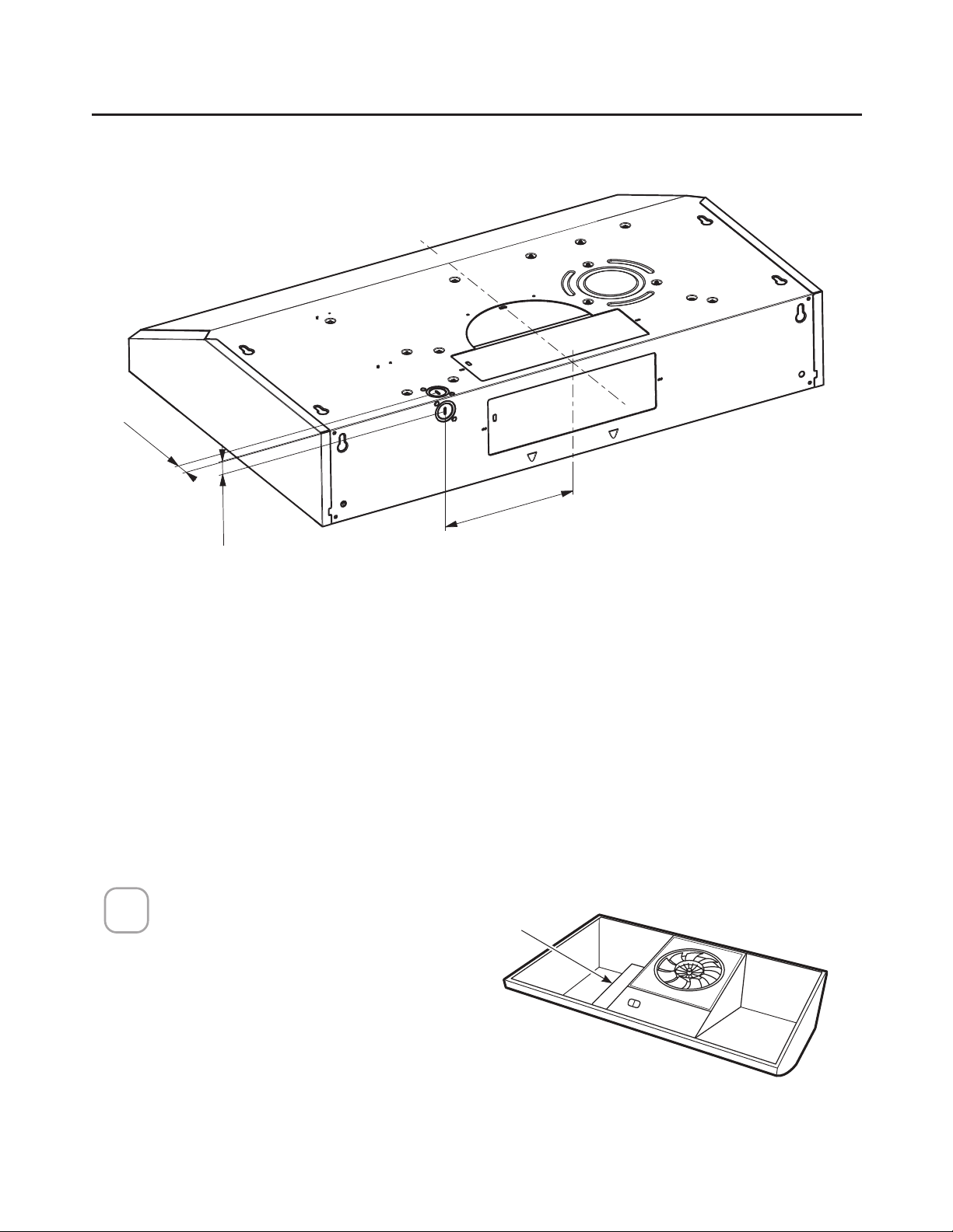
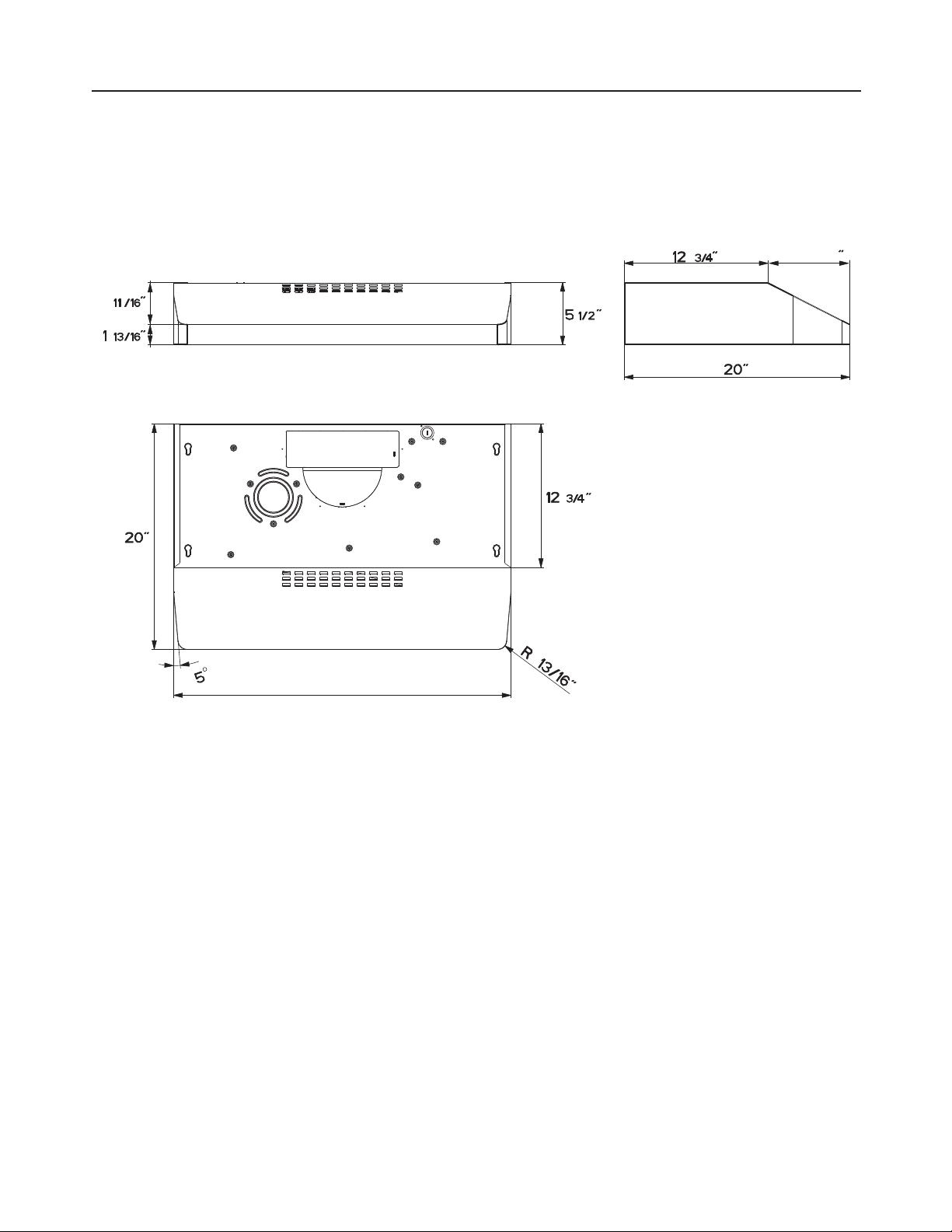
RANGE HOOD DIMENSIONS
7 1/4
3
23 15/16” - 29 15/16” - 35 15/16”
7
MIN. 24" OVER ELECTRIC / MIN. 30" OVER GAS
Min.24” Min.30”
INSTALLATION HEIGHT REQUIREMENTS
8
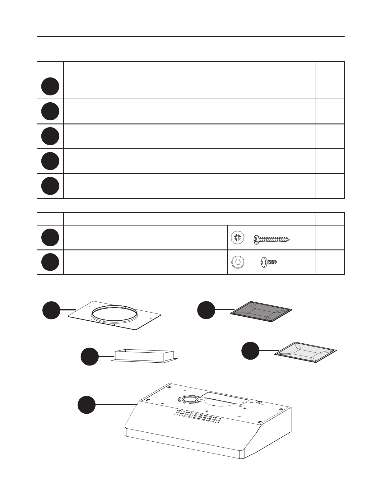
PARTS
REF. PART
A
Hood body – Includes Controls, Light, Filters, Blower 1
B
Damper ([)1
C
7" Round Flange
1
X
&KDUFRDO´OWHU
1
Y
*UHDVH´OWHU
1
REF
PART
E
3R]L6FUHZV[
4
F
7RU[6FUHZV[
4
PARTS INCLUDED
B
C
A
X
Y
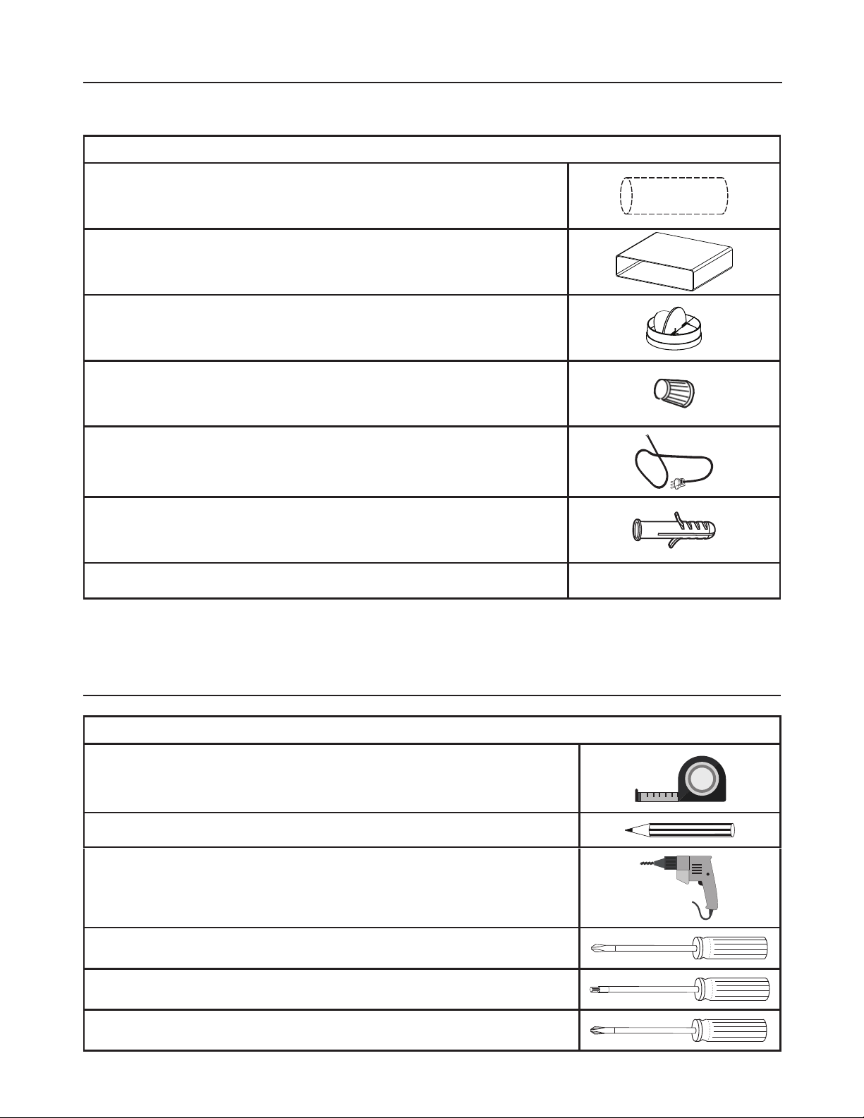
9
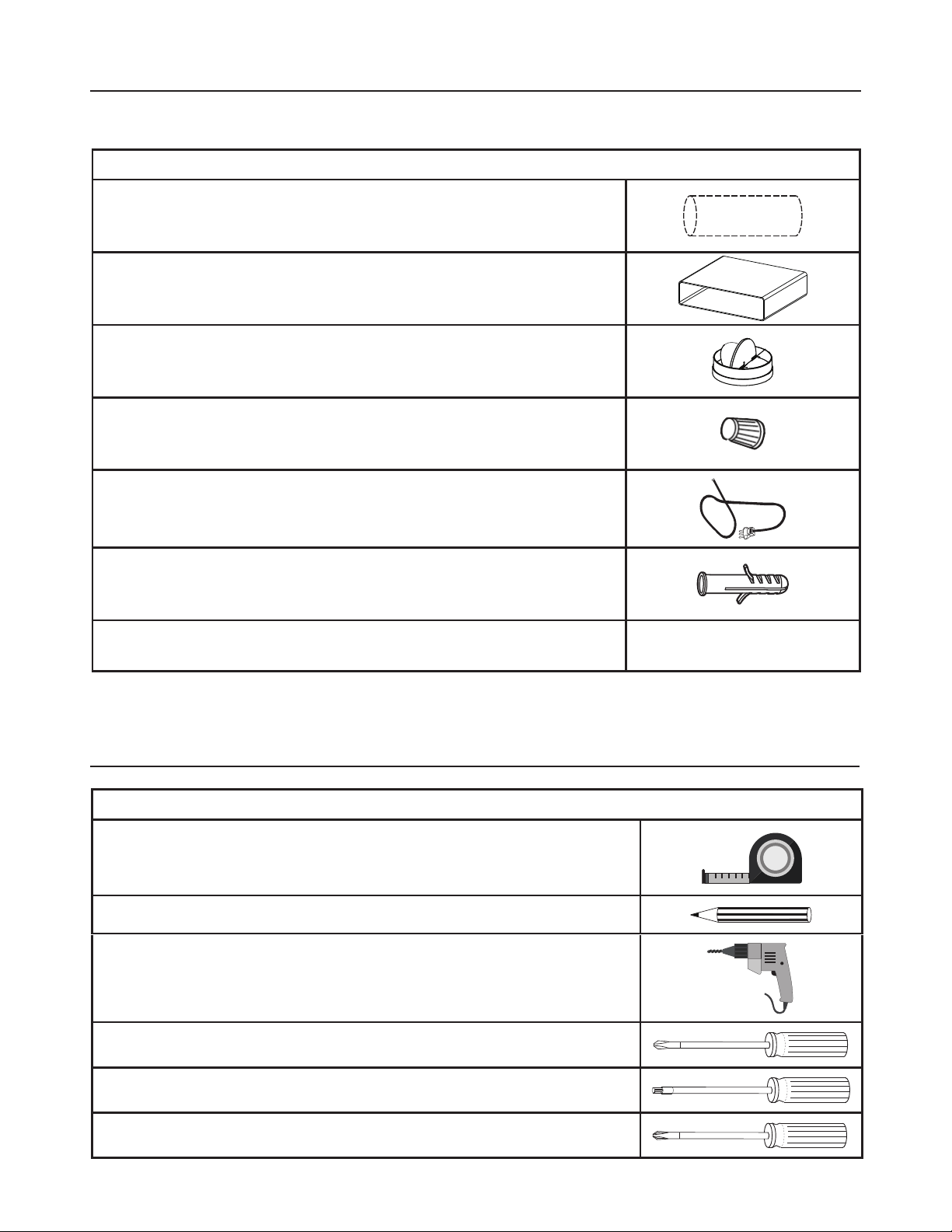
PARTS NEEDED
3$576FRQW
PART
7" Round Metal Ductwork
[5HFWDQJXODU'XFWZRUN
7" Damper
Wire connectors.
Power Supply Cable.
Drywall plugs or other suitable wall fasteners based on
your installation.
:DOO&DS5RRI&DS1HHGVWREHSXUFKDVHGVHSDUDWHO\
TOOLS NEEDED
TOOL
Tape Measure
Pencil
(OHFWULF'ULOOZLWK'ULOO%LW
Phillips Screwdriver
Torx Screwdriver
Pozi Screwdriver
10
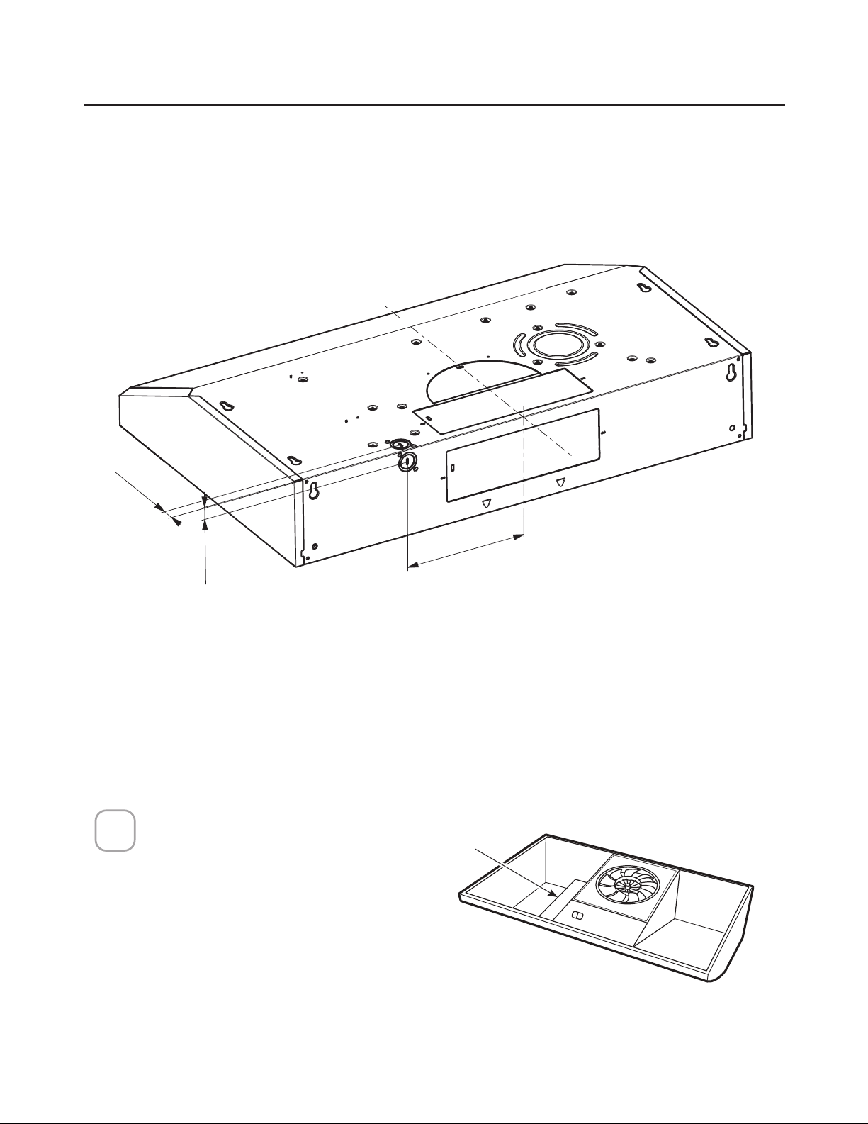
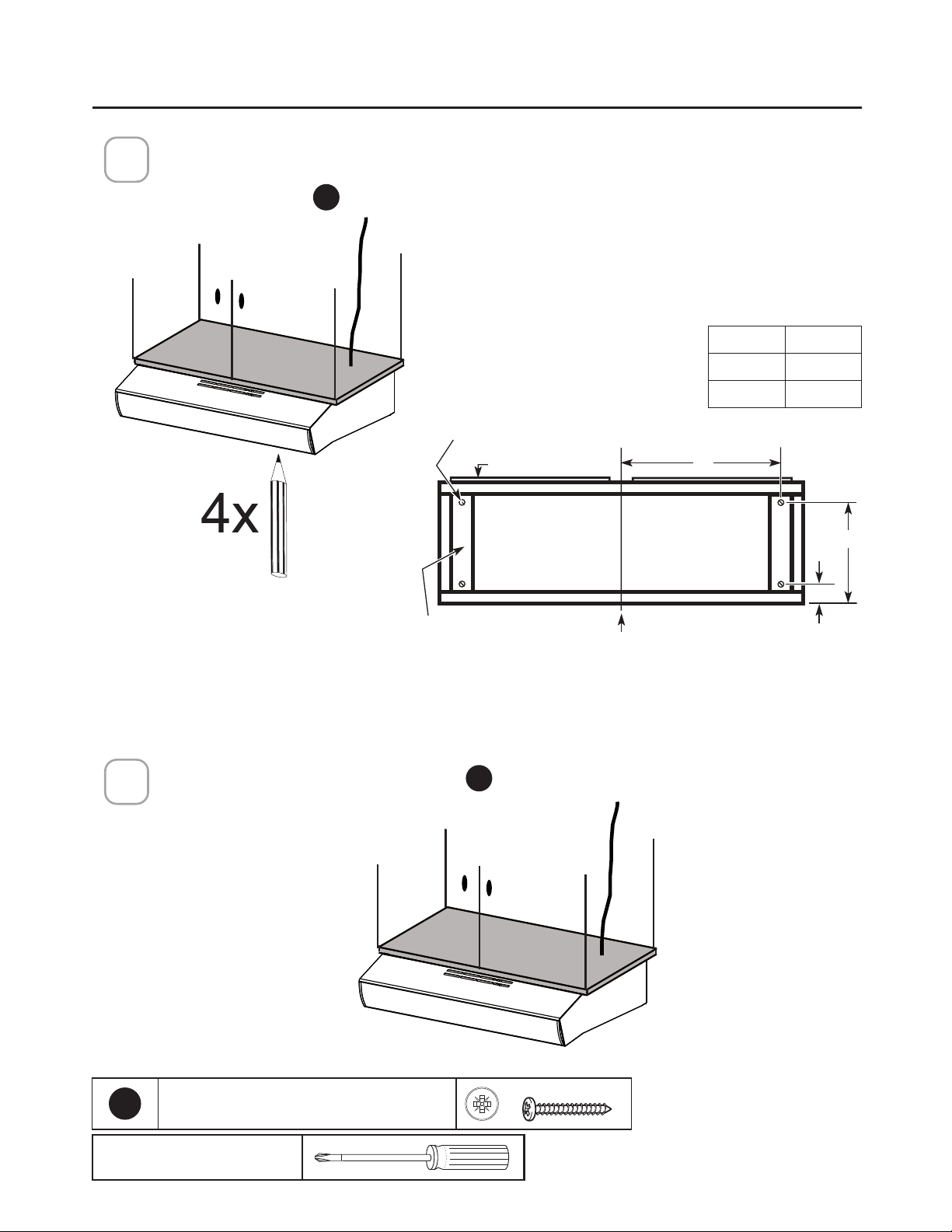
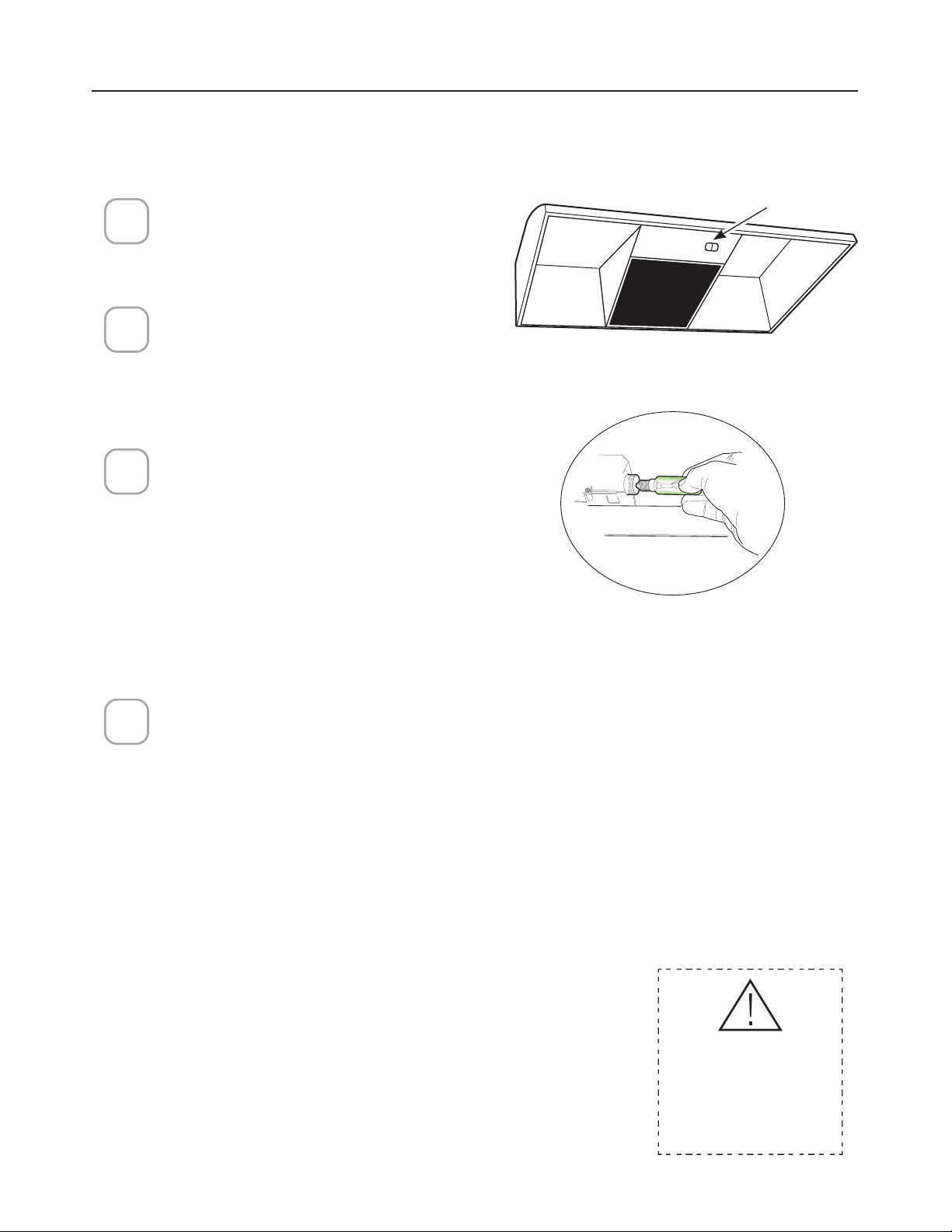
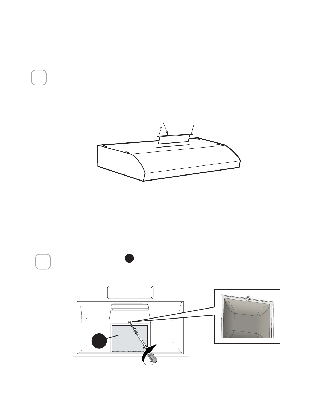
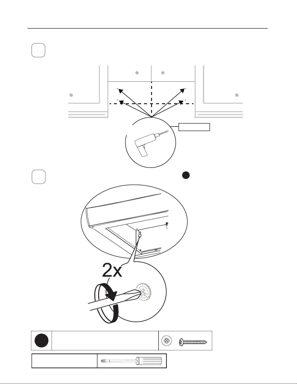
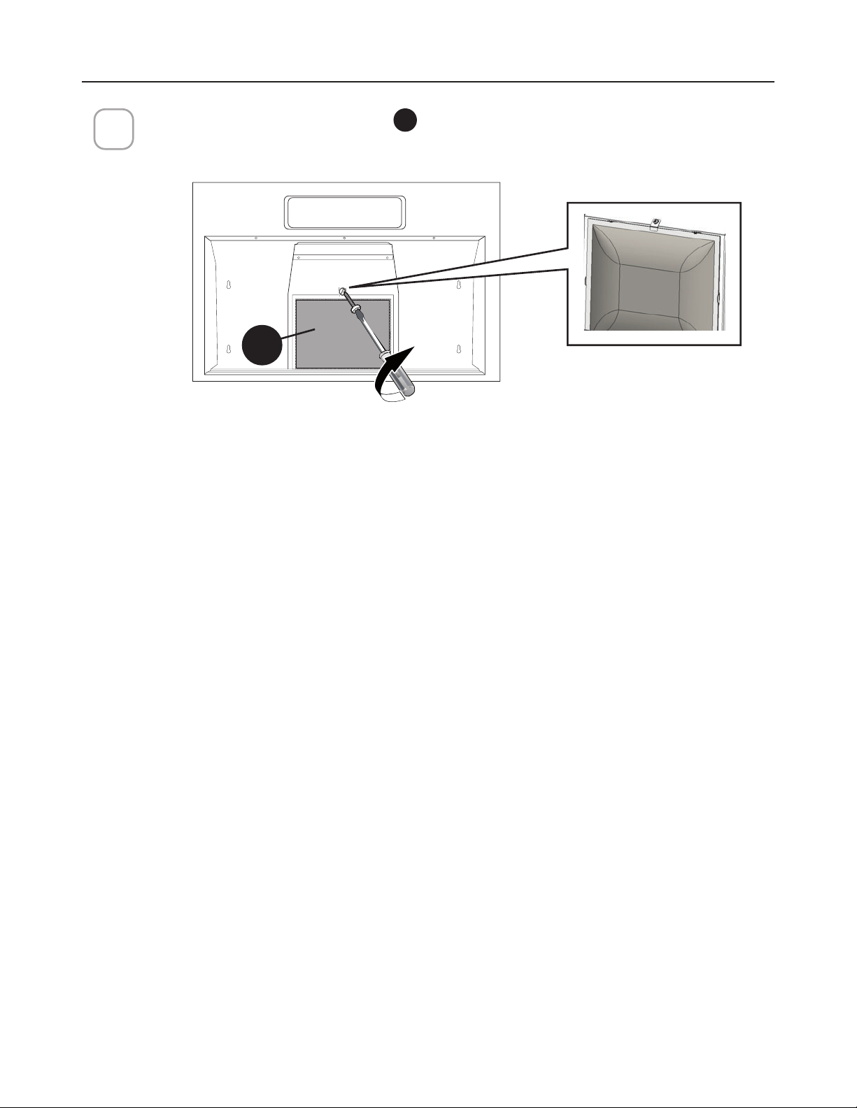
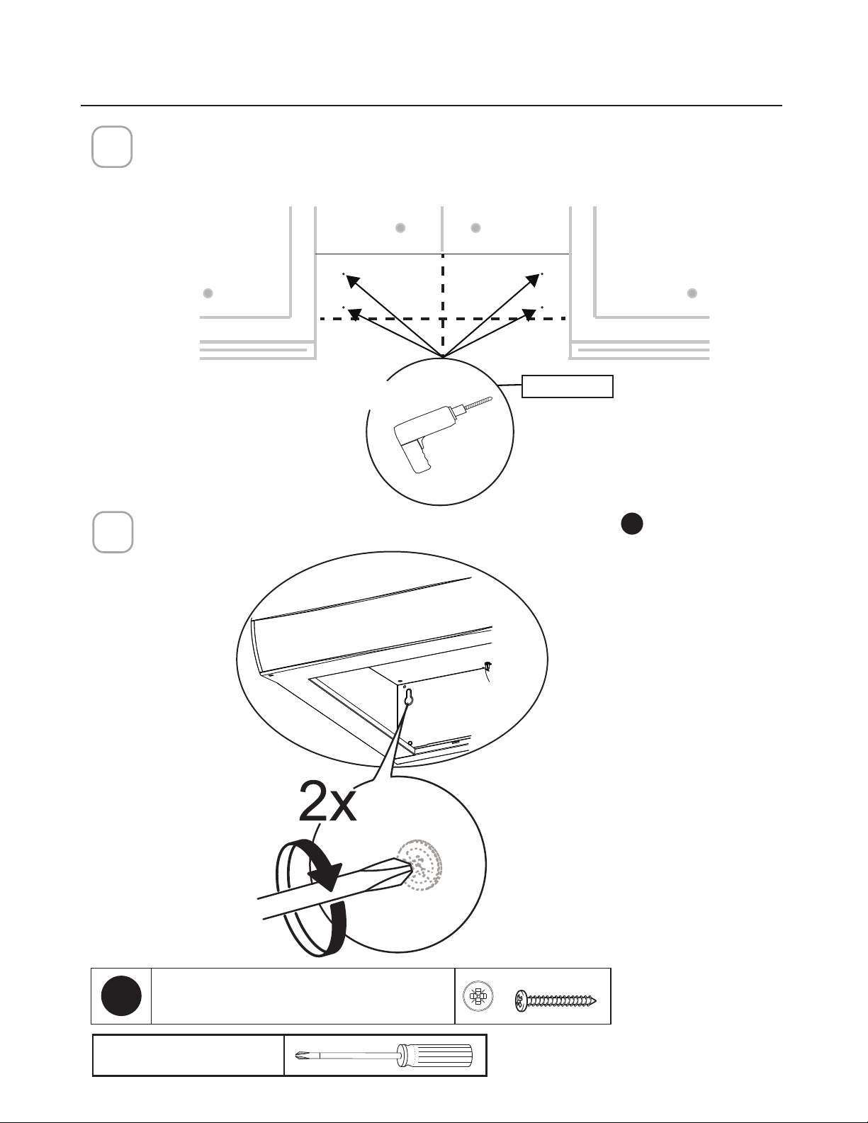
Preparing the hood for electrical knockouts
7" 1/2
13/16"
13/16"
CHOOSE VERTICAL OR HORIZONTAL
ELECTRICAL CONNECTION KNOCKOUT'S
PREPARE FOR
ELECTRICAL – REMOVE
HOOD JUNCTION BOX
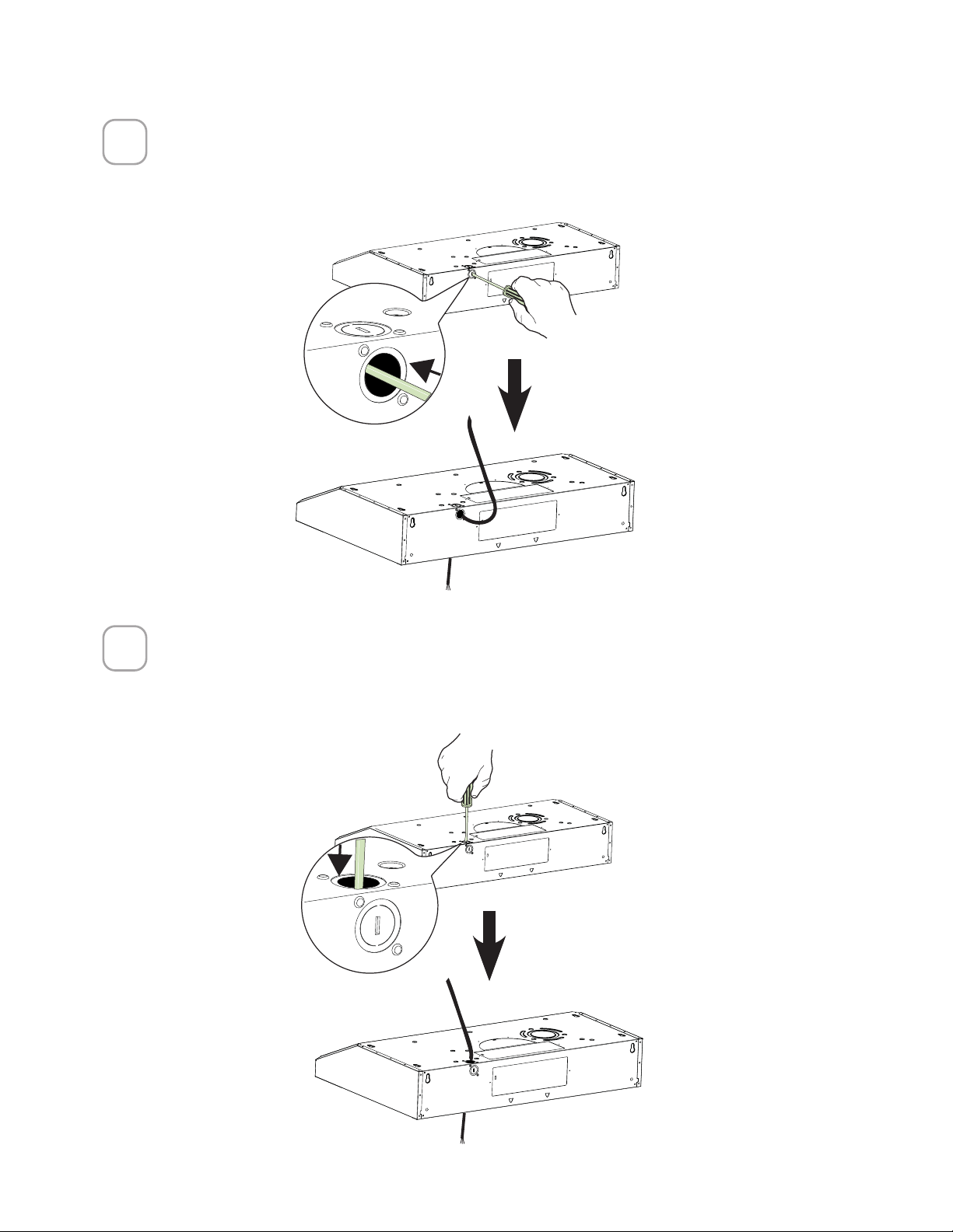
Remove the hood
junction box from inside
the hood. Set the cover
and its mounting screws
aside.
1
+RRG
-XQFWLRQ
%R[
Hood
Junction
Box

11
5HDU+ROH+RUL]RQWDO
Choose the rear hole for the electric connection and break with a screwdriver or other
tool.
During the installation thread Power Supply Cable through this hole.
2
7RS+ROH9HUWLFDO
Choose the top hole for the electric connection and break with a screwdriver or
other tool.
During the installation thread Power Supply Cable through this hole.
3
12
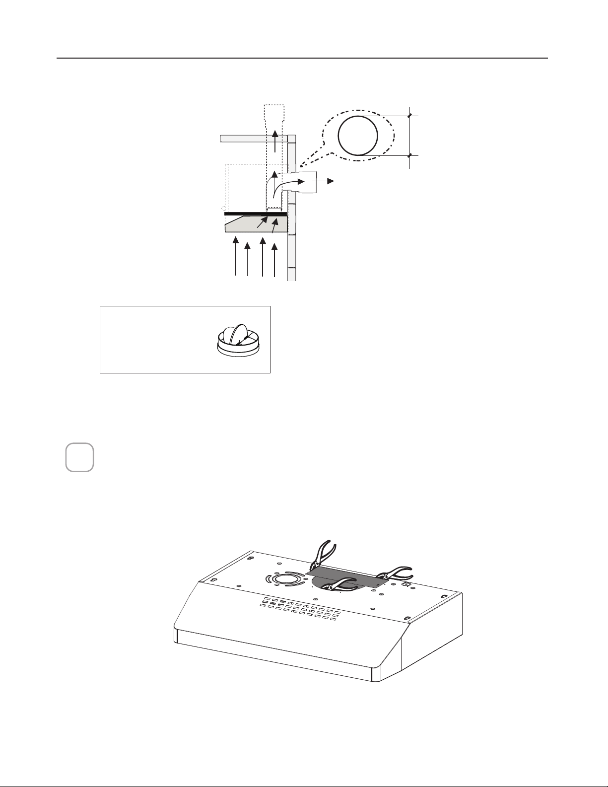
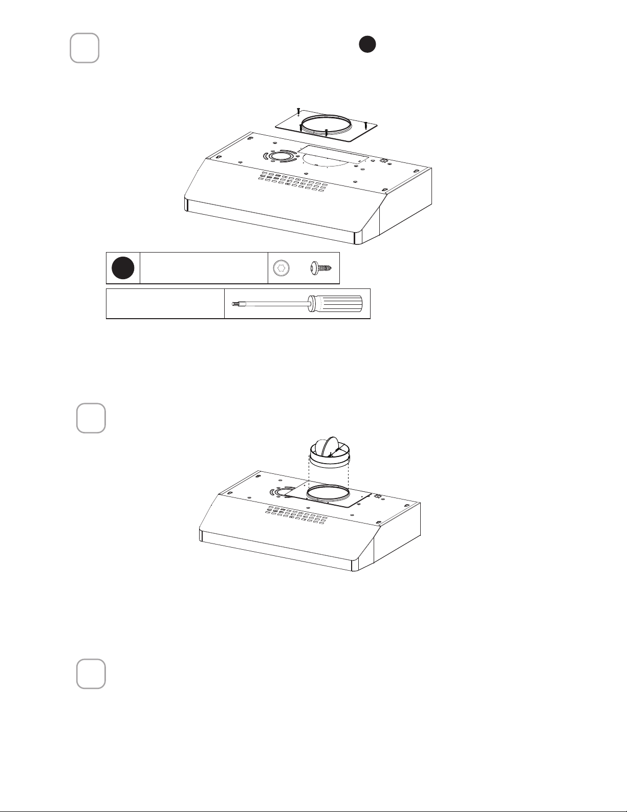
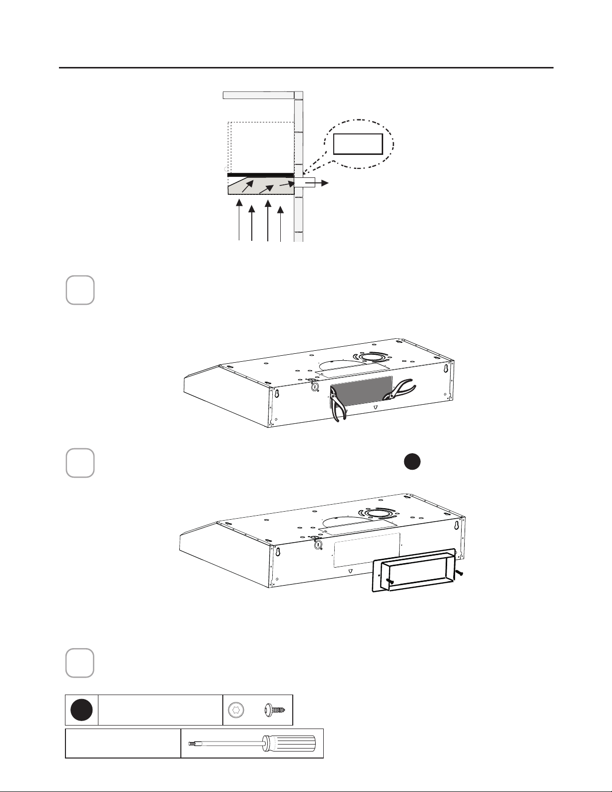
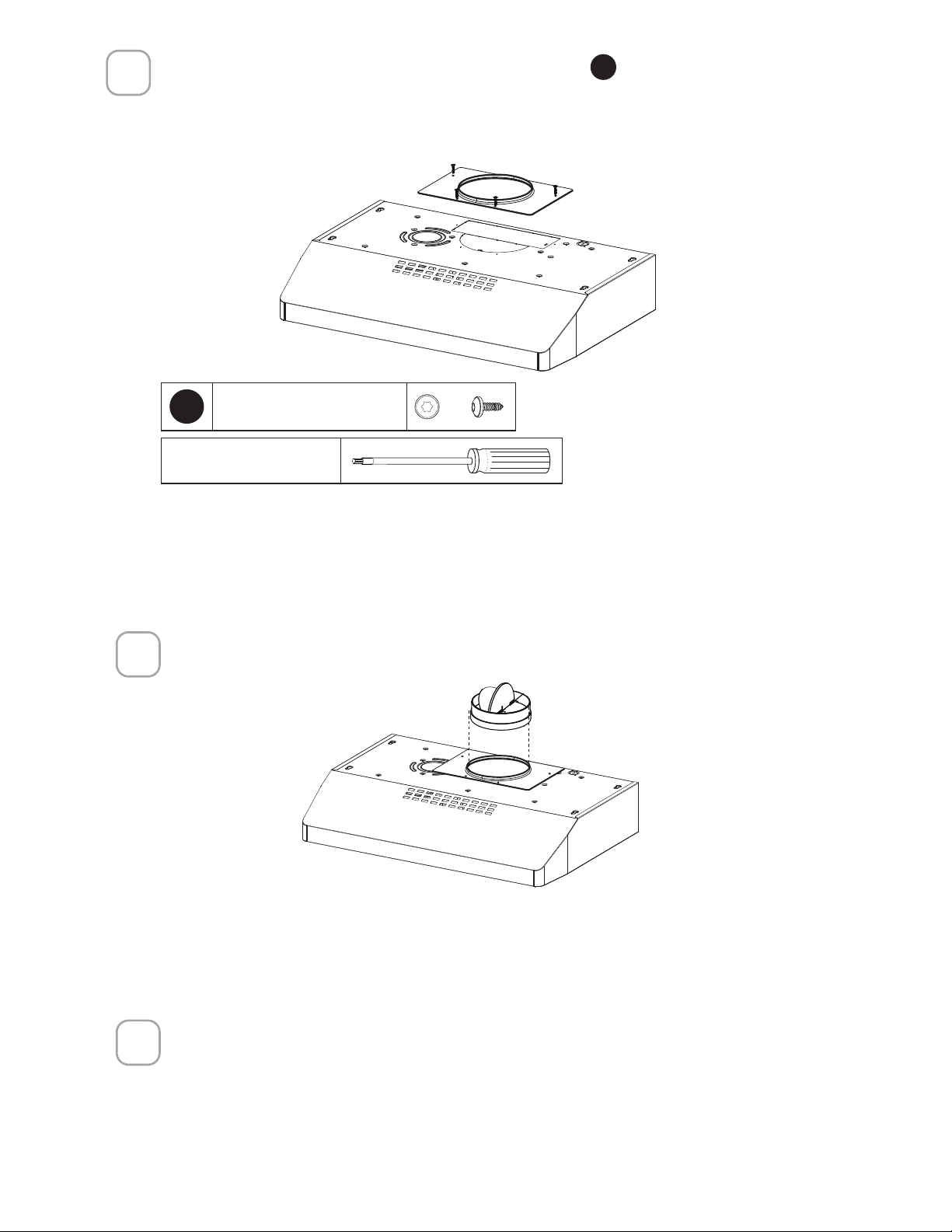
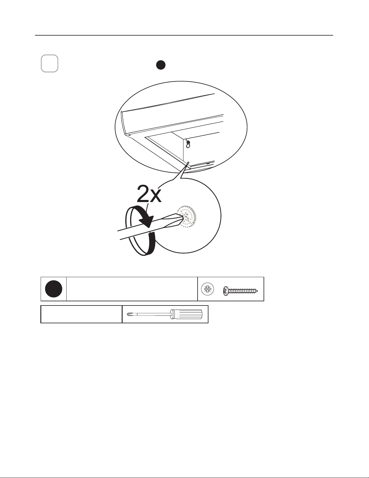
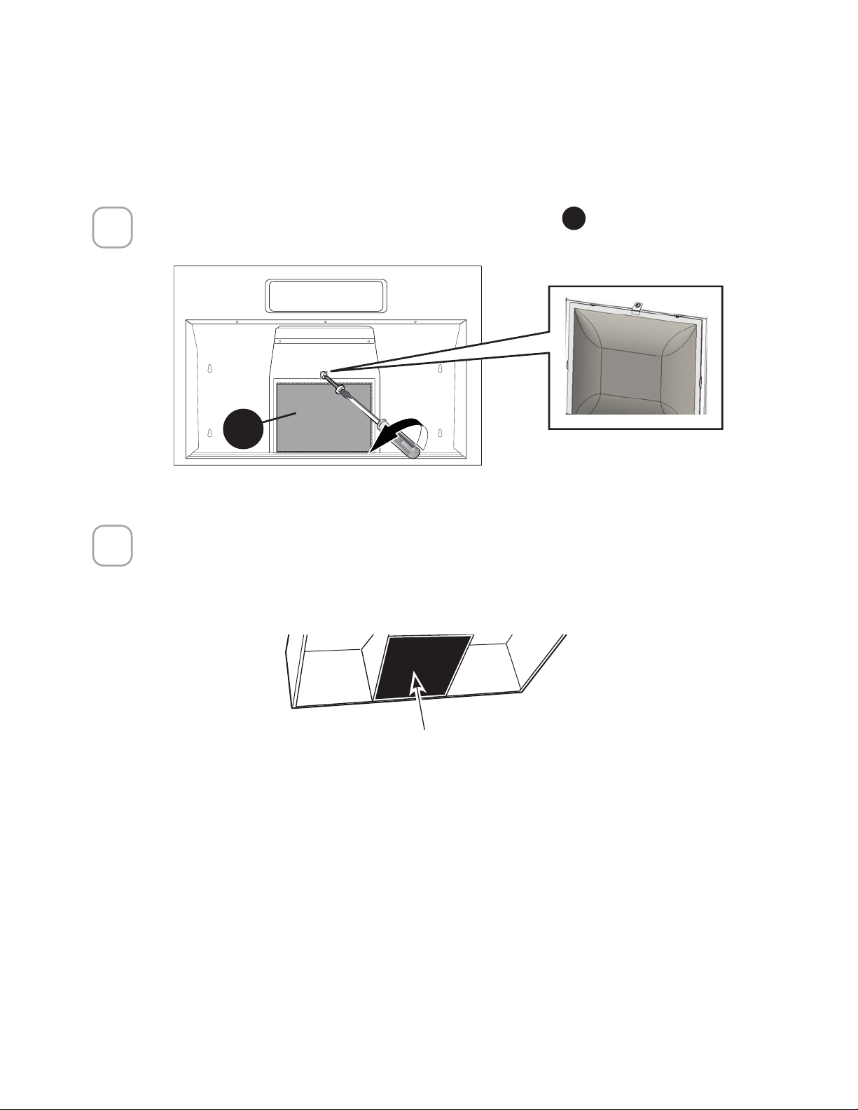
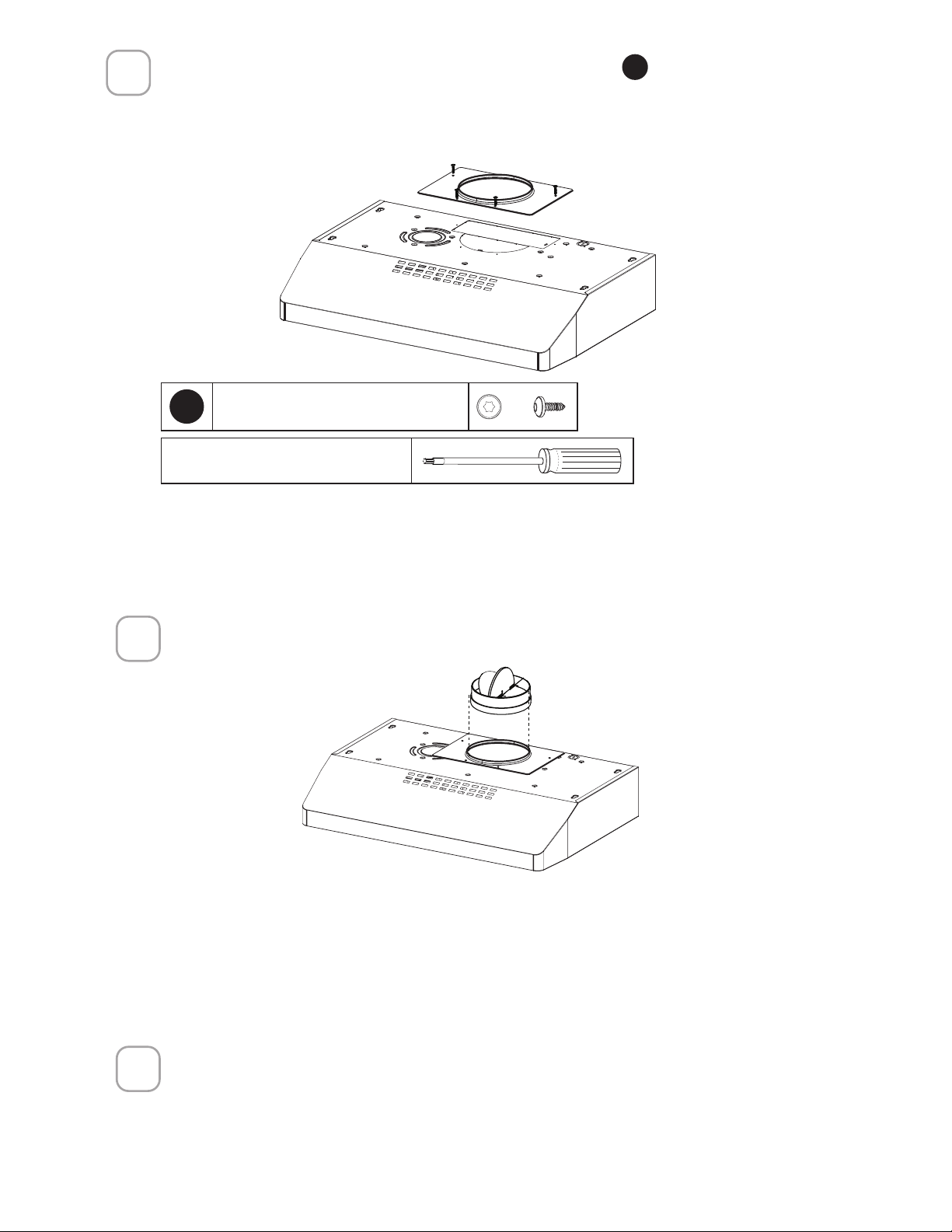
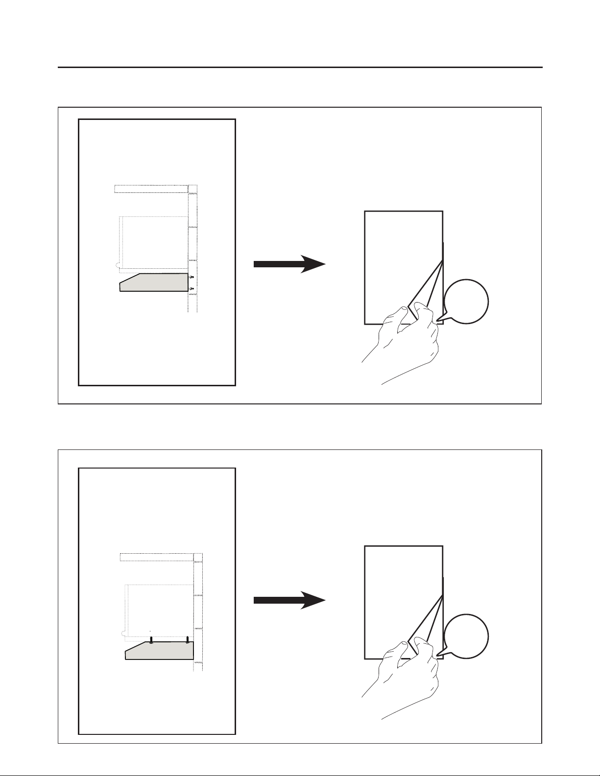
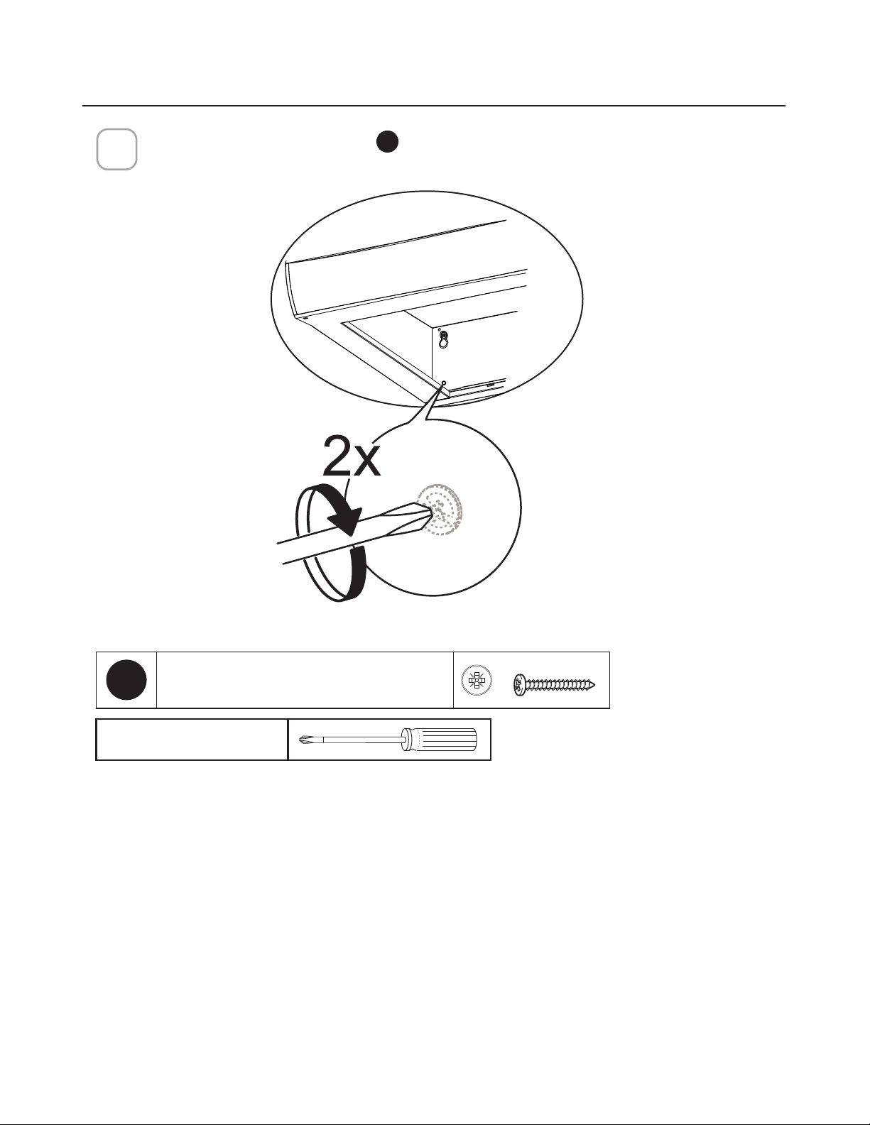
ALL DUCTED VENTING METHOD
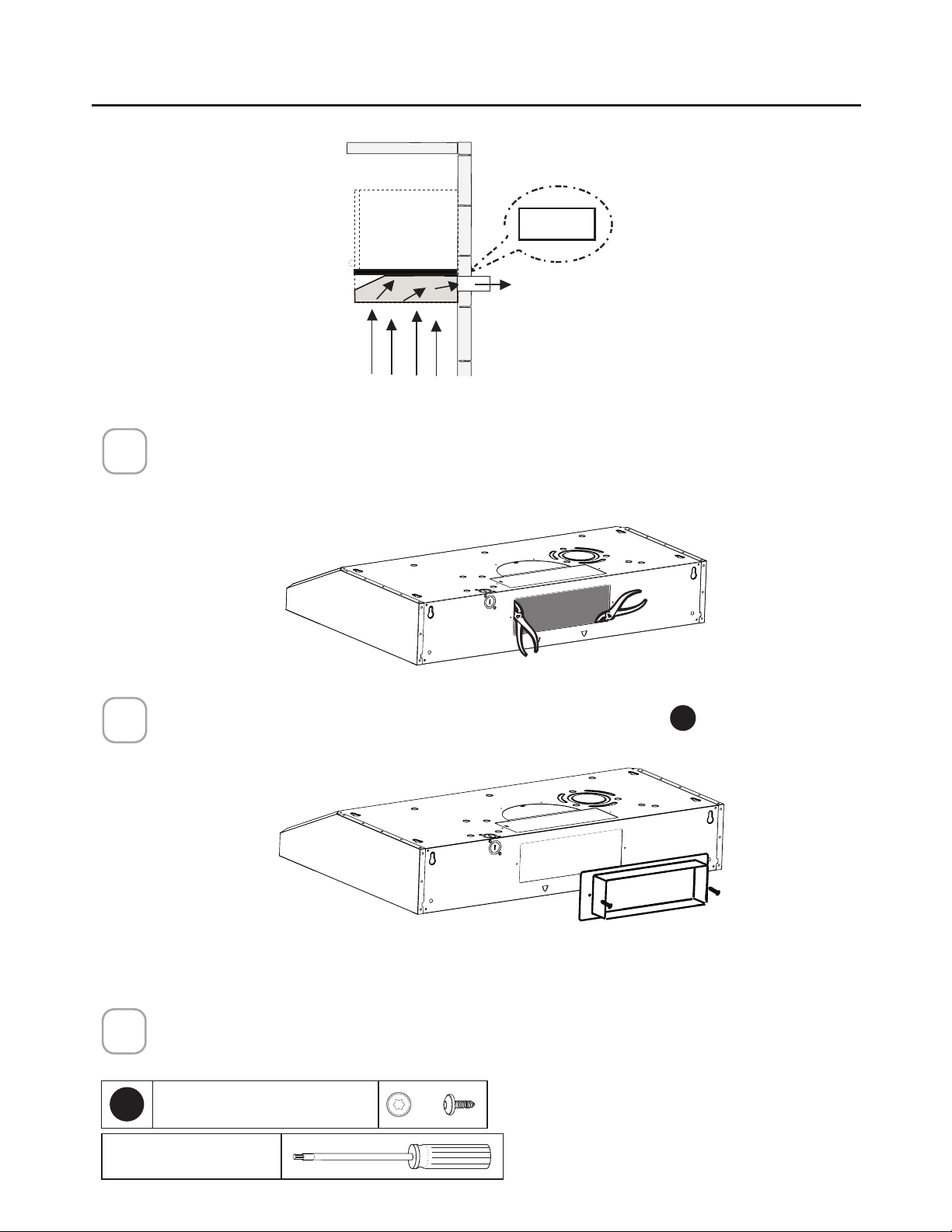
REVERSE THE BAFFLE FOR DUCTED INSTALLATIONS ONLY
Remove the baffle from the top of the hood. Reinstall the baffle so the short side marked
“VENTED” is visible. The long side of the baffle should be inside the hood.
1
³9(17('´LVYLVLEOH
2
,QVWDOOWKHJUHDVH´OWHU
Y
and attach the screw as shown.
Y
"VENTED" is visible
13
DUCTED VENTING METHOD OPTIONS
DUCTED WITH 7" ROUND OUTLET:
– Vertical
– Horizontal
DUCTED WITH 3 1/4" X 10" RECTANGULAR OUTLET
– Vertical
– Horizontal
7"
Rear
Top
10"
3 1/4"
10"
3 1/4"
Rear
Top
Go to page 14
Go to page 16
NON DUCTED - RECIRCULATION OPTION
Requires purchase of
Activated Charcoal
Accessory
Go to page 17
14
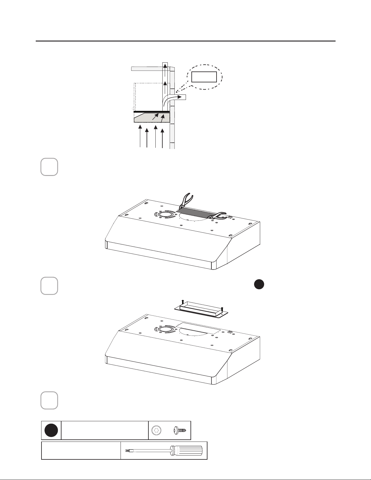
DUCTED - 7" ROUND OUTLET
Cut where indicated.
Remove both the rectangular and semicircle areas with metal shears.
Rear
Top
7"
Required; 7" Round
Damper purchase
separately.
1
Caution: If an elbow
is required, do it
as far away from
the hood's exhaust
opening as possible.
15
Install the Flange with Flange transition screws
F
.
Connect the 7" Round Metal Ductwork to the Roof or Wall Cap purchased separately
and then attach ductwork.
Go to page 19
2
Install 7" Round Damper purchased separately. Secure damper with foil duct tape.
3
NOTE: The Flange must be mounted with the lip facing upward.
2QO\XVHWKHVFUHZVSURYLGHGIRUWKHµDQJH
Torx Screwdriver
F
7RU[6FUHZV[
4
16
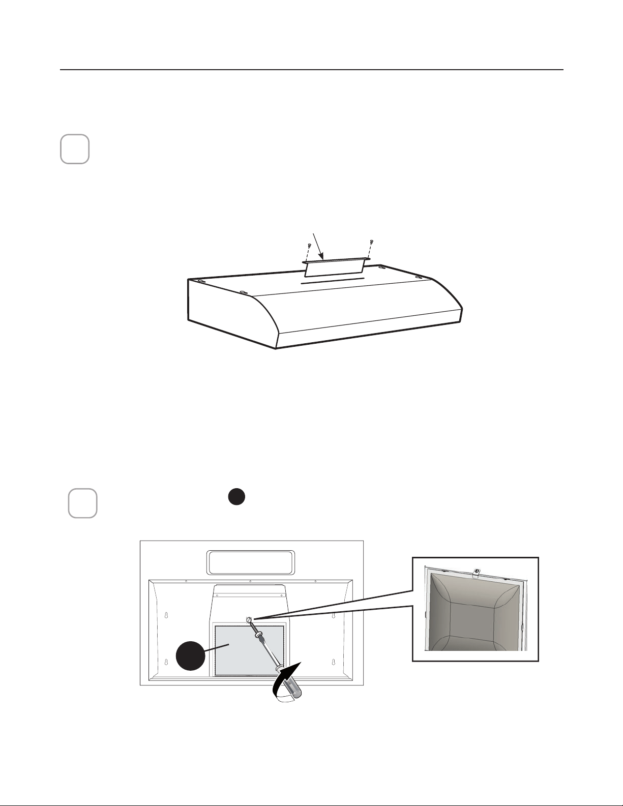
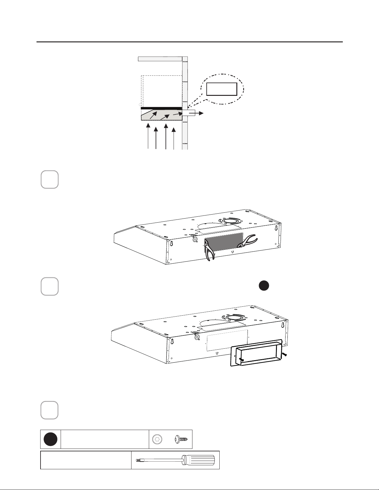
Choose the rectangular upper air outlet or rectangular rear air outlet and cut where
indicated (See page 17 for Rear Outlet).
Install the included rectangular air outlet with two screws
F
.
Connect the metal ductwork to the Roof or Wall Cap purchased separately and
then attach ductwork.
Rear
Top
Top
3
1/4
" x 10"
DUCTED - 3 1/4" X 10" RECTANGULAR OUTLET
ON TOP
1
2
3
Torx Screwdriver
F
7RU[6FUHZV[
Caution: If an elbow is required,
do it as far away from the
hood's exhaust opening as
possible.
17
Go to page 19
Rear
Rear
3
1/4
" x 10"
Use the rear air outlet and cut where indicated.
Install the included rectangular air outlet with two screws
F
.
1
2
Torx Screwdriver
F
7RU[6FUHZV[
DUCTED - 3 1/4" X 10" RECTANGULAR OUTLET
REAR
Caution: If an elbow is required,
do it as far away from the
hood's exhaust opening as
possible.
Connect the metal ductwork to the Roof or Wall Cap purchased separately and
then attach ductwork.
3

18
NON DUCTED RECIRCULATION OPTION
Go to page 19
1
,QVWDOOWKHFKDUFRDO´OWHU
X
and attach the screw as shown.
X

19
CHOOSING THE MOUNTING METHOD
Installation for Mounting on the Wall
Installation for Mounting to the cabinet
Page
20
Page
24
20
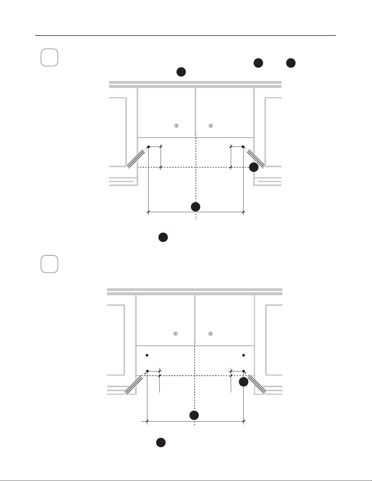
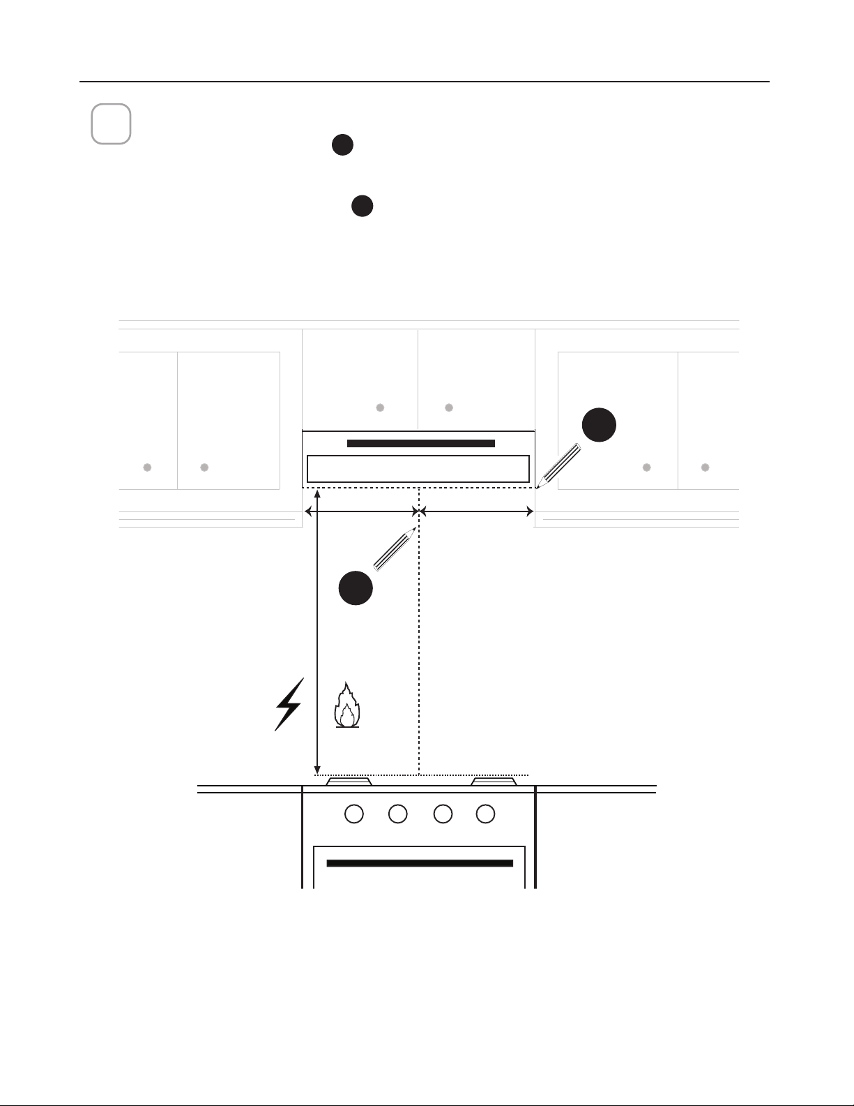
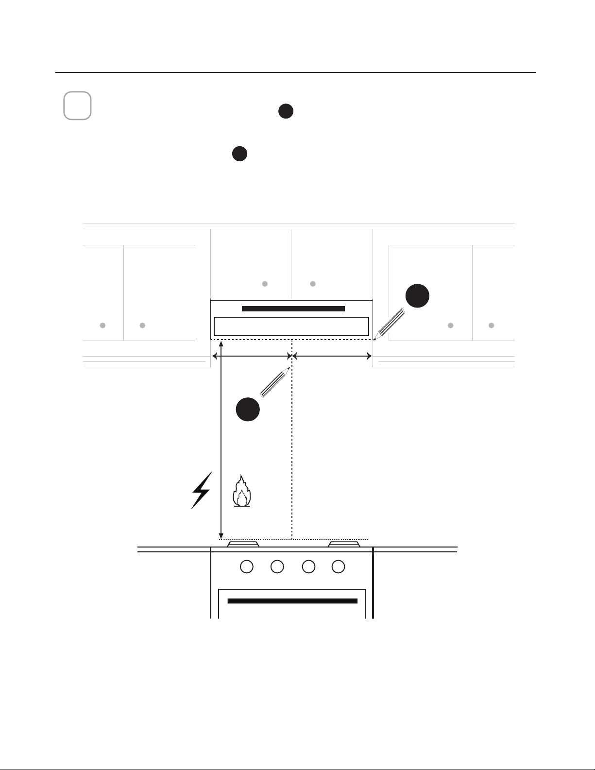
DRAW POSITIONING LINES
Draw a vertical line
H
from the supporting back wall to the ceiling or upper limit, at
the center of the area in which the hood will be installed.
Draw a horizontal line
I
from where the bottom edge of hood will be located, to
a minimum of 24" above an electric cooking surface and 30" above a gas cooking
surface.
1
MIN. 24" OVER ELECTRIC/MIN. 30" OVER GAS
I
H
MOUNTING RANGE HOOD ON WALL
==
Min. 24" Min.30"
21
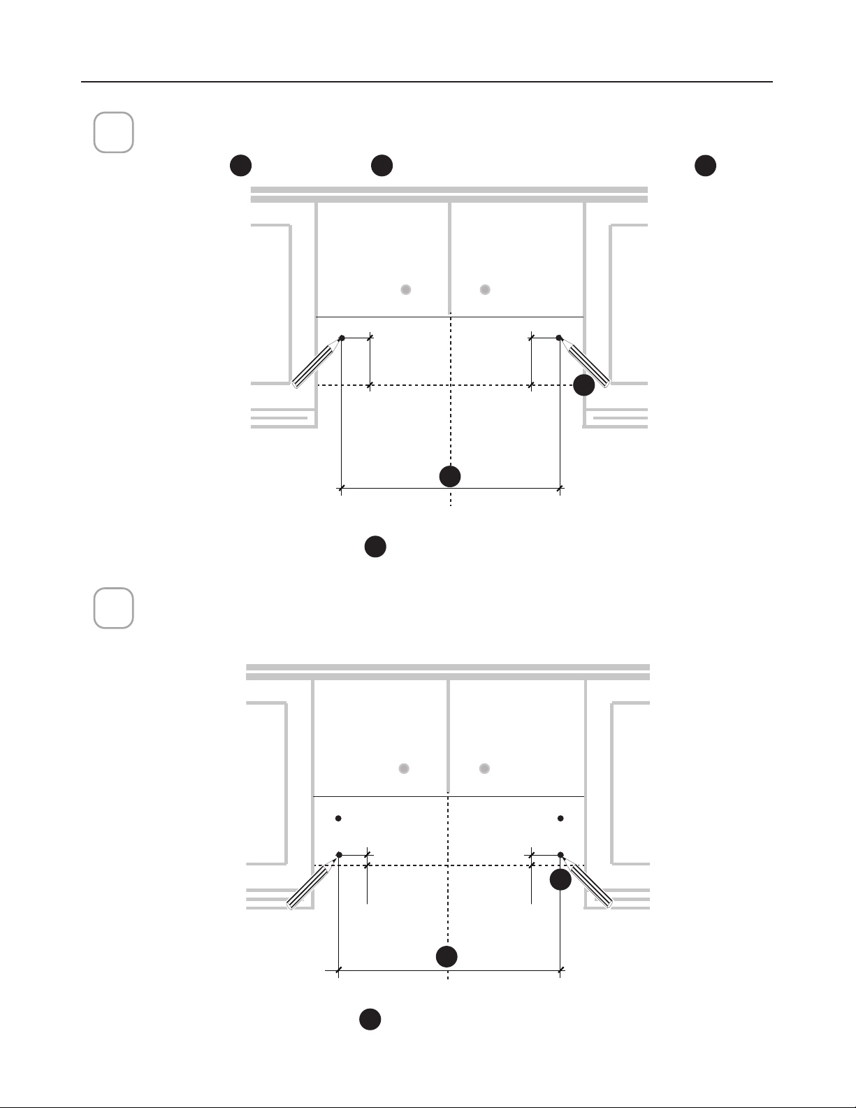
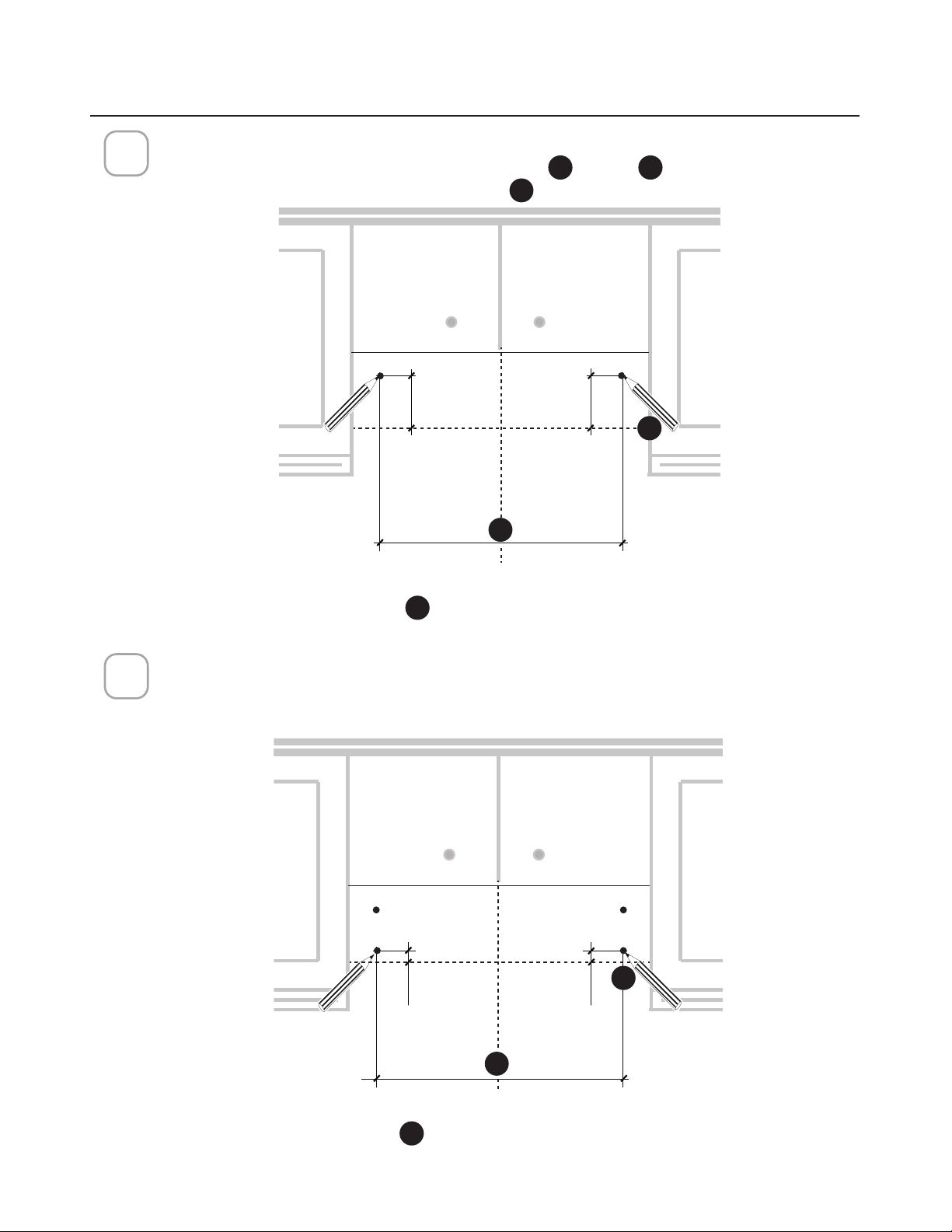
Mark the wall for the upper anchors.
0DUNWKHZDOOZKHUHLQGLFDWHGDERYHWKHKRUL]RQWDO
I
line at
J
distance on
the left and right of the vertical line
H
.
3
1”
1”
24” -->A=213/8”
A
4 15/16”
4 15/16”
A
Mark the wall for lower anchors.
Mark 1” below the Step 2. Upper Anchors. Take care to keep level.
24" = 21
24" = 21
3/8
3/8
"
30" = 27
30" = 27
3/8
3/8
"
24" = 21
24" = 21
3/8
3/8
"
30" = 27
30" = 27
3/8
3/8
"
MOUNTING RANGE HOOD ON WALL
2
I
J
H
I
J
H
22
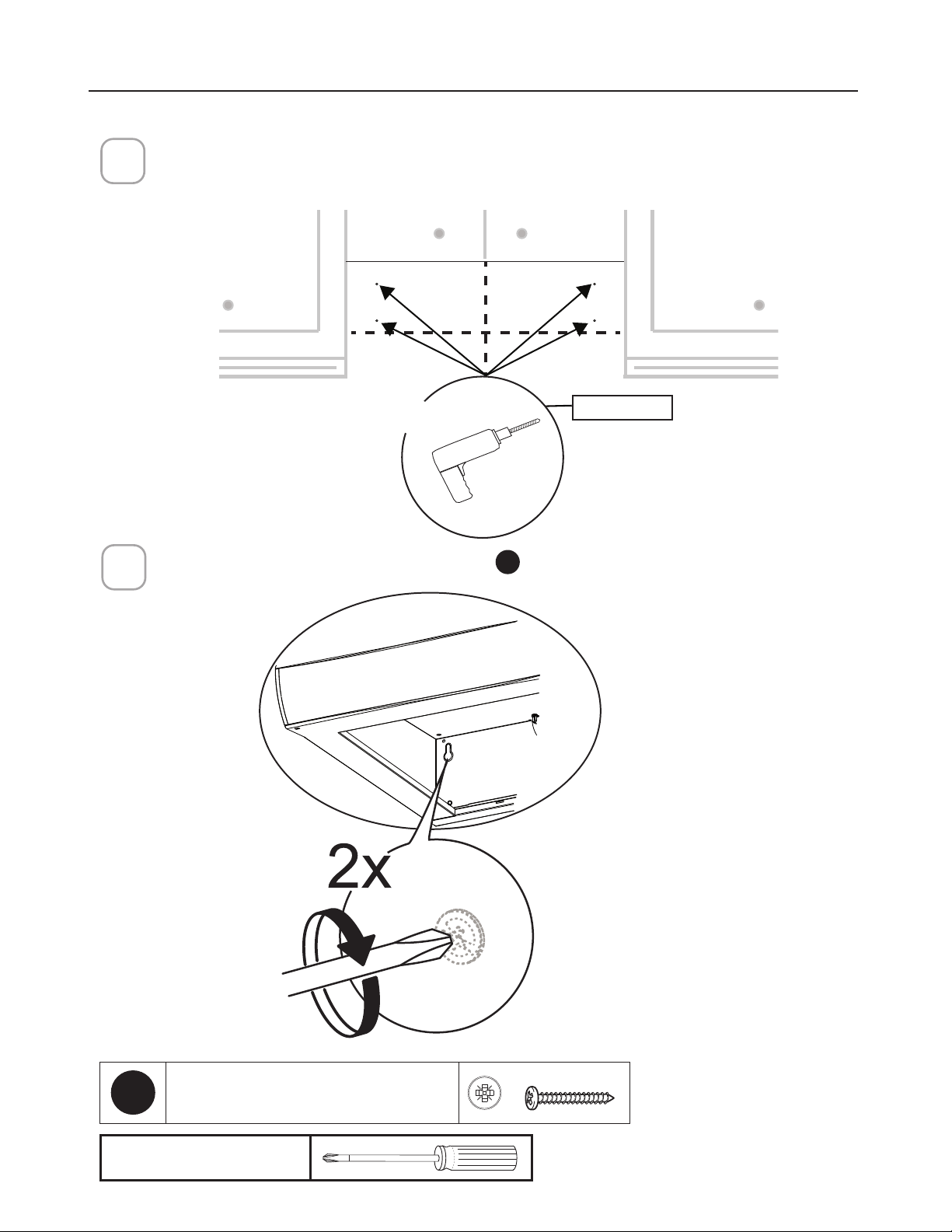
'ULOODWKKROHGLUHFWO\LQWRWKHZDOODWWKHFHQWHUSRLQWVPDUNHGLQVWHS
If fastener locations do not align with the studs, insert the purchased wall plugs in the holes.
In upper holes use two of the supplied screws
E
to secure the hood body to the wall.
´
;
5
Pozi Screwdriver
MOUNTING RANGE HOOD ON WALL
4
E
3R]L6FUHZV[

23
Using two remaining screws
E
anchor the hood in lower holes as indicated.
6
MOUNTING RANGE HOOD ON WALL
Pozi Screwdriver
E
3R]L6FUHZV[
24
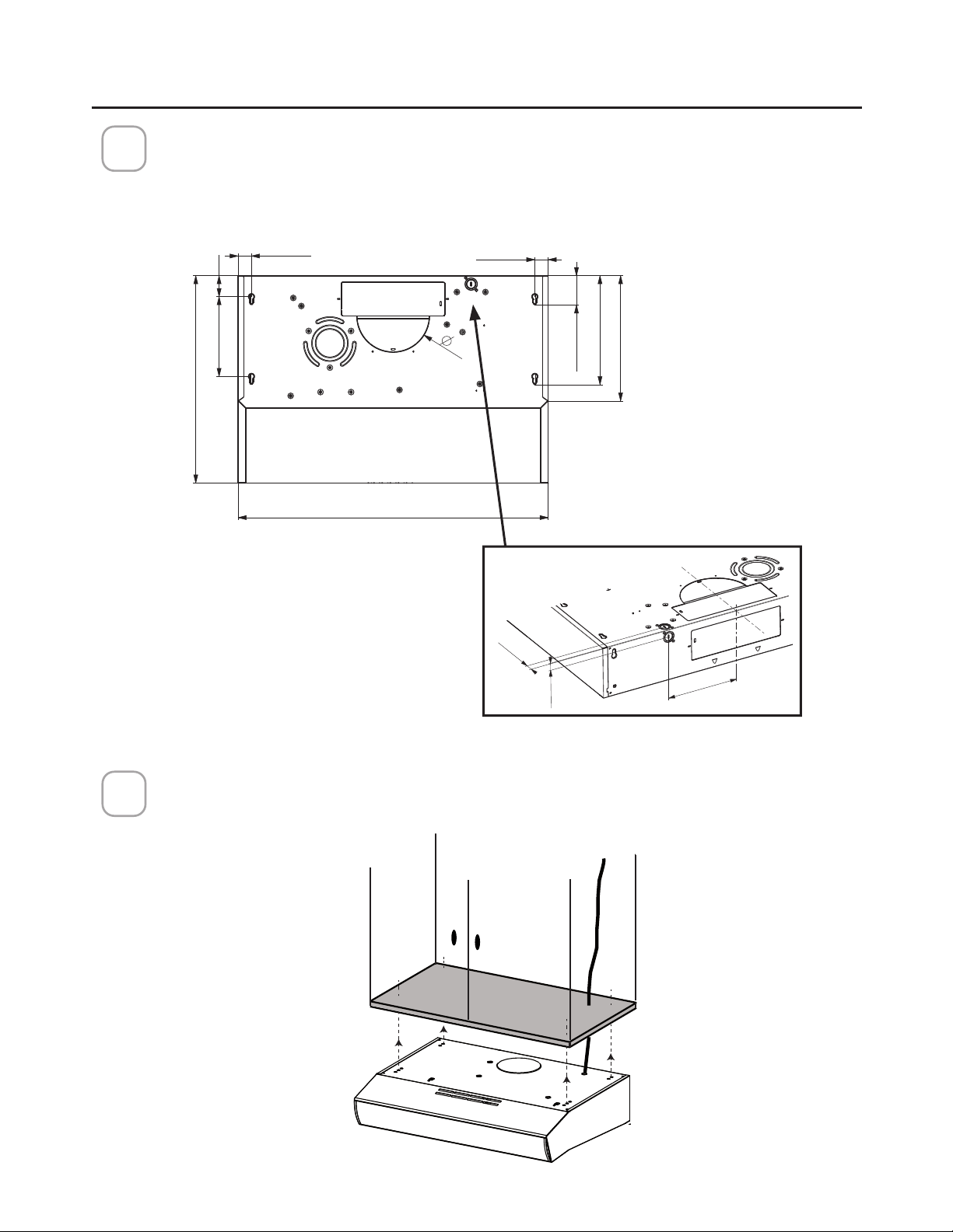
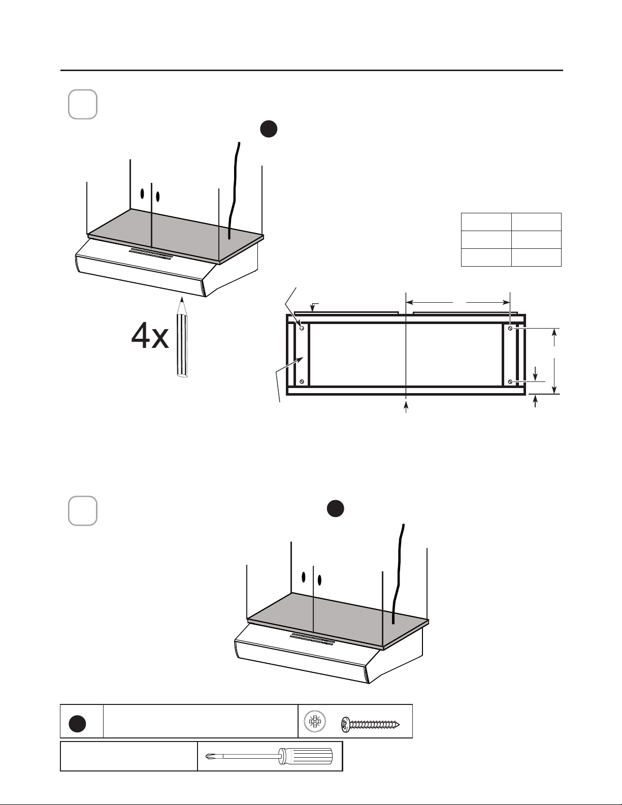
MOUNTING RANGE HOOD UNDER THE CABINET
20"
24"-30"-36"
12"
7"
2" 13/16
10" 1/2
1" 5/16
1" 5/16
7" 11/16 2"
7" 1/2
13/16"
13/16"
Locate the hole on the Range Hood for the power cord (See Section " CHOOSE
VERTICAL OR HORIZONTAL ELECTRICAL CONNECTION KNOCKOUT'S ") and pass
the cord through the appropriate hole.
Lift the hood to the cabinet and pass the power cord through the appropriate holes
on the Range Hood and through the cabinet to the power source.
1
2
Top View
BackView
25
Mark the holes for attaching the hood to the cabinet. Verify the measurement with the
diagram on the previous page.
NOTE: Drive the 4
E
screws partway into the bottom of the cabinet (or wood shims).
3
Attach the Hood body with 4 screws
E
from the bottom available with the hood.
4
E
3R]L6FUHZV[
Pozi Screwdriver
MOUNTING RANGE HOOD UNDER THE CABINET
Cabinet X
24" "
30" "
:RRGVKLPV
UHFHVVHGERWWRP
FDELQHWVRQO\
&HQWHU
OLQH
&DELQHW%RWWRP
&DELQHWIURQW
»´
»´
;
+RRG
PRXQWLQJ
VFUHZV
Center
line
Wood shims
(recessed-bottom
cabinets only)
Hood mounting screws (4)
Cabinet front
Cabinet bottom
26
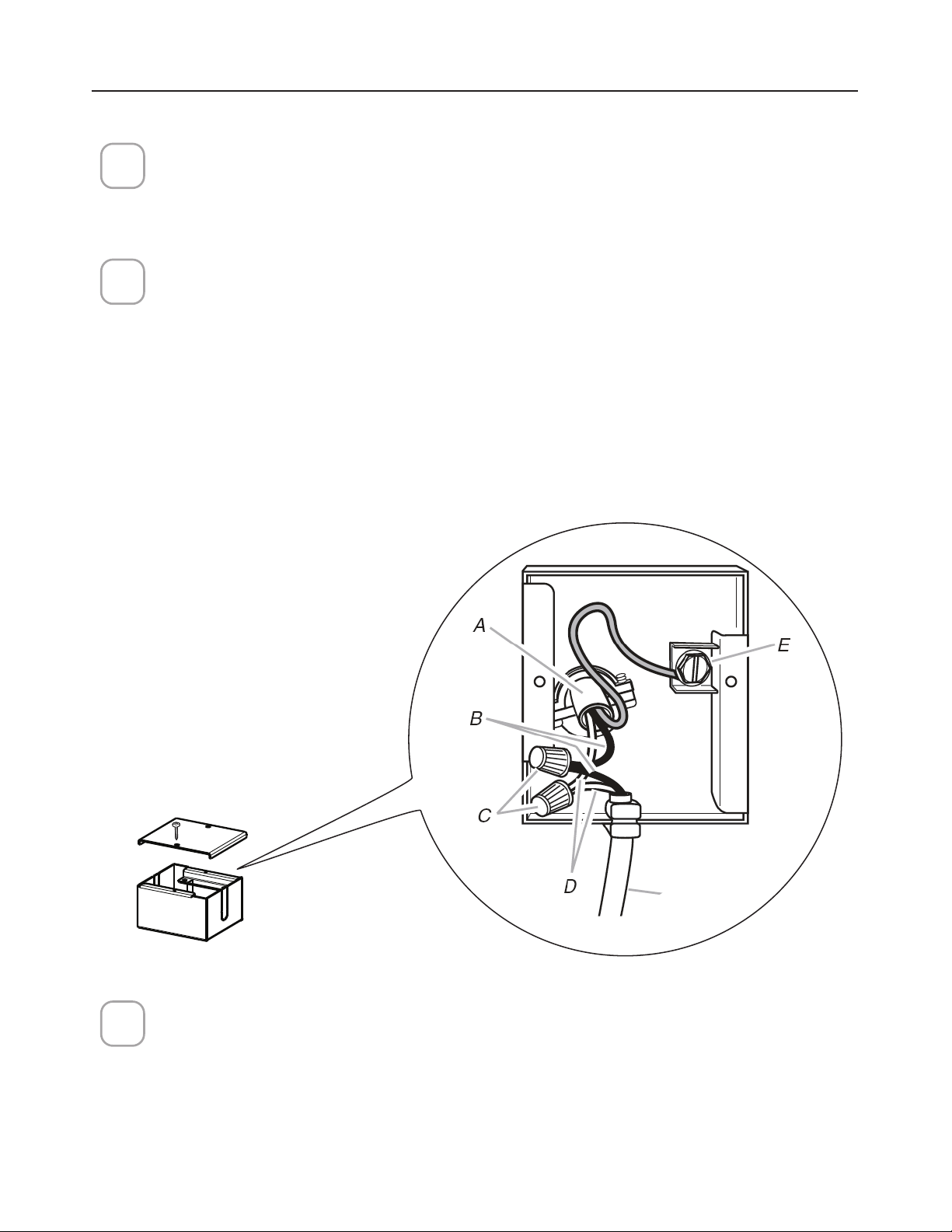
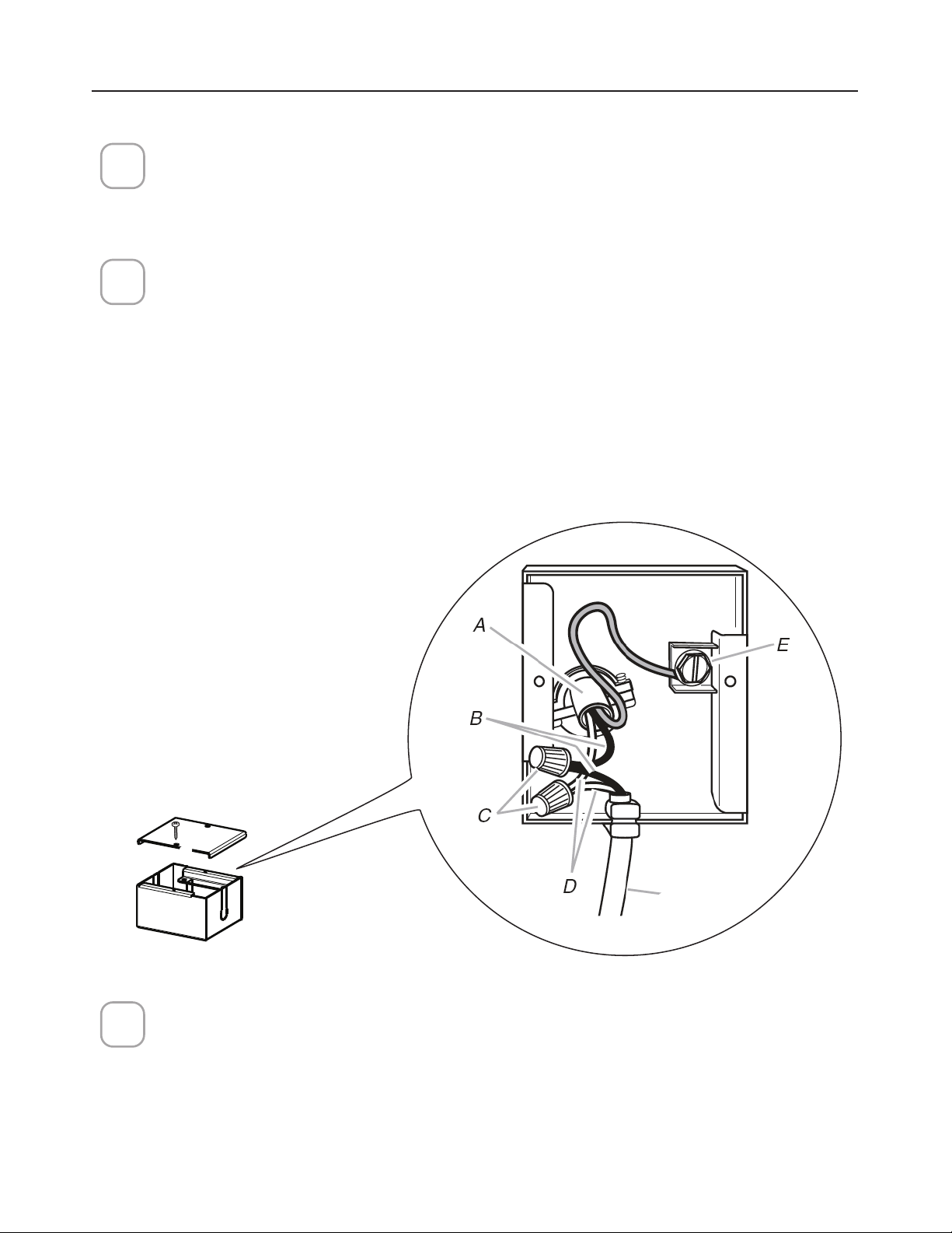
CONNECTING ELECTRICITY
Connecting the House Power.
Caution! Do not turn on the house power until the installation is complete.
• Feed the Power Supply Cable through the electrical knock out.
Wiring Box Connections.
• Attach the White lead of the Power Supply (A) to the White lead of the Range
Hood (D) with a twist-on type connector.
• Attach the Black lead of the Power Supply to the Black lead of the Range Hood
(B) with a twist-on type wire connector (C).
• Connect the Green (E) (Green and Yellow) ground wire under the grounding
screw.
1
3
2
Hood
wiring
5HSODFHWKH´HOGZLULQJFRPSDUWPHQWFRYHUDQGWKHJUHDVH´OWHUV
27
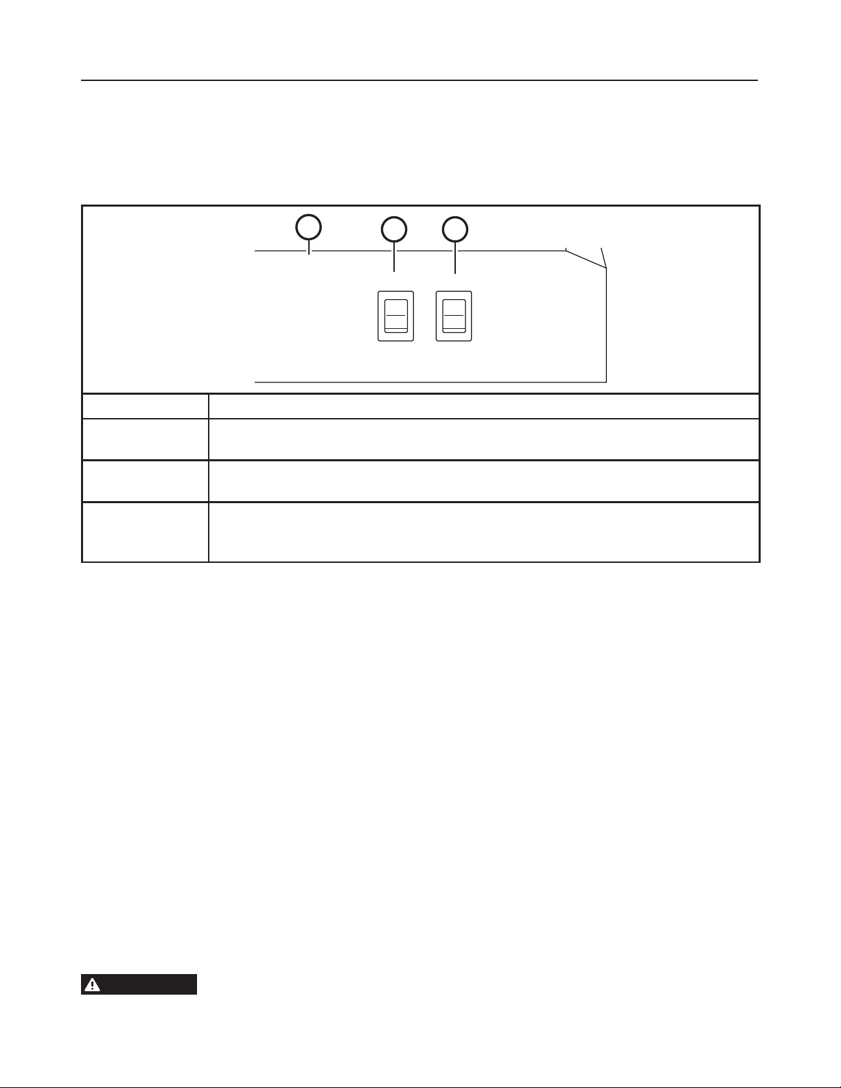
OPERATING THE CONTROLS
FOR BEST RESULTS
6WDUWWKH5DQJH+RRGVHYHUDOPLQXWHVEHIRUHFRRNLQJWRGHYHORSSURSHUDLUµRZ$OORZWKH
Range Hood to operate for several minutes after cooking is complete to clear all smoke and
odors from the kitchen.
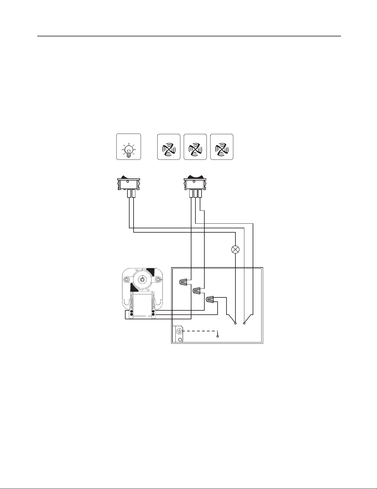
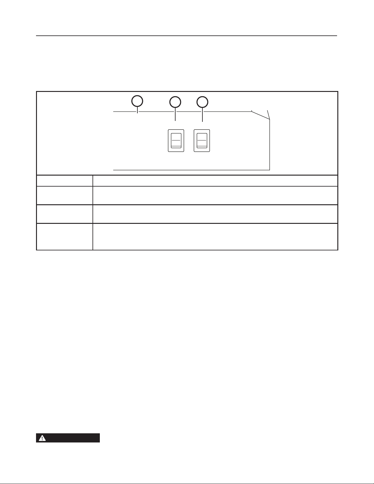
Light Fan
On
Off
Hi
Lo
Off
1
23
Button Function
1
Rangehood Control Panel:
The control panel is located on the front of the canopy.
2
Light Switch:
Light switch toggles between On and Off.
3
Fan Power Switch:
The power switch toggles between fan settings Hi, Lo, and Off.
3DLQWHG6XUIDFHVRQVRPHPRGHOV
Do not use a steel wool pads or other abrasive cleaners; they will scratch the surface.
Clean grease-laden surfaces of the hood frequently. To clean the hood surface, use a hot, damp
cloth with a mild detergent suitable for painted surfaces. About one tablespoon of ammonia
may be added to the water. Use a clean, hot, damp cloth to remove soap. Dry with a dry, clean
cloth.
NOTE: :KHQFOHDQLQJWDNHFDUHQRWWRFRPHLQFRQWDFWZLWK´OWHUVDQGRWKHUVXUIDFHV
CAUTION
When cleaning the hood surfaces, be certain that you do not touch the light
with moist hands or cloth. A warm or hot light may break if touched with a moist surface.
Always let the light cool completely before cleaning around it.
28
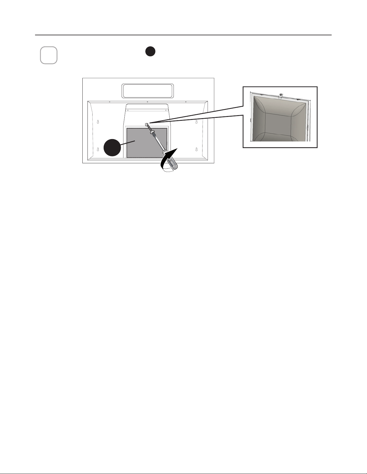
CARING FOR FILTERS
5HPRYHWKHVFUHZDVVKRZQDQGWDNHRXWWKHJUHDVH´OWHU
Y
.
:DVKWKH´OWHUZLWKRXWEHQGLQJLW/HDYHLWWRGU\WKRURXJKO\EHIRUHUHSODFLQJ,IWKH
VXUIDFHRIWKH´OWHUFKDQJHVFRORURYHUWLPHHI´FLHQF\ZLOOQRWEHDIIHFWHG
)LWWKHWDEVDWWKHERWWRPRIWKH´OWHULQWRWKHVORWVLQWKHEDFNRIWKH´OWHURSHQLQJ
/LIWXSWKHIURQWVLGHRIWKH´OWHUDQGSXVKJHQWO\XQWLOWKH´OWHUORFNVLQWRSODFH
$WWDFKWKH´OWHUDQGORFNLWZLWKWKHVFUHZSUHYLRXVO\UHPRYHG
1
2
3
CLEANING METAL GREASE FILTERS
7KHPHWDOJUHDVH´OWHUVFDQEHFOHDQHGLQKRWGHWHUJHQWVROXWLRQRUZDVKHGLQWKHGLVKZDVKHU
They should be cleaned every 2 months use, or more frequently if use is particularly heavy.
NOTES:
&OHDQLQJLQDGLVKZDVKHUPD\GXOOWKH´QLVKRIWKHPHWDOJUHDVH´OWHUV
(QVXUHWKDWWKH´OWHUVDUHFRPSOHWHO\GU\EHIRUHLQVWDOOLQJWKHPEDFNLQWRWKH5DQJH+RRG
CLEANING EXTERIOR SURFACES
3OHDVHQRWHDEUDVLYHVDQGVFRXULQJDJHQWVFDQVFUDWFKUDQJHKRRG´QLVKHVDQGVKRXOGQRWEH
XVHGWRFOHDQ´QLVKHGVXUIDFHV
6WDLQOHVV6WHHO´QLVKFOHDQLQJLQVWUXFWLRQV
Clean exterior surfaces with a commercially available stainless steel cleaner.
Y

29
5HPRYHWKHVFUHZDVVKRZQDQGWDNHRXWWKHFKDUFRDO´OWHU
X
.
1
REPLACING ACTIVATED CHARCOAL FILTER
The Activated Charcoal Filters are not washable and cannot be regenerated, and must be
replaced approximately every 4 months of operation, or more frequently with heavy usage.
Contact Faber for more information on the replacement charcoal. DO NOT rinse, or put charcoal
´OWHUVLQDQDXWRPDWLFGLVKZDVKHU
5HSODFHDEOHFKDUFRDOILOWHU
X
Pull down on the center of the front edge of the filter. The filter will then slip out of
the retaining tabs on the back. To replace, Slip the back edge of the filter into the
retaining tabs and push the front edge up until it snaps into place.
$WWDFKWKH´OWHUDQGORFNLWZLWKWKHVFUHZSUHYLRXVO\UHPRYHG
2
5HSODFHDEOHFKDUFRDO´OWHU
30
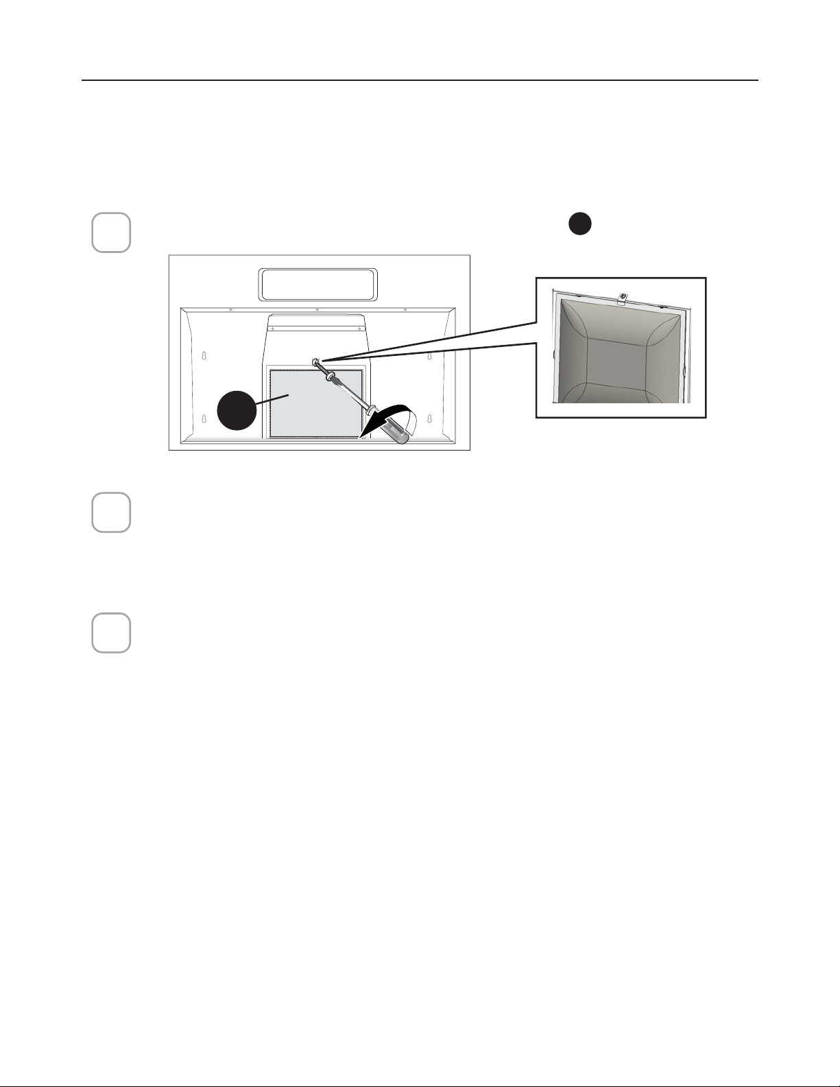
REPLACING LIGHTING
1
2
Suggested replacement with a type A15 incandescent bulb, E26, 40 watts
3
Before attempting to replace the
lights, make sure that the light
switch is turned off.
Remove the light cover by pressing
WKHVLGHVZLWKWZR´QJHUVXQWLOWKH
side prongs are released. Lift the
light cover and slide it toward you in
one motion.
Unscrew light counterclockwise to
unlock light and pull out. Replace
with new light of same type
(standard incandescent), making
sure socket is properly inserted into
the housing of the lamp holder.
Attention: The bulbs could be hot,
please wait some minutes before
the replacing.
To replace the light cover, insert
the prong located at the end of
the cover into the top opening.
Gently push the cover up and
SUHVVWKHVLGHVWR´WWKHVLGH
prongs into the side openings.
Release and the cover will lock
into position.
/LJKWFRYHU
4
CAUTION –
RISK OF FIRE,
MAX 60 W
TYPE A19 LAMP
!
Light cover
31
WIRING DIAGRAM
E
%/.
D
9/7
02725&';
:,5,1*
%2;
%/.
:+7
5('
E
5('
2))
%/.
D
%/.
*1'
:+7
+22',17(51$/&21752/
/$03
:+7
1
/,1(
9DF+]
%/.
/
%/.
32
WARRANTY
January 4, 2016
FABER CONSUMER WARRANTY & SERVICE
All Faber products are warranted against any defect in materials or workmanship for the original purchaser
for a period of 1 year from the date of original purchase (requires proof of purchase). This warranty covers
labor and replacement parts. Faber, at its option, may repair or replace the product or components
necessary to restore the product to good working condition. To obtain warranty service, contact the dealer
from whom you purchased the range hood, or the local Faber distributor. If you cannot identify a local Faber
distributor, contact us at (508) 358-5353 for the name of a distributor in your area.
The following is not covered by Faber's warranty:
1. Service calls to correct the installation of your range hood, to instruct you how to use your range hood, to
replace or repair house fuses or to correct house wiring or plumbing.
2. Service calls to repair or replace range hood light bulbs, fuses or filters. Those consumable parts are
excluded from warranty coverage.
3. Repairs when your range hood is used for other than normal, single-family household use.
4. Damage resulting from accident, alteration, misuse, abuse, fire, flood, acts of God, improper installation,
installation not in accordance with electrical or plumbing codes or Faber documentation, or use of products
not approved by Faber.
5. Replacement parts or repair labor costs for units operated outside the United States or Canada, including
any non-UL or C-UL approved Faber range hoods.
6. Repairs to the hood resulting from unauthorized modifications made to the range hood.
7. Expenses for travel and transportation for product service in remote locations and pickup and delivery
charges. Faber range hoods should be serviced in the home.
THIS WARRANTY DOES NOT ALLOW RECOVERY OF INCIDENTAL OR CONSEQUENTIAL DAMAGES, INCLUDING, WITHOUT
LIMITATION, DIRECT, INDIRECT, INCIDENTAL, SPECIAL OR CONSEQUENTIAL DAMAGES, PERSONAL INJURY/WRONGFUL
DEATH OR LOST PROFITS FABER WARRANTY IS LIMITED TO THE ABOVE CONDITIONS AND TO THE WARRANTY PERIOD
SPECIFIED HEREIN AND IS EXCLUSIVE. EXCEPT AS EXPRESSLY SPECIFIED IN THIS AGREEMENT, FABER DISCLAIMS ALL
EXPRESS OR IMPLIED CONDITIONS, REPRESENTATIONS, AND WARRANTIES INCLUDING, WITHOUT LIMITATION, ANY
IMPLIED WARRANTIES OF MERCHANTABILITY OR FITNESS FOR A PARTICULAR PURPOSE
.
This warranty gives you specific legal rights that may vary from state to state.
Model#: ______________________________ Serial #: _____________________________

33
TABLE DES MATIÈRES
Section Page
Importantes consignes de sécurité 34
Dimensions de la hotte 38
Hauteur requise pour l’installation 39
Pièces 40
Outils requis 41
Choisir l'entrée électrique défonçable verticale ou horizontale
Choisir l'entrée électrique défonçable verticale ou horizontale 42
Options avec ventilation canalisée 45
Canalisation - conduit circulaire 7" 46
Canalisation - conduit rectangulaire 3 1/4" x 10" du dessus
48
Canalisation - conduit rectangulaire 3 1/4" x 10" à l’arrière
49
Choisir la méthode de montage
51
Montage de la hotte au mur
52
Montage de la hotte sous l’armoire
56
Branchement électrique
58
Utilisation des commandes
59
(QWUHWLHQGHV´OWUHV
60
Remplacement de l’éclairage
62
Schéma de câblage
63
Garantie
64

34
IMPORTANTES CONSIGNES DE SÉCURITÉ
VEUILLEZ LIRE ET CONSERVER LA PRÉSENTE NOTICE AVANT DE
COMMENCER L'INSTALLATION DE LA HOTTE DE CUISINE
AVERTISSEMENT: - POUR RÉDUIRE LE RISQUE D'UN FEU DE GRAISSE SUR LA TABLE
DE CUISSON:
a) Ne laissez jamais sans surveillance les éléments de la surface de cuisson à température
élevée. Les bouillonnements excessifs peuvent provoquer de la fumée et les débordements
GHJUDLVVHSHXYHQWVHQµDPPHU/KXLOHGRLWrWUHFKDXIIpHOHQWHPHQWjXQHWHPSpUDWXUH
basse ou moyenne.
b) Assurez-vous de toujours mettre en marche la hotte lorsque vous cuisinez à température
pOHYpHRXSUpSDUH]XQPHWVµDPEpSH[FUrSHV6X]HWWHFHULVHVMXELOpE§XIµDPEp
c) Nettoyez régulièrement les ventilateurs d'aspiration. Assurez-vous de ne pas laisser de
ODJUDLVVHVDFFXPXOHUVXUOHYHQWLODWHXURXOH´OWUH
G8WLOLVH]WRXMRXUVGHVSRrOHVHWFDVVHUROHVGHODWDLOOHDSSURSULpH8WLOLVH]WRXMRXUVGHV
ustensiles de cuisine de la taille adaptée à celle de l'élément chauffant.
AVERTISSEMENT: - POUR PRÉVENIR LES BLESSURES EN CAS DE FEU DE GRAISSE SUR
LA TABLE DE CUISSON, SUIVEZ LES RECOMMANDATIONS SUIVANTES*:
a) ÉTOUFFEZ LES FLAMMES à l'aide d'un couvercle hermétique, d'une plaque à biscuits ou
d'un plateau métallique, puis éteignez le brûleur. FAITES ATTENTION AUX BRÛLURES.
Si le feu ne s'éteint pas immédiatement, QUITTEZ LES LIEUX ET APPELEZ LES POMPIERS.
b) NE PRENEZ JAMAIS UNE CASSEROLE EN FLAMME - Vous pourriez vous brûler.
c) N'UTILISEZ JAMAIS DE L'EAU, ni un linge à vaisselle ou un torchon mouillé, pour éteindre
le feu. Cela pourrait provoquer une violente explosion de vapeur.
d) Utilisez un extincteur UNIQUEMENT si:
9RXVrWHVFHUWDLQTXLOVDJLWGXQH[WLQFWHXUGHFODVVH$%&HWTXHYRXVFRQQDLVVH]
bien son mode d'emploi.
2. Le feu est de faible intensité et se limite à l'endroit où il a démarré.
3. Les pompiers ont déjà été appelés.
8QHYRLHGHVRUWLHVHWURXYHGHUULqUHYRXVSHQGDQWTXHYRXVpWHLJQH]OHVµDPPHV
*
D'après le guide «Kitchen Firesafety Tips» publié par la NFPA aux États-Unis
AVERTISSEMENT - POUR RÉDUIRE LE RISQUE D'INCENDIE OU DE CHOC ÉLECTRIQUE,
n'utilisez jamais ce ventilateur en association avec un dispositif de réglage de vitesse à
semi-conducteurs.
AVERTISSEMENT - POUR RÉDUIRE LES RISQUES D'INCENDIE, DE CHOC ÉLECTRIQUE OU
DE BLESSURE CORPORELLE, RESPECTEZ LES INSTRUCTIONS SUIVANTES:
1. Utilisez cet appareil uniquement de la façon prévue par le fabricant. Pour toute question,
communiquez avec le fabricant.
2. Avant de procéder à l'entretien ou au nettoyage de l'appareil, coupez l'alimentation au
niveau du panneau électrique et verrouillez-le pour vous assurer que l'électricité n'est pas
rétablie accidentellement. S'il n'est pas possible de verrouiller le dispositif d'interruption
GHODOLPHQWDWLRQDI´FKH]GHIDoRQIHUPHHWELHQYLVLEOHXQDYLVGHGDQJHUSDUH[HPSOH
à l'aide d'une étiquette sur le panneau.
$77(17,21¢'HVWLQpjXQXVDJHGHYHQWLODWLRQJpQpUDOHXQLTXHPHQW1XWLOLVH]SDVFH
dispositif pour l'aspiration de vapeurs ou de matériaux dangereux ou explosifs.
AVERTISSEMENT - POUR RÉDUIRE LES RISQUES D'INCENDIE, DE CHOC ÉLECTRIQUE OU
'(%/(6685(&25325(//(5(63(&7(=/(6,16758&7,21668,9$17(6¢
1. /LQVWDOODWLRQHWOHEUDQFKHPHQWpOHFWULTXHGRLYHQWrWUHUpDOLVpVSDUXQWHFKQLFLHQTXDOL´p

35
TOUTE OUVERTURE DANS LE MUR OU LE PLANCHER À PROXIMITÉ DE LA HOTTE
DOIT ÊTRE SCELLÉE.
Un espace libre d'au moins 24" est requis entre le bas de la hotte et la surface de cuisson ou
le comptoir. Cette hotte a été homologuée par l'UL à cette distance de la surface de cuisson.
L’espace libre minimal requis peut-être plus grand, selon la réglementation en matière de
construction de votre région. Pour les cuisinières à gaz et les cuisinières combinées, un espace
minimal de 30" est recommandé et pourrait être exigé.
Les armoires suspendues de chaque côté de l'appareil doivent se trouver à au moins 18" de la
surface de cuisson ou du comptoir. Consultez la notice d'installation de la surface de cuisson
ou de la cuisinière fournie par le fabricant avant de pratiquer des ouvertures.
INSTALLATION DANS UNE MAISON MOBILE L'installation de cette hotte doit être conforme
à la Partie 3280 de la norme Manufactured Home Construction and Safety Standards, Title 24
CFR (précédemment la partie 280 de la norme Federal Standard for Mobile Home Construction
DQG6DIHW\7LWOH+8'&RQVXOWH]OD´FKHWHFKQLTXHpOHFWULTXH
CRITÈRES DE VENTILATION
Déterminez quelle méthode de ventilation est mieux adaptée à votre application. Les conduits
peuvent passer par le mur ou le toit.
3RXUJDUDQWLUXQHPHLOOHXUHHI´FDFLWpODORQJXHXUGHVFRQGXLWVHWOHQRPEUHGHFRXGHVGRLYHQW
être le plus limités que possible. Le diamètre des conduits devrait être uniforme. N'installez pas
GHX[FRXGHVHQVHPEOH8WLOLVH]XQUXEDQSRXUFDQDOLVDWLRQVD´QGHVFHOOHUWRXVOHVMRLQWVGX
système de conduits. Utilisez un calfeutrage pour sceller les ouvertures dans le mur extérieur
ou le plancher, autour du clapet.
,OQHVWSDVUHFRPPDQGpGXWLOLVHUGHVFRQGXLWVµH[LEOHV/HVFRQGXLWVµH[LEOHVSURYRTXHQW
XQHFRQWUHSUHVVLRQHWGHODWXUEXOHQFHTXLGLPLQXHQWJUDQGHPHQWOHI´FDFLWpGHODSSDUHLO
$VVXUH]YRXV TXH OHVSDFH OLEUH GDQV OH PXU RX OH SODQFKHU HVW VXI´VDQW SRXU OH FRQGXLW
d'évacuation avant de pratiquer les ouvertures. Ne coupez jamais une poutre ou un chevron,
sauf si c'est absolument nécessaire. S'il s'avère nécessaire de couper une poutre ou un chevron,
la construction d'un renforcement est requise.
AVERTISSEMENT - Pour réduire le risque d'incendie, utilisez uniquement des conduits
métalliques.
ATTENTION - Pour réduire le risque d'incendie et pour évacuer adéquatement l'air, assurez-
vous de raccorder les conduits à l'extérieur – Ne diffusez pas l'air d'évacuation dans des
espaces à l'intérieur des murs ou du plafond, ou encore à l'intérieur d'un grenier, d'une
galerie technique ou d'un garage.
et conformément à tous les codes et normes en vigueur, incluant ceux concernant la
construction à l'épreuve du feu.
2. $´QGHJDUDQWLUXQHFRPEXVWLRQHWXQHpYDFXDWLRQDGpTXDWHVGHVJD]SDUOHVFRQGXLWHV
de la cheminée des appareils à combustion, une bonne aération est nécessaire pour
éviter le refoulement. Respectez les lignes directrices fournies par le fabricant du matériel
chauffant, ainsi que les normes de sécurité comme celles publiées par la National Fire
3URWHFWLRQ$VVRFLDWLRQ1)3$HWOD$PHULFDQ6RFLHW\IRU+HDWLQJ5HIULJHUDWLRQDQG
$LU&RQGLWLRQLQJ(QJLQHHUV$6+5$(DX[eWDWV8QLVDLQVLTXHOHVFRGHVHQYLJXHXU
dans votre région.
3. Lorsque vous faites une ouverture ou percez dans un mur ou le plafond, veillez à ne
SDVHQGRPPDJHUOHV´OVpOHFWULTXHVRXGDXWUHVGLVSRVLWLIVFDFKpV
4. /HVYHQWLODWHXUVFDQDOLVpVGRLYHQWWRXMRXUVrWUHUDFFRUGpVjOH[WpULHXU
36
FICHE TECHNIQUE ÉLECTRIQUE
Une alimentation de courant alternatif de 120 volts à 60 Hz est requise sur un circuit à fusible
distinct de 15 ampères. Il est recommandé d'installer un fusible temporisé ou un disjoncteur.
Le fusible doit être calibré conformément aux codes en vigueur pour les caractéristiques
nominales électriques de l'appareil, indiquées sur la plaque signalétique située à l'intérieur
de l'appareil, à proximité du compartiment des câblages externes.
INSTALLATION ÉLECTRIQUE AVEC BOÎTIER DE CONNEXION
CET APPAREIL DOIT ÊTRE UNIQUEMENT BRANCHÉ À L'AIDE DE FILS DE CUIVRE. Le
FDOLEUHGHV´OVGRLWrWUHFRQIRUPHDX[FULWqUHVGHODGHUQLqUHpGLWLRQGX1DWLRQDO(OHFWULFDO
&RGHGHO$16,1)3$HWGHOHQVHPEOHGHVFRGHVHWUpJOHPHQWDWLRQVHQYLJXHXU/H
FDOLEUHGHV´OVHWOHVFRQQH[LRQVGRLYHQWrWUHDGDSWpVDX[FDUDFWpULVWLTXHVQRPLQDOHVGH
l'appareil. Il est possible de se procurer un exemplaire des normes indiquées ci-dessus en
communiquant avec:
National Fire Protection Association
Batterymarch Park
Quincy, Massachusetts 02269 (États-Unis)
Cet appareil devrait être branché directement au sectionneur à fusible (ou au disjoncteur)
SDUXQFkEOHµH[LEOHGHFXLYUHDYHFEOLQGDJHRXJDLQHQRQPpWDOOLTXH/DLVVH]XQ
peu de jeu dans le câble pour permettre le déplacement de l'appareil si des travaux
GHQWUHWLHQVDYpUDLHQWQpFHVVDLUHV8QUDFFRUGGHFRQGXLWKRPRORJXpSDUO8/GH
doit être installé aux deux extrémités du câble d'alimentation (au niveau de l'appareil
et de la boîte de liaison).
/RUVGHODUpDOLVDWLRQGXEUDQFKHPHQWpOHFWULTXHUpDOLVH]XQWURXGHGDQVOHPXU
S'il s'agit d'un trou dans le bois, il doit être poncé pour le rendre lisse. S'il s'agit d'un
WURXGDQVOHPpWDOXQSDVVH´OVHVWUHTXLV
• Le système de ventilation DOIT déboucher à l'extérieur.
• NE FAITES PAS déboucher les conduits dans un grenier ou un autre endroit
fermé.
• N’UTILISEZ PAS un clapet de sécheuse mural de 4".
,OQHVWSDVUHFRPPDQGpGXWLOLVHUGHVFRQGXLWVµH[LEOHV
• N’ENTRAVEZ PASOHµX[GHODLUGHFRPEXVWLRQHWGHYHQWLODWLRQ
• Le non-respect des exigences en matière de ventilation pourrait entraîner un
incendie.
AVERTISSEMENT
!
Installation dans les climats froids
Le système de ventilation doit prévoir un registre antirefoulement supplémentaire pour réduire le
µX[GDLUIURLGLQYHUVHDLQVLTXXQHEDUULqUHWKHUPLTXHQRQPpWDOOLTXHSRXUUpGXLUHODFRQGXFWLRQGHV
températures extérieures. Le registre doit être installé du côté air froid par rapport à la barrière thermique.
La barrière thermique doit être positionnée le plus près que possible de l'endroit où le système de
ventilation pénètre dans la partie chauffée de la maison.

37
• Une mise à la terre électrique est requise pour cette hotte.
• N'UTILISEZ PAS un tuyau d'eau froide pour la mise à la terre si celui-ci est
branché par des joints en plastique, par des rondelles non métalliques ou
d'autres matériaux.
• N'UTILISEZ PAS une conduite de gaz pour la mise à la terre.
• N'INSTALLEZ PAS un fusible sur le circuit neutre ou le circuit de mise à la
terre. La présence d'un fusible dans le circuit neutre ou de mise à la terre
peut entraîner un choc électrique.
&RQVXOWH]XQpOHFWULFLHQTXDOL´pVLYRXVQrWHVSDVFHUWDLQGHODPLVHjODWHUUH
de la hotte.
/HQRQUHVSHFWGHVH[LJHQFHVGHOD´FKHWHFKQLTXHpOHFWULTXHSRXUUDLW
entraîner un incendie.
AVERTISSEMENT
!

38
DIMENSIONS DE LA HOTTE
7 1/4
3
23 15/16” - 29 15/16” - 35 15/16”

39
Min.24” Min.30”
HAUTEUR REQUISE POUR L’INSTALLATION
MIN. 24" AU-DESSUS D’UNE
SURFACE ÉLECTRIQUE
/ MIN. 30" AU-DESSUS D’UNE
SURFACE AU GAZ

40
PIÈCES
RÉF. PIÈCE
A
%kWLGHODKRWWHLQFOXDQWFRPPDQGHVpFODLUDJH´OWUHVYHQWLODWHXU 1
B
Registre (¢[)1
C
Bride circulaire 7" 1
X
Filtre à charbon 1
Y
Filtre à graisse 1
RÉF. PIÈCE
E
9LVjWrWH3R]LGULY[¢
4
F
9LVjWrWHpWRLOH[
4
PIÈCES INCLUSES
B
C
A
X
Y

41
PIÈCES REQUISES
3,¿&(6VXLWH
PIÈCE
Conduit métallique 7" circulaire
&RQGXLWUHFWDQJXODLUH[
Registre 7"
&RQQHFWHXUVGH´OV
Câble d’alimentation électrique.
Chevilles pour cloison sèche ou autre système de
´[DWLRQPXUDOHQIRQFWLRQGHYRWUHLQVWDOODWLRQ
&ODSHWGHWRLWXUHFODSHWPXUDO'RLWrWUHDFKHWp
séparément)
OUTILS REQUIS
OUTILS
Ruban à mesurer
Crayon
3HUFHXVHpOHFWULTXHDYHFIRUHW
Tournevis cruciforme
Tournevis étoile
Tournevis Pozidriv
42
7" 1/2
13/16"
13/16"
CHOISIR L'ENTRÉE ÉLECTRIQUE DÉFONÇABLE
VERTICALE OU HORIZONTALE
1
+RRG
-XQFWLRQ
%R[
Préparation de la hotte pour les entrées prédécoupées électriques
PRÉPARATION DU
SYSTÈME D’ÉLECTRICITÉ -
RETRAIT DE LA BOÎTE DE
JONCTION DE LA HOTTE
Retirez la boîte de jonction
de l'intérieur de la hotte.
Mettez le couvercle et ses
YLVGH´[DWLRQGHF{Wp
Hotte
Jonction
Boîte

43
2
3
7URXDUULqUHKRUL]RQWDO
Choisissez le trou arrière pour le branchement électrique et percez-le avec un tournevis
ou un autre outil.
Pendant l'installation, faites passer le câble d'alimentation électrique par ce trou.
7URXVXSpULHXUYHUWLFDO
Choisissez le trou supérieur pour le raccordement électrique et percez-le à l'aide d'un
tournevis ou d'un autre outil.
Pendant l'installation, faites passer le câble d'alimentation électrique par ce trou.
44
1
³9(17('´LVYLVLEOH
2
Y
MÉTHODE DE VENTILATION TOUT CONDUIT
INVERSEZ LE DÉFLECTEUR POUR LES INSTALLATIONS AVEC CONDUITS UNIQUEMENT
Retirez le déflecteur du haut de la hotte. Réinstallez le déflecteur de sorte que le côté
court marqué «VENTILÉ » soit visible. Le côté long du déflecteur doit se trouver à
l'intérieur de la hotte.
,QVWDOOH]OH´OWUHjJUDLVVH
Y
HW´[H]ODYLVFRPPHLQGLTXp
/DPHQWLRQ¢9(17,/e¢GRLWrWUHYLVLEOH

45
7"
10"
3 1/4"
10"
3 1/4"
OPTIONS DE LA MÉTHODE D’ÉVACUATION PAR CONDUITS
CONDUIT AVEC SORTIE RONDE DE 7" :
– Vertical
– Horizontal
CONDUIT AVEC SORTIE RECTANGULAIRE DE 3 1/4" X 10" :
– Vertical
– Horizontal
Arrière
Haut
Arrière
Haut
Allez à la page 46
Allez à la page 48
OPTION DE RECIRCULATION SANS CONDUIT
Nécessite l'achat de
l'accessoire charbon
actif.
Allez à la page 49

46
1
CONDUIT - SORTIE RONDE DE 7"
Coupez aux endroits indiqués.
Retirez les zones rectangulaires et semi-circulaires avec des cisailles à métaux.
Arrière
Haut
7"
1pFHVVDLUH¢
veuillez acheter le
clapet rond de 7"
séparément.
Attention¢6LXQ
coude est nécessaire,
réalisez-le aussi
loin que possible
de l'ouverture
d'évacuation de la
hotte.
47
2
Tournevis Torx
F
9LV7RU[[
4
Installez la bride avec les vis de transition de la bride
F
.
Raccordez la gaine métallique ronde de 7" au capuchon de toit ou de paroir acheté
VpSDUpPHQWSXLV´[H]ODJDLQH
Allez à la page 51
3
Installez le clapet rond de 7" acheté séparément. Fixez le clapet avec du ruban adhésif
en toile.
REMARQUE¢/DEULGHGRLWrWUHPRQWpHDYHFODOqYUHWRXUQpHYHUVOHKDXW
Utilisez uniquement les vis fournies pour la bride
48
Choisissez la sortie d'air rectangulaire supérieur ou arrière et coupez à l'endroit
indiqué (consultez la page 49 pour sortie à l’arrière).
Installez la sortie d'air rectangulaire fournie à l'aide de deux vis
F
.
Raccordez le conduit métallique au clapet de toiture ou au clapet mural acheté
séparément, puis raccordez les conduits.
Arrière
Haut
Haut
¢1/4" x 10"
CANALISATION - CONDUIT RECTANGULAIRE
¢;'8'(6686
1
2
3
Tournevis étoile
F
9LVjWrWHpWRLOH[
Attention: Si vous devez
installer un coude, placez-le le
plus loin possible de l’ouverture
d’évacuation de la hotte.
49
Passez
à la page 51
Arrière
Arrière
3¢
1/4
" x 10"
Utilisez la sortie d’air arrière et coupez aux endroits indiqués.
Installez la sortie d'air rectangulaire fournie à l'aide de deux vis
F
.
1
2
Tournevis étoile
F
9LVjWrWHpWRLOH[
CANALISATION - CONDUIT RECTANGULAIRE
¢;£/$55,¿5(
Attention¢6LYRXVGHYH]
installer un coude, placez-le le
plus loin possible de l’ouverture
d’évacuation de la hotte.
Raccordez le conduit métallique au clapet de toiture ou au clapet mural acheté
séparément, puis raccordez les conduits.
3
50
1
X
OPTION DE RECIRCULATION SANS CONDUIT
,QVWDOOH]OH´OWUHjFKDUERQ
X
HW´[H]ODYLVFRPPHLQGLTXp

51
CHOISIR LA MÉTHODE DE MONTAGE
Installation pour montage mural
Installation pour montage à l'armoire
Page
52
Page
56
52
TRACER LES LIGNES DE POSITIONNEMENT
Tracez une ligne verticale
H
sur le mur d’appui jusqu'au plafond ou jusqu’au
sommet de la zone, au centre de l’emplacement où la hotte sera installée.
Tracez une ligne horizontale
I
à l'endroit correspondant au bas de la hotte; cet
emplacement doit se trouver à une distance d’au moins 24" de la surface de cuisson,
si elle est électrique, et d’au moins 30", si elle est au gaz.
1
I
H
MONTAGE DE LA HOTTE AU MUR
==
Min. 24" Min.30"
MIN. 24" AU-DESSUS D’UNE
SURFACE ÉLECTRIQUE
/ MIN. 30" AU-DESSUS D’UNE
SURFACE AU GAZ
53
Marquez l’emplacement des ancrages du haut.
7UDFH]XQUHSqUHVXUOHPXUjOHQGURLWLQGLTXpDXGHVVXVGHODOLJQH
horizontale
I
et à la distance
J
à droite et à gauche de la ligne verticale
H
.
3
1”
1”
24” -->A=213/8”
A
4 15/16”
4 15/16”
A
Marquez l’emplacement des ancrages du bas.
Tracez un repère à 1” sous les marques de l’étape 2. (ancrages du haut). Assurez-vous
qu’ils sont à niveau.
24" = 21
24" = 21
3/8
3/8
"
30" = 27
30" = 27
3/8
3/8
"
24" = 21
24" = 21
3/8
3/8
"
30" = 27
30" = 27
3/8
3/8
"
MONTAGE DE LA HOTTE AU MUR
2
I
J
H
I
J
H
54
3HUFH]XQWURXGLUHFWHPHQWGDQVOHPXUDXFHQWUHGHVUHSqUHVGHOpWDSH
6LOHPSODFHPHQWGHV´[DWLRQVQHVWSDVDOLJQpDYHFOHVFKHYURQVLQVpUH]OHVFKHYLOOHV
achetées dans les trous.
Dans les trous du haut, utilisez deux des vis fournies
E
SRXU´[HUOHEkWLGHODKRWWH
au mur.
´
;
5
Tournevis Pozidriv
MONTAGE DE LA HOTTE AU MUR
4
E
9LVjWrWH3R]LGULY[¢
55
Utilisez les deux vis restantes
E
dans les trous du bas pour ancrer la hotte au mur.
6
MONTAGE DE LA HOTTE AU MUR
Tournevis Pozidriv
E
9LVjWrWH3R]LGULY[¢

56
20"
24"-30"-36"
12"
7"
2" 13/16
10" 1/2
1" 5/16
1" 5/16
7" 11/16 2"
7" 1/2
13/16"
13/16"
1
2
MONTAGE DE LA HOTTE D’ASPIRATION SOUS L’ARMOIRE
Repérez le trou sur la hotte pour le cordon d'alimentation (voir la section CHOISIR
DES CONNEXIONS ÉLECTRIQUES VERTICALES OU HORIZONTALES ") et faites
passer le cordon dans le trou approprié.
Soulevez la hotte jusqu'à l'armoire et faites passer le cordon d'alimentation dans les
trous appropriés de la hotte et dans l'armoire jusqu'à la source d'alimentation.
Vue du dessus
Vue arrière
57
3
4
Armoire X
24" "
30" "
:RRGVKLPV
UHFHVVHGERWWRP
FDELQHWVRQO\
&HQWHU
OLQH
&DELQHW%RWWRP
&DELQHWIURQW
»´
»´
;
+RRG
PRXQWLQJ
VFUHZV
0DUTXH]OHVWURXVSRXUOD´[DWLRQGHODKRWWHjODUPRLUH9pUL´H]ODPHVXUHDYHFOH
schéma de la page précédente.
REMARQUE : Enfoncez les 4
E
vis à moitié dans le fond de l’armoire (ou les cales en
bois).
Fixez le corps de la hotte à l'aide de 4 vis
E
par le bas disponibles avec la hotte.
E
9LV3R]L[
Tournevis Pozi
MONTAGE DE LA HOTTE D’ASPIRATION SOUS L’ARMOIRE
Ligne
centrale
Cales en bois
(armoires à fond
encastré seulement)
9LVGH´[DWLRQGHODKRWWH
Avant de l'armoire
Fond de
l'armoire
58
BRANCHEMENT ÉLECTRIQUE
Branchement à l’alimentation domestique.
Attention! Ne mettez pas l'alimentation sous tension avant d'avoir terminé
l'installation.
• Faites passer le câble d'alimentation dans le trou défoncé.
Branchements du boîtier de connexion.
• %UDQFKH]OH´OEODQFGHODOLPHQWDWLRQADX´OEODQFGHODKRWWHD) à l'aide d'un
connecteur verrouillé par rotation.
• %UDQFKH]OH´OQRLUGHODOLPHQWDWLRQDX´OQRLUGHODKRWWHB) à l'aide d'un
connecteur verrouillé par rotation (C).
• %UDQFKH]OH´OYHUWE) (vert et jaune) de mise à la terre sous la vis verte de mise
à la terre.
1
3
2
Câblage
de la hotte
Remettez le couvercle du compartiment des câblages externes et
OHV´OWUHVjJUDLVVHHQSODFH
59
Light Fan
On
Off
Hi
Lo
Off
1
23
Bouton Fonction
1
Panneau de commande de la hotte :
Ce panneau se situe à l'avant de l’auvent.
2
Interrupteur d'éclairage :
L'interrupteur d'éclairage permet d'allumer et d'éteindre l'appareil.
3
Interrupteur d'alimentation du ventilateur :
L'interrupteur d'alimentation permet de basculer entre les réglages Haut,
Bas et Arrêt du ventilateur.
UTILISATION DES COMMANDES
POUR DE MEILLEURS RÉSULTATS
Mettez la hotte en marche plusieurs minutes avant la cuisson pour assurer une bonne circula-
WLRQGHODLU/DLVVH]ODKRWWHIRQFWLRQQHUSHQGDQWSOXVLHXUVPLQXWHVDSUqVOD´QGHODFXLVVRQ
pour évacuer la fumée et les odeurs de la cuisine.
6XUIDFHVSHLQWHVVXUFHUWDLQVPRGqOHV
1XWLOLVH]SDVGHWDPSRQVHQODLQHGDFLHURXGDXWUHVQHWWR\DQWVDEUDVLIV¢LOVUD\HUDLHQWOD
surface.
Nettoyez fréquemment les surfaces de la hotte chargées de graisse. Pour nettoyer la surface
de la hotte, utilisez un chiffon chaud et humide avec un détergent doux adapté aux surfaces
peintes. Vous pouvez ajouter environ une cuillère à soupe d'ammoniaque à l'eau. Utilisez un
chiffon propre, chaud et humide pour enlever le savon. Séchez avec un chiffon sec et propre.
REMARQUE : /RUVGXQHWWR\DJHYHLOOH]jQHSDVHQWUHUHQFRQWDFWDYHFOHV´OWUHVHWDXWUHV
surfaces.
ATTENTION
Lorsque vous nettoyez les surfaces de la hotte, assurez-vous de ne pas
toucher la lumière avec des mains ou un chiffon humides. Une lampe tiède ou chaude peut
se briser si elle est touchée par une surface humide. Laissez toujours la lampe refroidir
complètement avant de la nettoyer.
ATTENTION

60
Y
ENTRETIEN DES FILTRES
5HWLUH]ODYLVFRPPHLQGLTXpHWVRUWH]OH´OWUHjJUDLVVH
Y
.
/DYH]OH´OWUHVDQVOHSOLHU/DLVVH]OHVpFKHUFRPSOqWHPHQWDYDQWGHOHUHPHWWUHHQ
SODFH6LODVXUIDFHGX´OWUHFKDQJHGHFRXOHXUDYHFOHWHPSVOHI´FDFLWpQHQVHUDSDV
affectée.
,QVpUH]OHVODQJXHWWHVVLWXpHVDXEDVGX´OWUHGDQVOHVIHQWHVVLWXpHVjODUULqUHGH
ORXYHUWXUHGX´OWUH6RXOHYH]ODIDFHDYDQWGX´OWUHHWSRXVVH]GRXFHPHQWMXVTXj
FHTXHOH´OWUHVHYHUURXLOOHHQSODFH)L[H]OH´OWUHHWYHUURXLOOH]OHDYHFODYLV
précédemment retirée.
1
2
3
1(772<$*('(6),/75(6£*5$,66(0e7$//,48(6
/HV´OWUHVjJUDLVVHPpWDOOLTXHVSHXYHQWrWUHQHWWR\pVGDQVXQHVROXWLRQGpWHUJHQWHFKDXGHRX
lavés au lave-vaisselle.
,OVGRLYHQWrWUHQHWWR\pVWRXVOHV¢PRLVGXWLOLVDWLRQRXSOXVIUpTXHPPHQWVLOXWLOLVDWLRQHVW
particulièrement intensive.
127(6¢
/HQHWWR\DJHGDQVXQODYHYDLVVHOOHSHXWWHUQLUOD´QLWLRQGHV´OWUHVjJUDLVVHHQPpWDO
$VVXUH]YRXVTXHOHV´OWUHVVRQWFRPSOqWHPHQWVHFVDYDQWGHOHVUpLQVWDOOHUGDQVODKRWWH
NETTOYAGE DES SURFACES EXTÉRIEURES
9HXLOOH]QRWHUTXHOHVDEUDVLIVHWOHVDJHQWVGHUpFXUDJHSHXYHQWUD\HUOHV´QLWLRQVGHODKRWWH
HWQHGRLYHQWSDVrWUHXWLOLVpVSRXUQHWWR\HUOHVVXUIDFHVGH´QLWLRQ
,QVWUXFWLRQVGHQHWWR\DJHGHOD´QLWLRQHQDFLHULQR[\GDEOH¢
Nettoyez les surfaces extérieures avec un nettoyant pour acier inoxydable disponible dans le
commerce.
61
5HSODFHDEOHFKDUFRDOILOWHU
X
5HWLUH]ODYLVFRPPHLQGLTXpHWVRUWH]OH´OWUHjFKDUERQ
X
.
1
5(03/$&(0(17'8),/75(£&+$5%21$&7,)
/HV´OWUHVjFKDUERQDFWLIQHVRQWSDVODYDEOHVHWQHSHXYHQWSDVrWUHUpJpQpUpVHWGRLYHQWrWUH
UHPSODFpVHQYLURQWRXVOHV¢PRLVGHIRQFWLRQQHPHQWRXSOXVIUpTXHPPHQWHQFDVGXWLOLVDWLRQ
intensive.
Contactez Faber pour plus d'informations sur le charbon de remplacement. ÉVITEZ DE rincer
RXPHWWUHOHV´OWUHVjFKDUERQGDQVXQODYHYDLVVHOOHDXWRPDWLTXH
Tirez vers le bas sur le centre du bord avant du filtre. Le filtre glissera alors des
languettes de retenue à l'arrière. Pour le remplacer, glissez le bord arrière du filtre
dans les languettes de retenue et poussez le bord avant vers le haut jusqu'à ce qu'il
s'enclenche.
)L[H]OH´OWUHHWYHUURXLOOH]OHDYHFODYLVSUpFpGHPPHQWUHWLUpH
2
Filtre à charbon de bois remplaçable
62
1
2
3
/LJKWFRYHU
4
!
REMPLACEMENT DE L'ÉCLAIRAGE
Remplacement suggéré par une ampoule à incandescence de type A15, E26,
40 watts
Avant d'essayer de remplacer
les lampes, assurez-vous que
l'interrupteur d'éclairage est éteint.
Retirez le couvercle de l'éclairage
en appuyant sur les côtés avec deux
doigts jusqu'à ce que les languettes
latérales soient libérées. Soulevez le
couvercle de l'éclairage et faites-
le glisser vers vous en un seul
mouvement.
Dévissez la lampe dans le sens
antihoraire pour la déverrouiller
et retirez-la. Remplacez-la par
une nouvelle ampoule du même
type (incandescente standard),
en vous assurant que la douille
est correctement insérée dans le
logement du porte-lampe.
$WWHQWLRQ¢ Les ampoules peuvent
être chaudes, veuillez attendre
quelques minutes avant de les
remplacer.
Pour remplacer le couvercle de
la lampe, insérez la broche située
à l'extrémité du couvercle dans
l'ouverture supérieure. Poussez
délicatement le couvercle vers
le haut et appuyez sur les côtés
pour insérer les broches latérales
dans les ouvertures latérales.
Relâchez et le couvercle se
verrouille en position.
ATTENTION
- RISQUE
D'INCENDIE,
LAMPE A19 DE
60 W MAX.
Couvercle
léger

63
SCHÉMA DE CÂBLAGE
E
%/.
D
9/7
02725&';
:,5,1*
%2;
%/.
:+7
5('
E
5('
2))
%/.
D
%/.
*1'
:+7
+22',17(51$/&21752/
/$03
:+7
1
/,1(
9DF+]
%/.
/
%/.
64
GARANTIE
January 4, 2016
FABER CONSUMER WARRANTY & SERVICE
All Faber products are warranted against any defect in materials or workmanship for the original purchaser
for a period of 1 year from the date of original purchase (requires proof of purchase). This warranty covers
labor and replacement parts. Faber, at its option, may repair or replace the product or components
necessary to restore the product to good working condition. To obtain warranty service, contact the dealer
from whom you purchased the range hood, or the local Faber distributor. If you cannot identify a local Faber
distributor, contact us at (508) 358-5353 for the name of a distributor in your area.
The following is not covered by Faber's warranty:
1. Service calls to correct the installation of your range hood, to instruct you how to use your range hood, to
replace or repair house fuses or to correct house wiring or plumbing.
2. Service calls to repair or replace range hood light bulbs, fuses or filters. Those consumable parts are
excluded from warranty coverage.
3. Repairs when your range hood is used for other than normal, single-family household use.
4. Damage resulting from accident, alteration, misuse, abuse, fire, flood, acts of God, improper installation,
installation not in accordance with electrical or plumbing codes or Faber documentation, or use of products
not approved by Faber.
5. Replacement parts or repair labor costs for units operated outside the United States or Canada, including
any non-UL or C-UL approved Faber range hoods.
6. Repairs to the hood resulting from unauthorized modifications made to the range hood.
7. Expenses for travel and transportation for product service in remote locations and pickup and delivery
charges. Faber range hoods should be serviced in the home.
THIS WARRANTY DOES NOT ALLOW RECOVERY OF INCIDENTAL OR CONSEQUENTIAL DAMAGES, INCLUDING, WITHOUT
LIMITATION, DIRECT, INDIRECT, INCIDENTAL, SPECIAL OR CONSEQUENTIAL DAMAGES, PERSONAL INJURY/WRONGFUL
DEATH OR LOST PROFITS FABER WARRANTY IS LIMITED TO THE ABOVE CONDITIONS AND TO THE WARRANTY PERIOD
SPECIFIED HEREIN AND IS EXCLUSIVE. EXCEPT AS EXPRESSLY SPECIFIED IN THIS AGREEMENT, FABER DISCLAIMS ALL
EXPRESS OR IMPLIED CONDITIONS, REPRESENTATIONS, AND WARRANTIES INCLUDING, WITHOUT LIMITATION, ANY
IMPLIED WARRANTIES OF MERCHANTABILITY OR FITNESS FOR A PARTICULAR PURPOSE
.
This warranty gives you specific legal rights that may vary from state to state.
Model#: ______________________________ Serial #: _____________________________

65
CONTENIDO
Sección Página
Instrucciones de seguridad importantes 66
Dimensiones de la campana extractora 70
Requisitos de altura de instalación 71
Piezas 72
Herramientas necesarias 73
Elija paneles de conexión eléctrica verticales u horizontales
Elija paneles de conexión eléctrica verticales u horizontales 74
Opciones de método de ventilación canalizada 77
Canalizada - salida redonda de 7" 78
Canalizada - salida rectangular de 3 1/4" x 10" en la parte superior
80
Canalizada - salida rectangular de 3 1/4" x 10" en la parte trasera
81
Elección del método de montaje
83
Montaje de la campana extractora en la pared
84
Montaje de la campana extractora debajo del gabinete
88
Conexión de la electricidad
90
Operación de los controles
91
&XLGDGRGHORV´OWURV
92
Sustitución de la iluminación
94
Diagrama de cableado
95
Garantía
96

66
INSTRUCCIONES DE SEGURIDAD IMPORTANTES
LEA Y GUARDE ESTAS INSTRUCCIONES ANTES DE COMENZAR A
INSTALAR ESTA CAMPANA EXTRACTORA
ADVERTENCIA: - PARA REDUCIR EL RIESGO DE INCENDIO DE LA CAMPANA POR GRASA:
D1XQFDGHMHODVXQLGDGHVGHVXSHU´FLHGHVDWHQGLGDVHQDMXVWHVDOWRV/RVGHUUDPHVSRU
ebullición pueden causar humos y derrames de grasa que pueden incendiarse. Caliente
los aceites lentamente en ajustes bajos o medios.
E6LHPSUHHQFLHQGDODFDPSDQDFXDQGRFRFLQHDIXHJRDOWRRFXDQGRµDPHHDOLPHQWRV
SRUHM&UHSHV6X]HWWH&KHUULHV-XELOHH3HSSHUFRUQ%HHI)ODPEp
c) Limpie los ventiladores con frecuencia. No se debe permitir que la grasa se acumule en
HOYHQWLODGRURHQHO´OWUR
d) Use una olla de tamaño adecuado. Utilice siempre utensilios de cocina apropiados para
HOWDPDxRGHOHOHPHQWRGHVXSHU´FLH
ADVERTENCIA: - PARA REDUCIR EL RIESGO DE LESIONES A PERSONAS EN CASO DE
INCENDIO DE GRASA EN LA CAMPANA, TENGA EN CUENTA LO SIGUIENTE*:
a) APAGUE LAS LLAMAS con una tapa ajustada, bandeja para hornear galletas o bandeja
de metal, luego apague el quemador. TENGA CUIDADO PARA EVITAR QUEMADURAS.
Si las llamas no se apagan inmediatamente, EVACÚE Y LLAME AL DEPARTAMENTO DE
BOMBEROS.
b) NUNCA RECOJA UNA OLLA EN LLAMAS - Puede quemarse.
c) NO USE AGUA, incluidos paños de cocina húmedos o toallas; se producirá una violenta
explosión de vapor.
d) Use un extintor SOLAMENTE si:
1. Usted sabe que tiene un extintor Clase ABC y ya sabe cómo operarlo.
2. El incendio es pequeño y está contenido en el área donde comenzó.
3. Se llama al departamento de bomberos.
4. Puede luchar contra el incendio con su espalda hacia una
salida.
*
Basado en "Consejos de seguridad contra incendios en la cocina" publicado por NFPA
ADVERTENCIA - PARA REDUCIR EL RIESGO DE DESCARGA ELÉCTRICA O INCENDIO, no
use este ventilador con ningún dispositivo de control de velocidad de estado.
ADVERTENCIA - PARA REDUCIR EL RIESGO DE INCENDIOS, DESCARGAS ELÉCTRICAS
O LESIONES PERSONALES, OBSERVE LO SIGUIENTE:
1. Use esta unidad solo de la manera prevista por el fabricante. Si tiene alguna pregunta,
comuníquese con el fabricante.
2. Antes de reparar o limpiar la unidad, apague el equipo en el panel de servicio y
bloquee los medios de desconexión del servicio para evitar que la energía se encienda
accidentalmente. Cuando los medios de desconexión del servicio no se puedan bloquear,
´MHGHIRUPDVHJXUDXQGLVSRVLWLYRGHDGYHUWHQFLDSURPLQHQWHFRPRXQDHWLTXHWDDO
panel de servicio.
PRECAUCIÓN: Para uso general de ventilación solamente. No lo use para descargar materiales
y vapores peligrosos o explosivos.
ADVERTENCIA - PARA REDUCIR EL RIESGO DE INCENDIOS, DESCARGAS ELÉCTRICAS
O LESIONES PERSONALES, OBSERVE LO SIGUIENTE:
1. (OWUDEDMRGHLQVWDODFLyQ\HOFDEOHDGRHOpFWULFRGHEHQUHDOL]DUORODVSHUVRQDVFDOL´FDGDV
de acuerdo con todos los códigos y estándares aplicables, incluida la construcción con
FODVL´FDFLyQGHLQFHQGLR
2. 6H QHFHVLWD VX´FLHQWH DLUH SDUD OD FRPEXVWLyQ DGHFXDGD \ HO HVFDSH
de gases a

67
TODAS LAS APERTURAS DE PARED Y PISO DONDE SE INSTALE LA CAMPANA
EXTRACTORA DEBEN SER SELLADAS.
Esta campana extractora requiere al menos 24" de espacio libre entre la parte inferior de la
FDPSDQDH[WUDFWRUD\ODVXSHU´FLHGHFRFFLyQRHQFLPHUD(VWDFDPSDQDKDVLGRDSUREDGD
por UL a esta distancia de la placa.
Esta separación mínima puede ser mayor dependiendo de los códigos de construcción
locales. Para placas de gas y cocinas combinadas, se recomienda y puede ser necesario un
mínimo de 30 ".
Los gabinetes superiores en ambos lados de esta unidad deben estar a un mínimo de 18"
VREUHODVXSHU´FLHGHFRFFLyQRODHQFLPHUD&RQVXOWHODVLQVWUXFFLRQHVGHLQVWDODFLyQGHOD
placa o la campana proporcionadas por el fabricante antes de hacer cualquier corte.
INSTALACIÓN EN VIVIENDAS MÓVILES La instalación de esta campana extractora debe
cumplir con los Estándares de construcción y seguridad de casas prefabricadas, Título 24 CFR,
Parte 3280 (anteriormente Estándar federal para la construcción y seguridad en viviendas
móviles, Título 24, HUD, Parte 280). Vea los requisitos eléctricos"
REQUISITOS DE VENTILACIÓN
Determine qué método de ventilación es mejor para su aplicación. Los conductos pueden
extenderse a través de la pared o el techo.
La longitud de los conductos y la cantidad de codos se deben mantener al mínimo para
SURSRUFLRQDUXQUHQGLPLHQWRH´FLHQWH(OWDPDxRGHORVFRQGXFWRVGHEHVHUXQLIRUPH1R
instales dos codos juntos. Use cinta adhesiva para sellar todas las juntas en el sistema de
conductos. Utilice calafateo para sellar la pared exterior o la abertura del piso alrededor de
la tapa.
12VHUHFRPLHQGDQFRQGXFWRVµH[LEOHV/RVFRQGXFWRVµH[LEOHVFUHDQXQDFRQWUDSUHVLyQ
y turbulencias de aire que reducen en gran medida el rendimiento.
Asegúrese de que haya espacio libre adecuado dentro de la pared o el piso para el conducto
de escape antes de hacer los cortes. No corte una vigueta o poste a menos que sea
absolutamente necesario. Si se debe cortar una vigueta o poste, entonces se debe construir
un marco de soporte.
ADVERTENCIA - Para reducir el riesgo de incendio, use solamente conductos de metal.
PRECAUCIÓN - Para reducir el riesgo de incendio y para descargar adecuadamente el
aire, asegúrese de sacar el aire - No expulse los humos en espacios dentro de paredes o
techos, áticos, espacios angostos o garajes.
Instalaciones para clima frío
6HGHEHLQVWDODUXQUHJLVWURGHWLURDGLFLRQDOSDUDPLQLPL]DUHOµXMRGHDLUHIUtRKDFLDDWUiV\VHGHEH
instalar un disyuntor térmico no metálico para minimizar la conducción de las temperaturas exteriores
como parte del sistema de ventilación. El registro debe estar en el lado del aire frío del interruptor
térmico. El interruptor debe estar lo más cerca posible de donde el sistema de ventilación ingrese a la
parte calentada de la casa.
WUDYpVGHOWXERGHKXPRVFKLPHQHDGHOHTXLSRTXHTXHPDFRPEXVWLEOHSDUDHYLWDUOD
retrogresión. Siga las directrices del fabricante del equipo de calefacción y las normas
de seguridad tales como los publicados por la National Fire Protection Association
1)3$OD$PHULFDQ6RFLHW\IRU+HDWLQJ5HIULJHUDWLRQDQG$LU&RQGLWLRQLQJ(QJLQHHUV
$6+5$(\ODVDXWRULGDGHVGHORVFyGLJRVORFDOHV
3. Al cortar o perforar la pared o el techo, no dañe el cableado eléctrico ni otros servicios
ocultos.
4. Los ventiladores con conductos siempre deben tener salida al exterior.

68
REQUISITOS ELÉCTRICOS
Se requiere un suministro eléctrico de 120 voltios, 60 Hz solo CA en un circuito separado con
fusible de 15 amperios. Se recomienda un fusible de retardo o un cortacircuitos. El fusible
VHGHEHGLPHQVLRQDUVHJ~QORVFyGLJRVORFDOHVGHDFXHUGRFRQODFODVL´FDFLyQHOpFWULFDGH
HVWDXQLGDGWDOFRPRVHHVSHFL´FDHQODSODFDGHQ~PHURGHVHULHFODVL´FDFLyQXELFDGD
dentro de la unidad, cerca del compartimento de cableado de campo.
INSTALACIÓN ELÉCTRICA CON CAJA DE CABLEADO
(67$81,'$''(%(&21(&7$56(&21&$%/('(&2%5(62/$0(17(/RVWDPDxRV
GHORVFDEOHVGHEHQFXPSOLUFRQORVUHTXLVLWRVGHO&yGLJR(OpFWULFR1DFLRQDO$16,1)3$
~OWLPDHGLFLyQ\WRGRVORVFyGLJRV\RUGHQDQ]DVORFDOHV(OWDPDxRGHOFDEOH\ODV
FRQH[LRQHVGHEHQFXPSOLUFRQODFODVL´FDFLyQGHOHTXLSR6HSXHGHQREWHQHUFRSLDVGHOD
norma enumerada anteriormente en:
National Fire Protection Association
Batterymarch Park
Quincy, Massachusetts 02269
Este electrodoméstico debe conectarse directamente a la desconexión por fusible (o
GLV\XQWRUDWUDYpVGHXQFDEOHµH[LEOHEOLQGDGRRQRPHWiOLFRGHFREUHHQIXQGDGR
Deje algo de tensión en el cable para poder mover el dispositivo si alguna vez lo
QHFHVLWD'HEHKDEHUXQFRQHFWRUGHFRQGXFWRGHKRPRORJDGRSRU8/HQFDGD
extremo del cable de suministro de energía (en el equipo y en la caja de conexiones).
$OKDFHUODFRQH[LyQHOpFWULFDFRUWHXQDJXMHURGHHQODSDUHG8QDJXMHUR
cortado a través de la madera debe lijarse hasta que quede liso. Un agujero a través
del metal debe tener un ojal.
• El sistema de ventilación DEBE terminar fuera del hogar.
• NO termine el conducto en un espacio ático o en otro espacio cerrado.
• NO use tacos de pared de 4" tipo lavadero.
12VHUHFRPLHQGDQORVFRQGXFWRVGHWLSRµH[LEOH
• NOREVWUX\DHOµXMRGHODLUHGHFRPEXVWLyQ\YHQWLODFLyQ
• El incumplimiento de los requisitos de ventilación puede provocar un
incendio.
ADVERTENCIA
!

69
• Esta campana extractora requiere conexión eléctrica de tierra.
• Si la tubería de agua fría está interrumpida por juntas de plástico, de
materiales no metálicos u otros materiales, NO la utilice para conexión a
tierra.
• NO conecte a tierra a una tubería de gas.
• NO tenga un fusible en el circuito neutro o de tierra. Un fusible en el circuito
neutro o de tierra podría provocar una descarga eléctrica.
&RQVXOWHFRQXQHOHFWULFLVWDFDOL´FDGRVLWLHQHGXGDVDFHUFDGHVLODFDPSDQD
extractora está correctamente conectada a tierra.
• El incumplimiento de los requisitos eléctricos puede provocar un incendio.
ADVERTENCIA
!
70
DIMENSIONES DE LA CAMPANA EXTRACTORA
7 1/4
3
23 15/16” - 29 15/16” - 35 15/16”
71
Min.24” Min.30”
REQUISITOS DE ALTURA DE INSTALACIÓN
MÍN. 24" SOBRE
PLACA ELÉCTRICA
/ MIN. 30" SOBRE
PLACA DE GAS
72
PIEZAS
REF. PIEZA
A
&XHUSRGHODFDPSDQD,QFOX\HFRQWUROHVOX]´OWURVYHQWLODGRU 1
B
Registro ([)1
C
Brida redonda de 7" 1
X
Filtro de carbón vegetal 1
Y
Filtro de grasa 1
REF PIEZA
E
7RUQLOORV3R]L[
4
F
7RUQLOORV7RU[[
4
PIEZAS INCLUIDAS
B
C
A
X
Y
73
PIEZAS NECESARIAS
3,(=$6FRQW
PIEZA
Conducto metálico redondo de 7"
&RQGXFWRVUHFWDQJXODUHVGH[
Registro de 7"
Conectores de cable.
Cable de suministro de energía.
Tacos para pared de yeso u otros sujetadores de pared
adecuados según su instalación.
/DWDSDGHODSDUHGGHOWHFKRGHEHQFRPSUDUVHSRU
separado
HERRAMIENTAS NECESARIAS
HERRAMIENTA
Cinta métrica
Lápiz
7DODGURHOpFWULFRFRQEURFDGH
Destornillador Phillips
Destornillador Torx
Destornillador Pozi

74
7" 1/2
13/16"
13/16"
1
+RRG
-XQFWLRQ
%R[
Preparación de la campana para los paneles eléctricos
ELEGIR EL PANEL ELÉCTRICO VERTICAL U
HORIZONTAL
PREPARACIÓN DE
LA INSTALACIÓN
ELÉCTRICA -
EXTRACCIÓN DE LA
CAJA DE CONEXIONES
DE LA CAMPANA
Retirar la caja de
conexiones de la campana
del interior de la misma.
Coloque la cubierta y sus
tornillos de montaje a un
lado.
Campana
Caja
de Conexiones
75
2
3
2UL´FLRWUDVHURKRUL]RQWDO
(OHJLUHORUL´FLRSRVWHULRUSDUDODFRQH[LyQHOpFWULFD\URPSHUFRQXQGHVWRUQLOODGRU
u otra herramienta.
'XUDQWHODLQVWDODFLyQSDVDUHOFDEOHGHDOLPHQWDFLyQSRUHVWHRUL´FLR
2UL´FLRVXSHULRUYHUWLFDO
(OHJLUHORUL´FLRVXSHULRUSDUDODFRQH[LyQHOpFWULFD\URPSHUFRQXQGHVWRUQLOODGRUX
otra herramienta.
'XUDQWHODLQVWDODFLyQSDVDUHOFDEOHGHDOLPHQWDFLyQSRUHVWHRUL´FLR

76
1
³9(17('´LVYLVLEOH
2
Y
MÉTODO DE VENTILACIÓN CON CONDUCTO
INVERTIR EL DEFLECTOR SOLO PARA INSTALACIONES CON CONDUCTOS
Retirar el deflector de la parte superior de la campana. Vuelva a instalar el deflector de
manera que el lado corto marcado como "VENTILADO" sea visible. El lado largo del
deflector debe estar dentro de la campana.
,QVWDODUHO´OWURGHJUDVD
Y
\´MDUHOWRUQLOORFRPRVHPXHVWUD
"VENTILADO" es visible

77
7"
10"
3 1/4"
10"
3 1/4"
OPCIONES DEL MÉTODO DE VENTILACIÓN POR
CONDUCTOS
CONDUCTO CON SALIDA REDONDA DE 7":
– Vertical
– Horizontal
CONDUCTO CON SALIDA RECTANGULAR DE 3 1/4" X 10"
– Vertical
– Horizontal
Trasera
Superior
Trasera
Superior
Ir a página 78
Ir a página 80
OPCIÓN DE RECIRCULACIÓN SIN CONDUCTOS
Requiere la compra
del accesorio de
carbón activado
Ir a página 81

78
7"
1
CONDUCTO CON SALIDA REDONDA DE 7"
Cortar donde se indica.
Retirar las zonas rectangulares y semicírculos con tijeras de metal.
Trasera
Superior
Se requiere; el
regulador redondo
de 7" se compra
por separado.
Precaución: Si
se requiere un
codo, hágalo lo
más lejos posible
de la apertura de
extracción de la
campana.
79
2
3
Destornillador de torque
F
7RUQLOORVGHWRUTXH[
4
Instalar la brida con los tornillos de transición de la brida
F
.
Conectar el conducto metálico redondo de 7" a la tapa del techo o de la pared que
VHFRPSUDSRUVHSDUDGR\OXHJR´MDUHOFRQGXFWR
Ir a página 83
Instalar el regulador redondo de 7" comprado separadamente. Asegurar el regulador
con cinta aislante metálica.
NOTA: La brida debe montarse con el labio hacia arriba.
Utilizar solo los tornillos proporcionados para la brida
80
Elija la salida de aire superior rectangular o la salida de aire trasera rectangular y
corte donde se indique (consulte la página 81 para ver la salida trasera).
Instale la salida de aire rectangular incluida con dos tornillos
F
.
Conecte los conductos metálicos al techo o la tapa de pared, que se compran por
separado, y luego conecte los conductos.
Parte
trasera
Parte
superior
Parte superior
3
1/4
" x 10"
CANALIZADA - SALIDA RECTANGULAR DE 3 1/4"
X 10" EN LA PARTE SUPERIOR
1
2
3
Destornillador Torx
F
7RUQLOORV7RU[[
Precaución: Si se requiere un
codo, hágalo lo más lejos posible
de la abertura de escape de la
campana.
81
Ir a la
página 83
Parte trasera
Parte
trasera
3
1/4
" x 10"
Use la salida de aire trasera y corte donde se indique.
Instale la salida de aire rectangular incluida con dos tornillos
F
.
1
2
Destornillador Torx
F
7RUQLOORV7RU[[
CANALIZADA - SALIDA RECTANGULAR DE 3 1/4"
X 10" EN LA PARTE TRASERA
Precaución: Si se requiere un
codo, hágalo lo más lejos posible
de la abertura de escape de la
campana.
Conecte los conductos metálicos al techo o la tapa de pared, que se compran por
separado, y luego conecte los conductos.
3
82
1
X
OPCIÓN DE RECIRCULACIÓN SIN CONDUCTOS
,QVWDODUHO´OWURGHFDUEyQYHJHWDO
X
\´MHHOWRUQLOORFRPRVHPXHVWUD
83
ELECCIÓN DEL MÉTODO DE MONTAJE
Instalación para montaje en la pared
Instalación para montaje en gabinete
Página
84
Página
88
84
TRACE LÍNEAS DE POSICIONAMIENTO
Trace una línea vertical en la pared
H
desde soporte hasta el techo, o tan alto como
sea posible, en el centro de la zona en la que se instalará la campana.
Trace una línea horizontal
I
desde donde se ubicará el borde inferior de la
FDPSDQDDXQPtQLPRGHVREUHXQDVXSHU´FLHGHFRFFLyQHOpFWULFD\VREUH
XQDVXSHU´FLHGHFRFFLyQGHJDV
1
I
H
MONTAJE DE LA CAMPANA EXTRACTORA EN LA
PARED
==
Mín. 24" Mín. 30"
MÍN. 24" SOBRE
PLACA ELÉCTRICA
/ MIN. 30" SOBRE
PLACA DE GAS
85
Marque la pared para los anclajes superiores.
0DUTXHODSDUHGGRQGHVHLQGLFDVREUH
I
la línea
J
horizontal a la distancia
a la izquierda y derecha de la línea vertical
H
.
3
1”
1”
24” -->A=213/8”
A
4 15/16”
4 15/16”
A
Marque la pared para los anclajes inferiores.
Marque 1” debajo del Paso 2. Anclajes superiores. Tenga cuidado de mantener el nivel.
24" = 21
24" = 21
3/8
3/8
"
30" = 27
30" = 27
3/8
3/8
"
24" = 21
24" = 21
3/8
3/8
"
30" = 27
30" = 27
3/8
3/8
"
MONTAJE DE LA CAMPANA EXTRACTORA EN LA
PARED
2
I
J
H
I
J
H
86
7DODGUHXQRUL´FLRGHGLUHFWDPHQWHHQODSDUHGHQORVSXQWRVFHQWUDOHVPDUFDGRV
en el paso 3.
Si las ubicaciones de los sujetadores no se alinean con los postes, inserte los tacos de
pared comprados en los agujeros.
EQORVRUL´FLRVVXSHULRUHVXVHGRVGHORVWRUQLOORVVXPLQLVWUDGRV
E
para asegurar el
cuerpo de la campana a la pared.
´
;
5
Destornillador Pozi
MONTAJE DE LA CAMPANA EXTRACTORA EN LA
PARED
4
E
7RUQLOORV3R]L[
87
Usando dos tornillos restantes
E
ancle la campana en los agujeros inferiores como
se indica.
6
MONTAJE DE LA CAMPANA EXTRACTORA EN LA
PARED
Destornillador Pozi
E
7RUQLOORV3R]L[

88
20"
24"-30"-36"
12"
7"
2" 13/16
10" 1/2
1" 5/16
1" 5/16
7" 11/16 2"
7" 1/2
13/16"
13/16"
1
2
MONTAJE DE LA CAMPANA EXTRACTORA BAJO
EL ARMARIO
/RFDOL]DUHORUL´FLRGHODFDPSDQDH[WUDFWRUDSDUDHOFDEOHGHDOLPHQWDFLyQ&RQVXOWDU
la sección "ELEGIR EL PANEL ELÉCTRICO VERTICAL U HORIZONTAL") y pasar el
FDEOHSRUHORUL´FLRFRUUHVSRQGLHQWH
Levantar la campana hasta el armario y pasar el cable de alimentación por los
RUL´FLRVFRUUHVSRQGLHQWHVGHODFDPSDQDH[WUDFWRUD\DWUDYpVGHODUPDULRKDVWDOD
fuente de alimentación.
Vista superior
Vista posterior

89
3
4
E
7RUQLOORV3R]L[
Destornillador Pozi
Armario X
24" "
30" "
:RRGVKLPV
UHFHVVHGERWWRP
FDELQHWVRQO\
&HQWHU
OLQH
&DELQHW%RWWRP
&DELQHWIURQW
»´
»´
;
+RRG
PRXQWLQJ
VFUHZV
0DUFDUORVRUL´FLRVSDUD´MDUODFDPSDQDDODUPDULR&RPSUREDUODPHGLGDFRQHO
diagrama de la página anterior.
NOTA: Introducir los 4
E
parcialmente en el fondo del armario (o en las calzas de
madera).
Fijar el cuerpo de la campana con 4 tornillos
E
desde la parte inferior disponible con
la campana.
MONTAJE DE LA CAMPANA EXTRACTORA BAJO
EL ARMARIO
Centro
línea
Calzas de madera
(solo en los
armarios con fondo
empotrado)
Tornillos de montaje de la campana (4)
Parte delantera
del armario
Parte inferior
del armario

90
CONEXIÓN DE LA ELECTRICIDAD
Conexión a la alimentación de la casa.
¡Precaución! No encienda la alimentación de la casa hasta que se complete la
instalación.
• Pase el cable de la fuente de alimentación a través del panel eléctrico.
Conexión de la caja de cableado.
• Conecte el cable blanco de la fuente de alimentación (A) al cable blanco de
campana extractora (D) con un conector de cable tipo twist-on.
• Conecte el cable negro de la fuente de alimentación al cable negro de la
campana extractora (B) con un conector de cable de tipo giratorio (C).
• Conecte el cable de tierra verde (E) (verde y amarillo) debajo del tornillo de
conexión a tierra.
1
3
2
Cableado
de la
campana
Reemplace la cubierta del compartimiento de cableado de campo y
ORV´OWURVGHJUDVD
91
Light Fan
On
Off
Hi
Lo
Off
1
23
Botón Función
1
Panel de control de la Campana Extractora:
El panel de control se encuentra en la parte delantera de la campana.
2
Interruptor de la Luz:
El interruptor de la luz alterna entre el Encendido y el Apagado.
3
Interruptor de Alimentación del Ventilador:
El interruptor de encendido alterna entre los ajustes del ventilador Alto,
Bajo y Apagado.
OPERACIÓN DE LOS CONTROLES
PARA OBTENER MEJORES RESULTADOS
Ponga en marcha la Campana Extractora varios minutos antes de cocinar para desarrollar
XQµXMRGHDLUHDGHFXDGR'HMHTXHOD&DPSDQD([WUDFWRUDIXQFLRQHGXUDQWHYDULRVPLQXWRV
después de terminar de cocinar para eliminar todo el humo y los olores de la cocina.
6XSHU´FLHV3LQWDGDVHQDOJXQRVPRGHORV
1RXWLOL]DUHVSRQMDVGHODQDGHDFHURXRWURVOLPSLDGRUHVDEUDVLYRVUD\DUiQODVXSHU´FLH
/LPSLDU FRQ IUHFXHQFLD ODV VXSHU´FLHV GH OD FDPSDQD FDUJDGDV GH JUDVD 3DUD OLPSLDU OD
VXSHU´FLHGHODFDPSDQDXWLOLFHXQSDxRFDOLHQWH\K~PHGRFRQXQGHWHUJHQWHVXDYHDGHFXDGR
SDUDVXSHU´FLHVSLQWDGDV6HSXHGHDxDGLUXQDFXFKDUDGDGHDPRQLDFRDODJXD8WLOL]DUXQSDxR
OLPSLRFDOLHQWH\K~PHGRSDUDHOLPLQDUHOMDEyQ6HFDUFRQXQSDxRVHFR\OLPSLR
NOTA: $OOLPSLDUWHQJDFXLGDGRGHQRHQWUDUHQFRQWDFWRFRQORV´OWURV\RWUDVVXSHU´FLHV
PRECAUCIÓN
&XDQGROLPSLHODVVXSHU´FLHVGHODFDPSDQDDVHJ~UHVHGHQRWRFDUOD
luz con las manos o el paño húmedos. Una luz tibia o caliente puede romperse si se toca con
XQDVXSHU´FLHK~PHGD'HMHVLHPSUHTXHODOX]VHHQIUtHFRPSOHWDPHQWHDQWHVGHOLPSLDU
alrededor de ella.
PRECAUCIÓN

92
Y
CUIDADO DE LOS FILTROS
5HWLUHHOWRUQLOORFRPRVHPXHVWUD\VDTXHHO´OWURGHJUDVD
Y
.
/DYDUHO´OWURVLQGREODUOR'HMDUORVHFDUELHQDQWHVGHYROYHUDFRORFDUOR6LOD
VXSHU´FLHGHO´OWURFDPELDGHFRORUFRQHOWLHPSRODH´FDFLDQRVHYHUiDIHFWDGD
(QFDMHODVOHQJHWDVHQODSDUWHLQIHULRUGHO´OWURHQODVUDQXUDVGHODSDUWHSRVWHULRU
GHODDEHUWXUDGHO´OWUR/HYDQWHODSDUWHGHODQWHUDGHO´OWUR\HPSXMHVXDYHPHQWH
KDVWDTXHHO´OWURTXHGHEORTXHDGRHQVXVLWLR&RORTXHHO´OWUR\DVHJ~UHORFRQHO
tornillo retirado anteriormente.
1
2
3
LIMPIEZA DE LOS FILTROS DE GRASA METÁLICOS
/RV´OWURVGHJUDVDPHWiOLFRVSXHGHQOLPSLDUVHHQXQDVROXFLyQGHGHWHUJHQWHFDOLHQWHRODYDUVH
en el lavavajillas.
Deben limpiarse cada 2 meses de uso, o con mayor frecuencia si el uso es particularmente intenso.
NOTAS:
/DOLPSLH]DHQHOODYDYDMLOODVSXHGHGHWHULRUDUHODFDEDGRGHORV´OWURVGHJUDVDPHWiOLFRV
$VHJXUDUVHGHTXHORV´OWURVHVWiQFRPSOHWDPHQWHVHFRVDQWHVGHYROYHUDLQVWDODUORVHQOD
campana extractora.
LIMPIEZA DE LAS SUPERFICIES EXTERIORES
Por favor, tenga en cuenta que los abrasivos y los agentes de fregado pueden rayar los acabados
GHODFDPSDQDH[WUDFWRUD\QRGHEHQXWLOL]DUVHSDUDOLPSLDUODVVXSHU´FLHVDFDEDGDV
Instrucciones para la limpieza del acabado de Acero Inoxidable:
/LPSLHODVVXSHU´FLHVH[WHULRUHVFRQXQOLPSLDGRUGHDFHURLQR[LGDEOHGLVSRQLEOHFRPHUFLDOPHQWH
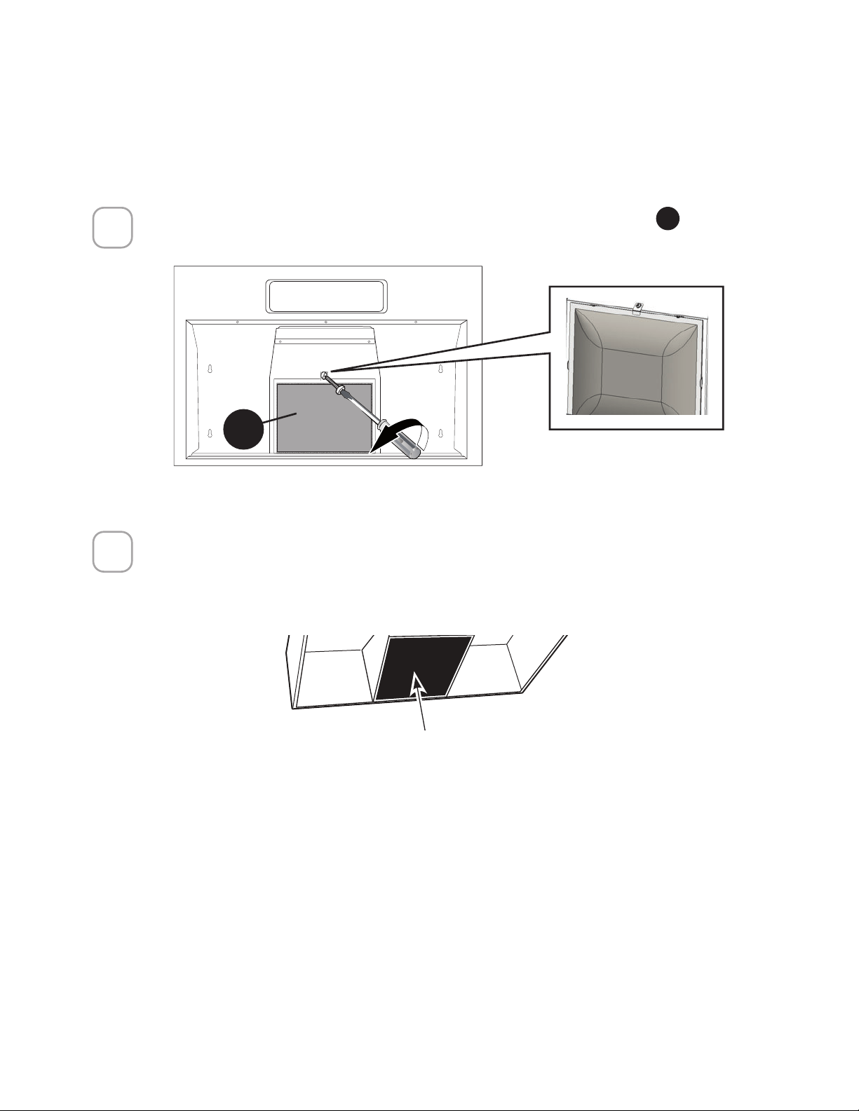
93
5HSODFHDEOHFKDUFRDOILOWHU
X
5HWLUHHOWRUQLOORFRPRVHPXHVWUD\VDTXHHO´OWURGHFDUEyQYHJHWDO
X
.
1
SUSTITUCIÓN DEL FILTRO DE CARBÓN ACTIVADO
Los Filtros de Carbón Activado no son lavables y no pueden ser regenerados, por lo que deben
ser reemplazados aproximadamente cada 4 meses de funcionamiento, o con mayor frecuencia
en caso de uso intensivo.
Póngase en contacto con Faber para obtener más información sobre el carbón vegetal de
UHSXHVWR12HQMXDJXHQLSRQJDORV´OWURVGHFDUEyQYHJHWDOHQXQODYDYDMLOODVDXWRPiWLFR
Tire hacia abajo del centro del borde delantero del filtro. El filtro se deslizará fuera de
las lengüetas de retención en la parte posterior. Para sustituirlo, deslice el borde po-
sterior del filtro en las lengüetas de sujeción y empuje el borde delantero hacia arriba
hasta que encaje en su sitio.
&RORTXHHO´OWUR\DVHJ~UHORFRQHOWRUQLOORUHWLUDGRDQWHULRUPHQWH
2
Filtro de carbón vegetal reemplazable
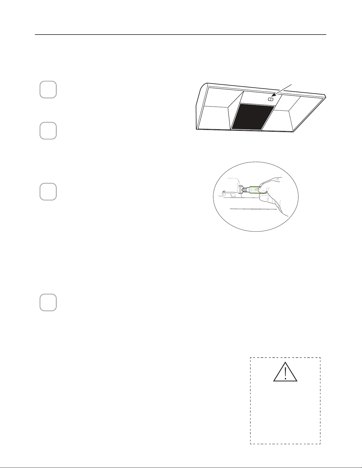
94
1
2
3
/LJKWFRYHU
4
!
SUSTITUCIÓN DE LA ILUMINACIÓN
Se sugiere la sustitución por una bombilla incandescente de tipo A15, E26, 40
vatios
Antes de intentar sustituir las luces,
asegúrese de que el interruptor de la
luz está apagado.
Retire la cubierta de la luz
presionando los lados con dos
dedos hasta que se suelten las
puntas laterales. Levante la cubierta
de la luz y deslícela hacia usted en
un solo movimiento.
Desenrosque la luz en el sentido
contrario a las agujas del reloj para
desbloquearla y sáquela. Sustituya
la lámpara por una nueva del mismo
tipo (incandescente estándar),
asegurándose de que el enchufe
esté correctamente insertado en la
carcasa del portalámparas.
Atención: Las bombillas pueden
estar calientes, espere unos
minutos antes de sustituirlas.
Para reemplazar la cubierta de
la luz, inserte la punta ubicada
en el extremo de la cubierta en
la abertura superior. Empuje
suavemente la cubierta hacia
arriba y presione los lados para
encajar las puntas laterales en
las aberturas laterales. Suéltela
y la cubierta se bloqueará en su
posición.
PRECAUCIÓN -
RIESGO DE
INCENDIO,
LÁMPARA
MÁXIMA DE 60
W TIPO A19
Cubierta de
la luz

95
DIAGRAMA DE CABLEADO
E
%/.
D
9/7
02725&';
:,5,1*
%2;
%/.
:+7
5('
E
5('
2))
%/.
D
%/.
*1'
:+7
+22',17(51$/&21752/
/$03
:+7
1
/,1(
9DF+]
%/.
/
%/.

96
GARANTÍA
GARANTÍA Y SERVICIO AL CONSUMIDOR FABER
Todos los productos Faber están garantizados contra cualquier defecto de materiales o mano de obra
para el comprador original por un período de 1 año a partir de la fecha de compra original (requiere
prueba de compra). Esta garantía cubre mano de obra y piezas de repuesto. Faber, a su elección, pue-
de reparar o reemplazar el producto o componentes necesarios para restaurar el producto en buenas
condiciones de trabajo. Para obtener el servicio de garantía, póngase en contacto con el distribuidor de
quien adquirió la campana extractora o con el distribuidor local de Faber. Si no puede identificar a un
distribuidor local de Faber, comuníquese con nosotros al (508) 358-5353 para obtener el nombre de
un distribuidor en su área.
Lo siguiente no está cubierto por la garantía de Faber:
1. Llamadas de servicio para corregir la instalación de su campana extractora, para instruirle sobre
cómo usar su campana extractora, para reemplazar o reparar fusibles de la casa o para corregir el
cableado de la casa o la plomería.
2. Llamadas de servicio para reparar o reemplazar las bombillas, fusibles o filtros de la campana ex-
tractora. Estas partes de consumibles están excluidas de la cobertura de la garantía.
3. Reparaciones, cuando su campana extractora se utiliza para uso doméstico distinto al normal.
4. Daños resultantes de accidente, alteración, mal uso, abuso, incendio, inundación, eventos naturales,
instalación incorrecta, instalación no conforme a los códigos eléctricos o de plomería o la documen-
tación de Faber, o uso de productos no aprobados por Faber.
5. Piezas de repuesto o costos de mano de obra de reparación para unidades operadas fuera de los
Estados Unidos o Canadá, incluyendo cualquier campana de cocina Faber no aprobada por UL o
C-UL.
6. Reparaciones a la campana resultantes de modificaciones no autorizadas a la misma.
7. Gastos de viaje y transporte para el servicio del producto en lugares remotos, y gastos de recogida
y entrega. Las campanas de cocina Faber deben ser reparadas en el hogar.
ESTA GARANTÍA NO PERMITE LA RECUPERACIÓN DE DAÑOS INCIDENTALES O CONSECUENTES,
INCLUYENDO, SIN LIMITACIÓN, DAÑOS DIRECTOS, INDIRECTOS, INCIDENTALES, ESPECIALES O
CONSECUENTES, LESIONES PERSONALES O MUERTE INCORRECTA O BENEFICIOS PERDIDOS. LA
GARANTÍA DE FABER SE LIMITA A LAS CONDICIONES ANTERIORES Y AL PERÍODO DE GARANTÍA
ESPECIFICADO AQUÍ Y ES EXCLUSIVA. EXCEPTO DADO LO EXPRESAMENTE ESPECIFICADO EN
ESTE ACUERDO, FABER RENUNCIA A TODAS LAS CONDICIONES, REPRESENTACIONES Y GARAN-
TÍAS EXPRESAS O IMPLÍCITAS INCLUYENDO, SIN LIMITACIÓN, CUALQUIER GARANTÍA IMPLÍCITA DE
COMERCIABILIDAD O ADECUACIÓN PARA UN PROPÓSITO PARTICULAR.
Esta garantía le otorga derechos legales específicos que pueden variar de estado a estado.
Modelo: _________________________ Número de serie ________________________


991.0676.427_02 - 220405 - D000000008483_01