LEVT30SS395
LEVT36SS395
Installation Instructions
Use and Care Information
Instructions d'installation
Utilisez et d'entretien
Instrucciones de instalación
Información de uso y cuidado
LEVANTE II

2
CONTENTS
Section Page
Important safety instructions 3
Range hood dimensions 6
Installation height requirements 7
Parts 8
Tools needed 9
Before installation remove shipping materials 10
Only for canadian market 11
Choose vertical or horizontal electrical connection knockout's 12
Venting method options-ducted or ductless 14
Non ducted recirculation option 15
Ducted - 7" round outlet 16
Ducted - 3 1/4" x 10" rectangular outlet on top 18
Ducted - 3 1/4" x 10" rectangular outlet rear 19
Choosing the mounting method 20
Mounting range hood on wall 21
Mounting range hood under the cabinet 25
Connecting electricity 27
Operating the controls 28
&DULQJIRU´OWHUV 29
Replacing lighting 31
Wiring diagram 32
Warranty 33

3
IMPORTANT SAFETY INSTRUCTIONS
READ AND SAVE THESE INSTRUCTIONS BEFORE YOU START
INSTALLING THIS RANGE HOOD
WARNING: - TO REDUCE THE RISK OF A RANGE TOP GREASE FIRE:
a) Never leave surface units unattended at high settings. Boilovers cause smoking and
greasy spillovers that may ignite. Heat oils slowly on low or medium setting.
E$OZD\VWXUQKRRG21ZKHQFRRNLQJDWKLJKKHDWRUZKHQµDPEHLQJIRRGLH&UHSHV
Suzette, Cherries Jubilee, Peppercorn Beef Flambé).
c) Clean ventilating fans frequently. Grease should not be allowed to accumulate on fan or
´OWHU
d) Use proper pan size. Always use cookware appropriate for the size of the surface element.
WARNING: - TO REDUCE THE RISK OF INJURY TO PERSONS IN THE EVENT OF A RANGE
TOP GREASE FIRE, OBSERVE THE FOLLOWING*:
D6027+(5)/$0(6ZLWKDFORVH´WWLQJOLGFRRNLHVKHHWRUPHWDOWUD\WKHQWXUQRIIWKH
EXUQHU%(&$5()8/7235(9(17%8516,IWKHµDPHVGRQRWJRRXWLPPHGLDWHO\
EVACUATE AND CALL THE FIRE DEPARTMENT.
b) NEVER PICK UP A FLAMING PAN - You may be burned.
c) DO NOT USE WATER, including wet dishcloths or towels - a violent steam explosion will
result.
d) Use an extinguisher ONLY if:
1. You know you have a Class ABC extinguisher, and you already know how to operate
it.
7KH´UHLVVPDOODQGFRQWDLQHGLQWKHDUHDZKHUHLWVWDUWHG
7KH´UHGHSDUWPHQWLVEHLQJFDOOHG
<RXFDQ´JKWWKH´UHZLWK\RXUEDFNWRDQH[LW
* Based on "Kitchen Firesafety Tips" published by NFPA
WARNING - TO REDUCE THE RISK OF FIRE OR ELECTRIC SHOCK, do not use this fan with
any solid-state speed control device.
WARNING - TO REDUCE THE RISK OF FIRE, ELECTRICAL SHOCK, OR INJURY TO PERSONS,
OBSERVE THE FOLLOWING:
1. Use this unit only in the manner intended by the manufacturer. If you have any questions,
contact the manufacturer.
2. Before servicing or cleaning unit, switch power off at service panel and lock the service
disconnecting means to prevent power from being switched on accidentally. When the
service disconnecting means cannot be locked, securely fasten a prominent warning
device, such as a tag, to the service panel.
CAUTION: For General Ventilating Use Only. Do Not Use To Exhaust Hazardous or Explo-
sive Materials and Vapors.
WARNING - TO REDUCE THE RISK OF FIRE, ELECTRICAL SHOCK, OR INJURY TO PERSONS,
OBSERVE THE FOLLOWING:
1. ,QVWDOODWLRQ:RUN$QG(OHFWULFDO:LULQJ0XVW%H'RQH%\4XDOL´HG3HUVRQV,Q$FFRU-
dance With All Applicable Codes And Standards, Including Fire-Rated Construction.
2. 6XI´FLHQWDLULVQHHGHGIRUSURSHUFRPEXVWLRQDQGH[KDXVWLQJRIJDVHVWKURXJKWKH
µXHFKLPQH\RIIXHOEXUQLQJHTXLSPHQWWRSUHYHQWEDFNGUDIWLQJ)ROORZWKHKHDWLQJ
equipment manufacturer's guideline and safety standards such as those published by
WKH1DWLRQDO)LUH3URWHFWLRQ$VVRFLDWLRQ1)3$DQGWKH$PHULFDQ6RFLHW\IRU+HDWLQJ
5HIULJHUDWLRQDQG$LU&RQGLWLRQLQJ(QJLQHHUV$6+5$(DQGWKHORFDOFRGHDXWKRULWLHV

4
ALL WALL AND FLOOR OPENINGS WHERE THE RANGE HOOD IS INSTALLED
MUST BE SEALED.
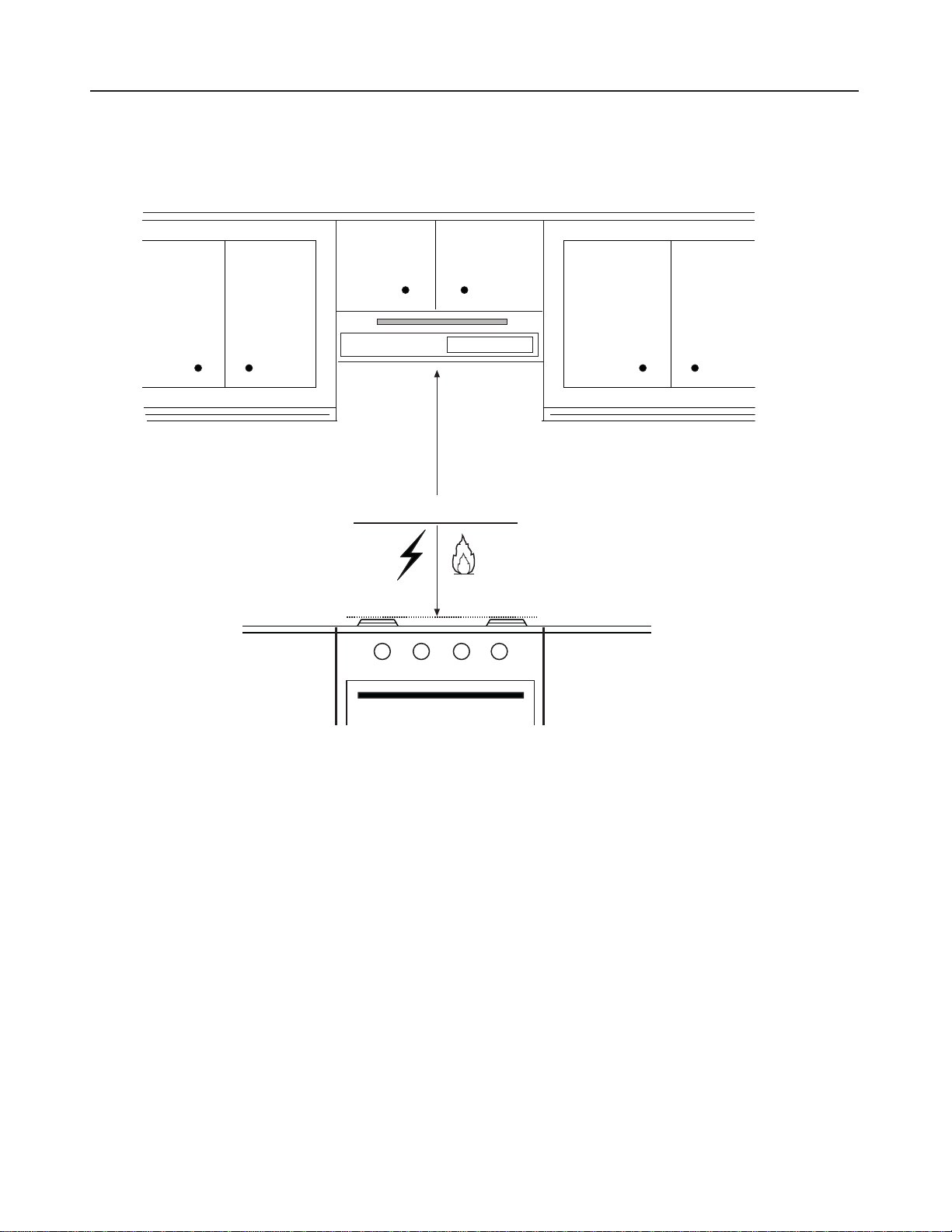
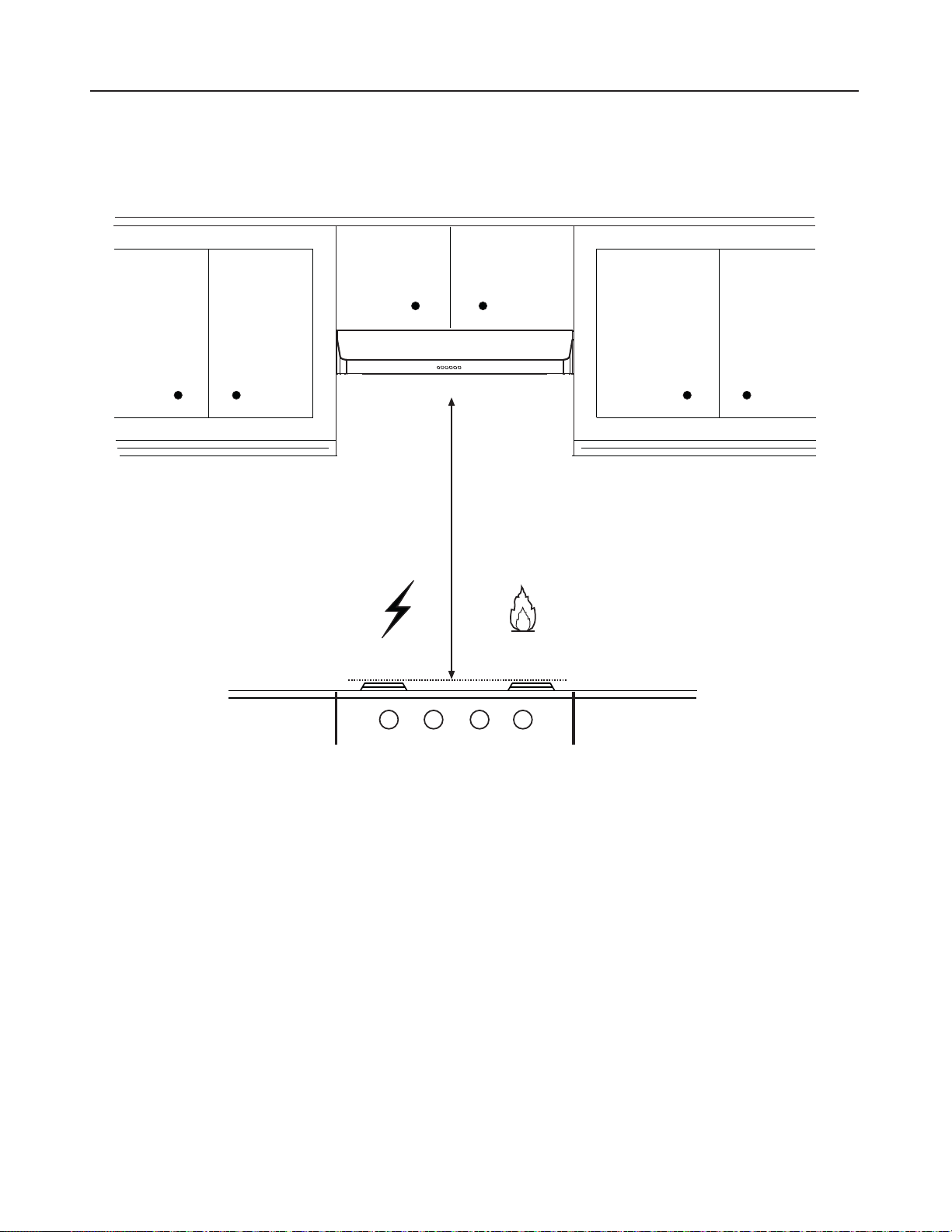
This Range Hood requires at least 24" of clearance between the bottom of the Range
Hood and the cooking surface or countertop. This hood has been approved by UL at this
distance from the cooktop.
This minimum clearance may be higher depending on local building codes. For gas cooktops
and combination ranges, a minimum of 30" is recommended and may be required.
Overhead cabinets on both sides of this unit must be a minimum of 18" above the cooking
surface or countertop. Consult the cooktop or range installation instructions given by the
manufacturer before making any cutouts.
MOBILE HOME INSTALLATION The installation of this Range Hood must conform to the
Manufactured Home Construction and Safety Standards, Title 24 CFR, Part 3280 (formerly
Federal Standard for Mobile Home Construction and Safety, Title 24, HUD, Part 280). See
Electrical Requirements"
• Venting system MUST terminate outside the home.
• DO NOT terminate the ductwork in an attic or other enclosed space.
• DO NOT use 4" laundry-type wall caps.
• Flexible-type ductwork is not recommended.
• DO NOTREVWUXFWWKHµRZRIFRPEXVWLRQDQGYHQWLODWLRQDLU
)DLOXUHWRIROORZYHQWLQJUHTXLUHPHQWVPD\UHVXOWLQD´UH
WARNING
!
VENTING REQUIREMENTS
Determine which venting method is best for your application. Ductwork can extend either
through the wall or the roof.
The length of the ductwork and the number of elbows should be kept to a minimum to
SURYLGHHI´FLHQWSHUIRUPDQFH7KHVL]HRIWKHGXFWZRUNVKRXOGEHXQLIRUP'RQRWLQVWDOO
two elbows together. Use duct tape to seal all joints in the ductwork system. Use caulking
WRVHDOH[WHULRUZDOORUµRRURSHQLQJDURXQGWKHFDS
Flexible ductwork is not recommended. Flexible ductwork creates back pressure and air
turbulence that greatly reduces performance.
0DNHVXUHWKHUHLVSURSHUFOHDUDQFHZLWKLQWKHZDOORUµRRUIRUH[KDXVWGXFWEHIRUHPDNLQJ
cutouts. Do not cut a joist or stud unless absolutely necessary. If a joist or stud must be cut,
then a supporting frame must be constructed.
WARNING - To Reduce The Risk Of Fire, Use Only Metal Ductwork.
&$87,217RUHGXFHULVNRI´UHDQGWRSURSHUO\H[KDXVWDLUEHVXUHWRGXFWDLURXWVLGH
– Do not vent exhaust air into spaces within walls or ceilings or into attics, crawl spaces,
or garages.
Cold Weather installations
$QDGGLWLRQDOEDFNGUDIWGDPSHUVKRXOGEHLQVWDOOHGWRPLQLPL]HEDFNZDUGFROGDLUµRZDQGDQRQPH-
tallic thermal break should be installed to minimize conduction of outside temperatures as part of the
vent system. The damper should be on the cold air side of the thermal break. The break should be as
close as possible to where the vent system enters the heated portion of the house.
3. When cutting or drilling into wall or ceiling, do not damage electrical wiring and other
hidden utilities.
4. Ducted fans must always be vented to the outdoors.
5
ELECTRICAL REQUIREMENTS
A 120 volt, 60 Hz AC-only electrical supply is required on a separate 15 amp fused circuit.
A time-delay fuse or circuit breaker is recommended. The fuse must be sized per local
FRGHVLQDFFRUGDQFHZLWKWKHHOHFWULFDOUDWLQJRIWKLVXQLWDVVSHFL´HGRQWKHVHULDOUDWLQJ
SODWHORFDWHGLQVLGHWKHXQLWQHDUWKH´HOGZLULQJFRPSDUWPHQW
ELECTRICAL INSTALLATION WITH WIRING BOX
THIS UNIT MUST BE CONNECTED WITH COPPER WIRE ONLY. Wire sizes must conform
WRWKHUHTXLUHPHQWVRIWKH1DWLRQDO(OHFWULFDO&RGH$16,1)3$ODWHVWHGLWLRQDQGDOO
local codes and ordinances. Wire size and connections must conform with the rating of
the appliance. Copies of the standard listed above may be obtained from:
National Fire Protection Association
Batterymarch Park
Quincy, Massachusetts 02269
This appliance should be connected directly to the fused disconnect (or circuit breaker)
WKURXJKµH[LEOHDUPRUHGRUQRQPHWDOOLFVKHDWKHGFRSSHUFDEOH$OORZVRPHVODFNLQ
the cable so the appliance can be moved if servicing is ever necessary. A UL Listed,
FRQGXLWFRQQHFWRUPXVWEHSURYLGHGDWHDFKHQGRIWKHSRZHUVXSSO\FDEOHDW
the appliance and at the junction box).
:KHQPDNLQJWKHHOHFWULFDOFRQQHFWLRQFXWDKROHLQWKHZDOO$KROHFXWWKURXJK
wood must be sanded until smooth. A hole through metal must have a grommet.
• Electrical ground is required on this Range Hood.
• If cold water pipe is interrupted by plastic, nonmetallic gaskets or other
materials, DO NOT use for grounding.
• DO NOT ground to a gas pipe.
• DO NOT have a fuse in the neutral or grounding circuit. A fuse in the neutral
or grounding circuit could result in electrical shock.
&KHFNZLWKDTXDOL´HGHOHFWULFLDQLI\RXDUHLQGRXEWDVWRZKHWKHUWKH5DQJH
Hood is properly grounded.
)DLOXUHWRIROORZHOHFWULFDOUHTXLUHPHQWVPD\UHVXOWLQD´UH
WARNING
6
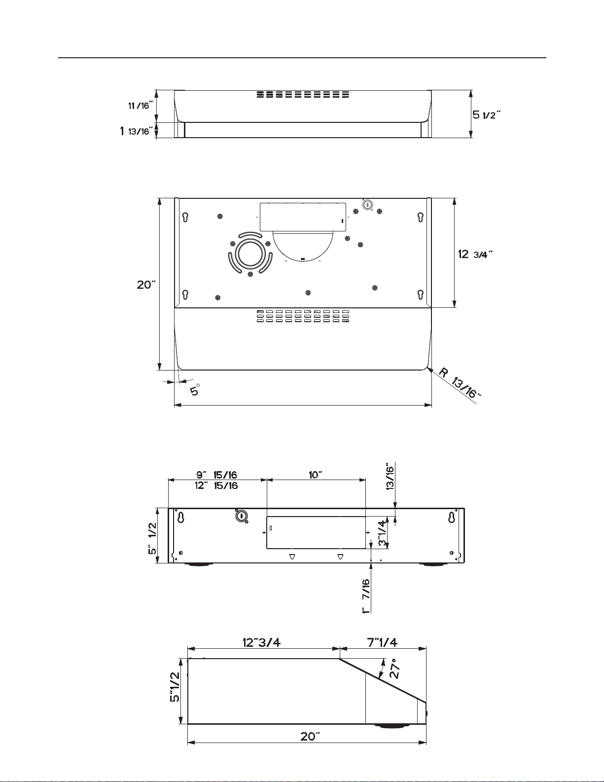
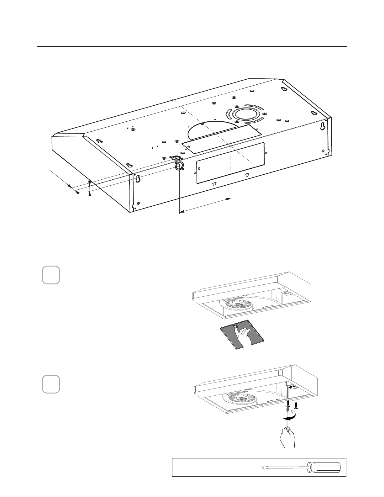
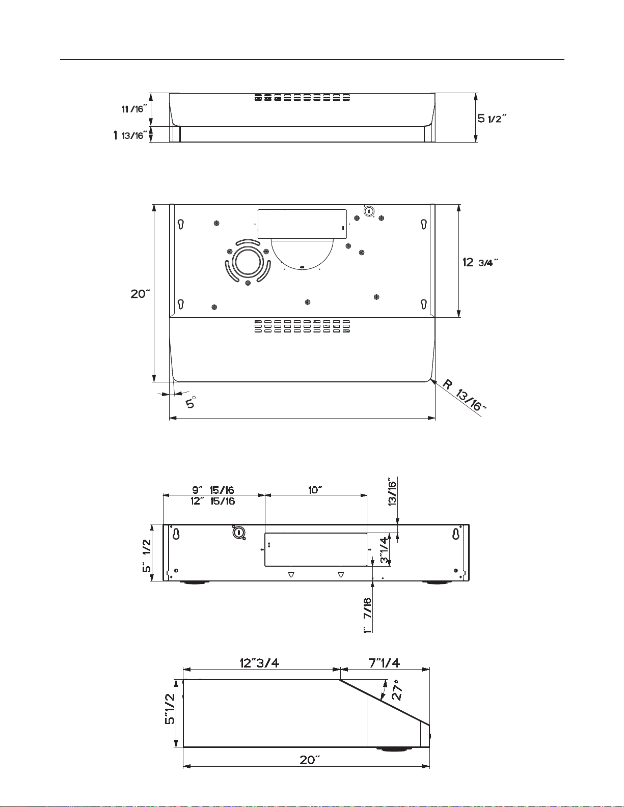
RANGE HOOD DIMENSIONS
3
29 15/16” - 35 15/16”
30" 36"
30"
36"
7
MIN. 24" OVER ELECTRIC / MIN. 30" OVER GAS
INSTALLATION HEIGHT REQUIREMENTS
Min. 24" - 30"
8
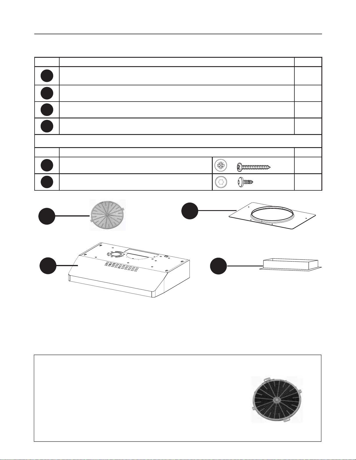
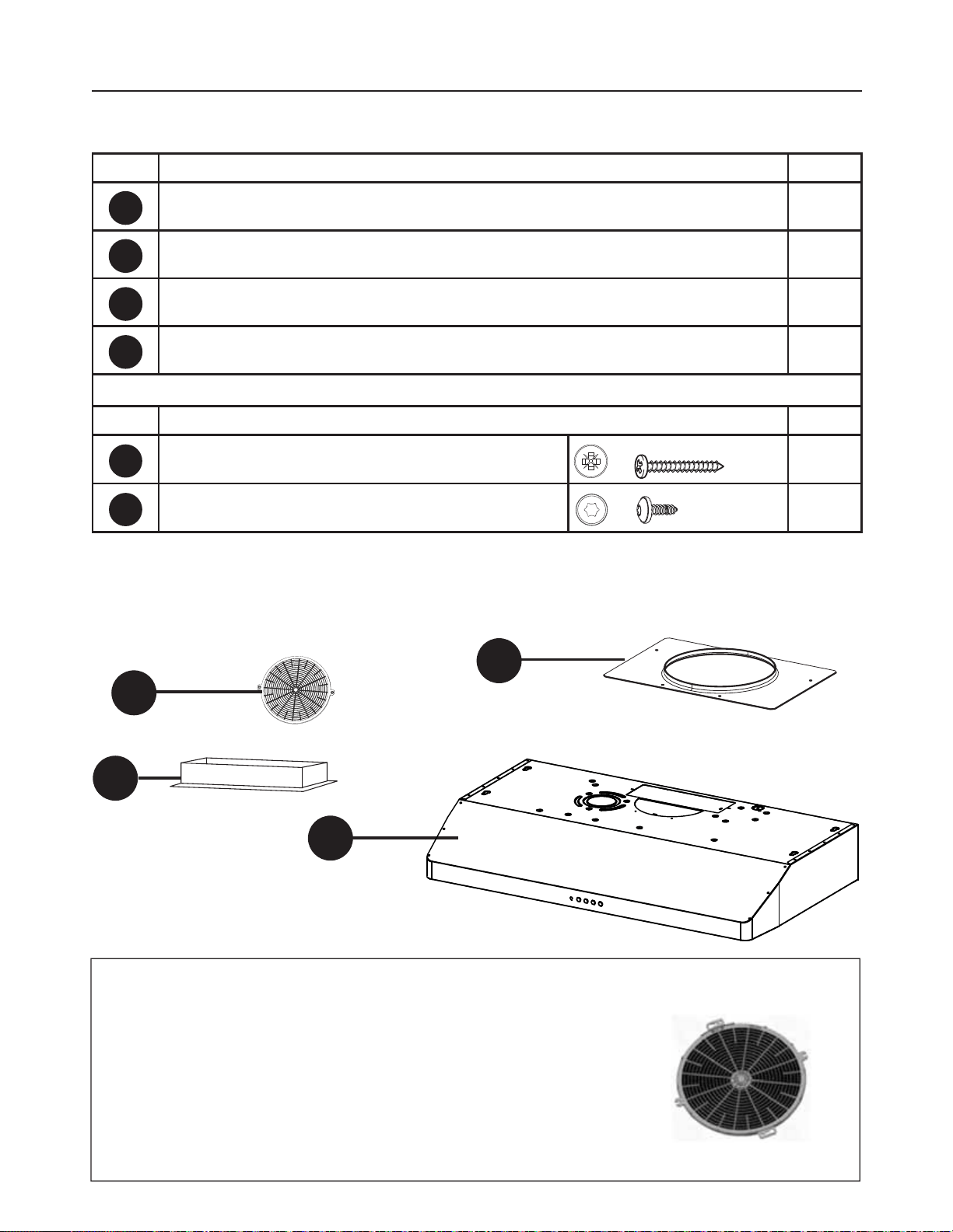
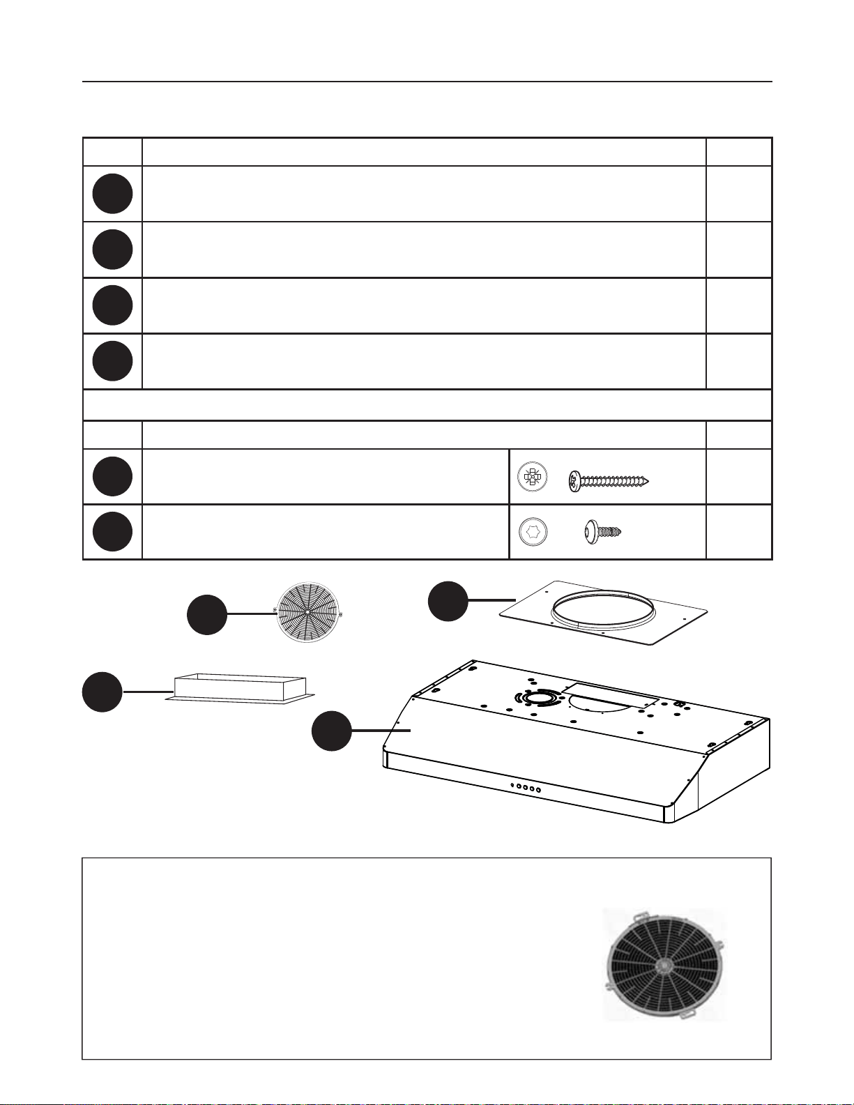
PARTS
REF. PART
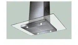
A
Hood body – Includes Controls, Light, Filters, Blower 1
B
Damper ([)1
C
7" Round Flange 1
D
Grid (Only for Canadian Market) 1
REF
PART
E
3R]L6FUHZV[
4
F
7RU[6FUHZV[
4
PARTS INCLUDED
C
B
A
D
Available Accessories
Activated Charcoal Filter (FILTER5)
Note: The Charcoal Filter is attached with two screws
(See page 15 and Figure C).
The Charcoal Filters must be purchased with only Faber
authorized dealers.
Wireless Remote Control-REMCTRL2
9
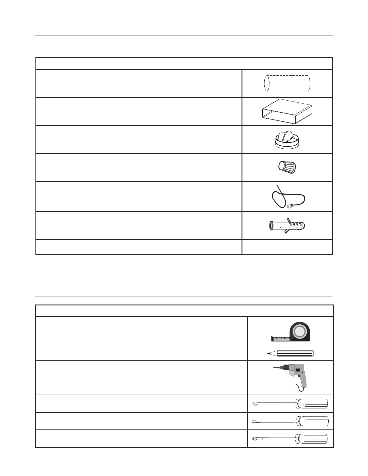
PARTS NEEDED
3$576FRQW
PART
7" Round Metal Ductwork
[5HFWDQJXODU'XFWZRUN
7" Damper
Wire connectors.
Power Supply Cable.
-
Drywall plugs or other suitable wall fasteners based on
your installation.
:DOO&DS5RRI&DS1HHGVWREHSXUFKDVHGVHSDUDWHO\
TOOLS NEEDED
TOOL
Tape Measure
Pencil
(OHFWULF'ULOOZLWK'ULOO%LW
Phillips Screwdriver
Torx Screwdriver
Pozi Screwdriver

10
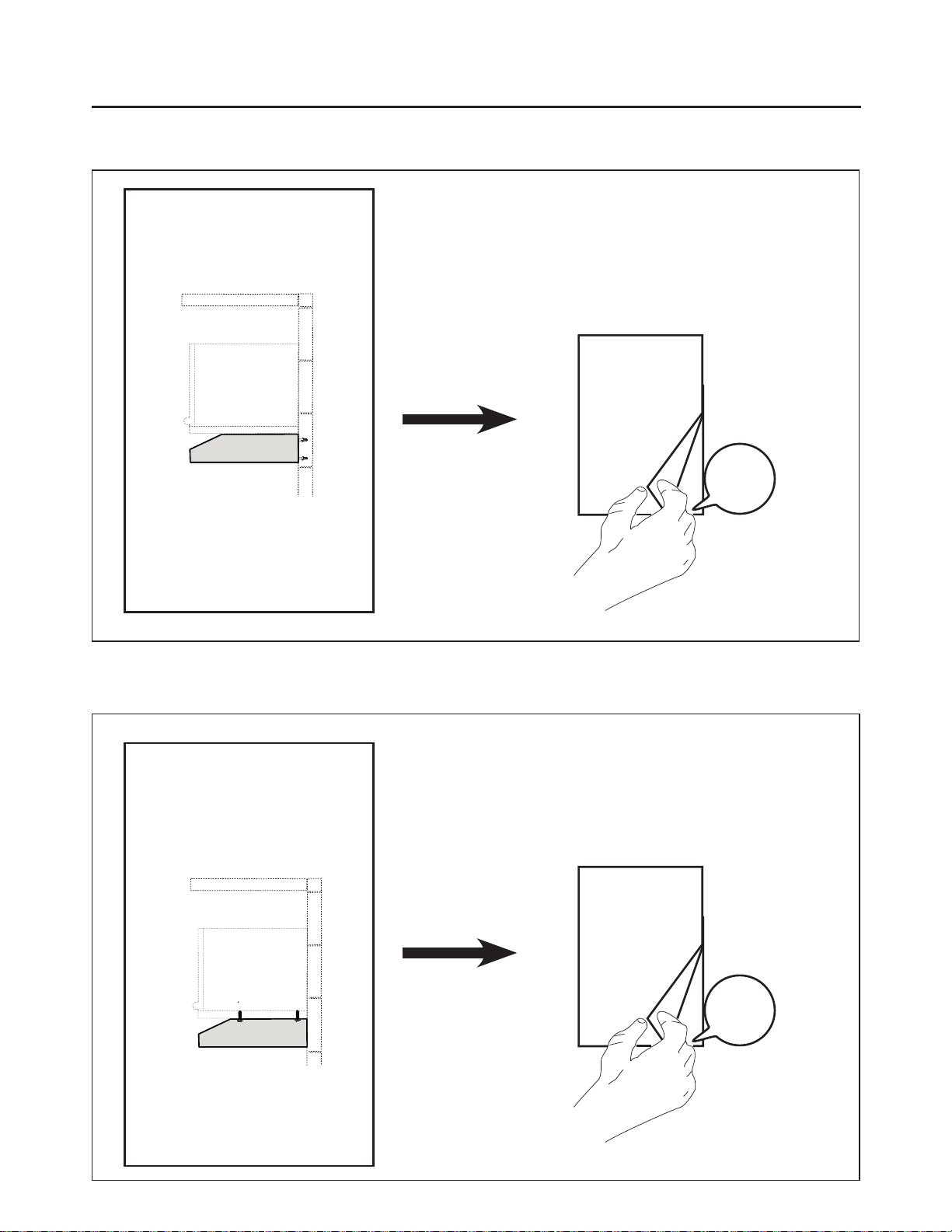
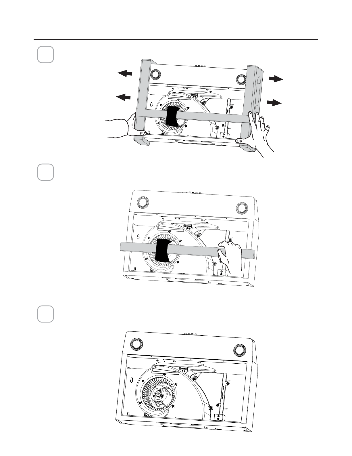
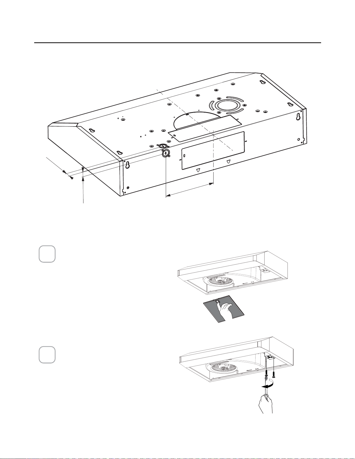
BEFORE INSTALLATION REMOVE SHIPPING
MATERIALS
Remove the side packaging.
Remove the foam packaging and wood bar.
1
2
3
Ready for Installation.
Caution: Do not
pick up hood using
the wood bar
11
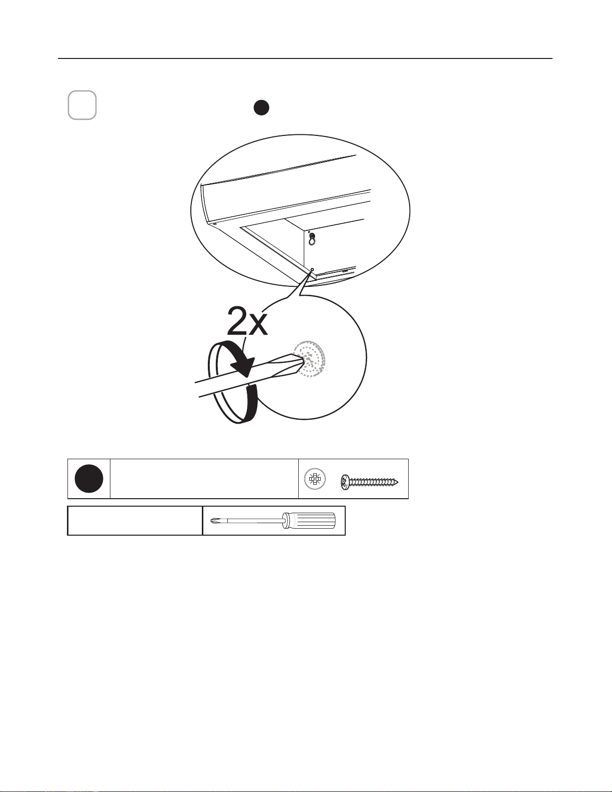
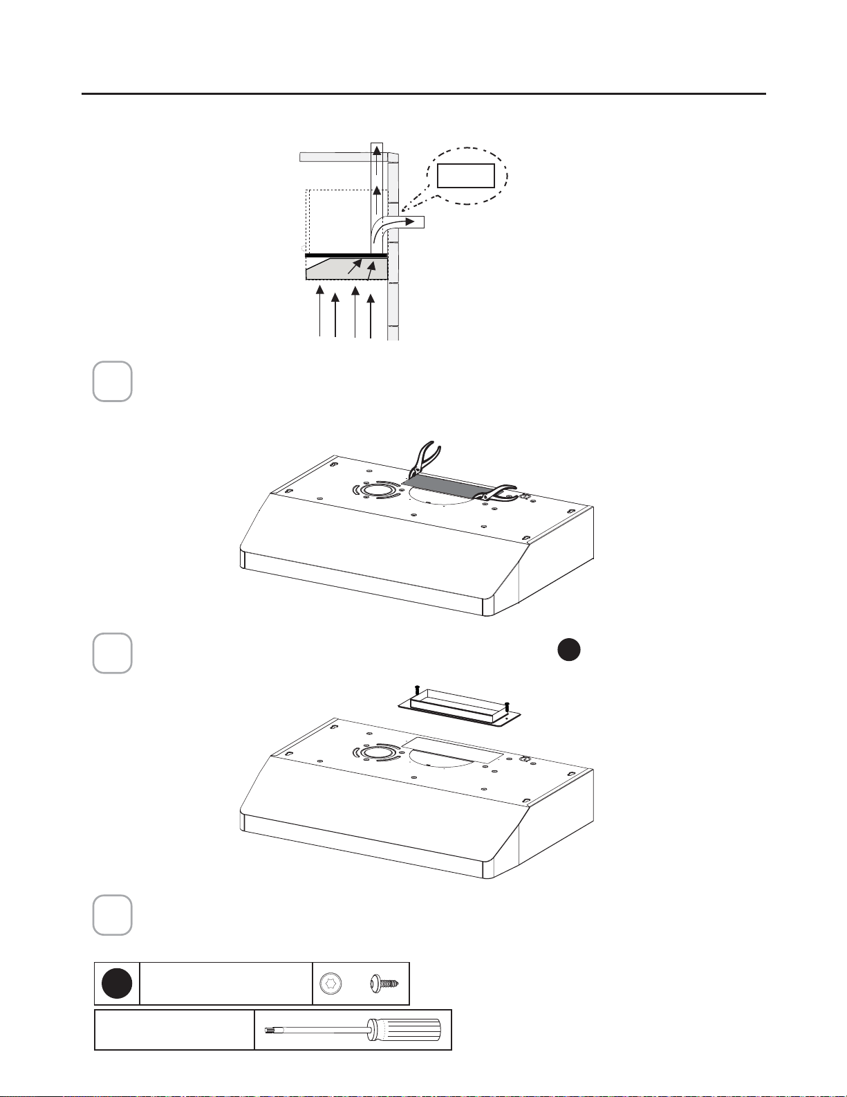
ONLY FOR CANADIAN MARKET
1
2
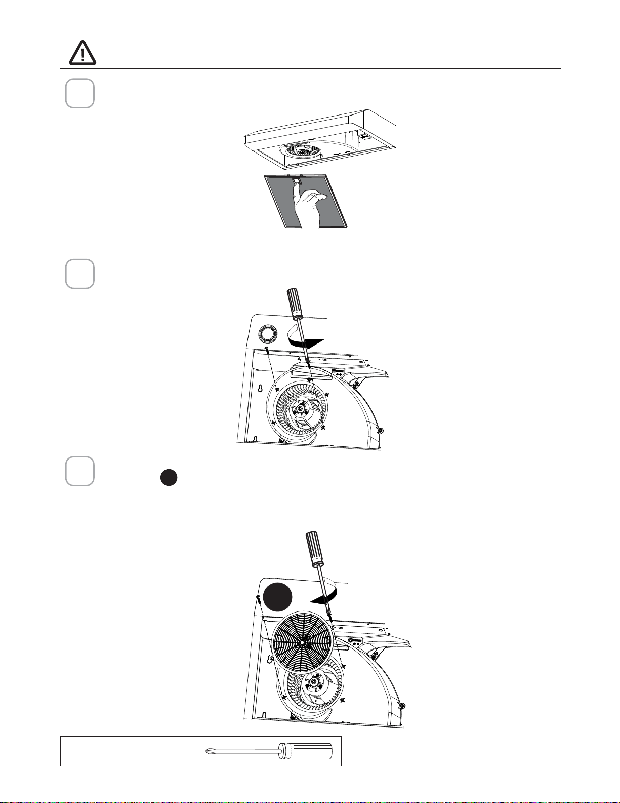
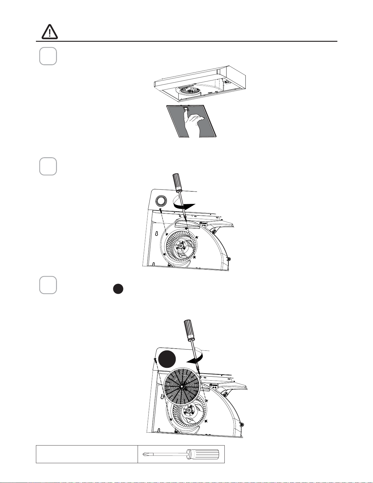
For ducted installations only:
5HPRYHWKH´OWHUVRQHDWDWLPHE\SXVKLQJWRZDUGVWKHEDFNRIWKHKRRGDQG
pulling down at the same time.
Install the screws as pictured.
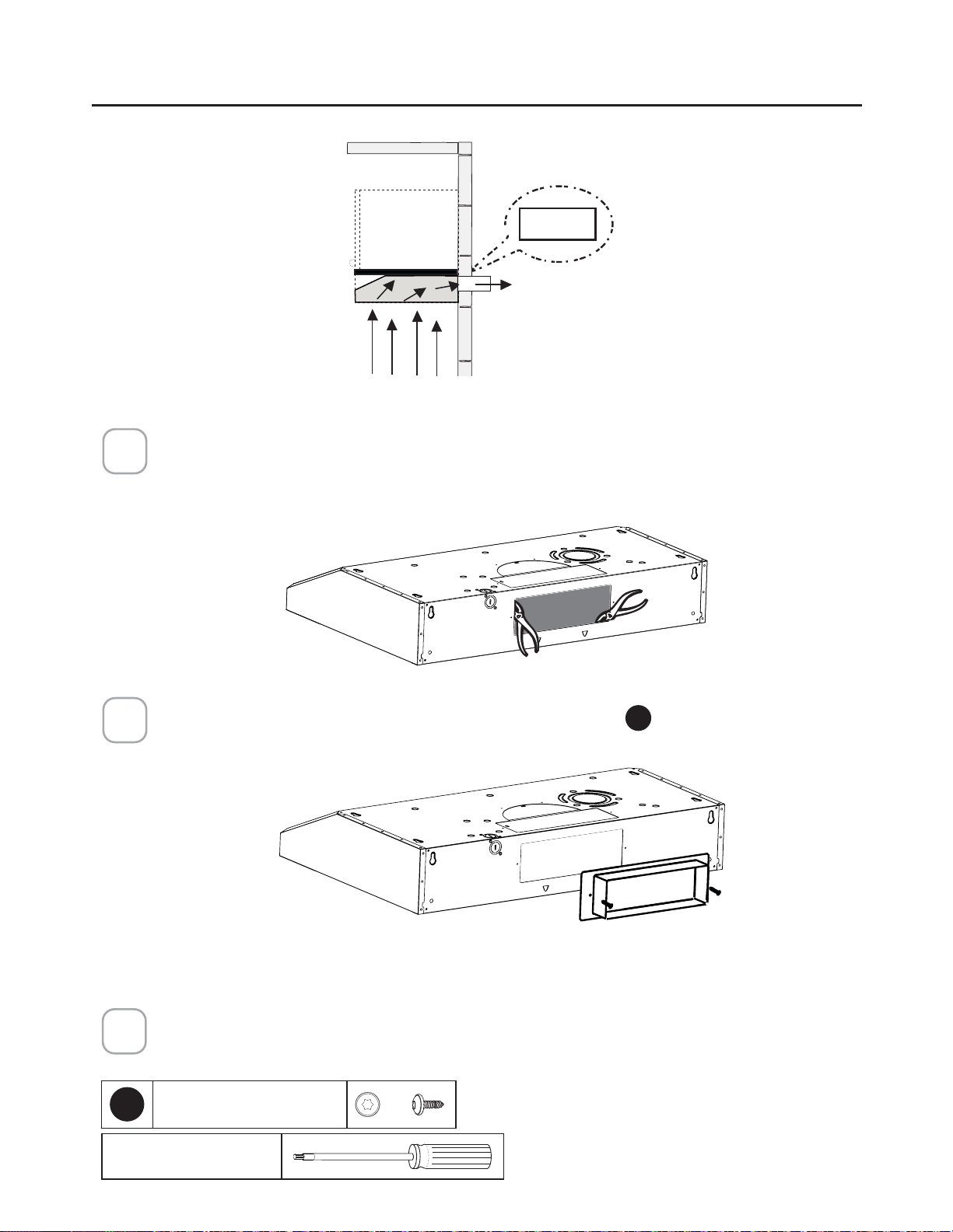
Install Grid
D
with the two screws removed from step 2. Screw the protection
grid into the location shown in the picture below. (The correct location has a
rectangular cut out to accommodate the grid.)
7DNHFDUHWRVFUHZWKHJULGFRPSOHWHO\µXVKWRDYRLGXQZDQWHGQRLVH
Remove the screws as pictured.
Remove two of the screws from the motor assembly housing as pictured.
3
Phillips Screwdriver
D
12
5HPRYHWKH´OWHUVRQHDW
a time by pushing them
towards the back of the
hood and pulling down at
the same time.
Remove the wiring box
cover by unscrewing
the 2 screws.
Preparing the hood for electrical knockouts
7" 1/2
13/16"
13/16"
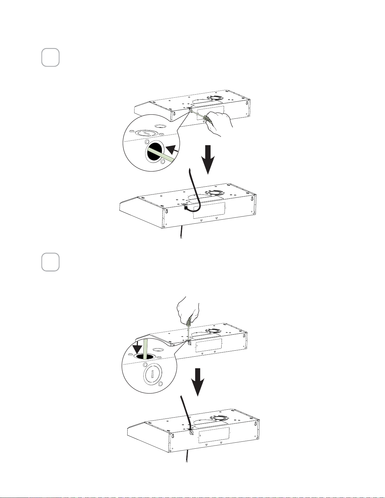
CHOOSE VERTICAL OR HORIZONTAL
ELECTRICAL CONNECTION KNOCKOUT'S
1
2
Phillips Screwdriver
=

13
5HDU+ROH+RUL]RQWDO
Choose the rear hole for the electric connection and break with a screwdriver or other
tool.
During the installation thread Power Supply Cable through this hole.
3
7RS+ROH9HUWLFDO
Choose the top hole for the electric connection and break with a screwdriver or
other tool.
During the installation thread Power Supply Cable through this hole.
4
14
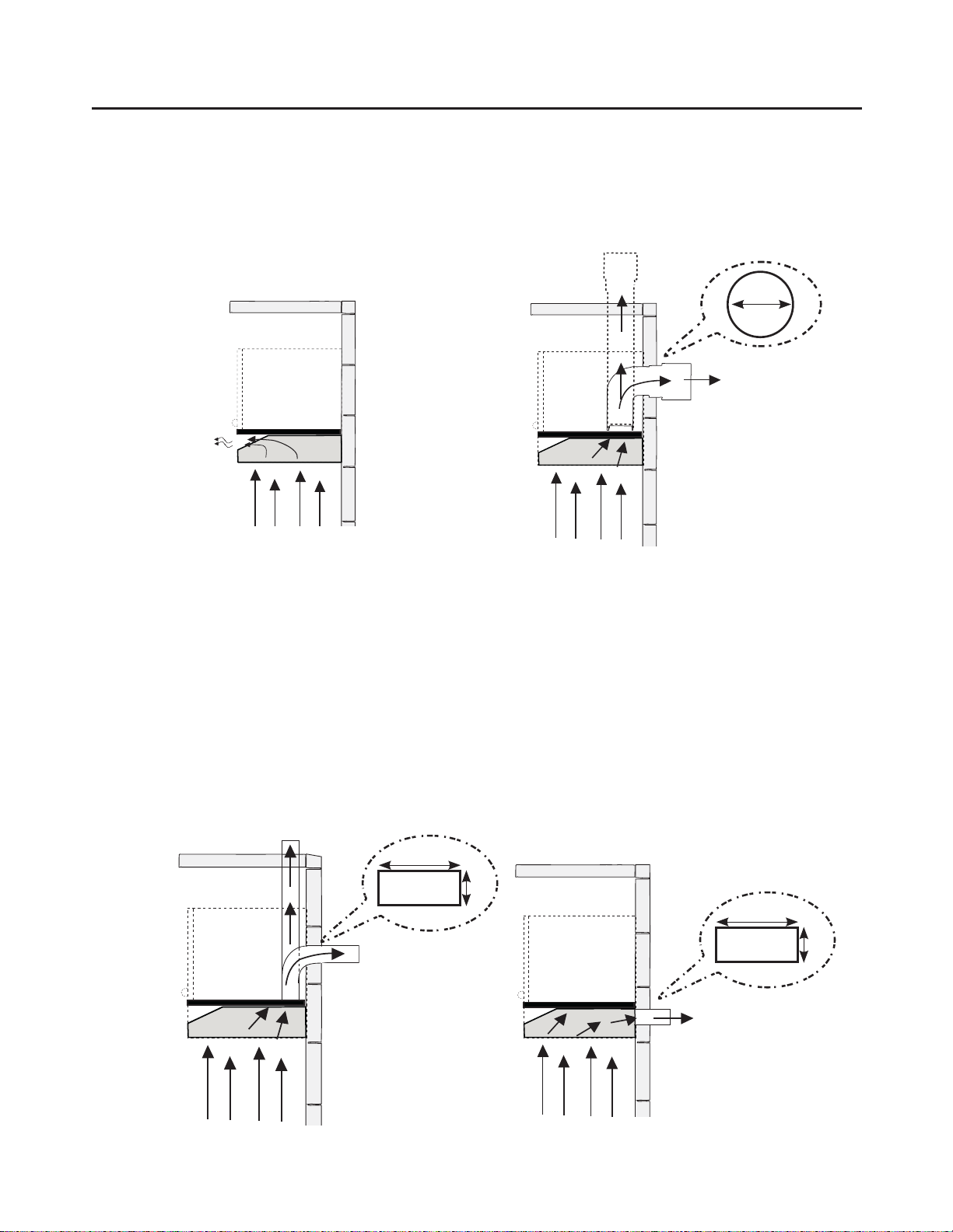
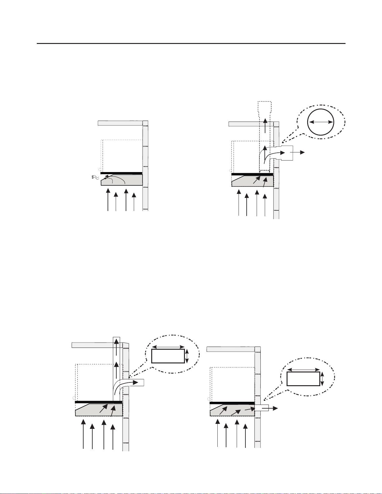
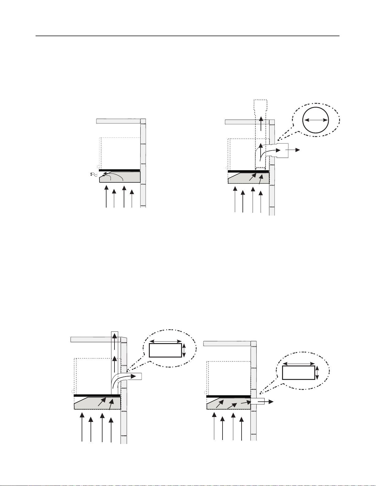
VENTING METHOD OPTIONS-DUCTED OR
DUCTLESS
DUCTED WITH 7" ROUND OUTLET:
– Vertical
– Horizontal
10"
3 1/4"
10"
3 1/4"
Rear
Top
7"
Rear
Top
Go to page 16
Go to page 18
DUCTED WITH 3 1/4" X 10" RECTANGULAR OUTLET
– Vertical
– Horizontal
Go to page 15
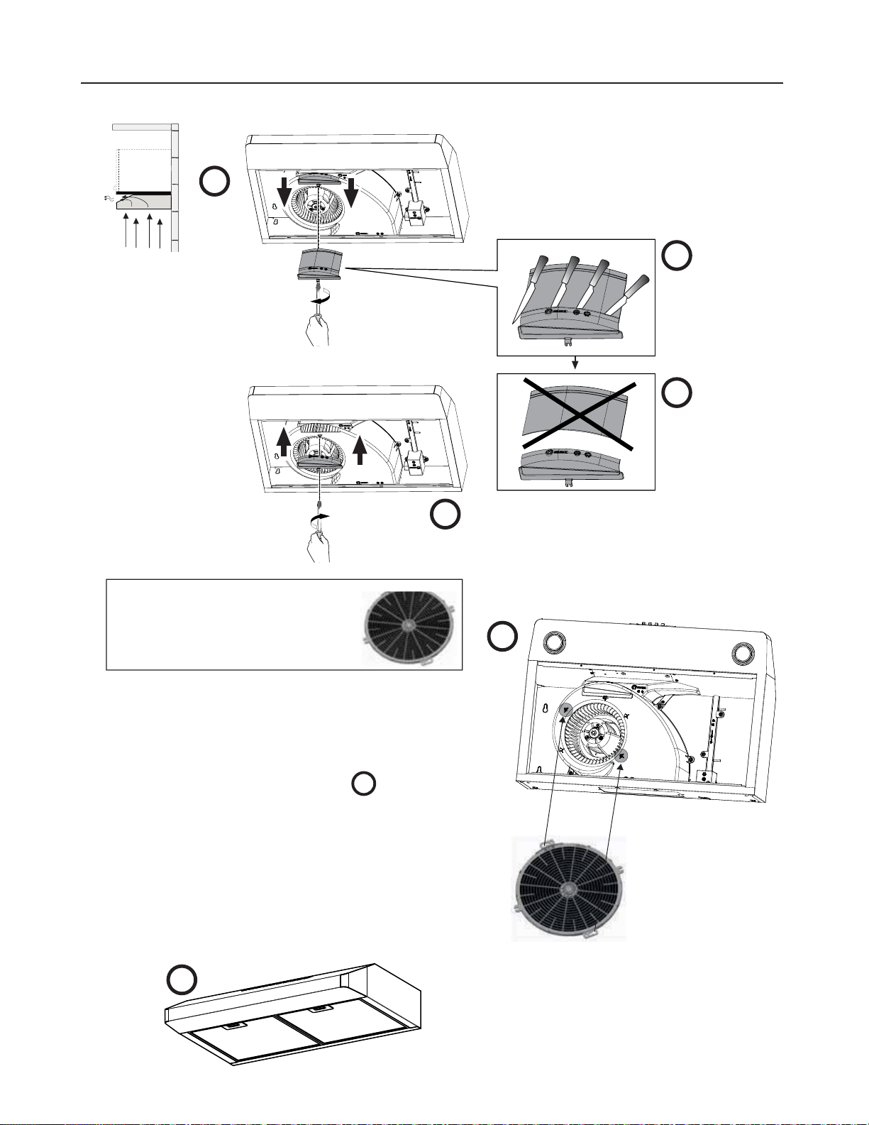
NON DUCTED - RECIRCULATION
OPTION
Requires
purchase
of
Activated
Charcoal
Accessory
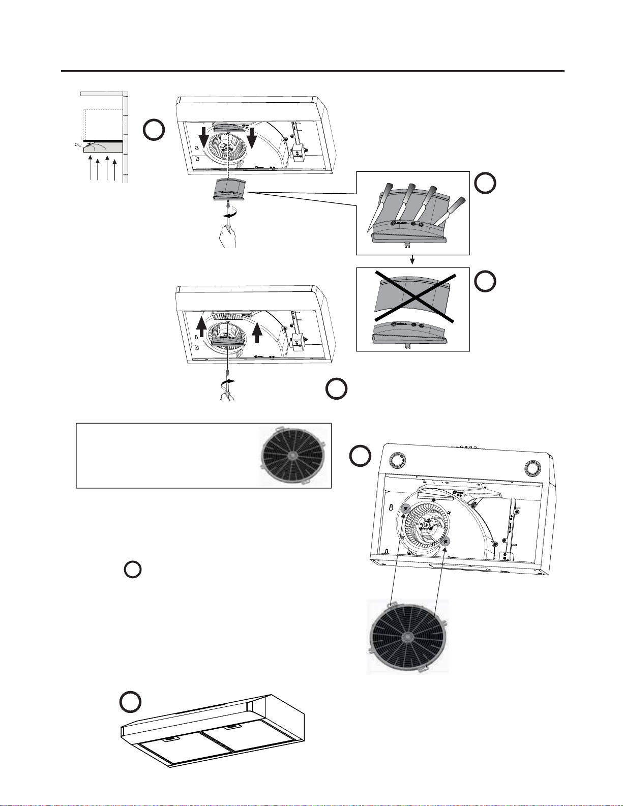
15
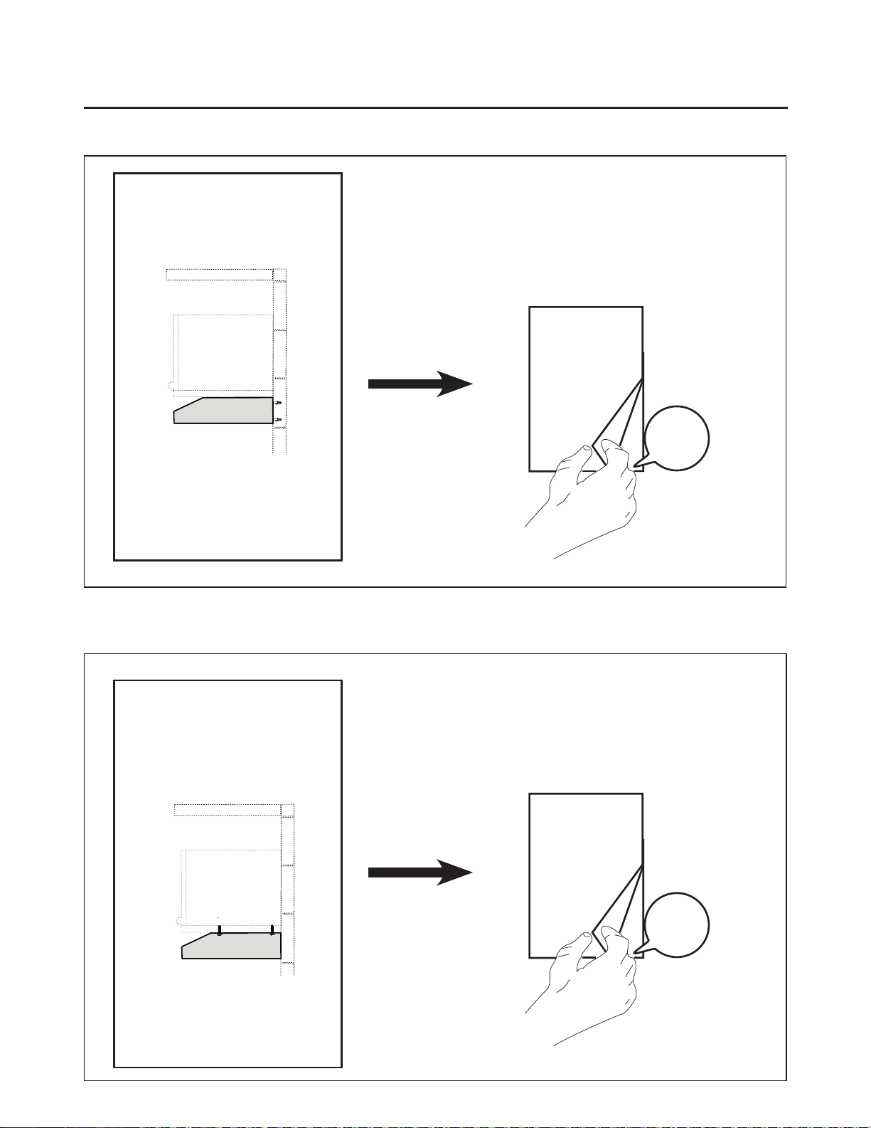
b1
a
b2
Remove the indicated blower cover
(do not discard the screw).
Reinstall the existing Grease Filters
after installing the Activated Charcoal
Filter before operating hood.
5HLQVWDOOWKHPRGL´HGEORZHUFRYHU
with the same screw.
Cut the
cover
where
indicated in
picture b1.
'LVFDUG
Recycle
upper
pieces of
blower
cover.
d
b3
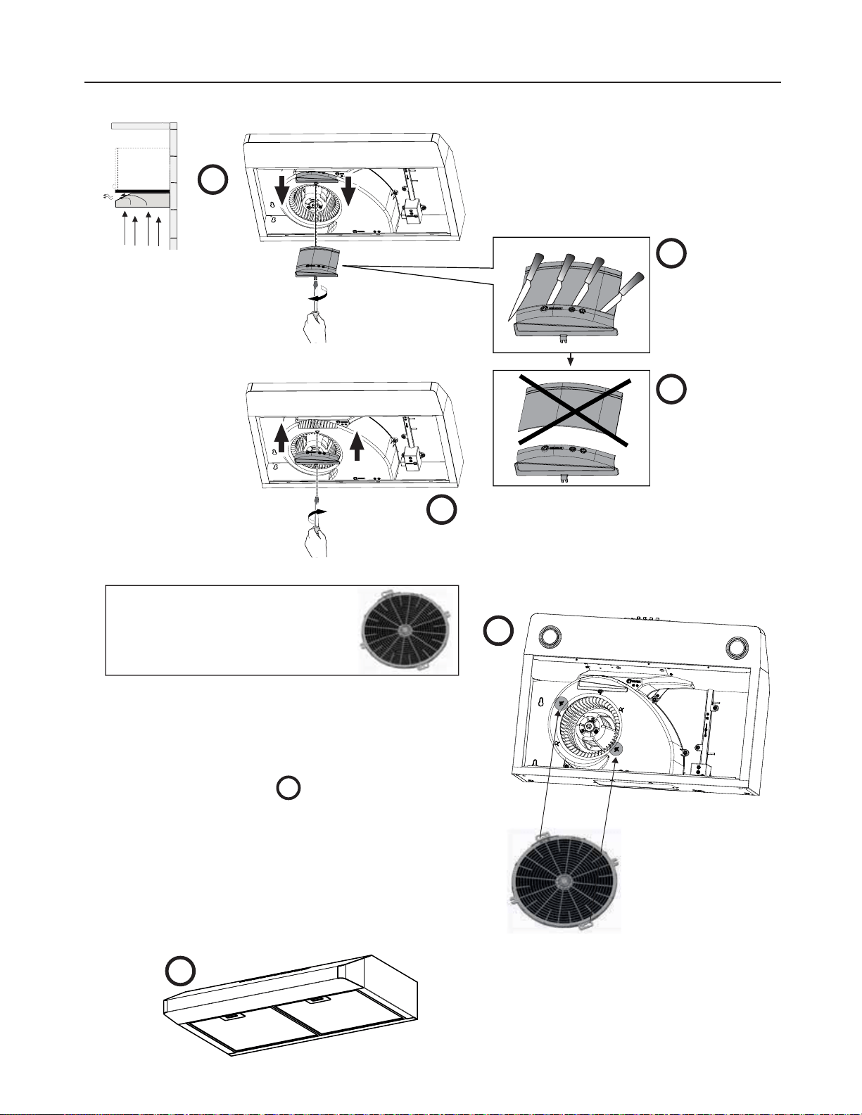
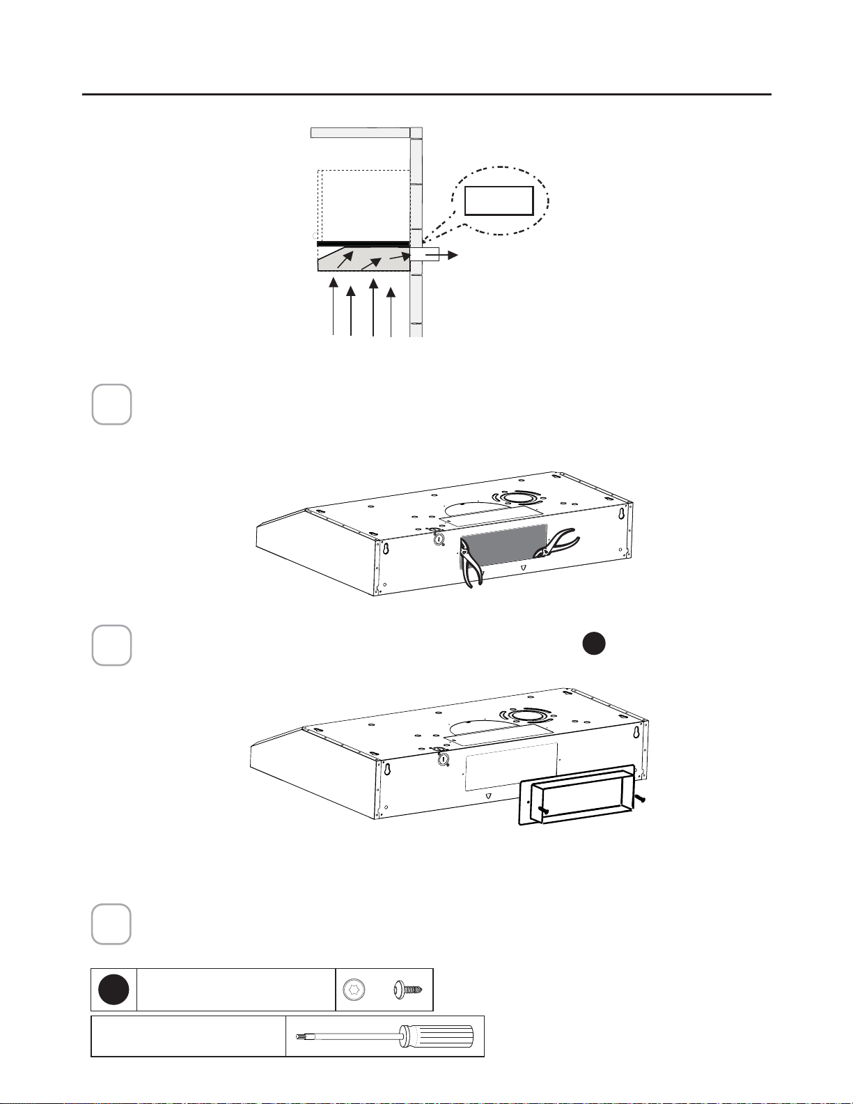
NON DUCTED RECIRCULATION OPTION
Go to page 20
Required Activated Charcoal
Filter Accessory - (FILTER5)
purchased separately.
c
Non Ducted installations only:
1. Remove the two screws located on the motor
housing in the location indicated.
3ODFHWKHFKDUFRDO´OWHUZLWKWKHWDEVDJDLQVW
the blower housing in the location indicated on
´JXUH
c
. The front side of the FILTER5 will
have the keyhole mounting on the top surface
RIWKH´OWHU$OD\HURIFKDUFRDOZLOOEHYLVLEOH
through the grills.
3. Use the two screws removed earlier to attach
the FILTER5 in place.
NOTE: For Non ducted installations the Canadian
Grid should NOT be used.

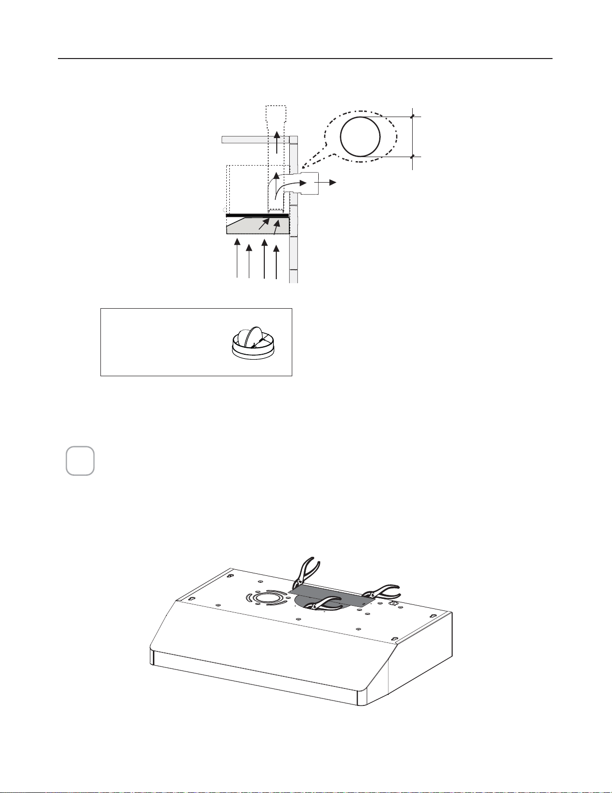
16
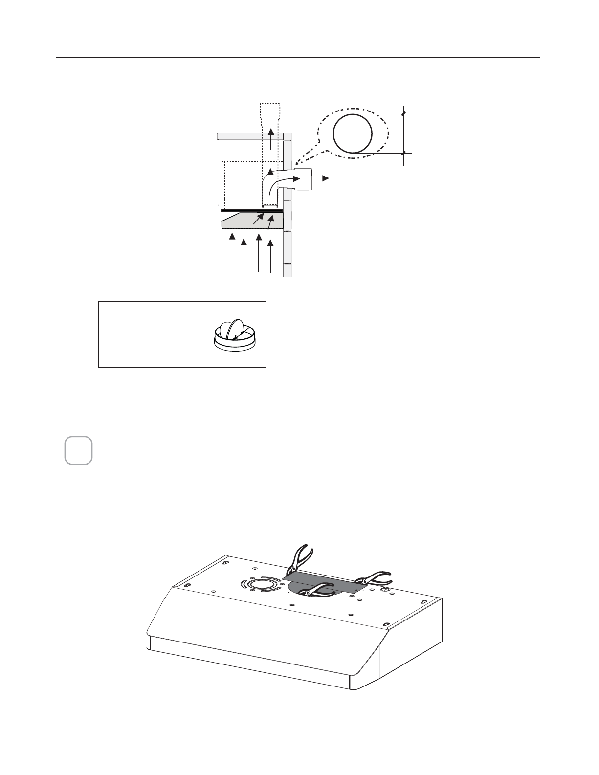
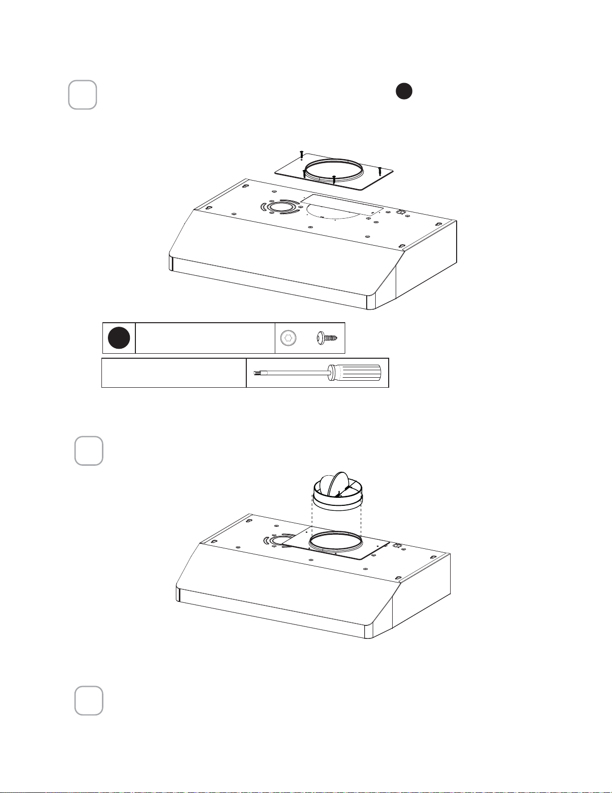
DUCTED - 7" ROUND OUTLET
Cut where indicated.
Remove both the rectangular and semicircle areas with metal shears.
Rear
Top
7"
Required; 7" Round
Damper purchase
separately.
1
Caution: If an elbow
is required, do it
as far away from
the hood's exhaust
opening as possible.
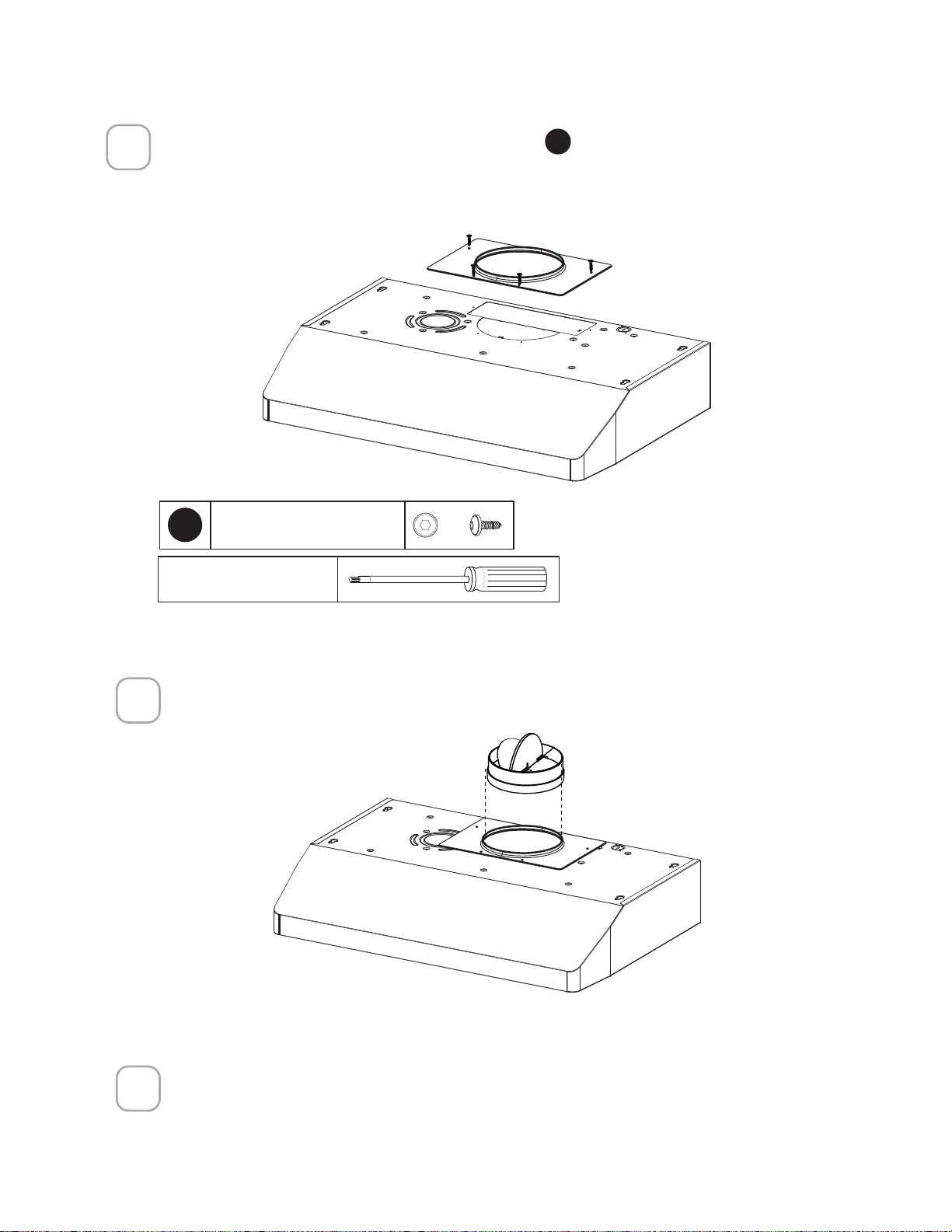
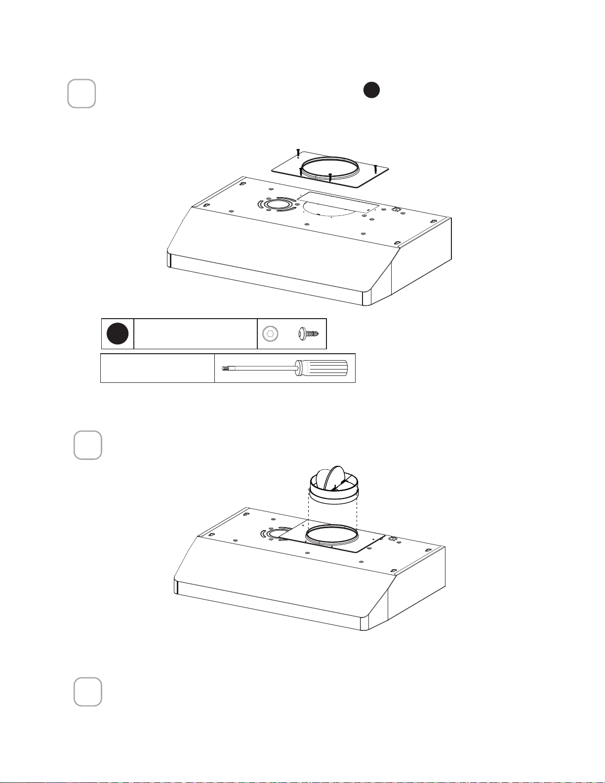
17
Install the Flange with Flange transition screws
F
.
Install 7" Round Damper purchased separately. Secure damper with foil duct tape.
Connect the 7" Round Metal Ductwork to the Roof or Wall Cap purchased separately
and then attach ductwork.
2
3
Torx Screwdriver
NOTE: The Flange must be mounted with the lip facing upward.
2QO\XVHWKHVFUHZVSURYLGHGIRUWKHµDQJH
F
7RU[6FUHZV[
4
Go to page 20

18
Choose the rectangular upper air outlet or rectangular rear air outlet and cut where
indicated.(See page 18 for Rear Outlet)
Install the included rectangular air outlet with two screws
F
.
Connect the metal ductwork to the Roof or Wall Cap purchased separately and
then attach ductwork.
Rear
Top
Top
3
1/4
" x 10"
DUCTED - 3 1/4" X 10" RECTANGULAR OUTLET
ON TOP
1
2
3
Torx Screwdriver
F
7RU[6FUHZV[
Caution: If an elbow is required,
do it as far away from the
hood's exhaust opening as
possible.

19
Go to page 20
Rear
Rear
3
1/4
" x 10"
Use the rear air outlet and cut where indicated.
Install the included rectangular air outlet with two screws
F
.
1
2
Torx Screwdriver
F
7RU[6FUHZV[
DUCTED - 3 1/4" X 10" RECTANGULAR OUTLET
REAR
Caution: If an elbow is required,
do it as far away from the
hood's exhaust opening as
possible.
Connect the metal ductwork to the Roof or Wall Cap purchased separately and
then attach ductwork.
3
20
CHOOSING THE MOUNTING METHOD
Installation for Mounting on the Wall
Installation for Mounting to the cabinet
Page
21
Page
25
21
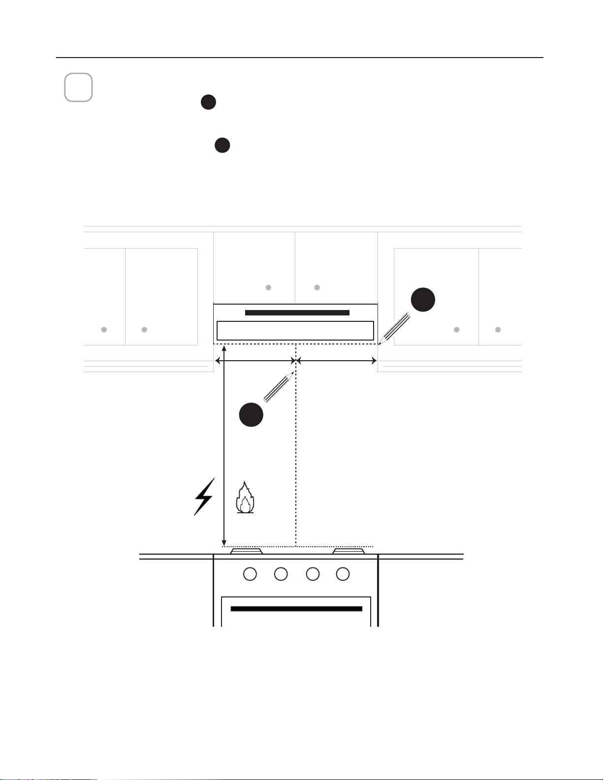
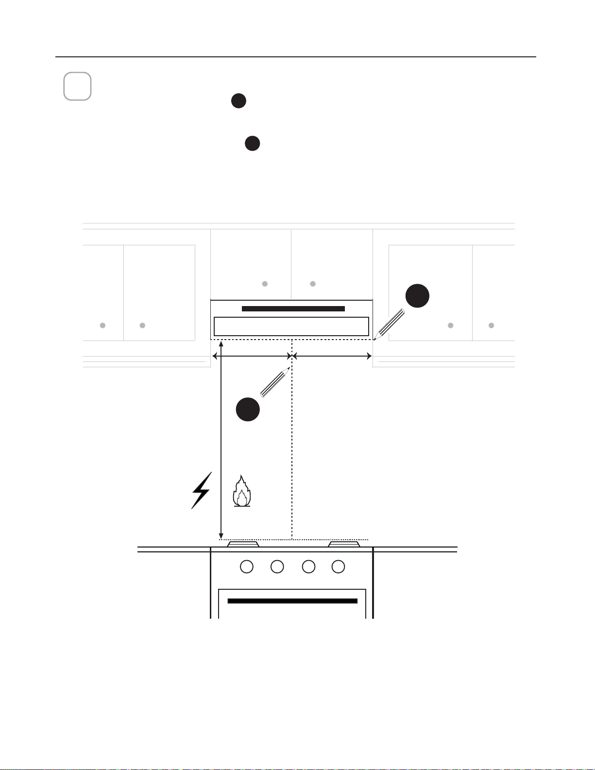
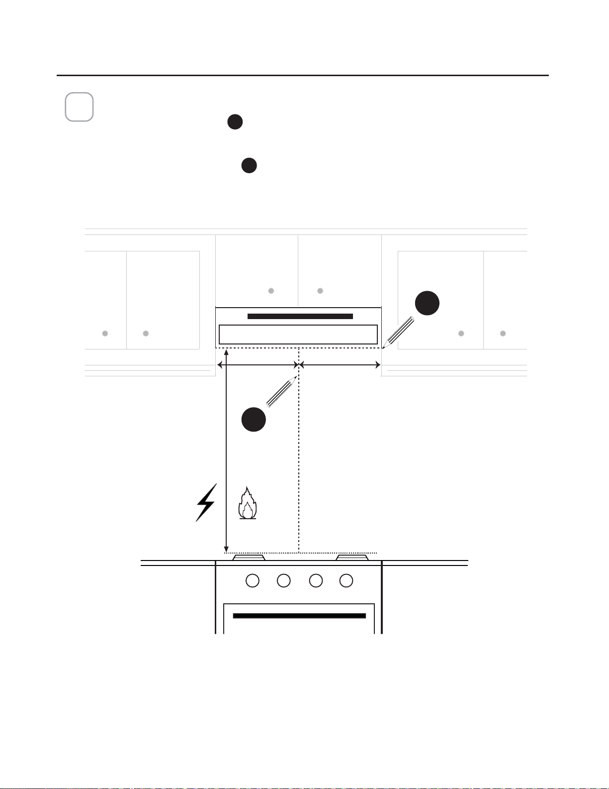
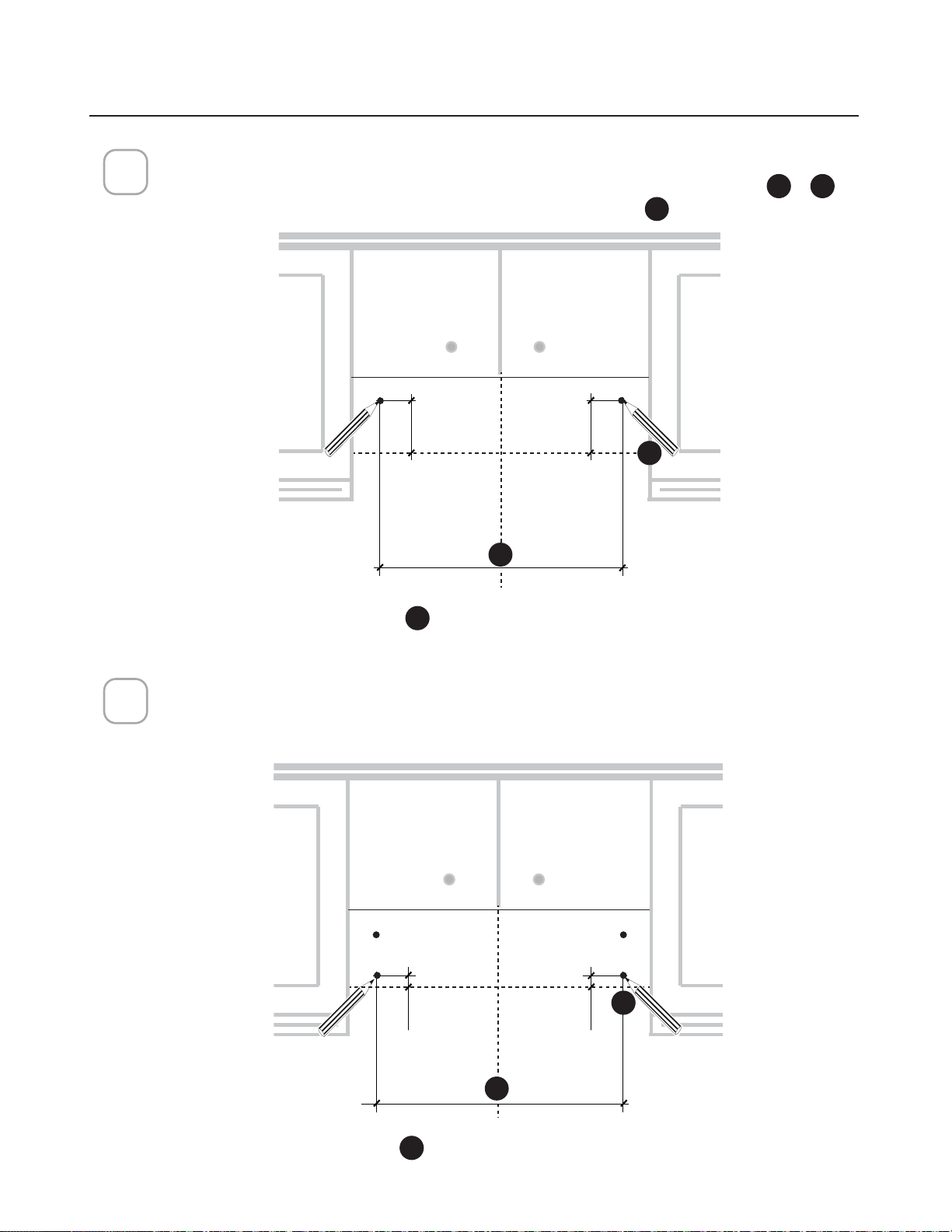
DRAW POSITIONING LINES
Draw a vertical line
H
from the supporting back wall to the ceiling or upper limit, at
the center of the area in which the hood will be installed.
Draw a horizontal line
I
from where the bottom edge of hood will be located, to
a minimum of 24" above an electric cooking surface and 30" above a gas cooking
surface.
1
MIN. 24" OVER ELECTRIC/MIN. 30" OVER GAS
I
H
MOUNTING RANGE HOOD ON WALL
==
Min. 24" Min.30"
22
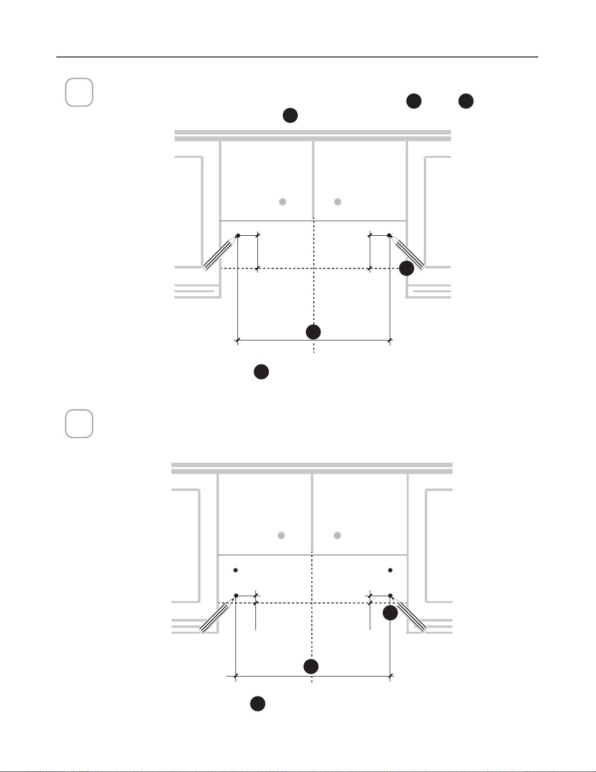
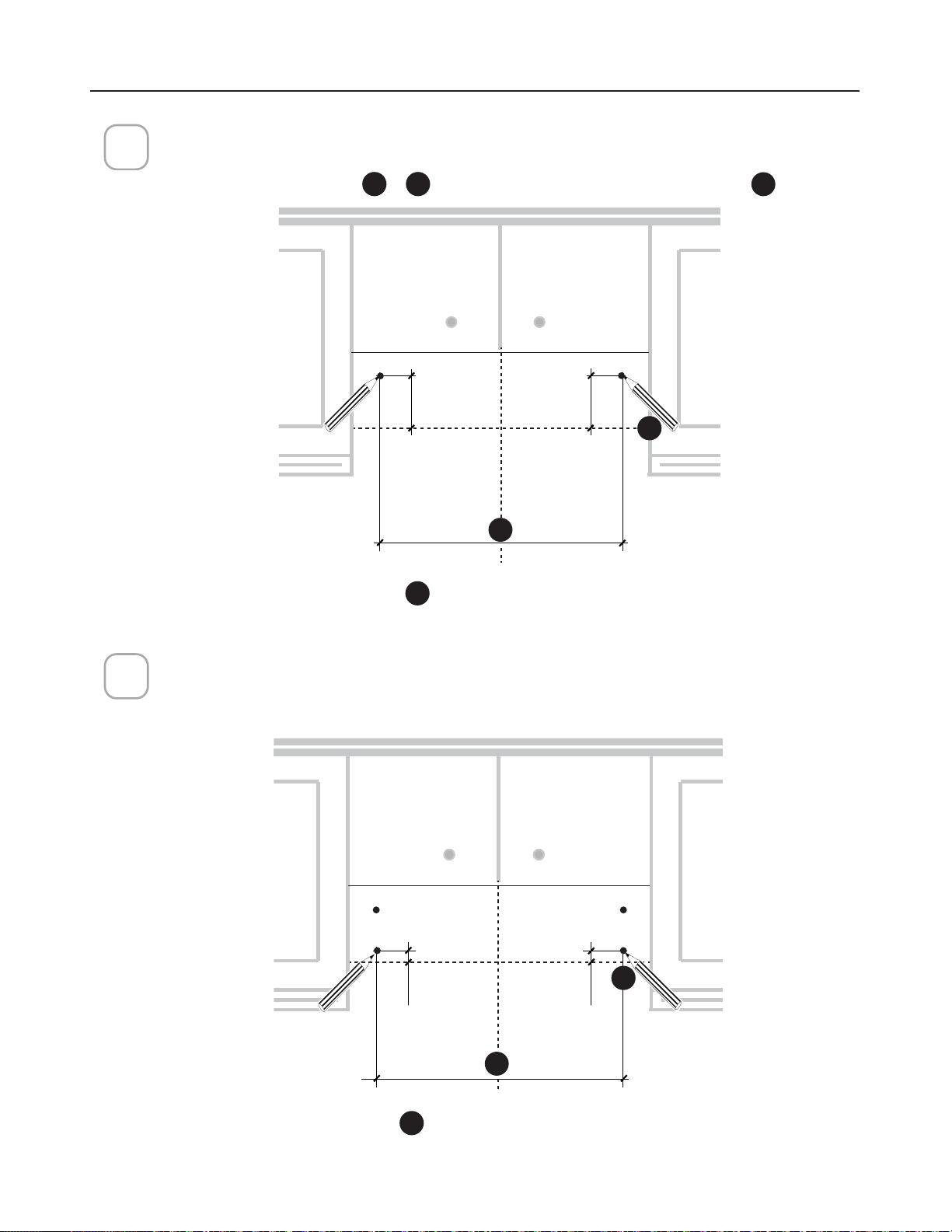
Mark the wall for the upper anchors.
0DUNWKHZDOOZKHUHLQGLFDWHGDERYHWKHKRUL]RQWDO
I
line at
J
distance on
the left and right of the vertical line
H
.
3
1”
1”
24” -->A=213/8”
A
4 15/16”
4 15/16”
A
Mark the wall for lower anchors.
Mark 1” below the Step 2. Upper Anchors. Take care to keep level.
30" = 27
30" = 27
3/8
3/8
"
36" = 33
36" = 33
3/8
3/8
"
30" = 27
30" = 27
3/8
3/8
"
36" = 33
36" = 33
3/8
3/8
"
MOUNTING RANGE HOOD ON WALL
2
I
J
H
I
J
H
23
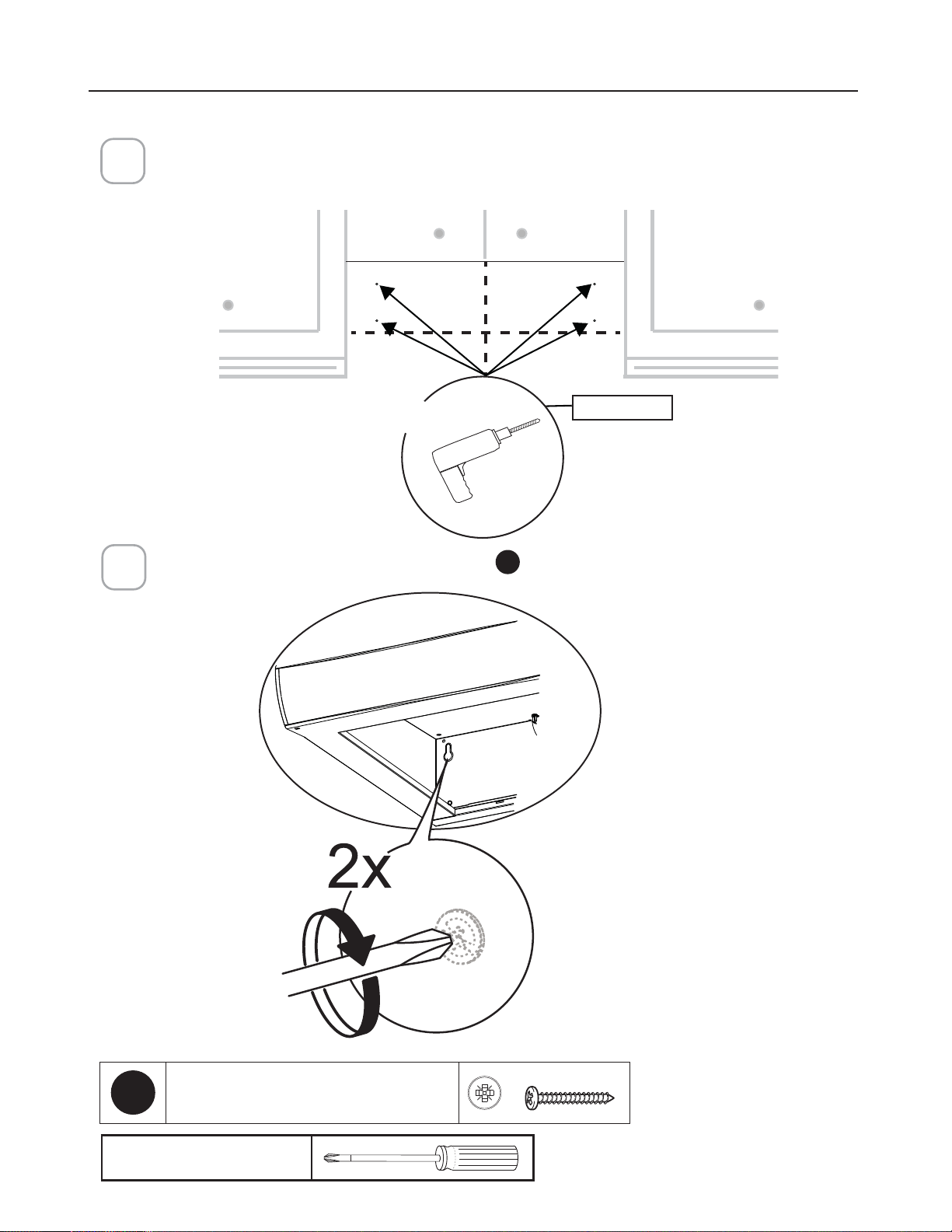
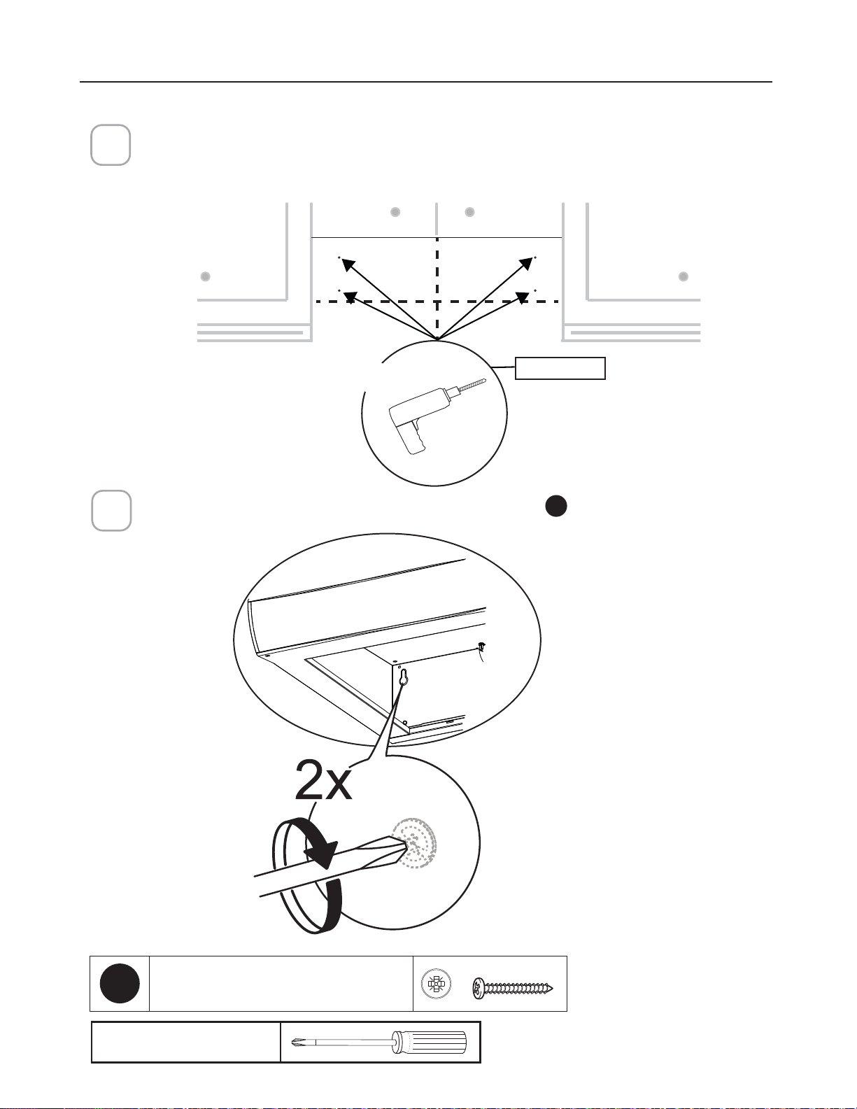
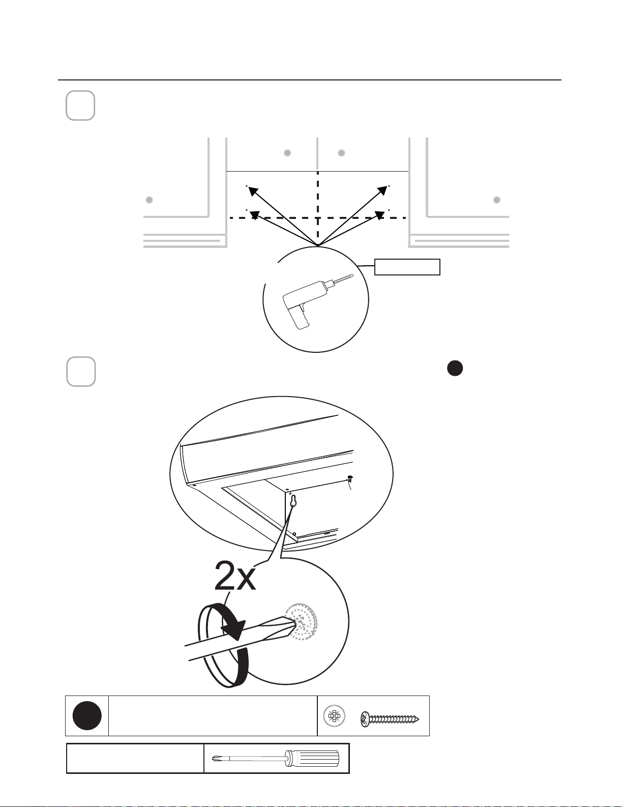
'ULOODWKKROHGLUHFWO\LQWRWKHZDOODWWKHFHQWHUSRLQWVPDUNHGLQVWHS
If fastener locations do not align with the studs, insert the purchased wall plugs in the holes.
In upper holes use two of the supplied screws
E
to secure the hood body to the wall.
´
;
5
Pozi Screwdriver
MOUNTING RANGE HOOD ON WALL
4
E
3R]L6FUHZV[
24
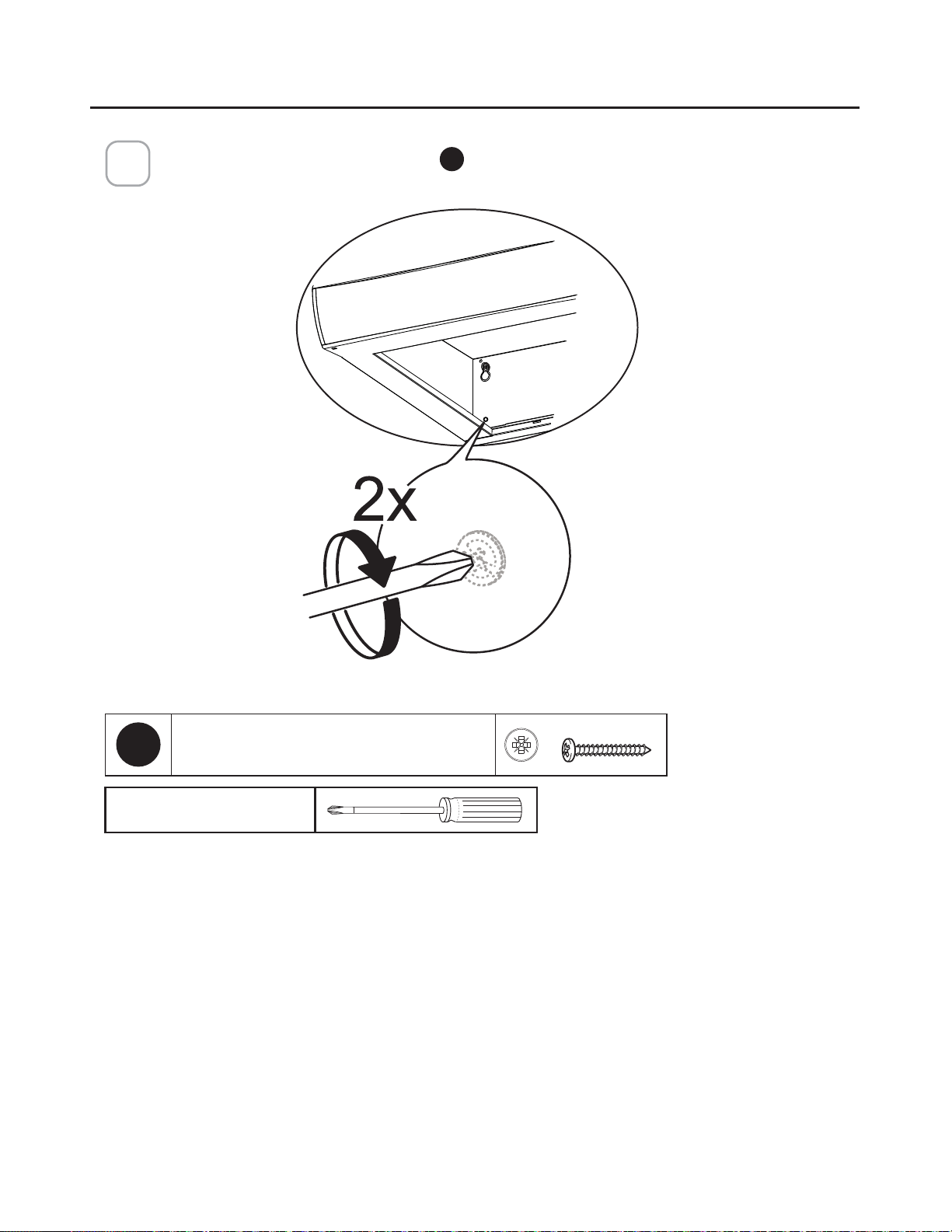
Using two remaining screws
E
anchor the hood in lower holes as indicated.
6
MOUNTING RANGE HOOD ON WALL
Pozi Screwdriver
E
3R]L6FUHZV[
CAUTION! For installations that have a recessed bottom, 1”X 2” x 12” (approximate length)
ZRRGVWULSVZLOOQHHGWREHSXUFKDVHGDQG´WWHGWRSURYLGHDOHYHOPRXQWLQJDUHD7KH&
:DOO0RXQW6FUHZVPD\ZRUNDVIDVWHQHUVLIQRWWKHQµDWKHDGZRRGVFUHZVZRXOGQHHGWR
be purchased and used for this type of installation
25
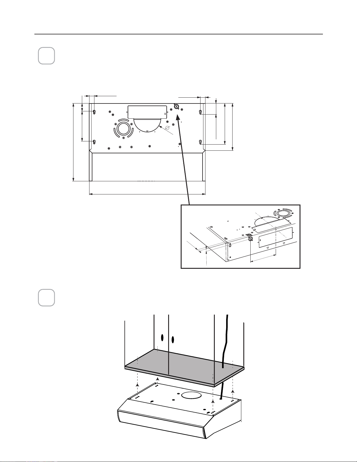
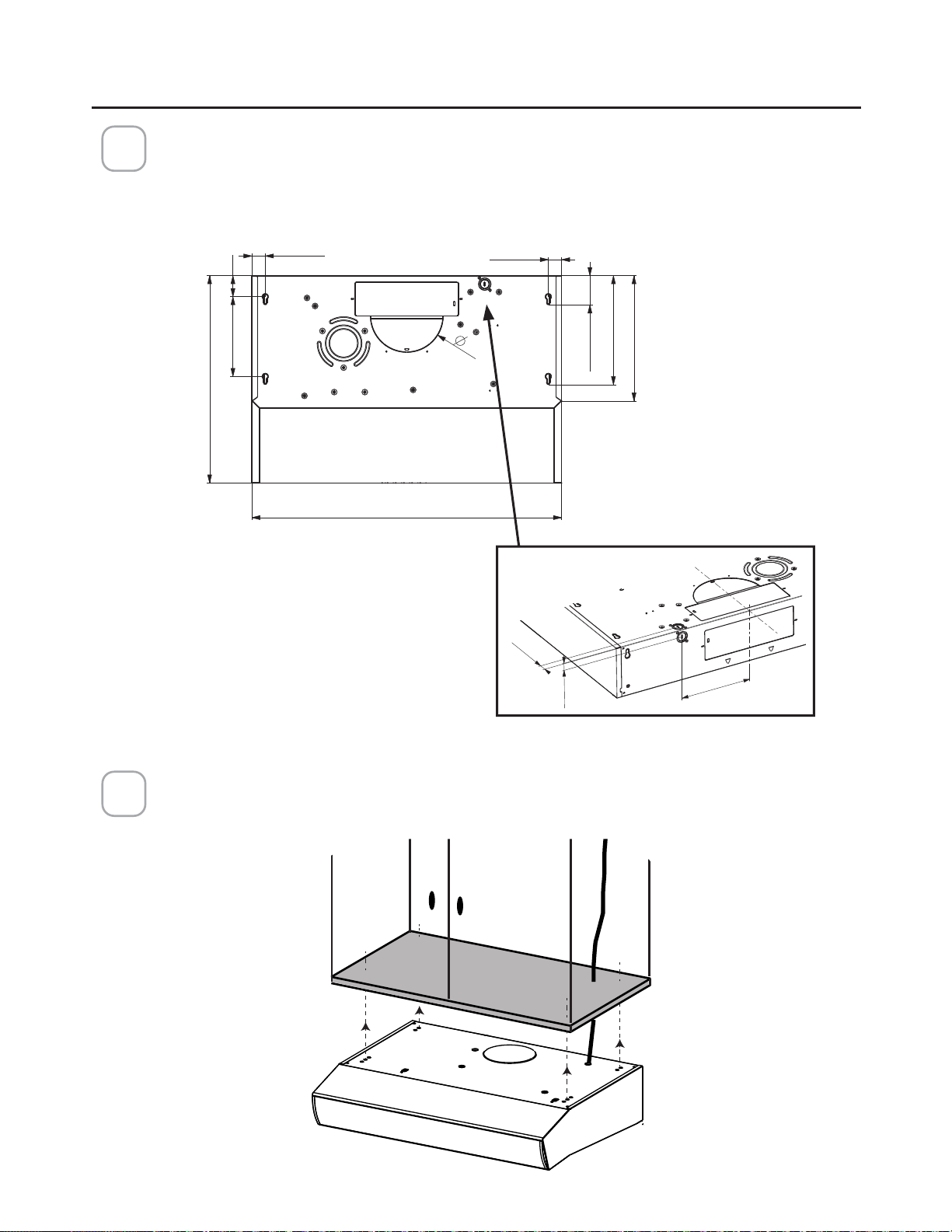
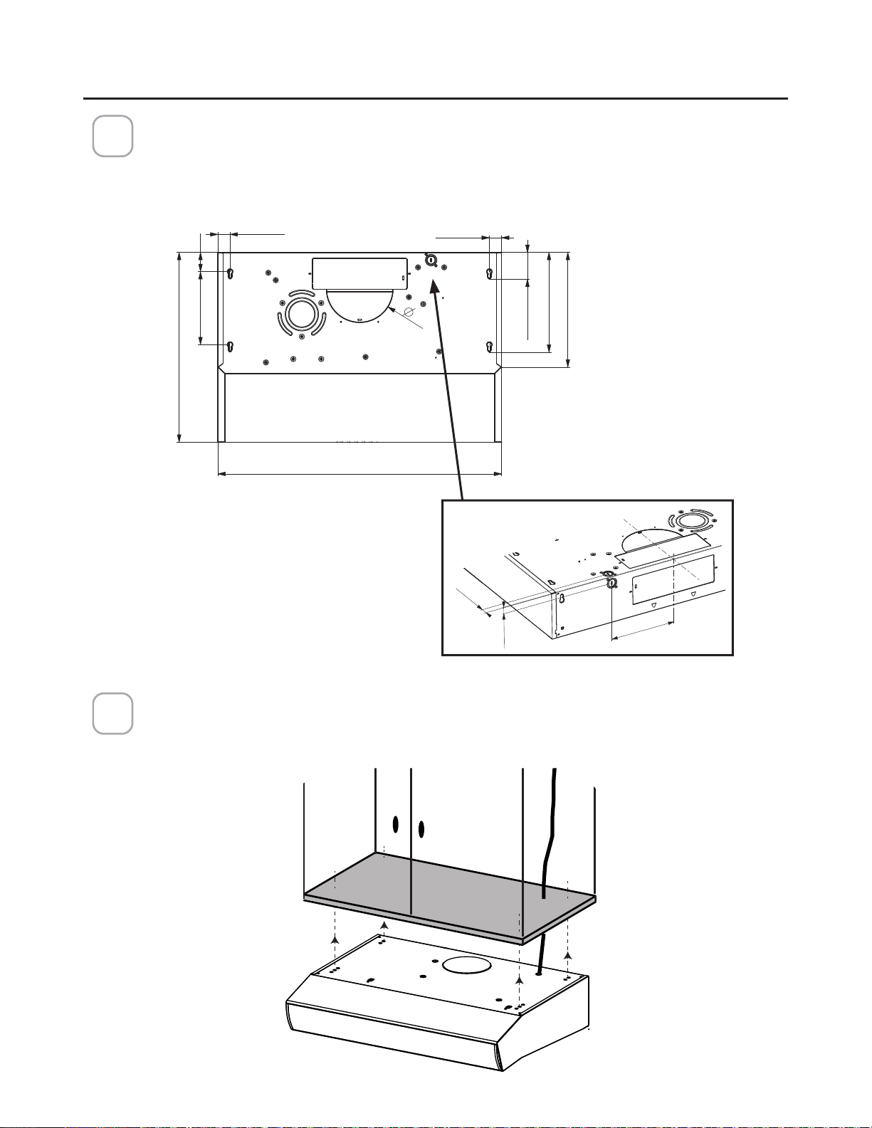
MOUNTING RANGE HOOD UNDER THE CABINET
20"
24"-30"-36"
12"
7"
2" 13/16
10" 1/2
1" 5/16
1" 5/16
7" 11/16 2"
7" 1/2
13/16"
13/16"
Locate the hole on the Range Hood for the power cord (See Section " CHOOSE
VERTICAL OR HORIZONTAL ELECTRICAL CONNECTION KNOCKOUT'S ") and pass
the cord through the appropriate hole.
Lift the hood to the cabinet and pass the power cord through the appropriate holes
on the Range Hood and through the cabinet to the power source.
1
2
Top View
BackView
26
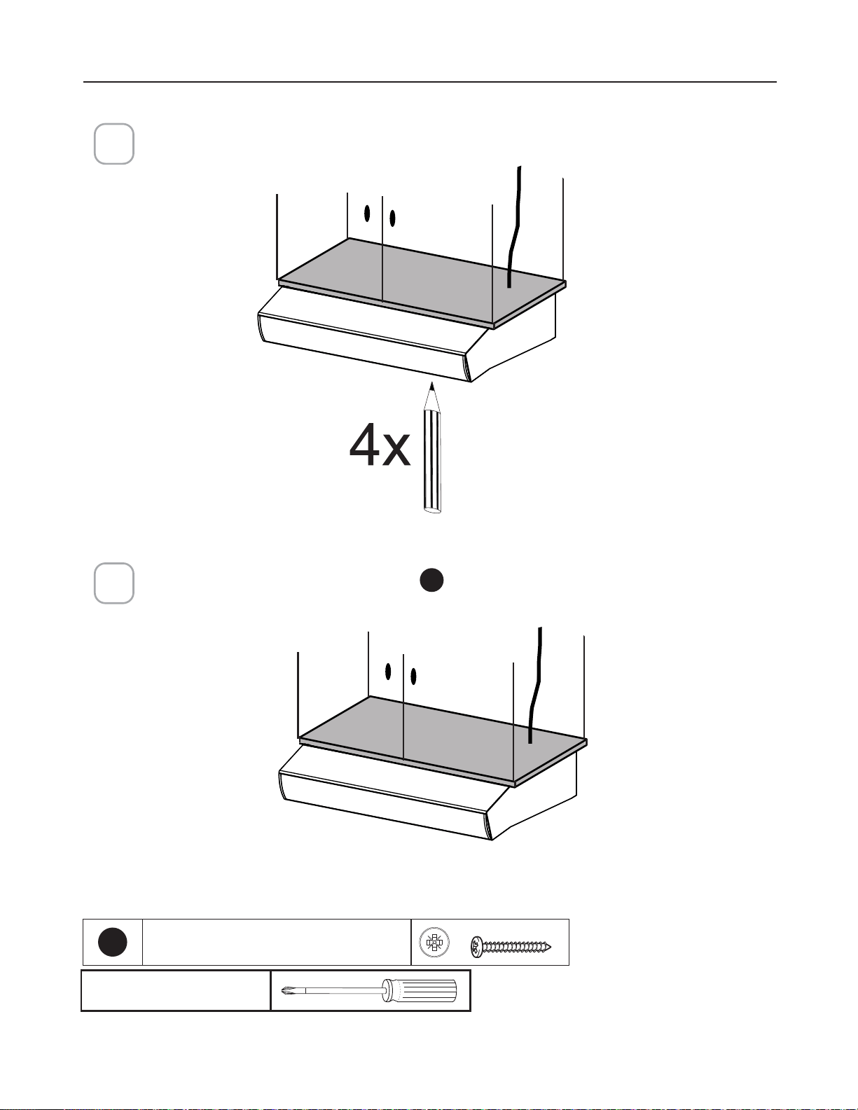
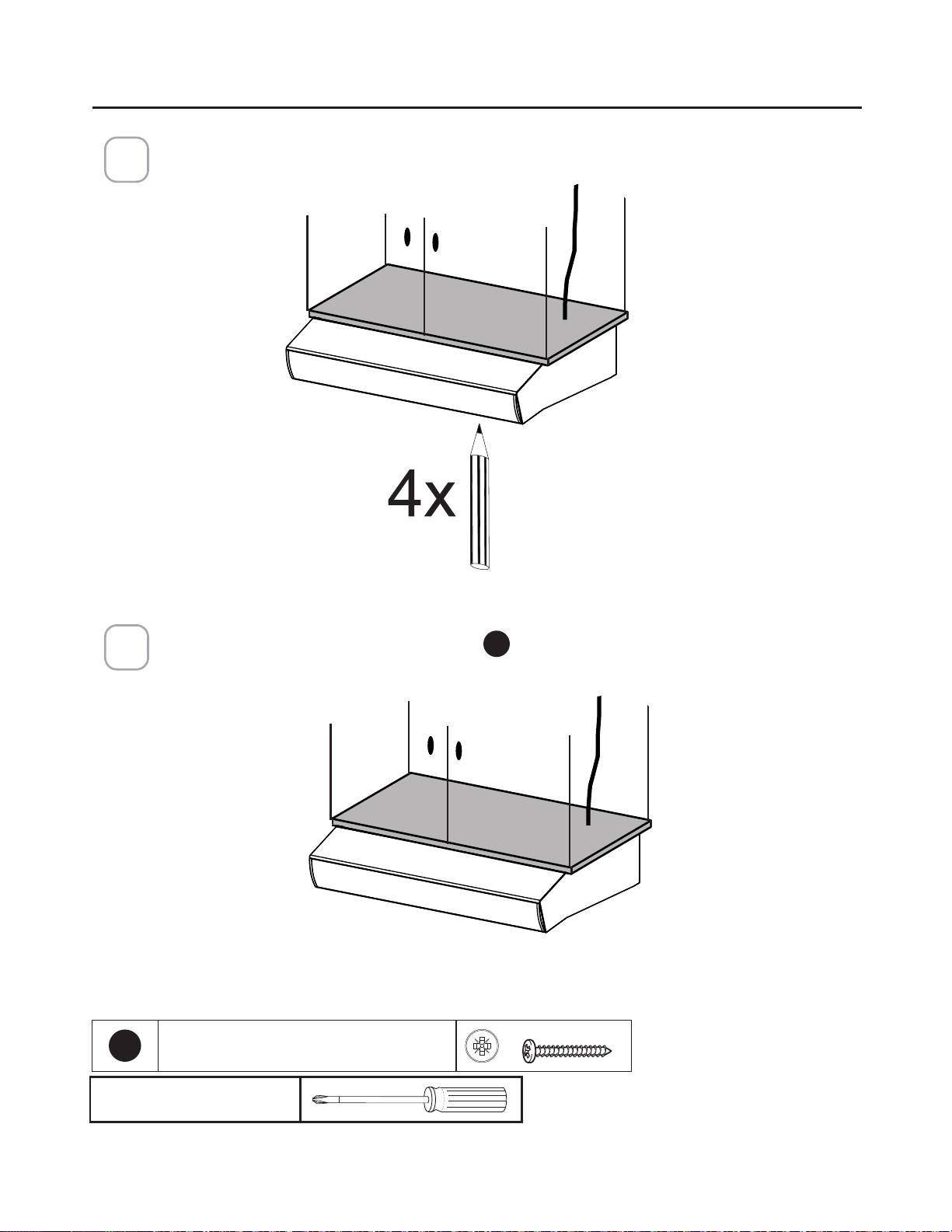
Mark the holes for attaching the hood to the cabinet. Verify the measurement with
the diagram on the previous page.
3
Attach the Hood body with 4 screws
E
from the bottom available with the hood.
4
E
3R]L6FUHZV[
Pozi Screwdriver
MOUNTING RANGE HOOD UNDER THE CABINET

27
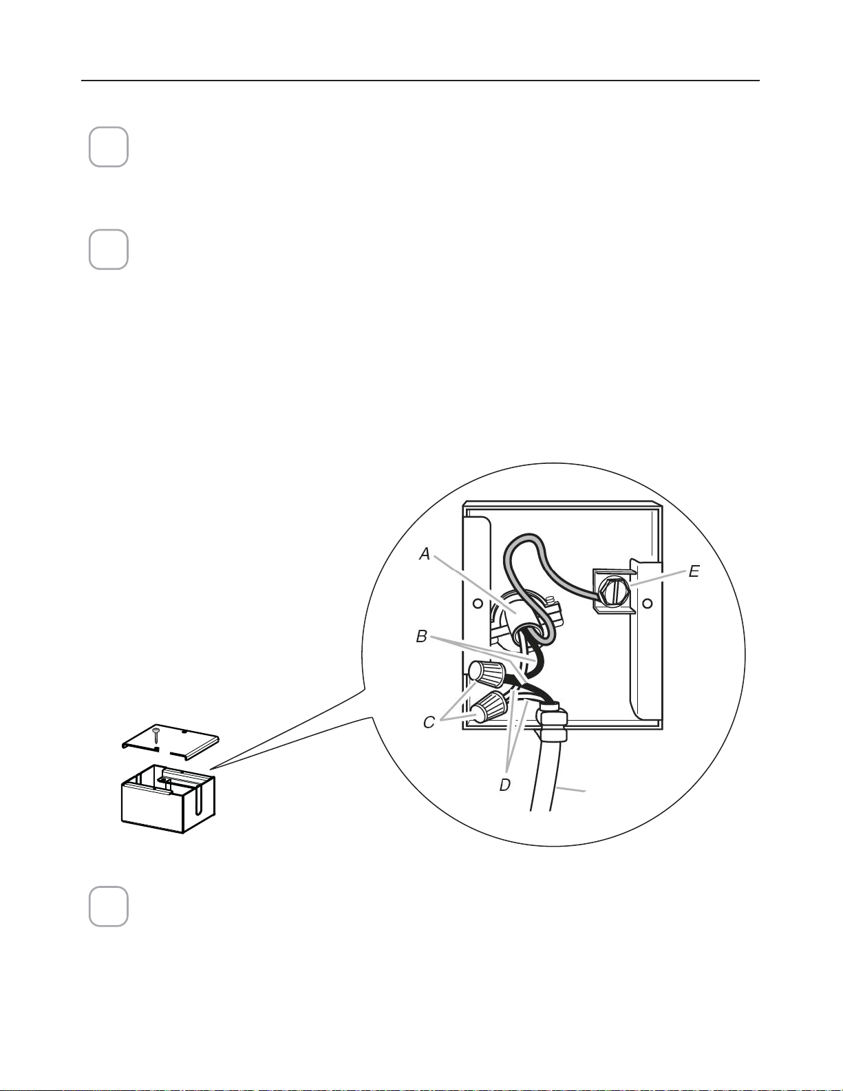
CONNECTING ELECTRICITY
Connecting the House Power.
Caution! Do not turn on the house power until the installation is complete.
• Feed the Power Supply Cable through the electrical knock out.
Wiring Box Connections.
• Attach the White lead of the Power Supply (A) to the White lead of the Range
Hood (D) with a twist-on type connector.
• Attach the Black lead of the Power Supply to the Black lead of the Range Hood
(B) with a twist-on type wire connector (C).
• Connect the Green (E) (Green and Yellow) ground wire under the grounding
screw.
1
3
2
Hood
wiring
5HSODFHWKH´HOGZLULQJFRPSDUWPHQWFRYHUDQGWKHJUHDVH´OWHUV
28
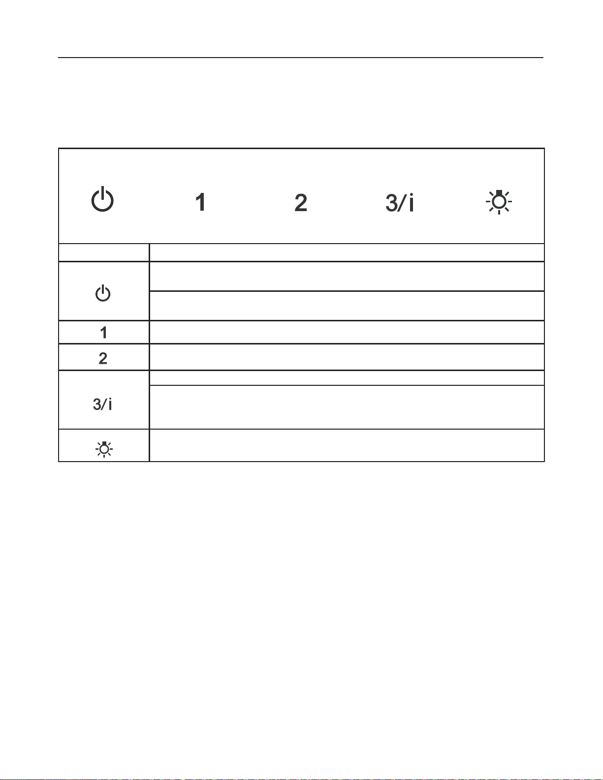
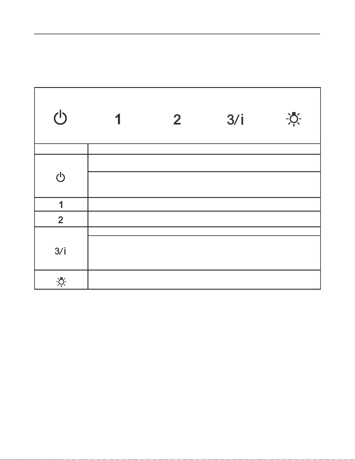
OPERATING THE CONTROLS
FOR BEST RESULTS
6WDUWWKH5DQJH+RRGVHYHUDOPLQXWHVEHIRUHFRRNLQJWRGHYHORSSURSHUDLUµRZ$OORZWKH
Range Hood to operate for several minutes after cooking is complete to clear all smoke and
odors from the kitchen.
Button Function
Fan Off Button:Turn the blower Off. The fan can be operated by pressing any of
the fan setting buttons.
Hold down this button for 2 seconds to activate delayed off function which will
keep the fan On for 15 minutes and automatically shut Off.
Fan Settings Buttons: Low Speed.
Fan Settings Buttons: Medium Speed.
Fan Settings Buttons: High Speed.
Hold down the button for 2 seconds to activate the INTENSIVE SPEED, which is
timed to run for 10 minutes. At the end of this time it will automatically return to
the speed set before.Suitable to deal with maximum levels of cooking fumes.
/LJKW%XWWRQ2Q2IIVZLWFKIRUWKH/('OLJKWV3UHVVWKH/,*+7EXWWRQWRWXUQWKH
light on and again to turn off.
29
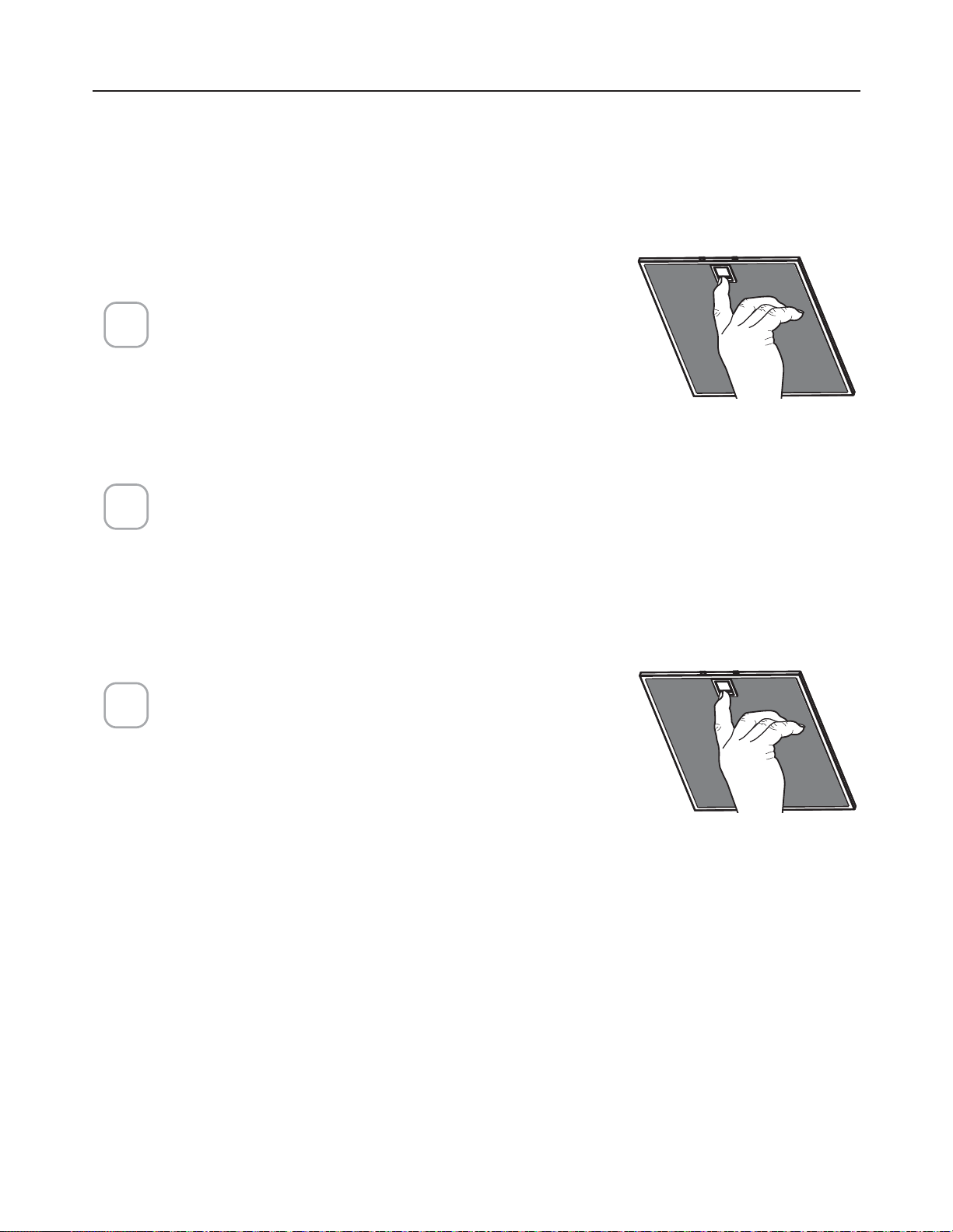
CARING FOR FILTERS
5HPRYHWKH´OWHUE\SXOOLQJWKHODWFKIRU-
ward and pulling down at the same time.
:DVKWKH´OWHUZLWKRXWEHQGLQJLW/HDYH
it to dry thoroughly before reinstalling. If
WKHVXUIDFHRIWKH´OWHUFKDQJHVFRORURYHU
WLPHHI´FLHQF\ZLOOQRWEHDIIHFWHG
7RUHLQVWDOOWKH´OWHUSXVKWKH´OWHUXSLQWR
position while pulling the latch forward,
then release the latch to lock into place
1
2
3
CLEANING METAL GREASE FILTERS
7KHPHWDOJUHDVH´OWDHUVFDQEHFOHDQHGLQKRWGHWHUJHQWVROXWLRQRUZDVKHG
in the dishwasher.
They should be cleaned every 2 months use, or more frequently if use is
particularly heavy.
NOTES:
&OHDQLQJLQDGLVKZDVKHUPD\GXOOWKH´QLVKRIWKHPHWDOJUHDVH´OWHUV
(QVXUHWKDWWKH´OWHUVDUHFRPSOHWHO\GU\EHIRUHLQVWDOOLQJWKHPEDFNLQWR
the Range Hood.
CLEANING EXTERIOR SURFACES
3OHDVHQRWHDEUDVLYHVDQGVFRXULQJDJHQWVFDQVFUDWFKUDQJHKRRG´QLVKHV
DQGVKRXOGQRWEHXVHGWRFOHDQ´QLVKHGVXUIDFHV
6WDLQOHVV6WHHO´QLVKFOHDQLQJLQVWUXFWLRQV
Clean exterior surfaces with a commercially available stainless steel cleaner.
30
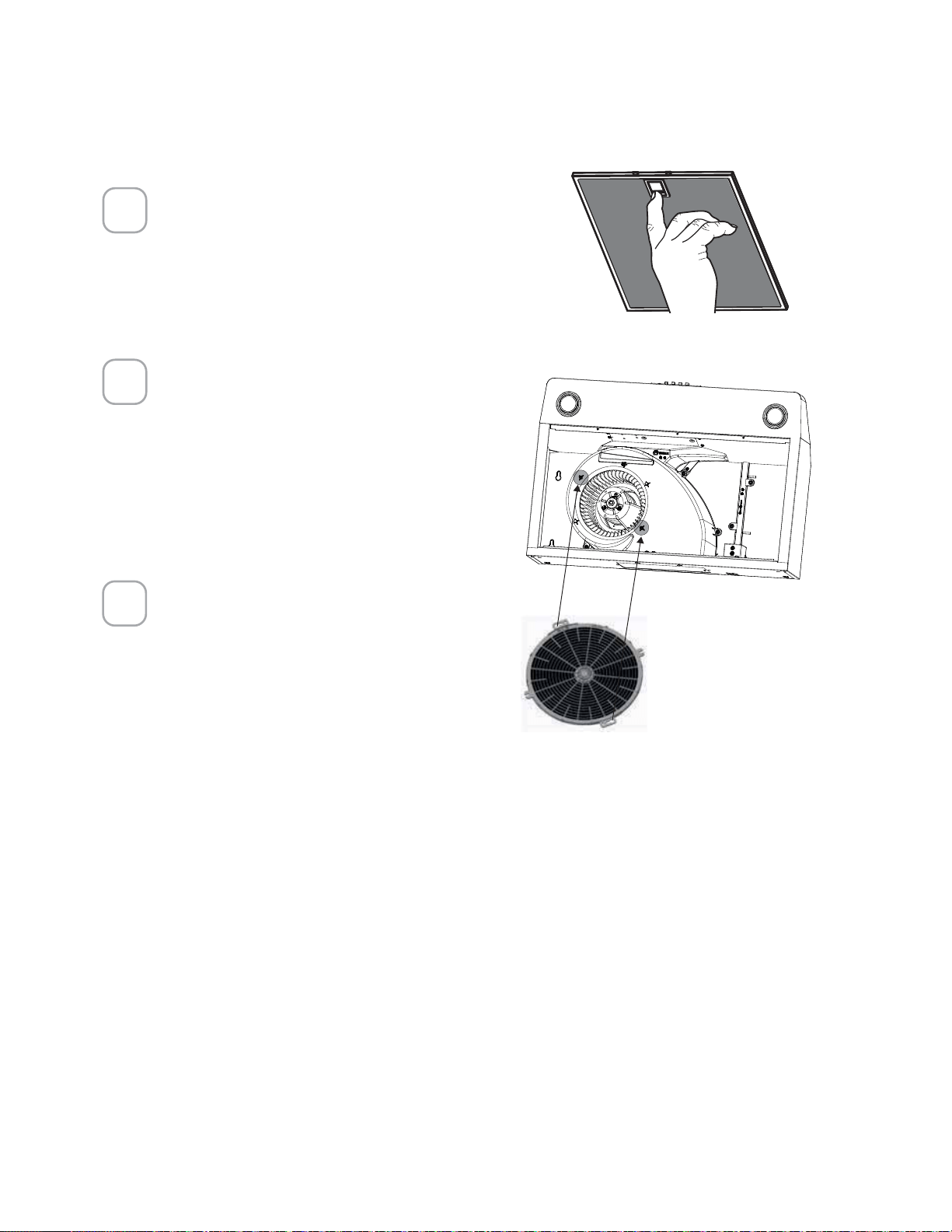
REPLACING ACTIVATED CHARCOAL FILTER
The Activated Charcoal Filters are not washable and cannot be regenerated,
and must be replaced approximately every 4 months of operation, or more
frequently with heavy usage.
5HPRYHWKHJUHDVH´OWHUV
Remove the old carbon
´OWHUE\UHPRYLQJWKHWZR
screws and then install the
QHZ´OWHUXVLQJWKHVDPH
two screw holes.
5HLQVWDOOWKHJUHDVH´OWHUV
1
2
3

31
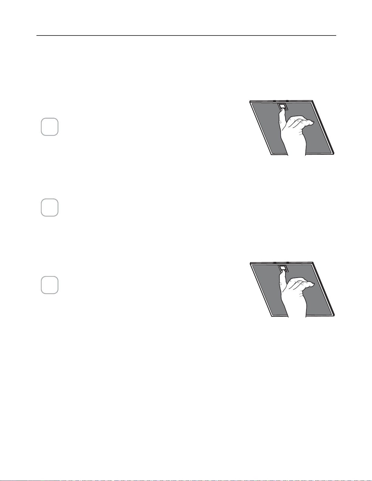
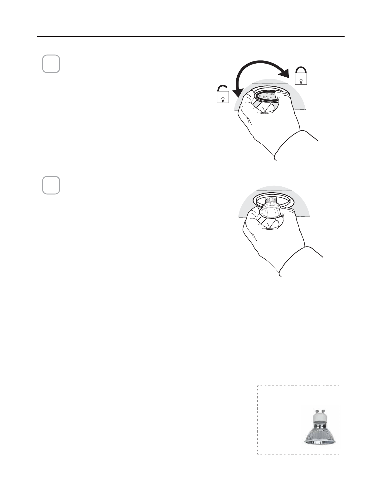
REPLACING LIGHTING
1
5 W LED Type GU10 lamp
Remove the bulb (See the picture).
Replace the bulb with a new one of
the same type, making sure that you
insert the two pins properly into the
housings on the lamp holder and
twist to lock back in place.
Attention: The bulbs could be hot,
please wait some minutes before the
replacing.
2
Gu10 self-ballasted led
lamps – listed in accor-
dance with ul
QP[M
DQFH
csa c22.2 No.
1993
32
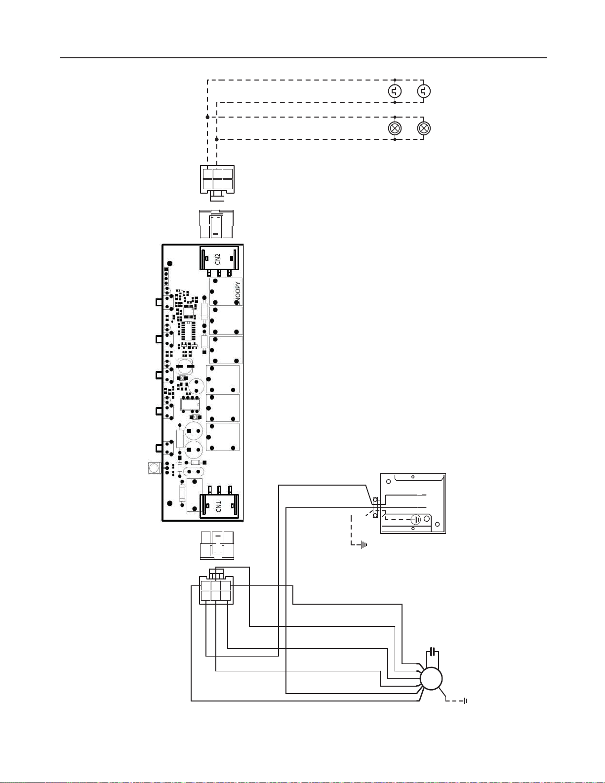
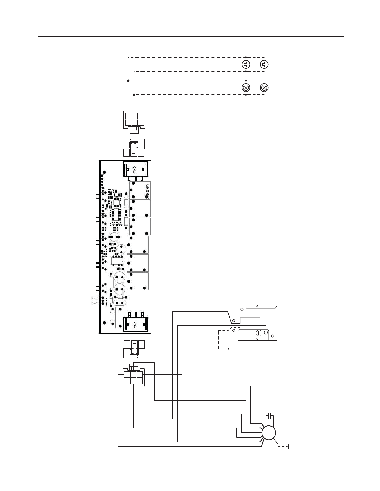
WIRING DIAGRAM
3&%
#-6
#38
.7
.0503
#-6
8)5(3:
03(
3&%
#38#-,
8)5(3:
#-6
03(
#-,7-5
8*3*/(
#09
:(
3&%8)5
-*/&
7BD)[
#38#-,
03(3&%
)"-0(&/
-".147
03(7-5
03(3&%
-&%
-".147
03(7-5

33
WARRANTY
January 4, 2016
FABER CONSUMER WARRANTY & SERVICE
All Faber products are warranted against any defect in materials or workmanship for the original purchaser
for a period of 1 year from the date of original purchase (requires proof of purchase). This warranty covers
labor and replacement parts. Faber, at its option, may repair or replace the product or components
necessary to restore the product to good working condition. To obtain warranty service, contact the dealer
from whom you purchased the range hood, or the local Faber distributor. If you cannot identify a local Faber
distributor, contact us at (508) 358-5353 for the name of a distributor in your area.
The following is not covered by Faber's warranty:
1. Service calls to correct the installation of your range hood, to instruct you how to use your range hood, to
replace or repair house fuses or to correct house wiring or plumbing.
2. Service calls to repair or replace range hood light bulbs, fuses or filters. Those consumable parts are
excluded from warranty coverage.
3. Repairs when your range hood is used for other than normal, single-family household use.
4. Damage resulting from accident, alteration, misuse, abuse, fire, flood, acts of God, improper installation,
installation not in accordance with electrical or plumbing codes or Faber documentation, or use of products
not approved by Faber.
5. Replacement parts or repair labor costs for units operated outside the United States or Canada, including
any non-UL or C-UL approved Faber range hoods.
6. Repairs to the hood resulting from unauthorized modifications made to the range hood.
7. Expenses for travel and transportation for product service in remote locations and pickup and delivery
charges. Faber range hoods should be serviced in the home.
THIS WARRANTY DOES NOT ALLOW RECOVERY OF INCIDENTAL OR CONSEQUENTIAL DAMAGES, INCLUDING, WITHOUT
LIMITATION, DIRECT, INDIRECT, INCIDENTAL, SPECIAL OR CONSEQUENTIAL DAMAGES, PERSONAL INJURY/WRONGFUL
DEATH OR LOST PROFITS FABER WARRANTY IS LIMITED TO THE ABOVE CONDITIONS AND TO THE WARRANTY PERIOD
SPECIFIED HEREIN AND IS EXCLUSIVE. EXCEPT AS EXPRESSLY SPECIFIED IN THIS AGREEMENT, FABER DISCLAIMS ALL
EXPRESS OR IMPLIED CONDITIONS, REPRESENTATIONS, AND WARRANTIES INCLUDING, WITHOUT LIMITATION, ANY
IMPLIED WARRANTIES OF MERCHANTABILITY OR FITNESS FOR A PARTICULAR PURPOSE
.
This warranty gives you specific legal rights that may vary from state to state.
Model#: ______________________________ Serial #: _____________________________

34
TABLE DES MATIÈRES
Section Page
Importantes consignes de sécurité 35
Dimensions de la hotte 39
Hauteur requise pour l’installation 40
Pièces 41
Outils nécessaires 42
Avant l’installation, retirez les matériaux d’expédition 43
Uniquement pour le marché canadien 44
&KRLVLVVH]GHVHQWUpHVGpIRQoDEOHVGH¢UDFFRUGHPHQWpOHFWULTXH
verticales ou horizontales 45
Options de méthode d’évacuation – avec ou sans conduit 47
Option de recirculation sans conduit 48
6RUWLHURQGHDYHFFRQGXLWGH¢SRXFHV 49
&RQGXLWVPpWDOOLTXHVUHFWDQJXODLUHVGH¢[¢SRVXUOHGHVVXV 51
&RQGXLWVPpWDOOLTXHVUHFWDQJXODLUHVGH¢[¢SRjODUULqUH 52
Choix de la méthode de montage 53
Montage de la hotte sur un mur 54
Montage de la hotte sous un cabinet de cuisine 58
Branchements électriques 60
Utilisation des commandes 61
(QWUHWLHQGHV´OWUHV 62
Remplacement des lampes 64
Schéma de câblage 65
Garantie 66

35
IMPORTANTES CONSIGNES DE SÉCURITÉ
VEUILLEZ LIRE ET CONSERVER LA PRÉSENTE NOTICE AVANT DE
COMMENCER L'INSTALLATION DE LA HOTTE DE CUISINE
AVERTISSEMENT: - POUR RÉDUIRE LE RISQUE D'UN FEU DE GRAISSE SUR LA TABLE
DE CUISSON:
D1HODLVVH]MDPDLVVDQVVXUYHLOODQFHOHVpOpPHQWVGHODVXUIDFHGHFXLVVRQjWHPSpUDWXUH
élevée. Les bouillonnements excessifs peuvent provoquer de la fumée et les débordements
GHJUDLVVHSHXYHQWVHQµDPPHU/KXLOHGRLWrWUHFKDXIIpHOHQWHPHQWjXQHWHPSpUDWXUH
basse ou moyenne.
E$VVXUH]YRXVGHWRXMRXUVPHWWUHHQPDUFKHODKRWWHORUVTXHYRXVFXLVLQH]jWHPSpUDWXUH
pOHYpHRXSUpSDUH]XQPHWVµDPEpSH[FUrSHV6X]HWWHFHULVHVMXELOpE§XIµDPEp
c) Nettoyez régulièrement les ventilateurs d'aspiration. Assurez-vous de ne pas laisser de
ODJUDLVVHVDFFXPXOHUVXUOHYHQWLODWHXURXOH´OWUH
G8WLOLVH]WRXMRXUVGHVSRrOHVHWFDVVHUROHVGHODWDLOOHDSSURSULpH8WLOLVH]WRXMRXUVGHV
XVWHQVLOHVGHFXLVLQHGHODWDLOOHDGDSWpHjFHOOHGHOpOpPHQWFKDXIIDQW
AVERTISSEMENT: - POUR PRÉVENIR LES BLESSURES EN CAS DE FEU DE GRAISSE SUR
LA TABLE DE CUISSON, SUIVEZ LES RECOMMANDATIONS SUIVANTES*:
De728))(=/(6)/$00(6jODLGHGXQFRXYHUFOHKHUPpWLTXHGXQHSODTXHjELVFXLWVRX
d'un plateau métallique, puis éteignez le brûleur. FAITES ATTENTION AUX BRÛLURES.
Si le feu ne s'éteint pas immédiatement, QUITTEZ LES LIEUX ET APPELEZ LES POMPIERS.
b) NE PRENEZ JAMAIS UNE CASSEROLE EN FLAMME - Vous pourriez vous brûler.
F187,/,6(=-$0$,6'(/($8QLXQOLQJHjYDLVVHOOHRXXQWRUFKRQPRXLOOpSRXUpWHLQGUH
le feu. Cela pourrait provoquer une violente explosion de vapeur.
d) Utilisez un extincteur UNIQUEMENT si:
9RXVrWHVFHUWDLQTXLOVDJLWGXQH[WLQFWHXUGHFODVVH$%&HWTXHYRXVFRQQDLVVH]
bien son mode d'emploi.
/HIHXHVWGHIDLEOHLQWHQVLWpHWVHOLPLWHjOHQGURLWRLODGpPDUUp
/HVSRPSLHUVRQWGpMjpWpDSSHOpV
8QHYRLHGHVRUWLHVHWURXYHGHUULqUHYRXVSHQGDQWTXHYRXVpWHLJQH]OHVµDPPHV
*
D'après le guide «Kitchen Firesafety Tips» publié par la NFPA aux États-Unis
AVERTISSEMENT - POUR RÉDUIRE LE RISQUE D'INCENDIE OU DE CHOC ÉLECTRIQUE,
QXWLOLVH]MDPDLVFHYHQWLODWHXUHQDVVRFLDWLRQDYHFXQGLVSRVLWLIGHUpJODJHGHYLWHVVHj
semi-conducteurs.
AVERTISSEMENT - POUR RÉDUIRE LES RISQUES D'INCENDIE, DE CHOC ÉLECTRIQUE OU
DE BLESSURE CORPORELLE, RESPECTEZ LES INSTRUCTIONS SUIVANTES:
1. Utilisez cet appareil uniquement de la façon prévue par le fabricant. Pour toute question,
communiquez avec le fabricant.
2. $YDQWGHSURFpGHUjOHQWUHWLHQRXDXQHWWR\DJHGHODSSDUHLOFRXSH]ODOLPHQWDWLRQDX
niveau du panneau électrique et verrouillez-le pour vous assurer que l'électricité n'est pas
rétablie accidentellement. S'il n'est pas possible de verrouiller le dispositif d'interruption
GHODOLPHQWDWLRQDI´FKH]GHIDoRQIHUPHHWELHQYLVLEOHXQDYLVGHGDQJHUSDUH[HPSOH
jODLGHGXQHpWLTXHWWHVXUOHSDQQHDX
$77(17,21¢'HVWLQpjXQXVDJHGHYHQWLODWLRQJpQpUDOHXQLTXHPHQW1XWLOLVH]SDVFH
dispositif pour l'aspiration de vapeurs ou de matériaux dangereux ou explosifs.
AVERTISSEMENT - POUR RÉDUIRE LES RISQUES D'INCENDIE, DE CHOC ÉLECTRIQUE OU
'(%/(6685(&25325(//(5(63(&7(=/(6,16758&7,21668,9$17(6¢
1. /LQVWDOODWLRQHWOHEUDQFKHPHQWpOHFWULTXHGRLYHQWrWUHUpDOLVpVSDUXQWHFKQLFLHQTXDOL´p

36
TOUTE OUVERTURE DANS LE MUR OU LE PLANCHER À PROXIMITÉ DE LA HOTTE
DOIT ÊTRE SCELLÉE.
Un espace libre d'au moins 24" est requis entre le bas de la hotte et la surface de cuisson ou
le comptoir. Cette hotte a été homologuée par l'UL à cette distance de la surface de cuisson.
L’espace libre minimal requis peut-être plus grand, selon la réglementation en matière de
construction de votre région. Pour les cuisinières à gaz et les cuisinières combinées, un espace
minimal de 30" est recommandé et pourrait être exigé.
Les armoires suspendues de chaque côté de l'appareil doivent se trouver à au moins 18" de la
surface de cuisson ou du comptoir. Consultez la notice d'installation de la surface de cuisson
ou de la cuisinière fournie par le fabricant avant de pratiquer des ouvertures.
INSTALLATION DANS UNE MAISON MOBILE L'installation de cette hotte doit être conforme
à la Partie 3280 de la norme Manufactured Home Construction and Safety Standards, Title 24
CFR (précédemment la partie 280 de la norme Federal Standard for Mobile Home Construction
DQG6DIHW\7LWOH+8'&RQVXOWH]OD´FKHWHFKQLTXHpOHFWULTXH
CRITÈRES DE VENTILATION
Déterminez quelle méthode de ventilation est mieux adaptée à votre application. Les conduits
peuvent passer par le mur ou le toit.
3RXUJDUDQWLUXQHPHLOOHXUHHI´FDFLWpODORQJXHXUGHVFRQGXLWVHWOHQRPEUHGHFRXGHVGRLYHQW
être le plus limités que possible. Le diamètre des conduits devrait être uniforme. N'installez pas
GHX[FRXGHVHQVHPEOH8WLOLVH]XQUXEDQSRXUFDQDOLVDWLRQVD´QGHVFHOOHUWRXVOHVMRLQWVGX
système de conduits. Utilisez un calfeutrage pour sceller les ouvertures dans le mur extérieur
ou le plancher, autour du clapet.
,OQHVWSDVUHFRPPDQGpGXWLOLVHUGHVFRQGXLWVµH[LEOHV/HVFRQGXLWVµH[LEOHVSURYRTXHQW
XQHFRQWUHSUHVVLRQHWGHODWXUEXOHQFHTXLGLPLQXHQWJUDQGHPHQWOHI´FDFLWpGHODSSDUHLO
$VVXUH]YRXV TXH OHVSDFH OLEUH GDQV OH PXU RX OH SODQFKHU HVW VXI´VDQW SRXU OH FRQGXLW
d'évacuation avant de pratiquer les ouvertures. Ne coupez jamais une poutre ou un chevron,
sauf si c'est absolument nécessaire. S'il s'avère nécessaire de couper une poutre ou un chevron,
la construction d'un renforcement est requise.
AVERTISSEMENT - Pour réduire le risque d'incendie, utilisez uniquement des conduits
métalliques.
ATTENTION - Pour réduire le risque d'incendie et pour évacuer adéquatement l'air, assurez-
YRXVGHUDFFRUGHUOHVFRQGXLWVjOH[WpULHXU¨1HGLIIXVH]SDVODLUGpYDFXDWLRQGDQVGHV
HVSDFHVjOLQWpULHXUGHVPXUVRXGXSODIRQGRXHQFRUHjOLQWpULHXUGXQJUHQLHUGXQH
galerie technique ou d'un garage.
HWFRQIRUPpPHQWjWRXVOHVFRGHVHWQRUPHVHQYLJXHXULQFOXDQWFHX[FRQFHUQDQWOD
FRQVWUXFWLRQjOpSUHXYHGXIHX
2. $´QGHJDUDQWLUXQHFRPEXVWLRQHWXQHpYDFXDWLRQDGpTXDWHVGHVJD]SDUOHVFRQGXLWHV
GHODFKHPLQpHGHVDSSDUHLOVjFRPEXVWLRQXQHERQQHDpUDWLRQHVWQpFHVVDLUHSRXU
éviter le refoulement. Respectez les lignes directrices fournies par le fabricant du matériel
chauffant, ainsi que les normes de sécurité comme celles publiées par la National Fire
3URWHFWLRQ$VVRFLDWLRQ1)3$HWOD$PHULFDQ6RFLHW\IRU+HDWLQJ5HIULJHUDWLRQDQG
$LU&RQGLWLRQLQJ(QJLQHHUV$6+5$(DX[eWDWV8QLVDLQVLTXHOHVFRGHVHQYLJXHXU
dans votre région.
3. /RUVTXHYRXVIDLWHVXQHRXYHUWXUHRXSHUFH]GDQVXQPXURXOHSODIRQGYHLOOH]jQH
SDVHQGRPPDJHUOHV´OVpOHFWULTXHVRXGDXWUHVGLVSRVLWLIVFDFKpV
4. /HVYHQWLODWHXUVFDQDOLVpVGRLYHQWWRXMRXUVrWUHUDFFRUGpVjOH[WpULHXU
37
FICHE TECHNIQUE ÉLECTRIQUE
Une alimentation de courant alternatif de 120 volts à 60 Hz est requise sur un circuit à fusible
distinct de 15 ampères. Il est recommandé d'installer un fusible temporisé ou un disjoncteur.
Le fusible doit être calibré conformément aux codes en vigueur pour les caractéristiques
nominales électriques de l'appareil, indiquées sur la plaque signalétique située à l'intérieur
de l'appareil, à proximité du compartiment des câblages externes.
INSTALLATION ÉLECTRIQUE AVEC BOÎTIER DE CONNEXION
CET APPAREIL DOIT ÊTRE UNIQUEMENT BRANCHÉ À L'AIDE DE FILS DE CUIVRE. Le
FDOLEUHGHV´OVGRLWrWUHFRQIRUPHDX[FULWqUHVGHODGHUQLqUHpGLWLRQGX1DWLRQDO(OHFWULFDO
&RGHGHO$16,1)3$HWGHOHQVHPEOHGHVFRGHVHWUpJOHPHQWDWLRQVHQYLJXHXU/H
FDOLEUHGHV´OVHWOHVFRQQH[LRQVGRLYHQWrWUHDGDSWpVDX[FDUDFWpULVWLTXHVQRPLQDOHVGH
l'appareil. Il est possible de se procurer un exemplaire des normes indiquées ci-dessus en
communiquant avec:
National Fire Protection Association
Batterymarch Park
Quincy, Massachusetts 02269 (États-Unis)
Cet appareil devrait être branché directement au sectionneur à fusible (ou au disjoncteur)
SDUXQFkEOHµH[LEOHGHFXLYUHDYHFEOLQGDJHRXJDLQHQRQPpWDOOLTXH/DLVVH]XQ
peu de jeu dans le câble pour permettre le déplacement de l'appareil si des travaux
GHQWUHWLHQVDYpUDLHQWQpFHVVDLUHV8QUDFFRUGGHFRQGXLWKRPRORJXpSDUO8/GH
doit être installé aux deux extrémités du câble d'alimentation (au niveau de l'appareil
et de la boîte de liaison).
/RUVGHODUpDOLVDWLRQGXEUDQFKHPHQWpOHFWULTXHUpDOLVH]XQWURXGHGDQVOHPXU
S'il s'agit d'un trou dans le bois, il doit être poncé pour le rendre lisse. S'il s'agit d'un
WURXGDQVOHPpWDOXQSDVVH´OVHVWUHTXLV
• Le système de ventilation DOIT déboucher à l'extérieur.
• NE FAITES PAS déboucher les conduits dans un grenier ou un autre endroit
fermé.
• N’UTILISEZ PAS un clapet de sécheuse mural de 4".
,OQHVWSDVUHFRPPDQGpGXWLOLVHUGHVFRQGXLWVµH[LEOHV
• N’ENTRAVEZ PASOHµX[GHODLUGHFRPEXVWLRQHWGHYHQWLODWLRQ
• Le non-respect des exigences en matière de ventilation pourrait entraîner un
incendie.
AVERTISSEMENT
!
Installation dans les climats froids
Le système de ventilation doit prévoir un registre antirefoulement supplémentaire pour réduire le
µX[GDLUIURLGLQYHUVHDLQVLTXXQHEDUULqUHWKHUPLTXHQRQPpWDOOLTXHSRXUUpGXLUHODFRQGXFWLRQGHV
températures extérieures. Le registre doit être installé du côté air froid par rapport à la barrière thermique.
La barrière thermique doit être positionnée le plus près que possible de l'endroit où le système de
ventilation pénètre dans la partie chauffée de la maison.

38
• Une mise à la terre électrique est requise pour cette hotte.
• N'UTILISEZ PAS un tuyau d'eau froide pour la mise à la terre si celui-ci est
branché par des joints en plastique, par des rondelles non métalliques ou
d'autres matériaux.
• N'UTILISEZ PAS une conduite de gaz pour la mise à la terre.
• N'INSTALLEZ PAS un fusible sur le circuit neutre ou le circuit de mise à la
terre. La présence d'un fusible dans le circuit neutre ou de mise à la terre
peut entraîner un choc électrique.
&RQVXOWH]XQpOHFWULFLHQTXDOL´pVLYRXVQrWHVSDVFHUWDLQGHODPLVHjODWHUUH
de la hotte.
/HQRQUHVSHFWGHVH[LJHQFHVGHOD´FKHWHFKQLTXHpOHFWULTXHSRXUUDLW
entraîner un incendie.
AVERTISSEMENT
!
39
DIMENSIONS DE LA HOTTE
3
29 15/16” - 35 15/16”
30" 36"
30"
36"

40
Min.24” Min.30”
HAUTEUR REQUISE POUR L’INSTALLATION
MIN. 24" AU-DESSUS D’UNE
SURFACE ÉLECTRIQUE
/ MIN. 30" AU-DESSUS D’UNE
SURFACE AU GAZ
41
A
B
C
D
Accessoires disponibles
Filtre à charbon actif (FILTER5)
Remarque¢OH´OWUHjFKDUERQHVW´[pjODLGHGHGHX[
YLVYRLUSDJH¢HW´JXUH¢&
/HV´OWUHVjFKDUERQGRLYHQWrWUHDFKHWpVDXSUqVGH
revendeurs Faber agréés.
7pOpFRPPDQGHVDQV´OREMCTRL2
PIÈCES
RÉF. PIÈCE
A
&RUSVGHODKRWWH&RPSUHQGOHVFRPPDQGHVOpFODLUDJHOHV´OWUHVOH
ventilateur
1
B
Amortisseur ([¢SR)1
C
%ULGHURQGHGH¢SR 1
D
Grille (uniquement pour le marché canadien) 1
RÉF.
PIÈCE
E
9LV3R]L[¢¢SR
4
F
9LV7RU[[¢SR
4
PIÈCES INCLUSES

42
PIÈCES NÉCESSAIRES
3,¿&(6VXLWH
PIÈCE
&RQGXLWVPpWDOOLTXHVURQGVGH¢SR
&RQGXLWVPpWDOOLTXHVUHFWDQJXODLUHVGH¢[¢SR
$PRUWLVVHXUGH¢SR
&RQQHFWHXUVGH´O
Cordon d’alimentation électrique.
-
&KHYLOOHVSRXUFORLVRQVVqFKHVRXDXWUHV´[DWLRQVPX-
rales adaptées à votre installation.
&DSXFKRQPXUDO¢FDSXFKRQGHWRLW'RLWrWUHDFKHWp
séparément
OUTILS NÉCESSAIRES
OUTIL
Ruban à mesurer
Crayon
3HUFHXVHpOHFWULTXHDYHFIRUHWGH¢SR
Tournevis à pointe Phillips
Tournevis Torx
Tournevis Pozi

43
AVANT L’INSTALLATION, RETIREZ LES
MATÉRIAUX D’EXPÉDITION
Retirez l’emballage latéral.
Retirez l’emballage en mousse et la barre en bois.
1
2
3
Prêt pour l’installation.
Attention¢QH
soulevez pas la
hotte à l’aide de la
barre en bois
44
D
UNIQUEMENT POUR LE MARCHÉ CANADIEN
1
2
3RXUOHVLQVWDOODWLRQVDYHFFRQGXLWVXQLTXHPHQW¢
5HWLUH]OHV´OWUHVXQSDUXQHQOHVSRXVVDQWYHUVODUULqUHGHODKRWWHHWHQOHVWLUDQW
en même temps vers le bas.
Installez les vis comme illustré.
Installez la grille
D
DYHFOHVGHX[YLVUHWLUpHVjOpWDSH¢9LVVH]ODJULOOHGH
protection à l’emplacement indiqué sur l’illustration ci-dessous. (L’emplacement
correct comporte une découpe rectangulaire pour s’adapter à la grille.)
Veillez à bien visser la grille pour éviter tout bruit indésirable.
Retirez les vis comme illustré.
Retirez deux des vis du carter de l’ensemble moteur, comme illustré.
3
Tournevis à pointe Phillips

45
5HWLUH]OHV´OWUHVXQSDU
un en les poussant vers
l’arrière de la hotte et en
les tirant en même temps
vers le bas.
Retirez le couvercle du
boîtier de câblage en
GpYLVVDQWOHV¢YLV
Préparation de la hotte pour les entrées défonçables
CHOISISSEZ DES ENTRÉES DÉFONÇABLES
'(¢5$&&25'(0(17e/(&75,48(9(57,&$/(6
OU HORIZONTALES
1
2
Tournevis à pointe Phillips
7" 1/2
13/16"
13/16"
=
46
7URXDUULqUHKRUL]RQWDO
Choisissez le trou arrière pour le raccordement électrique et cassez l’entrée défonçable
avec un tournevis ou un autre outil.
Lors de l’installation, faites passer le câble d’alimentation dans ce trou.
3
7URXVXSpULHXUYHUWLFDO
Choisissez le trou du dessus pour le raccordement électrique et cassez l’entrée
défonçable avec un tournevis ou un autre outil.
Lors de l’installation, faites passer le câble d’alimentation dans ce trou.
4
47
OPTIONS DE MÉTHODE D’ÉVACUATION – AVEC
OU SANS CONDUIT
Option avec conduit AVEC
6257,(521'('(¢328&(6¢
– verticale
– horizontale
¢SR
Arrière
Dessus
¢SR
3 1/4¢SR
¢SR
3 1/4¢SR
Arrière
Dessus
5HQGH]YRXVjODSDJH5HQGH]YRXVjODSDJH
5HQGH]YRXVjODSDJH
&21'8,760e7$//,48(65(&7$1*8/$,5(6'(¢;¢32
– verticale
– horizontale
OPTION DE RECIRCULATION SANS
CONDUIT
Exige
l’achat
d’un
accessoire
à charbon
actif
48
b1
a
b2
Retirez le couvercle du ventilateur
indiqué (ne jetez pas la vis).
Avant de faire fonctionner la hotte,
UHPHWWH] OHV ´OWUHVj JUDLVVH H[LVWDQWV
DSUqVDYRLULQVWDOOpOH´OWUHjFKDUERQDFWLI
Remettez en place le couvercle du
YHQWLODWHXUPRGL´pDYHFODPrPHYLV
Coupez le
couvercle
à l’endroit
indiqué sur
OLPDJH¢E
-HWH]
recyclez
les pièces
supérieures
du
couvercle du
ventilateur.
d
b3
OPTION DE RECIRCULATION SANS CONDUIT
5HQGH]YRXVjODSDJH¢
$FFHVVRLUHGH´OWUHjFKDUERQ
actif requis – (FILTER5) acheté
séparément.
c
3RXUOHVLQVWDOODWLRQVVDQVFRQGXLWXQLTXHPHQW¢
1. Retirez les deux vis situées sur le carter du
moteur à l’emplacement indiqué.
3ODFH]OH´OWUHjFKDUERQDYHFOHVODQJXHWWHV
contre le boîtier du ventilateur, à l’emplacement
LQGLTXpVXUOD´JXUH¢
c
. Le trou de montage
en poire de la face avant du FILTER5 doit se
WURXYHUVXUODVXUIDFHVXSpULHXUHGX´OWUH8QH
couche de charbon de bois sera visible à travers
les grilles.
3. Utilisez les deux vis retirées précédemment
SRXU´[HUOH),/7(5HQSODFH
REMARQUE¢3RXUOHVLQVWDOODWLRQVVDQVFRQGXLW
la grille pour le Canada ne doit PAS être utilisée.
49
6257,(521'($9(&&21'8,7'(¢328&(6
Coupez à l’endroit indiqué.
Retirez les zones rectangulaire et semi-circulaire avec des cisailles métalliques.
Arrière
Dessus
¢SR
5HTXLV¢DPRUWLVVHXU
URQGGH¢SRXFHV
à acheter
séparément.
1
Attention : si un
coude est nécessaire,
installez-le aussi loin que
possible de l’ouverture
d’évacuation de la hotte.
50
5HQGH]YRXVjODSDJH¢
Installez la bride avec les vis de transition de bride
F
.
5HTXLV¢DPRUWLVVHXUURQGGH¢SRXFHVjDFKHWHUVpSDUpPHQW)L[HUODPRUWLVVHXUj
l’aide de ruban adhésif pour conduit en aluminium.
5DFFRUGH]OHFRQGXLWPpWDOOLTXHURQGGH¢SRXFHVDXFDSXFKRQPXUDO¢FDSXFKRQ
GHWRLWDFKHWpVpSDUpPHQWSXLV´[H]OHFRQGXLW
2
3
Tournevis Torx
5(0$548(¢: La bride doit être montée avec la lèvre tournée vers le haut.
Utilisez uniquement les vis fournies pour la bride
F
9LV7RU[[¢SR
4
51
Choisissez la sortie d’air supérieure rectangulaire ou la sortie d’air arrière rectangulaire
et coupez à l’endroit indiqué (voir la page 52 pour la sortie arrière)
Installez la sortie d’air rectangulaire incluse avec deux vis
F
.
5DFFRUGH]OHFRQGXLWPpWDOOLTXHDXFDSXFKRQPXUDO¢FDSXFKRQGHWRLWDFKHWp
VpSDUpPHQWSXLV´[H]OHFRQGXLW
Arrière
Dessus
Dessus
3
1/4
[¢SR
1
2
3
Tournevis Torx
F
9LV7RU[[¢SR
Attention : si un coude est
nécessaire, installez-le aussi
loin que possible de l’ouverture
d’évacuation de la hotte.
CONDUITS MÉTALLIQUES RECTANGULAIRES DE
¢;¢32685/('(6686
52
5HQGH]YRXVjODSDJH¢
Arrière
Arrière
3
1/4
[¢SR
Utilisez la sortie d’air arrière et coupez à l’endroit indiqué.
Installez la sortie d’air rectangulaire incluse avec deux vis
F
.
1
2
Tournevis Torx
F
9LV7RU[[¢SR
CONDUITS MÉTALLIQUES RECTANGULAIRES DE
¢;¢32£/$55,¿5(
Attention : si un coude est
nécessaire, installez-le aussi
loin que possible de l’ouverture
d’évacuation de la hotte.
5DFFRUGH]OHFRQGXLWPpWDOOLTXHDXFDSXFKRQPXUDO¢FDSXFKRQGHWRLWDFKHWp
VpSDUpPHQWSXLV´[H]OHFRQGXLW
3

53
CHOIX DE LA MÉTHODE DE MONTAGE
Installation pour montage mural
Installation pour montage sous cabinet
3DJH¢
3DJH¢
54
MONTAGE DE LA HOTTE SUR UN MUR
TRACEZ LES LIGNES DE PLACEMENT
Tracez une ligne verticale
H
entre le mur de soutien arrière et le plafond ou la limite
supérieure, au centre de la zone dans laquelle la hotte sera installée.
Tracez une ligne horizontale
I
à partir de l’emplacement du bord inférieur de la
KRWWHMXVTXjXQPLQLPXPGH¢SRXFHVDXGHVVXVGXQHVXUIDFHGHFXLVVRQpOHF-
WULTXHRXGH¢SRXFHVDXGHVVXVGXQHVXUIDFHGHFXLVVRQDXJD]
1
¢328&(60,1,080$8'(6686'81(685)$&(
'(&8,6621e/(&75,48(¢¢328&(60,1,080
AU-DESSUS D’UNE SURFACE DE CUISSON AU GAZ
I
H
MONTAGE DE LA HOTTE SUR UN MUR
==
¢SRXFHV
minimum
¢SRXFHV
minimum
55
1”
1”
24” -->A=213/8”
A
4 15/16”
4 15/16”
A
¢SR
¢SR
3/8
3/8
¢SR
¢SR
¢SR
¢SR
3/8
3/8
¢SR
¢SR
¢SR
¢SR
3/8
3/8
¢SR
¢SR
¢SR
¢SR
3/8
3/8
¢SR
¢SR
I
J
H
I
J
H
Marquez l’emplacement des ancrages supérieurs sur le mur.
0DUTXH]OHPXUjOHQGURLWLQGLTXpj¢FP¢¢SRXFHVDXGHVVXVGHODOLJQH
horizontale à la distance
I
à
J
gauche et à droite de la ligne verticale
H
.
3
Marquez l’emplacement des ancrages inférieurs sur le mur.
(IIHFWXH]XQHPDUTXHj¢FP¢SRVRXVOpWDSH¢$QFUDJHVVXSpULHXUV$VVXUH]
vous que les marques sont horizontales les unes par rapport aux autres.
MONTAGE DE LA HOTTE SUR UN MUR
2
56
3HUFH]XQWURXGH¢SRGLUHFWHPHQWGDQVOHPXUDX[SRLQWVFHQWUDX[PDUTXpVj
OpWDSH¢
6LOHVHPSODFHPHQWVGHV´[DWLRQVQHVRQWSDVDOLJQpVDYHFOHVPRQWDQWVLQVpUH]OHV
chevilles murales achetées dans les trous.
Dans les trous supérieurs, utilisez deux des vis fournies
E
SRXU´[HUOHFRUSVGHOD
hotte au mur.
´
;
5
Tournevis Pozi
MONTAGE DE LA HOTTE SUR UN MUR
4
E
9LV3R]L[¢¢SR

57
À l’aide de deux vis restantes
E
, ancrez la hotte dans les trous inférieurs, comme
indiqué.
6
MONTAGE DE LA HOTTE SUR UN MUR
Tournevis Pozi
E
9LV3R]L[¢¢SR
ATTENTION! Pour les installations qui ont un fond encastré, des bandes de bois de
¢[¢¢[¢¢SRXFHVORQJXHXUDSSUR[LPDWLYHGHYURQWrWUHDFKHWpHVHWLQVWDOOpHVSRXUIRXUQLU
une zone de montage de niveau. Les vis de montage mural 12C peuvent fonctionner comme
GHVDWWDFKHVGH´[DWLRQVLQRQ¢YLVjERLVjWrWHSODWHGRLYHQWrWUHDFKHWpHVHWXWLOLVpHVSRXU
ce type d’installation.
58
20"
24"-30"-36"
12"
7"
2" 13/16
10" 1/2
1" 5/16
1" 5/16
7" 11/16 2"
7" 1/2
13/16"
13/16"
MONTAGE DE LA HOTTE SOUS UN CABINET DE
CUISINE
Localisez le trou sur la hotte pour le cordon d’alimentation (voir la rubrique
¢&+2,6,66(=(175e(6'e)21d$%/(69(57,&$/(628+25,=217$/(6¢SXLV
faites passer le cordon dans le trou approprié.
Soulevez la hotte jusqu’à ce qu’elle entre en contact avec le cabinet, puis faites
passer le cordon d’alimentation à travers les trous appropriés de la hotte et du
cabinet, jusqu’à la source d’alimentation.
1
2
Vue de dessus
Vue arrière
59
0DUTXH]OHVWURXVSRXU´[HUODKRWWHDXFDELQHW9pUL´H]ODPHVXUHjODLGHGXVFKpPD
de la page précédente.
3
)L[H]OHFRUSVGHODKRWWHDYHFOHV¢YLV
E
du bas fournies avec la hotte.
4
E
9LV3R]L[¢¢SR
Tournevis Pozi
MONTAGE DE LA HOTTE SOUS UN CABINET DE
CUISINE
60
BRANCHEMENTS ÉLECTRIQUES
&RQQH[LRQjODOLPHQWDWLRQpOHFWULTXHGHODPDLVRQ
Attention! Laissez le courant de la maison coupée jusqu’à ce que l’installation soit
terminée.
• Faites passer le câble d’alimentation à travers l’entrée défonçable.
Connexions du boîtier de câblage.
• 5DFFRUGH]OH´OEODQFGXEORFGDOLPHQWDWLRQADX´OEODQFGHODKRWWHD) à
l’aide d’un connecteur de type à visser.
• 5DFFRUGH]OH´OQRLUGXEORFGDOLPHQWDWLRQADX´OQRLUGHODKRWWHD) à l’aide
d’un connecteur de type à visser.
• 5DFFRUGH]OH´OGHPDVVHYHUWE) (vert et jaune) sous la vis de mise à la masse.
1
3
2
Câblage
de la
hotte
Remettez en place le couvercle du compartiment de câblage sur
SODFHHWOHV´OWUHVjJUDLVVH
61
UTILISATION DES COMMANDES
POUR DE MEILLEURS RÉSULTATS
'pPDUUH]ODKRWWHSOXVLHXUVPLQXWHVDYDQWODFXLVVRQD´QGREWHQLUXQHERQQHFLUFXOD-
WLRQGDLU/DLVVH]ODKRWWHIRQFWLRQQHUSHQGDQWSOXVLHXUVPLQXWHVDSUqVOD´QGHODFXLVVRQ
D´Q¢GpOLPLQHUWRXWHIXPpHHWRGHXUGHFXLVLQH
Bouton Fonction
%RXWRQGDUUrWGXYHQWLODWHXU¢pWHLQWOHYHQWLODWHXU/HYHQWLODWHXUSHXWrWUHDF-
tionné en appuyant sur l’un quelconque des boutons de réglage du ventilateur.
0DLQWHQH]FHERXWRQHQIRQFpSHQGDQW¢VHFRQGHVSRXUDFWLYHUODIRQFWLRQGDUUrW
GLIIpUpTXLPDLQWLHQWOHYHQWLODWHXUHQPDUFKHSHQGDQW¢PLQXWHVSXLVVDUUrWH
automatiquement.
%RXWRQVGHUpJODJHGXYHQWLODWHXU¢EDVVHYLWHVVH
%RXWRQVGHUpJODJHGXYHQWLODWHXU¢YLWHVVHPR\HQQH
%RXWRQVGHUpJODJHGXYHQWLODWHXU¢JUDQGHYLWHVVH
0DLQWHQH]OHERXWRQHQIRQFpSHQGDQW¢VHFRQGHVSRXUDFWLYHUOD9,7(66(,17(1-
6,9(TXLHVWSURJUDPPpHSRXUIRQFWLRQQHUSHQGDQW¢PLQXWHV£OD´QGHFHWWH
période, le ventilateur reviendra automatiquement à la vitesse réglée auparavant.
Cette fonction est utile pour gérer les pics de fumées de cuisson.
%RXWRQGpFODLUDJHLQWHUUXSWHXUPDUFKHDUUrWSRXUOHVOXPLqUHV/('$SSX\H]VXU
le bouton LIGHT pour allumer la lumière et à nouveau pour l'éteindre.
62
ENTRETIEN DES FILTRES
5HWLUH]OH´OWUHHQWLUDQWOHORTXHWYHUV
l’avant et en le tirant en même temps vers
le bas.
/DYH]OH´OWUHVDQVOHSOLHU/DLVVH]OHVpFKHU
complètement avant de le réinstaller. Si la
VXUIDFHGX´OWUHFKDQJHGHFRXOHXUDX´OGX
WHPSVVRQHI´FDFLWpQHQVHUDSDVDIIHFWpH
3RXUUHPHWWUHOH´OWUHHQSODFHSRXVVH]OH
´OWUHHQSRVLWLRQYHUVOHKDXWWRXWHQWLUDQW
le loquet vers l’avant, puis relâchez le loquet
pour le verrouiller en place
1
2
3
1(772<$*('(6),/75(6£*5$,66((10e7$/
/HV´OWUHVjJUDLVVHHQPpWDOSHXYHQWrWUHQHWWR\pVGDQVXQHVROXWLRQGp-
tergente chaude ou lavés au lave-vaisselle.
,OVGRLYHQWrWUHQHWWR\pVWRXVOHV¢PRLVRXSOXVIUpTXHPPHQWVLOXWLOLVDWLRQ
de la hotte est particulièrement intense.
5(0$548(6¢
/HQHWWR\DJHDXODYHYDLVVHOOHSHXWWHUQLUOD´QLWLRQGHV´OWUHVjJUDLVVHHQ
métal.
$VVXUH]YRXVTXHOHV´OWUHVVRQWFRPSOqWHPHQWVHFVDYDQWGHOHVUH-
mettre en place dans la hotte.
NETTOYAGE DES SURFACES EXTERNES
Veuillez noter que les abrasifs et les agents à récurer peuvent rayer les sur-
IDFHVGH´QLWLRQGHODKRWWHHWQHGRLYHQWGRQFSDVrWUHXWLOLVpV
,QVWUXFWLRQVGHQHWWR\DJHSRXUOHVVXUIDFHVGH´QLWLRQHQDFLHULQR[\GDEOH¢
Nettoyez les surfaces externes avec un nettoyant pour acier inoxydable du
commerce.

63
5(03/$&(0(17'8),/75(£&+$5%21$&7,)
/HV´OWUHVjFKDUERQDFWLIQHVRQWSDVODYDEOHVHWQHSHXYHQWSDVrWUHUpJ-
pQpUpV,OVGRLYHQWrWUHUHPSODFpVHQYLURQWRXVOHV¢PRLVGHIRQFWLRQQHPHQW
ou plus fréquemment en cas d’utilisation intensive.
5HWLUH]OHV´OWUHVjJUDLVVH
5HWLUH]ODQFLHQ´OWUHj
charbon actif en dévissant
les deux vis, puis installez le
QRXYHDX´OWUHHQXWLOLVDQWOHV
deux mêmes trous de vis.
5HPHWWH]HQSODFHOHV´OWUHV
à graisse.
1
2
3
64
REMPLACEMENT DES LAMPES
1
/DPSDV/('W\SH*8GH¢:
Retirez l’ampoule (voir l’illustration).
Remplacez l’ampoule par une am-
poule neuve du même type, en vous
assurant d’insérer correctement les
deux broches dans les logements du
support de lampe, puis en la tour-
nant pour la verrouiller en place.
$WWHQWLRQ¢ les ampoules peuvent être
chaudes; veuillez attendre quelques
minutes avant de les remplacer.
2
Ampoules à DEL à
ballast intégré GU10 –
FHUWL´pHVj
la norme UL
QP[M
DQFH
csa c22.2
Q¢
65
SCHÉMA DE CÂBLAGE
3&%
#-6
#38
.7
.0503
#-6
8)5(3:
03(
3&%
#38#-,
8)5(3:
#-6
03(
#-,7-5
8*3*/(
#09
:(
3&%8)5
-*/&
7BD)[
#38#-,
03(3&%
)"-0(&/
-".147
03(7-5
03(3&%
-&%
-".147
03(7-5

66
GARANTIE
January 4, 2016
FABER CONSUMER WARRANTY & SERVICE
All Faber products are warranted against any defect in materials or workmanship for the original purchaser
for a period of 1 year from the date of original purchase (requires proof of purchase). This warranty covers
labor and replacement parts. Faber, at its option, may repair or replace the product or components
necessary to restore the product to good working condition. To obtain warranty service, contact the dealer
from whom you purchased the range hood, or the local Faber distributor. If you cannot identify a local Faber
distributor, contact us at (508) 358-5353 for the name of a distributor in your area.
The following is not covered by Faber's warranty:
1. Service calls to correct the installation of your range hood, to instruct you how to use your range hood, to
replace or repair house fuses or to correct house wiring or plumbing.
2. Service calls to repair or replace range hood light bulbs, fuses or filters. Those consumable parts are
excluded from warranty coverage.
3. Repairs when your range hood is used for other than normal, single-family household use.
4. Damage resulting from accident, alteration, misuse, abuse, fire, flood, acts of God, improper installation,
installation not in accordance with electrical or plumbing codes or Faber documentation, or use of products
not approved by Faber.
5. Replacement parts or repair labor costs for units operated outside the United States or Canada, including
any non-UL or C-UL approved Faber range hoods.
6. Repairs to the hood resulting from unauthorized modifications made to the range hood.
7. Expenses for travel and transportation for product service in remote locations and pickup and delivery
charges. Faber range hoods should be serviced in the home.
THIS WARRANTY DOES NOT ALLOW RECOVERY OF INCIDENTAL OR CONSEQUENTIAL DAMAGES, INCLUDING, WITHOUT
LIMITATION, DIRECT, INDIRECT, INCIDENTAL, SPECIAL OR CONSEQUENTIAL DAMAGES, PERSONAL INJURY/WRONGFUL
DEATH OR LOST PROFITS FABER WARRANTY IS LIMITED TO THE ABOVE CONDITIONS AND TO THE WARRANTY PERIOD
SPECIFIED HEREIN AND IS EXCLUSIVE. EXCEPT AS EXPRESSLY SPECIFIED IN THIS AGREEMENT, FABER DISCLAIMS ALL
EXPRESS OR IMPLIED CONDITIONS, REPRESENTATIONS, AND WARRANTIES INCLUDING, WITHOUT LIMITATION, ANY
IMPLIED WARRANTIES OF MERCHANTABILITY OR FITNESS FOR A PARTICULAR PURPOSE
.
This warranty gives you specific legal rights that may vary from state to state.
Model#: ______________________________ Serial #: _____________________________

67
CONTENIDO
Sección Página
Instrucciones de seguridad importantes 68
Dimensiones de la campana de cocina 72
Requisitos de altura de la instalación 73
Partes 74
Herramientas necesarias 75
Antes de la instalación retire los materiales de embalaje 76
Solo para el mercado canadiense 77
Elegir el prepunzonado de conexión eléctrica vertical u horizontal 78
Extracción con conducto o sin conducto 80
Opción de recirculación sin conducto 81
Con conducto - salida redonda de 7"
82
Con conducto - salida rectangular en la parte superior de 3 1/4" x 10"
84
Con conducto - salida rectangular en la parte trasera de 3 1/4" x 10"
85
Elegir el método de montaje
86
Montaje de la campana de cocina en la pared
87
Montaje de la campana de cocina bajo el mueble
91
Conexión a la electricidad
93
Mandos de funcionamiento
94
&XLGDGRGHORV´OWURV
95
Sustitución de las lámparas
97
Diagrama de cableado
98
Garantía
99

68
INSTRUCCIONES DE SEGURIDAD IMPORTANTES
LEA Y GUARDE ESTAS INSTRUCCIONES ANTES DE COMENZAR A
INSTALAR ESTA CAMPANA EXTRACTORA
ADVERTENCIA: - PARA REDUCIR EL RIESGO DE INCENDIO DE LA CAMPANA POR GRASA:
D1XQFDGHMHODVXQLGDGHVGHVXSHU´FLHGHVDWHQGLGDVHQDMXVWHVDOWRV/RVGHUUDPHVSRU
ebullición pueden causar humos y derrames de grasa que pueden incendiarse. Caliente
los aceites lentamente en ajustes bajos o medios.
E6LHPSUHHQFLHQGDODFDPSDQDFXDQGRFRFLQHDIXHJRDOWRRFXDQGRµDPHHDOLPHQWRV
SRUHM&UHSHV6X]HWWH&KHUULHV-XELOHH3HSSHUFRUQ%HHI)ODPEp
c) Limpie los ventiladores con frecuencia. No se debe permitir que la grasa se acumule en
HOYHQWLODGRURHQHO´OWUR
d) Use una olla de tamaño adecuado. Utilice siempre utensilios de cocina apropiados para
HOWDPDxRGHOHOHPHQWRGHVXSHU´FLH
ADVERTENCIA: - PARA REDUCIR EL RIESGO DE LESIONES A PERSONAS EN CASO DE
INCENDIO DE GRASA EN LA CAMPANA, TENGA EN CUENTA LO SIGUIENTE*:
a) APAGUE LAS LLAMAS con una tapa ajustada, bandeja para hornear galletas o bandeja
de metal, luego apague el quemador. TENGA CUIDADO PARA EVITAR QUEMADURAS.
Si las llamas no se apagan inmediatamente, EVACÚE Y LLAME AL DEPARTAMENTO DE
BOMBEROS.
b) NUNCA RECOJA UNA OLLA EN LLAMAS - Puede quemarse.
c) NO USE AGUA, incluidos paños de cocina húmedos o toallas; se producirá una violenta
explosión de vapor.
d) Use un extintor SOLAMENTE si:
1. Usted sabe que tiene un extintor Clase ABC y ya sabe cómo operarlo.
2. El incendio es pequeño y está contenido en el área donde comenzó.
3. Se llama al departamento de bomberos.
4. Puede luchar contra el incendio con su espalda hacia una
salida.
*
Basado en "Consejos de seguridad contra incendios en la cocina" publicado por NFPA
ADVERTENCIA - PARA REDUCIR EL RIESGO DE DESCARGA ELÉCTRICA O INCENDIO, no
use este ventilador con ningún dispositivo de control de velocidad de estado.
ADVERTENCIA - PARA REDUCIR EL RIESGO DE INCENDIOS, DESCARGAS ELÉCTRICAS
O LESIONES PERSONALES, OBSERVE LO SIGUIENTE:
1. Use esta unidad solo de la manera prevista por el fabricante. Si tiene alguna pregunta,
comuníquese con el fabricante.
2. Antes de reparar o limpiar la unidad, apague el equipo en el panel de servicio y
bloquee los medios de desconexión del servicio para evitar que la energía se encienda
accidentalmente. Cuando los medios de desconexión del servicio no se puedan bloquear,
´MHGHIRUPDVHJXUDXQGLVSRVLWLYRGHDGYHUWHQFLDSURPLQHQWHFRPRXQDHWLTXHWDDO
panel de servicio.
PRECAUCIÓN: Para uso general de ventilación solamente. No lo use para descargar materiales
y vapores peligrosos o explosivos.
ADVERTENCIA - PARA REDUCIR EL RIESGO DE INCENDIOS, DESCARGAS ELÉCTRICAS
O LESIONES PERSONALES, OBSERVE LO SIGUIENTE:
1. (OWUDEDMRGHLQVWDODFLyQ\HOFDEOHDGRHOpFWULFRGHEHQUHDOL]DUORODVSHUVRQDVFDOL´FDGDV
de acuerdo con todos los códigos y estándares aplicables, incluida la construcción con
FODVL´FDFLyQGHLQFHQGLR
2. 6H QHFHVLWD VX´FLHQWH DLUH SDUD OD FRPEXVWLyQ DGHFXDGD \ HO HVFDSH
de gases a

69
TODAS LAS APERTURAS DE PARED Y PISO DONDE SE INSTALE LA CAMPANA
EXTRACTORA DEBEN SER SELLADAS.
Esta campana extractora requiere al menos 24" de espacio libre entre la parte inferior de la
FDPSDQDH[WUDFWRUD\ODVXSHU´FLHGHFRFFLyQRHQFLPHUD(VWDFDPSDQDKDVLGRDSUREDGD
por UL a esta distancia de la placa.
Esta separación mínima puede ser mayor dependiendo de los códigos de construcción
locales. Para placas de gas y cocinas combinadas, se recomienda y puede ser necesario un
mínimo de 30 ".
Los gabinetes superiores en ambos lados de esta unidad deben estar a un mínimo de 18"
VREUHODVXSHU´FLHGHFRFFLyQRODHQFLPHUD&RQVXOWHODVLQVWUXFFLRQHVGHLQVWDODFLyQGHOD
placa o la campana proporcionadas por el fabricante antes de hacer cualquier corte.
INSTALACIÓN EN VIVIENDAS MÓVILES La instalación de esta campana extractora debe
cumplir con los Estándares de construcción y seguridad de casas prefabricadas, Título 24 CFR,
Parte 3280 (anteriormente Estándar federal para la construcción y seguridad en viviendas
móviles, Título 24, HUD, Parte 280). Vea los requisitos eléctricos"
REQUISITOS DE VENTILACIÓN
Determine qué método de ventilación es mejor para su aplicación. Los conductos pueden
extenderse a través de la pared o el techo.
La longitud de los conductos y la cantidad de codos se deben mantener al mínimo para
SURSRUFLRQDUXQUHQGLPLHQWRH´FLHQWH(OWDPDxRGHORVFRQGXFWRVGHEHVHUXQLIRUPH1R
instales dos codos juntos. Use cinta adhesiva para sellar todas las juntas en el sistema de
conductos. Utilice calafateo para sellar la pared exterior o la abertura del piso alrededor de
la tapa.
12VHUHFRPLHQGDQFRQGXFWRVµH[LEOHV/RVFRQGXFWRVµH[LEOHVFUHDQXQDFRQWUDSUHVLyQ
y turbulencias de aire que reducen en gran medida el rendimiento.
Asegúrese de que haya espacio libre adecuado dentro de la pared o el piso para el conducto
de escape antes de hacer los cortes. No corte una vigueta o poste a menos que sea
absolutamente necesario. Si se debe cortar una vigueta o poste, entonces se debe construir
un marco de soporte.
ADVERTENCIA - Para reducir el riesgo de incendio, use solamente conductos de metal.
PRECAUCIÓN - Para reducir el riesgo de incendio y para descargar adecuadamente el
aire, asegúrese de sacar el aire - No expulse los humos en espacios dentro de paredes o
techos, áticos, espacios angostos o garajes.
Instalaciones para clima frío
6HGHEHLQVWDODUXQUHJLVWURGHWLURDGLFLRQDOSDUDPLQLPL]DUHOµXMRGHDLUHIUtRKDFLDDWUiV\VHGHEH
instalar un disyuntor térmico no metálico para minimizar la conducción de las temperaturas exteriores
como parte del sistema de ventilación. El registro debe estar en el lado del aire frío del interruptor
térmico. El interruptor debe estar lo más cerca posible de donde el sistema de ventilación ingrese a la
parte calentada de la casa.
WUDYpVGHOWXERGHKXPRVFKLPHQHDGHOHTXLSRTXHTXHPDFRPEXVWLEOHSDUDHYLWDUOD
retrogresión. Siga las directrices del fabricante del equipo de calefacción y las normas
de seguridad tales como los publicados por la National Fire Protection Association
1)3$OD$PHULFDQ6RFLHW\IRU+HDWLQJ5HIULJHUDWLRQDQG$LU&RQGLWLRQLQJ(QJLQHHUV
$6+5$(\ODVDXWRULGDGHVGHORVFyGLJRVORFDOHV
3. Al cortar o perforar la pared o el techo, no dañe el cableado eléctrico ni otros servicios
ocultos.
4. Los ventiladores con conductos siempre deben tener salida al exterior.

70
REQUISITOS ELÉCTRICOS
Se requiere un suministro eléctrico de 120 voltios, 60 Hz solo CA en un circuito separado con
fusible de 15 amperios. Se recomienda un fusible de retardo o un cortacircuitos. El fusible
VHGHEHGLPHQVLRQDUVHJ~QORVFyGLJRVORFDOHVGHDFXHUGRFRQODFODVL´FDFLyQHOpFWULFDGH
HVWDXQLGDGWDOFRPRVHHVSHFL´FDHQODSODFDGHQ~PHURGHVHULHFODVL´FDFLyQXELFDGD
dentro de la unidad, cerca del compartimento de cableado de campo.
INSTALACIÓN ELÉCTRICA CON CAJA DE CABLEADO
(67$81,'$''(%(&21(&7$56(&21&$%/('(&2%5(62/$0(17(/RVWDPDxRV
GHORVFDEOHVGHEHQFXPSOLUFRQORVUHTXLVLWRVGHO&yGLJR(OpFWULFR1DFLRQDO$16,1)3$
~OWLPDHGLFLyQ\WRGRVORVFyGLJRV\RUGHQDQ]DVORFDOHV(OWDPDxRGHOFDEOH\ODV
FRQH[LRQHVGHEHQFXPSOLUFRQODFODVL´FDFLyQGHOHTXLSR6HSXHGHQREWHQHUFRSLDVGHOD
norma enumerada anteriormente en:
National Fire Protection Association
Batterymarch Park
Quincy, Massachusetts 02269
Este electrodoméstico debe conectarse directamente a la desconexión por fusible (o
GLV\XQWRUDWUDYpVGHXQFDEOHµH[LEOHEOLQGDGRRQRPHWiOLFRGHFREUHHQIXQGDGR
Deje algo de tensión en el cable para poder mover el dispositivo si alguna vez lo
QHFHVLWD'HEHKDEHUXQFRQHFWRUGHFRQGXFWRGHKRPRORJDGRSRU8/HQFDGD
extremo del cable de suministro de energía (en el equipo y en la caja de conexiones).
$OKDFHUODFRQH[LyQHOpFWULFDFRUWHXQDJXMHURGHHQODSDUHG8QDJXMHUR
cortado a través de la madera debe lijarse hasta que quede liso. Un agujero a través
del metal debe tener un ojal.
• El sistema de ventilación DEBE terminar fuera del hogar.
• NO termine el conducto en un espacio ático o en otro espacio cerrado.
• NO use tacos de pared de 4" tipo lavadero.
12VHUHFRPLHQGDQORVFRQGXFWRVGHWLSRµH[LEOH
• NOREVWUX\DHOµXMRGHODLUHGHFRPEXVWLyQ\YHQWLODFLyQ
• El incumplimiento de los requisitos de ventilación puede provocar un
incendio.
ADVERTENCIA
!
71
• Esta campana extractora requiere conexión eléctrica de tierra.
• Si la tubería de agua fría está interrumpida por juntas de plástico, de
materiales no metálicos u otros materiales, NO la utilice para conexión a
tierra.
• NO conecte a tierra a una tubería de gas.
• NO tenga un fusible en el circuito neutro o de tierra. Un fusible en el circuito
neutro o de tierra podría provocar una descarga eléctrica.
&RQVXOWHFRQXQHOHFWULFLVWDFDOL´FDGRVLWLHQHGXGDVDFHUFDGHVLODFDPSDQD
extractora está correctamente conectada a tierra.
• El incumplimiento de los requisitos eléctricos puede provocar un incendio.
ADVERTENCIA
!

72
3
29 15/16” - 35 15/16”
30" 36"
30"
36"
DIMENSIONES DE LA CAMPANA DE COCINA
73
Min.24” Min.30”
MÍN. 24" SOBRE PLACA ELÉCTRICA / MÍN. 30" SOBRE
PLACA DE GAS
REQUISITOS DE ALTURA DE LA INSTALACIÓN
74
PIEZAS
REF. PIEZA
A
&XHUSRGHODFDPSDQD,QFOX\HFRQWUROHVOX]´OWURVYHQWLODGRU 1
B
Registro ([)1
C
Brida redonda de 7"
1
D
Rejilla (solo para el mercado canadiense)
1
REF PIEZA
E
7RUQLOORV3R]L[
4
F
7RUQLOORV7RU[[
4
PIEZAS INCLUIDAS
A
B
C
D
Accesorios disponibles
Filtro de carbón activado (FILTER5)
Nota(O)LOWURGH&DUEyQVH´MDFRQGRVWRUQLOORV
(Ver página 81 y Figura C).
Los Filtros de Carbón deben adquirirse únicamente con
distribuidores Faber autorizados.
Mando a distancia inalámbrico-REMCTRL2

75
PIEZAS NECESARIAS
3,(=$6FRQW
PIEZA
Conducto metálico redondo de 7"
&RQGXFWRVUHFWDQJXODUHVGH[
Registro de 7"
Conectores de cable.
Cable de suministro de energía.
-
Tacos para pared de yeso u otros sujetadores de pared
adecuados según su instalación.
/DWDSDGHODSDUHGGHOWHFKRGHEHQFRPSUDUVHSRU
separado
HERRAMIENTAS NECESARIAS
HERRAMIENTA
Cinta métrica
Lápiz
7DODGURHOpFWULFRFRQXQDEURFDGH
Destornillador Phillips
Destornillador Torx
Destornillador Pozi
76
ANTES DE LA INSTALACIÓN RETIRE LOS
MATERIALES DE EMBALAJE
Retire el embalaje lateral.
Retire el embalaje de espuma y la barra de madera.
1
2
3
Lista para la instalación.
Precaución:
No levante la
campana usando
la barra de madera

77
SOLO PARA EL MERCADO CANADIENSE
1
2
Solo para instalaciones con conductos:
5HWLUHORV´OWURVGHXQRHQXQRHPSXMiQGRORVKDFLDODSDUWHSRVWHULRUGHODFDPSDQD
y tirando hacia abajo al mismo tiempo.
Instale los tornillos como se muestra en la imagen.
Instale la rejilla
D
con los dos tornillos que retiró en el paso 2. Atornille la rejilla
de protección en el lugar que se muestra en la imagen de abajo. (La ubicación
correcta tiene un corte rectangular para acomodar la rejilla.)
Tenga cuidado de atornillar la rejilla completamente nivelada para evitar ruidos no
deseados.
Retire los tornillos como se muestra en la imagen.
Retire dos de los tornillos de la carcasa del ensamblaje del motor como se muestra
en la imagen.
3
Destornillador Phillips
D
78
7" 1/2
13/16"
13/16"
=
5HWLUHORV´OWURVGHXQR
en uno empujándolos
hacia la parte posterior
de la campana y tirando
hacia abajo al mismo
tiempo.
Retire la tapa de la
caja de cableado
desenroscando los 2
tornillos.
Preparación de la campana para el prepunzonado eléctrico
7" 1/2
13/16"
13/16"
ELEGIR EL PREPUNZONADO DE CONEXIÓN
ELÉCTRICA VERTICAL U HORIZONTAL
1
2

79
2UL´FLRWUDVHUR+RUL]RQWDO
(OLMDHORUL´FLRWUDVHURSDUDODFRQH[LyQHOpFWULFD\UyPSDORFRQXQGHVWRUQLOODGRUX
otra herramienta.
'XUDQWHODLQVWDODFLyQSDVHHOFDEOHGHDOLPHQWDFLyQDWUDYpVGHHVWHRUL´FLR
3
$JXMHURVXSHULRUYHUWLFDO
(OLMDHORUL´FLRVXSHULRUSDUDODFRQH[LyQHOpFWULFD\UyPSDORFRQXQGHVWRUQLOODGRUX
otra herramienta.
'XUDQWHODLQVWDODFLyQSDVHHOFDEOHGHDOLPHQWDFLyQDWUDYpVGHHVWHRUL´FLR
4
80
EXTRACCIÓN CON CONDUCTO O SIN CONDUCTO
CON CONDUCTO CON SALIDA
REDONDA DE 7":
– Vertical
– Horizontal
7"
Parte
trasera
Parte
superior
10"
3 1/4"
10"
3 1/4"
Parte trasera
Parte superior
Ir a la página 82
Ir a la página 81
Ir a la página 84
CON CONDUCTO CON SALIDA RECTANGULAR DE 3 1/4" X 10"
– Vertical
– Horizontal
SIN CONDUCTO - OPCIÓN DE
RECIRCULACIÓN
Requiere
la compra
del
accesorio
de carbón
activado
81
b1
a
b2
Retire la cubierta del extractor
indicada (no deseche el tornillo).
9XHOYDDLQVWDODUORV´OWURVGHJUDVDH[LVWHQWHV
GHVSXpVGHLQVWDODUHO´OWURGHFDUEyQDFWLYDGR
antes de operar la campana.
Vuelva a instalar la cubierta del
H[WUDFWRUPRGL´FDGDFRQHOPLVPR
tornillo.
Corte la
cubierta
como se
indica en la
imagen b1.
'HVFDUWH
recicle
las piezas
superiores
de la
cubierta
del
extractor.
d
b3
OPCIÓN DE RECIRCULACIÓN SIN CONDUCTO
Ir a la página 86
El accesorio necesario para
HO´OWURGHFDUEyQDFWLYDGR
- (FILTRO5) se compra por
separado.
c
Solo para instalaciones sin conductos:
1. Retire los dos tornillos situados en el lugar que
se indica en el alojamiento del motor.
&RORTXHHO´OWUR GHFDUEyQFRQODV SHVWDxDV
contra el alojamiento del extractor en la
XELFDFLyQLQGLFDGDHQOD´JXUD
c
. En la parte
GHODQWHUDGHO),/752VHHQFXHQWUDODSHVWDxD
GHPRQWDMHHQODVXSHU´FLHVXSHULRUGHO´OWUR
Una capa de carbón vegetal será visible a través
de las rejillas.
3. Use los dos tornillos retirados anteriormente
SDUD´MDUHO),/752HQVXOXJDU
NOTA: Para instalaciones sin conducto, la rejilla
canadiense NO debe ser utilizada.
82
CON CONDUCTO - SALIDA REDONDA DE 7"
Corte donde se indica.
Retire las áreas rectangular y de semicírculo con las tijeras de metal.
Parte trasera
Parte
superior
7"
Requerido: Válvula
antirretorno redonda
de 7" que se compra
por separado.
1
Precaución: Si se
requiere un codo,
colóquelo lo más
lejos posible de la
abertura de escape
de la campana.
83
Instale la brida con los tornillos de transición de la brida
F
.
Instale una válvula antirretorno redonda de 7" que se compra por separado. Asegure
la válvula antirretorno con cinta adhesiva de aluminio.
Conecte los conductos metálicos redondos de 7" al techo o a la tapa de la pared,
que se compra por separado, y luego conecte los conductos.
2
3
Destornillador Torx
NOTA: Se debe montar la brida con el borde hacia arriba.
Use solo los tornillos proporcionados para la brida
F
7RUQLOORV7RU[[
4
Ir a la página 86

84
Elija la salida de aire superior rectangular o la salida de aire trasera rectangular y
corte donde se indica. (Vea la página 85 para la salida trasera).
Instale la salida de aire rectangular incluida con dos tornillos
F
.
Conecte los conductos metálicos al techo o a la tapa de la pared, que se compra
por separado, y luego conecte los conductos.
Parte
trasera
Parte superior
Parte superior
3
1/4
" x 10"
CON CONDUCTO - SALIDA RECTANGULAR EN LA
PARTE SUPERIOR DE 3 1/4" X 10"
1
2
3
Destornillador Torx
F
7RUQLOORV7RU[[
Precaución: Si se requiere un
codo, colóquelo lo más lejos
posible de la abertura de escape
de la campana.
85
Ir a la página 86
Parte trasera
Parte trasera
3
1/4
" x 10"
Use la salida de aire trasera y corte donde se indica.
Instale la salida de aire rectangular incluida con dos tornillos
F
.
1
2
Destornillador Torx
F
7RUQLOORV7RU[[
CON CONDUCTO - SALIDA RECTANGULAR EN LA
PARTE TRASERA DE 3 1/4" X 10"
Precaución: Si se requiere un
codo, colóquelo lo más lejos
posible de la abertura de escape
de la campana.
Conecte los conductos metálicos al techo o a la tapa de la pared, que se compra
por separado, y luego conecte los conductos.
3
86
ELEGIR EL MÉTODO DE MONTAJE
Instalación para el montaje en la pared
Instalación para el montaje en el mueble
Página
87
Página
87
I
H
==
Mín. 24" Mín. 30"
DIBUJE LÍNEAS DE POSICIONAMIENTO
Dibuje una línea vertical
H
desde la pared trasera de apoyo hasta el techo o límite
superior, en el centro del área en la que se instalará la campana.
Dibuje una línea horizontal
I
desde donde se ubicará el borde inferior de la campa-
QDKDVWDXQPtQLPRGHVREUHXQDVXSHU´FLHGHFRFFLyQHOpFWULFD\VREUHXQD
VXSHU´FLHGHFRFFLyQGHJDV
1
MÍN. 24" SOBRE PLACA ELÉCTRICA/MÍN. 30" SOBRE PLACA DE GAS
MONTAJE DE LA CAMPANA DE COCINA EN LA
PARED
88
1”
1”
24” -->A=213/8”
A
4 15/16”
4 15/16”
A
30" = 27
30" = 27
3/8
3/8
"
36" = 33
36" = 33
3/8
3/8
"
30" = 27
30" = 27
3/8
3/8
"
36" = 33
36" = 33
3/8
3/8
"
I
J
H
I
J
H
Marque la pared para los anclajes superiores.
0DUTXHODSDUHGGRQGHVHLQGLFDSRUHQFLPDGHODOtQHDKRUL]RQWDO
I
a
J
de distancia a la izquierda y a la derecha de la línea vertical
H
.
3
Marque la pared para los anclajes inferiores.
Marque 1" debajo del Paso 2. Anclajes superiores. Tenga cuidado de mantener el nivel.
MONTAJE DE LA CAMPANA DE COCINA EN LA
PARED
2
89
´
;
7DODGUHXQDJXMHURGHGLUHFWDPHQWHHQODSDUHGHQORVSXQWRVFHQWUDOHVPDUFD-
dos en el paso 3. 6LORVSXQWRVGH´MDFLyQQRVHDOLQHDQFRQORVHVSiUUDJRVLQVHUWHORV
tacos de pared que ha comprado en los agujeros.
En los agujeros superiores use dos de los tornillos suministrados
E
para asegurar el
cuerpo de la campana a la pared.
5
Destornillador Pozi
MONTAJE DE LA CAMPANA DE COCINA EN LA
PARED
4
E
7RUQLOORV3R]L[
90
Usando los dos tornillos restantes
E
´MHODFDPSDQDHQORVDJXMHURVLQIHULRUHVFRPR
se indica.
6
MONTAJE DE LA CAMPANA DE COCINA EN LA
PARED
Destornillador Pozi
E
7RUQLOORV3R]L[
¡PRECAUCIÓN! Para las instalaciones que tienen un fondo empotrado, será necesario comprar
y colocar listones de madera de 1”X 2” x 12” (longitud aproximada) para proporcionar un área
de montaje nivelada. Para este tipo de instalación se pueden usar los tornillos de montaje en
pared 12C como sujetadores, de lo contrario, se deben comprar y usar 4 tornillos de cabeza
plana para madera.
91
20"
24"-30"-36"
12"
7"
2" 13/16
10" 1/2
1" 5/16
1" 5/16
7" 11/16 2"
7" 1/2
13/16"
13/16"
MONTAJE DE LA CAMPANA DE COCINA BAJO EL
MUEBLE
Localice en la campana el agujero para el cable de alimentación (Ver la sección
"ELEGIR EL PREPUNZONADO DE CONEXIÓN ELÉCTRICA VERTICAL U
HORIZONTAL") y pase el cable a través del agujero apropiado.
Levante la campana hasta el mueble y pase el cable de alimentación a través de
los agujeros apropiados en la campana y a través del mueble hasta la fuente de
alimentación.
1
2
Vista superior
Vista trasera
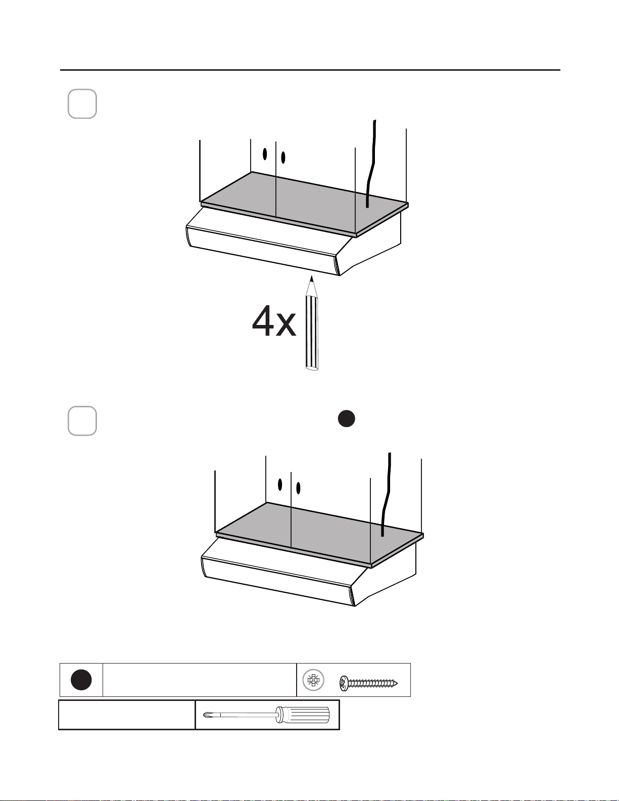
92
0DUTXHORVDJXMHURVSDUD´MDUODFDPSDQDDOPXHEOH9HUL´TXHODPHGLFLyQFRQHO
diagrama de la página anterior.
3
Fije el cuerpo de la campana con 4 tornillos
E
en la parte inferior, disponibles con la
campana.
4
E
7RUQLOORV3R]L[
Destornillador Pozi
MONTAJE DE LA CAMPANA DE COCINA BAJO EL
MUEBLE

93
CONEXIÓN A LA ELECTRICIDAD
Conexión a la corriente de la casa.
¡Precaución! No encienda el interruptor de corriente de la casa hasta que la instala-
ción esté completa.
• Pase el cable de alimentación a través del prepunzonado eléctrico.
Conexiones de la caja de cableado.
• Conecte el cable blanco de la fuente de alimentación (A) al cable blanco de la
campana extractora (D) con un conector de cable de tipo giratorio.
• Conecte el cable negro de la fuente de alimentación al cable negro de la campa-
na extractora (B) con un conector de cable de tipo giratorio (C).
• Conecte el cable de tierra verde (E) (verde y amarillo) debajo del tornillo de
tierra.
1
3
2
Cableado
de la
campana
Sustituya la tapa del compartimento del cableado de campo y los
´OWURVGHJUDVD

94
MANDOS DE FUNCIONAMIENTO
PARA OBTENER LOS MEJORES RESULTADOS
(QFLHQGDODFDPSDQDH[WUDFWRUDYDULRVPLQXWRVDQWHVGHFRFLQDUSDUDGHVDUUROODUXQµXMRGH
aire adecuado. Deje que la campana funcione durante varios minutos después de la cocción
para eliminar el humo y los olores de la cocina.
Botón Función
Botón de apagado del extractor: Apaga el extractor. Se puede operar el extractor
DOSXOVDUFXDOTXLHUDGHORVERWRQHVGHFRQ´JXUDFLyQ
Mantenga pulsado este botón durante 2 segundos para activar la función de
apagado retardado que mantendrá el extractor encendido durante 15 minutos y se
apagará automáticamente.
%RWRQHVGHFRQ´JXUDFLyQGHOH[WUDFWRU9HORFLGDGEDMD
%RWRQHVGHFRQ´JXUDFLyQGHOH[WUDFWRU9HORFLGDGPHGLD
%RWRQHVGHFRQ´JXUDFLyQGHOH[WUDFWRU9HORFLGDGDOWD
Mantenga pulsado el botón durante 2 segundos para activar la MÁXIMA VELO-
&,'$'TXHHVWiSURJUDPDGDSDUDIXQFLRQDUGXUDQWHPLQXWRV$O´QDOGHHVWH
tiempo volverá automáticamente a la velocidad establecida antes. Adecuada para
tratar con niveles de humos de cocina elevados.
%RWyQGHLOXPLQDFLyQLQWHUUXSWRUGHHQFHQGLGRDSDJDGRSDUDODVOXFHV/('3XOVH
el botón ILUMINACIÓN para encender la luz y nuevamente para apagarla.
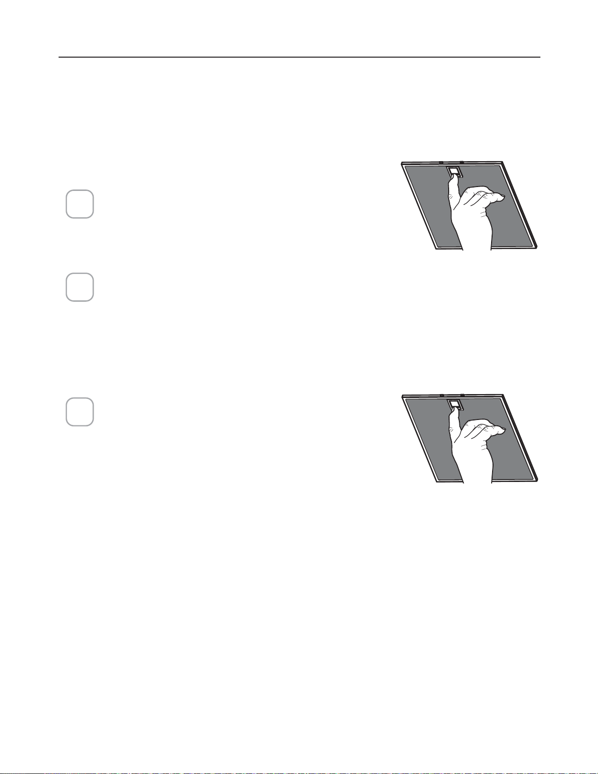
95
CUIDADO DE LOS FILTROS
5HWLUHHO´OWURWLUDQGRGHOSHVWLOORKDFLDDGH-
lante y tirando hacia abajo al mismo tiempo.
/DYHHO´OWURVLQGREODUOR'pMHORVHFDUFRP-
pletamente antes de volver a instalarlo. Si la
VXSHU´FLHGHO´OWURFDPELDGHFRORUFRQHO
WLHPSRODH´FDFLDQRVHYHUiDIHFWDGD
3DUDUHLQVWDODUHO´OWURHPSXMHHO´OWURKDFLD
arriba mientras tira del pestillo hacia ade-
lante, y luego suelte el pestillo para que se
trabe en su lugar.
1
2
3
LIMPIEZA DE LOS FILTROS DE GRASA METÁLICOS
/RV´OWURVGHJUDVDPHWiOLFRVSXHGHQOLPSLDUVHFRQXQDVROXFLyQGHGHWHU-
gente caliente o lavarse en el lavavajillas.
Se deben limpiar cada 2 meses de uso, o más frecuentemente si el uso es
particularmente pesado.
NOTAS:
/DOLPSLH]DHQHOODYDYDMLOODVSXHGHRSDFDUHODFDEDGRGHORV´OWURVGH
grasa metálicos.
$VHJ~UHVHGHTXHORV´OWURVHVWpQFRPSOHWDPHQWHVHFRVDQWHVGHLQVWD-
larlos de nuevo en la campana extractora.
LIMPIEZA DE LAS SUPERFICIES EXTERIORES
Por favor, tenga en cuenta que los abrasivos y los desengrasantes pueden
rayar los acabados de la campana y no deben ser usados para limpiar las
VXSHU´FLHVFRQDFDEDGR
Instrucciones de limpieza del acabado de acero inoxidable:
/LPSLHODVVXSHU´FLHVH[WHULRUHVFRQXQOLPSLDGRUGHDFHURLQR[LGDEOHGLV-
ponible en el mercado.
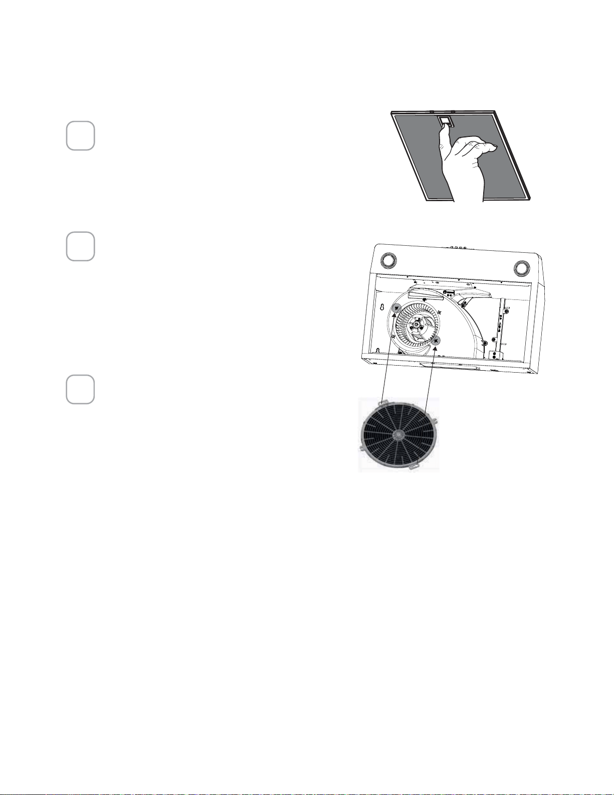
96
SUSTITUCIÓN DEL FILTRO DE CARBÓN ACTIVADO
/RV´OWURVGHFDUEyQDFWLYDGRQRVRQODYDEOHV\QRSXHGHQVHUUHJHQHUDGRV
Se deben sustituir aproximadamente cada 4 meses de funcionamiento, o más
frecuentemente con un uso intensivo.
5HWLUHORV´OWURVGHJUDVD
5HWLUHHO´OWURGHFDUEyQ
viejo quitando los dos torni-
llos y luego instale el nuevo
´OWURXWLOL]DQGRORVPLVPRV
dos agujeros para tornillos.
9XHOYDDLQVWDODUORV´OWURV
de grasa.
1
2
3
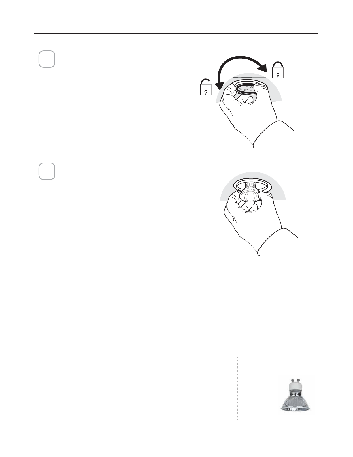
97
SUSTITUCIÓN DE LAS LÁMPARAS
1
Lámpara LED de 5 W tipo GU10
Retire la lámpara (Ver la imagen).
Sustituya la lámpara por una nueva
del mismo tipo, asegurándose de in-
sertar correctamente las dos clavijas
en los alojamientos del portalámpar-
as y de girarla para que se bloquee
de nuevo en su sitio.
Atención: Las lámparas pueden estar
calientes, por favor espere unos minu-
tos antes de sustituirlas
2
Lámparas LED au-
tobalastradas Gu10
- listadas de
acuerdo con
XOQP[
MDQFH
csa c22.2
1¢
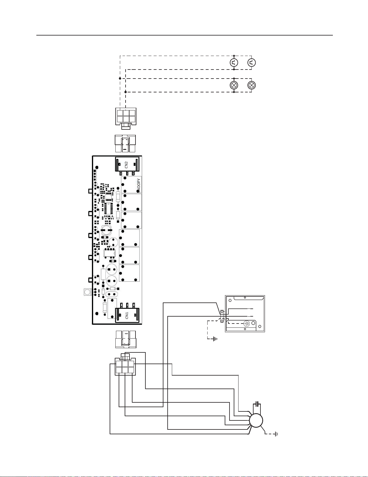
98
DIAGRAMA DE CABLEADO
3&%
#-6
#38
.7
.0503
#-6
8)5(3:
03(
3&%
#38#-,
8)5(3:
#-6
03(
#-,7-5
8*3*/(
#09
:(
3&%8)5
-*/&
7BD)[
#38#-,
03(3&%
)"-0(&/
-".147
03(7-5
03(3&%
-&%
-".147
03(7-5

99
GARANTÍA Y SERVICIO AL CONSUMIDOR FABER
Todos los productos Faber están garantizados contra cualquier defecto de materiales o mano de obra
para el comprador original por un período de 1 año a partir de la fecha de compra original (requiere
prueba de compra). Esta garantía cubre mano de obra y piezas de repuesto. Faber, a su elección, puede
reparar o reemplazar el producto o componentes necesarios para restaurar el producto en buenas
condiciones de trabajo. Para obtener el servicio de garantía, póngase en contacto con el distribuidor de
quien adquirió la campana extractora o con el distribuidor local de Faber. Si no puede identificar a un
distribuidor local de Faber, comuníquese con nosotros al (508) 358-5353 para obtener el nombre de un
distribuidor en su área.
Lo siguiente no está cubierto por la garantía de Faber:
1. Llamadas de servicio para corregir la instalación de su campana extractora, para instruirle sobre
cómo usar su campana extractora, para reemplazar o reparar fusibles de la casa o para corregir el
cableado de la casa o la plomería.
2. Llamadas de servicio para reparar o reemplazar las bombillas, fusibles o filtros de la campana extrac-
tora. Estas partes de consumibles están excluidas de la cobertura de la garantía.
3. Reparaciones, cuando su campana extractora se utiliza para uso doméstico distinto al normal.
4. Daños resultantes de accidente, alteración, mal uso, abuso, incendio, inundación, eventos naturales,
instalación incorrecta, instalación no conforme a los códigos eléctricos o de plomería o la documen-
tación de Faber, o uso de productos no aprobados por Faber.
5. Piezas de repuesto o costos de mano de obra de reparación para unidades operadas fuera de los Es-
tados Unidos o Canadá, incluyendo cualquier campana de cocina Faber no aprobada por UL o C-UL.
6. Reparaciones a la campana resultantes de modificaciones no autorizadas a la misma.
7. Gastos de viaje y transporte para el servicio del producto en lugares remotos, y gastos de recogida y
entrega. Las campanas de cocina Faber deben ser reparadas en el hogar.
ESTA GARANTÍA NO PERMITE LA RECUPERACIÓN DE DAÑOS INCIDENTALES O CONSECUENTES,
INCLUYENDO, SIN LIMITACIÓN, DAÑOS DIRECTOS, INDIRECTOS, INCIDENTALES, ESPECIALES O
CONSECUENTES, LESIONES PERSONALES O MUERTE INCORRECTA O BENEFICIOS PERDIDOS. LA
GARANTÍA DE FABER SE LIMITA A LAS CONDICIONES ANTERIORES Y AL PERÍODO DE GARANTÍA
ESPECIFICADO AQUÍ Y ES EXCLUSIVA. EXCEPTO DADO LO EXPRESAMENTE ESPECIFICADO EN
ESTE ACUERDO, FABER RENUNCIA A TODAS LAS CONDICIONES, REPRESENTACIONES Y GARAN-
TÍAS EXPRESAS O IMPLÍCITAS INCLUYENDO, SIN LIMITACIÓN, CUALQUIER GARANTÍA IMPLÍCITA DE
COMERCIABILIDAD O ADECUACIÓN PARA UN PROPÓSITO PARTICULAR.
Esta garantía le otorga derechos legales específicos que pueden variar de estado a estado.
Modelo: ________________________ Número de serie ________________________
GARANTÍA

991.0675.523_01 - 220302
D00008478_00