Loading ...
Loading ...
Loading ...
Section 2 - OPERATING INSTRUCTIONS
2.2
STARTING, OPERATION & STOPPING
(RECOIL START MODELS)
(Go to Page 9 for Electric Start Models)
(Continued From Previous Page)
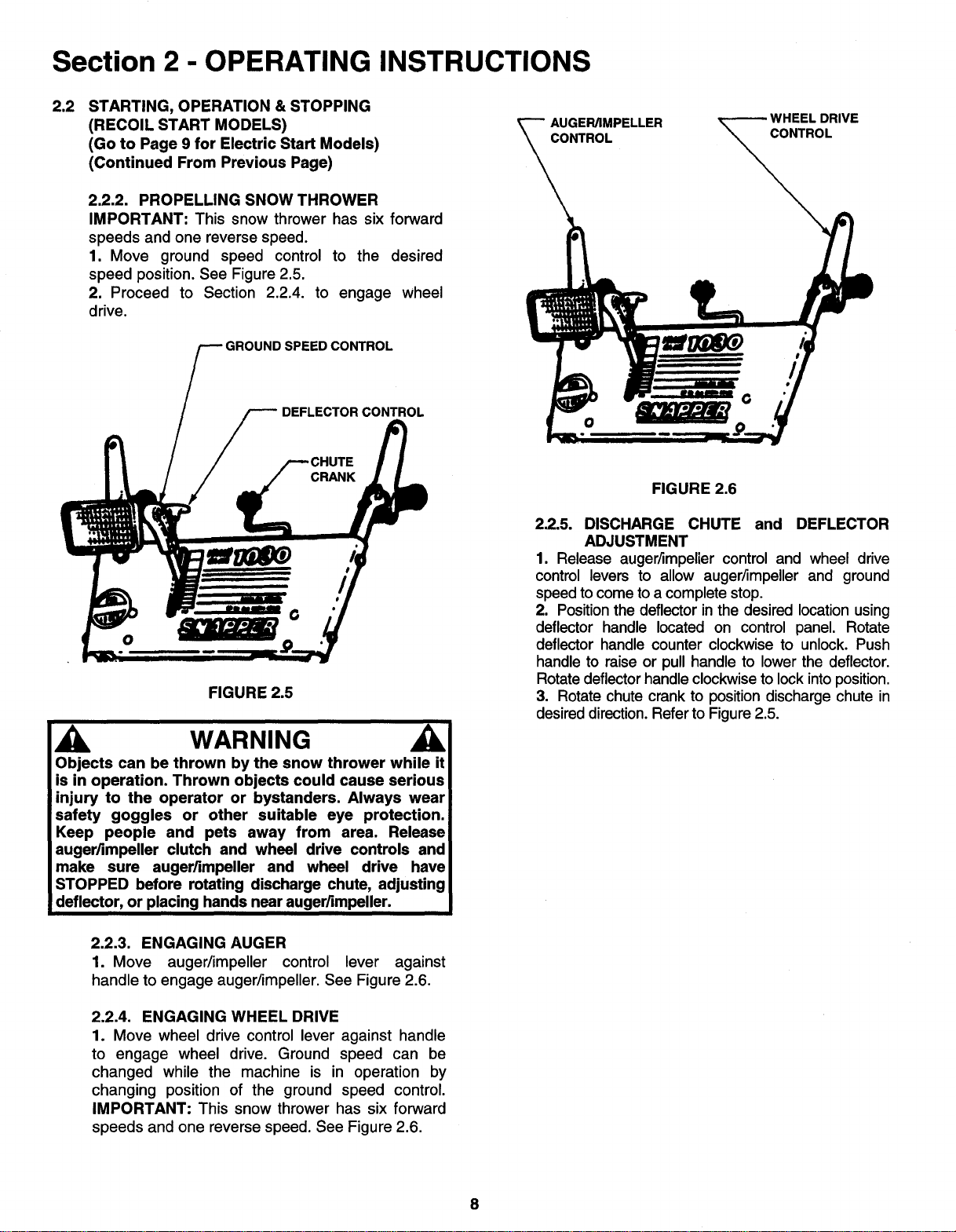
2.2.2. PROPELLING SNOW THROWER
IMPORTANT: This snow thrower has six forward
speeds and one reverse speed.
1. Move ground speed control to the desired
speed position. See Figure 2.5.
2. Proceed to Section 2.2.4. to engage wheel
drive.
GROUNDSPEEDCONTROL
AUGER/IMPELLER
CONTROL
RIVE
DEFLECTOR CONTROL
O
FIGURE 2.5
WARNING
Objects can be thrown by the snow thrower while it
is in operation. Thrown objects could cause serious
injury to the operator or bystanders. Always wear
safety goggles or other suitable eye protection.
i
Keep people and pets away from area. Release i
auger/impeller clutch and wheel drive controls and
make sure auger/impeller and wheel drive have
STOPPED before rotating discharge chute, adjusting
deflector, or placing hands near auger/impeller.
2.2.3. ENGAGING AUGER
1. Move auger/impeller control lever against
handle to engage auger/impeller. See Figure 2.6.
2.2.4. ENGAGING WHEEL DRIVE
1. Move wheel drive control lever against handle
to engage wheel drive. Ground speed can be
changed while the machine is in operation by
changing position of the ground speed control.
IMPORTANT: This snow thrower has six forward
speeds and one reverse speed. See Figure 2.6.
FIGURE 2.6
2.2.5. DISCHARGE CHUTE and DEFLECTOR
ADJUSTMENT
1. Release auger/impeller control and wheel drive
control levers to allow auger/impeller and ground
speed tocome toa complete stop.
2. Positionthe deflector in the desired locationusing
deflector handle located on control panel. Rotate
deflector handle counter clockwise to unlock. Push
handle to raise or pull handle to lower the deflector.
Rotate deflectorhandleclockwiseto lock intoposition.
3. Rotate chute crank to positiondischarge chute in
desireddirection.Refer to Figure2.5.
Loading ...
Loading ...
Loading ...