Loading ...
Loading ...
Loading ...
Section 4 - REPAIR & ADJUSTMENTS
4.1.6. SINGLE HANDLE CONTROL ADJUSTMENT
IMPORTANT: Standing in the operator's position, the left
handle bar lever is for wheel drive engagement and
disengagement. The right handle bar lever is for
auger/impellerengagement and disengagement. Hold both
levers down to handle bar for engagement and release
levers for disengagement. When both levers are pressed
down to the handle bar at the same time, the operatorcan
release the right hand lever and the right lever will remain
engaged as long as the left hand lever is held down to
handle bar. Release the left hand lever and both levers will
disengage.
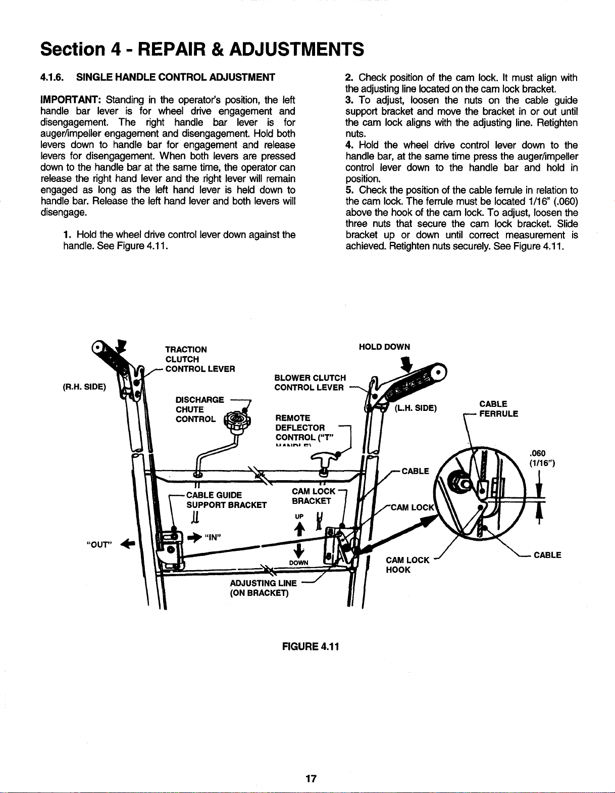
1. Hold the wheel drive control lever downagainst the
handle. See Figure 4.11.
2. Check position of the cam lock. It must align with
the adjustinglinelocatedon the cam lock bracket.
3. To adjust, loosen the nuts on the cable guide
support bracket and move the bracket in or out until
the cam lock aligns with the adjusting line. Retighten
nuts.
4. Hold the wheel drive control lever down to the
handle bar, at the same time press the auger/impeller
control lever down to the handle bar and hold in
position.
5. Check the positionof the cable ferrule in relationto
the cam lock.The ferrule must be located 1/16" (.060)
above the hookof the cam lock.To adjust, loosenthe
three nuts that secure the cam lock bracket. Slide
bracket up or down until correct measurement is
achieved. Retightennutssecurely. See Figure4.11.
(R.H. SIDE)
TRACTION
CLUTCH
_- CONTROL LEVER
DISCHARGE
CHUTE
CONTROL
BLOWER CLUTCH
CONTROL LEVER
REMOTE
DEFLECTOR
CONTROL("T"
uAkm_m _
HOLD DOWN
(L.H. SIDE)
CABLE
FERRULE
.060
(1/16")
JIDE
SUPPORT BRACKET
It
CAM
BRACKET
uP
+
DOWN
ADJUSTING LINE
(ON BRACKET)
LOCP
CAM LOCK
HOOK
CABLE
FIGURE 4.11
17
Loading ...
Loading ...
Loading ...