perator's
I:RnFrSMRN°
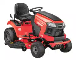
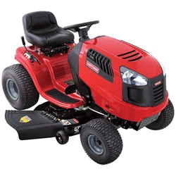
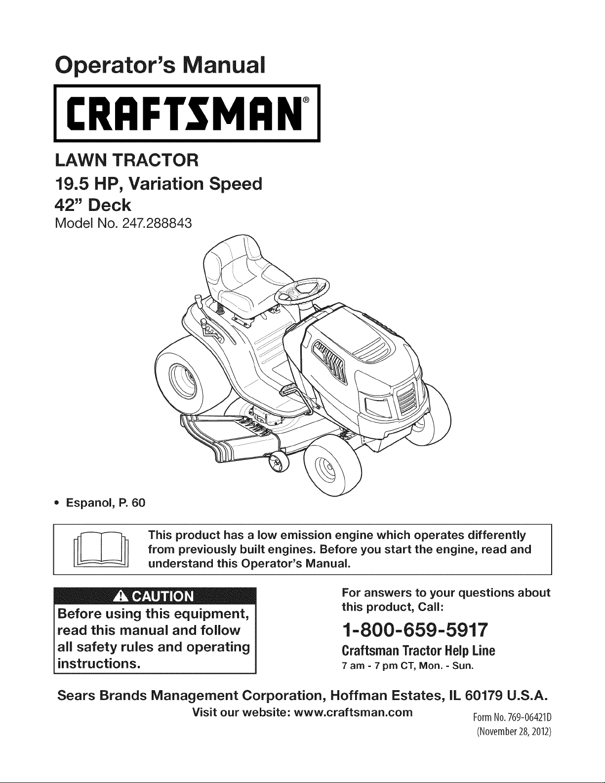
LAWN TRACTOR
19.5 HP, Variation Speed
42" Deck
Model No. 247.288843
• Espanol, P. 60
This product has a low emission engine which operates differently
from previously built engines. Before you start the engine, read and
understand this Operator's Manual.
Before using this equipment,
read this manual and follow
all safety rules and operating
instructions.
For answers to your questions about
this product, Call:
1-800=659=5917
Craftsman Tractor Help Line
7 am = 7 pm CT, Mort. =Sun.
Sears Brands Management Corporation, Hoffman Estates, IL 60179 U.S.A.
Visit our website: www.craftsman.com FormNo.769-06421D
(November28,2012)
Warranty Statement .......................................................... 2
Safety Instructions ............................................................ 3
Slope Gauge ..................................................................... 8
Assembly ........................................................................... 9
Operation ........................................................................ 11
Service and Maintenance .............................................. 17
Off-Season Storage ........................................................ 26
Trou bleshooting .............................................................. 27
Labels ............................................................................. 28
Parts List ......................................................................... 30
Espa_ol ............................................................................ 60
Service Numbers ............................................. Back Cover
CRAFTSMAN FULL WARRANTY
FORTWOYEARSfromthe dateof purchase,all non-expendablepartsof this ridingequipmentarewarrantedagainstany defectsin materialor
workmanship.A defectivenon-expendablepart will receivefree in-homerepairor replacementif repairis unavailable.
BATTERYLIMITEDWARRANTY
FOR90 DAYSfromthe dateof purchase,the battery(anexpendablepart)of this ridingequipmentis warrantedagainstany defectsin materialor
workmanship.A newbatterywill besuppliedfree of charge.Youare responsibleforthe laborcost of batteryinstallation.
ADDITIONALLIMITEDWARRANTIES
inthe followingadditionalwarranties,youare responsiblefor the laborcost of part installationafter the secondyearfromthe dateof purchase.
FORFiVEYEARSfrom thedate of purchase,the frameof this ridingequipmentiswarrantedagainstany defectsin materialorworkmanship.A
newframe willbe suppfiedfreeof charge.
FORTENYEARSfromthe dateof purchase,thefrontaxle of this riding equipmentis warrantedagainstany defectsin materialor workmanship.
A newfront axlewill be suppliedfreeof charge.
FORASLONGASITiSUSEDbytheoriginalownerafterthetenthyearfromthedateofpurchase,thecastironfrontaxle(if equipped)of thisriding
equipmentis warrantedagainstanydefectsinmaterialorworkmanship.Withproofofpurchase,anewcastironfrontaxlewillbe suppliedfreeofcharge.
WARRANTYSERVICE
Forwarrantycoveragedetailsto obtainfree repairor replacement,carl 1-800-659-5917or visitthe web site:www.craftsman.com
inall casesabove,if part repairor replacementis impossible,the ridingequipmentwill be replacedfreeof chargewith the sameor anequivalent
model.
All ofthe abovewarrantycoverageis void if this ridingequipmentis everusedwhileprovidingcommercialservicesor if rentedto anotherperson.
ThiswarrantycoversONLYdefectsin materialandworkmanship.Warrantycoveragedoes NOTinclude:
• Expendableparts(exceptbattery)thatcan wearoutfromnormalusewithinthewarrantyperiod,includingbut not limitedto blades,spark
plugs,air cleaners,belts,and oil filters.
• Standardmaintenanceservicing,oilchanges,or tune-ups.
Tire replacementor repaircausedby puncturesfromoutsideobjects,suchas nails,thorns,stumps,or glass.
• Tireor wheelreplacementor repairresultingfrom normalwear,accident,or improperoperationor maintenance.
Repairsnecessarybecauseof operatorabuse,includingbut notlimitedto damagecausedbytowingobjectsbeyondthe capabilityof the
ridingequipment,impactingobjectsthat bendthe frame,axle assemblyor crankshaft,or over-speedingthe engine.
Repairsnecessarybecauseof operatornegligence,includingbutnot limitedto,electricaland mechanicaldamagecausedby improper
storage,failureto usethe propergradeand amountof engineoil,failureto keepthe deck clearof flammabledebris, or failureto maintainthe
ridingequipmentaccordingto the instructionscontainedin the operator'smanual.
• Engine(fuel system)cleaningor repairscausedbyfuel determinedto becontaminatedor oxidized(stale). ingeneral,fuel shouldbeused
within30 daysof itspurchasedate.
• Normaldeteriorationandwearof the exteriorfinishes,or productlabelreplacement.
Thiswarrantygivesyou specificlegalrights,and youmayalsohaveotherrightswhichvaryfromstateto state.
Sears Brands ManagementCor
EngineOil: SAE30
Fuel: UnleadedGasoline
SparkPlug: Champion®RC12YC
_oration,Hoffman Estates, IL 60179
Model Number:
Serial Number:
Dateof Purchase:
Recordthe modelnumber,serialnumber,
anddateof purchaseabove.
© SearsBrands,LLC 2
Thissymbolpointsout importantsafetyinstructionswhich,if not
followed,couldendangerthepersonalsafetyand/orpropertyof
yourselfandothers. Readandfollowall instructionsin thismanual
beforeattemptingto operatethismachine.Failureto complywith
theseinstructionsmayresultin personalinjury.Whenyou seethis
symbol,HEEDITSWARNING!
CALIFORNIA PROPOSITION 65
EngineExhaust,someof itsconstituents,and certainvehicle
componentscontainoremit chemicalsknownto Stateof California
to cause cancerand birthdefectsor other reproductiveharm.
Batteryposts,terminals,and relatedaccessoriescontainleadand
leadcompounds,chemicalsknownto the Stateof Californiato
causecancerand reproductiveharm.Washhandsafter handling.
Thismachinewasbuiltto be operatedaccordingto the safeopera-
tion practicesin this manual.As withanytypeof powerequipment,
carelessnessorerroron the partof the operatorcan resultin serious
injury.Thismachineis capableof amputatingfingers,hands,toes
andfeet and throwingdebris.Failureto observethe followingsafety
instructionscouldresultin seriousinjuryor death.
Your Responsibility--Restrictthe use of thispowermachineto
personswho read,understandand follow thewarningsand instruc-
tionsin this manualand on the machine.
SAVE THESE INSTRUCTIONS!
GENERAL OPERATION
• Read,understand,andfollowall instructionson the machineand
in themanual(s)beforeattemptingto assembleandoperate.
Keepthis manualina safe placefor futureand regularreference
andfor orderingreplacementparts.
• Befamiliarwithall controlsandtheir properoperation.Knowhow
to stop the machineanddisengagethemquickly.
• Neverallowchildrenunder 14 yearsold to operatethis machine.
Children14yearsoldand over shouldreadand understandthe
operationinstructionsandsafetyrulesin this manualandshould
betrainedandsupervisedbya parent.
• Neverallowadultsto operatethis machinewithoutproper
instruction.
• Tohelpavoidbladecontactor a thrownobjectinjury,keep
bystanders,helpers,childrenandpetsat least75 feet fromthe
machinewhile it is in operation.Stopmachineif anyoneenters
the area.
• Thoroughlyinspectthe area wherethe equipmentis to be used.
Removeallstones,sticks,wire,bones,toys,and otherforeign
objectswhichcouldbe pickedupand thrownby the blade(s).
Thrownobjectscan causeseriouspersonalinjury.
• Planyour mowingpatternto avoiddischargeof materialtoward
roads,sidewalks,bystandersandthe like.Also,avoiddischarg-
ingmaterialagainstawall orobstructionwhichmaycause
dischargedmaterialto ricochetback towardthe operator.
• Alwayswear safetyglassesor safetygogglesduringoperation
andwhile performingan adjustmentor repairto protectyoureyes.
Thrownobjectswhich ricochetcancauseseriousinjuryto the
eyes.
• Wearsturdy,rough-soledwork shoesand close-fittingslacksand
shirts.Loosefittingclothesandjewelry canbe caughtin movable
parts.Neveroperatethis machinein bare feet or sandals.
• Be awareof the mowerandattachmentdischargedirectionand
do not pointit at anyone.Donot operatethe mowerwithoutthe
dischargecoveror entiregrasscatcherin its properplace.
Donot put handsor feet near rotatingpartsor underthe cutting
deck. Contactwiththe blade(s)can amputatehandsandfeet.
A missingor damageddischargecovercan causebladecontact
or thrownobjectinjuries.
• Stoptheblade(s)whencrossinggraveldrives,walks,or roads
andwhile notcuttinggrass.
• Watchfor trafficwhenoperatingnear or crossingroadways.This
machineis not intendedfor useonany public roadway.
• Donot operatethe machinewhile underthe influenceof alcohol
or drugs.
• Mowonly indaylightorgoodartificiallight.
Nevercarrypassengers.
• Disengageblade(s)beforeshiftinginto reverse.Backup slowly.
Alwayslookdownandbehindbeforeandwhile backingto avoida
back-overaccident.
3
• Slowdownbeforeturning.Operatethe machinesmoothly.Avoid
erraticoperationandexcessivespeed.
Disengageblade(s),setparkingbrake,stopengineandwaituntil
the blade(s)come to a completestopbeforeremovinggrass
catcher,emptyinggrass,uncloggingchute,removinganygrassor
debris,or makinganyadjustments.
Neverleavea runningmachineunattended.Alwaysturnoff
blade(s),setparkingbrake,stopengineand removekeybefore
dismounting.
Useextracare whenloadingorunloadingthe machineintoa
traileror truck. This machineshouldnot bedrivenupor down
ramp(s),becausethe machinecouldtip over,causingserious
personalinjury.The machinemustbe pushedmanuallyon
ramp(s)to loador unloadproperly.
Mufflerandenginebecomehotandcan causea burn.Do not
touch.
Checkoverheadclearancescarefullybeforedrivingunderlow
hangingtree branches,wires,dooropeningsetc.,wherethe
operatormaybe struckor pulledfrom the machine,whichcould
resultinseriousinjury.
Disengageallattachmentclutchesanddepressthe brakepedal
completelybeforeattemptingto start engine.
Yourmachineisdesignedto cut normalresidentialgrass of a
heightno morethan 10".Do not attemptto mowthroughunusually
tall,dry grass (e.g.,pasture)or piles of dry leaves.Drygrassor
leavesmaycontactthe engineexhaustand/or buildup on the
mowerdeckpresentinga potentialfire hazard.
Useonlyaccessoriesand attachmentsapprovedfor this machine
by the machinemanufacturer.Read,understandandfollowall
instructionsprovidedwiththe approvedaccessoryor attachment.
Fora list of approvedaccessoriesandattachments,call 1-800-
659-5917.
Dataindicatesthatoperators,age60years and above,are
involvedin a largepercentageof ridingmower-relatedinjuries.
Theseoperatorsshouldevaluatetheirabilityto operatethe riding
mowersafelyenoughto protectthemselvesandothersfrom
seriousinjury.
If situationsoccurwhichare not coveredinthis manual,usecare
andgoodjudgment.
SLOPE OPERATION
Slopesare a majorfactorrelatedto lossof controlandtip-over
accidentswhichcan result in severeinjuryor death.Allslopes require
extracaution.Ifyoucannotback up the slopeor if youfeel uneasyon
it, do not mowit.
Foryoursafety,use the SlopeGuideincludedas partof this manual
to measureslopesbeforeoperatingthis machineon a slopedor hilly
area. If the slopeis greaterthan15degreesas shownonthe Slope
Guide,do notoperatethis machineon thatareaor seriousinjurycould
result.
Do:
o
Mowupand down slopes,not across.Exerciseextremecaution
whenchangingdirectionon slopes.
• Watchfor holes,ruts,bumps,rocks,orother hiddenobjects.
Uneventerraincouldoverturnthe machine.Tallgrasscan hide
obstacles.
Useslowspeed.Choosea lowenoughspeedsettingso that
you will nothaveto stop or shiftwhileon the slope.Tiresmay
lose tractionon slopeseventhoughthe brakesare functioning
properly.Alwayskeepmachinein gearwhen goingdownslopes
to take advantageof enginebrakingaction.
• Followthe manufacturer'srecommendationsfor wheelweightsor
counterweightsto improvestability.
Useextracarewithgrasscatchersor otherattachments.These
can changethe stabilityof the machine.
Keepallmovementon the slopesslowand gradual.Do not make
suddenchangesin speedor direction.Rapidengagementor
brakingcouldcausethe frontof the machineto lift and rapidlyflip
overbackwardswhichcouldcauseseriousinjury.
• Avoidstartingorstoppingona slope. If tires losetraction,disen-
gagethe blade(s)and proceedslowlystraightdownthe slope.
DoNot:
• Donot turnon slopesunlessnecessary;then,turnslowlyand
graduallydownhill,if possible.
• Donot mow neardrop-offs,ditchesor embankments.The mower
could suddenlyturnover if a wheelis overthe edgeof a cliff,
ditch,or if an edgecavesin.
• Donot try to stabilizethe machineby puttingyourfooton the
ground.
• Donot usea grasscatcheron steepslopes.
• Donot mowon wet grass.Reducedtractioncouldcausesliding.
• Donot attemptto coastdownhill.Over-speedingmaycausethe
operatorto lose controlof the machineresultingin seriousinjury
or death.
• Donot tow heavypull behindattachments(e.g.loadeddumpcart,
lawn roller,etc.)on slopesgreaterthan5 degrees.Whengoing
down hill,the extraweighttends to pushthe tractorand may
causeyou to loosecontrol(e.g. tractormayspeedup, brakingand
steeringabilityare reduced,attachmentmayjack-knifeandcause
tractorto overturn).
4
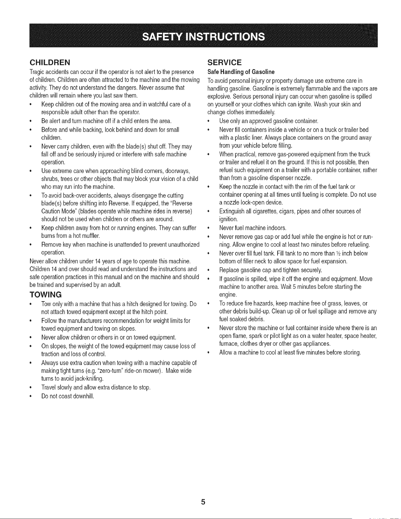
CHILDREN
Tragicaccidentscanoccurifthe operatoris notalert to the presence
of children.Childrenare often attractedto the machineand the mowing
activity.Theydo notunderstandthe dangers.Neverassumethat
childrenwill remainwhereyou last sawthem.
• Keepchildrenout of the mowingareaand inwatchfulcare of a
responsibleadultotherthanthe operator.
• Bealert andturnmachineoff ifa childentersthe area.
• Beforeandwhilebacking,lookbehindand downfor small
children.
Nevercarrychildren,evenwiththe blade(s)shutoff.They may
fall off and be seriouslyinjuredorinterferewithsafe machine
operation.
• Useextremecarewhenapproachingblindcorners,doorways,
shrubs,treesor otherobjectsthat may block yourvisionof a child
whomay run intothe machine.
Toavoidback-overaccidents,alwaysdisengagethe cutting
blade(s)beforeshiftingintoReverse.If equipped,the "Reverse
CautionMode"(bladesoperatewhilemachineridesinreverse)
shouldnotbe usedwhenchildrenor othersare around.
Keepchildrenawayfrom hotor runningengines.They cansuffer
burnsfroma hotmuffler.
• Removekeywhenmachineisunattendedto preventunauthorized
operation.
Neverallowchildrenunder 14 yearsof ageto operatethis machine.
Children14andovershouldreadand understandthe instructionsand
safeoperationpracticesinthismanualandon the machineandshould
betrainedandsupervisedbyan adult.
TOWING
Towonlywith a machinethat hasa hitch designedfor towing.Do
not attachtowedequipmentexceptat the hitchpoint.
Followthe manufacturersrecommendationforweightlimitsfor
towedequipmentandtowingonslopes.
Neverallowchildrenor othersin or on towedequipment.
Onslopes,theweightof thetowedequipmentmaycauselossof
tractionandloss of control.
Alwaysuseextra cautionwhentowingwitha machinecapableof
makingtightturns (e.g."zero-turn"ride-onmower). Makewide
turnsto avoidjack-knifing.
Travelslowlyandallowextradistanceto stop.
Do notcoastdownhill.
SERVICE
SafeHandlingof Gasoline
Toavoidpersonalinjuryor propertydamageuse extremecarein
handlinggasoline.Gasolineisextremelyflammableand the vaporsare
explosive.Seriouspersonalinjurycanoccurwhengasolineis spilled
on yourselforyour clotheswhich can ignite.Washyourskinand
changeclothesimmediately.
• Useonly anapprovedgasolinecontainer.
Neverfill containersinsidea vehicleoron a truckortrailer bed
witha plasticliner.Alwaysplacecontainerson the groundaway
fromyourvehiclebeforefilling.
Whenpractical,removegas-poweredequipmentfrom the truck
or trailerand refueliton theground.Ifthis isnot possible,then
refuelsuchequipmenton a trailerwitha portablecontainer,rather
than froma gasolinedispensernozzle.
Keepthe nozzleincontactwith the rim of the fueltankor
containeropeningat all timesuntilfuelingiscomplete.Donot use
a nozzlelock-opendevice.
Extinguishall cigarettes,cigars,pipesandothersourcesof
ignition.
• Neverfuel machineindoors.
Neverremovegascap or add fuelwhilethe engineis hotor run-
ning.Allowengineto coolat leasttwominutesbeforerefueling.
Neveroverfill fuel tank. Filltank to no morethan 1/2inchbelow
bottomof filler neckto allowspaceforfuel expansion.
• Replacegasolinecap andtightensecurely.
• If gasolineis spilled,wipeitoff the engineand equipment.Move
machineto anotherarea.Wait5 minutesbeforestartingthe
engine.
• To reducefire hazards,keepmachinefree of grass,leaves,or
otherdebrisbuild-up.Cleanup oilor fuel spillageandremoveany
fuel soakeddebris.
• Neverstorethe machineor fuelcontainerinsidewherethere isan
openflame,sparkor pilotlight as on a waterheater,spaceheater,
furnace,clothesdryeror othergasappliances.
Allowa machineto coolat leastfiveminutesbeforestoring.
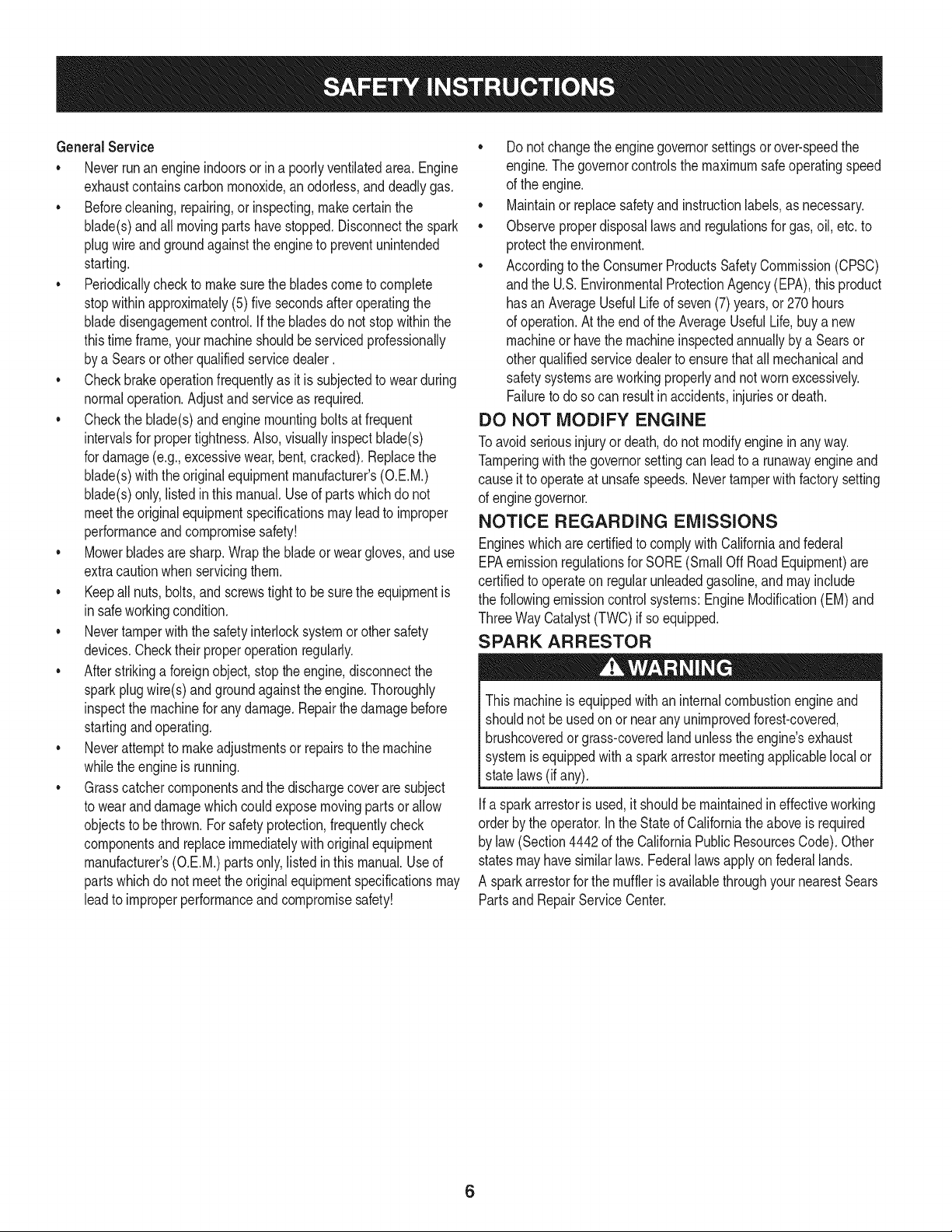
GeneralService
• Neverrunanengineindoorsorina poorlyventilatedarea.Engine
exhaustcontainscarbonmonoxide,anodorless,anddeadlygas.
• Beforecleaning,repairing,orinspecting,makecertainthe
blade(s)andallmovingpartshavestopped.Disconnectthespark
plugwireandgroundagainsttheenginetopreventunintended
starting.
• Periodicallychecktomakesurethebladescometocomplete
stopwithinapproximately(5)fivesecondsafteroperatingthe
bladedisengagementcontrol.Ifthebladesdonotstopwithinthe
thistimeframe,yourmachineshouldbeservicedprofessionally
byaSearsorotherqualifiedservicedealer.
• Checkbrakeoperationfrequentlyasitissubjectedtowearduring
normaloperation.Adjustandserviceasrequired.
• Checktheblade(s)andenginemountingboltsatfrequent
intervalsforpropertightness.Also,visuallyinspectblade(s)
fordamage(e.g.,excessivewear,bent,cracked).Replacethe
blade(s)withtheoriginalequipmentmanufacturer's(O.E.M.)
blade(s)only,listedinthismanual.Useofpartswhichdonot
meettheoriginalequipmentspecificationsmayleadtoimproper
performanceandcompromisesafety!
• Mowerbladesaresharp.Wrapthebladeorweargloves,anduse
extracautionwhenservicingthem.
• Keepallnuts,bolts,andscrewstighttobesuretheequipmentis
insafeworkingcondition.
• Nevertamperwiththe safetyinterlocksystemor othersafety
devices.Checktheir properoperationregularly.
• Afterstrikinga foreignobject,stop the engine,disconnectthe
sparkplugwire(s)and groundagainstthe engine.Thoroughly
inspectthe machinefor anydamage.Repairthe damagebefore
startingandoperating.
• Neverattemptto makeadjustmentsor repairsto the machine
whilethe engineis running.
• Grasscatchercomponentsand the dischargecoverare subject
to wearanddamagewhich couldexposemovingparts or allow
objectsto bethrown.Forsafetyprotection,frequentlycheck
componentsand replaceimmediatelywithoriginalequipment
manufacturer's(O.E.M.)partsonly,listed in this manual.Useof
partswhichdo not meetthe originalequipmentspecificationsmay
leadto improperperformanceand compromisesafety!
• Donot changethe enginegovernorsettingsorover-speedthe
engine.The governorcontrolsthe maximumsafeoperatingspeed
of the engine.
Maintainor replacesafetyand instructionlabels,as necessary.
• Observeproperdisposallawsandregulationsfor gas,oil, etc.to
protecttheenvironment.
• Accordingto the ConsumerProductsSafetyCommission(CPSC)
andthe U.S.EnvironmentalProtectionAgency(EPA),this product
has an AverageUsefulLifeof seven(7)years,or 270hours
of operation.At the endof the AverageUsefulLife,buy anew
machineor havethe machineinspectedannuallybya Searsor
otherqualifiedservicedealerto ensurethatall mechanicaland
safetysystemsare workingproperlyand not wornexcessively.
Failureto do so can resultin accidents,injuriesor death.
DO NOT MODIFY ENGINE
Toavoid seriousinjuryor death,do notmodifyenginein anyway.
Tamperingwiththe governorsettingcanleadto a runawayengineand
causeit to operateat unsafespeeds.Nevertamper with factorysetting
of enginegovernor.
NOTICE REGARDING EMISSIONS
Engineswhicharecertifiedto complywithCaliforniaandfederal
EPAemissionregulationsfor SORE(SmallOffRoadEquipment)are
certifiedto operateon regularunleadedgasoline,and may include
the followingemissioncontrolsystems:EngineModification(EM)and
ThreeWay Catalyst(TWO)if so equipped.
SPARK ARRESTOR
Thismachineisequippedwithan internalcombustionengineand
shouldnot beusedon or near anyunimprovedforest-covered,
brushcoveredor grass-coveredlandunlesstheengine'sexhaust
systemis equippedwith a sparkarrestormeetingapplicablelocalor
statelaws (if any).
Ifa sparkarrestoris used,it shouldbe maintainedin effectiveworking
orderby the operator.Inthe Stateof Californiatheaboveis required
by law (Section4442of the CaliforniaPublicResourcesCode). Other
statesmayhavesimilarlaws.Federallaws applyonfederallands.
A sparkarrestorfor the muffleris availablethroughyournearestSears
PartsandRepairServiceCenter.
6
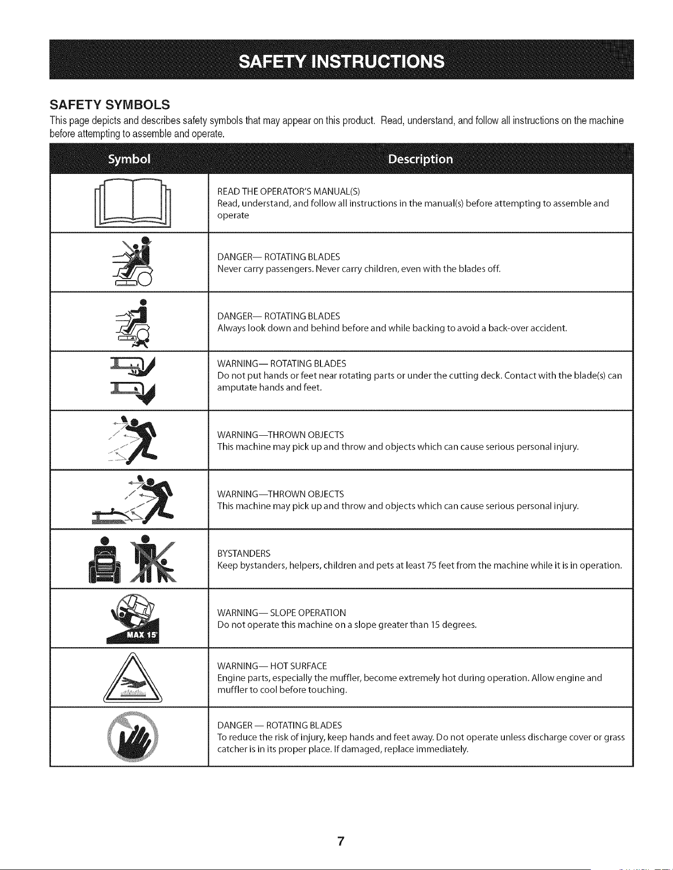
SAFETY SYMBOLS
Thispagedepictsand describessafety symbolsthatmayappearonthis product. Read,understand,andfollowallinstructionson the machine
beforeattemptingto assembleandoperate.
O
A
READ THE OPERATOR'S MANUAL(S)
Read, understand, and follow all instructions in the manual(s) before attempting to assemble and
operate
DANGER-- ROTATING BLADES
Never carry passengers. Never carry children, even with the blades off.
DANGER-- ROTATING BLADES
Always look down and behind before and while backing to avoid a back-over accident.
WARNING-- ROTATING BLADES
Do not put hands or feet near rotating parts or under the cutting deck. Contact with the blade(s) can
amputate hands and feet.
WARNING--THROWN OBJECTS
This machine may pick up and throw and objects which can cause serious personal injury.
WARNING--THROWN OBJECTS
This machine may pick up and throw and objects which can cause serious personal injury.
BYSTANDERS
Keep bystanders, helpers, children and pets at least 75 feet from the machine while it is in operation.
WARNING-- SLOPE OPERATION
Do not operate this machine on a slope greater than 15 degrees.
WARNING-- HOT SURFACE
Engine parts, especially the muffler, become extremely hot during operation. Allow engine and
muffler to cool before touching.
DANGER- ROTATING BLADES
To reduce the risk of injury, keep hands and feet away. Do not operate unless discharge cover or grass
catcher is in its proper place. If damaged, replace immediately.
7
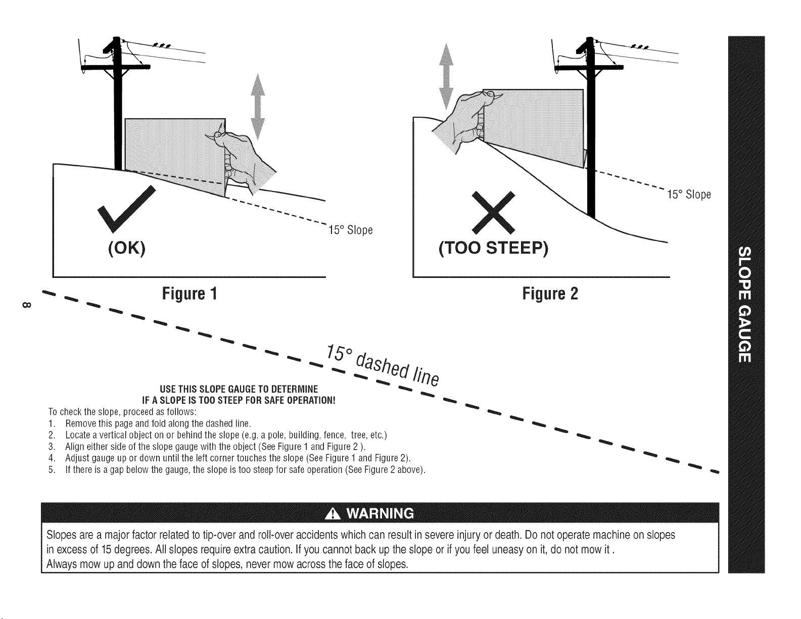
(OK)
15° Slope
X
(TOO STEEP)
15° Slope
'_. _ Figure1
USETHISSLOPEGAUGETODETERMINE
IFA SLOPEIS TOOSTEEPFORSAFEOPERATION!
To checkthe slope, proceedas follows:
1. Removethis pageandfold along the dashedline.
2. Locatea verticalobject onor behindthe slope (e.g. a pole, building,fence, tree, etc.)
3. Align eitherside of the slope gaugewith the object (See Figure1 and Figure2 ).
4. Adjust gaugeup or down until the left cornertouchesthe slope (SeeFigure1and Figure2).
5.
15°
dashed line
If there is agap belowthe gauge,the slope is too steepfor safeoperation(SeeFigure2 above).
Figure2
Slopes are a majorfactor related to tip-over and roll-over accidents which can result in severe injury or death. Do not operatemachine on slopes
in excess of 15 degrees. All slopes require extra caution. If you cannot back up the slope or if you feel uneasy on it, do not mow it.
Always mow up and down the face of slopes, never mow across the face of slopes.
iMPORTANT:Yourtractoris shippedwith motoroil in theengine.
However,you MUSTcheckthe oil levelbeforeoperating.Referto the
Service& Maintenancesectionfor instructionson checkingtheoil
level.
Attaching the Battery Cables
CALIFORNIA PROPOSITION 65
Batteryposts,terminals,andrelatedaccessoriescontainleadand
leadcompounds,chemicalsknownto the Stateof Californiato
causecancerand reproductiveharm.Washhandsafterhandling.
Whenattachingbatterycables,alwaysconnectthe POSITIVE(Red)
wireto its terminalfirst,followedby the NEGATIVE(Black)wire.
Forshippingreasons,bothbatterycablesonyourequipmenthave
beenleft disconnectedfromthe terminalsat the factory.Toconnect
the batterycables,proceedas follows:
NOTE:Thepositivebatteryterminalis markedPos.(+).The negative
batteryterminalis markedNeg.(-).
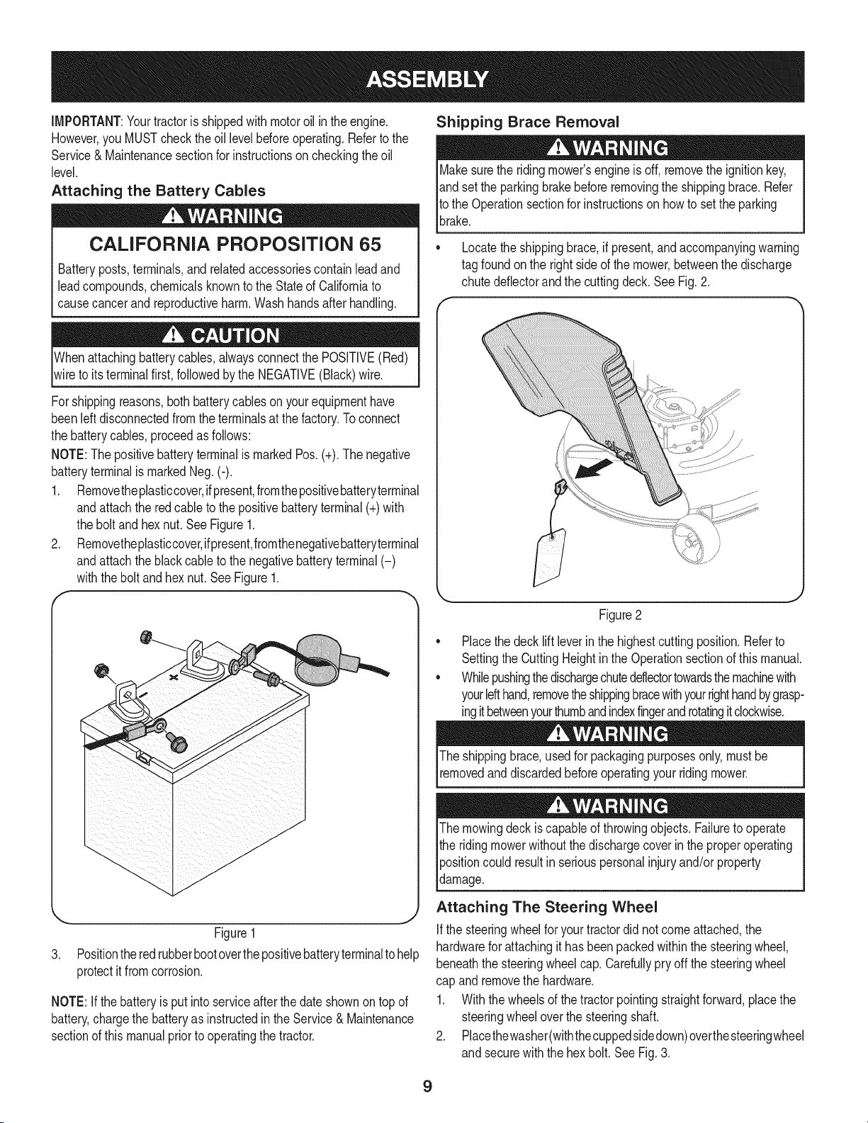
1. Removetheplasticcover,ifpresent,fromthepositivebatteryterminal
andattachthe red cableto the positivebatteryterminal(+)with
the boltand hexnut.SeeFigure1.
2. Removetheplasticcover,ifpresent,fromthenegativebatteryterminal
andattachthe blackcableto thenegativebatteryterminal(-)
withthe boltandhex nut.SeeFigure1.
f
J
Figure1
3. Positionthe redrubberbootoverthepositivebatteryterminalto help
protectit fromcorrosion.
NOTE:If thebatteryis put into serviceafterthe dateshownon top of
battery,chargethe batteryas instructedin the Service& Maintenance
sectionof this manualprior to operatingthe tractor.
Shipping Brace Removal
Makesurethe ridingmower'sengineis off, removetheignitionkey,
andset the parkingbrakebeforeremovingthe shippingbrace.Refer
Itothe Operationsectionfor instructionsonhowto setthe parking
lbrake.
• Locatethe shippingbrace,if present,andaccompanyingwarning
tag foundonthe rightsideof the mower,betweenthe discharge
chutedeflectorand the cuttingdeck. See Fig. 2.
Figure2
Placethe deck lift leverinthe highestcuttingposition.Referto
SettingtheCuttingHeightin the Operationsectionof thismanual.
Whilepushingthedischargechuteddlectortowardsthemachinewith
yourlefthand,removetheshippingbracewithyourrighthandbygrasp-
ingitbetweenyourthumbandindexfingerandrotatingitclockwise.
The shippingbrace,usedfor packagingpurposesonly,mustbe
removedand discardedbeforeoperatingyour ridingmower.
The mowingdeck iscapableof throwingobjects.Failureto operate
the ridingmowerwithoutthe dischargecoverin the properoperating
Ipositioncould resultin seriouspersonalinjuryand/orproperty
ldamage.
Attaching The Steering Wheel
Ifthe steeringwheelfor yourtractordid notcome attached,the
hardwarefor attachingit has beenpackedwithinthe steeringwheel,
beneaththe steeringwheelcap.Carefullypry off the steeringwheel
cap and removethe hardware.
1. Withthe wheelsof the tractorpointingstraightforward,placethe
steeringwheeloverthe steeringshaft.
2. Placethewasher(withthecuppedsidedown)overthesteeringwheel
and securewiththe hex bolt. See Fig. 3.
9
f
\
Figure3
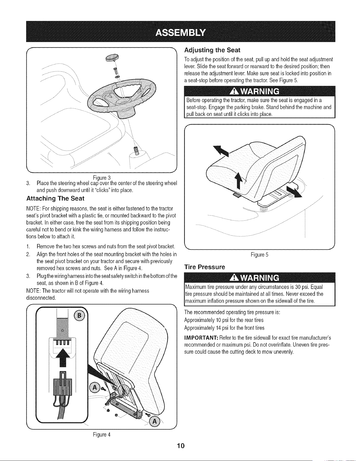
3. Placethe steeringwheelcap overthe centerof the steeringwheel
andpushdownwarduntil it "clicks"into place.
Attaching The Seat
NOTE:Forshippingreasons,the seat is eitherfastenedtothe tractor
seat'spivotbracketwitha plastictie, or mountedbackwardto the pivot
bracket.Ineithercase,free the seatfrom its shippingpositionbeing
carefulnotto bendor kink the wiringharnessandfollowtheinstruc-
tionsbelowto attach it.
1. Removethetwo hexscrewsandnuts fromthe seatpivot bracket.
2. Alignthefrontholesof the seatmountingbracketwith the holesin
the seat pivotbracketon yourtractorand securewith previously
removedhex screwsandnuts. See A in Figure4.
3. Plugthewiringharnessintotheseatsafetyswitchinthebottomofthe
seat,as shownin Bof Figure4.
NOTE:The tractorwill not operatewiththe wiringharness
disconnected.
Adjusting the Seat
Toadjust the positionof the seat,pullupandholdthe seat adjustment
lever.Slidethe seatforwardor rearwardto thedesiredposition;then
releasethe adjustmentlever.Makesure seatis lockedintopositionin
a seat-stopbeforeoperatingthe tractor.See Figure5.
Beforeoperatingthe tractor,makesurethe seat is engagedina
seat-stop.Engagethe parkingbrake.Standbehindthe machineand
pull backon seatuntil it clicksintoplace.
Figure5
Tire Pressure
Maximumtire pressureunderany circumstancesis 30 psi. Equal
tire pressureshouldbe maintainedat all times. Neverexceedthe
_maxmum nfat on pressureshownon the s dewa of thet re.
The recommendedoperatingtire pressureis:
Approximately10psi forthe reartires
Approximately14psi forthe fronttires
iMPORTANT: Referto the tire sidewallfor exacttire manufacturer's
recommendedormaximumpsi.Donot overinfiate.Uneventirepres-
surecouldcausethe cuttingdeckto mowunevenly.
Figure4
10
.I
G
A
©
H
F
B
D
E
F
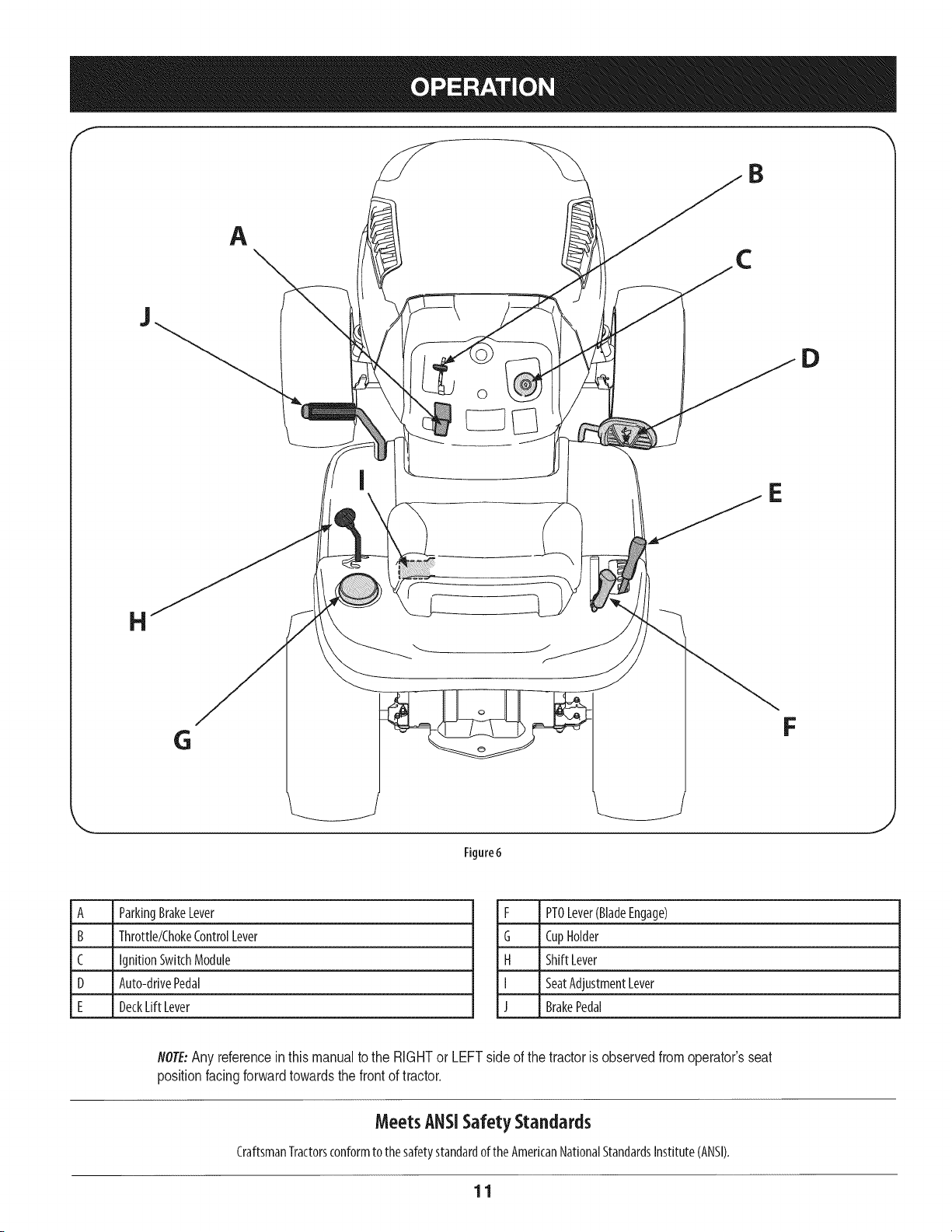
Rgure6
A ParkingBrakeLever
B Throttle/ChokeControlLever
C IgnitionSwitchModule
D Auto-drivePedal
E DeckLift Lever
F PTOLever(BladeEngage)
G CupHolder
H ShiftLever
I SeatAdjustmentLever
J BrakePedal
NOTE:Any referenceinthismanualto the RIGHTor LEFTside of the tractoris observedfromoperator'sseat
positionfacingforwardtowardsthe frontof tractor.
Meets ANSiSafetyStandards
CraftsmanTractorsconformto thesafetystandardoftheAmericanNationalStandardsInstitute(ANSI).
11
ParkingBrakeLever
Tosetthe parkingbrake:Fullydepressthe brakepedal.Movethe
parkingbrakeleverintotheparkingbrakeposition.Releasethe
brakepedalto allowthe parkingbraketo engage.
Toreleasethe parkingbrake:Depressthebrakepedalandthe
parkingbrakeleverwill moveoutof theparkingbrakepositionon
itsown.Theparkingbrakewill thenbe released.Releasethebrake
pedal.
NOTE:Theparkingbrakemustbesetif theoperatorleavestheseat
with the enginerunningortheenginewill automaticallyshut off.
Throttle/chokeControlLever
m
m
mmmmmmm
SLOW
Thethrottle/chokecontrolleverislocatedonthe
left sideof the tractor'sdashpanel.Thislever
controlsthespeedof theengineandwhenpushed
all thewayforward,thechokecontrolalso.When
setinagivenposition,thethrottle will maintaina
uniformenginespeed.
IMPORTANT:Whenoperating the tractor with the cutting
deck engaged, the throttle/choke control lever must
always be in the FAST (rabbit) position.
ignitionSwitch
Thekeyswitchmoduleisusedtostart andstoptheengine.Insert
keyintothekeyswitchmoduleandturn clockwiseto the START
position.Releasethe keyintothe normalmowingpositiononce
enginehasstarted.Theheadlightswill beactivatedautomatkally.
Tostoptheengine,turn the ignitionkeycounterclockwiseto the
STOPposition.
IMPORTANT:Priorto operatingthe
tractor,referto boththe "Safety
InterlockSystem"and"StartingThe
Engine"laterin thissectionof this
manualfordetailedinstructions
regardingtheIgnitionSwitch
Module.
Neverleavea running machineunattended.AlwaysdisengagePTO(Blade
EngageLever),moveshift [everintoneutralposition,set parking brake,
stopengineand removekeyto preventunintendedstarting.
SeatAdjustmentLever
Theseatadjustmentleverislocatedbelowthe front/left of theseat.Thelever
allowsforadjustmentof the foreandaft positionof theseat.Referto the Assembly
sectionof themanualformoredetailedinstructionsforadjustingthe seatposition.
Auto-drivepedal
Thedrivepedalislocatedontheright sideof the tractor,alongtherunningboard.
Depressthe drivepedalforwardandthetractorwi[[ moveinthedirectionthatthe
shift leverisengagedin.Tocausethe tractorto travelforward,whileata complete
stop,movethe shift [everinto the Forwardposition.Graduallysteponthedrive
pedalandthetractorwill beginto moveforward.TomoveinReverse,follow the
sameprocedureonlymovethe shift [everintothereverseposition.
Thegroundspeediscontrolledwith thedrivepedalThefurther forwardthat the
pedalis pivoted,thefasterthetractorwi[[ travel.Thepedalwill returnto its original
positionwhenit'snotdepressed.Referto theOperationsectionofthis manualfor
detailedinstructionsregardingthedrivepedal
IMPORTANT:Always set the parking brake when leaving the tractor
unattended.
DeckLift Lever
Foundon yourtractor'srightfender,the decklift leverisusedto
changetheheightof the cuttingdeck.Touse,movethe levertothe
left, thenplaceinthe notchbestsuitedforyourapplication.
PTO(Blade Engage)Lever
Foundon thetractor'srightfender,thePTO(bladeengage)lever
isusedto engagepowerto thecuttingdeckorother(separately
available)attachments.Tooperate,movetheleverall the way
forward.Movingthe leverall thewayrearwardintothe PTOOFF
positiondisengagespowerto thecutting deck/attachment.
NOTE:ThePTO (blade engage) lever must be in the
disengaged (PTO OFF) position when starting the engine.
CupHolder
Thetractor'scupholderislocatedon the fenderto theleft of the seat.
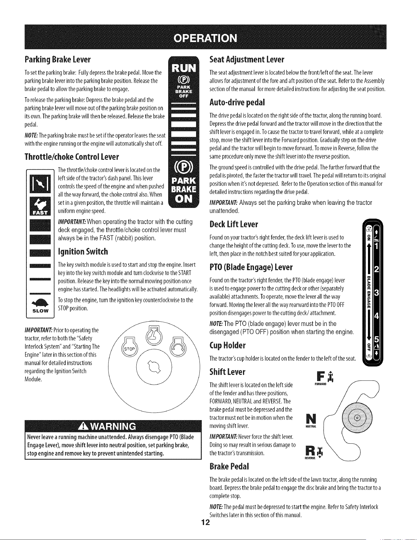
Shift Lover
Theshift leverislocatedon the left side
of thefenderandhasthreepositions,
FORWARD,NEUTRALandREVERSE.The
brakepedalmustbedepressedandthe
tractormustnotbeinmotionwhenthe
movingshift lever.
IMPORTANT:Neverforcethe shift lever.
Doingsomayresultinseriousdamageto
thetractor'stransmission.
BrakePedal
REVEP_E
Thebrakepedalislocatedonthe left sideofthelawntractor,alongthe running
board.Depressthe brakepedalto engagethe discbrakeandbringthetractorto a
completestop.
NOTE:Thepedalmustbedepressedtostart theengine.Referto SafetyInterlock
Switcheslaterin thissectionof thismanual.
12
Gasand Oil Fill-up
Oil
IMPORTAfl#Yourtractorisshippedwith motoroil intheengine.However,you
MUSTchecktheoillevelbeforeoperating.Becarefulnottooverfill.
Forinstructionsonhowto checktheengineoil,referto CheckingTheEngineOilin
theServiceandMaintenancesectionof thismanual.
Gasoline
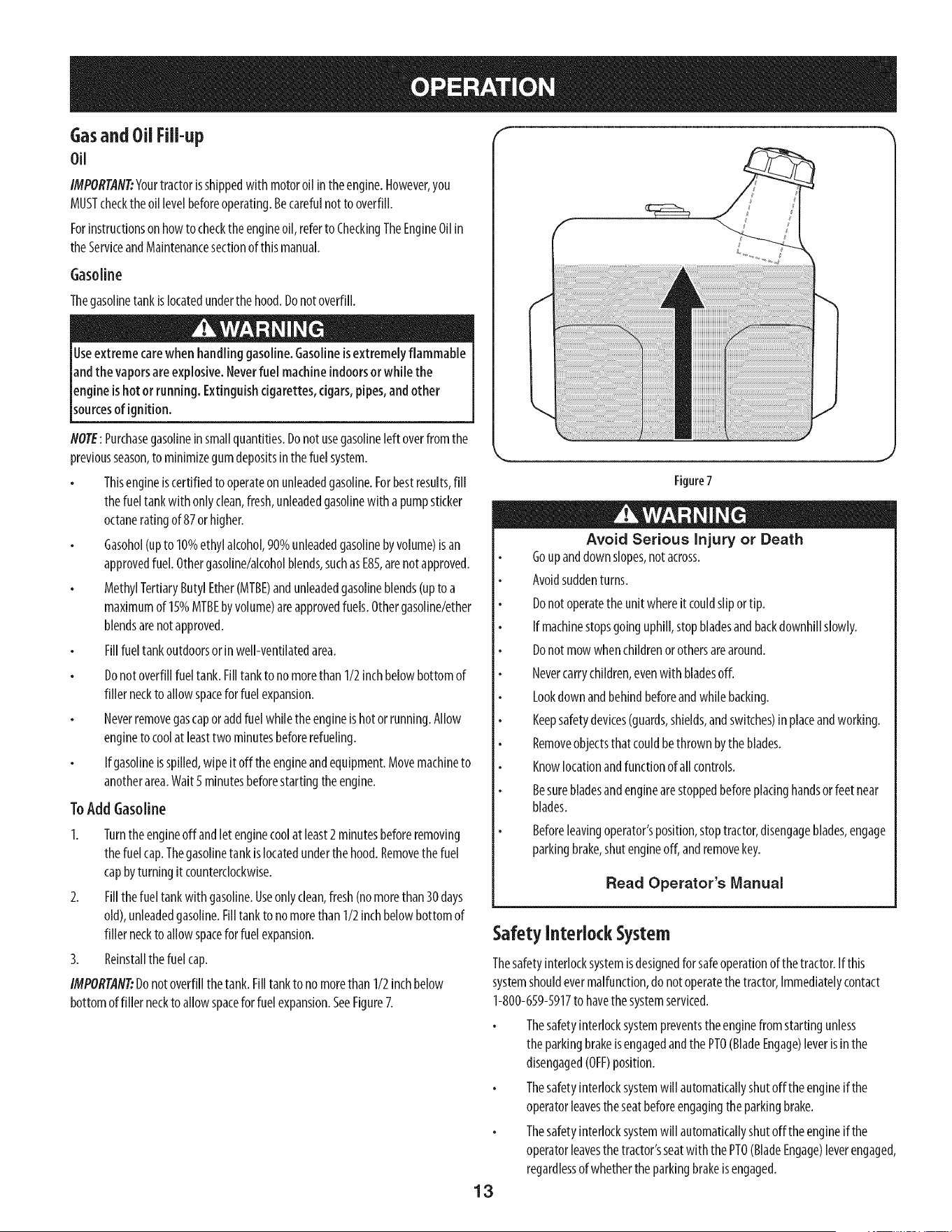
Thegasolinetank islocatedunderthe hood.Donotoverfill.
Useextreme carewhenhandling gasoline.Gasolineisextremelyflammable
andthe vaporsareexplosive.Neverfuel machineindoorsor while the
engineishot or running. Extinguishcigarettes,cigars,pipes,andother
sourcesof gn t on.
NOTE:Purchasegasolineinsmallquantities.Donotusegasolineleft overfromthe
previousseason,to minimizegumdepositsinthefuel system.
Thisengineiscertifiedto operateon unleadedgasoline.Forbestresults,fill
thefueltank with onlyclean,fresh,unleadedgasolinewith apumpsticker
octaneratingof 87orhigher.
Gasohol(upto 10%ethyl alcohol,90%unleadedgasolinebyvolume)isan
approvedfuel. Othergasoline/alcoholblends,suchasE85,arenotapproved.
MethylTertiaryButylEther(MTBE)andunleadedgasolineblends(upto a
maximumof 15%MTBEbyvolume)areapprovedfuels.Othergasoline/ether
blendsarenotapproved.
Fillfueltank outdoorsor inwell-ventilatedarea.
Donotoverfillfueltank.Filltankto nomorethan1/2inchbelowbottomof
filler neckto allowspaceforfuel expansion.
Neverremovegascaporaddfuelwhiletheengineis hotor running.Allow
engineto coolat leasttwo minutesbeforerefueling.
If gasolineisspilled,wipeit off theengineandequipment.Movemachineto
anotherarea.Wait5 minutesbeforestartingtheengine.
ToAdd Gasoline
1. Turnthe engineoff andletenginecoolat least2minutesbeforeremoving
thefuelcap.Thegasolinetank islocatedunderthehood.Removethefuel
capbyturningit counterclockwise.
2. Fillthefuel tankwith gasoline.Useonlyclean,fresh(nomorethan30days
old),unleadedgasoline.Filltank to nomorethan1/2 inchbelowbottomof
filler neckto allowspaceforfuel expansion.
3. Reinstallthefuel cap.
IMPORTAN_Donotoverfillthetank.Filltankto no morethan 1/2inchbelow
bottomoffiller neckto allowspaceforfuel expansion.SeeFigure7.
Figure7
Avoid Serious Injury or Death
Goupanddownslopes,notacross.
Avoidsuddenturns.
Donotoperatetheunitwhereit couldslipor tip.
If machinestopsgoinguphill,stopbladesandbackdownhillslowly.
Donotmowwhenchildrenor othersarearound.
Nevercarrychildren,evenwith bladesoff.
Lookdown andbehindbeforeandwhilebacking.
Keepsafetydevices(guards,shields,andswitches)inplaceandworking.
Removeobjectsthat couldbethrownbytheblades.
Knowlocationandfunctionof all controls.
Besurebladesandenginearestoppedbeforeplacinghandsor feet near
blades.
Beforeleavingoperator'sposition,stoptractor,disengageblades,engage
parkingbrake,shutengineoff,andremovekey.
Read Operator's Manual
Safety Interlock System
Thesafetyinterlocksystemisdesignedfor safeoperationofthe tractor.Ifthis
systemshouldevermalfunction,donot operatethetractor,Immediatelycontact
1-800-659-5917to havethe systemserviced.
Thesafetyinterlocksystempreventstheenginefrom startingunless
theparkingbrakeisengagedandthePTO(BladeEngage)leverisinthe
disengaged(OFF)position.
Thesafetyinterlocksystemwill automaticallyshutoff theengineifthe
operatorleavesthe seatbeforeengagingtheparkingbrake.
Thesafetyinterlocksystemwill automaticallyshutoff theengineifthe
operatorleavesthe tractor'sseatwiththe PTO(BladeEngage)leverengaged,
regardlessofwhethertheparkingbrakeisengaged.
13
Theenginewill automaticallyshutoff if thePTO(BladeEngage)leveris
movedintotheengaged(ON)positionwith the shift leverinReverse.
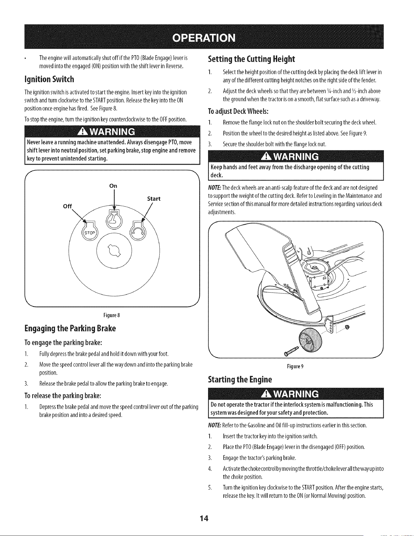
Ignition Switch
Theignitionswitchis activatedto startthe engine.Insertkeyinto the ignition
switchandturn clockwiseto the STARTposition.ReleasethekeyintotheON
positiononceenginehasfired. SeeFigure8.
Tostoptheengine,turn the ignitionkeycounterclockwiseto the OFFposition.
Neverleavea running machineunattended.AlwaysdisengagePTO,move
shift leverinto neutral position, set parkingbrake,stop engineand remove
keyto prevent unintended starting.
f
Setting the Cutting Height
1. Selectthe heightpositionof thecuttingdeckbyplacingthe decklift leverin
anyof thedifferentcutting heightnotcheson therightsideof the fender.
2. Adjustthe deckwheelssothatthey arebetweenl_-inchand1/2-inchabove
thegroundwhenthetractorison asmooth,flat surfacesuchasadriveway.
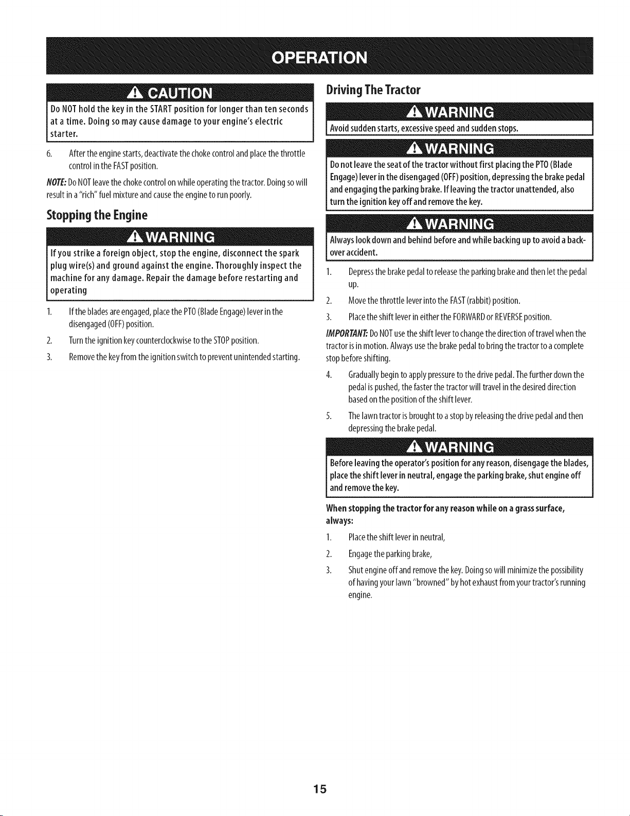
To adjust Deck Wheels:
1. Removethe flangelocknuton the shoulderbolt securingthe deckwheel.
2. Positionthe wheelto thedesiredheightaslistedabove.SeeFigure9.
3. Securetheshoulderbolt with the flangelocknut.
Keephandsandfeet awayfrom the dischargeopening of the cutting
deck.
off
On
Start
Figure8
Engaging the Parking Brake
To engage the parking brake:
1. Fullydepressthe brakepedalandholdit downwith yourfoot.
2. Movethespeedcontrolleverall the waydownandinto the parkingbrake
position.
3. Releasethebrakepedalto allowtheparkingbraketo engage.
Toreleasethe parkingbrake:
1. Depressthe brakepedalandmovethe speedcontrolleveroutof the parking
brakepositionandinto adesiredspeed.
NOTE:Thedeckwheelsareananti-scalpfeatureof thedeckandarenotdesigned
to supporttheweightof the cuttingdeck.Referto LevelingintheMaintenanceand
Servicesectionof thismanualformoredetailedinstructionsregardingvariousdeck
adjustments.
Starting the Engine
Figure9
J
Donot operatethe tractor if the interlocksystemismalfunctioning. This
systemwasdesignedfor your safetyand protection.
NOTE:Referto the GasolineandOilfill-up instructionsearlierinthissection.
1. Insertthetractorkeyintotheignitionswitch.
2. Placethe PTO(BladeEngage)leverinthedisengaged(OFF)position.
3. Engagethetractor'sparkingbrake.
4. ActivatethechokecontrolbymovingthethrotNe/chokeleverallthewayupinto
thechokeposition.
5. Turnthe ignitionkeyclockwiseto theSTARTposition.Afterthe enginestarts,
releasethekey.It will returnto theON(orNormalMowing)position.
14
DoNOThold the key inthe STARTpositionfor longerthan ten seconds
at a time. Doingsomay causedamageto your engine's electric
starter.
6. Afterthe enginestarts,deactivatethe chokecontrolandplacethethrottle
controlin theFASTposition.
NOTE:DoNOTleavethechokecontrolon while operatingthetractor.Doingsowill
resultin a"rich"fuel mixtureandcausetheengineto runpoorly.
Stopping the Engine
If you strike a foreign object, stop the engine, disconnectthe spark
plug wire(s) and ground against the engine. Thoroughlyinspect the
machine for any damage. Repair the damage before restarting and
operating
2.
3.
If thebladesareengaged,placethe PTO(BladeEngage)leverinthe
disengaged(OFF)position.
Turnthe ignitionkeycounterclockwiseto the STOPposition.
Removethe keyfrom theignitionswitchto preventunintendedstarting.
DrivingTheTractor
Avoidsuddenstarts,excessivespeedandsuddenstops.
Donot leavethe seatof the tractor without first placingthe PTO(Blade
Engage)leverin the disengaged(OFF)position, depressingthe brakepedal
andengaging the parkingbrake. If leavingthe tractor unattended,also
turn the ignition keyoffand removethe key.
Alwayslook down and behind beforeandwhile backingup to avoida back-
overaccident.
1. Depressthebrakepedalto releasethe parkingbrakeandthenlet the pedal
up.
2. Movethe throttle leverinto theFAST(rabbit)position.
3. Placetheshift leverineithertheFORWARDor REVERSEposition.
IMPORTAN_DoNOTusethe shift leverto changethe directionof travelwhenthe
tractorisin motion.Alwaysusethebrakepedalto bringthetractorto acomplete
stopbeforeshifting.
4. Graduallybeginto applypressureto the drivepedal.Thefurtherdownthe
pedalis pushed,thefasterthetractorwill travelin thedesireddirection
basedon the positionof theshift lever.
5. Thelawntractorisbroughtto astopbyreleasingthe drivepedalandthen
depressingthebrakepedal.
Beforeleavingthe operator'spositionfor any reason,disengagethe blades,
placethe shift lever in neutral, engagethe parking brake,shutengine off
and removethe key.
Whenstopping the tractor for anyreasonwhile on a grasssurface,
always:
Placethe shift leverinneutral,
I.
2.
3.
Engagetheparkingbrake,
Shutengineoffand removethe key.Doingsowill minimizethepossibility
of havingyourlawn"browned"byhotexhaustfromyourtractor'srunning
engine.
15
DrivingOnSlopes
Referto theSLOPEGAUGEintheSafetyInstructionssectionofthe manualto help
determineslopeswhereyoumayoperatethistractorsafely.
Donot mow on inclineswith a slope inexcessof 15degrees(ariseof
approximately2-112feet every 10feet). Thetractor couldoverturn and
causeseriousinjury.
Mowupanddownslopes,NEVERacross.
Exerciseextremecautionwhenchangingdirectiononslopes.
Watchfor holes,ruts,bumps,rocks,or otherhiddenobjects.Uneventerrain
couldoverturnthemachine.Tallgrasscanhideobstacles.
Avoidturnswhendrivingon aslope.Ifa turn mustbemade,turn downthe
slope.Turningup aslopegreatlyincreasesthechanceof aroll over.
Avoidstoppingwhendrivingupaslope.If it isnecessaryto stopwhile
drivingupaslope,startup smoothlyandcarefullyto reducethe possibility
of flippingthe tractoroverbackward.
Engagingthe Blades
Engagingthe PTO(BladeEngage)transferspowertothecuttingdeckorother
(separatelyavailable)attachments.Toengagetheblades,proceedasfollows:
1. Movethethrottle/chokecontrolleverto the FAST(rabbit)position.
2. Graspthe PTO(BladeEngage)leverandpivotit allthe wayforwardintothe
engaged(ON)position.
3. Keepthe throttleleverinthe FAST(rabbit)positionfor the mostefficientuse
of thecutting deckorother(separatelyavailable)attachments.
NOTE:Theenginewill automaticallyshutoff ifthe PTOisengagedwith theshift
leverinpositionforreversetravelwith theignitionkeyin theONposition.
Mulching
Amulchkit isavailableasanattachment.Mulchingisa processof recirculating
grassclippingsrepeatedlybeneaththe cuttingdeck.Theultra-fineclippingsare
thenforcedbackintothe lawnwheretheyactasanaturalfertilizer.
Amulchkit canbepurchasedthroughtheretaillocationinwhichyoupurchased
thistractor.Formoreinformation,simplycontactSearsat 1-800-659-5917.
Mowing
Tohelpavoid bladecontactor athrown object injury, keepbystanders,
helpers,children andpets at least 75;feet from the machinewhile it is in
operation. Stopmachineif anyoneentersthe area.
Thefollowing informationwill behelpfulwhenusingthe cuttingdeckwith your
tractor:
Planyour mowing pattern to avoiddischargeof materialstoward roads,
sidewalks,bystandersandthe like.Also,avoiddischargingmaterial against
awall or obstructionwhichmay causedischargedmaterialto ricochet back
toward the operator.
Donotmowat highgroundspeed,especiallyira mulchkitorgrasscollector
isinstalled.
Forbestresultsit isrecommendedthatthe first two lapsbe cutwith the
dischargethrowntowardsthecenter.Afterthe first two laps,reversethe
directionto throwthe dischargeto theoutsideforthe balanceof cutting.
Thiswill giveabetterappearanceto thelawn.
Donotcutthe grasstooshort.Shortgrassinvitesweedgrowth andyellows
quicklyindryweather.
Mowingshouldalwaysbedonewith theengineatfull throttle.
Underheavierconditionsit maybenecessaryto gobackoverthecutareaa
secondtimeto getacleancut.
DoNOTattemptto mowheavybrushandweedsandextremelytall grass.
Yourtractorisdesignedto mowlawns,NOTclearbrush.
Keepthe bladessharpandreplacethe bladeswhen worn.Referto Cutting
Bladesin the Servicesectionof thismanualforproperbladesharpening
instructions.
Headlights
ThelampsareONwheneverthe tractor'sengineisrunning.
Thelampsturn OFFwhentheignitionkeyis movedto theSTOPposition.
Usingthe DeckLift Lever
Toraisethe cuttingdeck,movethedecklift leverto the left,then placeit in the
notchbestsuitedfor yourapplication.Referto SettingTheCuttingHeightearlierin
thissection.
16
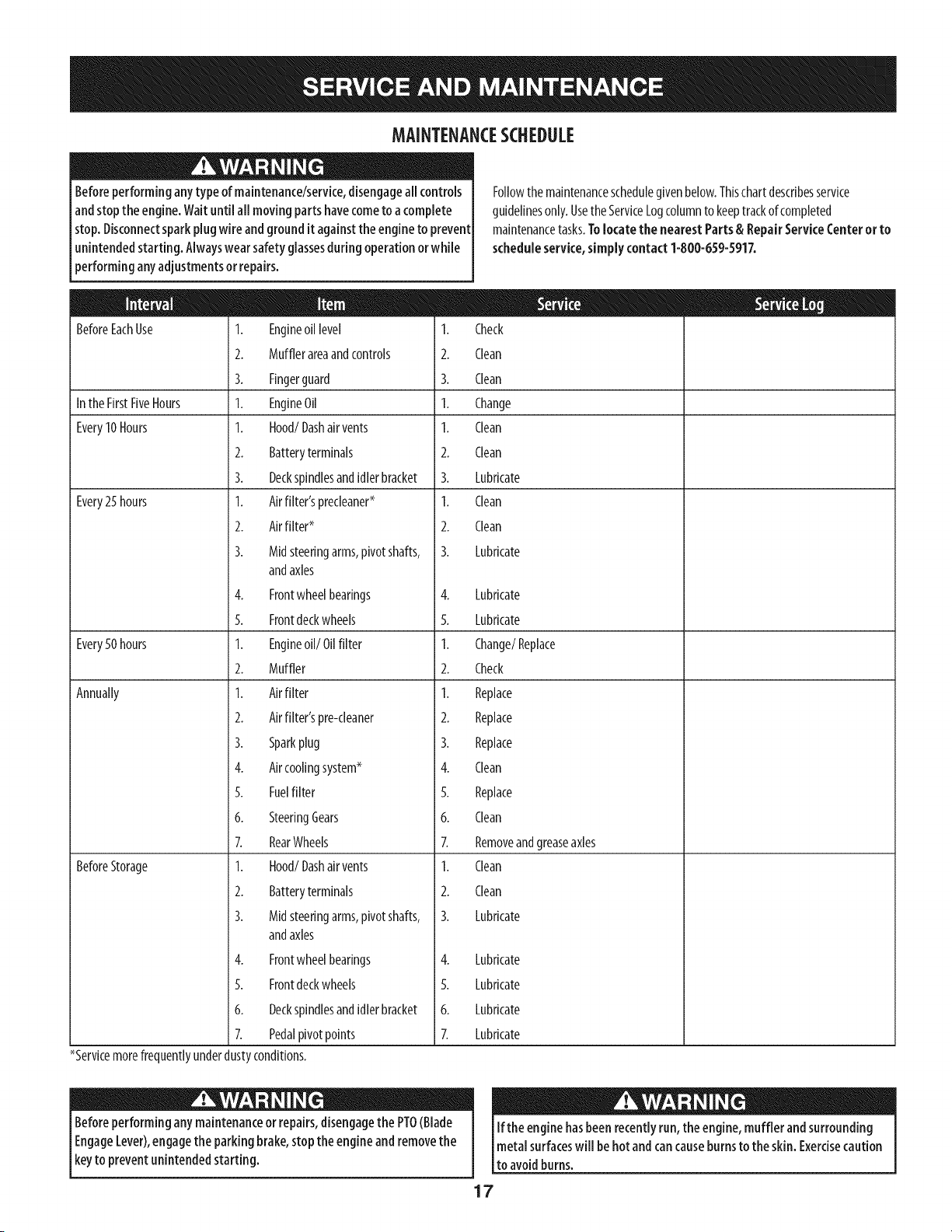
MAINTENANCESCHEDULE
Beforeperforminganytype of maintenance/service,disengageall controls
andstopthe engine.Waituntil all movingpartshavecometo a complete
stop.Disconnectsparkplugwire andgroundit againstthe engineto prevent
unintendedstarting. Alwayswearsafety glassesduring operationorwhile
performing anyadjustments or repairs.
BeforeEachUse 1. Engineoil level 1.
2. Mufflerareaandcontrols 2.
3. Fingerguard 3.
Inthe FirstFiveHours 1. EngineOil 1.
Every10Hours I. Hood/Dashair vents I.
2. Batteryterminals 2.
3. Deckspindlesandidlerbracket 3.
Every25 hours 1. Airfilter'sprecleaner* 1.
2. Airfilter* 2.
3. Midsteeringarms,pivotshafts, 3.
andaxles
4. Frontwheelbearings 4.
5. Frontdeckwheels 5.
Every50 hours 1. Engineoil/Oil filter 1.
2. Muffler 2.
Annually 1. Airfilter 1.
2. Airfilter'spre-cleaner 2.
3. Sparkplug 3.
4. Aircoolingsystem* 4.
5. Fuelfilter 5.
6. SteeringGears 6.
7. RearWheels 7.
BeforeStorage 1. Hood/Dashair vents 1.
2. Batteryterminals 2.
3. Midsteeringarms,pivotshafts, 3.
andaxles
4. Frontwheelbearings
5. Frontdeckwheels
6. Deckspindlesandidlerbracket
7. Pedalpivotpoints
*Servicemorefrequentlyunderdustyconditions.
Followthe maintenanceschedulegivenbelow.Thischartdescribesservice
guidelinesonly.UsetheServiceLogcolumnto keeptrackofcompleted
maintenancetasks.Tolocate the nearestParts & RepairServiceCenter or to
scheduleservice,simply contact1-800-659-5917.
Check
Clean
Clean
Change
Clean
Clean
Lubricate
Clean
Clean
Lubricate
Lubricate
Lubricate
Change/Replace
Check
Replace
Replace
Replace
Clean
Replace
Clean
Removeandgreaseaxles
Clean
Clean
Lubricate
4. Lubricate
5. Lubricate
6. Lubricate
7. Lubricate
Beforeperformingany maintenanceor repairs,disengagethe PTO(Blade
EngageLever),engagethe parkingbrake,stopthe engine andremovethe
keyto prevent unintendedstarting.
If the engine hasbeen recentlyrun,the engine,muffler and surrounding
metal surfaceswill behot andcancauseburnsto the skin. Exercisecaution
to avoidburns.
17
Engine Maintenance
Checkingthe Engine Oil
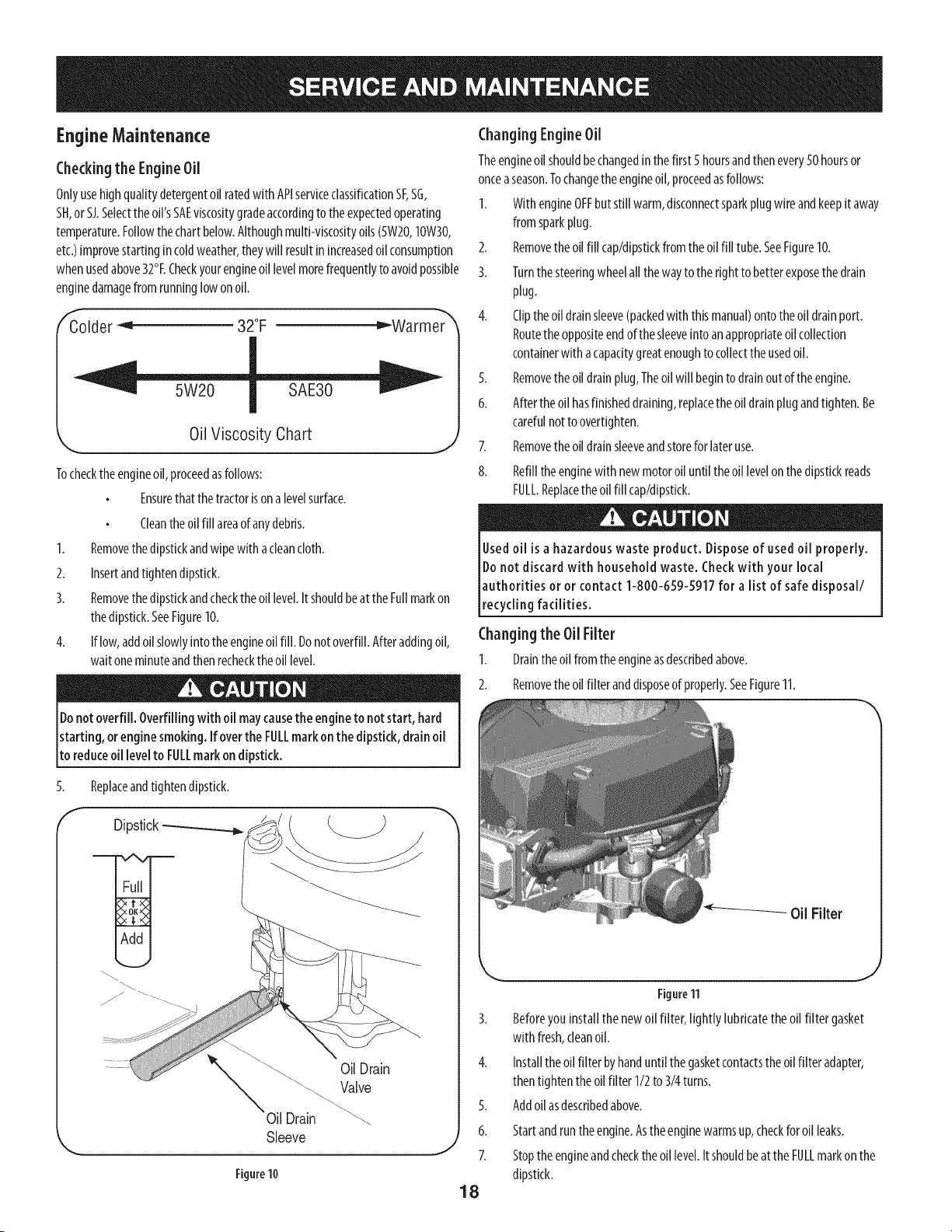
Onlyusehighqualitydetergentoilratedwith APIserviceclassificationSF,SG,
SH,or SJ.Selecttheoil'sSAEviscositygradeaccordingto the expectedoperating
temperature.Followthechartbelow.Althoughmulti-viscosityoils (5W20,10W30,
etc.)improvestartingin coldweather,theywill resultinincreasedoil consumption
whenusedabove32°ECheckyourengineoillevelmorefrequentlyto avoidpossible
enginedamagefrom runninglowon oil.
f
Colder _ 32°F _Warmer
Oil Viscosity Chart
Tocheckthe engineoil,proceedasfollows:
Ensurethatthetractorison alevelsurface.
J
Cleantheoil fill areaof anydebris.
1. Removethe dipstickandwipewith acleancloth.
2. Insertandtightendipstick.
3. Removethe dipstickandchecktheoil level.Itshouldbeat theFullmarkon
thedipstick.SeeFigure10.
4. If low,addoil slowlyinto the engineoilfill. Donotoverfill.Afteraddingoil,
waitoneminuteandthenrechecktheoil level.
Donotoverfill. Overfilling with oil maycausethe engineto not start, hard
starting, orengine smoking. If overthe FULLmark on the dipstick,drain oil
to reduceoil levelto FULLmark on dipstick.
Replaceandtightendipstick.
5.
f
OilDrain
Valve
Oil Drain
Sleeve
Figure 10
ChangingEngineOil
Theengineoil shouldbechangedin thefirst 5hoursandthenevery50 hoursor
onceaseason.Tochangetheengineoil,proceedasfollows:
I. With engineOFFbutstill warm,disconnectsparkplugwire andkeepit away
from sparkplug.
2. Removethe oil fill cap/dipstkkfromthe oil fill tube.SeeFigure10.
3. Turnthe steeringwheelall the wayto the rightto betterexposethe drain
plug.
4. Cliptheoil drainsleeve(packedwith thismanual)ontotheoil drainport.
Routethe oppositeendofthe sleeveinto anappropriateoil collection
containerwith acapacitygreatenoughto collecttheusedoil.
5. Removethe oil drainplug,Theoil will beginto drainout of theengine.
6. Afterthe oil hasfinisheddraining,replacethe oil drainplugandtighten.Be
carefulnotto overtighten.
Removethe oil drainsleeveandstoreforlateruse.7.
8.
Refillthe enginewith newmotoroil untilthe oil levelonthedipstickreads
FULL.Replacetheoil fill cap/dipstick.
Usedoil is a hazardouswaste product. Disposeof used oil properly.
Donot discard with household waste. Checkwith your local
authorities or or contact 1-800-659-5917 for a list of safe disposal/
recycling facilities.
Changingthe Oil Filter
I. Draintheoil fromthe engineasdescribedabove.
2. Removethe oil filteranddisposeof properly.SeeFigure11.
Figure11
3. Beforeyou installthenewoil filter, lightly lubricatetheoil filter gasket
with fresh,cleanoil.
4. Installtheoil filter byhanduntil the gasketcontactsthe oilfilteradapter,
thentighten theoil filter 1/2to 3/4turns.
5. Addoilasdescribedabove.
6. Startandruntheengine.Astheenginewarmsup,checkforoil leaks.
7. Stoptheengineandchecktheoil level.Itshouldbeat theFULLmarkon the
dipstick.
18
Fuel Filter
Gasolineanditsvapors areextremely flammable andexplosive.Fireor
explosioncancausesevereburnsordeath.
Keepgasolineawayfrom sparks,openflames,pilot lights,heat,andother
ignitionsources.
Checkfuellines,tank,cap,andfittingsfrequentlyforcracksor leaks.Replace
if necessary.
Beforereplacingthe fuelfilter, drainthe fuel tank aspertheinstructions
below.
Donotdrainfuel whentheengineishot.Allowtheengineadequatetime to
cool.Drainfuelinto anapprovedcontaineroutdoors,awayfromopenflame.
Drainanylargevolumeoffuel from thetankbydisconnectingthe fuel line
fromthe in-linefuelfilter nearthe engine.
Removethe fuel linefromthe In-lineside(sidetowardsthefuel tank)of the
fuelfilter.
Replacementpartsmustbethesameandinstalledinthe samepositionas
theoriginalparts.
If fuelspills,wait until it evaporatesbeforestartingengine.
Beforereplacingthe fuelfilter, drainthe fuel tank.Otherwise,fuelcanleak
outandcauseafireorexplosion.
To Drain the fuel:
1. Locatethefuelfilter,whichisroutedonthe left sideof theenginebetween
thefueltankandthecarburetor,andmaybeattachedtothe enginewith atie
strap.Cutthetie strap,if present,thenpinchthe in-lineclamponthefuel filter
withapairof pliers,slidetheclampupthefuelline.Pullthefuel linefreefrom
thefilterandplacetheopenendof thelineintoanapprovedcontainerto drain
thefuel.
To change the fuel filter:
1. Usepliersto squeezethetabson the otherclamp(theout-linesideof the
fuelfilter), thenslidetheclampawayfromthe fuelfilter. Twistandpullthe
fuel lineoff of thefuel filter.SeeFigure12.
Clamp
Fuel
Line
Tab
Figure12
2. Checkthefuellinesforcracksorleaks.Replaceif necessary.
3. Replacethefuel filterwith an originalequipmentreplacementfilter. Call
1-800-659-5917to purchasethe originalequipmentreplacementfilter.
4. Securethefuel lineswiththe clamps.
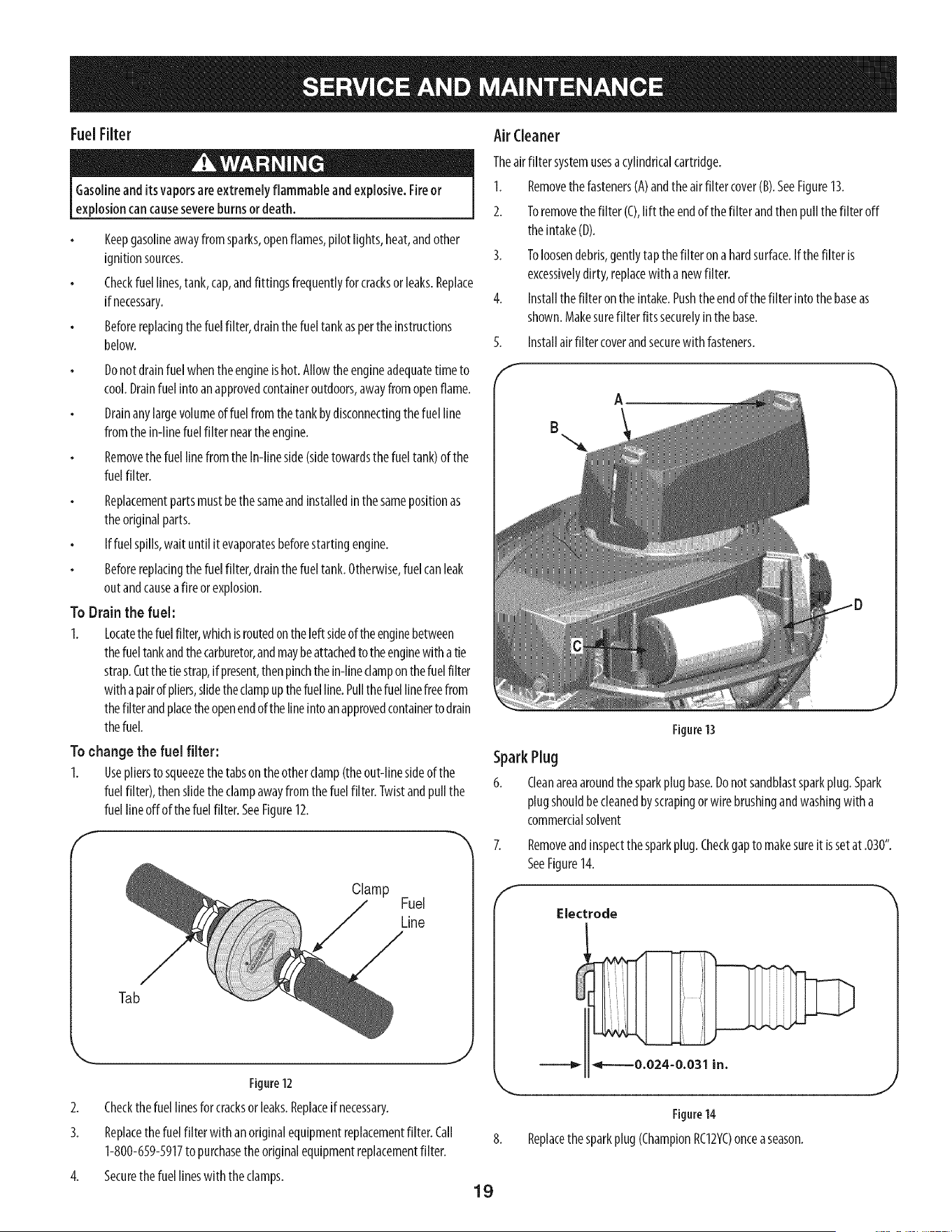
Air (:leaner
Theairfilter systemusesacylindricalcartridge.
1. Removethe fastenersCA)andtheair filtercover(B).SeeFigure13.
2. Toremovethe filter (C),lift theendof thefilter andthenpullthefilter off
theintake(D).
3. Toloosendebris,gentlytapthe filter onahardsurface.If the filter is
excessivelydirty, replacewith a newfilter.
4. Installthe filteronthe intake.Pushtheendof thefilter into thebaseas
shown.Makesurefilter fitssecurelyin thebase.
Installairfilter coverandsecurewith fasteners.5.
f
SparkPlug
6.
A
Figure 13
Cleanareaaroundthesparkplugbase.Donotsandblastsparkplug.Spark
plugshouldbecleanedbyscrapingor wire brushingandwashingwith a
commercialsolvent
f
Removeandinspectthesparkplug.Checkgapto makesureit issetat .030".
SeeFigure14.
Electrode
Figure14
Replacethesparkplug(ChampionRC12YC)onceaseason.
J
19
Muffler
Temperatureof muffler andnearbyengine areasmayexceed150° F(65°Q.
Avoidcontactwith theseareas.
Inspectmufflerperiodically,andreplaceif necessary.Replacementparts
forthemufflermustbethesameandinstalledinthesamepositionasthe
originalparts.
CleanEngine
Dailyor beforeeveryuse,deangrass,chaffor accumulateddebrisfrom
engine.Keeplinkage,spring,andcontrolsdean.
Keepareaaroundandbehindmufflerfreeof anycombustibledebris.
Keepingenginecleanaflowsair movementaroundengine.
Enginepartsshouldbekeptcleanto reducethe riskof overheatingand
ignitionofaccumulateddebris.
Donotusewater to dean engineparts. Watercouldcontaminatefuel
system.Usea brushor dry cloth.
CarburetorAdjustment
Thecarburetoronthisengineis notadjustable.
Lubrication
lubricating, repairing, orinspecting,alwaysdisengagePTO(Blade [
Before
EngageLever),moveshift leverinto neutral position,set parking brake,stopI
eng ne andremovekeyto prevent un ntendedstart rig. I
J
Pivot Points& Linkage
Lubricateallthe pivot pointsonthedrivesystem,parkingbrakeandlift linkageat
leastonceaseasonwith light oil.
RearWheels
Therearwheelsshouldberemovedfromtheaxlesonceaseason.Lubricatethe
axlesandtherimswell with anall-purposegreasebeforere-installingthem.
Front Axles
Eachendof thetractor'sfrontpivotbarmaybeequippedwith agreasefitting.
Lubricatewith agreasegunafterevery25 hoursof tractoroperation.
Battery
Thebatteryissealedandis maintenance-free.Acidlevelscannotbechecked.
Alwayskeepthe batterycablesandterminalsdeanandfreeofcorrosive
build-up.
Aftercleaningthe batteryandterminals,applya lightcoatof petroleumjelly
orgreaseto bothterminals.
Alwayskeepthe rubberbootpositionedoverthe positiveterminalto prevent
shorting.
IM PORTANT: If removingthebatteryforanyreason,disconnectthe NEGATIVE
(Black)wirefromitsterminalfirst,followedbythePOSITIVE(Red)wire.When
re-installingthebattery,alwaysconnectthePOSITIVE(Red)wire to its terminal
first, followedbytheNEGATIVE(Black)wire. Becertainthat the wiresareconnected
to thecorrectterminals;reversingthem couNchangethepolarityandresultin
damageto yourengine'salternatingsystem.
Cleaning Battery
Cleanthebatteryby removingitfrom the tractorandwashingwith abakingsoda
andwatersolution.If necessary,scrapethe batteryterminalswith awire brushto
removedeposits.Coatterminalsandexposedwiringwith greaseor petroleumjelly
to preventcorrosion.
Battery Failures
Somecommoncausesfor batteryfailureare:
Incorrectinitialactivation
Overcharging
Freezing
Undercharging
Corrodedconnections
ThesefailuresareNOTcoveredbyyourtractor'swarranty.
Cleaning the EngineAnd Deck
Anyfueloroil spilledon themachineshouldbewipedoff promptly.DoNOTallow
debristo accumulatearoundthe coolingfinsof the engineoron anyotherpart of
themachine.
IMPORTANT: Theuseofa pressurewasherto cleanyourtractorisNOT
recommended.It maycausedamageto electricalcomponents,spindles,pulleys,
bearingsortheengine.
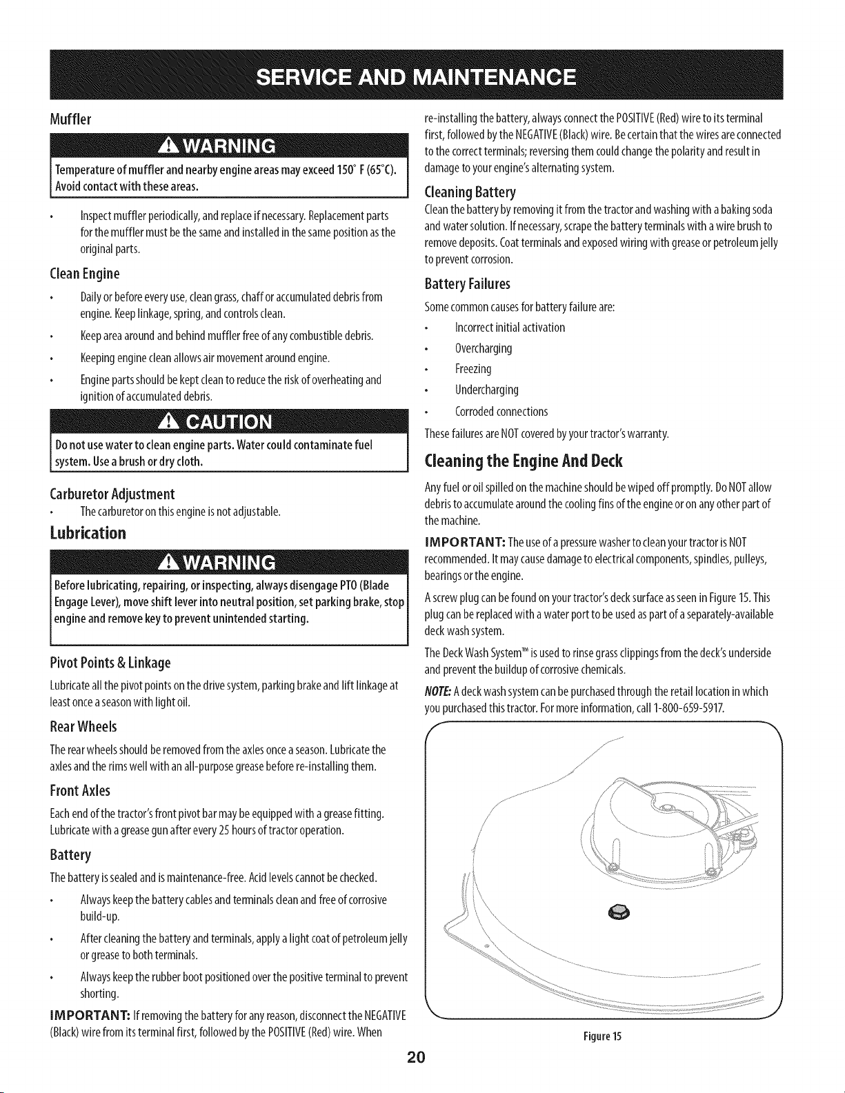
Ascrewplugcanbefoundonyourtractor'sdecksurfaceasseenin Figure15.This
plugcanbereplacedwith a waterportto beusedaspartof aseparately-available
deckwashsystem.
TheDeckWashSystemTM isusedto rinsegrassclippingsfrom the deck'sunderside
andpreventthebuildupof corrosivechemicals.
NOTE:Adeckwashsystemcanbepurchasedthroughtheretaillocationinwhich
youpurchasedthistractor.Formoreinformation,carl1-800-659-5917.
/
Figure15
2O
Adjustments SidetoSide
Neverattempt to makeany adjustmentswhile the engine isrunning,except
where specifiedin the operator'smanual.
Leveling the Deck
NOTE:Checkthetractor'stirepressurebeforeperforminganydeckleveling
adjustments.RefertoTiresin theServicesectionofthismanualformore
informationregardingtirepressure.
FrontToRear
Thefront ofthe cuttingdeckissupportedbyastabilizerbarthatcanbeadjustedto
levelthedeckfromfront to rear.Thefront of thedeckshouldbebetween1A-inch
and_8-inchlowerthanthe rearof the deck.Adjustif necessaryasfollows:
1. With thetractorparkedona firm, levelsurface,placetheleverforlifting the
platformonthe secondto the top notch(secondhighestposition)androtate
thebladeascloseaspossibleto the dischargechannelthat isparalleltothe
tractor.
2. Measurethe distancefrom the front ofthe bladetip to the groundandthe
rearofthe bladetip to the ground.Thefirst measurementtakenshould
bebetweenlg,,and3/8"lessthanthe secondmeasurement.Determine
theapproximatedistancenecessaryfor properadjustmentandproceed,if
necessary,to the nextstep.
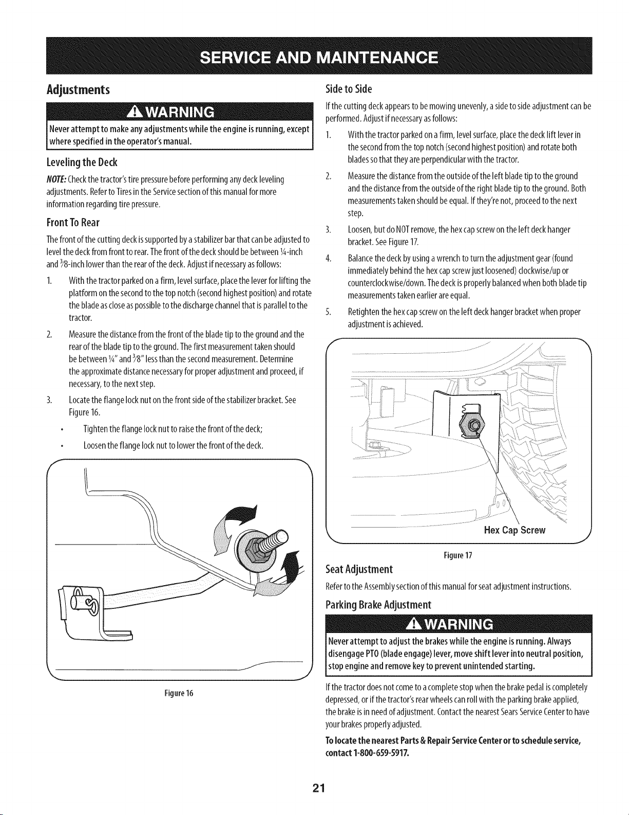
3. Locatetheflangelocknuton the front sideofthestabilizerbracket.See
Figure16.
Tightenthe flangelocknutto raisethe front of thedeck;
Loosentheflangelocknutto lowerthefront of thedeck.
f
J
Figure16
Ifthe cuttingdeckappearsto be mowingunevenly,asideto sideadjustmentcanbe
performed.Adjustifnecessaryasfollows:
1. With the tractorparkedonafirm, levelsurface,placethedecklift leverin
thesecondfrom the topnotch(secondhighestposition)androtateboth
bladessothat theyareperpendicularwith thetractor.
2. Measurethedistancefromthe outsideof the left bladetip to theground
andthedistancefromtheoutsideof theright bladetip to the ground.Both
measurementstakenshouldbeequal.Ifthey'renot,proceedto the next
step.
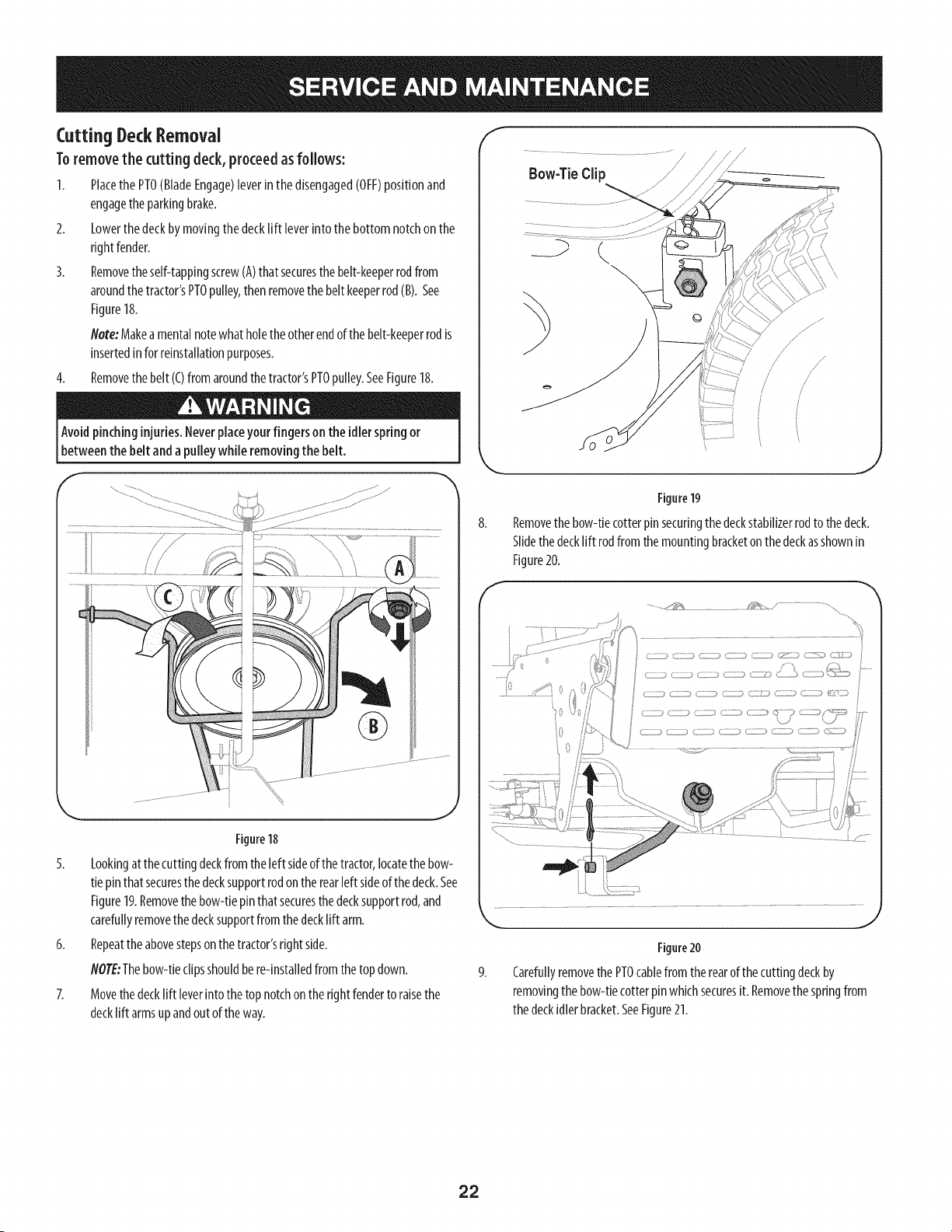
3. Loosen,but doNOTremove,thehexcapscrewontheleft deckhanger
bracket.SeeFigure17.
4. Balancethedeckbyusinga wrenchto turn theadjustmentgear(found
immediatelybehindthehexcapscrewjust loosened)clockwise/upor
counterclockwise/down.Thedeckisproperlybalancedwhenbothbladetip
measurementstakenearlierareequal.
5. Retightenthehexcapscrewon theleft deckhangerbracketwhenproper
adjustmentisachieved.
Hex Cap Screw
Figure17
SeatAdjustment
Referto theAssemblysectionof thismanualforseatadjustmentinstructions.
Parking BrakeAdjustment
Neverattempt to adjust the brakeswhile the engineisrunning. Always
disengagePTO(blade engage)lever,moveshift leverintoneutral position,
stopengine and removekeyto preventunintended starting.
Ifthe tractordoesnotcometo acompletestopwhenthebrakepedaliscompletely
depressed,or ifthe tractor'srearwheelscanroll with the parkingbrakeapplied,
thebrakeis in needof adjustment.Contactthe nearestSearsServiceCenterto have
yourbrakesproperlyadjusted.
Tolocatethe nearest Parts& RepairService(enter or to scheduleservice,
contact 1-800-659-5917.
21
Cutting Deck Removal
To remove the cutting deck, proceed as follows:
1. Placethe PTO(BladeEngage)leverinthe disengaged(OFF)positionand
engagethe parkingbrake.
2. Lowerthe deckbymovingthe decklift leverintothe bottomnotchon the
rightfender.
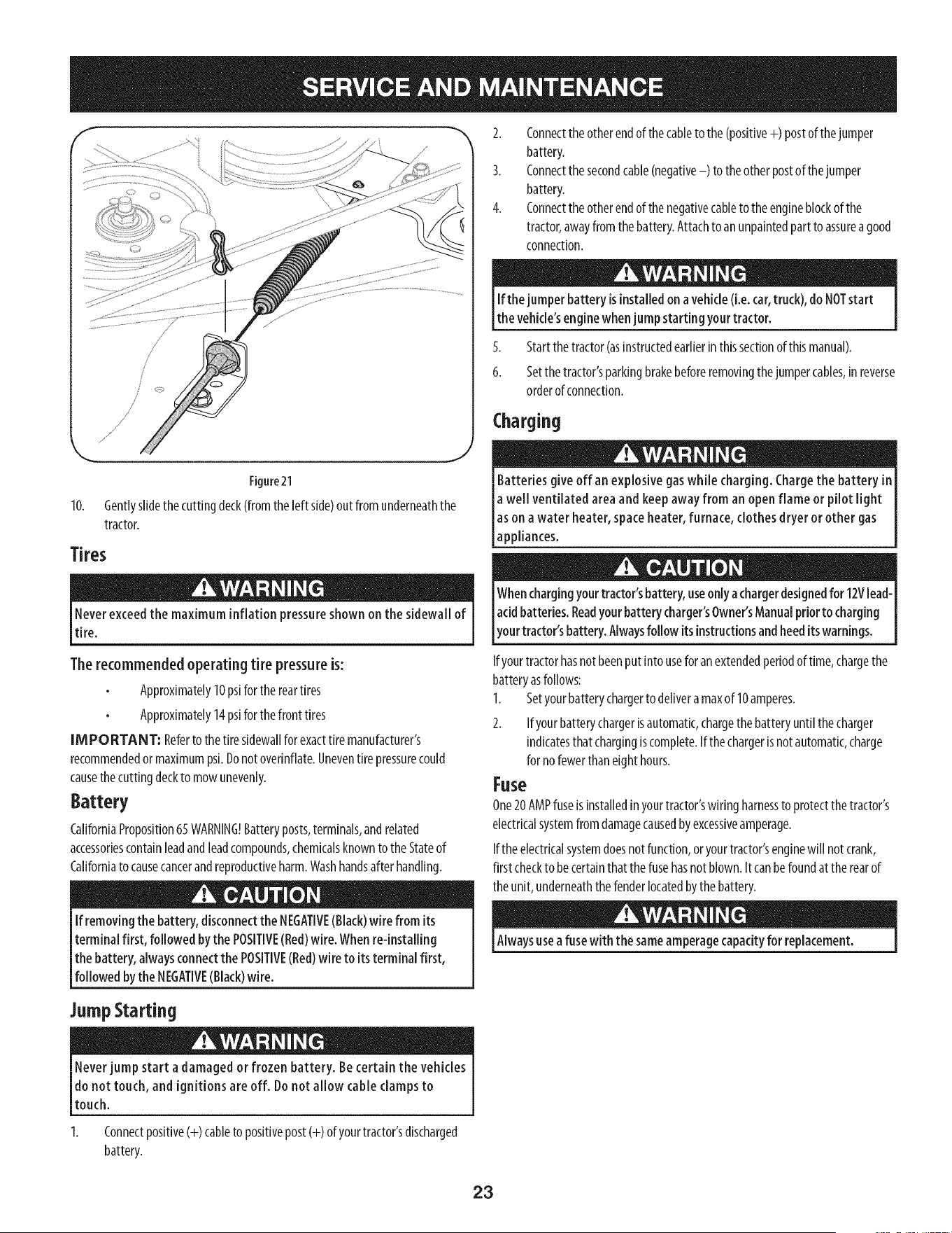
3. Removethe self-tappingscrew(A)thatsecuresthe belt-keeperrodfrom
aroundthetractor'sPTOpulley,then removethebelt keeperrod(B).See
Figure18.
Note:Makeamentalnotewhatholethe otherendof thebelt-keeperrodis
insertedinfor reinstallationpurposes.
4. Removethe belt (C)from aroundthetractor'sPTOpulley.SeeFigure18.
Avoidpinching injuries.Neverplaceyour fingers on the idlerspring or
betweenthe belt anda pulley while removing the belt.
..... .........................! ......
Figure18
5. Lookingat the cuttingdeckfrom the left sideofthetractor,locatethe bow-
tie pinthatsecuresthedecksupportrodonthe rearleft sideof thedeck.See
Figure19.Removethe bow-tiepinthat securesthedecksupportrod,and
carefullyremovethe decksupportfromthedecklift arm.
6. Repeatthe abovestepsonthetractor'srightside.
NOTE:Thebow-tieclipsshouldbe re-installedfrom thetop down.
7. Movethedecklift leverintothetop notchon therightfenderto raisethe
decklift armsupandoutof the way.
Bow-TieClip
///
f
\
,J
Figure19
Removethe bow-tiecotterpinsecuringthedeckstabilizerrodto thedeck.
Slidethedecklift rodfrom themountingbracketonthedeckasshownin
Figure20.
..................._,@_.................................._,: _ / .......................................
....../
i ..................4_1 0
J
Figure20
9. Carefullyremovethe PTOcablefrom the rearof the cuttingdeckby
removingthe bow-tiecotterpinwhichsecuresit. Removethe springfrom
thedeckidler bracket.SeeFigure21.
22
//
Figure21
10. Gentlyslidethecuttingdeck(fromthe left side)out from underneaththe
tractor,
Tires
Neverexceedthe maximum inflation pressureshown on the sidewall of
tire.
Therecommendedoperating tire pressureis:
Approximately10psifor the reartires
Approximately14psifor thefront tires
IMPORTANT: Referto the tiresidewallforexacttiremanufacturer's
recommendedor maximumpsi.Donotoverinflate.Uneventire pressurecould
causethe cuttingdeckto mowunevenly.
Battery
CaliforniaProposition65WARNING!Batteryposts,terminals,andrelated
accessoriescontainleadandleadcompounds,chemicalsknownto theStateof
Californiato causecancerandreproductiveharm.Washhandsafter handling.
If removingthe battery, disconnectthe NEGATIVE(Black)wire from its
terminal first, followed by the POSITIVE(Red)wire.Whenre-installing
the battery, alwaysconnectthe POSITIVE(Red)wire to itsterminal first,
followed bythe NEGATIVE(Black)wire.
2. Connecttheotherendof the cableto the (positive+) postof thejumper
battery.
3. Connectthesecondcable(negative-) to theotherpostof thejumper
battery.
4. Connectthe otherendof thenegativecableto theengineblockofthe
tractor,awayfrom the battery.Attachto anunpaintedpartto assureagood
connection.
If thejumperbattery isinstalledon avehicle(i.e. car,truck),doNOTstart
the vehicle'senginewhen jump starting your tractor.
5. Startthe tractor(asinstructedearlierinthissectionof thismanual).
6. Setthetractor'sparkingbrakebeforeremovingthejumpercables,in reverse
orderof connection.
Charging
give off an explosive gaswhile charging. Chargethe battery in [
Batteries
a well ventilated area and keepaway from an open flame or pilot light [
as on a water heater, spaceheater, furnace, clothes dryer or other gas [
lapp antes. J
Whenchargingyourtractor'sbattery, useonlyachargerdesignedfor 12Vlead-
[acidbatteries.Readyourbatterycharger'sOwner'sManualprior to charging
[your tractor's battery.Alwaysfollow itsinstructionsandheedits warnings.
Ifyourtractorhasnot beenputinto useforanextendedperiodof time,chargethe
batteryasfollows:
1. Setyourbatterychargerto delivera maxof 10amperes.
2. Ifyourbatterychargerisautomatic,chargethebatteryuntilthecharger
indicatesthatchargingiscomplete.If thechargerisnotautomatic,charge
for nofewerthaneighthours.
Fuse
One20AMPfuseis installedinyourtractor'swiringharnessto protectthetractor's
electricalsystemfromdamagecausedbyexcessiveamperage.
Ifthe electricalsystemdoesnotfunction,or yourtractor'senginewill notcrank,
first checkto becertainthatthe fusehasnotblown.It canbefoundat therearof
theunit, underneaththe fenderlocatedbythe battery.
Alwaysusea fusewith thesameamperagecapacityfor replacement.
JumpStarting
Neverjump start a damaged or frozen battery. Becertain the vehicles
do not touch, and ignitions are off. Do not allow cable clamps to
touch.
Connectpositive(+)cableto positivepost(+) ofyourtractor'sdischarged
battery.
23
CuttingBlades
Shutthe engineoff andremoveignitionkeybeforeremoving the cutting
blade(s)for sharpeningorreplacement.Protectyourhandsbyusingheavy
[g oveswhengraspng the bade.
Periodicallyinspectthe bladeand/or spindlefor cracksordamage,
[especiallyafter you'vestrucka foreign object. Donotoperate themachine
[until damagedcomponentsarereplaced.
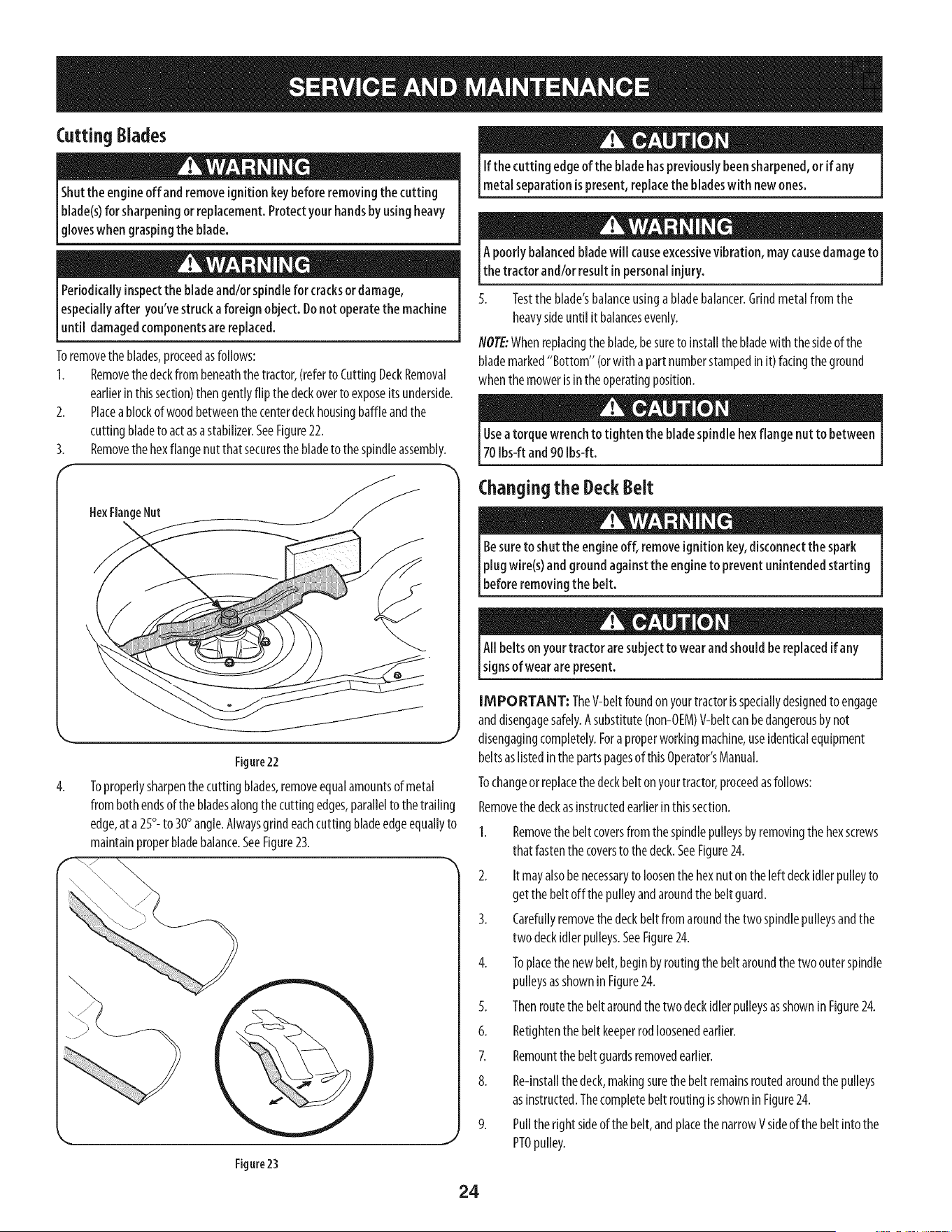
Toremovetheblades,proceedasfollows:
1. Removethe deckfrom beneaththetractor,(referto CuttingDeckRemoval
earlierin thissection)thengentlyflip the deckoverto exposeits underside.
2. Placeablockof woodbetweenthe centerdeckhousingbaffleandthe
cuttingbladeto actasastabilizer.SeeFigure22.
3. Removethe hexflangenutthatsecuresthe bladeto thespindleassembly.
HexFlangeNut
4.
Figure22
\
Toproperlysharpenthe cutting blades,removeequalamountsof metal
from bothendsofthe bladesalongthecuttingedges,parallelto the trailing
edge,ata 25°- to 30° angle.Alwaysgrindeachcuttingbladeedgeequallyto
maintainproperbladebalance.SeeFigure23.
Figure23
If the cutting edge of the bladehaspreviously beensharpened,or if any
metalseparationispresent,replacethe bladeswith newones.
A poorly balancedbladewill causeexcessivevibration, maycausedamageto
the tractor and/or resultin personalinjury.
5. Testtheblade'sbalanceusingabladebalancer.Grindmetalfrom the
heavysideuntil it balancesevenly.
NOTE:Whenreplacingthe blade,besureto installthebladewith the sideof the
blademarked"Bottom" (orwitha part numberstampedinit) facingtheground
whenthemowerisin theoperatingposition.
Useatorque wrenchto tighten the bladespindlehexflange nut to between
70Ibs-ft and 90 Ibs-ft.
Changing the DeckBelt
Besureto shutthe engineoff, removeignitionkey,disconnectthe spark
plugwire(s)and groundagainst the engineto prevent unintendedstarting
beforeremovingthe belt.
All belts on yourtractor aresubjectto wear andshouldbe replacedif any
signsof wearare present.
IMPORTANT: TheV-beltfoundon yourtractorisspeciallydesignedto engage
anddisengagesafely.Asubstitute(non-OEM)V-beltcanbedangerousbynot
disengagingcompletely.Fora properworkingmachine,useidenticalequipment
beltsaslistedinthe partspagesof thisOperator'sManual.
Tochangeorreplacethedeckbelt onyourtractor,proceedasfollows:
Removethe deckasinstructedearlierinthissection.
1. Removethe beltcoversfrom the spindlepulleysbyremovingthehexscrews
that fastenthecoversto thedeck.SeeFigure24.
2. It mayalsobe necessaryto loosenthehexnuton the left deckidler pulleyto
getthe belt off the pulleyandaroundthe beltguard.
3. Carefullyremovethe deckbelt fromaroundthe two spindlepulleysandthe
two deckidlerpulleys.SeeFigure24.
4. Toplacethe newbelt,beginbyroutingthebelt aroundthetwo outerspindle
pulleysasshownin Figure24.
5. Thenroutethe beltaroundthetwodeckidlerpulleysasshownin Figure24.
6. Retightenthe beltkeeperrodloosenedearlier.
7. Remountthe beltguardsremovedearlier.
8. Re-installthedeck,makingsurethe belt remainsroutedaroundthepulleys
asinstructed.Thecompletebelt routingisshownin Figure24.
9. Pullthe rightsideof thebelt,andplacethe narrowVsideof the belt intothe
PTOpulley.
24
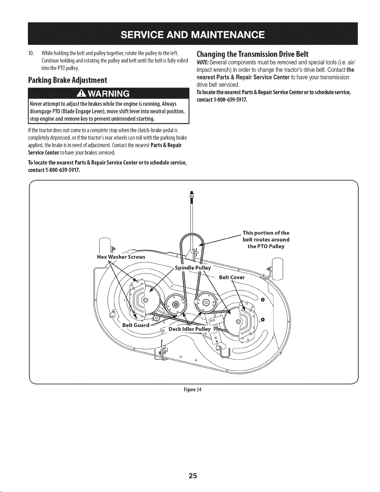
10. Whileholdingthe belt andpulleytogether,rotatethe pulleyto the left.
Continueholdingandrotatingthepulleyandbelt untilthebelt isfully rolled
into thePTOpulley.
ParkingBrakeAdjustment
Neverattempt to adjustthe brakeswhile theengineisrunning. Always
disengagePTO(BladeEngageLever),moveshift [everinto neutralposition,
stopengine andremovekeyto preventunintendedstarting.
Changing the TransmissionDrive ieit
NOTE:Several components must be removed and special tools (i.e. air/
impact wrench) in order to change the tractor's drive belt. Contact the
nearest Parts & Repair Service Center to have your transmission
drive belt serviced.
Tolocatethe nearestParts& RepairServiceCenteror to scheduleservice,
contact1-800-659-5917.
If thetractordoesnotcometoa completestopwhentheclutch-brakepedalis
completelydepressed,or if thetractor'srearwheelscanrollwith theparkingbrake
applied,thebrakeis inneedof adjustment.Contactthe nearestParts & Repair
ServiceCenterto haveyourbrakesserviced.
Tolocate the nearestParts& RepairServiceCenter or to scheduleservice,
contact1-800-659-5917.
f
Figure 24
J
25
Neverstore lawn tractor with fuel in tankindoorsor inpoorlyventilated
areaswhere fuel fumes may reachanopen flame, spark,or pilot light ason
a furnace,water heater, clothesdryer,or gasappliance.
PreparingTheEngine
IM PORTANT: Fuelleft inthefueltank duringwarmweatherdeterioratesand
will causeseriousstartingproblems.
Topreventgumdepositsfromforminginsidetheengine'scarburetorandcausing
possiblemalfunctionoftheengine,thefuel systemmustbeeithercompletely
emptied,or thegasolinemustbetreatedwith astabilizerto preventdeterioration.
I. Ifusingafuelstabilizer:
a. Readthe productmanufacturer'sinstructionsandrecommendations.
b. Addto clean,freshgasolinethecorrectamountof stabilizerfor the
capacityofthe fuel system.
c. Fillthefueltankwith treatedfuel andrunthe enginefor2-3minutesto
getstabilizedfuel intothecarburetor.
2. Ifemptyingthefuelsystem:
a. Donot drainfuel whenthe engineishot.Allowtheengineadequate
timeto cool.Drainfuel into anapprovedcontaineroutdoors,awayfrom
openflame.
b. Drainanylargevolumeof fuelfrom thetank bydisconnectingthe
fuel linefromthe in-linefuelfilter nearthe engine.Seethecomplete
instructionsforDrainingTheFuellaterin thissection.
Gasolineisextremely flammable and canbe explosiveundercertain
conditions. Draingasolinebeforestoring theequipment for extended
periods.Drainfuel only into anapprovedcontaineroutdoors,awayfrom
an open flame. Allow engine to cool.Extinguishcigarettes, cigars,pipes,
and othersourcesof ignition prior to draining fuel. Storegasolineinan
approvedcontainer in safelocation.
c. Reconnectthefuel lineandruntheengineuntil it startsto falter,then
usethechoketo keeptheenginerunninguntilall fuelinthecarburetor
hasbeenexhausted.
d. Disconnectthe fuellineanddrainanyremaininggasolinefromthe
system.
DrainingThe Fuel
1. Locatethefuel filter,whichis locatedon the left sideoftheengine,andmay
beattachedto theenginewith a tiestrap.
2. Cutthe tie strap,if present,thenpinchthe in-lineclamponthe fuel filter
with a pairof pliers,slidethe clampupthefuel line.
3. Pullthefuel linefreefrom the filterandplacetheopenendof thelineinto
an approvedcontainerto drainthe fuel.
PreparingThelawn tractor
Cleanandlubricatetractorthoroughlyasdescribedinthelubrication
instructions.
2. Donotusea pressurewasherorgardenhoseto cleanyourunit.
3. Storemowerinadry,cleanarea.Donotstorenextto corrosivematerials,
suchasfertilizer.
Gasolineisa toxic substance.Disposeof gasolineproperly.Contactyour
localauthorities for approveddisposalmethods.
3. Removethesparkplugandpourone(1)ounceofengineoil throughthespark
plugholeinto the cylinder.Crankthe engineseveraltimesto distributethe
oil. Replacethesparkplug.
26

Enginefailsto start
Enginerunserratically
1. PTO/BladeEngageleverengaged.
2. Parkingbrakenotengaged.
3. Sparkplugwire(s) disconnected.
4. Throttle/Chokecontrollevernot in correct
startingposition.
5. Chokenotactivated
6. Fueltank empty,or stale fuel.
7. Blockedfuel line.
8. Faultysparkplug(s).
9. Engineflooded.
10. BlownFuse(s)
1. UnitrunningwithCHOKEactivated.
2. Sparkplugwire(s) loose.
3. Blockedfuel lineor stalefuel.
4. Ventingas cap plugged.
5. Wateror dirt in fuel system.
6. Dirtyair cleaner.
Engineoverheats 1. Engineoil levellow. 1.
2. Air flowrestricted. 2.
Enginehesitatesat high RPM 1. Sparkpluggaptoo close. 1.
Engineidles rough 1. Sparkplugfouled,faultyor gap too wide. 1.
2. Dirtyair cleaner. 2.
Excessivevibration
Mowerwill not mulchgrass
Unevencut
1. Cuttingbladelooseor unbalanced.
2. Damagedorbent cuttingblade.
1. Enginespeedtoo low.
2. Wetgrass.
3. Excessivelyhighgrass.
4. Dullblade.
1. Decknot leveledproperly.
2. Dullblade.
3. Uneventire pressure.
1. Placeleverindisengaged(OFF) position.
2. Engageparkingbrake.
3. Connectwire(s)to sparkplug(s).
4. PlaceThrottle/Chokeleverintothe FASTposition.
5. MovetheThrottle/Chokeleverintothe Choke
position.
6. Filltank with clean,fresh (less than 30days old) gas.
7. Replacethe fuel lineand replacefuel filter.
8. Clean,adjustgapor replaceplug(s).
9. Crankenginewiththrottlein FASTposition.
10. ReplaceFuse(s)See"Fuse"in Serviceand
Maintenancesection.
1. Deactivatethe CHOKE.
2. Connectsparkplugwire(s).
3. Replacethe fuel line;fill tankwith clean,fresh
gasolineandreplacefuel filter.
4. Clearventor replacecap if damaged.
5. Drainfuel tank. Refillwithclean,freshgasoline.
6. Replaceair cleanerpaper elementor cleanfoam
pre-cleaner,if equipped.
Fillcrankcasewithproperamountandweightof oil.
Cleangrassclippingsanddebrisfrom aroundthe
engine'scoolingfins and housing.
Removesparkplugandresetthe gap.
Replacesparkplug.Set pluggap.
Replaceair cleanerelementand/orcleanpre-
cleaner.
1. Tightenbladeand spindle.
2. Replaceblade.
1. Placethrottlein FAST(rabbit)position.
2. Do notmulchwhen grassis wet.
3. Mowonceat a highcuttingheight,then mowagain
at desiredheightor makea narrowercuttingswath.
4. Sharpenor replaceblade.
1. Performside-to-sidedeck adjustment.
2. Sharpenor replaceblade.
3. Checktire pressurein all four tires.
NEED MORE HELP?
Find this and a[[ your other product manuals online.
Get answers from our team of home experts.
Get a personalized maintenance ptan for your home.
Find information and tools to help with home projects.
27
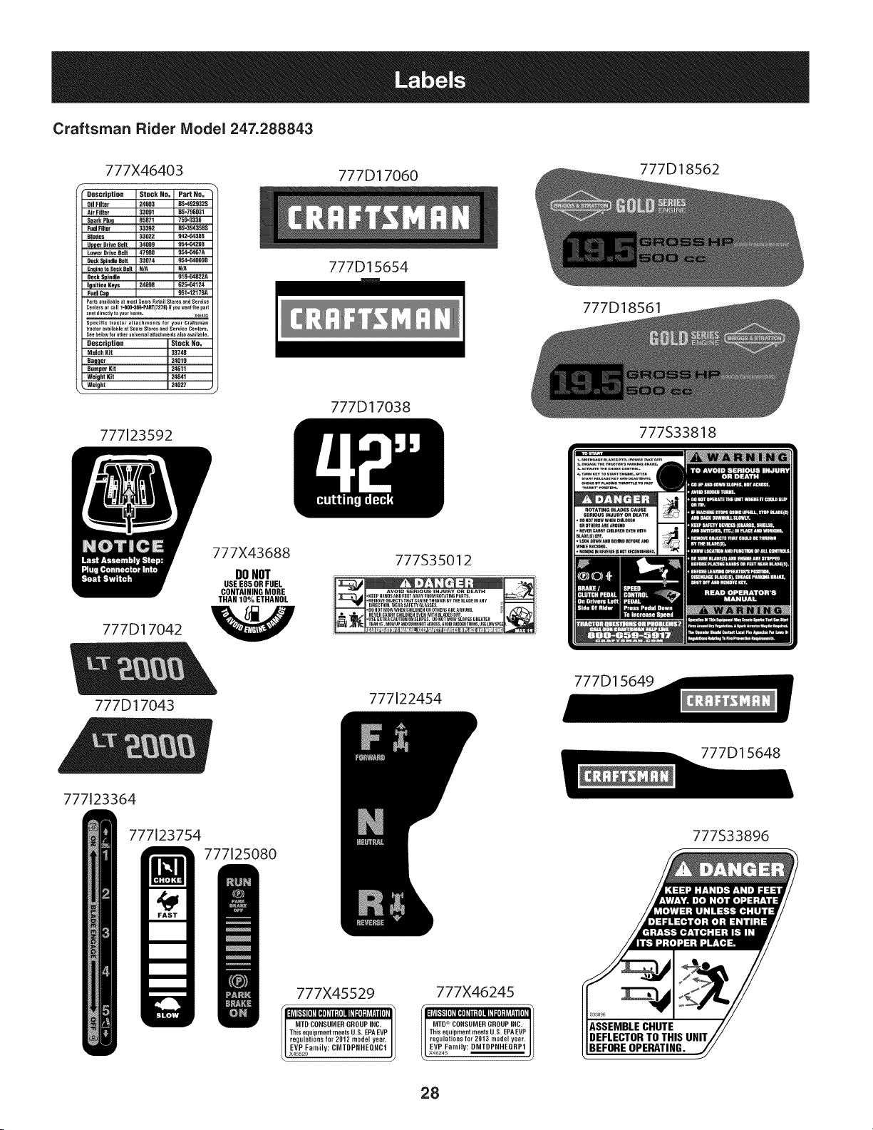
Craftsman Rider Model 247.288843
777X46403 777D17060 777D18562
• Description Stock NO. Part No.
Oil Filter 24683 D3-492932S
Air Filter 33991 D3-796931
Spark PJuq 89371 759"3336
Fuel Filter 33392 D3-3983983
DJades 33022 942"04308
_er Drive Belt 34909 954_68208
Lower Drive Bait 47900 95_08878
Deck S_ndle Belt 33074 954=OdD60D
Enq81eto Deck DOlt H/A N]A
Deck Spindle 918-048228
Igeltten Keys 24698 625-94124
Fuel Cap 951-121798
Pa+tsavmilahleat mosl Sears RetailSt+resamdSe+vi+e
Ce_+e_or_.II I-SOO._+-PART(7_TS)ifW" wan+thepart
sent_irectlvto yo_Phome. ×+_o3
Spec_f+c tractor attachments for yo,r Craftsman
tm_tor_va+lableat Se_rs St_es an_ Se_v_e Centers.
See _elo_formhe_un+vers_lanac_mentsalso avml_le.
Dascriptialm Stock Ha=
M.lch Kit 33788
Ba91]er 24019
Bumper Klt _611
WeiuhtKit 34641
_, Weight
J
777123592
777D15654
777D17038
777D18561
777D17042
777D17043
777X43688
DONOT
USE E85 OR FUEL
CONTAINING MORE
THAN 10% ETHANOL
777S35012
• REMOVEOBJECTSTHATCANBETHROWNBYTHEeLADEINABY
DIRECTION.W_ARSAFETYGLASSES.
• DOHOTMOWWHEHCHILDHEHOROTHERSAREAROUHD.
[ HEVERCARRYCHILDREHEVEHWITHBLADESOFF.
• USEEXTRACAUTIONONSLOPE&O0HOTmOWSLOPESGREATER
777122454
777S33818
777D15649
777123364
777123754
777125080
777X45529
[ MTD CONSUMER GROUPINC,
This equipnlent meets U.S. EPA EVP
regulations for 2012 model year.
EVP Family: CMTDPRHEQRC1
L x45529
777X46245
EVP family: DMTDPNHEURP1
MTD CONSUMER GROUPINC,
This equipment meets U.S. EPAEVP
regulations for 2013 model year.
I* X46245
BEFOREOPERATING.
777D15648
777S33896
28

This page intentionally left blank. Use this page to make any notes regarding your tractor.
29
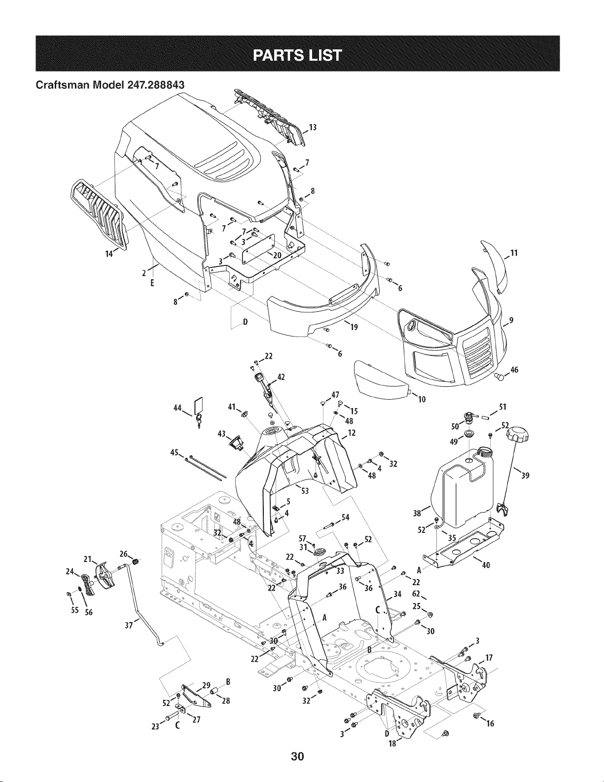
Craftsman IViodel 247.288843
14" 11
42
/ 5
4
\\\
22
lo
51
50/_ 52
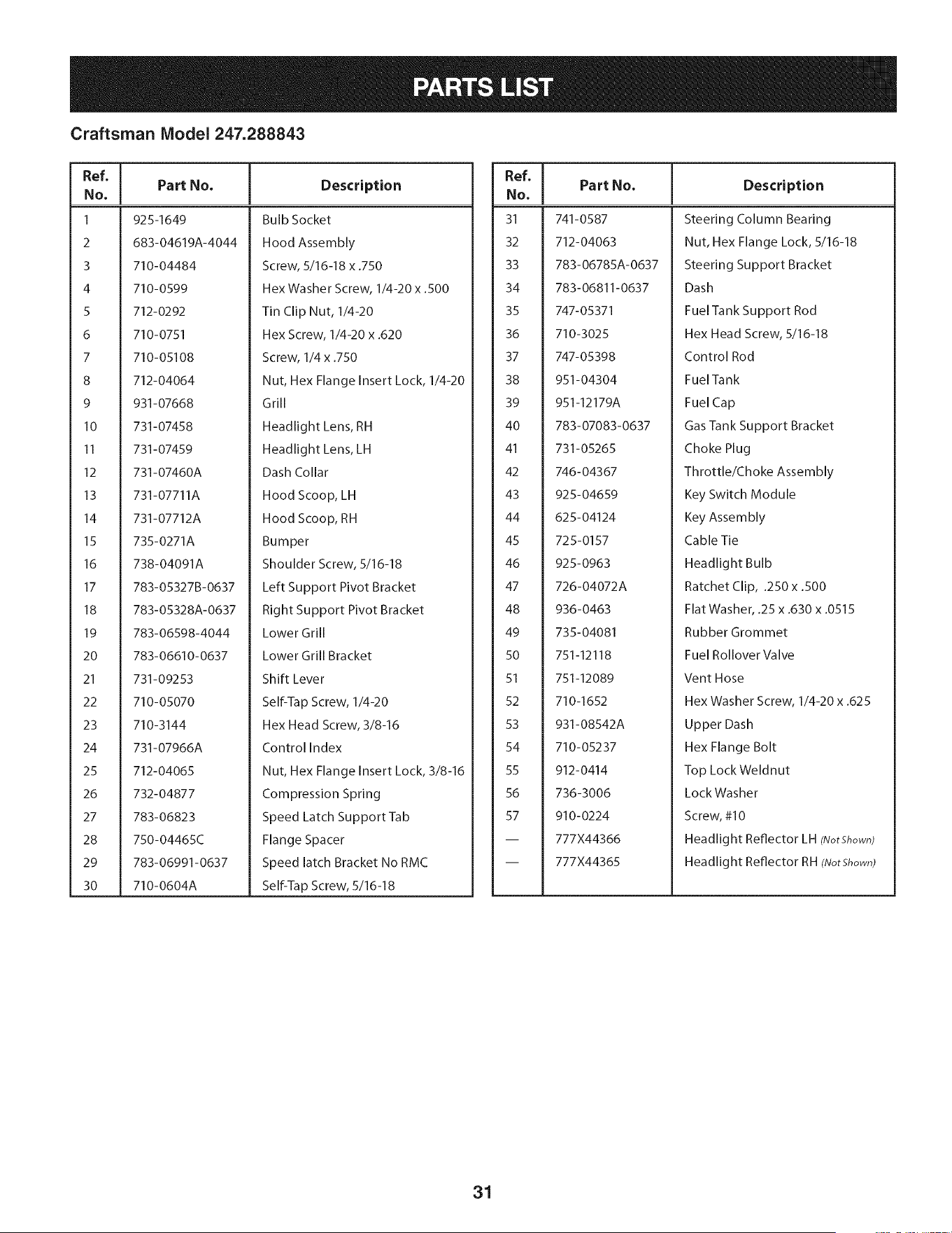
Craftsman Model 247.288843
Ref, [
No.
1 925-I 649
2 683-04619A-4044
3 710-04484
4 710-0599
S 712-0292
6 710-0751
7 710-05108
8 712-04064
9 931-07668
lO 731-07458
II 731-07459
12 731-07460A
13 731-07711A
14 731-07712A
15 735-0271A
16 738-04091A
17 783-05327B-0637
18 783-05328A-0637
19 783-06598-4044
20 783-06610-0637
21 731-09253
22 710-05070
23 710-3144
24 731-07966A
25 712-04065
26 732-04877
27 783-06823
28 750-04465C
29 783-06991-0637
30 710-0604A
Part No. Description
Bulb Socket
Hood Assembly
Screw, 5/16-18 x .750
Hex Washer Screw, 1/4-20 x .500
Tin Clip Nut, 1/4-20
Hex Screw, 1/4-20 x .620
Screw, 1/4 x .750
Nut, Hex Flange Insert Lock, 1/4-20
Grill
Headlight Lens, RH
Headlight Lens, LH
Dash Collar
Hood Scoop, LH
Hood Scoop, RH
Bumper
Shoulder Screw, 5/16-18
Left Support Pivot Bracket
Right Support Pivot Bracket
Lower Grill
Lower Grill Bracket
Shift Lever
Self-Tap Screw, 1/4-20
Hex Head Screw, 3/8-16
Control Index
Nut, Hex Flange Insert Lock, 3/8-16
Compression Spring
Speed Latch Support Tab
Flange Spacer
Speed latch Bracket No RMC
Self-Tap Screw, 5/16-18
Ref, I
No,
31 741-0587
32 712-04063
33 783-06785A-0637
34 783-06811-0637
35 747-05371
36 710-3025
37 747-05398
38 951-04304
39 951-12179A
40 783-07083-0637
41 731-05265
42 746-04367
43 925-04659
44 625-04124
45 725-0157
46 925-0963
47 726-04072A
48 936-0463
49 735-04081
50 751-12118
51 751-12089
52 710-1652
53 931-08542A
54 710-05237
55 912-0414
56 736-3006
57 910-0224
-- 777X44366
-- 777X44365
Part No, Description
Steering Column Bearing
Nut, Hex Flange Lock, 5/16-18
Steering Support Bracket
Dash
Fuel Tank Support Rod
Hex Head Screw, 5/16-18
Control Rod
FuelTank
Fuel Cap
Gas Tank Support Bracket
Choke Plug
Throttle/Choke Assembly
Key Switch Module
Key Assembly
Cable Tie
Headlight Bulb
Ratchet Clip, .250 x .500
Flat Washer, .25 x .630 x .0515
Rubber Grommet
Fuel Rollover Va Ive
Vent Hose
Hex Washer Screw, 1/4-20 x .625
Upper Dash
Hex Flange Bolt
Top Lock Weldnut
LockWasher
Screw, #10
Headlight Reflector LH (NotShown)
Headlight Reflector RH (NotShown)
31
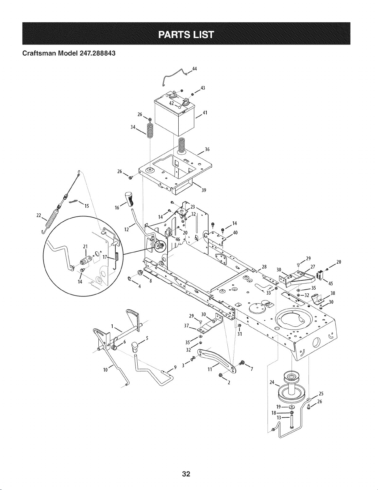
Craftsman IViodel 247.288843
22
14
21
12
39
3O
45
38
11
%
2
32
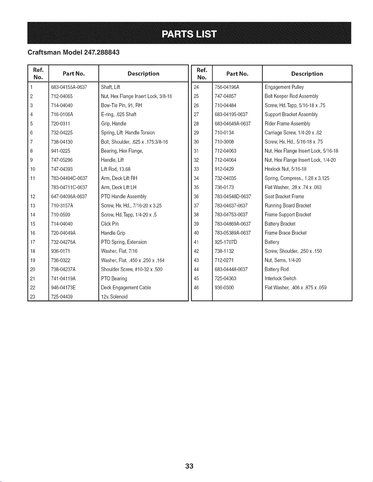
Craftsman IViodel 247.288843
I
Ref.
I Part No.
No,
I
1 683-04155A-0637
2 712-04065
3 714-04040
4 716-0106A
5 720-0311
6 732-04225
7 738-04130
8 941-0225
9 747-05296
10 747-04393
11 783-04494C-0637
783-04711C-0637
12 647-04096A-0637
13
14
15
16
17
18
19
2O
21
22
23
Description
710-3157A
710-0599
714-04040
720-04049A
732-04276A
936-0171
736-0322
738-04237A
741-04119A
946-04173E
725-04439
Shaft,Lift
Nut,Hex FlangeInsert Lock,3/8-16
Bow-TiePin, 91,RH
E-ring,.625Shaft
Grip,Handle
Spring,Lift HandleTorsion
Bolt,Shoulder,.625x .175:3/8-16
Bearing,HexFlange,
Handle,Lift
Lift Rod, 13.68
Arm, DeckLift RH
Arm, DeckLiftLH
PTOHandleAssembly
Screw,Hx.Hd., 7/16-20x 3.25
Ref,
Part No,
No,
24 756-04196A
25 747-04857
26 710-04484
27 683-04195-0637
28 683-04649A-0637
29 710-0134
30 710-3008
31 712-04063
32 712-04064
33 912-0429
34 732-04035
35 736-0173
36 783-04548D-0637
37 783-04637-0637
Description
EngagementPulley
Belt KeeperRodAssembly
Screw,Hd.Tapp,5/16-18x .75
SupportBracketAssembly
RiderFrameAssembly
CarriageScrew,1/4-20x .62
Screw,Hx. Hd.,5/16-18x .75
Nut, HexFlangeInsertLock,5/16-18
Nut, HexFlangeInsertLock,1/4-20
HexlockNut, 5/16-18
Spring,Compress.,1.28x 3.125
FlatWasher,.28x .74x .063
Seat BracketFrame
RunningBoardBracket
Screw,Hd.Tapp,1/4-20x .5
ClickPin
HandleGrip
PTOSpring,Extension
Washer,Flat,7/16
38 783-04753-0637
39 783-04869A-0637
40 783-05389A-0637
41 925-1707D
42 738-1132
FrameSupport Bracket
BatteryBracket
FrameBrace Bracket
Battery
Screw,Shoulder,.250x .150
Washer,Fiat,.450x .250x .164
ShoulderScrew,#10-32x .500
PTOBearing
DeckEngagementCable
12v.Solenoid
43 712-0271
44 683-04448-0637
45 725-04363
46 936-0300
Nut, Sems,1/4-20
BatteryRod
InterlockSwitch
FlatWasher,.406x .875 x .059
33
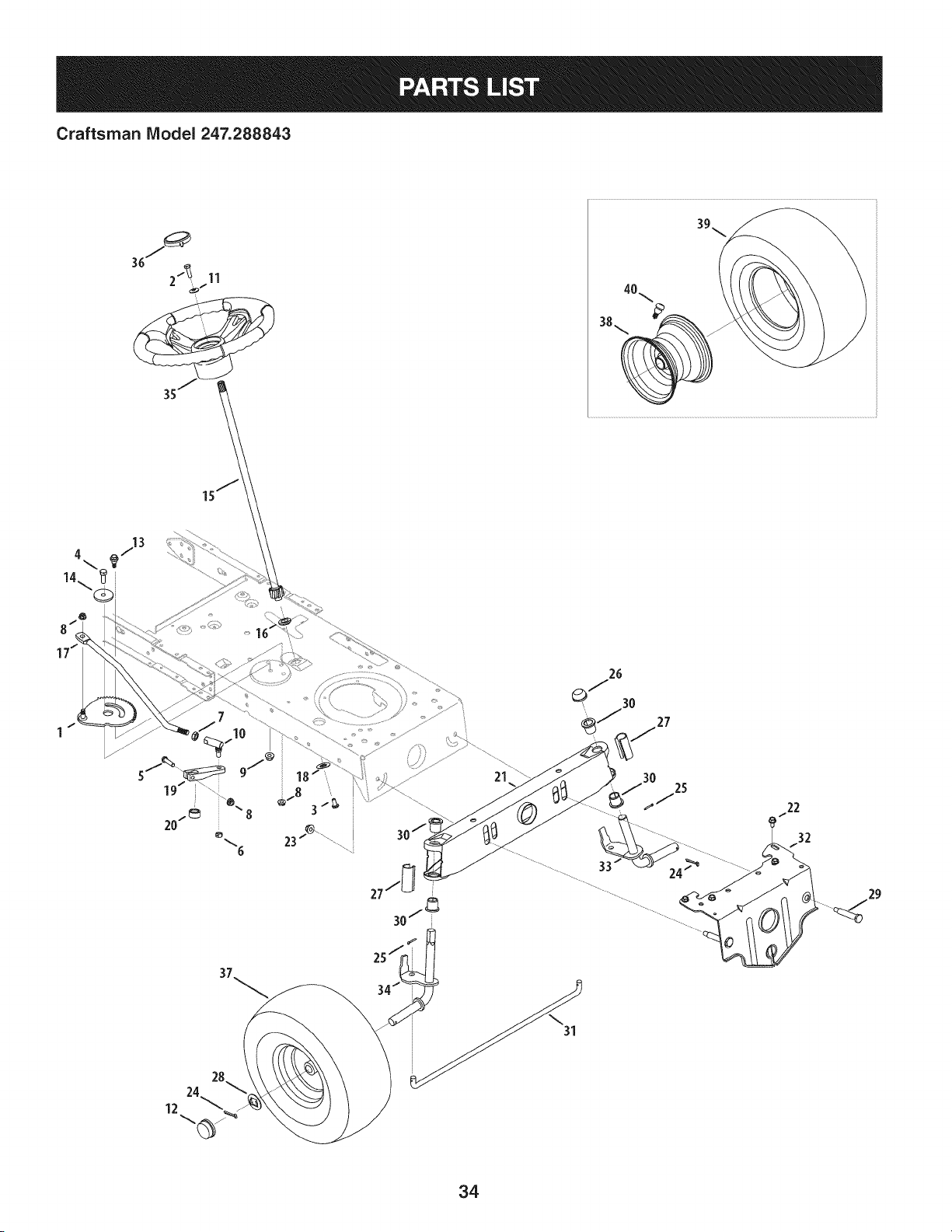
Craftsman IViodel 247.288843
39
38._ _ z
4 713
21
30
25
24 _ ............
22
32
/
34
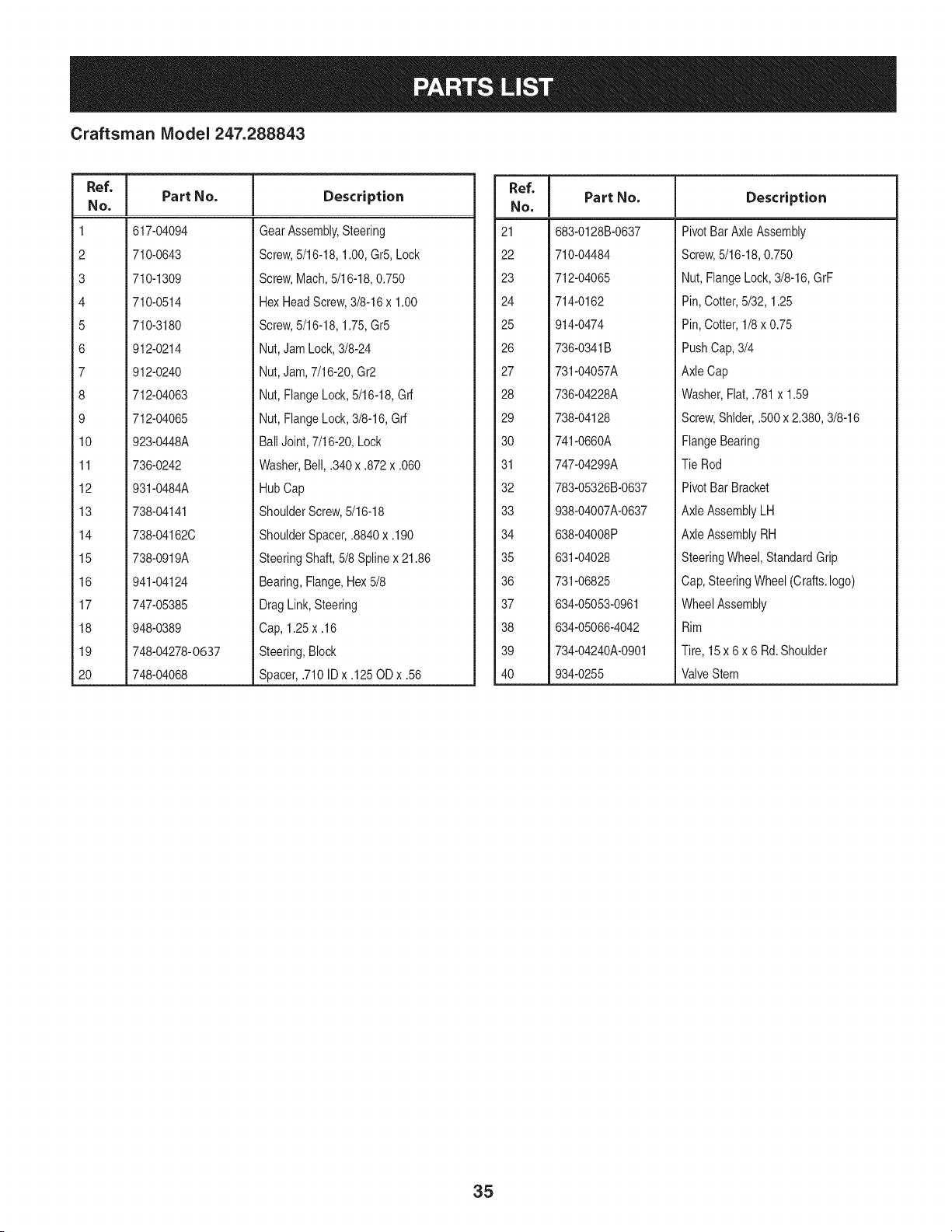
Craftsman IViodel 247.288843
Ref, I
No.
1 617-04094
2 710-0643
3 710-1309
4 710-0514
5 710-3180
6 912-0214
7 912-0240
8 712-04063
9 712-04065
10 923-0448A
11 736-0242
12 931-0484A
13 738-04141
14 738-04162C
15 738-0919A
16 941-04124
17 747-05385
18 948-0389
19 748-04278-0637
20 748-04068
Part No. Description
GearAssembly,Steering
Screw,5/16-18,1.00,Gr5,Lock
Screw,Mach,5/16-18,0.750
HexHeadScrew,3/8-16x 1.00
Screw,5/16-18,1.75,Gr5
Nut,JamLock,3/8-24
Nut,Jam,7/16-20,Gr2
Nut,FlangeLock,5/16-18,Grf
Nut,FlangeLock,3/8-16,Grf
BallJoint, 7/16-20,Lock
Washer,Bell, .340x .872x .060
HubCap
ShoulderScrew,5/16-18
ShoulderSpacer,.8840x .190
SteeringShaft,5/8 Splinex 21.86
Bearing,Flange,Hex5/8
DragLink,Steering
Cap, 1.25x .16
Steering,Block
Spacer,.710ID x .125OD x .56
Ref. I
No.
21 683-0128B-0637
22 710-04484
23 712-04065
24 714-0162
25 914-0474
26 736-0341B
27 731-04057A
28 736-04228A
29 738-04128
30 741-0660A
31 747-04299A
32 783-05326B-0637
33 938-04007A-0637
34 638-04008P
35 631-04028
36 731-06825
37 634-05053-0961
38 634-05066-4042
39 734-04240A-0901
40 934-0255
Part No, Description
PivotBar AxleAssembly
Screw,5/16-18,0.750
Nut, FlangeLock,3/8-16,GrF
Pin, Cotter,5/32, 1.25
Pin, Cotter,1/8 x 0.75
PushCap,3/4
AxleCap
Washer,Flat,.781x 1.59
Screw,Shlder,.500x 2.380,3/8-16
FlangeBearing
TieRod
PivotBar Bracket
AxleAssemblyLH
AxleAssemblyRH
SteeringWheel,StandardGrip
Cap,SteeringWheel(Crafts.logo)
WheelAssembly
Rim
Tire, 15 x 6 x 6 Rd.Shoulder
ValveStem
35

Craftsman Model 247.288843
13
11
\
36
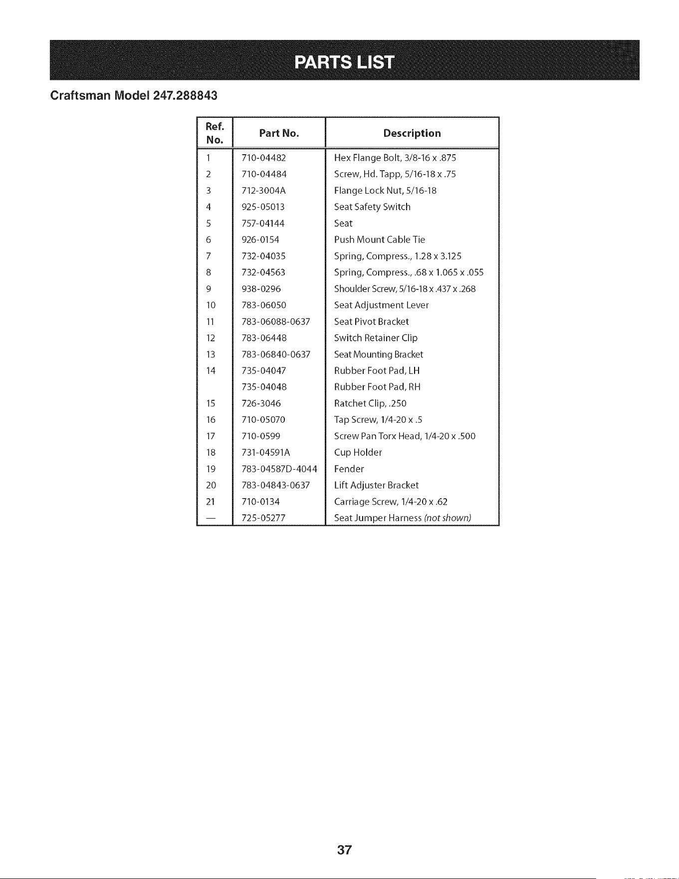
Craftsman Model 247.288843
Ref, [
No,
I 710-04482
2 710-04484
3 712-3004A
4 925-05013
5 757-04144
6 926-0154
7 732-04035
8 732-04563
9 938-0296
10 783-06050
11 783-06088-0637
12 783-06448
13 783-06840-0637
14 735-04047
735-04048
15 726-3046
16 710-05070
17 710-0599
18 731-04591A
19 783-04587D-4044
20 783-04843-0637
21 710-0134
-- 725-05277
Part No. Description
Hex Flange Bolt, 3/8-16 x .875
Screw, Hd.-lapp, 5/16-18 x .75
Flange Lock Nut, 5/16-18
Seat Safety Switch
Seat
Push Mount Cable Tie
Spring, Compress., 1.28 x 3.125
Spring, Compress., .68 x 1.065 x .055
Shoulder Screw, 5/16-18 x .437 x .268
Seat Adjustment Lever
Seat Pivot Bracket
Switch Retainer Clip
Seat Mounting Bracket
Rubber Foot Pad, LH
Rubber Foot Pad, RH
Ratchet Clip, .250
Tap Screw, 1/4-20 x .5
Screw Pan Torx Head, 1/4-20 x .500
Cup Holder
Fender
Lift Adjuster Bracket
Carriage Screw, 1/4-20 x .62
Seat Ju m per Ha mess (not shown)
37
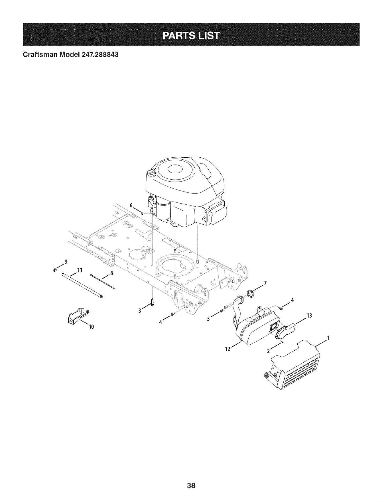
Craftsman IViodel 247.288843
13
38
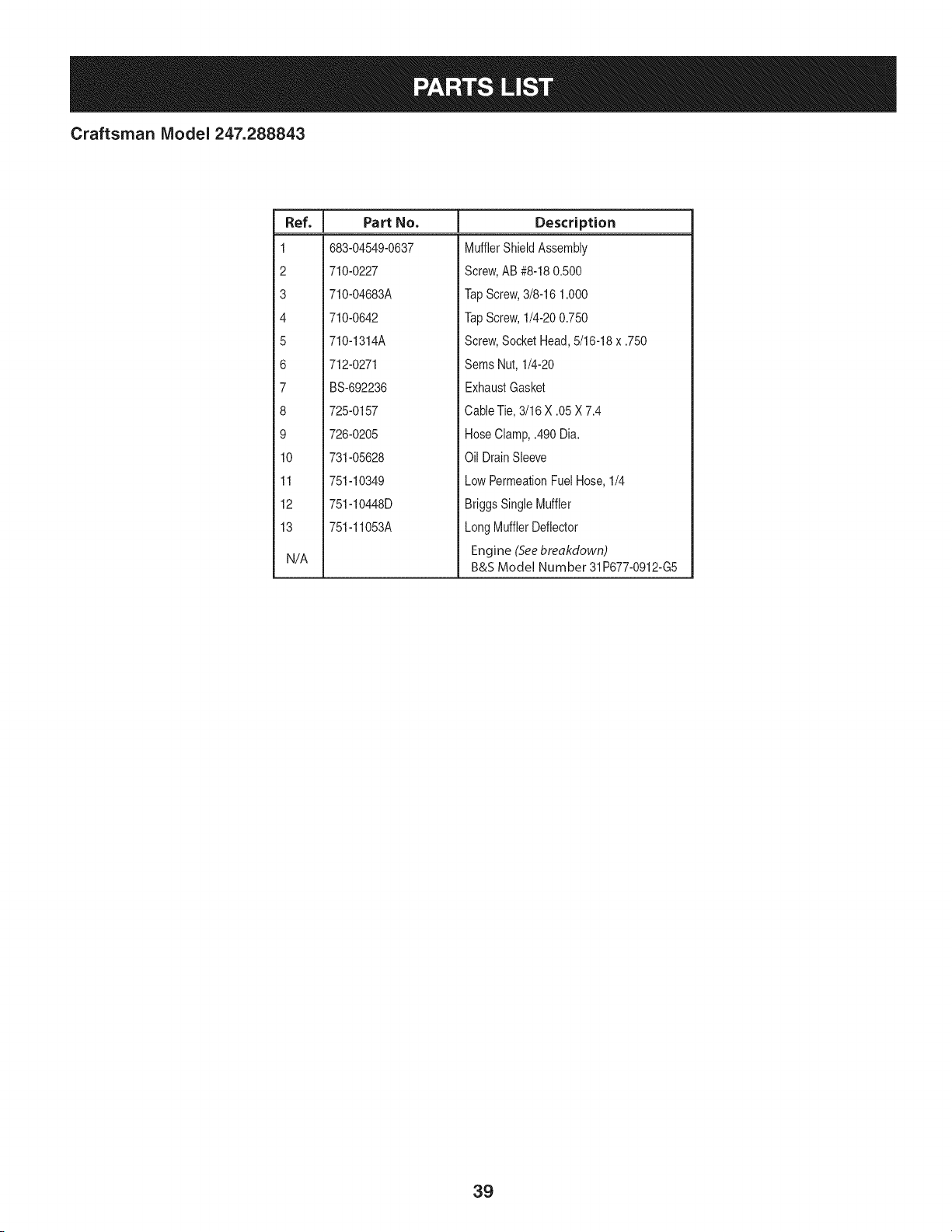
Craftsman IViodel 247.288843
I
Ref.
I Part No.
1 683-04549-0637
2 710-0227
3 710-04683A
4 710-0642
5 710-1314A
6 712-0271
7 BS-692236
8 725-0157
9 726-0205
10 731-05628
11 751-10349
12 751-10448D
13 751-11053A
N/A
Description
MufflerShieldAssembly
Screw,AB #8-180.500
TapScrew,3/8-16 1.000
TapScrew,1/4-200.750
Screw,SocketHead,5/16-18x .750
Sems Nut, 1/4-20
ExhaustGasket
CableTie,3/16 X .05 X 7.4
HoseClamp,.490 Dia.
Oil DrainSleeve
LowPermeationFuelHose,1/4
BriggsSingleMuffler
LongMufflerDeflector
Engine (Seebreakdown)
B&S Model Number 31P677-0912-G5
39
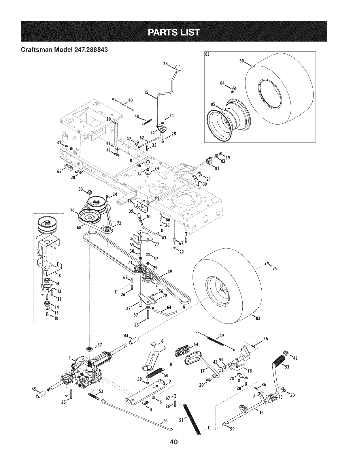
Craftsman Model 247.288843
31
4O
83
19
72
69
B
2
201
4O
18
36
/
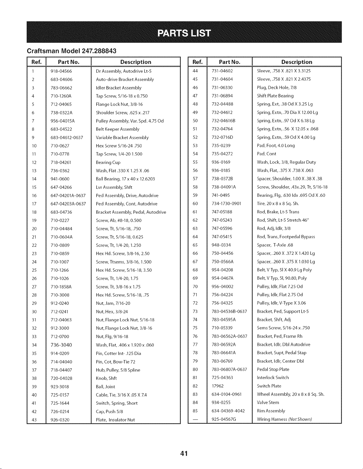
Craftsman Model 247.288843
I
Ref, I Part No.
1 918-04566
2 683-04606
3 783-06662
4 710-1260A
5 712-04065
6 738-0322A
7 956-04015A
8 683-04522
9 683-04612-0637
10 710-0627
11 710-0778
12 718-04261
13 736-0362
14 941-0600
15 647-04266
16 647-04201A-0637
17 647-04203A-0637
18 683-04736
19 710-0227
20 710-04484
21 710-0604A
22 710-0809
23 710-0859
24 710-1007
25 710-1266
26 710-1026
27 710-1858A
28 710-3008
29 912-0240
30 712-0241
31 712-04063
32 912-3000
33 712-0700
34 736-3040
35 914-0209
36 714-04040
37 718-04407
38 720-04028
39 923-3018
40 725-0157
41 725-1644
42 726-0214
43 926-0320
Description
Dr Assembly, Autodrive Lt-5
Auto-drive Bracket Assembly
Idler Bracket Assembly
Tap Screw, 5/16-18 x 0.750
Flange Lock Nut, 3/8-16
Shoulder Screw, .625 x .217
Pulley Assembly, Var. Spd. 4.75 Od
Belt Keeper Assembly
Variable Bracket Assembly
Hex Screw 5/16-24.750
Tap Screw, 1/4-20 1.500
Bearing Cup
Wash, Flat .330 X 1.25 X .06
Ball Bearing, 17 x 40 x 12.6203
Lvr Assembly, Shft
Ped Assembly, Drive, Autodrive
Ped Assembly, Cont, Autodrive
Bracket Assembly, Pedal, Autodrive
Screw, Ab, #8-18, 0.500
Screw, Tt, 5/16-18, .750
Screw, Tt, 5/16-18, 0.625
Screw, Tt, 1/4-20, 1.250
Hex Hd. Screw, 3/8-16, 2.50
Screw, Ttsems, 3/8-16, 1.500
Hex Hd. Screw, 5/16-18, 3.50
Screw, Tt, 1/4-20, 1.75
Screw, Tt, 3/8-16 x 1.75
Hex Hd. Screw, 5/16-18, .75
Nut, Jam, 7/16-20
Nut, Hex, 3/8-24
Nut, Flange Lock Nut, 5/16-18
Nut, Flange Lock Nut, 3/8-16
Nut, Fig, 9/16-18
Wash, Flat, .406 x 1.920 x .060
Pin, Cotter Int- .125 Dia
Pin, Cot, Bow-Tie 72
Hub, Pulley, 5/8 Spline
Knob, Shft
Ball, Joint
Cable, Tie, 3/16 X .05 X 7.4
Switch, Spring, Short
Cap, Push 5/8
Plate, Insulator Nut
|
Ref, I Part No.
44 731-04602
45 731-04604
46 731-06330
47 731-06894
48 732-04488
49 732-04612
50 732-04616B
51 732-04764
52 732-0716D
53 735-0239
54 735-04272
55 936-0169
56 936-0185
57 738-0372B
58 738-04091A
59 741-0495
60 734-1730-0901
61 747-05188
62 747-05243
63 747-05596
64 747-05415
65 948-0334
66 750-04456
67 750-0566A
68 954-04208
69 954-0467A
70 956-04002
71 756-04224
72 756-04325
73 783-04536B-0637
74 783-04595A
75 710-05339
76 783-06562A-0637
77 783-06592A
78 783-06641A
79 783-06769
80 783-06807A-0637
81 725-04363
82 17962
83 634-0104-0961
84 934-0255
85 634-04369-4042
-- 925-04567G
Description
Sleeve, .758 X .821 X 3.3125
Sleeve, .758 X .821 X 2.4375
Plug, Deck Hole, 7/8
Shift Plate Bearing
Spring, Ext, .38 Od X 3.25 Lg
Spring, Extn, .70 Dia X 12.00 Lg
Spring, Extn, .97 Od X 6.18 Lg
Spring, Extn, .56 X 12.05 x .068
Spring, Extn, .59 Od X 4.00 Lg
Pad, Foot, 4.0 Long
Pad, Cont
Wash, Lock, 3/8, Regular Duty
Wash, Flat, .375 X .738 X .063
Spacer, Shoulder, 1.00 X .38 X .38
Screw, Shoulder, A3x.29, Tt, 5/16-18
Bearing, Fig, .630 Idx .695 Od X .60
Tire, 20 x 8 x 8 Sq. Sh.
Rod, Brake, Lt-5 Trans
Rod, Shift, Lt-5 Stretch 46"
Rod, Adj, Idlr, 3/8
Rod, Trans, Footpedal Bypass
Spacer, T-Axle .68
Spacer, .260 X .372 X 1.420 Lg
Spacer, .260 X .375 X 1.030 Lg
Belt, V Typ, 51 X 40.9 Lg Poly
Belt, V Typ, 51, 90.80, Poly
Pulley, Idlr, Flat 7.25 Od
Pulley, Idlr, Flat 2.75 Od
Pulley, Idlr, V-Type X 3.06
Bracket, Ped, Support Lt-5
Bracket, Shft, Adj
Sems Screw, 5/16-24 x .750
Bracket, Ped, Frame Rh
Bracket, Idlr, Dbl Autodrive
Bracket, Supt, Pedal Stap
Bracket, Idlr, Center Dbl
Pedal Stop Plate
Interlock Switch
Switch Plate
Wheel Assembly, 20 x 8 x 8 Sq. Sh.
Valve Stem
Rim Assembly
Wiring Harness (NotShown)
41
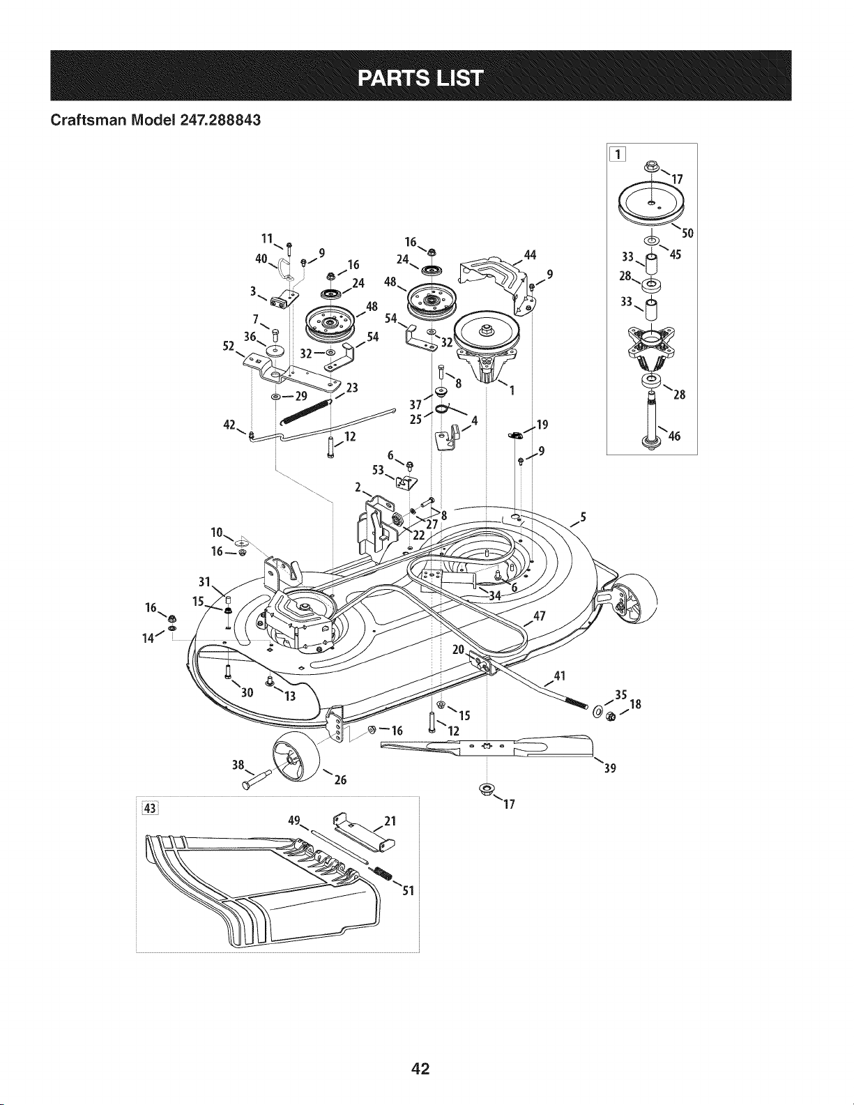
Craftsman IViodel 247.288843
44
I
[]
"50
33 ._ "45
28._
33. t
G
10..
38
25
41
J
35
/ 18
39
42

Craftsman Model 247.288843
I
Ref. I Part Number
1. 918-04822A
2. 683-0254B-0637
3. 983-04511
4. 983-04525
5. 983-04572A-0637
6. 710-04484
Z 710-3005
8. 710-0528
9. 710-0599
10. 936-3039
11. 710-0642
12. 710-3144
13. 710-3178
14. 712-0229
15. 712-04063
16. 712-04065
17. 712-0417A
18. 712-04243
19. 783-06464
20. 714-04043
21. 783-06074A
22. 917-04074
23. 932-0384
24. 783-07236
25. 732-04840
26. 734-04155
27. 936-0119
Description
Spindle Ass'y, Pulley, 6.3 Dia
Bracket Ass'y, Deck, Hanger LH
Brake Ass'y, Deck, 42/46
Brake Ass'y, Deck, 46"
Deck Ass'y, Offset, 42"
Screw, Self-tapping, 5/16-18, .750
Hex Screw, 3/8-16, 1.25, Gr5, Std
Hex Screw, 5/16-18, 1.25, Gr5, Std
Screw, Self-tapping, 1/4-20, 0.500
Flat Washer, .406 x 1.500 x .105
Screw, Self-tapping, 1/4-20, .750
Hex Screw, 3/8-16, 2.00, Gr5, Std
Bolt, Carriage, 3/8-16, 0.75, Grl
Nut, Push, 3/8
Nut, Flange Lock, 5/16-18, Grf
Nut, Flange Lock, 3/8-16, Grf
Nut, Flange, 5/8-18
Nut, Lock, 1/2-13
Deck Wash Plug
Bow-Tie Cotter Pin
Chute Bracket
Gear, Deck, Adjustment
Spring, Extension, .62 Dia x 6.12
Pulley Cap
Spring, Torsion, .992 ID X 1.17 OD
Wheel, Deck, 5.0 Dia Ball
Washer, Lock, 5/16, Regular Duty
I
Ref. I Part Number
28. 941-0919A
29. 936-0344
30. 710-0376
31. 720-05010
32. 736-0262
33. 750-04936
34. 783-06643
35. 748-04069
36. 738-04162C
3Z 748-04272
38. 938-3056
39. 942-04308
40. 747-05323
41. 747-05141A
42. 747-05105B
43. 631-04288
44. 783-06424A
45. 936-0351
46. 738-1186A
47. 954-04060B
48. 756-04129B
49. 711-04847B
50. 956-1227
51. 732-04372
52. 783-05946
53. 783-06243
54. 783-06368A
Description
Bearing, Ball, .787id x 1.85 Odx.551
Washer, Flat, .385 X 1.0 X .030
Hex Cap Screw, 5/16-18 x 1.00
Cap, .290 x .500
Washer, Flat, .385 x .870 x .092
Spacer, .792 x 1.060 x 1.860
Bracket, Support, Stationary Idler
Deck Lift Pivot Cup
Spacer, Shoulder, .8840 x .190
Shoulder Spacer
Bolt, Shoulder, .496 x 2.50, 3/8-16
Blade, Cut, 21.23" 2-1n-1, Econ
Rod, Keepr, Belt 42 Idler
Rod, Lift, Deck, Frt, 12.7
Rod, Control, Brake 42"
Chut Assembly, 42" Deck
Deck Belt Cover, 42
Washer, Flat, .760 Idxl.50 OD
Shift, Spindle, 6.11.
Belt, V Type, A Sec X 96.5
Pulley, Idler, 4.25"Dia
Pin, Hinge, Dia .3125 x 7.96
Pulley, Deck, 6.3 Dia
Spring, Torsion, .44 I.D. X 2.0
Pivot idler Bracket, 46
Bracket, Cable, Deck Engage
Bracket, Guard, Belt, 4.25 Pulley
43
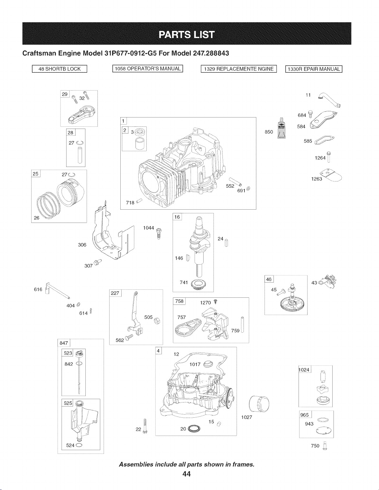
Craftsman Engine Model 31P677=0912=G5 For Model 247.288843
I 48 SHORTB LOCK I 110580PERATOR'SMANUAL] 11329REPLACEMENTENGINEI 11330REPAIRMANUALI
::..................,¢.32 . ::
....
26
306
307 _
616
404 _
614
552
691 (_,
1044 !_
: J
146rb1-/
7414 _ _
7s8i 1270
757
759 i
85O
11
584684: -_
585
1264 :_i
524 C>
D
22
1o27
Assemblies include all parts shown in frames.
44
750 :i

Craftsman Engine Model 31P677=0912=G5 For Model 247.288843
635
306
1029
1022
35
51
883
1026 z_ _'
1026A _ _¢_
45
914 _
85O
54
654
Assemblies include all parts shown in frames.
45
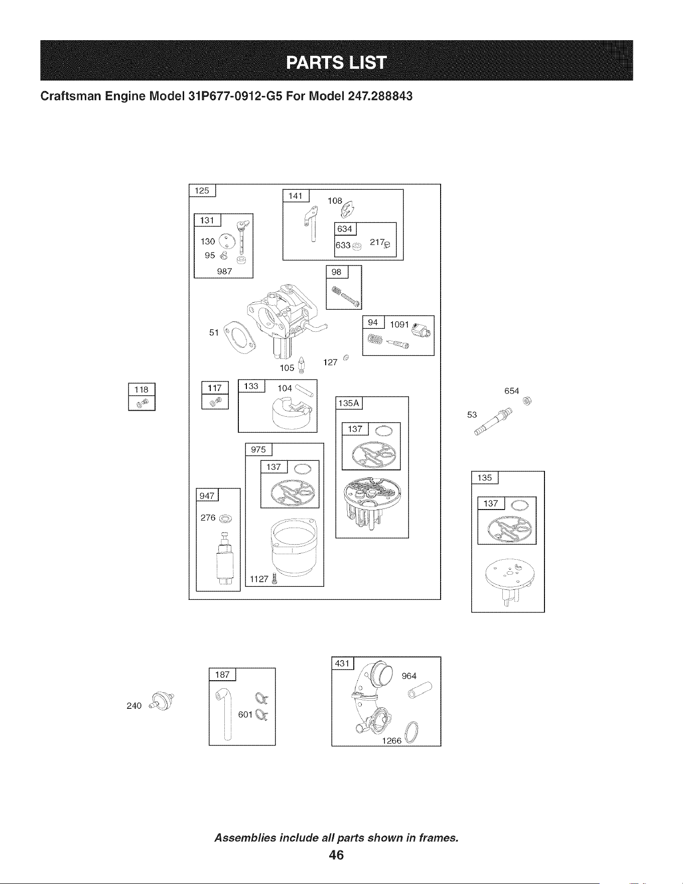
Craftsman Engine Model 31P677-0912-G5 For Model 247.288843
13o I
987 ::_1
51
276 _9)
108_
217_
1091
._- .... ._s/_
1127 _} "
654
37 [ S°"_
24O
601 _,_
964
Assemblies include all parts shown in frames.
46
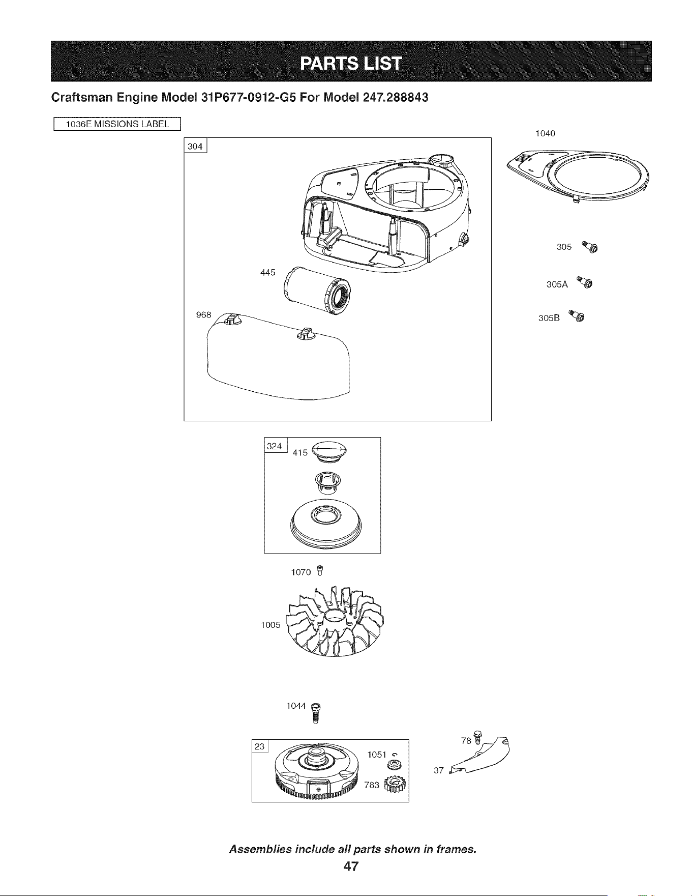
Craftsman Engine IViodel 31P677=0912=G5 For IViodel 247.288843
I 1036E MISSIONS LABEL
1040
305 %
305A '_
305B
1070
1005
1044
_ 1051
®
783@
Assemblies include all parts shown in frames.
47
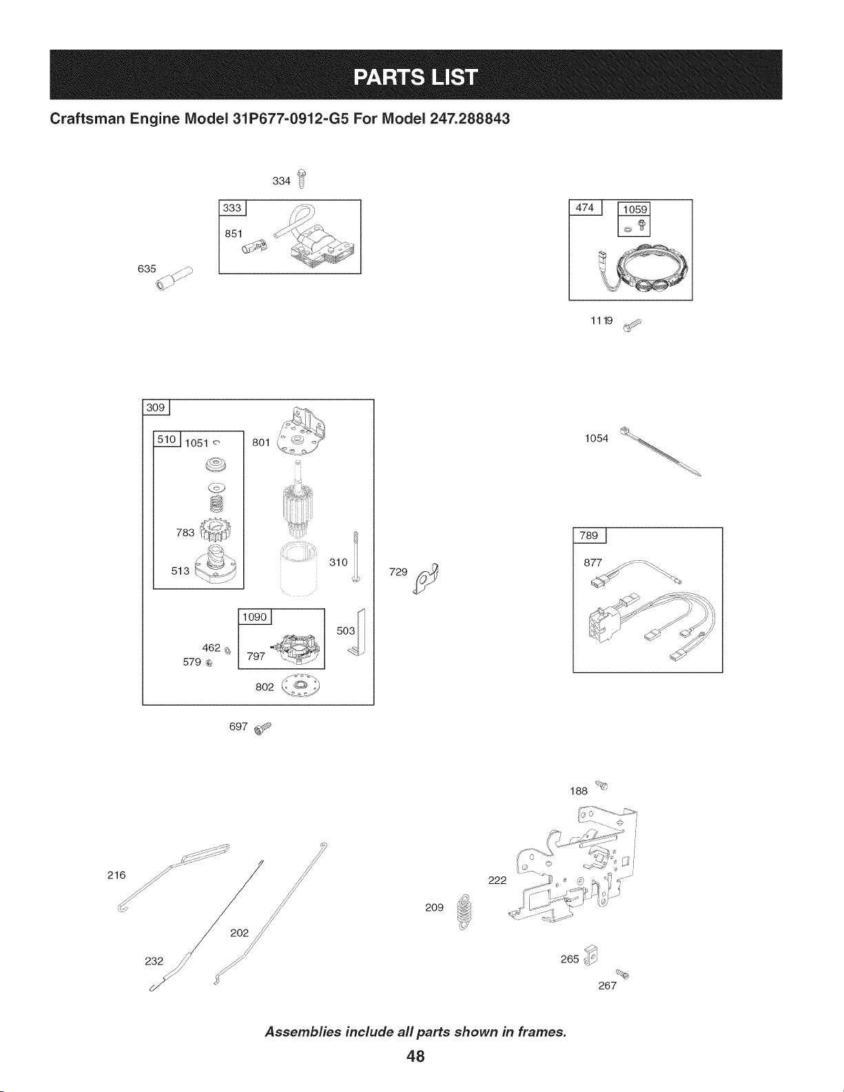
Craftsman Engine Model 31P677=0912=G5 For Model 247.288843
1119
783
513
8Ol_ _,_,y
t
802 K__,_,,:.Y
310
i,
877 _-.< :::-_.\
697 _-_
188 '_@
209
©
222
232
265 d_
%
267
Assemblies include all parts shown in frames.
48
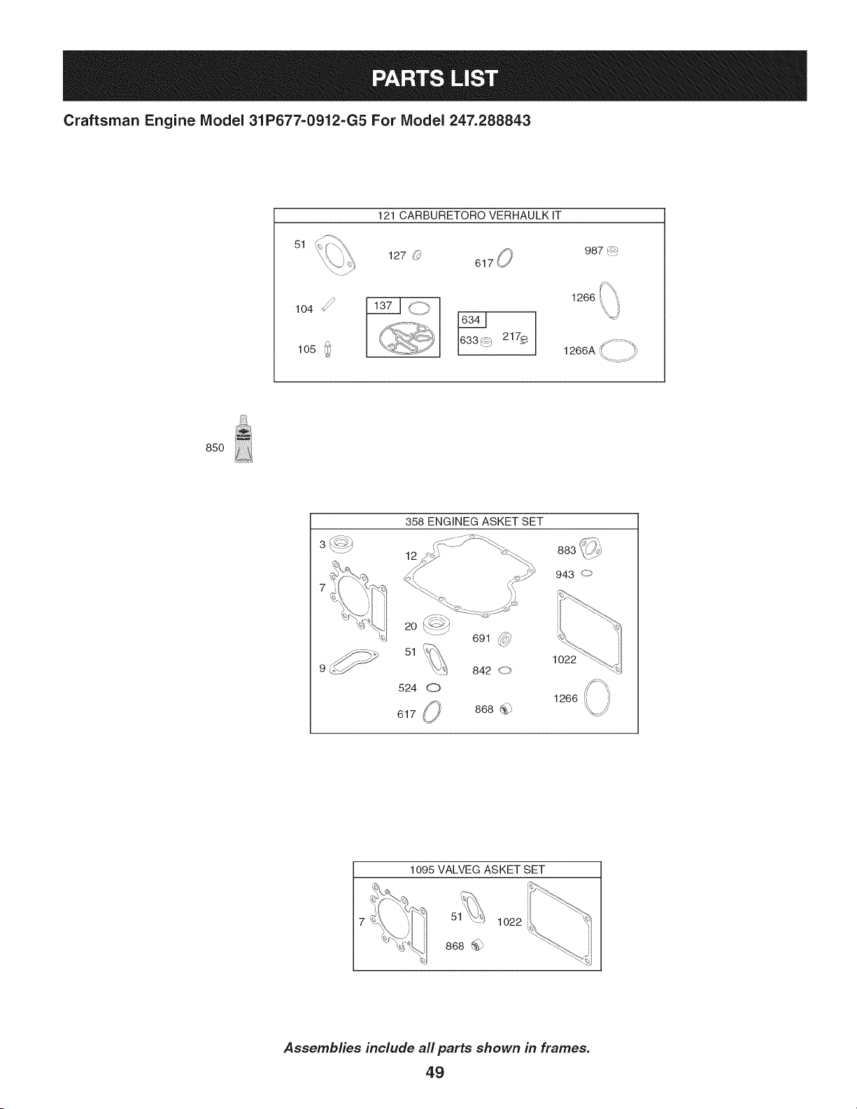
Craftsman Engine Model 31P677=0912=G5 For Model 247.288843
51
j
121 CARBURETORO VERHAULK IT
127 _
987(_
1266A _<=-)
85O
\ /
358 ENGINEG ASKET SET
12
943 <_
1095 VALVEG ASKET SET
5" 1022
868 _
Assemblies include all parts shown in frames.
49
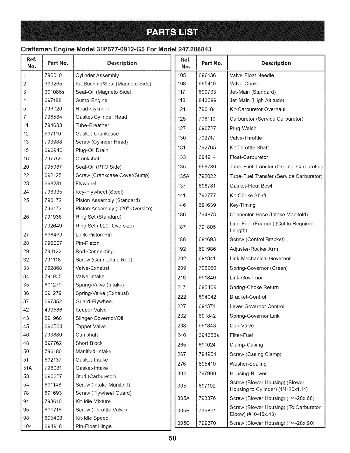
Craftsman Engine IViodel 31P677=0912=G5 For IViodel 247.288843
Ref,
No,
1 796010
2 399265
3 391086s
4 697188
5 796026
7 796584
11 794683
12 697110
13 793988
15 690946
16 797759
20 795387
22 692125
23 698281
24 796335
25 796172
796173
26 791936
792649
27 698469
28 796007
29 794122
32 791118
33 792868
34 791935
35 691279
36 691279
37 697352
42 499586
43 691968
45 690564
46 793880
48 697762
50 796180
51 692137
51A 796081
53 690227
54 691148
78 691693
94 793610
95 690718
98 695408
104 694918
Part No. Description
Cylinder Assembly
Kit-Bushing/Seal (Magneto Side)
Seal-Oil (Magneto Side)
Sump-Engine
Head-Cylinder
Gasket-Cylinder Head
Tube-Breather
Gasket-Crankcase
Screw (Cylinder Head)
Plug-Oil Drain
Crankshaft
Seal-Oil (PTO Side)
Screw (Crankcase Cover/Sump)
Flywheel
Key-Flywheel (Steel)
Piston Assembly (Standard)
Piston Assembly (.020" Oversize)
Ring Set (Standard)
Ring Set (.020" Oversize)
Lock-Piston Pin
Pin-Piston
Rod-Connecting
Screw (Connecting Rod)
Valve- Exhaust
Valve-Intake
Spring-Valve (Intake)
Spring-Valve (Exhaust)
Guard-Flywheel
Keeper-Valve
Slinger-Governor/Oil
Tappet-Valve
Camshaft
Short Block
Manifold-Intake
Gasket-Intake
Gasket-Intake
Stud (Carburetor)
Screw (Intake Manifold)
Screw (Flywheel Guard)
Kit-Idle Mixture
Screw (Throttle Valve)
Kit-Idle Speed
Pin-Float Hinge
I
Ref.
I Part No.
No,
I
105 696136
108 695419
117 699733
118 843099
121 796184
125 796110
127 690727
130 792747
131 792765
133 694914
135 698780
135A 792022
137 698781
141 792777
146 691639
186 794873
187 791805
188 691693
192 691986
202 691841
209 796260
216 691840
217 695409
222 694042
227 691374
232 691842
238 691843
240 394358s
265 691024
267 794904
276 695410
304 797900
305 697102
305A 793376
305B 795891
305C 799370
Description
Valve-Float Needle
Valve-Choke
Jet-Main (Standard)
Jet-Main (High Altitude)
Kit-Carburetor Overhaul
Carburetor (Service Carburetor)
Plug-Welch
Valve-Throttle
Kit-Throttle Shaft
Float-Carburetor
Tube-Fuel Transfer (Original Carburetor)
Tube-Fuel Transfer (Service Carburetor)
Gasket-Float Bowl
Kit-Choke Shaft
Key-Timing
Connector-Hose (Intake Manifold)
Line-Fuel (Formed) (Cut to Required
Length)
Screw (Control Bracket)
Adjuster-Rocker Arm
Link-Mechanical Governor
Spring-Governor (Green)
Link-Governor
Spring-Choke Return
Bracket-Control
Lever-Governor Control
Spring-Governor Link
Cap-Valve
Fitter-Fuel
Clamp-Casing
Screw (Casing Clamp)
Washer-Sealing
Housing-Blower
Screw (Blower Housing) (Blower
Housing to Cylinder) (1/4-20xl .14)
Screw (Blower Housing) (1/4-20x.68)
Screw (Blower Housing) (To Carburetor
Elbow) (#10-16x.43)
Screw (Blower Housing) (1/4-20x.90)
5O
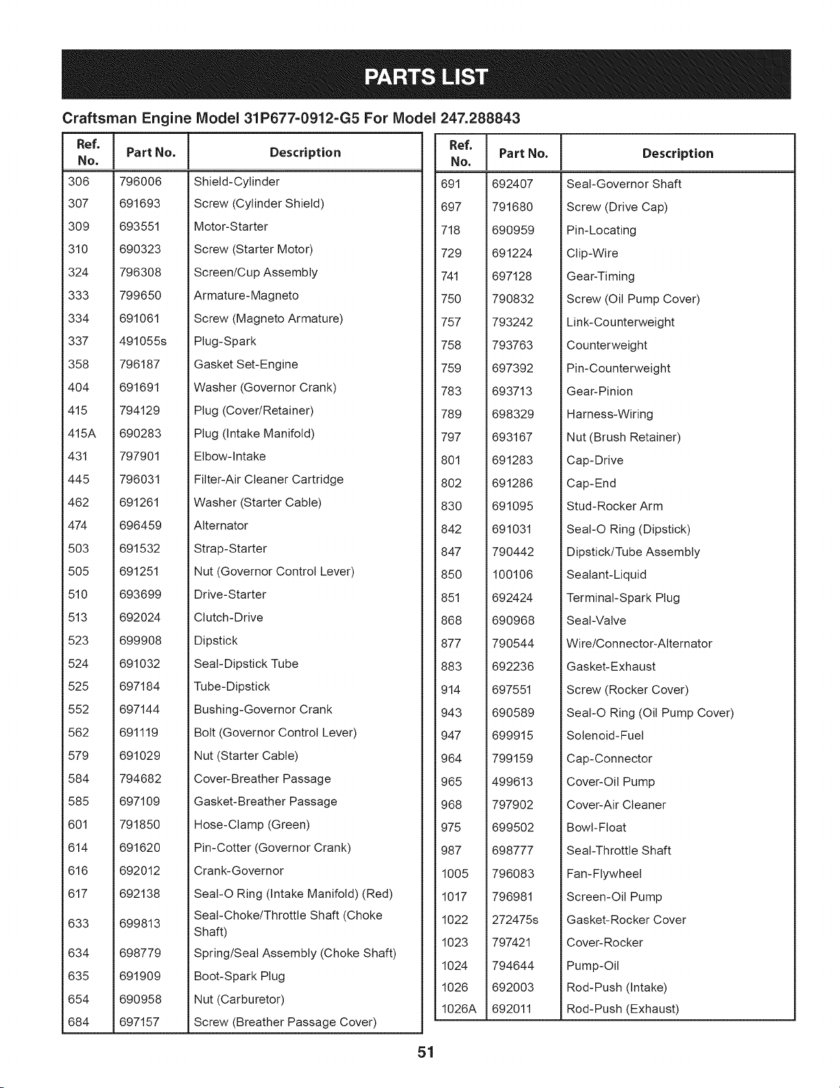
Craftsman Engine IViodel 31P677=0912=G5 For IViodel 247.288843
I
Ref.
I Part No.
No,
I
306 796006
307 691693
309 693551
310 690323
324 796308
333 799650
334 691061
337 491055s
358 796187
404 691691
415 794129
415A 690283
431 797901
445 796031
462 691261
474 696459
503 691532
505 691251
510 693699
513 692024
523 699908
524 691032
525 697184
552 697144
562 691119
579 691029
584 794682
585 697109
601 791850
614 691620
616 692012
617 692138
633 699813
634 698779
635 691909
654 690958
684 697157
Description
Shield-Cylinder
Screw (Cylinder Shield)
Motor-Starter
Screw (Starter Motor)
Screen/Cup Assembly
Armature-Magneto
Screw (Magneto Armature)
Plug-Spark
Gasket Set-Engine
Washer (Governor Crank)
Plug (Cover/Retainer)
Plug (Intake Manifold)
Elbow-Intake
Fitter-Air Cleaner Cartridge
Washer (Starter Cable)
Alternator
Strap-Starter
Nut (Governor Control Lever)
Drive-Starter
Clutch-Drive
Dipstick
Seal-Dipstick Tube
Tube-Dipstick
Bushing-Governor Crank
Bolt (Governor Control Lever)
Nut (Starter Cable)
Cover-Breather Passage
Gasket-Breather Passage
Hose-Clamp (Green)
Pin-Cotter (Governor Crank)
Crank-Governor
SeaI-O Ring (Intake Manifold) (Red)
Seal-Choke/Throttle Shaft (Choke
Shaft)
Spring/Seal Assembly (Choke Shaft)
Boot-Spark Plug
Nut (Carburetor)
Screw (Breather Passage Cover)
Ref.
No,
691 692407
697 791680
718 690959
729 691224
741 697128
750 790832
757 793242
758 793763
759 697392
783 693713
789 698329
797 693167
801 691283
802 691286
830 691095
842 691031
847 790442
850 100106
851 692424
868 690968
877 790544
883 692236
914 697551
943 690589
947 699915
964 799159
965 499613
968 797902
975 699502
987 698777
1005 796083
1017 796981
1022 272475s
1023 797421
1024 794644
1026 692003
1026A 692011
Part No. Description
Seal-Governor Shaft
Screw (Drive Cap)
Pin-Locating
Clip-Wire
Gear-Timing
Screw (Oil Pump Cover)
Link-Counterweight
Counterweight
Pin-Counterweight
Gear-Pinion
Harness-Wiring
Nut (Brush Retainer)
Cap-Drive
Cap-End
Stud- Rocker Arm
SeaI-O Ring (Dipstick)
Dipstick/Tube Assembly
Sealant-Liquid
Terminal-Spark Plug
Seal-Valve
Wire/Connector-Alternator
Gasket-Exhaust
Screw (Rocker Cover)
SeaI-O Ring (Oil Pump Cover)
Solenoid-Fuel
Cap-Connector
Cover-Oil Pump
Cover-Air Cleaner
Bowl-Float
Seal-Throttle Shaft
Fan-Flywheel
Screen-Oil Pump
Gasket-Rocker Cover
Cover- Rocker
Pump-Oil
Rod-Push (Intake)
Rod-Push (Exhaust)
51
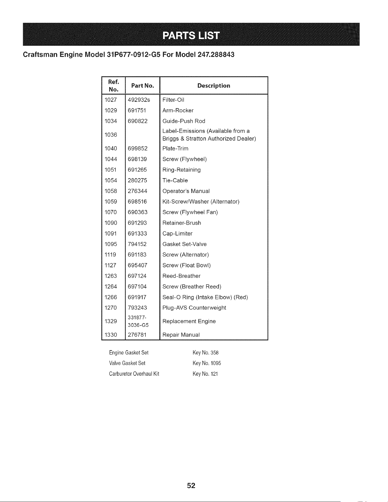
Craftsman Engine IViodel 31P677=0912=G5 For IViodel 247.288843
Ref, I
No,
1027
1029
1034
1036
Part No. Description
492932s
691751
690822
1040 699852
1044 698139
1051 691265
1054 280275
1058 276344
1059 698516
1070 690363
1090 691293
1091 691333
1095 794152
1119 691183
1127 695407
1263 697124
1264 697104
1266 691917
1270 793243
331877-
1329
3036-G5
1330 276781
Fitter-Oil
Arm-Rocker
Guide-Push Rod
Label-Emissions (Available from a
Briggs & Stratton Authorized Dealer)
Plate-Trim
Screw (Flywheel)
Ring-Retaining
Tie-Cable
Operator's Manual
Kit-Screw/Washer (Alternator)
Screw (Flywheel Fan)
Retainer-Brush
Cap-Limiter
Gasket Set-Valve
Screw (Alternator)
Screw (Float Bowl)
Reed- Breather
Screw (Breather Reed)
Seal-O Ring (Intake Elbow) (Red)
PIug-AVS Counterweight
Replacement Engine
Repair Manual
EngineGasketSet Key No.358
ValveGasketSet Key No.1095
CarburetorOverhaulKit Key No.121
52

Esta pagina se dej6 intencionalmente en blanco. Utilice esta pagina para tomar notas acerca de su tractor.
53

Esta pagina se dej6 intencionalmente en blanco. Utilice esta pagina para tomar notas acerca de su tractor.
54
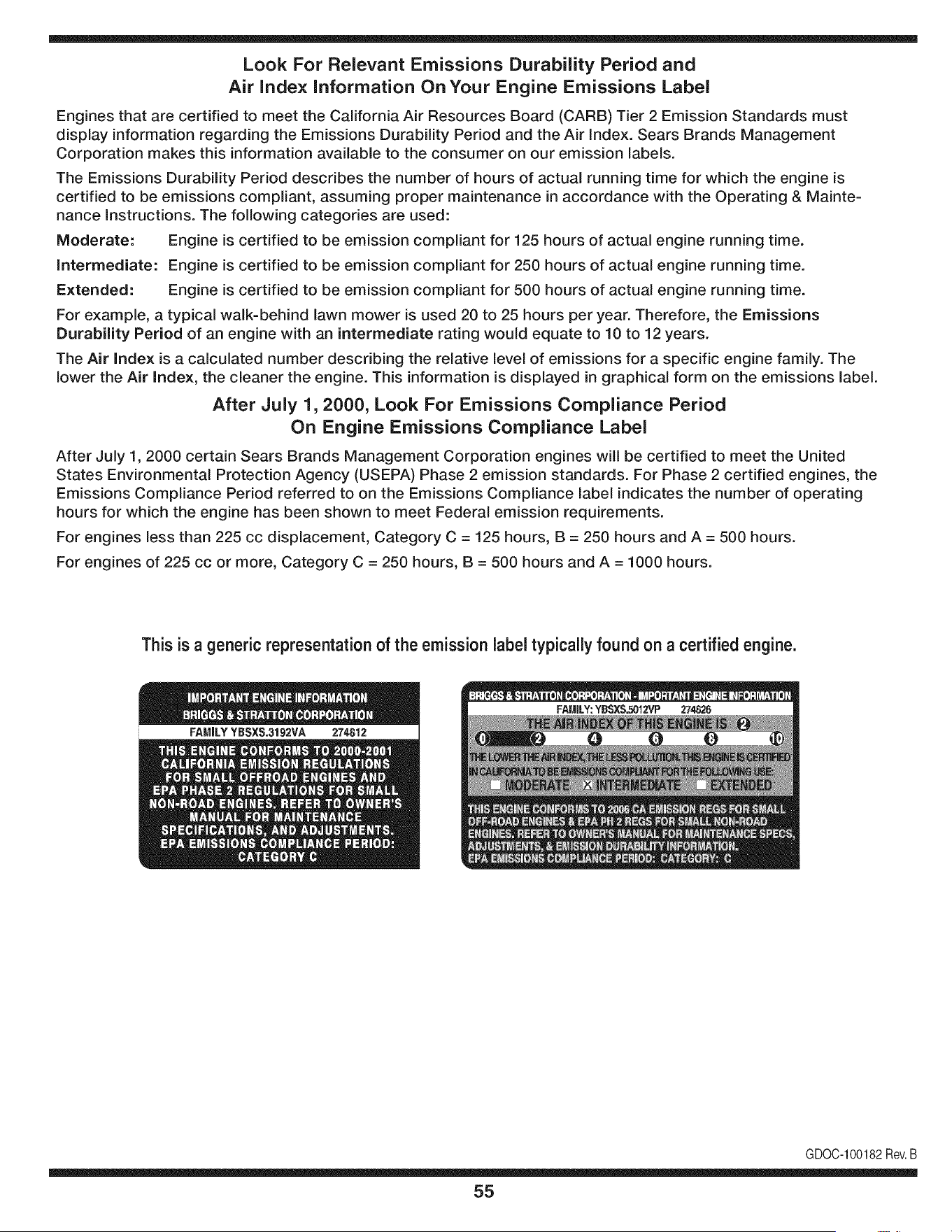
Look For Relevant Emissions Durability Period and
Air index information On Your Engine Emissions Label
Engines that are certified to meet the California Air Resources Board (CARB) Tier 2 Emission Standards must
display information regarding the Emissions Durability Period and the Air Index. Sears Brands Management
Corporation makes this information available to the consumer on our emission labels.
The Emissions Durability Period describes the number of hours of actual running time for which the engine is
certified to be emissions compliant, assuming proper maintenance in accordance with the Operating & Mainte-
nance Instructions. The following categories are used:
Moderate: Engine is certified to be emission compliant for 125 hours of actual engine running time.
Intermediate: Engine is certified to be emission compliant for 250 hours of actual engine running time.
Extended: Engine is certified to be emission compliant for 500 hours of actual engine running time.
For example, a typical walk-behind lawn mower is used 20 to 25 hours per year. Therefore, the Emissions
Durability Period of an engine with an intermediate rating would equate to 10 to 12 years.
The Air index is a calculated number describing the relative level of emissions for a specific engine family. The
lower the Air Index, the cleaner the engine. This information is displayed in graphical form on the emissions label.
After July 1,2000, Look For Emissions Compliance Period
On Engine Emissions Compliance Label
After July 1, 2000 certain Sears Brands Management Corporation engines will be certified to meet the United
States Environmental Protection Agency (USEPA) Phase 2 emission standards. For Phase 2 certified engines, the
Emissions Compliance Period referred to on the Emissions Compliance label indicates the number of operating
hours for which the engine has been shown to meet Federal emission requirements.
For engines less than 225 cc displacement, Category C = 125 hours, B = 250 hours and A = 500 hours.
For engines of 225 cc or more, Category C = 250 hours, B = 500 hours and A = 1000 hours.
This is a generic representation of the emission label typically found on a certified engine.
FAMILYYBSXS.3192VA 274812
GDOC-100182Rev.B
55
(Thispageapplicablein the U.S.A.and Canadaonly.)
Sears Brands Management Corporation (Sears), the California Air Resources Board (CARD)
and the United States Environmental Protection Agency (U.S. EPA)
Emission Control System Warranty Statement (Owner's Defect Warranty Rights and Obligations)
EMISSIONCONTROLWARRANTYCOVERAGEISAPPLICABLETOCERTI-
FIEDENGINESPURCHASEDIN CALIFORNIAIN1995ANDTHEREAF-
TER,WHICHARE USEDINCALIFORNIA,ANDTOCERTIFIEDMODEL
California and United States Emission
The CaliforniaAir ResourcesBoard(CARD),U.S.EPAand Searsare pleased
to explainthe EmissionControlSystemWarrantyon your modelyear2000and
latersmalloff-roadengine(SORE).In California,newsmall off-roadengines
mustbe designed,builtand equippedto meetthe State'sstringentanti-smog
standards.Elsewherein theUnitedStates, newnon-road,spark-ignition
enginescertifiedfor modelyear 1997and latermustmeetsimilar standardsset
forth bythe U.S.EPA.Sears mustwarrantthe emissioncontrol systemon your
YEAR 1997AND LATERENGINESWHICHARE PURCHASEDAND USED
ELSEWHEREIN THE UNITEDSTATES(ANDAFTERJANUARY1,2001 IN
CANADA).
Control Defects Warranty Statement
enginefor theperiodsoftime listedbelow,providedtherehas been noabuse,
neglector impropermaintenanceof your smalloff-roadengine.Youremis-
sion controlsystemincludespartssuch as thecarburetor,air cleaner,ignition
system,mufflerand catalyticconverter.Also includedmaybe connectorsand
otheremissionrelatedassemblies.Wherea warrantableconditionexists,Sears
will repairyour smalloff-roadengineat no costto you includingdiagnosis,parts
and labor.
Sears Emission Control Defects Warranty Coverage
Smalloff-roadenginesarewarrantedrelativeto emissioncontrolpartsdefects
fora periodof one year,subjectto provisionsset forth below.Ifany covered
Owner's Warranty
Asthe smalloff-roadengine owner,you are responsiblefor the performanceof
therequiredmaintenancelistedin yourOperatingand MaintenanceInstruc-
tions.Searsrecommendsthatyou retain all yourreceiptscoveringmaintenance
on yoursmalloff-roadengine,but Sears cannotdenywarrantysolelyfor the
lackof receiptsorfor yourfailureto ensuretheperformanceof all scheduled
maintenance.As the smalloff-roadengineowner,you shouldhoweverbe
awarethat Searsmay denyyou warrantycoverageifyour smalloff-roadengine
ora part hasfailed dueto abuse,neglect,impropermaintenanceor unap-
parton yourengineis defective,the part will be repairedor replacedbySears.
Responsibilities
provedmodifications.Youare responsiblefor presentingyour smalloff-road
engineto an AuthorizedSearsServiceDealeras soonas a problemexists.The
undisputedwarrantyrepairsshouldbe completedina reasonableamountof
time,notto exceed30days. Ifyou haveany questionsregardingyourwarranty
rightsand responsibilities,you shouldcontacta SearsService Representative
at 1-800-469-4663.The emissionwarrantyis a defectswarranty.Defectsare
judgedon normalengineperformance.The warrantyis notrelatedto an in-use
emissiontest.
Sears Emission Control Defects Warranty Provisions
ThefollowingarespecificprovisionsrelativetoyourEmissionControlDefectsWarrantyCoverage.ItisinadditiontotheSearsenginewarrantyfornon-regulated
enginesfoundin the Operatingand MaintenanceInstructions.
1. WarrantedParts
Coverageunderthis warrantyextendsonly to the parts listedbelow (the
emissioncontrolsystemsparts)to the extentthese partswere presenton
theengine purchased.
a. FuelMeteringSystem
• Cold start enrichmentsystem
• Carburetorand internalparts
• FuelPump
b. Air lnduction System
• Air cleaner
• Intakemanifold
c. IgnitionSystem
• Spark plug(s)
• Magnetoignitionsystem
d. CatalystSystem
• Catalyticconverter
• Exhaustmanifold
• Air injectionsystemor pulsevalve
e. MiscellaneousItemsUsedin AboveSystems
• Vacuum,temperature,position,timesensitivevalves
andswitches
• Connectorsandassemblies
2. Lengthof Coverage
Searswarrantsto the initialownerand eachsubsequentpurchaserthat
theWarrantedPartsshallbefree from defects in materialsandworkman-
shipwhich causedthe failure of the WarrantedPartsfor a periodof one
yearfrom the datethe engineis deliveredto a retailpurchaser.
3. NoCharge
Repairor replacementof anyWarrantedPartwill beperformedat no
chargeto the owner,includingdiagnosticlabor whichleadsto the
determinationthata WarrantedPartis defective,if the diagnosticwork is
performedat an AuthorizedSears ServiceDealer.Foremissionswarranty
servicecontact yournearestAuthorizedSears ServiceDealeras listed in
the "YellowPages"under"Engines,Gasoline,""GasolineEngines,""Lawn
Mowers,"or similar category.
4. Claimsand CoverageExclusions
Warrantyclaimsshall be filed in accordancewiththe provisionsof the
Sears EngineWarrantyPolicy.Warrantycoverageshall be excludedfor
failuresof WarrantedPartswhichare not original Sears partsor because
of abuse, neglector impropermaintenanceas setforth inthe Sears
EngineWarrantyPolicy.Searsis not liableto coverfailuresof Warranted
Partscausedby the use of add-on, non-original,or modifiedparts.
5. Maintenance
Any WarrantedPart whichis notscheduledfor replacementas required
maintenanceor whichis scheduledonly for regularinspectionto the effect
of "repairor replace as necessary"shallbe warrantedas to defectsfor the
warrantyperiod.Any WarrantedPartwhich is scheduledfor replacement
as requiredmaintenanceshallbe warrantedas to defectsonly forthe
periodof time upto the firstscheduledreplacementfor that part. Any
replacementpart that is equivalentin performanceand durabilitymay
be usedin the performanceof any maintenanceor repairs.The owneris
responsibleforthe performanceof all requiredmaintenance,as definedin
the SearsOperatingand MaintenanceInstructions.
6. ConsequentialCoverage
Coveragehereundershallextendto the failure of any enginecomponents
caused bythe failureof any WarrantedPartstill underwarranty.
Inthe USAandCanada,a 24 hour hot line, 1-800-469-4663,has a menuof pre-recordedmessagesofferingyou enginemaintenanceinformation.
GDOC-100188Rev.B
56
FEDERALand/or CALIFORNIAEMISSIONCONTROLWARRANTYSTATEMENT
YOURWARRANTYRIGHTSANDOBLIGATIONS
MTD Consumer Group Inc, the United States Environmental Protection Agency (EPA), and, for those products certified for sale in the state of
California, the California Air Resources Board (CARB) are pleased to explain the emission (evaporative and/or exhaust) control system (ECS)
warranty on your outdoor 2006 and later small off-road spark-ignited engine and equipment (outdoor equipment engine) In California, new
outdoor equipment engines must be designed, built and equipped to meet the State's stringent anti-smog standards (in other states, 1997 and
later model year equipment must be designed, built, and equipped to meet the U.S. EPA small off-road, spark ignition engine regulations. MTD
Consumer Group Inc must warrant the ECSon your outdoor equipment engine for the period of time listed below provided there has been no
abuse, neglect or improper maintenance of outdoor equipment engine.
Your ECS may include parts such as the carburetor, fuel-injection system, the ignition system, catalytic converter, fuel tanks, fuel lines, fuel caps,
valves, canisters, filters, vapor hoses, clamps, connectors, and other associated emission-related components.
Where a warrantable condition exists, MTD Consumer Group Inc will repair your outdoor equipment engine at no cost to you including
diagnosis, parts and labor.
MANUFACTURER'SWARRANTYCOVERAGE:
This emission control system is warranted for two years. If any emission-related part on your outdoor equipment engine is defective, the part
will be repaired or replaced by MTD CONSUMER GROUP INC.
OWNER'SWARRANTYRESPONSIBILITIES:
As the outdoor equipment engine owner, you are responsible for performance of the required maintenance listed in your owner's manual. MTD
Consumer Group Inc recommends that you retain all receipts covering maintenance on your outdoor equipment engine, but MTD Consumer
Group Inc cannot deny warranty solely for the lack of receipts.
As the outdoor equipment engine owner, you should however be aware that MTD Consumer Group Inc may deny you warranty coverage if
your outdoor equipment engine or a part has failed due to abuse, neglect, or improper maintenance or unapproved modifications.
You are responsible for presenting your outdoor equipment engine to MTD Consumer Group Inc's distribution center or service center as soon
as the problem exists. The warranty repairs should be completed in a reasonable amount of time, not to exceed 30 days. If you have a question
regarding your warranty coverage, you should contact the MTD Consumer Group Inc Service Department at 1-800-800-7310 or via email at
http://su pport.mtd prod ucts.com
GENERALEMISSIONSWARRANTYCOVERAGE:
MTD Consumer Group Inc warrants to the ultimate purchaser and each subsequent purchaser that the outdoor equipment engine is: Designed,
built and equipped so as to conform with all applicable regulations; and free from defects in materials and workmanship that cause the failure
of a wa rranted part to be identical in all material respects to that part as described in MTD Consumer Group Inc's application for certification.
The warranty period begins on the date the outdoor equipment engine is delivered to an ultimate purchaser or first placed into service. The
warranty period is two years.
Subject to certain conditions and exclusions as stated below, the warranty on emission-related parts is as follows:
1. Any warranted part that is not scheduled for replacement as required maintenance in the written instructions supplied, is warranted for
the warranty period stated above. If the part fails during the period of warranty coverage, the part will be repaired or replaced by MTD
Consumer Group Inc according to subsection (4) below. Any such part repaired or replaced under warranty will be warranted for the
remainder of the period.
2. Any warranted part that is scheduled only for regular inspection in the written instructions supplied is warranted for the warranty period
stated above. Any such part repaired or replaced under warranty will be warranted for the remaining warranty period.
3. Any warranted part that is scheduled for replacement as required maintenance in the written instructions supplied is warranted for the
period of time before the first scheduled replacement date for that part. If the part fails before the first scheduled replacement, the part
will be repaired or replaced by MTD Consumer Group Inc according to subsection (4) below. Any such part repaired or replaced under
warranty will be warranted for the remainder of the period prior to the first scheduled replacement point for the part.
Repair or replacement of any warranted part under the warranty provisions herein must be performed at a warranty station at no charge
to the owner.
4.
5. Notwithstanding the provisions herein, warranty services or repairs will be provided at all of our distribution centers that are franchised to
service the subject engines or equipment.
6. The outdoor equipment engine owner will not be charged for diagnostic labor that is directly associated with diagnosis of a defective,
emission-related warranted part, provided that such diagnostic work is performed at a warranty station.
7. MTD Consumer Group Inc is liable for damages to other engine or equipment components proximately caused by a failure under
warranty of any warranted part.
8. Throughout the off-road engine and equipment warranty period stated above, MTD Consumer Group Inc will maintain a supply of
warranted parts sufficient to meet the expected demand for such parts.
9. Any replacement part may be used in the performance of any warranty maintenance or repairs and must be provided without charge to
the owner. Such use will not reduce the warranty obligations of MTD Consumer Group Inc.
10. Add-onormodifiedpartsthatarenotexemptedbytheAirResourcesBoardmaynotbeused.Theuseofanynon-exemptedadd-onor
modifiedpartsbytheultimatepurchaserwillbegroundsfordisallowingawarrantyclaims.MTDConsumerGroupIncwillnotbeliableto
warrantfailuresofwarrantedpartscausedbytheuseofanon-exemptedadd-onormodifiedpart.
WARRANTEDPARTS:
The repair or replacement of any warranted part otherwise eligible for warranty coverage may be excluded from such warranty coverage if
MTD Consumer Group Inc demonstrates that the outdoor equipment engine has been abused, neglected, or improperly maintained, and that
such abuse, neglect, or improper maintenance was the direct cause of the need for repair or replacement of the part. That notwithstanding,
any adjustment of a component that has a factory installed, and properly operating, adjustment limiting device is still eligible for warranty
coverage. Further, the coverage under this warranty extends only to parts that were present on the off-road engine and equipment purchased.
The following emission warranty parts are covered (if applicable):
1. Fuel Metering System
Cold start enrichment system (soft choke)
Carburetor and internal parts (or fuel injection system)
Fuel pump
Fuel tank
2. Air Induction System
Air cleaner
Intake manifold
3. Ignition System
Spark plug(s)
Magneto ignition system
4. Exhaust System
Catalytic converter
SAI (Reed valve)
5. Miscellaneous Items Used in Above System
Vacuum, temperature, position, time sensitive valves and switches
Connectors and assemblies
6. Evaporative Control
Fuel hose
Fuel hose clamps
Tethered fuel cap
Carbon canister
• Vapor lines
GDOG100223Rev.A

Congratulations on making a smart purchase. Your new Craftsman® product is designed and
manufactured for years of dependable operation. But like all products, it may require repair
from time to time. That's when having a Repair Protection Agreement can save you money and
aggravation.
Here's what the Repair Protection Agreement* includes:
[] Expert service by our 10,000 professional repair specialists
[] Unlimited service and no charge for parts and labor on all covered repairs
[] Product replacement up to $1500 if your covered product can't be fixed
[] Discount of 25% from regular price of service and related installed parts not covered by the
agreement; also, 25% off regular price of preventive maintenance check
[] Fast help by phone - we call it Rapid Resolution - phone support from a Sears representative.
Think of us as a "talking owner's manual."
Once you purchase the Repair Protection Agreement, a simple phone call is all that it takes for you
to schedule service. You can call anytime day or night, or schedule a service appointment online.
The Repair Protection Agreement is a risk-free purchase. If you cancel for any reason during the
product warranty period, we will provide a full refund. Or, a prorated refund anytime after the
product warranty period expires. Purchase your Repair Protection Agreement today!
Some limitations and exclusions apply. For prices and additional information in the U.S.A.
call 1=800=827=6655.
*Coverage in Canada varies on some items. For full details call Sears Canada at 1=800=361=
6665.
Sears Installation Service
For Sears professional installation of home appliances, garage door openers, water heaters, and
other major home items, in the U.S.A. or Canada call 1=800=4=MY=HOME®.
59
Operaci6n segura Pr,_cticas .......... Paginas 61
Asamblea ........................... Page 67
Operaci6n de ...................... Paginas 69
De Servicio y Mantenimiento de ....... Paginas 76
Fuera de temporada de almacenamiento .. Page 85
Soluci6n de problemas ................ Page 86
Etiquetas ................................. 28
Lista de piezas ..................... Paginas 30
Reparaci6n de Acuerdo de Protecci6n .... Page 91
Servicio de nOmeros ............ atrasados Page
CRAFTSMAN GARANT{A COMPLETA
DURANTEdosa_osdesdela fechadecompra,todaslaspartesde nofungiblesdeesteequipode equitaci6nestangarantizadascontracualquier
defectode materialo manodeobra.Unaparteno fungiblesdefectuosarecibir_a domicilioreparaci6nola sustituci6nsila reparaci6nnoest_disponible.
GARANT{ALIMITADADE LABATER{A
POR90 diasdesde lafechade compra,la bateria(unapiezaconsumible)de este equipode conducci6nesta garantizadacontracualquier
defectode materialo manodeobra. Unabaterianuevase suministrar_gratuitamente.Ustedes responsablepor elcostode manodeobra de
instalaci6nde la bateria.
GARANT{ALIMITADAADICIONAL
Enlas siguientesgaranfiasadicionales,ustedes responsableporel costodemanode obrade instalaci6nde la partedespu_sdelsegundoaSo
desdela fecha de compra.
DURANTEcincoaSosdesdela fecha de compra,el marcodeeste equipode conducci6nest&garantizadocontracualquierdefectode material
o manode obra.Se suministrarAun nuevomarcodeformagratuita.
DURANTEdiezaSosdesde lafechadecompra,el ejedelanterodeesteequipode conducci6nest&garantizadocontracualquierdefectode
materialo manodeobra. Sesuministrar&unnuevoeje delanterogratuitamente.
PARAmientrases utilizadopor el propietariooriginaldespuesdel d_cimoaSode lafechadecompra,el eje hierrofundidofrontal(si esta
equipado)deeste equipodeconducci6nest&garantizadocontracualquierdefectode materialo manode obra.Concomprobantede compra,
se suministrar&un nuevoejedelanterodefundici6nde hierrodeformagratuita.
SERVlCIODEGARANT{A
Paradetallesde lacoberturade garantiaobtenerla reparaci6no reemplazo,Ilameal 1-800-659-5917o visite elsitioweb:www.craftsman.com
Entodosloscasos,sisepartede la reparaci6no reemplazoesimposible,elequipodeequitaci6nsereemplazar&gratuitamenteconelmismooequivalente.
Todoslosde la anteriorgarantiaesnulasiseutilizaesteequipode conducci6nmientrasqueproporcionaservicioscomercialeso Sialquilaaotrapersona.
Estagaranfiacubresolamentedefectosen materialy manode obra. Coberturade la garanfianoincluye:
• Piezasfungibles(exceptola bateria)quepuedengastarsepor el uso normaldentrodel periodode garanfia,incluyendoperono limitadoa
cuchillas,bujias,filtrosde aire,correasy filtros deaceite.
• Serviciode mantenimientoestandar,cambiosde aceiteo puestasa punto.
• NeumAticode repuestoo reparaci6ncausadasporpinchazosde objetosexternos,talescomoclavos,espinas,toconeso vidrio.
NeumAticoo ruedade repuestoo reparaci6nresultantesdeldesgastenormal,accidente,o funcionamientoincorrectoo mantenimiento.
• Reparacionesnecesariasdebidoa abusodel operador,incluyendoperono limitadoa daSoscausadosporobjetosm&sall&de la capacidad
de losequiposde conducci6nde remolque,afectarobjetosquedoblanel marco,el eje o el cig(JeSalo over-speedingel motor.
• Reparacionesnecesariasdebidoa la negligenciadeloperador,incluyendoperono limitadoa, daSosel_ctricosy mecanicoscausados
poralmacenamientoinadecuado,no usarel grado adecuadoy la cantidadde aceitede motor,no mantenerla cubiertalibrede residuos
inflamables,o faltade mantenimientodelequipode equitaci6nsegQnlas instruccionescontenidasenel manualdeloperador.
Motor(sistemadecombustible)limpiezao reparacionesocasionadospor el combustibledeterminadoestarcontaminadosuoxidan
(obsoletos).Engeneral,el combustibledebeutilizarsedentrode30 diasde la fechade compra.
• Eldeterioronormaly el desgastedelos acabadosexteriores,o reemplazodela etiquetadel producto.
Estagaranfiale otorgaderechoslegalesespecificos,y ustedtambi_npuedetenerotrosderechosquevariandeestadoa estado.
Sears Brands Management Co_)oration, HoffmanEstates, IL 60179
N_mero de modelo ..........................................................
Aceitedel motor: SAE30 N_mero de serie ..............................................................
Combustible: Gasolinasinplomo Fechade compra .............................................................
Bujia: Champion@RC12YC RegistrearribaelnQmerodelmodelo,elnQmerodeserieylafechadecompra
© Sears Brands,LLC
60
Lapresenciade este sirnboloindicaque setratade instrucciones
irnportantesde seguridadquese debenrespetarparaevitar
poneren peligrosu seguridadpersonaly/o materialy lade otras
personas.Leay siga todaslas instruccionesde este manualantes
de poneren funcionarnientoestarn_.quina.Si no respetaestas
instruccionespodriaprovocarlesionespersonales.Cuandoveaeste
sirnbolo,ipresteatenci6na la advertencia!
PROPOSICION 65 DE CALIFORNIA
Elescapedel motordeeste producto,algunosde suscornponentes
y algunoscornponentesdelvehiculocontieneno liberan sustancias
quirnicasqueel estado de Californiaconsideraque puedenproducir
c_.ncer,defectosde nacirnientouotrosproblernasreproductivos.
Losbornesdela bateriay los accesoriosalinescontienenplornoy
cornpuestosde plorno,sustanciasquirnicasque segOnIo estableci-
do pot el Estadode Californiacausanc_.ncery da_osen el sisterna
reproductivo.Ldveselas manos despu_sde estar en contacto
con estoscomponentes.
Estarn_.quinarueconstruidaparaseroperadadeacuerdocon
las reglasde seguridadcontenidaseneste manual.AI igualque
concualquiertipo deequipornotorizado,undescuidoo errorpor
partedel operadorpuedeproducirlesionesgraves.Esta rn_.quina
es capazde arnputarrnanosy piesy dearrojarobjetoscon gran
fuerza.Deno respetarlas instruccionesde seguridadsiguientesse
puedenproducirlesionesgraveso larnuerte.
Su responsabilidad--Restrinja el usode esta rn_.quina
rnotorizadaalas personasque lean,cornprendany respetenlas
advertenciase instruccionesqueaparecenen estemanualyen la
rn_.quina.
iGUARDEESTASINSTRUCCIONES!
FUNCIONAMIENTO GENERAL
• Lea,entienday curnplatodaslas instruccionesincluidasen
la rn_.quinayen los rnanualesantes de rnontarlay utilizarla.
Guardeestemanualen un lugarseguroparaconsultasfuturasy
peri6dicas,asi cornoparasolicitarrepuestos.
• Farniliaricesecontodoslos controlesy con el usoadecuado
delos rnisrnos.Sepa c6rnodetenerlarn_.quinay desactivarlos
controlesr_.pidarnente.
• No perrnitanuncaque los ni_osrnenoresde 14a_osutilicen
estarn_.quina.Los ni_osde 14a_osen adelantedebenleer y
entenderlas instruccionesde operaci6ny norrnasdeseguridad
contenidaseneste manual,yen la rn_.quinay debenser
entrenadosy supervisadospor unadulto.
• Nuncaperrnitaquelos adultosoperenestarn_.quinasin recibir
antesla instrucci6napropiada.
• Paraayudara evitar el contactocon las cuchillaso una lesi6npor
algOnobjetoquesea arrojado,rnantengaa los observadores,a
los ayudantes,ni_osy rnascotasalejadosal rnenos25 metrosde
la rn_.quinarnientrasest,.en funcionarniento.Detengala rn_.quina
si alguienentraen lazona.
• Inspeccionerninuciosarnenteel Areadondeutilizar_,el equipo.
Retiretodaslas piedras,palos,cables,huesos,juguetesy otros
objetosextra_osquepodrianser recogidosy arrojadospor la
acci6nde las cuchillas.Losobjetosarrojadospor la rn_.quina
puedenproducirlesionesgraves.
• Planifiqueel patr6ndecortedelc_spedque hade seguirpara
evitarla descargade materialhacialoscarninos,las veredas,los
observadores,etc.Eviteadern_.sdescargarmaterialcontralas
paredesy obstruccionesque podrianprovocarqueel material
descargadorebotecontrael operador.
• Paraprotegerselos ojos utilicesiernpreanteojoso antiparras
deseguridadrnientrasopera larn_.quinao rnientraslaajusta
o repara.Losobjetosarrojadosque rebotanpuedenproducir
lesionesocularesgraves.
• Utilicezapatosde trabajoresistentes,desuelafuerte,asi corno
pantalonesy carnisasajustados.Las prendassueltaso las
alhajaspuedenquedaratrapadasenlas piezasrnovibles.Nunca
operela rn_.quinadescalzoo con sandalias.
• Est_atentoa la cortadoray a la direcci6nde la descargade
losaditarnentosy noapuntea nadie.Nuncaoperelacortadora
de c_spedsin que est_nen su lugarapropiadolacubiertade
descargao elcolectorde recortesdecesped.
• Nopongalasrnanoso lospies cercade las piezasrotatoriaso
debajode la plataforrnadecorte. El contactocon las cuchillas
puedeproducirla arnputaci6ndernanosy pies.
• Unacubiertade descargafaltanteo da_adapuedeprovocarel
contactocon lacuchillao lesionespot objetosarrojados.
• Detengala(s)cuchilla(s)cuandoatraviesesenderos,sendaso
carninosde gravay cuandonoest_cortandoel cesped.
• Vigileel tr_.nsitovehicularcuandoest_operandocercadeo en
crucesde carninos.Estarn_.quinanodebe utilizarseen la via
pOblica.
• Noopereestarn_.quinabajolosefectosdel alcoholode drogas.
• Corteel cespedsolarnentecon luzde dia o conunabuenaluz
artificial.
• Nuncatransportepasajeros.
• Desenganchela(s)cuchilla(s)antesdecolocarlarnarchaatr_.s.
Retrocedalentarnente.Siernpremirehaciaabajoy haciaatr_.santes
y rnientrasretrocede,paraevitaraccidentes.
• Reduzcala velocidadantesdedarlavuelta.Operelarn_.quina
suavernente.Evitela operaci6nerr_.ticay la velocidadexcesiva.
• Desenganchela(s)cuchilla(s),coloqueel frenodeestaciona-
rniento,detengael motory esperehastaquela(s)cuchilla(s)se
detenga(n)porcornpletoantesderetirarelcolectordec_sped,
vaciarlos recortes,destaparelcanal,retirarrestosde cespedo
desechos,o hacercualquierajuste.
61
• Nuncadejela rn_.quinaen funcionarnientosinvigilancia.Apague
siernprelascuchillas,coloqueelfrenode rnano,detengael motory
retirela Ilaveantesdebajarsedel vehiculo.
• Tengasurnocuidadoal cargaro descargarlarn_.quinaen un
rernolqueocarni6n.Estaunidadnodebeconducirseen ascensoo
descensoderarnpas,porquepodrialadearsey provocarlesiones
personalesgraves.En las rarnpaslarn_.quinasedebeernpujar
rnanualrnenteparacargarlao descargarlacorrectarnente.
• Elsilenciadory el motorse calientany puedencausarquernaduras.
Nolos toque.
• Reviseel espaciolibrepot encirnade lacabezaantesdeconducir
bajolas rarnasbajasde _.rboles,cables,cerrarnientosde puertas,
etc.en loscualeseloperadorpodriaatorarseo serernpujadofuera
dela rn_.quina,Ioque podriaresultaren lesionesgraves.
• Desenganchetodoslosernbraguesdelos accesoriosy presione
totalrnenteel pedaldelfrenoantesde intentararrancarel motor.
• Larn_.quinaest,.diseSadaparacortarc_spedresidencialnormal,
conuna alturano mayora 10".Nointentecortarcespeddernasiado
crecido,seco(porej.,pastura)nipilasdehojassecas.El c_sped
y las hojassecaspuedenentraren contactoconel escapedel
motory/o acurnularseenla plataforrnade lacortadoradecesped,
convirti_ndoseen un peligrode incendio
• Utilicesolarnenteaccesoriosy aditarnentosaprobadosparaesta
rn_.quinapot elfabricantedelarnisrna.Lea,cornprenday siga
todaslasinstruccionesproporcionadasconlosaccesorioso
aditarnentosaprobados.Paraobtenerunalistadelosaccesorios
aprobadosy losarchivosadjuntos,Ilarne1-800-659-5917.
• Losdatosestadsticosrnuestranquelosoperadoresde60 aSos
y rnayoresseven involucradosenunaltoporcentajedelesiones
relacionadascontractorescortacesped.Estosoperadoresdeben
evaluarsu capacidadparaoperarel tractorcortac_spedenforrna
suficienternentesegurapara protegersea ellosrnisrnosy alos
dern_.scontralesionesgraves.
Si se presentansituacionesqueno est_.nprevistasen este
manualsea cuidadosoy use el sentidocornOn.
FUNCIONAiVIIENTO EN PENDIENTES
Las pendientesson un factorirnportanterelacionadoconaccidentes
porderrapey vuelcosquepuedenproducirlesionesgravese incluso
la rnuerte.Laoperaci6nen pendientesrequieremayorprecauci6n.
Si nopuederetrocederen la pendienteo si no se sienteseguro,no
realiceningunaoperaci6ndecorte.
Parasu seguridad,use el indicadorde pendientesquese incluye
cornopartede este manualpara rnedirla pendienteantes de operarla
rn_.quinaenuna zonainclinada.Sila pendientees mayorde 15 grados
segOnel rnedidor,no opereestarn_.quinaenese sector,puespodria
causarlesionesgraves.
HagaIo siguiente:
• Podehaciaarribay abajodelas pendientes,nodeforrnatrans-
versal.Tengacuidadocuandocarnbiededirecci6nal operaren
pendiente.
• Est_atentoa loshoyos,surcos,baches,rocas,uotrosobjetos
ocultos.Elterrenodesniveladopuedevoltearla rn_.quina.El cesped
altopuedeocultarobst_.culos.
• Vayaa bajavelocidad.ElijaunavelocidadIosuficienternentebaja,
de rnodoqueno tengaquedetenerseohacercarnbiosrnientras
est,.sobrela pendiente.Losneurn_.ticospodrianperdertracci6n
sobrelaspendientesaQncuandolosfrenosfuncionaranapro-
piadarnente.Siernprernantengalarn_.quinaen carnbiornientras
desciendelaspendientes,parapoderfrenarconel motor.
• Sigalas recornendacionesdel fabricanteparalos pesoso contra-
pesosdelas ruedas,pararnejorarla estabilidadde larn_.quina.
• Tengaespecialcuidadocon loscolectoresdecespeduotros
aditarnentos.Losrnisrnospuedenrnodificarlaestabilidaddela
rn_.quina.
• Hagaquetodoslos rnovirnientosen laspendientesseanlentosy
graduales.Nocarnbierepentinarnentelavelocidadnila direcci6n.
Unfrenadoo carnbiodevelocidadrepentinospuedencausarque
el frentede la rn_.quinase levantey d_unavolteretahaciaatr_.s,Io
quepodriaproducirlesionesgraves.
• Evitearrancaro detenerseenuna pendiente.Silosneurn_.ticos
pierdenlatracci6n,desenganchelascuchillasy descienda
lentarnentela pendiente.
No hagaIo siguiente:
• Nogire sobrelas pendientesa rnenosqueseanecesario.Sies
posible,girelentarnentey gradualrnenteduranteel descenso.
• Nocorteel c_spedcercade pozos,hundirnientosoterraplenes.La
cortadoradec_spedpuedevolcarserepentinarnentesiunade las
ruedasestersobreelhordede unacantilado,zanjao siunhordese
desrnorona.
• Nointenteestabilizarla rn_.quinaponiendoelpieenel suelo.
• Noutiliceuncolectorde c_speden pendientesernpinadas.
• NopodeelcespedhOrnedo.Unarnenortracci6npodriacausar
derrapes.
• Noparadescender.Elexcesode velocidadpuedehacerqueel
operadorpierdaelcontroldela rn_.quina,ocasionandolesiones
graveseinclusolarnuerte.
• Norernolquecargaspesadasdetr_.sdelosaditarnentos(carritode
basuracargado,podadorade rodillos,etc)en pendientesrnayores
de5 grados.Cuandosedesplazapendienteabajo,el pesoadicional
tiendeaernpujareltractory puedehacerquese pierdaelcontrol
delrnisrno(porejernplo,el tractorsepuedeacelerar,se reducela
capacidadparafrenary rnaniobrar,losaccesoriospuedenplegarse
cornouncortaplurnasy hacerqueel tractorvuelque).
NINOS
Puedenocurriraccidentestr_.gicossi el operadornoest,. atentoa la
presenciade niSos.PotIo general,los niSosse sientenatraidospor
estetipo de rn_.quinasy su funcionarniento.Noentiendenlos riesgos
ni los peligros.Nuncaasurnaque los niSosperrnanecer_.nen el rnisrno
lugardonde losvio pot Qltirnavez.
• Mantengaa losniSosfueradel_.readetrabajoy bajoestricta
vigilanciadeunadultoresponsableadern_.sdelpropiooperador.
Est_alertay apaguela rn_.quinasiunniSoingresaal_.rea.
• Antesy rnientrasest,. retrocediendo,mirehaciaatr_.sy cuidequeno
hayaniSos.
NuncatransporteniSos,aQnconlacuchillaapagada.Podriancaerse
y resultarseverarnenteheridoso interferirconla operaci6nsegurade
la m_.quina.
• Tengaextrernaprecauci6ncuandoseaproxirneaesquinasciegas,
portales,arbustos,_.rbolesu otrosobjetosquepuedanirnpedirlever
a unniSoquesecruceenel recorridode la rn_.quina.
62
• Paraevitaraccidentesaloperarenrnarchaatr_.s,siernpredesengan-
chelascuchillasantesdecolocarrnarchaatr_.s.Siest,.instalado,
el"ModoPrecaucidnMarchaAtr_.s"(hojasde operarlarn_.quina,
rnientrasquelospaseosa la inversa)no debeutilizarsecuandohay
ni_osuotraspersonaspresentes.
• Mantengaa losni_osalejadosde losrnotoresen rnarchao calientes.
Puedensufrirquernadurasconunsilenciadorcaliente.
• RetirelaIlavecuandodejelarn_.quinasinvigilancia,evitequeuna
personasinautorizaci6nlarnaneje.
No perrnitanuncaque los ni_osrnenoresde 14a_osutilicenesta
rn_.quina.Losni_osde 14a_osen adelantedeben leer y entenderlas
instruccionesdeoperaci6ny norrnasde seguridadcontenidaseneste
manual,yen la rn_.quinay debenserentrenadosy supervisadospor
unadulto.
REIVIOLQUE
• Rernolque_nicarnenteconunarn_.quinaquecuenteconun
enganchediseSadopararernolcar.Noacopleequiporernolcado
exceptoenelpuntodeenganche.
• Sigalasrecornendacionesdel fabricanteen Ioquerespectaa los
lirnitesdepesodelosequiposa rernolcary alrernolqueenpendien-
tes.
• Nuncaperrnitala presenciade niSosuotraspersonasdentroosobre
losequiposrernolcados.
• Enlaspendientes,elpesodel equiporernolcadopuedecausar
p_rdidadetraccidny perdidadecontrolde la rn_.quina.
• Siernpreuseextralaprecauci6nrernolcandoconunarn_.quina
capazdehacervueltasapretadas(p.ejpaseo"devueltacero"- en el
cortacesped).Hagaarnpliasvueltasparaevitaralgato-knifing.
• Despl_.ceselentarnentey dejedistanciaadicionalparafrenado.
• Noparadescender.
SERVIClO
Manejo seguro de la gasolina
Paraevitarlesionespersonaleso daSosrnaterialessea surnarnente
cuidadosoal rnanipularla gasolina.Lagasolinaes surnarnente
infiarnabley susvaporespuedencausarexplosiones.Se puede
lesionargravernentesi derrarnagasolinasobreustedo sobrela ropa,
ya que _sta se puedeincendiar.L_.vesela piely c_.rnbiesede ropade
inrnediato.
• Utilices61olos recipientesparagasolinaautorizados.
• NuncaIlenelos recipientesen el interiorde un vehiculoo carnidn
o cajade rernolquecon recubrirnientopl_.stico.Coloquesiernpre
los recipientesenel piso y lejosdel vehiculoantesde realizarla
carga.
• Cuandoseafactible,retireel equipoa gasolinadel carni6no
rernolquey II_neloen elsuelo. Si esto no es posible,Ileneel
equipoen unrernolqueconun contenedorport_.til,envez de
hacerlocon una boquilladispensadoradegasolina.
• Mantengala boquillade Ilenadoen contactoconel hordedel
dep6sitode combustibleocon la aberturadel recipienteen todo
rnornento,hastaterrninarla carga. No utiliceundispositivode
boquilladeapertura/cierre.
• Apaguetodosloscigarrillos,cigarros,pipasy otrasfuentesde
cornbustidn.
• Nuncacarguecombustibleen la rn_.quinaen un espaciocerrado.
• Nuncasaquela tapadel combustibleni agreguecombustible
rnientrasel motorest,. calienteo en rnarcha.Dejequeel motor
seenfrie porIornenosdos rninutosantesde volvera cargar
combustible.
• NuncaIleneen excesoel dep6sitode combustible.Lleneel
tanqueno rn_.sde 1/2pulgadapordebajode la basedel cuello
del tap6nde carga, paradejar espacioparalaexpansi6ndel
combustible.
• Vuelvaa colocarlatapa dela gasolinay ajQstelabien.
• Lirnpieel combustiblequese hayaderrarnadosobreel motory el
equipo.Trasladelarn_.quinaa otrazona. Espere5 rninutosantes
de encenderelmotor.
• Parareducirel riesgode incendio,rnantengala rn_.quinalirnpia
de pasto,hojasy de acurnulacidndeotros residuos.Lirnpielos
derrarnesdeaceiteo combustibley saquetodos los residuos
ernbebidosde combustible.
• Nuncaguardelarn_.quinao el recipientedecombustibleen un
espaciocerradodondehayafuego,chispaso luz piloto,corno
porejernplodecalentadoresdeagua,calefactoresde arnbientes,
hornos,secadoresde ropau otrosaparatosa gas.
• Dejequela rn_.quinase enfriecinco rninutospor Iornenosantes
de guardarla.
Servicio general
• Nuncaenciendael motoren espacioscerradosoen unazona
con pocaventilacidn.El escapedel motorcontienernondxidode
carbono,ungas inodoroy letal.
• Antesdelirnpiar,repararo inspeccionarla rn_.quina,cornpruebe
que la(s)cuchilla(s)y todas las partesenrnovirnientose hayan
detenido.Desconecteel cablede la bujfay p6ngalohaciendo
rnasacontrael motorparaevitarque se enciendaaccidental-
rnente.
• Reviseperi6dicarnenteparaasegurarsequelas cuchillasse
detenganporcornpletoenaproxirnadarnentecinco(5) segundos
despu_sdeaccionarel controlde desenganchede la(s)
cuchilla(s).Si las cuchillasno se detienendentrode este lapso
de tiernpo,su unidaddeber_,ser reparadaporsu distribuidorde
servicioautorizadoMTD.
• Reviseconfrecuenciaelfuncionarnientodelsisternadefrenos
ya que est,. sujetoa desgastepor la operaci6nnormal.Ajustey
efectQernantenirnientosegQnse requiera.
63

• Reviselos pernosdemontajedela(s) cuchilla(s)y del motora
intervalosfrecuentesparaverificarque est6n bien apretados.
Adem_.s,inspeccionevisualmentela(s) cuchilla(s)en buscade
daSos(porejemplo,desgasteexcesivo,abolladuras,rajaduras,
etc.). Reemplacela(s) cuchilla(s)Qnicamentecon lascuchillas
defabricantesde equiposoriginales(O.E.M.)listadasen este
manual.Elusode piezasqueno cumplencon las especifi-
cacionesdelequipooriginal podriatenercomoresultadoun
rendimientoincorrectoy adem_.sponeren riesgola seguridad.
• Lascuchillasdelas podadorassonmuyafiladas.Envuelvala
cuchillao utiliceguantesy extremelasprecaucionescuando
efectQemantenimiento.
Mantengatodoslos pernos,tuercasy tornillosbienajustados
paraasegurarsede que la m_.quinase encuentraen condiciones
segurasde operaci6n.
• Nuncaaltereel sistemade enclavamientode seguridadni
otrosmecanismosde seguridad.Controleperiddicamenteque
funcionencorrectamente.
Despu6sdegolpearcon algQnobjetoextraSo,detengael motor,
desconecteel cablede la bujfay conecteel motora masa.
Inspeccioneminuciosamentela m_.quinaparaver si est,. daSada.
Repareel daSoantesde arrancary ufilizarla m_.quina.
Nuncatratede hacerajusteso reparacionesa la m&quina
mientrasel motorest&enmarcha.
• Loscomponentesdel colectorde c6spedy la cubiertade
descarga,estansujetosa desgastey daSosque podriandejar
expuestaspartesen movimientoo permitirque searrojenobjetos.
Paraprotegersuseguridad,verifiquefrecuentementetodos los
componentesy reempl_.celosinmediatamentes61ocon piezasde
los fabricantesdel equipooriginal,listadosen estemanual.El uso
de piezasque no cumplencon las especificacionesdel equipo
originalpodriatenercomo resultadoun rendimientoincorrectoy
adem_.sponeren riesgola seguridad.
• Nocambielaconfiguraci6ndel reguladordel motorni Ioopere
a sobrevelocidad.El reguladordel motorcontrolala velocidad
m_.ximaseguradefuncionamientodel motor.
• Mantengao reemplacelasefiquetasde seguridade instrucciones
segQnseanecesario.
Respetelas normasreferentesa ladisposicidncorrectay las
reglamentacionessobregasolina,aceite,etc. paraprotegerel
medicambiente.
• SegQnla Comisi6nde Seguridadde Productospara el Consumi-
dorde los EstadosUnidos(CPSC)y laAgenciade Protecci6n
Ambientalde los EstadosUnidos(EPA),esteproductotieneuna
vida Qtilmediade siete(7) aSos,6 270 horasdefuncionamiento.
AIfinalizarla vidaQtilmedia,adquieraunam_.quinanuevao haga
inspeccionaranualmente6staSearsporunou otrodistribuidorde
serviciosparacerciorarsedeque todos los sistemasmec_.nicos
y de seguridadfuncionancorrectamentey no tienenexcesivo
desgaste.Si no Io hace,puedenproducirseaccidentes,lesiones
o muerte.
NO MODIFIQUE EL MOTOR
Paraevitarlesionesgraveso lamuerte,nomodifiqueel motorbajo
ningunacircunstancia.Si cambiala configuraci6ndel reguladordel
motorel motorpuededescontrolarsey operara velocidadesinsegu-
ras.Nuncacambiela configuraci6nde f_.bricadel reguladordel motor.
AVlSO REFERIDO A EMISlONES
Losmotoresque estAncertificadosy cumplencon las regulaciones
de emisionesfederalesEPAy de CaliforniaparaSORE(Equipos
pequeSostodoterreno)estAncertificadosparaoperar congasolina
comQnsin plomoy puedenincluirlos siguientessistemasde control
de emisiones:Modificacidnde motor(EM) y catalizadorde tres vias
(TWC) siest_.nequipadosde esa manera.
GUARDACHISPAS
EstamAquinaest,.equipadacon unmotorde combusti6ninternay
no debeser ufilizadaen o cercade un terrenoagrestecubierto por
bosque,malezaso hierbaexceptosi el sistemade escapedelmotor
est&equipadocon unamortiguadordechispasquecumplaconlas
leyeslocaleso estatalescorrespondientes,en caso de haberlas.
Si se utiliza un amortiguadorde chispasel operadorIo debemantener
en condicionesde usoadecuadas.Enel Estadode California las
medidasanteriormentemencionadassonexigidasporIcy (Arficulo
4442del C6digode RecursosPOblicosde California).Esposible
queexistanleyessimilaresenotros estados.Lasleyesfederalesse
aplicanen territoriosfederales.
Puedeconseguirelamortiguadordechispasparael silenciadora
travesde su distribuidorautorizadode motoreso poni6ndoseen
contactoconel centrode servicioSears.
64
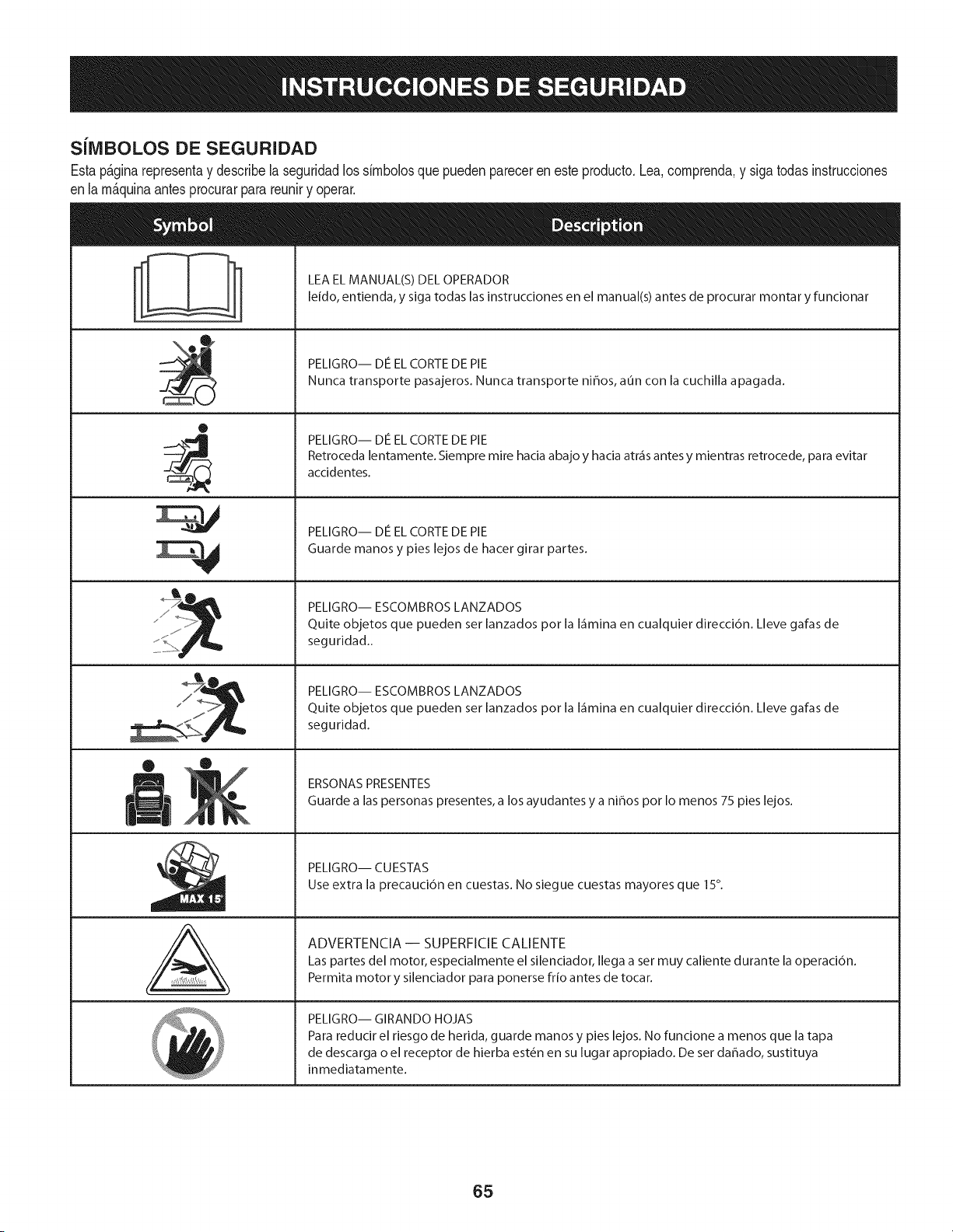
SJlVlBOLOS DE SEGURIDAD
Estap&ginarepresentay describelaseguridadlos simbolosquepuedenpareceren esteproducto.Lea,comprenda,y sigatodasinstrucciones
enla m_quinaantesprocurarpara reuniry operar.
0
AL
LEA EL MANUAL(S) DEL OPERADOR
leido, entienda, y siga todas las instrucciones en el manual(s) antes de procurar montar y funcionar
PELIGRO-- DE EL CORTE DE PIE
Nunca transporte pasajeros. Nunca transporte ni_os, aun con la cuchilla apagada.
PELIGRO-- DE EL CORTE DE PIE
Retroceda lentamente. Siempre mire hacia abajo y hacia atr_is antes y mientras retrocede, para evitar
accidentes.
PELIGRO-- DE EL CORTE DE PIE
Guarde manos y pies lejos de hacer girar partes.
PELIGRO-- ESCOMBROS LANZADOS
Quite objetos que pueden ser lanzados pot la I_imina en cualquier direcci6n. Lleve gafas de
seguridad..
PELIGRO-- ESCOMBROS LANZADOS
Quite objetos que pueden ser lanzados pot la I_imina en cualquier direcci6n. Lleve gafas de
seguridad.
ERSONAS PRESENTES
Guarde alas personas presentes, a los ayudantes y a ni_os pot Io menos 75 pies lejos.
PELIGRO-- CUESTAS
Use extra la precauci6n en cuestas. No siegue cuestas mayores que 15°.
ADVERTENCIA -- SUPERFICIE CALIENTE
Las partes del motor, especialmente el silenciador, Ilega a set muy caliente durante la operaci6n.
Permita motor y silenciador para ponerse frio antes de tocar.
PELIGRO-- GIRANDO HOJAS
Para reducir el riesgo de herida, guarde manos y pies lejos. No funcione a menos que la tapa
de descarga o el receptor de hierba est_n en su lugar apropiado. De ser dahado, sustituya
inmediatamente.
65
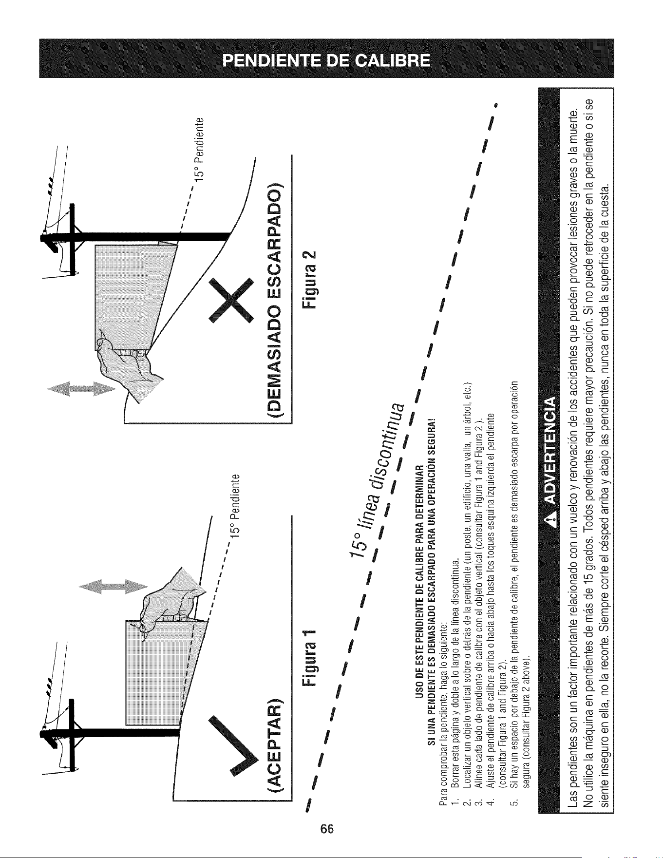
(ACEPTAR)
I5 ° Pendiente
X
(DEMASIADO ESCARPADO)
15° Pendiente
• Figura1
"'"
USO DE ESTE PENDiENTE DE CALIBRE PARA DETERrvIINAR
SlUNA PENDIENTEES DEIVlASIADOESCARPADO PARA UNA OPEBACION SEGURA!
Para comprobar la pendiente, haga Io siguiente:
1. Borrar esta p_ginay doble a Io largo de la linea discontinua.
2.
3.
4.
5,
Localizar un objeto vertical sobre o detr_.sde la pendiente (un poste, un edificio, una valla, un _.rbol,etc.)
Alinee cada lado de pendiente de calibre con el objeto vertical (consultar Figura 1 and Figura 2 ).
Ajuste el pendiente de calibre arriba o hacia abajo hasta los toques esquina izquierda el pendiente
(consultar Figura 1 and Figura 2).
Si hay un espacio por debajo de la pendiente de calibre, el pendiente es demasiado escarpa por operaci6n
segura (consultar Figura 2 above).
Figura 2
Las pendientes son un factor importante relacionado con un vuelco y renovaci6nde los accidentes que pueden provocar lesiones graves o la muerte.
No utilice la ma.quinaen pendientesde ma.sde 15 grados. Todospendientes requiere mayor precauci6n. Si no puede retroceder en la pendienteo si se
siente inseguro en ella, no la recorte. Siemprecorte el cesped arriba y abajo las pendientes, nunca en toda la superficie de la cuesta.
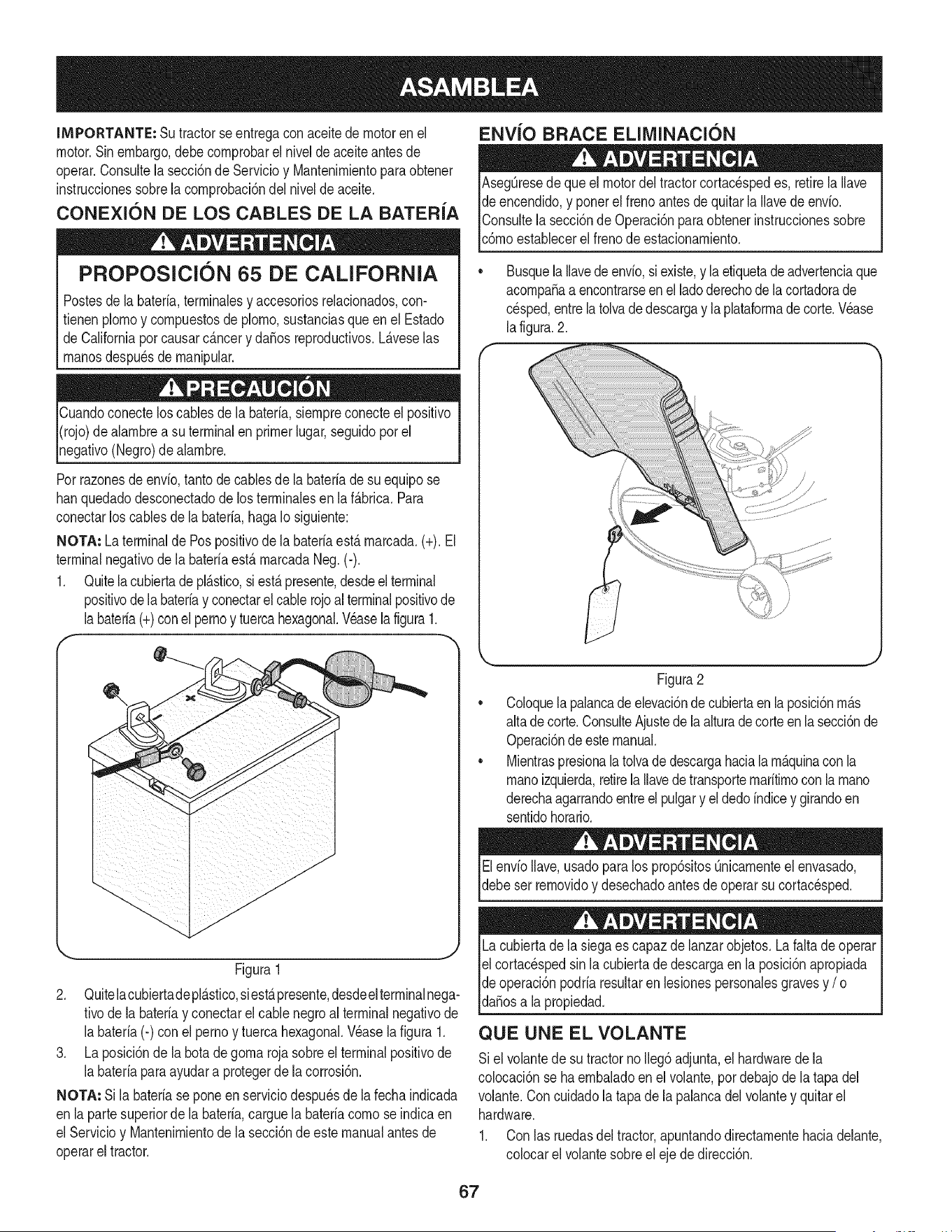
IMPORTANTE: Su tractorseentregaconaceitedemotoren eJ
motor.Sinembargo,debecornprobarel niveldeaceiteantes de
operar.Consultela secci6nde Servicioy Mantenirnientoparaobtener
instruccionessobrelacornprobaci6ndelnivelde aceite.
CONEXION DE LOS CABLES DE LA BATERIA
PROPOSlClON 65 DE CALiFORNiA
Postesdela bateria,terrninalesy accesoriosrelacionados,con-
tienen plornoy cornpuestosde pJorno,sustanciasqueen el Estado
de Californiaporcausarc_.ncery daSosreproductivos.L_.veselas
rnanosdespu_sde rnanipular.
Cuandoconecteloscablesde la bateria,siernpreconecteel positivo
I(rojo)de alarnbrea su terminalenprimerlugar,seguidoporel
pgativo (Negro)de alarnbre.
Porrazonesde envb, tanto de cablesde la bateriade su equipose
hanquedadodesconectadode los terrninalesen la f_.brica.Para
conectarlos cablesde la bateria,hagaIo siguiente:
NOTA: La terminalde Pospositivode labateriaest,.rnarcada.(+). El
terminalnegativode la bateriaestArnarcadaNeg.(-).
1. Quitela cubiertadeplAstico,siestApresente,desdeelterminal
positivode labateriay conectarelcablerojo al terminalpositivode
labateria(+)conel pernoy tuercahexagonal.Veaselafigura1.
f --,,
ENVlO BRACE ELllVIINACION
AsegQresede que el motordel tractorcortacespedes, retirelaIlave
de encendido,y ponerel frenoantesde quitarla Ilavedeenvio.
IConsultela secci6nde Operaci6nparaobtenerinstruccionessobre
lc6rnoestaNecerel frenode estacionarniento.
Busquela Ilavedeenvio,siexiste,y la etiquetadeadvertenciaque
acornpaSaa encontrarseenel ladoderechode lacortadorade
cesped,entrela tolvade descargay laplataforrnadecorte.Wase
la figura.2.
//
Figura1
2. Quitelacubiertadepl_.stico,siest,.presente,desdeelterminalnega-
tivode labateriay conectarel cablenegroal terminalnegativode
la bateria(-) con el pernoy tuercahexagonal.Wase la figura 1.
3. La posici6nde la botadegorna rojasobreel terminalpositivode
la bateriaparaayudara protegerde la corrosi6n.
NOTA: Si la bateriase poneen serviciodespu_sde la fecha indicada
en lapartesuperiorde la bateria,carguela bateriacornose indicaen
el Servicioy Uantenirnientode la secci6ndeeste manualantesde
operarel tractor.
Figura2
CoJoquela palancade elevaci6ndecubiertaen laposici6nrn_.s
altade corte.ConsulteAjustede laalturadecorteenlasecci6nde
Operaci6ndeestemanual.
MientraspresionalatoJvade descargahaciala rn_.quinacon la
rnanoizquierda,retirela Ilavedetransporternaritirnoconla rnano
derechaagarrandoentreel pulgary el dedoindicey girandoen
sentidohorario.
ElenvioIlave,usadoparalos prop6sitosQnicarnenteel envasado,
debeser rernovidoy desechadoantesde operarsu cortacesped.
Lacubiertade la siegaes capaz de lanzarobjetos.La faltade operar
el cortac_spedsin lacubiertade descargaen la posici6napropiada
de operaci6npodriaresultarenlesionespersonalesgravesy / o I
lda_osa a propedad. j
QUE UNE EL VOLANTE
Si el voJantede su tractornoIleg6adjunta,el hardwarede la
colocaci6nse ha ernbaladoenel volante,pordebajode latapa del
volante.Con cuidadola tapade lapalancadelvolantey quitarel
hardware.
1. Con las ruedasdeltractor,apuntandodirectarnentehaciadelante,
colocarel volantesobreel eje de direcci6n.
67
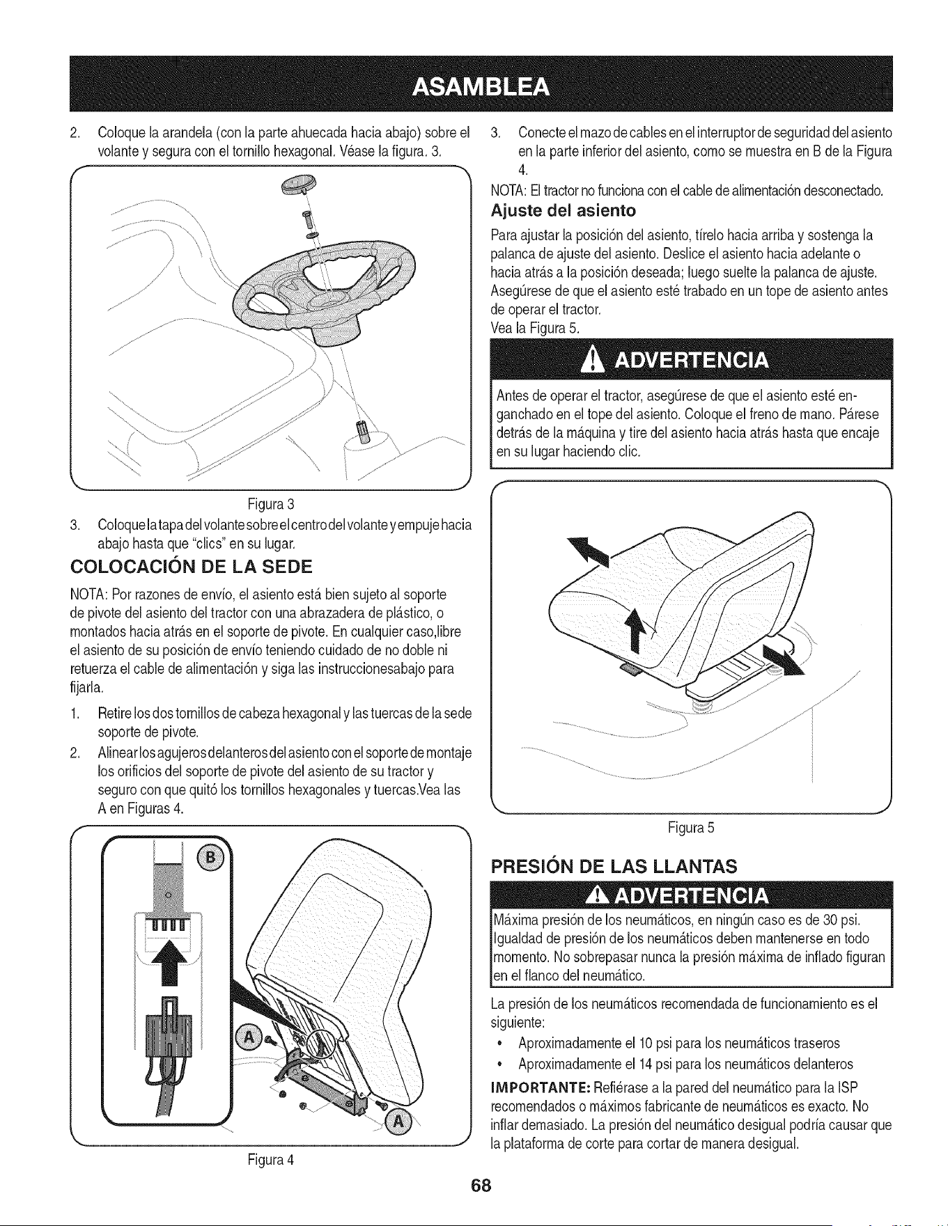
2. Coloquela arandela(con la parteahuecadahaciaabajo) sobreel
volantey seguracon el tornillohexagonal.Wase la figura.3.
f -,
Figura3
3. Coloquelatapadelvolantesobreel centrodelvolanteyempujehacia
abajohastaque "clics"en su lugar.
COLOCAClON DE LA SEDE
NOTA:Porrazonesde envfo,elasientoest,. bien sujetoal soporte
depivotedel asientodel tractorcon unaabrazaderade pl_.stico,o
montadoshaciaatr_.sen elsoportede pivote.Encualquiercaso,libre
el asientode su posici6ndeenvfoteniendocuidadode no doble ni
retuerzael cablede alimentaci6ny sigalas instruccionesabajopara
fijarla.
1. Retirelosdostornillosde cabezahexagonaly lastuercasdelasede
soportede pivote.
2. Alinearlosagujerosdelanterosdelasientoconel soportedernontaje
los orificiosdel soportede pivotedel asientode su tractory
segurocon que quit6los tornilloshexagonalesy tuercas.Vealas
A enFiguras4.
r
Figura4
3. Conecteelmazodecablesenel interruptordeseguridaddelasiento
en la parteinferiordel asiento,como se muestraen Bde la Figura
4.
NOTA:Eltractorno funcionaconel cabledealimentacidndesconectado.
Ajuste del asiento
Paraajustarla posici6ndel asiento,firelohaciaarriba y sostengala
palancadeajustedel asiento.Desliceel asientohaciaadelanteo
haciaatr_.sa la posici6ndeseada;luegosueltela palancade ajuste.
AsegQresede que el asientoest_ trabadoen un topede asientoantes
de operarel tractor.
Veala Figura5.
Antesde operarel tractor,asegQresede queelasientoest_en-
ganchadoenel topedel asiento.Coloqueel frenode mano.P_.rese
detr_.sde la m_.quinay tire del asientohaciaatr_.shastaque encaje
en su lugarhaciendoclic.
Figura5
PFIESl0N DE LAS LLANTAS
M_.ximapresi6nde los neum_.ticos,en ning_ncasoes de 30 psi.
Igualdadde presi6nde los neum_.ticosdebenmantenerseen todo
momento.Nosobrepasarnuncala presi6nm_.ximade infiadofiguran
len e f anco de neum_.tco.
Lapresi6nde los neum_.ticosrecomendadade funcionamientoes el
siguiente:
• Aproximadamenteel 10psi paralos neum_.ticostraseros
• Aproximadamenteel 14psi paralos neum_.ticosdelanteros
INIPORTANTE: Refi_rasea la pareddel neum_.ticoparala ISP
recomendadoso m_.ximosfabricantede neum_.ticoses exacto.No
inflardemasiado.La presi6ndel neum_.ticodesigualpodriacausarque
laplataformade corteparacortarde maneradesigual.
68
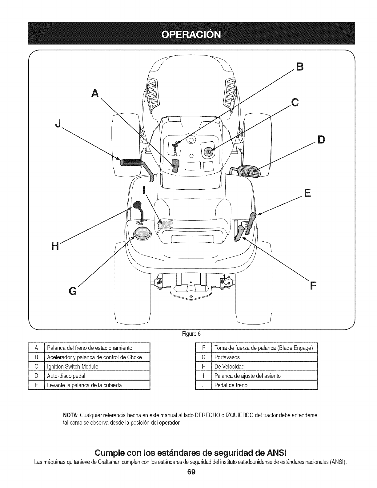
A
J
o
D
E
G
F
A Palancadel frenode estacionamiento
B Aceleradory palancade controlde Choke
C ignitionSwitchModule
D Auto-discopedal
E Levantelapalancadela cubierta
Figure6
F Tomade fuerzade palanca(BladeEngage)
G Portavasos
H DeVelocidad
I Palancade ajustedel asiento
J Pedalde freno
J
NOTA:Cualquierreferenciahechaen este manualal lado DERECHOo IZQUlERDOdeltractordebeentenderse
tal como seobservadesde la posici6ndeloperador.
Curnple con los est_ndares de seguridad de ANSI
Lasm_.quinasquitanievedeCraftsmancumplenconlosest_.ndaresdeseguridaddelinstitutoestadounidensede est_.ndaresnacionales(ANSI).
69
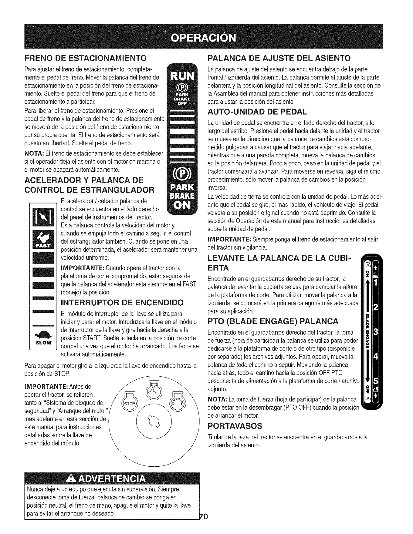
FRENO DE ESTACIONAIVllENTO
Paraajustarel frenode estacionarniento:completa-
rnenteel pedalde freno.Moverla palancadelfrenode
estacionarnientoen la posici6ndel frenodeestaciona-
rniento.Suelteel pedal del frenoparaque el frenode
estacionarnientoa participar.
Paraliberarel frenode estacionarniento:Presioneel
pedalde frenoy la palancadel frenode estacionarniento
se rnover_,de la posici6ndel frenode estacionarniento
porsu propiacuenta.Elfrenode estacionarnientoser_.
puestoenlibertad.Suelteel pedaldefreno.
NOTA: El frenode estacionarnientosedebeestablecer
si el operadordejael asientoconel motoren rnarchao
el motorse apagarAautomAticarnente.
ACELERADOR Y PALANCA DE
CONTROL DE ESTRANGULADOR
/
m
M
m
SLOW
Elacelerador/ cebadorpalancade
controlse encuentraenel ladoderecho
delpanelde instrurnentosdeltractor.
Estapalancacontrolala velocidaddel motory,
cuandoseernpujatodoel caminoa seguir,el control
delestranguladortarnbi_n.Cuandoseponeen una
posici6ndeterrninada,el aceleradorser_.rnanteneruna
velocidaduniforrne.
IMPORTANTE: Cuandoopereel tractorcon la
plataforrnade cortecornprornetido,estar segurosde
quela palancadel aceleradorest,. siernpreen el FAST
(conejo)la posici6n.
INTERRUPTOR DE ENCENDIDO
El rn6dulodeinterruptorde la Ilavese utilizapara
iniciary pararel motor.Introduzcala Ilaveenel rn6dulo
de interruptorde la Ilavey gire hacialaderechaa la
posici6nSTART.Sueltelateda en la posici6ndecorte
normalunavez que el motorha arrancado.Losfaros se
activarAautornAticarnente.
Paraapagarel motorgirea la izquierdala Ilavede encendidohastala
posici6ndeSTOR
IMPORTANTE: Antesde
operarel tractor,se refieren
tantoal "Sisternade bloqueode
seguridad"y "Arranquedel motor"
rn_.sadelanteen esta secci6nde
estemanualpara instrucciones
detalladassobrela Ilavede
encendidodel rn6dulo.
PALANCA DE AJUSTE DEL ASIENTO
Lapalancade ajustedel asientose encuentradebajode la parte
frontal/izquierda delasiento.Lapalancaperrniteel ajuste de la parte
delanteray laposici6nlongitudinaldel asiento.Consultelasecci6nde
la Asarnbleadel manualparaobtenerinstruccionesrn_.sdetalladas
paraajustarla posici6ndel asiento.
AUTO-UNIDAD DE PEDAL
Launidadde pedalse encuentraenel lado derechodel tractor,a Io
largodel estribo.Presioneel pedalhaciadelantela unidady el tractor
se rnueveen la direcci6nque la palancade carnbiosest,.cornpro-
rnetidopulgadasa causarque el tractorparaviajar haciaadelante,
rnientrasquea una paradacornpleta,rnuevala palancade carnbios
en la posici6ndelantera.Pocoa poco, pasoenla unidadde pedaly el
tractorcornenzar_,a avanzar.Pararnoverseen reversa,sigael rnisrno
procedirniento,s61omoverla palancade carnbiosenla posici6n
inversa.
Lavelocidadde tierra se controlacon la unidadde pedal.Lorn_.sadel-
anteque el pedal se gir6,el rn_.sr_.pido,el vehiculode viaje. El pedal
volver_,a su posici6noriginalcuandonoest,. deprirnido.Consultela
secci6nde Operaci6nde este manualparainstruccionesdetalladas
sobrela unidadde pedal.
IMPORTANTE: Siernprepongael frenode estacionarnientoal salir
del tractorsinvigilancia.
LEVANTE LA PALANCA DE LA CUBI-
ERTA
Encontradoenel guardabarrosderechodesu tractor,la
palancade levantarla cubiertase usa para carnbiarla altura
de la plataforrnadecorte. Parautilizar,moverla palancaa la
izquierda,secolocar_,en la prirneracategoriarn_.sadecuada
parasu aplicaci6n.
PTO (BLADE ENGAGE) PALANCA
Encontradoenel guardabarrosderechodeltractor,latorna
de fuerza(hojade participar)la palancase utilizaparapoder
dedicarsea laplataforrnade corteo deotrotipo (disponible
por separado)los archivosadjuntos.Paraoperar,rnuevala
palancade todoel carninoa seguir.Moviendola palanca
haciaatr_.s,todo el carninohacia laposici6nOFFPTO
desconectade alirnentaci6na laplataforrnade corte/ archivo
adjunto.
NOTA: La tornade fuerza (hojade participar)de lapalanca
debeestar en la desernbragar(PTOOFF)cuandola posici6n
de arrancarel motor.
PORTAVASOS
Titularde la tazadel tractorse encuentraenel guardabarrosa la
izquierdadelasiento.
Nuncadejea un equipoque ejecutasin supervisi6n.Siernpre |
desconectetornadefuerza,palancade carnbiose pongaen
L
posici6nneutral,el frenode rnano,apagueel motory quitela Ilave
paraevitarel arranqueno deseado. 0
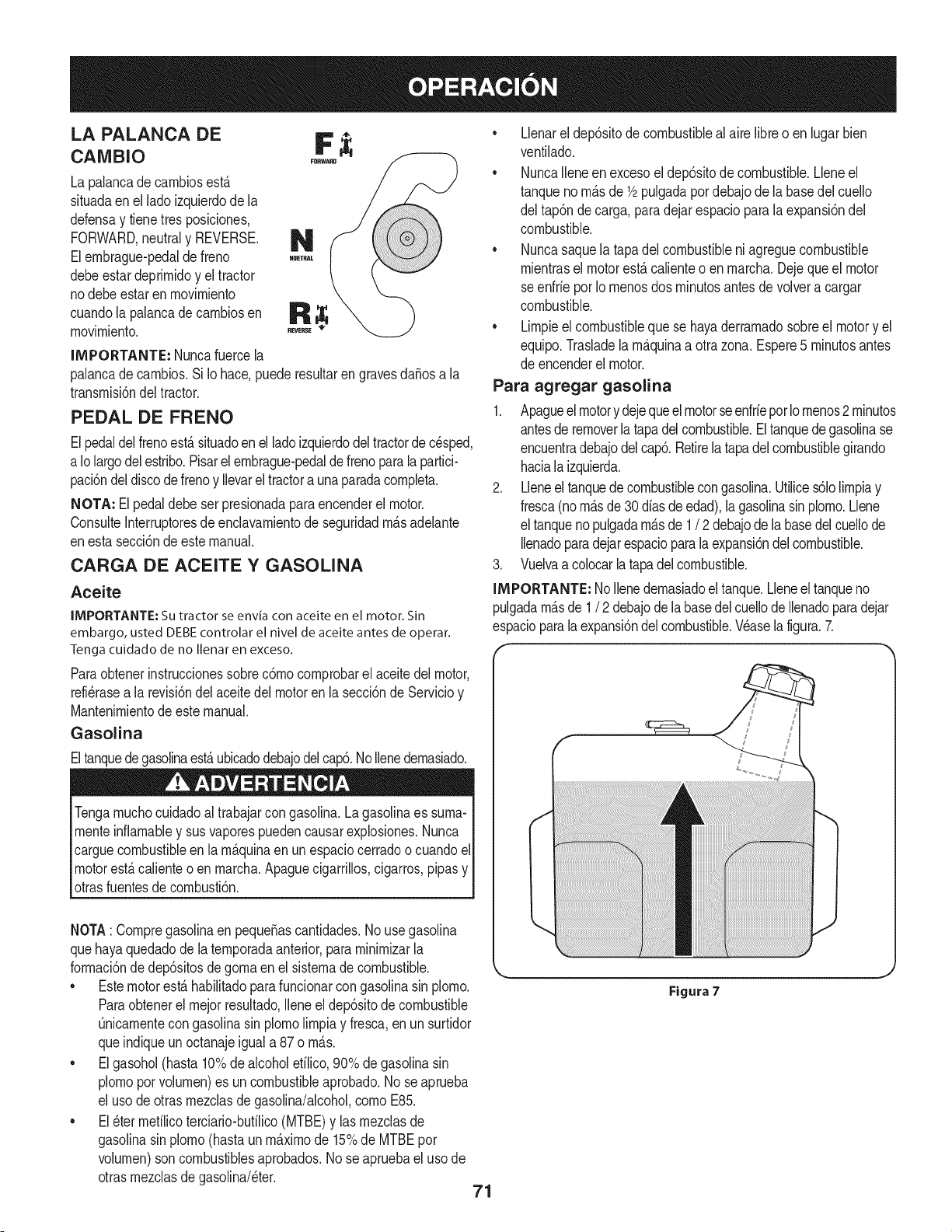
LA PALANCA DE F
CAMBIO
La palancade carnbiosest,.
situadaenel lado izquierdode la
defensay tienetresposiciones,
FORWARD,neutraly REVERSE. _1_
Elernbrague-pedalde freno
debeestardeprirnidoy el tractor
nodebe estar en rnovirniento
cuandola palancade carnbiosen R
rnovirniento.
,T,,E,_
IMPORTANTE: Nuncafuercela
palancade carnbios.Si Io hace,puede resultarengravesdaSosa la
transrnisi6ndel tractor.
PEDAL DE FRENO
Elpedaldelfrenoest,. situadoenel ladoizquierdodel tractorde cesped,
a Iolargodel estribo.Pisarel ernbrague-pedalde frenoparala partici-
paci6ndeldiscode frenoy Ilevarel tractora unaparadacornpleta.
NOTA: El pedal debe ser presionadaparaencenderel motor.
ConsulteInterruptoresde enclavarnientode seguridadrn_.sadelante
enesta secci6ndeeste manual.
CARGA DE ACEITE Y GASOLINA
Aceite
IMPORTANTE: Su tractor se envia con aceite en el motor. Sin
embargo, usted DEBE controlar el nivel de aceite antes de operar.
Tenga cuidado de no Ilenar en exceso.
Paraobtenerinstruccionessobrec6rnocornprobarel aceite del motor,
refi6rasea la revisi6ndel aceitedel motorenla secci6nde Servicioy
Mantenirnientode estemanual.
Gasolina
Eltanquedegasolinaest,.ubicadodebajodelcap6.NoIlenedernasiado.
Tengarnuchocuidadoal trabajarcon gasolina.La gasolinaes surna-
rnenteinfiarnabley susvaporespuedencausarexplosiones.Nunca
carguecombustibleenla rn_.quinaen un espaciocerradoo cuandoel
motorest,.calienteo en rnarcha.Apaguecigarrillos,cigarros,pipasy
otrasfuentesde cornbusti6n.
NOTA: Cornpregasolinaen pequefiascantidades.No usegasolina
quehayaquedadode la ternporadaanterior,pararninirnizarla
forrnaci6nde dep6sitosde gornaen el sisternadecombustible.
• Estemotorest,.habilitadoparafuncionarcongasolinasin plorno.
Paraobtenerel rnejorresultado,Ileneel dep6sitode combustible
Onicarnentecongasolinasin plornolirnpiay fresca,enun surtidor
queindiqueun octanajeigual a 87 o rn_.s.
• Elgasohol(hasta 10%de alcoholefilico,90% de gasolinasin
plornoporvolurnen)es un combustibleaprobado.No seaprueba
el usode otrasrnezclasde gasolina/alcohol,cornoE85.
• El6ter rnefilicoterciario-bufilico(MTBE)y las rnezclasde
gasolinasin plorno(hastaun rn_.xirnode 15%de MTBEpor
volurnen)son combustiblesaprobados.Nose apruebael uso de
otrasrnezclasdegasolina/eter.
• Llenarel dep6sitode combustiblealaire libreo en lugarbien
ventilado.
• NuncaIleneen excesoel dep6sitode combustible.Lleneel
tanqueno rn_.sde 1/2pulgadapordebajode la basedel cuello
del tap6nde carga, paradejar espacioparalaexpansi6ndel
combustible.
• Nuncasaquela tapadel combustibleni agreguecombustible
rnientrasel motorest,. calienteo en rnarcha.Dejequeel motor
seenfrie porIornenosdos rninutosantesde volvera cargar
combustible.
• Lirnpieel combustiblequese hayaderrarnadosobreel motory el
equipo.Trasladelarn_.quinaa otrazona. Espere5 rninutosantes
de encenderelmotor.
Para agregar gasolina
1. Apagueelmotory dejequeel motorseenfriepot Iornenos2 rninutos
antesde removerlatapadel combustible.Eltanquedegasolinase
encuentradebajodelcap6.Retirela tapadelcombustiblegirando
hacialaizquierda.
2. Lleneel tanquede combustiblecongasolina.Utilices61olirnpiay
fresca(norn_.sde30diasde edad),lagasolinasinplorno.Llene
el tanquenopulgadarn_.sde 1/ 2 debajode labasedelcuellode
Ilenadoparadejarespacioparalaexpansi6ndelcombustible.
3. Vuelvaacolocarla tapadelcombustible.
IMPORTANTE: NoIlenedernasiadoeltanque.Lleneel tanqueno
pulgadarn_.sde 1/ 2 debajodela basedel cuellode Ilenadoparadejar
espacioparalaexpansi6ndelcombustible.V6aselafigura.7.
71
Figura 7
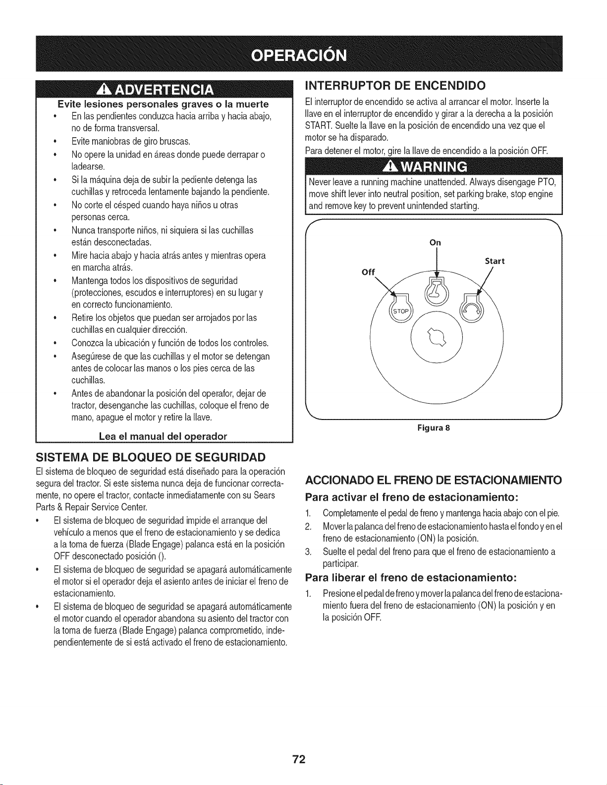
Evite lesiones personales graves o la muerte
• Enlaspendientesconduzcahaciaarribay haciaabajo,
node forrnatransversal.
• Eviternaniobrasde girobruscas.
• No operela unidaden _.reasdondepuedederraparo
ladearse.
• Si larn_.quinadejade subirla pedientedetengalas
cuchillasy retrocedalentarnentebajandola pendiente.
• No corteel c_spedcuandohayani_osu otras
personascerca.
• Nuncatransporteni_os,ni siquierasi las cuchillas
est_.ndesconectadas.
• Mirehaciaabajoy haciaatr_.santesy rnientrasopera
en rnarchaatr_.s.
• Mantengatodoslos dispositivosde seguridad
(protecciones,escudose interruptores)ensu lugary
encorrectofuncionarniento.
• Retirelos objetosquepuedanserarrojadosporlas
cuchillasencualquierdirecci6n.
• Conozcalaubicaci6ny funci6nde todoslos controles.
• AsegQresedeque las cuchillasy el motor sedetengan
antesde colocarlas rnanoso los piescercade las
cuchillas.
• Antesde abandonarlaposici6ndel operafor,dejarde
tractor,desenganchelascuchillas,coloqueel frenode
rnano,apagueel motory retirela Ilave.
Lea el manual del o erador
INTERRUPTOR DE ENCENDIDO
Elinterruptorde encendidose activaal arrancarel motor.Insertela
Ilaveen el interruptorde encendidoy girara la derechaa la posici6n
START.Sueltela Ilaveen la posici6nde encendidouna vez que el
motorse ha disparado.
Paradetenerel motor,girela Ilavede encendidoa la posici6nOFR
Neverleavea runningmachineunattended.AlwaysdisengagePTO,
moveshiftleverinto neutralposition,set parkingbrake,stopengine
and removekeyto preventunintendedstarting.
F
On
Start
off
Figura 8
SISTENIA DE BLOQUEO DE SEGURIDAD
El sisternade bloqueode seguridadest,. diseSadoparala operaci6n
seguradel tractor.Si este sisternanuncadeja de funcionarcorrecta-
rnente,noopere el tractor,contacteinrnediatarnentecon su Sears
Parts& RepairServiceCenter.
• El sisternade bloqueode seguridadirnpideel arranquedel
vehiculoa rnenosque elfrenode estacionarnientoy se dedica
a latornade fuerza (Blade Engage)palancaest,.en la posici6n
OFFdesconectadoposici6nO.
• El sisternade bloqueode seguridadseapagar_,autorn_.ticarnente
el motorsi el operadordejael asientoantesde iniciarel frenode
estacionarniento.
• El sisternade bloqueode seguridadseapagar_,autorn_.ticarnente
el motorcuandoel operadorabandonasuasientodel tractorcon
latornade fuerza(Blade Engage)palancacornprornetido,inde-
pendienternentede si est,.activadoel frenode estacionarniento.
ACCIONADO EL FRENO DE ESTACIONAMIENTO
Para activar el freno de estacionamiento:
1. Cornpletarnenteelpedaldefrenoy rnantengahaciaabajoconel pie.
2. Moverlapalancadelfrenode estacionarnientohastaelrondoyen el
frenode estacionarniento(ON)la posici6n.
3. Suelteel pedaldel frenoparaqueel frenodeestacionarnientoa
participar.
Para liberar el freno de estacionamiento:
1. Presioneelpedaldefrenoyrnoverlapalancadelfrenodeestaciona-
rnientofueradel frenodeestacionarniento(ON) la posici6nyen
la posici6nOFE
72
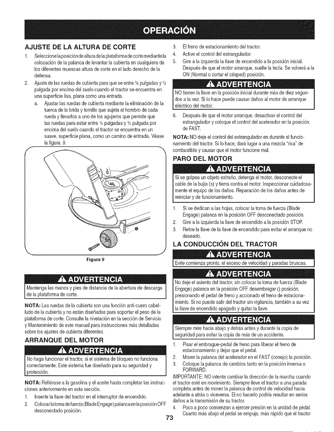
AJUSTE DE LA ALTURA DE CORTE
.
F
Seleccionelaposici6ndealturadelaplataforrnadecorternediantela
colocaci6nde la palancade levantarla cubiertaencualquierade
los diferentesrnuescasalturade corte en el lado derechode la
defensa.
Ajustedelas ruedasde cubiertaparaqueseentre1Apulgadasy 1/2
pulgadapot encirnadel suelocuandoeltractorse encuentraen
unasuperficielisa, planacornounaentrada.
a. Ajustarlas ruedasde cubiertarnediantela elirninaci6nde la
tuercade labrida y tornilloquesujetael hornbrode cada
rueday Ilevarlosa unode losagujerosque perrniteque
las ruedaspara estar entre1Apulgadasy 1/2pulgadapor
encirnadelsuelocuandoel tractorse encuentraen un
suave,superficieplana,cornouncarninode entrada.Wase
la figura.9.
'_., j
Figura 9
Mantengalas rnanosy piesde distanciade la aberturade descarga
de la plataforrnadecorte.
NOTA: Las ruedasde lacubiertasonuna funci6nanti-cuerocabel-
ludode la cubiertay no est_.ndiseSadosparasoportarel pesode la
plataforrnadecorte. Consultelanivelaci6nen lasecci6nde Servicio
y Mantenirnientodeeste manualpara instruccionesrn_.sdetalladas
sobrelos ajustesdecubiertadiferentes.
ARRANQUE DEL MOTOR
No hagafuncionarel tractor,si el sisternade bloqueonofunciona
correctarnente.EstesisternaruediseSadopara su seguridady
protecci6n.
NOTA: Refi_rasea la gasolinay el aceitehastacornpletarlas instruc-
clonesanteriorrnenteen esta secci6n.
1. Insertela Ilavedel tractoren el interruptordeencendido.
2. Colocarlatornadefuerza(BladeEngage)palancaenlaposici6nOFF
desconectadoposici6n.
3. Elfrenodeestacionarnientodeltractor.
4. Activeel controldel estrangulador.
5. Girea la izquierdala Ilavede encendidoa la posici6ninicial.
Despu_sde queel motorarranque,sueltelatecla. Se volver_,a la
ON(Normalo cortarel c_sped)posici6n.
NOtienenla Ilaveen la posici6ninicialdurantern_.sde diezsegun-
dos a la vez. SiIo hacepuedecausardaSosal motorde arranque
el_ctricodel motor.
6. Despu_sde que el motorarranque,desactivarel controldel
estranguladory coloqueel controldel aceleradoren la posici6n
de FAST.
NOTA: NOdejeel controldel estranguladorenduranteel funcio-
narnientodel tractor.SiIo hace,dar_.lugar a una rnezcla"rica"de
combustibley causarqueel motorfuncionernal.
PARO DEL MOTOR
Si se golpeaun objetoextraSo,detengael motor,desconecteel
cablede la bujfa(s) y tierracontrael motor.Inspeccionarcuidadosa-
rnenteel equipode losdaSos.Reparaci6nde los daSosantes de
reiniciary defuncionarniento.
1. Sise dedicanalas hojas,colocarla tornadefuerza (Blade
Engage)palancaen la posici6nOFFdesconectadoposici6n.
2. Girea la izquierdala Ilavede encendidoa la posici6nSTOR
3. RetirelaIlavede la Ilavede encendidoparaevitarelarranqueno
deseado.
LA CONDUCCION DEL TRACTOR
Evitecornienzapronto,el excesode velocidady paradasbruscas.
Nodeje el asientodel tractor,sincolocar la tornadefuerza (Blade
Engage)palancaen la posici6nOFF desernbragar0 posici6n,
presionandoel pedalde frenoy accionadoel frenode estaciona-
rniento.Si no puedesalirdeltractorsin vigilancia,tarnbi_na suvez
la Ilavedeencendidoapagadoy quitarla Ilave.
Siernpremirehaciaabajoy detr_.santesy durantela copiade
seguridadparaevitarla copiade rn_.sde un accidente.
1. Pisarel ernbrague-pedalde freno paraliberarel frenode
estacionarnientoy dejarqueel pedal.
2. Moverlapalancadel aceleradoren el FAST(conejo)la posici6n.
3. Coloquelapalancadecarnbiostantoenla posici6ninversao
FORWARD.
IMPORTANTE:NOintentecarnbiarla direcci6nde la rnarchacuando
el tractorest_en rnovirniento.SiernpreIleveel tractora una parada
cornpletaantesde moverla palancadecontroldevelocidadhacia
adelantea atr_.soviceversa.Elno hacerlopodriaresultarenserios
da_osa la transrnisi6nde su tractor.
4. Pocoa poco cornienzana ejercerpresi6nen la unidadde pedal.
Cuantorn_.sabajoel pedal seernpuja,rn_.sr_.pidoqueeltractor
73

se desplazar_,en la direcci6ndeseadasobrelabasede la
posici6ndela palancade carnbios.
5. Eltractordecespedes Ilevadoa unaparadaporla liberaci6nde
la unidaddepedal y luegooprirnirel pedalde freno.
AI pararel tractor,porcuaiquierrnotivo,rnientrasqueen unasuperficie
de hierba,siernpre:
1. Coloquela palancadecarnbiosen puntornuerto,
2. Apliqueelfreno deestacionarniento,
3. Apagueel motory quitarla Ilave.Si Iohace, reducir_,al rninirnola
posibilidadde quesu c_spedse dore""porelescapecalientedel
motorde sutractor.
Antesdeabandonarla posici6ndeloperadorporcualquierraz6n,
separarlas hojas,poner la palancade controlde velocidaden
I neutral,pongael freno deestacionarniento,paradamotorapagadoy
_quitarla Ilave.
CONDUCCION EN LAS LADERAS
Refierenal anchodeia pendienteen ia seguridadde las pr_.cticasde
operaci6nirnportantesecci6ndelmanualparaayudara deterrninar
zonasde laderadondepuedeoperarel tractorcon total seguridad.
No corteel cespeden pendientescon una inclinaci6nde rn_.sde 15
grados(un aurnentodeaproxirnadarnente2-1/2pies cada 10pies).
Eltractorpuedevolcary causarlesionesgraves.
INVOLUCRAR A LOS BLADES
Participaci6ndela tornadefuerza(BladeEngage)lastransferenciasde
energiaa la plataforrnadecorteo deottotipo(disponibiepot separado)
los archivosadjuntos.Paraparticipardelas hojas,haga Iosiguiente:
1. Moverla palancade controldel aceleradora la r_.pida(conejo)la
posici6n.
2. Sujetela tornade fuerza(Blade Engage)y girar la palancade
todo el carninoa seguira los novios(ON)la posici6n.
3. Mantengala palancadel aceleradoren el FAST(conejo)la
posici6nparaei usorn_.seficientede la plataforrnade corteo de
otto tipo (disponiblepor separado)los archivosadjuntos.
NOTA: Ei motorse apagar_,autorn_.ticarnentesi latornadefuerza
est,.cornprornetidocon ia palancadecarnbiosen la posici6nde
rnarchaatr_.scon iailavede encendidoen la posici6nON.
USO DE LA CUBIERTA DE LEVANTE LA
PALANCA DE
Paraeievarla plataforrnade corte,moverla palancade elevaci6nde
cubiertaa la izquierda,iuegosecoiocaenla ranurarn_.sadecuada
parasu aplicaci6n.ConsulteAjuste laaiturade corte anteriorrnenteen
estasecci6n.
• Corteel cespedy las pendientes,nuncatransversal.
• Tengaextrernaprecauci6nai carnbiarde direcci6nen las
pendientes.
• Watchparalos agujeros,grietas,baches,piedrasu otrosobjetos
ocultos.Terrenoirregularpuederevertirla rn_.quina.El c_sped
alto puedeocultarobst_.culos.
• Evitegirarcuandosecirculapor una pendiente.Siunavez,debe
hacerse,a suvez por la pendiente.Elregresodeuna pendiente
aurnentala posibilidadde un rollover.
• Evitedetenersecuandose conducepot una pendiente.Si es
necesariodetenerrnientrasse conducepot una pendiente,
puestaen rnarchasin problernasy con cuidadopara reducirla
posibilidadde volteareltractorhaciaatr_.s.
74
CORTAR
Paraayudara evJtarel contactocon lacuchJllao una lesJ6nen
elobjetolanzado,Mantengaa losespectadores,losayudantes,
los niSosy las mascotasporIo menos75piesde distanciade la
m_.quinamientrasest,.en funcionamiento.Paradade la m_.quina,si
alguienentraen el _.rea.
La sJguJenteinformacJ6nser_.Qtilcuandose utilizala plataformade
cortecon sutractor:
Plande su patr6nde corte para evitarla descargade materiales
hacialas carreteras,aceras,transeQntes,etc.Adem_.s,evitematerial
quese descargacontrauna paredo una obstrucci6nquepuede
causaraltamateriala rebotarhaciael operador.
FAROS
• LasI_.mparasest_.nONcuandoel motordeltractorse est,.
ejecutando.
• Laslucesse apagacuandola Ilavede contactose muevea la
posici6nSTOE
• No corteel c6speda la velocidaddeterrenoelevado,especial-
mentesi se ha instaladoun kit de mantilloo colectorde cesped.
• Paraobtenerlos mejoresresultadosse recomiendaquelas
dos primerasvueltassecortar&con la aprobad6nde la gesti6n
arrojadohaciael centro.Traslasdos primerasvueltas,invertirel
sentidodelanzarla descargahaciael exteriorde labalanzade
corte.Esto le dar&una mejoraparienciaal c6sped.
• No corteel cespeddemasiadocorto.Pastocortoinvitacreci-
mientode malashierbasy losamarilloscon rapidezenel tiempo
seco.
Cortarel c6spedsiemprese debe hacercon el motora todogas.
• Bajolascondicionesm_.spesadas,puedesernecesariovolversobre
lazonadelcorteporsegundavezparaobteneruncortelimpio.
• NOintentecortarespesamalezay malashJerbasyelpastomuyalto.
Sutractorest&diseSadoparacortarelc6sped,uncepillonoest&claro.
Mantengalascuchillasafiladasy sustituirlascuchillasencaso
dedesgaste.ConsulteHojasde corte en el servicioy la secci6n
Mantenimientode este manualde instruccionesde afilarla hoja
adecuada.
75

LISTA DE iVlANTENIIVllENTO
Antesde realizarcualquiertipodel rnantenirniento/servicio,suelte
todoslos rnandosy pareel motor.Esperehasta que todaslas partes
dernovirnientohayanvenidoa una paradacornpleta.Desconecteel
alarnbrede bujiay b_.selocontraelmotorparaprevenirel cornienzo
involuntario.SiernpreIlevepuestoscristalesinastillablesdurantela
operaci6no realizandocualquierajusteo reparaciones.
Sigala lista de rnantenirnientodadaabajo.Estacartadescribepautas
de servicios61o.Usela colurnnade Troncode Servicioparaguardarla
pistade tareasde rnantenirnientocornpletadas.
Localizarel rn_scereanoCharnuscael Centrode Servicio o pro-
grarnar el servicio,sirnplementeponerseen eontactoChamusca
en 1-800-4-MY-HOME®.
Antesde cadauso
Losprirneroscinco horas
Cada10 horas
Cada 25 horas
Cada50 horas
Anualrnente
Antesde Alrnacenaje
1. Niveldelaceite de motor
2. Silenciadorzonay los controles
3. Dedode la rnanode guardia
1. Elaceitedel motor
1. EIcap6/Ios respiraderos
2. Losbornesdela bateria
3. Loshusillosy la rn_nsulainterrnediade la
plataforrna
1. El depuradordelfiltro de aire*
2. Filtrode aire*
3. Losbrazosde rnandointerrnedios,ejes del
pivotey ejes
4. Losrodarnientosdelas ruedasdelanteras
5. Las ruedasdelanterasdela plataforrna
1. El aceitedel motor/el filtrodeaceite
2. Silenciador
1. Filtrodeaire
2. Eldepuradordelfiltrode aire
3. Bujia
4. Sisternade refrigeraci6nporaire *
5. Filtrode combustible
6. DirectivoEngranajes
7. Ruedastraseras
1. EIcap6/Ios respiraderos
2. Losbornesdela bateria
3. Losbrazosde rnandointerrnedios,ejes del
pivotey ejes
4. Losrodarnientosdelas ruedasdelanteras
5. Las ruedasdelanterasdela plataforrna
6. Loshusillosy la rn_nsulainterrnediade la
plataforrna
7. Lospuntosde pivotedelpedal
* Realiceel serviciorn_.sfrecuenternentecuandohayarnuchopolvo.
Antesde realizartareasdernantenirnientoo reparaciones,desco-
nectela potenciade arranque(PTO),coloqueel frenode rnano,
apagueel motory retirela Ilave,paraevitar el encendidoaccidental
del motor.
1. Cornprobar
2. Lirnpie
3. Lirnpie
1. Carnbie
1. Lirnpie
2. Lirnpie
3. Lubrique
1. Lirnpie
2. Lirnpie
3. Lubrique
4. Lubrique
5. Lubrique
1. Carnbie/reernplace
2. Cornprobar
1. Reernplace
2. Reernplace
3. Reernplace
4. Lirnpie
5. Reernplace
6. Lirnpie
7. Quitelagrasay losejes
1. Lirnpie
2. Lirnpie
3. Lubrique
4. Lubrique
5. Lubrique
6. Lubrique
Z Lubrique
Siel motorse ha puestoen funcionarnientorecienternente,el motor,
silenciadory las superficiesrnet_.licascircundantesestar_.ncalientes
Iy puedencausarquernadurasa la piel.Tengaprecauci6nparaevitar
lquernaduras.
76
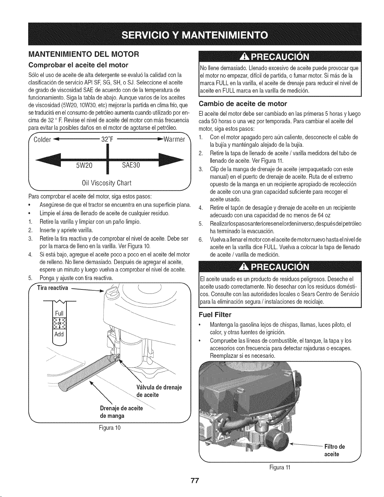
iVlANTENIIVllENTODEL MOTOR
Comprobar el aceite del motor
$61oeluso deaceite de alta detergenteseevalu6la calidadcon la
clasificaci6nde servicioAPI SF,SG,SH,o SJ.Seleccioneel aceite
degrado de viscosidadSAEdeacuerdoconde laternperaturade
funcionarniento.Sigala tablade abajo.Aunquevariosde los aceites
deviscosidad(5W20,10W30,etc) rnejorarla partidaenclirnafrio,que
setraducir&enel consurnodepetr61eoaurnentacuandoutilizadopot en-
cirnade 32 o R Reviseel nivelde aceite del motorcon rn&sfrecuencia
paraevitarla posiblesdaSosen el motorde agotarseel petr61eo.
Colder _ 32°F =,"-Warmer
Oil Viscosity Chart
J
Paracornprobarel aceitedel motor,sigaestospasos:
• AsegOresede queel tractorseencuentraen unasuperficieplana.
Lirnpieel&teade Ilenadode aceitedecualquierresiduo.
1. Retirela varillay lirnpiarcon un pasolirnpio.
2. Insertey aprietevarilla.
3. Retirela tira reactivay decornprobarel nivelde aceite.Debeser
porla rnarcade Ilenoen lavarilla.Vet Figura10.
4. Siest&bajo,agregueelaceite pocoa pocoen elaceitedelmotor
de relleno.No Ilenedernasiado.Despu_sde agregarel aceite,
espereun rninutoy luego vuelvaa cornprobarel nivelde aceite.
5. Pongay ajustecon tira reactiva.
fTi,o,oootivo
Wlvula de drenaje
de aceite
Drenajede aceite
No Ilenedernasiado.Llenadoexcesivodeaceite puedeprovocarque
el motornoernpezar,diffcilde partida,o furnarmotor.Si rn&sde la
rnarcaFULLen lavarilla,el aceitede drenajeparareducirel nivelde
aceiteen FULLrnarcaen la varilladernedici6n.
Cambio de aceite de motor
Elaceitedel motordebeset carnbiadoen las prirneras5 horasy luego
cada50 horaso unavez por ternporada.Paracarnbiarel aceitedel
motor,sigaestospasos:
1. Conel motorapagadoperoaOncaliente,desconecteel cablede
labujia y rnant_ngaloalejadode la buj[a.
2. Retirelatapade Ilenadode aceite/ varillarnedidoradeltubo de
Ilenadode aceite.Vet Figura11.
3. Clipdela rnangade drenajedeaceite (ernpaquetadocon este
manual)en el puertode drenajede aceite.Rutade el extrerno
opuestode larnangaen un recipienteapropiadode recolecci6n
de aceitecon una grancapacidadsuficientepararecogerel
aceiteusado.
4. Retireeltap6nde desag(Jey drenajedeaceite en un recipiente
adecuadocon una capacidaddeno rnenosde64 oz
5. Realizarlospasosanterioresenelordeninverso,despu_sdelpetr61eo
haterrninadolaevacuaci6n.
6. VuelvaaIlenarelrnotorconelaceitedemotornuevohastaelnivelde
aceiteen la varilladice FULL.Vuelvaa colocarla tapa de Ilenado
de aceite/ varillade rnedici6n.
Elaceiteusadoes un productode residuospeligrosos.Desecheel
aceiteusadocorrectarnente.1/odesecharcon los residuosdorn_sti-
cos. Consultecon lasautoridadeslocaleso SearsCentrodeServicio
_arala elirninaci6nsegura/ instalacionesde reciclaje.
Fuel Filter
Mantengala gasolinalejosde chispas,llamas,lucespiloto,el
calor,y otrasfuentesde ignici6n.
Cornpruebelas lineasdecombustible,el tanque,latapa y los
accesorioscon frecuenciaparadetectarrajaduraso escapes.
Reernplazarsi es necesario.
Figura10
77
Figura11
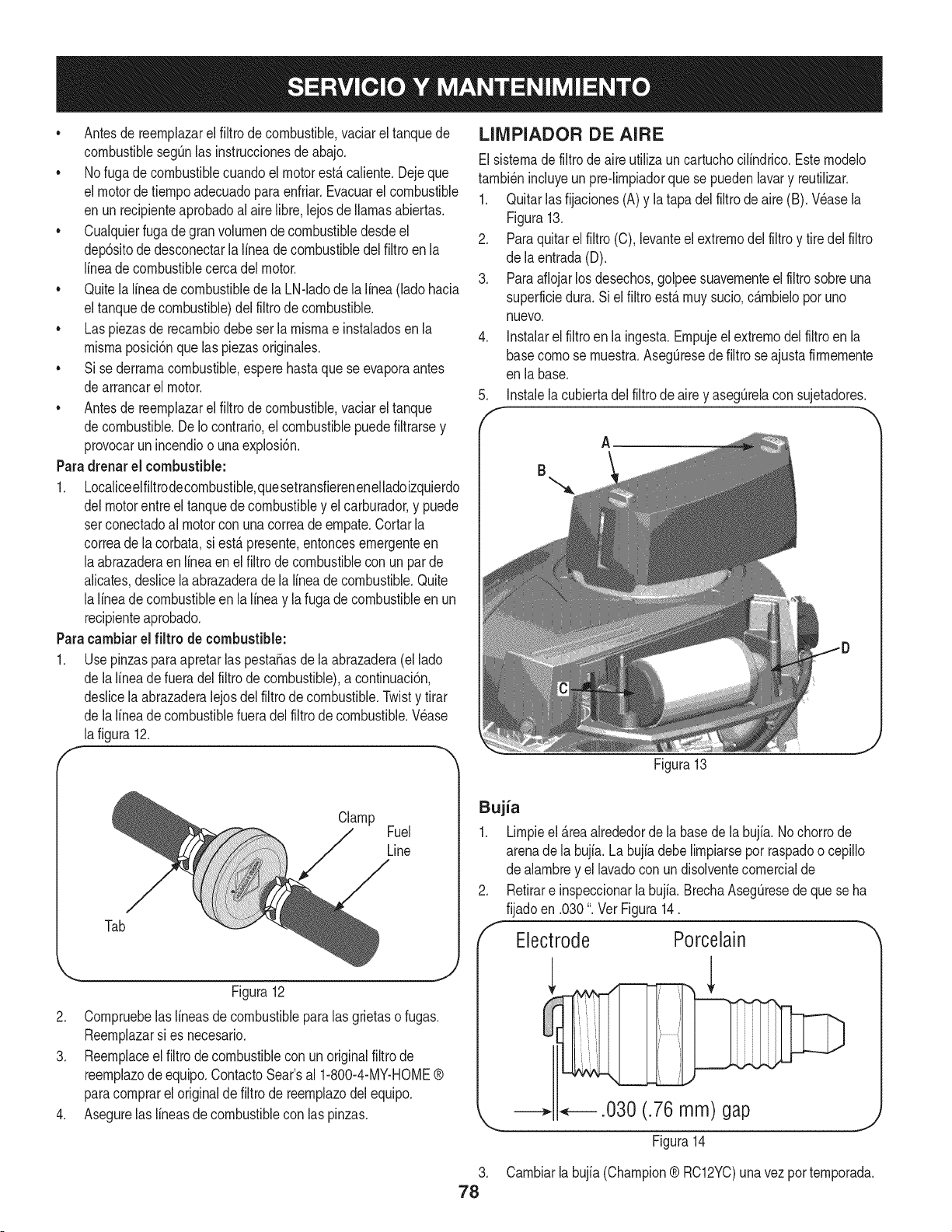
• Antesdereernplazarelfiltrodecombustible,vaciareltanquede
combustiblesegQnlasinstruccionesdeabajo.
• Nofugadecombustiblecuandoelmotorest,.caliente.Dejeque
elmotordetiernpoadecuadoparaenfriar.Evacuarelcombustible
enunrecipienteaprobadoalairelibre,lejosdellamasabiertas.
• Cualquierfuga degran volurnende combustibledesdeel
dep6sitode desconectarlalineadecombustibledelfiltro en la
lineade combustiblecercadel motor.
• Quitela lineade combustiblede la LN-ladode lalinea (lado hacia
eltanquede combustible)delfiltro de combustible.
• Las piezasde recarnbiodebeser la rnisrnae instaladosenla
rnisrnaposici6nque laspiezasoriginales.
• Si sederrarnacombustible,esperehastaquese evaporaantes
dearrancarel motor.
• Antesde reernplazarel filtro de combustible,vaciarel tanque
decombustible.De Io contrario,el combustiblepuedefiltrarsey
provocarun incendioo una explosi6n.
Paradrenarel combustible:
1. Localiceelfiltrodecornbustible,quesetransfierenenelladoizquierdo
delmotorentreel tanquedecombustibley el carburador,y puede
setconectadoal motorcon una correadeernpate.Cortarla
correade la corbata,si est,. presente,entoncesernergenteen
laabrazaderaenlinea en el filtro de combustiblecon un par de
alicates,deslicela abrazaderadela lineadecombustible.Quite
la lineade combustibleen la linea y la fugade combustibleen un
recipienteaprobado.
Paracambiarel filtro de combustible:
1. Usepinzasparaapretarlaspesta_asdela abrazadera(el lado
de lalineadefueradel filtrode combustible),a continuaci6n,
deslicela abrazaderalejosdel filtrode combustible.Twisty tirar
de lalineade combustiblefueradelfiltrode combustible.Wase
lafigura 12.
LIMPIADOR DE AIRE
Elsisternadefiltro de aire utiliza un cartuchocilindrico.Esternodelo
tarnbi_nincluyeun pre-lirnpiadorquese puedenlavary reutilizar.
1. Quitarlas fijaciones(A)y latapa delfiltrodeaire (B). Wase la
Figura13.
2. Paraquitarelfiltro (C),levanteel extrernodel filtroy tire delfiltro
de laentrada(D).
3. Paraaflojarlosdesechos,golpeesuavernenteel filtro sobreuna
superficiedura. Si el filtro est,. rnuysucio,c_.rnbielopor uno
nuevo.
4. Instalarelfiltro en la ingest& Ernpujeel extrernodelfiltro en la
basecornose rnuestra.AsegQresede filtroseajusta firrnernente
en la base.
5. Instalela cubiertadelfiltro de aire y asegQrelacon sujetadores.
A
B
Figura13
J
Tab
Clamp
Fuel
Line
Figura12
2. Cornpruebelaslineasde combustibleparalasgrietaso fugas.
Reernplazarsi es necesario.
3. Reernplaceel filtro decombustibleconun originalfiltro de
reernplazodeequip& ContactoSear'sal 1-800-4-MY-HOME®
paracornprarel originaldefiltro de reernplazodelequipo.
4. Asegurelas lineasdecombustiblecon laspinzas.
Bujia
1. Lirnpieel _.reaalrededordela basede labujfa. Nochorrode
arenade la bujfa.La bujfadebe lirnpiarseporraspadoo cepillo
de alarnbrey el lavadocon un disolventecornercialde
2. Retirare inspeccionarla bujia.BrechaAsegQresede quese ha
fijadoen .030". Ver Figura14.
f
Electrode Porcelain
.
78
--* .030 (.76 mm) gap
Figura14
Carnbiarla bujia (Champion® RC12YC)unavez por ternporada.
Silenciador
Ternperaturadel silenciadory _.reascercanasdel motor podr_,ser
superiora 1500F (65 °C). Eviteel contactocon estas_.reas.
Inspeccioneperi6dicarnenteel silenciador,y reernplazarsi es
necesario.Piezasde repuestoparael silenciadordebeser el rnisrnoe
instaladoen la rnisrnaposici6nquelas piezasoriginales.
LllVIPIEZA DEL MOTOR
* Diariarnenteo antesdecada uso,hierba Nrnpio,pajao residuos
acurnuladosenel motor.Mantengalirnpiaslas conexiones,la
prirnavera,y los rnandos.
, Mantengael _.reaalrededory detr_.sdel silenciadorlibrede
cualquierrestode combustible.
, Mantenerel motorNrnpioperrniteel rnovirnientodelairealrededor
delmotor.
, Laspiezasdel motordebernantenerselirnpiaparareducirel riesgo
desobrecalentarnientoe ignici6ndelos residuosacurnulados.
Noutiliceaguaparalirnpiarlaspiezasdelmotor.Elaguapuede
contarninarel sisternadecombustible.Utiliceun cepilloo unpasoseco.
Carburador de ajuste
IMPORTANTE: Sial quitarla baterfapor cualquierraz6n,desco-
necteel cablenegativo(Negro)es elcable dela terminalen primer
lugar,seguidopot el positivo(rojo)de alarnbre.Cuandovuelvaa
instalarla baterfa,conecteel positivo(rojo)dealarnbrede su terminal
en primerlugar,seguidoporel negativo(cableNegro).AsegQresede
que loscables est_.nconectadosa losterrninalescorrectos,inversi6n
de enospodrfacarnbiarla polaridady provocarda_osal sisternade
alternanciade su motor.
Limpieza de la bateria
Lirnpiezadela baterfaal sacarlodeltractory el lavadocon unasolu-
ci6n de bicarbonatoy agua.Si fueranecesario,raspelasterrninales
de la baterfacon uncepillodealarnbreparaquitar losdep6sitos.
Escudoterrninalesy los cablesexpuestoscongrasao vaseNnapara
evitarlacorrosi6n.
Faltas de la bateria
AIgunascausascornunesdefallas en la baterfasonlos siguientes:
• La activaci6ninicialincorrecta
• Sobrecarga
• Congelaci6n
• La subfacturaci6n
• Conexionescorrofdas
EstosfaNosnoson cubiertospor la garantfadeltractor.
* El carburadoren este motorno esajustable.
LUBRICACI6N
Antesde lubricantes,reparaci6no inspecci6n,siernpredesconectar
tornade fuerza,palancade carnbiose pongaenposici6nneutral,
elfreno de rnano,apagueel motory quite la Naveparaevitarel
arranqueno deseado.
Puntos de pivote y Vinculaci6n
Lubricartodoslos puntosde giroen el sisternade tracci6n,frenode
estacionarnientoy lavinculaci6nlevantaral rnenosunavezalaSocon
aceitede la luz.
Ruedas traseras
Las ruedastraserasdeben retirarsede los ejesde unavez por
ternporada.Lubricarlos ejesy las Ilantasy todo con unobjetivode
grasaantesde volvera instalarlos.
Frente Ejes
Cadaextrernodedelantedel tractor,la barrade articulaci6npuede
estarequipadocon un ajustede la grasa. Lubricarcon unapistolade
grasacada25 horasde funcionarnientodeltractor.
Bateria
La baterfaest,.selladayes librede rnantenirniento.Losnivelesde
_.cidonose puedecornprobar.
• Siernprernantengalos cablesde [abaterfay los terrninaies
lirnpiosy libresde corrosi6nen los contenedores.
• Despu_sde[a Nrnpiezade [a baterfay terrninaies,aplicaruna
[igeracapa de vaselinao grasaa arnbasterrninales.
• Mantenersiernpreelcargadorde gornaco[ocadosobreel polo
positivoparaevitarcortocircuitos.
79
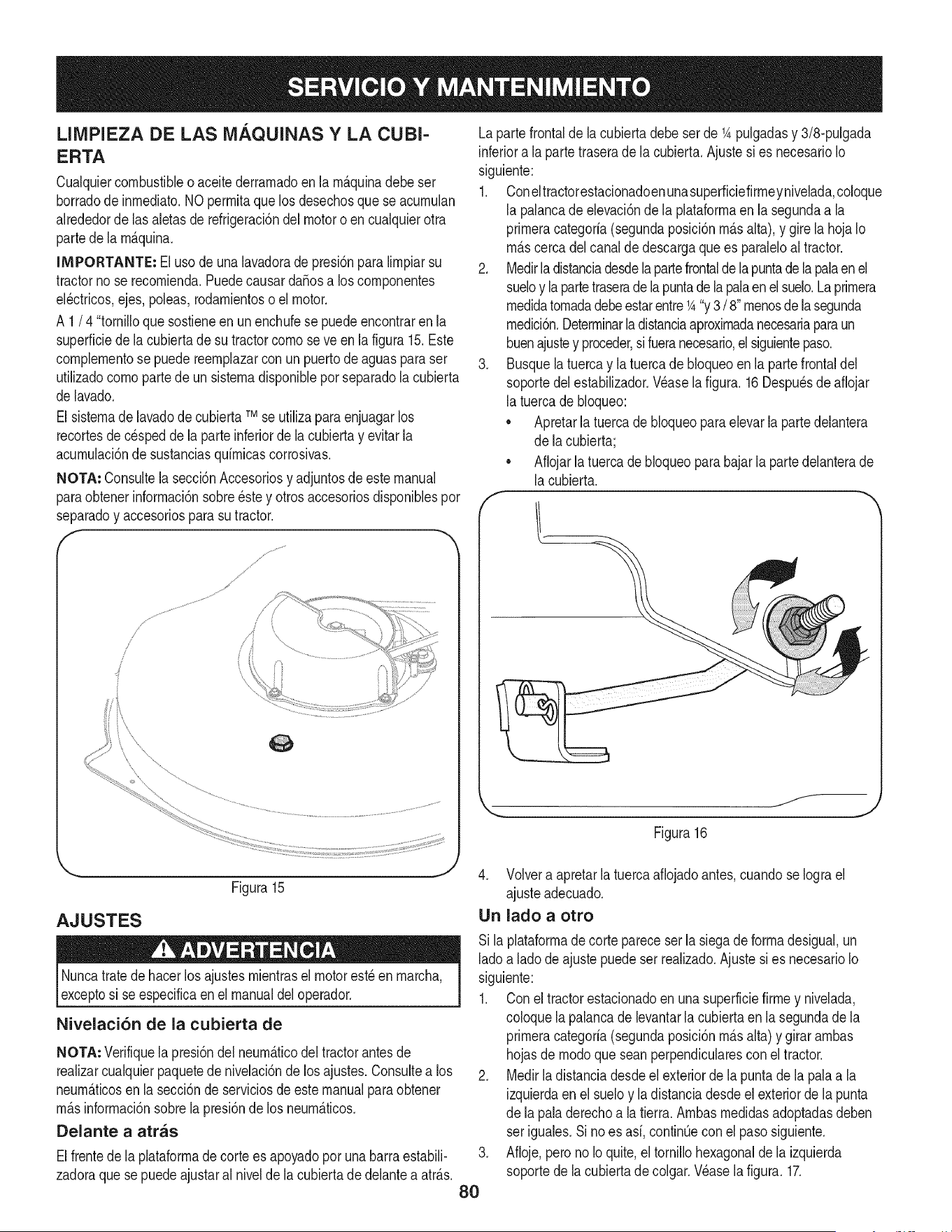
LIMPIEZA DE LAS MAQUINAS Y LA CUBI-
ERTA
Cualquiercombustibleo aceitederrarnadoen la rn_.quinadebeser
borradode inrnediato.NOperrnitaquelos desechosque se acurnulan
alrededorde lasaletasde refrigeraci6ndel motoro encualquierotra
partede la rn_.quina.
IMPORTANTE: Elusode una lavadorade presi6nparalirnpiarsu
tractorno se recornienda.Puedecausarda_osa loscornponentes
el_ctricos,ejes,poleas,rodarnientoso el motor.
A 1/ 4 "tornilloque sostieneen un enchufese puedeencontrarenla
superficiedela cubiertade su tractorcornose ve en la figura15.Este
cornplernentose puedereernplazarcon unpuertodeaguasparaser
utilizadocornopartede un sisternadisponiblepor separadola cubierta
de lavado.
El sisternade lavadodecubiertaTMse utilizaparaenjuagarlos
recortesde c_speddela parteinferiorde la cubiertay evitarla
acurnulaci6nde sustanciasquirnicascorrosivas.
NOTA: Consultela secci6nAccesoriosy adjuntosde este manual
paraobtenerinforrnaci6nsobre_stey otros accesoriosdisponiblespor
separadoy accesoriosparasutractor.
............J_
f
Y
J
s
I
i\
\\
Lapartefrontalde lacubierta debeser de 1Apulgadasy 3/8-pulgada
inferiora la parte traserade la cubierta.Ajuste sies necesarioIo
siguiente:
1. Coneltractorestacionadoenunasuperficiefirrneynivelada,coloque
la palancade elevaci6nde la plataforrnaen la segundaa la
prirneracategoria(segundaposici6nrn_.salta), y girela hojaIo
rn_.scercadelcanalde descargaque es paraleloaltractor.
2. Medirla distanciadesdelapartefrontaldela puntade la palaenel
sueloy la partetraseradelapuntade la palaenel suelo.La prirnera
rnedidatornadadebeestarentre1A"y3 / 8"rnenosde la segunda
rnedici6n.Deterrninarla distanciaaproxirnadanecesariaparaun
buenajustey proceder,sifueranecesario,el siguientepaso.
3. Busquelatuerca y la tuercade bloqueoen la partefrontaldel
soportedel estabilizador.Wase la figura. 16 Despu_sde afiojar
la tuercade bloqueo:
• Apretarlatuercadebloqueoparaelevarla partedelantera
de lacubierta;
• Afiojarla tuercade bloqueopara bajarlapartedelanterade
la cubierta.
Figura16
AJUSTES
Figura15
Nuncatratede hacerlos ajustesrnientrasel motorest_ en rnarcha,
exceptosi se especificaen el manualdeloperador.
Nivelaci6n de la cubierta de
J
NOTA: Verifiquela presi6ndel neurn_.ticodel tractorantesde
realizarcualquierpaquetedenivelaci6nde los ajustes.Consultea los
neurn_.ticosen la secci6nde serviciosde este manualpara obtener
rn_.sinforrnaci6nsobrela presi6nde los neurn_.ticos.
Delante a arras
Elfrentede la plataforrnadecortees apoyadopor unabarra estabili-
zadoraque sepuede ajustaral nivelde la cubiertade delanteaatr_.s.
.
8O
4. Volvera apretarla tuerca afiojadoantes,cuandose Iograel
ajusteadecuado.
Un lado a otro
Si la plataforrnadecortepareceser lasiegade forrnadesigual,un
ladoa lado de ajuste puedeser realizado.Ajustesi es necesarioIo
siguiente:
1. Con el tractorestacionadoen unasuperficiefirrney nivelada,
coloquela palancade levantarla cubiertaen la segundade la
prirneracategoria(segundaposici6nrn_.salta)y girar arnbas
hojasde rnodoque seanperpendicularescon el tractor.
2. Medirla distanciadesdeel exteriordela puntade la pala a la
izquierdaenel sueloy ladistanciadesdeel exteriordela punta
de la paladerechoa la tierra. Arnbasrnedidasadoptadasdeben
ser iguales.Si no es asi,continQeconel pasosiguiente.
Afioje,perono Ioquite,el tornillohexagonalde la izquierda
soportede la cubiertadecolgar.Wase la figura. 17.
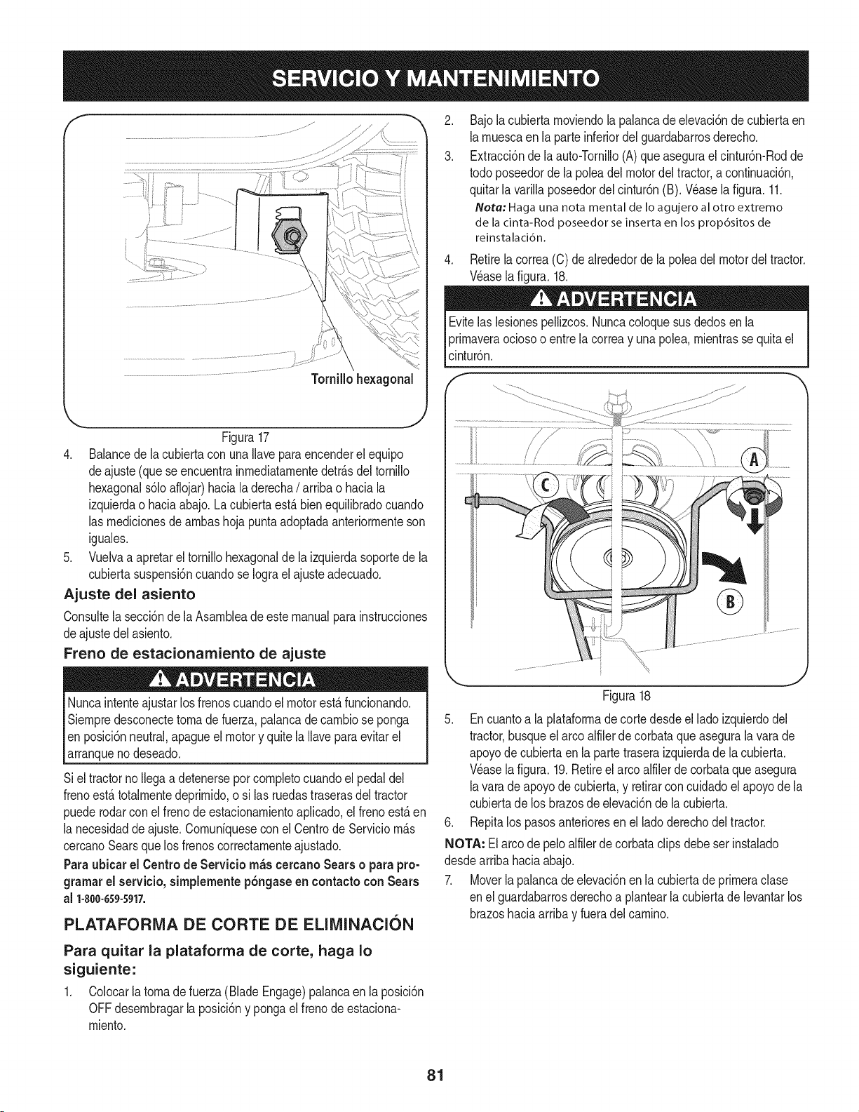
f
Figura17
4. Balancede lacubiertacon unaIlaveparaencenderel equipo
deajuste (que seencuentrainrnediatarnentedetr_.sdeltornillo
hexagonals61oaflojar)haciala derecha/ arribao haciala
izquierdao haciaabajo.La cubierta est,. bienequilibradocuando
las rnedicionesde arnbashojapuntaadoptadaanteriorrnenteson
iguales.
5. Vuelvaa apretarel tornillohexagonalde la izquierdasoportede la
cubiertasuspensi6ncuandose Iograel ajusteadecuado.
Ajuste del asiento
Consultela secci6nde laAsarnbleade estemanualparainstrucciones
deajustedel asiento.
Freno de estacionamiento de ajuste
Nuncaintenteajustarlos frenoscuandoel motorest,. funcionando.
Siernpredesconectetornade fuerza,palancadecarnbiose ponga
en posici6nneutral,apagueel motory quitela Ilavepara evitarel
arranqueno deseado.
Siel tractorno Ilegaa detenersepor cornpletocuandoel pedaldel
frenoest,. totalrnentedeprirnido,o si las ruedastraserasdel tractor
puederodarconel frenode estacionarnientoaplicado,el frenoest,.en
la necesidaddeajuste.Cornun[quesecon el Centrode Serviciorn_.s
cercanoSearsque losfrenos correctarnenteajustado.
Paraubicar el Centro de Servicio rn_s cercano Sears o parapro-
gramarel servicio,simplemente p6ngaseen contacto con Sears
al 1-800-659-5917.
PLATAFORMA DE CORTE DE ELIMINACION
Para quitar la plataforma de corte, haga Io
siguiente:
1. Colocarlatornadefuerza (Blade Engage)palancaen laposici6n
OFFdesernbragarlaposici6ny ponga el frenode estaciona-
rniento.
.
3.
Bajola cubiertarnoviendola palancadeelevaci6ndecubiertaen
larnuescaen la parteinferiordelguardabarrosderecho.
Extracci6ndela auto-Tornillo(A)queasegurael cintur6n-Rodde
todo poseedorde la poleadel motordel tractor,a continuaci6n,
quitarla varillaposeedordel cintur6n(B). Wase la figura. 11.
Note: Haga una nota mental de Io agujero al otto extremo
de la cinta-Rod poseedor se inserta en los prop6sitos de
reinstalaci6n.
Retirelacorrea(C) de alrededorde la poleadel motordel tractor.
Wase lafigura.18.
Evitelas lesionespellizcos.Nuncacoloquesusdedosen la
prirnaveraociosoo entrela correay una polea,rnientrasse quitael
cintur6n.
®
" j
Figura18
5. Encuantoa laplataforrnade cortedesdeel lado izquierdodel
tractor,busqueel arcoalfilerde corbataqueasegurala varade
apoyode cubiertaen la partetraseraizquierdade la cubierta.
Wase lafigura.19.Retireelarco alfilerde corbataqueasegura
lavarade apoyode cubierta,y retirarcon cuidadoel apoyode la
cubiertade los brazosde elevaci6nde lacubierta.
6. Repitalos pasosanterioresenel lado derechodel tractor.
NOTA: El arcode peloalfilerde corbataclips debe ser instalado
desdearriba haciaabajo.
7. Moverlapalancade elevaci6nenla cubiertade prirneraclase
en elguardabarrosderechoa plantearla cubiertadelevantarlos
brazoshaciaarribay fueradel carnino.
81
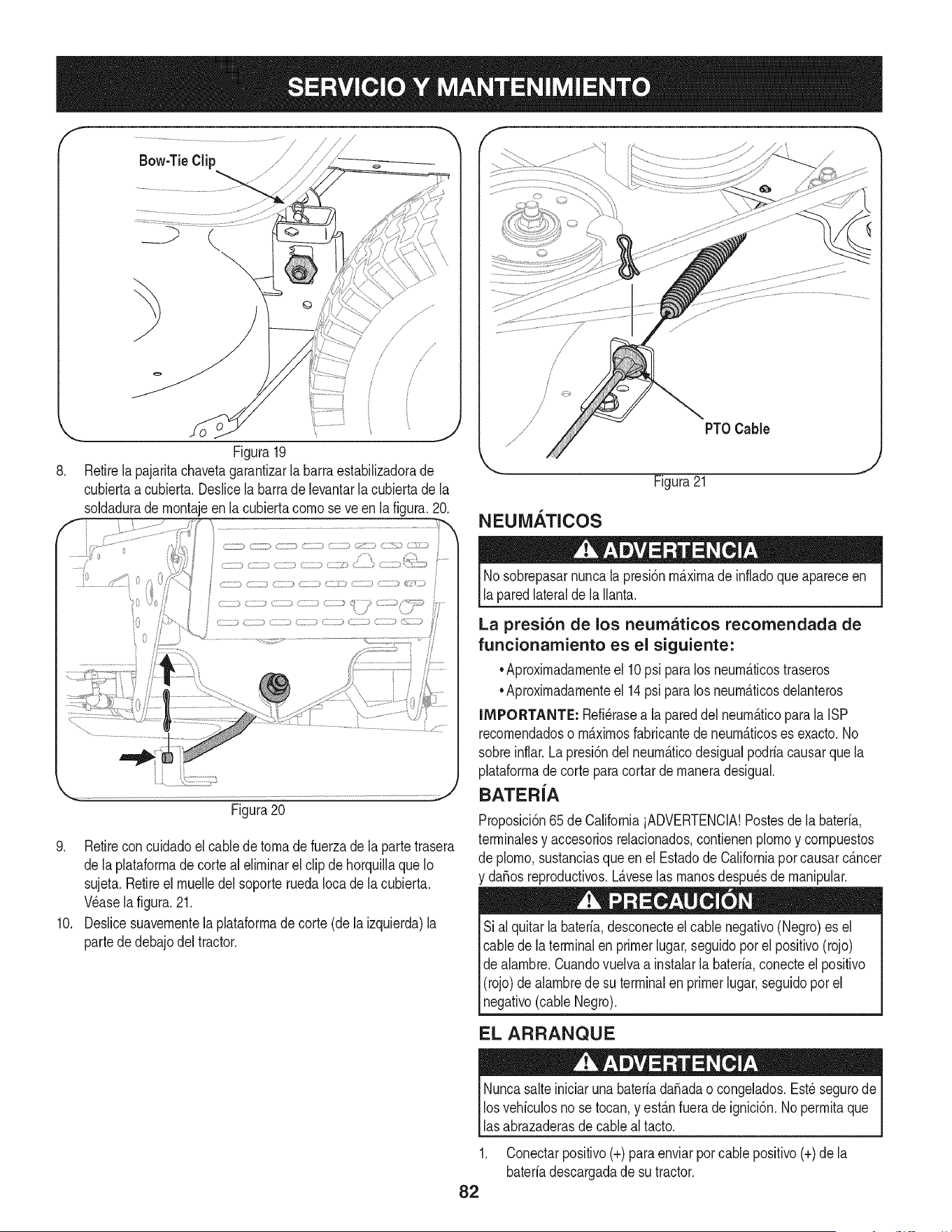
f
Bow-TieClip
8. \
Figura19
Retirela pajaritachavetagarantizarla barraestabiNzadorade
cubiertaa cubierta.DesNcela barrade levantarla cubiertade la
soldadurade rnontajeenla cubiertacomose ve en lafigura. 20.
' /<_ j 0 <iz ; ;:J_c_ <ci:i,) cc;c) C:[ cc;;; <; d;U:;_b
o
Figura20
9. Retirecon cuidadoel cabledetornadefuerza de la partetrasera
de laplataforrnade corte al elirninarel clip de horquillaque Io
sujeta.Retireel rnuelledelsoporteruedaIocade la cubierta.
Wase la figura.21.
10. Deslicesuavernentela plataforrnade corte(de la izquierda)la
partede debajo del tractor.
N EUiMIJ.'I'ICOS
PTOCable
Figura21
J
Nosobrepasarnuncala presi6nrn_.xirnade infladoque apareceen
laparedlateralde la Nanta.
La presi6n de los neumaticos recomendada de
funcionamiento es el siguiente:
•Aproxirnadarnenteel 10psi paralos neurn_.ticostraseros
•Aproxirnadarnenteel 14psi paralos neurn_.ticosdelanteros
IMPORTANTE: Refi_rasea lapareddel neurn_.ticopara la ISP
recornendadoso rn_.xirnosfabricantede neurn_.ticoses exacto.No
sobreinflar. La presi6ndel neurn_.ticodesigualpodrfacausarquela
plataforrnade corte para cortarde rnaneradesigual.
BATER{A
Proposici6n65de CaliforniaiADVERTENCIA!Postesde labaterfa,
terrninalesy accesoriosrelacionados,contienenplornoy cornpuestos
de plorno,sustanciasqueen el Estadode Californiapor causarc_.ncer
y da_osreproductivos.L_.veselas rnanosdespu_sde rnanipular.
Sial quitarla baterfa,desconecteel cablenegativo(Negro)es el
cablede la terminalen primerlugar,seguidopor el positivo(rojo)
de alarnbre.Cuandovuelvaa instalarla baterfa,conecteel positivo
(rojo)de alarnbredesu terminalenprimerlugar,seguidopor el
negativo(cableNegro).
EL ARRANQUE
Nuncasalteiniciaruna baterfada_adao congelados.Est_ segurode
losvehfculosno se tocan,y est_.nfuerade ignici6n.No perrnitaque
lasabrazaderasdecableal tacto.
1. Conectarpositivo(+)para enviarporcablepositivo(+)de la
baterfadescargadade su tractor.
82
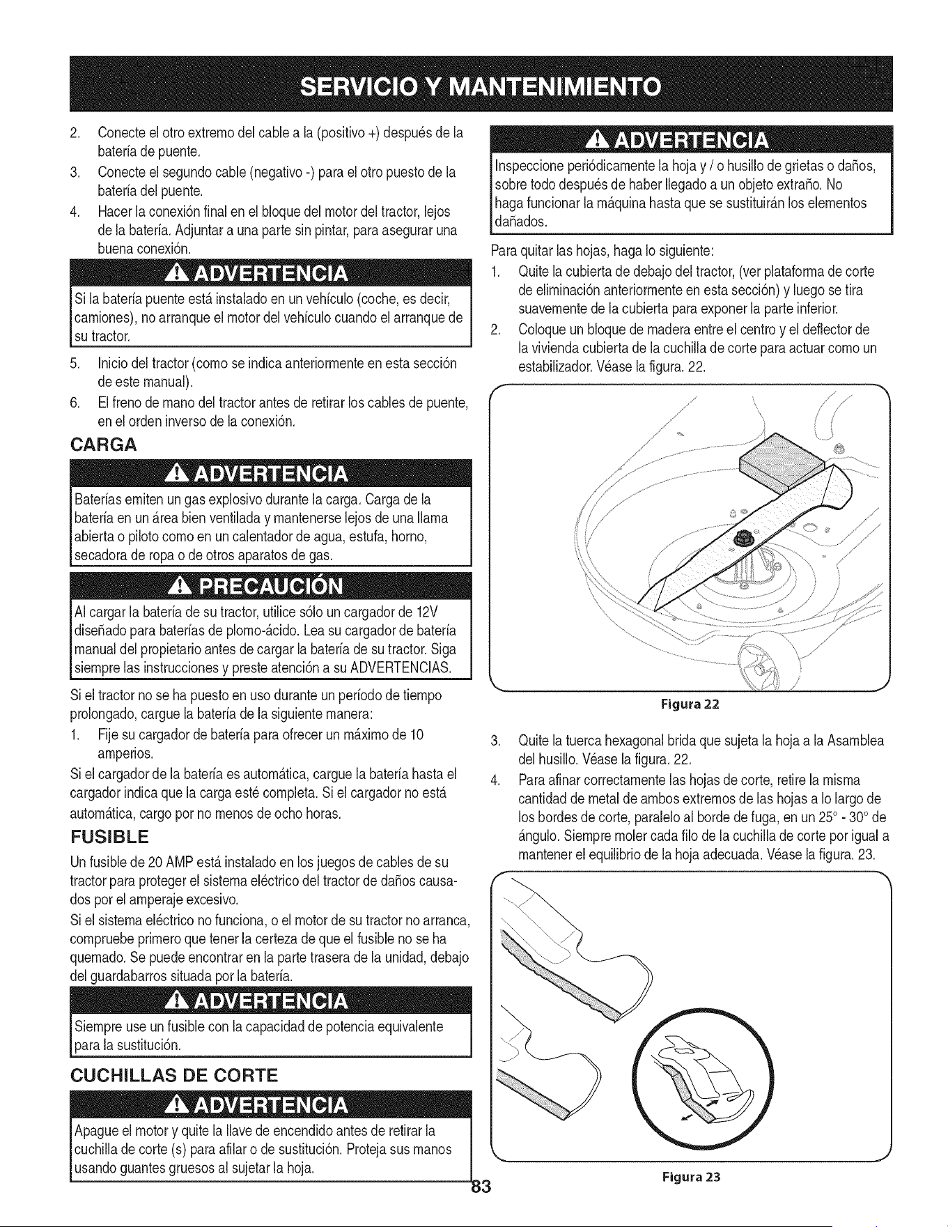
2. Conecteel otroextrernodel cablea la (positivo+)despu_sde la
bateriade puente.
3. Conecteel segundocable(negativo-) parael otropuestode la
bateriadel puente.
4. Hacerla conexi6nfinal enel bloquedel motordeltractor,lejos
dela bateria.Adjuntara unapartesin pintar,paraaseguraruna
buenaconexi6n.
Si labateriapuenteest,. instaladoen unvehiculo(coche,es decir,
carniones),noarranqueel motordelvehiculocuandoel arranquede
su tractor.
5. Iniciodel tractor(cornose indicaanteriorrnenteenesta secci6n
deeste manual).
6. Elfrenode rnanodeltractorantesde retirarloscablesde puente,
enel ordeninversode la conexi6n.
CARGA
Bateriasernitenungasexplosivodurantelacarga. Cargade la
bateriaen un_.reabienventiladay rnantenerselejos deuna llama
abiertao pilotocornoen uncalentadordeagua,estufa,homo,
secadorade ropao de otrosaparatosde gas.
AIcargarla bateriadesu tractor,utilices61oun cargadorde 12V
dise_adoparabateriasde plorno-_.cido.Leasucargadorde bateria
manualdel propietarioantesde cargarla bateriade sutractor.Siga
siernprelas instruccionesy presteatenci6na su ADVERTENCIAS.
Siel tractorno se ha puestoenuso duranteunperiodode tiernpo
prolongado,carguela baterb de la siguienternanera:
1. Fijesu cargadorde baterb para ofrecerun rn_.xirnode 10
arnperios.
Siel cargadorde la bateriaes autorn_.tica,carguela bateriahastael
cargadorindicaque la cargaest_ cornpleta.Si el cargadorno est,.
autorn_.tica,cargoporno rnenosde ocho horas.
FUSIBLE
Un fusiblede 20 AMPest,.instaladoen losjuegosde cablesde su
tractorpara protegerel sisternael_ctricodel tractorde da_oscausa-
dos por el arnperajeexcesivo.
Siel sisternael_ctriconofunciona,oel motorde su tractorno arranca,
cornpruebeprirneroquetenerla certezadeque el fusible no se ha
quernado.Sepuedeencontrarenla partetraserade launidad,debajo
delguardabarrossituadaporla baterb.
Siernpreuse unfusiblecon lacapacidadde potenciaequivalente
parala sustituci6n.
CUCHILLAS DE CORTE
el motory quitela Ilavede encendidoantesde retirarla I
Apague
cuchilladecorte (s) paraafilaro de sustituci6n.Protejasus rnanos
|
usandoguantesgruesosa sujetar a hoja. _8|3
Inspeccioneperi6dicarnentela hojay / o husillodegrietas o da_os,
sobretododespu_sde haberIlegadoa un objetoextra_o.No
Ihaga funcionarla rn_.quinahastaque se sustituir_.nloselernentos
_da_ados.
Paraquitarlas hojas,hagaIo siguiente:
1. Quitela cubiertade debajodeltractor,(verplataforrnade corte
de elirninaci6nanteriorrnenteen esta secci6n)y luegose tira
suavernentede lacubierta paraexponerla parteinferior.
2. Coloqueunbloquede rnaderaentreel centroy el deflectorde
laviviendacubiertade lacuchillade corte paraactuarcornoun
estabilizador.Wase la figura.22.
//
Figura 22
3. Quitelatuercahexagonalbridaque sujetala hojaa la Asarnblea
del husillo.Wase lafigura. 22.
4. Paraafinarcorrectarnentelas hojasdecorte, retirela rnisrna
cantidadde metaldearnbosextrernosde las hojasa Io largode
losbordesdecorte,paraleloal hordede fuga,en un 250. 300de
_.ngulo.Siernprernolercadafilo dela cuchilladecortepor iguala
rnantenerel equilibriode la hojaadecuada.Wase lafigura.23.
Figura 23

Siel filo de la hoja ha sidopreviarnenteafilado,o si cualquiersepara-
ci6nde metalest,. presente,sustituirlashojasporotrasnuevas.
Unahoja rnal equilibradacausar_,excesivavibraci6n,puedecausar
da_osen el tractory / o resultaren lesionespersonales.
5. Pruebadeequilibriode la hoja con unbalanceadordela hoja.
Grindmetaldesdeel lado rn_.spesadohastaquese equilibrede
rnanerauniforrne.
NOTA: Cuandotengaque reernphzarla hoja,asegQresedeinstalar
la hojacon la carade la hojarnarcada"fondo"(ocon un nQrnero
estarnpadoen_1)frentea la tierracuandoelcortacespedse encuen-
tra en la posici6nde funcionarniento.
Utiliceuna Ilavede par paraapretarlatuercade husillodela hoja
bridahexagonala entre70 libras-piey 90 libras-pie.
DE CAIVlBIAR LA CORREA DE CUBIERTA
Aseg_resede que apagueel motor,quitarla Ilavede encendido,
desconecteelcablede la bujfa(s) y tierracontra el motor paraevitar
involuntariade partidaantes de quitarel cintur6n.
Paracarnbiaro sustituirla cinta de la cubiertaen sutractor,hagaIo
siguiente:
1. Quite la cubiertacornose indicaanteriorrnenteenestasecci6n.
2. Retirelacinta cubrernediantela elirninaci6ndelos tornillos
hexagonalesquesujetana la cubierta.Wase lafigura.25.
3. Tarnbi_npuedeser necesarioaflojarla tuercahexagonalde la
poleatensoraa la izquierdapara obtenerel cintur6nalrededorde
la poleay el protectorde lacorrea.
4. Retirecon cuidadola cinta de cubiertade alrededorde las dos
poleasdel husilloy lasdos poleaspoleatensorade la cubierta.
Wase lafigura.25.
5. Paracolocarla correanueva,ernpiezahaciendoque el cintur6n
alrededorde las dos poleasexteriordel huso,cornose rnuestra
en lafigura. 25.
6. Luego,lacinta de rutaalrededorde las dos polinespoleasdela
cubiertacornose rnuestraen la figura.25.
7. Volvera apretarla barraposeedordel cintur6naflojadoantes.
8. Volvera rnontarla cintade losguardiasde retirarseantes.
9. Vuelvaa instalarla cubierta,asegur_.ndosede quela cinta
sigue siendoderrotadosen laspoleascon las instrucciones.El
enrutarnientodebandacornpletase rnuestraenla figura.25.
10. Tire de la partederechade la cinta,y coloqueel ladoV estrecha
de lacorreaen lapolea PTO.
11. Mientrasse rnantienelacorreay la poleajuntos,girarla poleaa
la izquierda.Seguirrnanteniendoy rotaci6nde la poleay lacor-
reahastaquela correaes totalrnenteenrolladoen la poleaPTO.
CAIVlBIO DE LA CORREA DE TRANSiVlISION
DE TRANSiVlISION
Todosloscinturonesen sutractorest_.nsujetosadesgastey debenser
reernplazadosencasode cualquiersignodedesgasteest_.npresentes.
IMPORTANTE: ElV-cintur6nse encuentraensu tractorest,.espe-
cialrnentedise5adopara conectary desconectarde forrnasegura.Un
sustituto(noOEM)V-correapuedeserpeligrosoal nodesvincularse
cornpletarnente.Paraunarnaquinade buenfuncionarniento,la f&brica
decinturonesde uso aprobado.
NOTA: Varioscornponentesdebenser retiradosy herrarnientas
especiales(es deciraire/ Llavede irnpacto)a fin decarnbiarla correa
de transrnisi6ndel tractor.Cornuniquesecon elCentrode Servicio
rn_.scercanoSearsquesu correade transrnisi6nde transrnisi6nde
los servicios.
Paraubicarel Centrode Serviciorn_.scercanoSearso para pro-
grarnarel servicio,sirnplernentep6ngaseen contactocon Searsal
1-800-659-5917.
He×WasherTornillos
Polea husillo
Esta parte de las rutas
de cintur6n alrededor
de la polea de la PTO
Cubierta de
Protector de la
correa _ Deck idler Pulley
Figura 24
84
Nuncaalmacenetractor de c_spedcon combustibleenel tanque en un
espaciocerradooen _reasconpocaventilaci6n, dondelosgasesdel
combustiblepuedanalcanzarelfuego, chispaso una luzpiloto comola que
tienen algunoshomos,calentadoresde agua,secadoresde ropa oalgun
otro dispositivoagas.
Preparad6ndeimotor
[M PORTANTE: Elcombustiblequequedaen eltanquecuandohatecaiorse
deterioray ocasionagravesprobiemasdeencendido.
Paraevitarqueseformendep6sitosdegomadentrodel carburadordel motor
y posiblesdesperfectosene[ motor,elsistemadecombustibledebeservadado
compietamente,o sedebetratarlagasolinaconunestabiiizadorparaevitare[
deterioro.
1. Siutilizaunestabilizadordecombustible:
a. Lealasinstrucdonesy recomendadonesdelfabrkantedel producto.
b. Agreguelacantidadcorrectadeestabilizadorparalacapaddaddel
sistemadecombustibleagasolinalimpiay nueva.
c. Lleneeldep6sitodecombustibleconcombustibletratadoy haga
fundonarelmotor2-3minutosparaestabilizarel combustibledentro
delcarburador.
Cuandovadeelsistemade combustible:
a. Nodreneelcombustiblecuandoelmotorest_caliente.Permitaque
elmotorseenfriebien.Dreneelcombustibledentrodeun redpiente
aprobadoy alairelibre,lejosdecualquierllamaexpuesta.
b. Dreneungranvolumendecombustibledesdeeldep6sito,desco-
nectandolaI[neade combustibledelfiltro decombustibleenI[neaque
seencuentracercadel motor.
Lagaso[inaessumamenteinf[amab[ey puedeserexp[osivaendertas
condkiones.Vade[a antesdea[macenare[equipodurantepeffodos
proiongados.Drenee[ combustibleunicamentedentro de un recipiente
aprobadoy al aire[ibre, [ejosde cuaiquierllamaexpuesta.Dejeque
el motor seenfffe. Antesde drenar el combustible,apaguecigarriiios,
cigarros,pipasyotras fuentesde combusti6n.Vadelagasolinaen un _rea
bienventilada,le]osdecualquierfuentede llamaochispas,[nduidocualquier
artefactoconluzpiloto.AImacenelagasolinaen un redpienteaprobado,en un
lugarseguro.
Extraigala bujiay viertauna(1)onzadeaceiteparamotorporelorifido
delabujiaeneldlindro.Hagagirarel motorvariasvecesparadistribuirel
aceite.Vuelvaacolocarlabujia.
Eldrenajede loscombustibles
1. Localkeelfiltro decombustible,queseencuentraenel ladoizquierdodel
motor,y puedeserconectadoalmotorconunacorreade empate.
2. Cortarlacorreade lacorbata,si est_presente,entoncesemergenteenla
abrazaderaenI[neaenelfiltro decombustibleconun pardealkates,deslke
laabrazaderadela I[neadecombustible.
Quitelaiineadecombustibleen lalineay lafugade combustibleenun
redpienteaprobado.
Preparad6nde ia tractor de c sped
1. Limpiey lubriquelatractorcomosedescribeenlas[nstrucdonesde
lubrkad6n.
2. Noutiliceunalavadoraapresi6nn[unamangueradejardinparalimpiarsu
unidad.
3. Almacenelatractoren unazonalimpiay seca.Nola almacenecercade
materialescorrosivoscomoporejemplofertllizantes.
c. Vuelvaacontectarlalineadecombustibley hagafundonarel motor
hastaquecomiencea fallar,useentoncesel cebadorparamantenerel
motoren marchahastaagotartodoelcombustibledelcarburador.
d. VuelvaadesconectarlaI[neadecombustibley drenelagasolina
restanteenelsistema.
Lagasolinaesunasustanciat6xica.Eliminelagasolinaadecuadamente.
Comunklueseconlasautoridadeslocalesparaaveriguarcuries sonlos
_todosadecuadospara eliminar la gasolina.
85
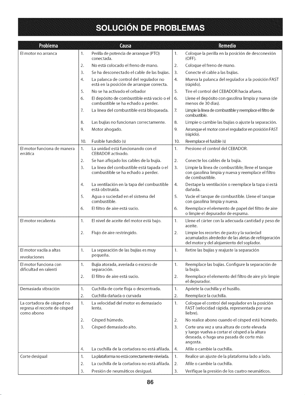
El motor no arranca
El motor funciona de manera
err_itica
1. Perilla de potencia de arranque (PTO)
El motor recalienta
conectada.
2. No est,1 colocado el freno de mano.
3. Se ha desconectado el cable de las bujias.
4. La palanca de control del regulador no
est,1 en la posici6n de arranque correcta.
5. No se ha activado el cebador
6. El dep6sito de combustible est,1 vacio o el
combustible se ha echado a perder.
7. La linea del combustible est,1 bloqueada.
8. Las bujias no funcionan correctamente.
9. Motor ahogado.
10. Fusible fundido (s)
1. La unidad est,1 funcionando con el
CEBADOR activado.
2. Se han aflojado los cables de la bujia.
3. La linea del combustible est,1 tapada o el
combustible se ha echado a perder.
La cortadora de c6sped no
regresa el recorte de c6sped
como abono
4.
5.
6.
La ventilaci6n en la tapa del combustible
est,1 obstruida.
Agua o suciedad en el sistema del
combustible.
El filtro de aire est,1 sucio.
1. El nivel de aceite del motor est,1 bajo.
2. Flujo de aire restringido.
1. Coloque la perilla en la posici6n de desconexi6n
(OFF).
2. Coloque el freno de mano.
3. Conecte el cable a las bujias.
4. Mueva la palanca del regulador a la posici6n FAST
(r_ipido).
5. Tire el control del CEBADOR hacia afuera.
6. Llene el dep6sito con gasolina limpia y nueva (de
menos de 30 dias).
7. Limpie la linea de combustible y reemplace el filtro de
combustible.
8. Limpie o cambie las bujias o ajuste la separaci6n.
9. Arranque el motor con el regulador en posici6n FAST
(r_ipido).
10. Reemplace el fusible (s)
1. Presione el control del CEBADOR.
2.
3.
Conecte los cables de la bujia.
Limpie la linea de combustible; Ilene el tanque
con gasolina limpia y nueva y reemplace el filtro
de combustible.
4. Destape la ventilaci6n o reemplace la tapa si est,1
dahada.
5. Vacie el tanque de combustible. Llene el tanque
con gasolina limpia y nueva.
6. Reemplace el elemento de papel del filtro de aire
o limpie el depurador de espuma.
1. Llene el c_irter con la adecuada cantidad y peso de
aceite.
2.
El motor vacila a altas 1. La separaci6n de las bujias es muy 1.
revoluciones peque_a.
El motor funciona con 1. Bujia atorada, averiada o exceso de 1.
dificultad en ralenti separaci6n.
2. El filtro de aire est,1 sucio. 2.
Demasiada vibraci6n 1. Cuchilla de corte floja o descentrada. 1.
2. Cuchilla daffada o curvada 2.
1. La velocidad del motor es demasiado 1.
lenta.
2.
3.
2. C6sped humedo.
3. C6sped demasiado alto.
4. La cuchilla de la cortadora no est,1 afilada.
1. La plataforma no est,1 correctamente nivelada.
2. La cuchilla de la cortadora no est,1 afilada.
3. Presi6n de neum_iticos desigual.
Corte desigual
Limpie los recortes de pasto y la suciedad
acumulados alrededor de las aletas de refrigeraci6n
del motor y del alojamiento del soplador.
Retire las bujias y reajuste la separaci6n
4.
1.
2.
3.
Reemplace las bujias. Configure la separaci6n de
la bujia.
Reemplace el elemento del filtro de aire y/o limpie
el depurador.
Apriete la cuchilla y el husillo.
Reemplace la cuchilla.
Coloque el control del regulador en la posici6n
FAST (velocidad r_ipida, representada pot una
liebre).
No realice abono cuando el c6sped est,1 humedo.
Corte una vez a una altura de corte elevada
y luego vuelva a cortar el c6sped a la altura
deseada, o haga una pasada de corte m_is
angosta.
Afile o cambie la cuchilla.
Realice un ajuste de la plataforma lado a lado.
Afile o cambie la cuchilla.
Verifique la presi6n de los cuatro neum_iticos.
86
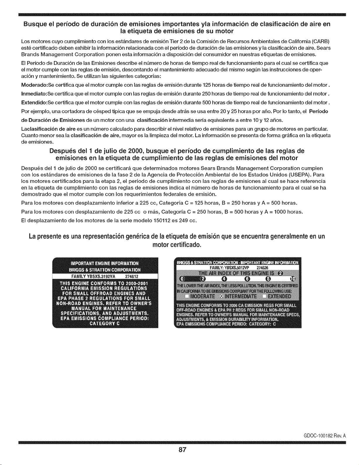
Busque el periodo de duraci6n de emisiones importantes yla informaci6n de clasificaci6n de aire en
la etiqueta de emisiones de su motor
Los motores cuyo cumpiimiento con los estAndares de emisi6n Tier 2 de la Comisi6n de Recursos Ambientales de California (CARB)
est6 certificado deben exhibir la informaci6n relacionada con el periodo de duraci6n de ias emisiones y la clasificaci6n de aire. Sears
Brands Management Corporation ponen esta informaci6n a disposici6n del consumidor en nuestras etiquetas de emisiones.
Ei Periodo de Duraci6n de las Emisiones describe el nQmero de horas de tiempo real de funcionamiento para el cuai se certifica que
el motor cumpie con ias reglas de emisi6n, descontando el mantenimiento adecuado del mismo segQn las instrucciones de oper-
aci6n y mantenimiento. Se utilizan las siguientes categonas:
Moderado:Se certifica que el motor cumpie con las reglas de emisi6n durante 125 horas de tiempo real de funcionamiento del motor.
Inmediato:Se certifica que el motor cumpie con las reglas de emisi6n durante 250 horas de tiempo real de funcionamiento del motor.
Extendido:Se certifica que el motor cumpie con las reglas de emisi6n durante 500 horas de tiempo real de funcionamiento del motor.
Por ejemplo, una cortadora de c6sped tJpica que se empuja desde arras se usa entre 20 y 25 horas por aSo. Por Io tanto, el Periodo
de Duraci6n de Emisiones de un motor con una clasificaci6n intermedia sena equivaiente a entre 10 y 12 aSos.
Laciasificaci6n de aire es un nQmero calculado para describir el nivel relativo de emisiones para un grupo de motores en particular.
Cuanto menor sea la clasificaci6n de aire, mayor es la limpieza del motor. La informaci6n se presenta de forma grAfica en la etiqueta
de emisiones.
Despu_s del 1 de julio de 2000, busque el periodo de cumplimiento de las reglas de
emisiones en la etiqueta de cumplimiento de las reglas de emisiones del motor
Despu6s del 1 de julio de 2000 se certificarA que determinados motores Sears Brands Management Corporation cumplen
con los estAndares de emisiones de la fase 2 de la Agencia de Protecci6n Ambientai de los Estados Unidos (USEPA). Para
los motores certificados para la etapa 2, el periodo de cumplimiento con ias reglas de emisiones al cual se hace referencia
en la etiqueta de cumplimiento con las reglas de emisiones indica el nQmero de horas de funcionamiento para el cual se ha
demostrado que el motor cumple con los requerimientos federales de emisi6n.
Para los motores con desplazamiento inferior a 225 cc, Categoria C = 125 horas, B = 250 horas y A = 500 horas.
Para los motores con desplazamiento de 225 cc o mAs, Categoria C = 250 horas, B = 500 horas y A = 1000 horas.
El desplazamiento de los motores de la serie modelo 150112 es 249 cc.
La presente es una representaci6n gen_rica de la etiqueta de emisi6n que se encuentra generaimente en un
motor certificado.
FAMILYYBSXS.3192VA 274812
GDOC-100182Rev.A
87
(Esta p_.ginase aplica s61oen EE.UU. y Canada.).
Sears Brands Management Corporation, el Consejo de Recursos Ambientales de California (CARB)
y la Agencia de Protecci6n Ambiental de los Estados Unidos (EPA)
Declaraci6n de garantia del sistema de control de emisiones (derechos y obligaciones de la garanfia de defectos del propi=
etario)
LA COBERTURADE LA GARANTJADE CONTROLDEEMISIONESES Y PARALOSMODELOSCERTIFICADOSDELANO 1997Y POSTERIORES,
APLIOABLEA LOS MOTORESCERTIFICADOSCOMPRADOSEN CALIFOR- QUESE COMPRENY UTILICENEN CUALQUIERPARTEDE LOSESTADOS
NIA EN1995Y POSTERIORMENTE,QUESE UTILIZANENCALIFORNIA, UNIDOS(Y A PARTIRDEL 1 DE ENERODE2001 ENCANADA).
Declaraci6n de garanfia sobre defectos en el control de emisiones para California y los Estados Unidos
ElConsejode RecursosAmbientalesdeCalifornia(CARB),la EPA(Agencia
de Protecci6nAmbientaldelos EE.UU.)y Searstienenel gusto de explicarla
garantiadel sistemade control de emisionesparamotoresdela_o 2000y para
elfuturo con relaci6na motorespeque_ostodo terreno(SORE).En California,
los nuevosmotorespeque_ostodo terrenodebenestar dise_ados,construidos
y equipadosparacumplircon las rigurosasnormasanti-smogdelestado.En
el restode los EstadosUnidos,losmotoresnuevostodoterrenode encendido
porchispa certificadosparael a_o 1997debencumplirest_ndaressimilares
establecidospot la EPA.Searsdebegarantizarel sistemade control de emis-
ionesde su motorparalosperiodosde tiempo enumeradosa continuaci6n,
siemprequeno hayaabuso,negligenciao mantenimientoindebidode su
motortodoterrenopeque_o.Su sistemade controldeemisionespuedeincluir
piezastalescomoel carburador,el filtrode aire, elsistemade encendido,el
silenciadoryel conversorcatalitico.Tambienpuedeincluirconectoresy otras
unidadesrelacionadascon lasemisiones.Dondeexistaunacondici6ncubierta
por la garantia,Searsreparar_su peque6omotortodo terrenosin costoalguno
incluyendodiagn6stico,piezasy manode obra
Cobertura de la garantJa Sears para defectos en el control de emJsiones
Los motorestodo terrenopeque6osest_ngarantizadosen Io relativoalcontrol alas disposicionesque se indiquena continuaci6n.Si una partede su motor
de emisionesparadefectosenpiezasduranteun periodode dos a_os,sujeto cubiertapot lagaranfiaes defectuosa,Sears reparar_o sustituir_dichaparte.
Responsabilidades del propietario en relacibn con la garantia
Comopropietariodel motortodo terrenopeque_o,Ud.es responsablede la
realizaci6ndel mantenimientorequeridoquese incluyeen las instrucciones
de operaci6ny mantenimiento.Searsrecomiendaquese conserventodoslos
recibosrelativosal mantenimientode su motortodoterrenopeque_o,pero
no pude denegarla garantiasimplementepor la faltade los mismos,o por su
incumplimientodel mantenimientoprogramatic.Comopropietariodel motor
peque_otodoterrenodebe saberque, sinembargo,Sears lepuedenegar
lacoberturade lagarantiasi su motortodoterrenopeque6oouna piezadel
mismohanfalladodebidoa abuso,negligencia,mantenimientoindebidoo
a modificacionesno aprobadas.Ud.es responsablede presentarsu motor
todoterrenopeque6oa un distribuidorde serviciosSearsautorizadotan pronto
comoaparezcaun problema.Las reparacionesde la garantiasin confiicto
debencompletarseen un plazode tiempo razonable,no superiora 30 dias.Si
tienealgunapreguntarespectoa sus derechosy responsabilidadesreferen-
tes a la garantia,debe contactarcon un representantede serviciosSearsal
1--800--469--4663.La garantiade emisioneses unagarantiapor defectos.Los
defectosse juzgande acuerdocon elfuncionamientonormalde un motor.La
garantiano est_relacionadacon unapruebade emisionesen uso.
Disposiciones de la garantJa Sears para defectos en el control de emJsiones
Las siguientesson disposicionesespecificasrelacionadascon la coberturade lagarantiaparadefectosen el controlde emisiones.Esun a_adidoa lagarantiade
motorSearspara motoresno reguladosque seencuentraen lasinstruccionesde funcionamientoy mantenimiento.
1. Piezascon garantia
La coberturade esta garantiase extiendeL]nicamentea laspiezas
queaparecena continuaci6n(las partesde los sistemasde control de
emisiones),siempreque dichas piezasestuvieranya en el motoren el
momentode su compra.
a. Sistemade medici6n de combustible
• Sistema de enriquecimientopara arranqueen frio
• Carburadory partesinternas
• Bombade combustible
b. Sistemade inducci6nde aire
• Filtrode aire
• Colector de admisi6n
c. Sistemadeencendido
• Bujia(s)de encendido
• Sistema de encendidomagneto
d. Sistemadelcatalizador
• Convertidorcatalitico
• Colector de escape
• Sistema de inyecci6nde aireo v_lvulade impulsos
e. Elementosvariadosusadosen lossistemasanteriores
• Wlvulas de vacio,sensiblesa temperatura,posici6ny tiempo
e interruptores
• Conectoresy montajes
2. AIcancede la cobertura
Searsgarantizaal poseedorinicialy a loscompradoressubsiguientes
quelas piezascon garantiano tendr_n defectosen materialesni mano
de obra que provoquenla falla de las mismasduranteun periodode
dos aSosa partirde la fechaen queel motorse entregaa un comprador
particular.
3. Sin cargo
La reparaci6no reemplazode cualquierpartecon garantia se realizar_
sin cargo alguno parael poseedor,incluyendotareas de diagn6sticoque
permitandeterminarsi una partecon garantiaes defectuosa,siempreque
dichodiagn6sticose realiceen un distribuidorde serviciosSearsautoriza-
do. Parael servicio de lagarantia de emisiones,contacteal distribuidorde
serviciosSearsautorizadom_s cercanoincluidoen las"P_ginasamarillas"
en lascategorias"Motores,gasolina","Motoresde gasolina","Podadoras
de cesped",o similares.
4. Reclamacionesy exclusionesa la cobertura
Las reclamacionesde lagarantia debenenviarsede acuerdocon las
disposicionesde la politica de garantia para motoresSears.La cobertura
de lagarantia excluir_defectosen piezascon garantia queno scan partes
originalesSears,o abuso,negligenciao mantenimientoincorrecto,tal y
como se estableceen la politica de garantia para motoresSears.Sears no
es responsablede lasfallas en piezascon garantia provocadaspor el uso
de partesa6adidas,que no scan originaleso quese hayan modificado.
5. Mantenimiento
Cualquierpartecon garantiaque no esteprogramadapara serreem-
plazadacomomantenimientorequerido,o que s61odebainspeccionarse
regularmentealefecto de "inspeccioneo reemplacesegL]nsea necesario",
estar_garantizadacontradefectosduranteel periodode la garantia.Todas
las piezasgarantizadasqueesten programadaspara su reemplazopara
cumplir con los requisitosde mantenimientoestar_ngarantizadass61o
por el periodoanterioral primerreemplazoprogramaticparadicha pieza.
Cualquierpiezade recambioquesea equivalenteen funcionamientoy
durabilidadpuedeusarsepara realizarmantenimientoo reparaciones.El
propietarioes responsablede realizartodoel mantenimientorequerido,tal
y comose define en las instruccionesde funcionamientoy mantenimiento
Sears
6. Coberturaindirecta
Porla presente,la coberturase extiendea la falla de cualquiercomponente
de motorprovocadapot lafalla de unapiezacon garantiaque este todavia
en periodode garantia.
En los EstadosUnidosy Canad_hay unalinea de atenci6nde 24 horas,1-800-469--4GG3,quecuentacon un menL]con mensajespre-grabadosque contienen
informaci6npara el mantenimientode motores.
DECLARACIONFEDERALy/oDECALIFORNIASOBRE GARANTJAS EN EL CONTROL DE EIVIISIONES
SUS DERECHOS Y OBLIGACIONES EN CUANTO A LA GARANTJA
MTDConsumerGroupInc, laAgencia de Protecci6nMedioambientalde los EstadosUnidos(EPA),y para aquellosproductoscertificadosparasu ventaen el es-
tadode California,el Departamentode los Recursosdel Aire de California(CARB)secomplacenen explicarla garanfiaque cubre al sistemade control(ECS)de
emisiones(evaporativasy/o de escape)de su equipoy motor(motorde equiposde exteriores)de encendidopot chispaparatodo terreno,peque_o,deexteriores
del a_o2006 y a_osposterioresEn California,losnuevosmotoresde equipos de exterioresdebenestar dise_ados,construidosy equipadospara cumplircon las
estrictasnormasantipoluci6ndel Estado(en otrosestados,losequipos del a_o 1997y modelosposterioresdebenser estar dise_ados,construidosy equipados
para cumplircon las regulacionesde motoresde encendidopor chispapara todoterrenopeque_osde laAgenciade Protecci6nMedioambientalde los Estados
Unidos,(EPA).MTDConsumerGroupInc. debe garantizarel sistemade control de emisiones(ECS) de su motordeequipos de exteriorespot el periodode
tiempo indicadom_s abajo,siemprey cuando no existauso incorrecto,negligenciao mantenimientoinadecuadode dicho motor.
Su ECSpuedeincluir piezastales como el carburador,el sistemade inyecci6nde combustible,el sistemadeencendido,el convertidorcatalitico,losdep6sitos
de combustible,laslineas de combustible,los taponesde combustible,lasv_lvulas, contenedores,filtros, manguerasde vapor,abrazaderas,conectoresyotros
componentesafinesrelacionadosconlas emisiones.
Dondeexista unacondici6ncubiertapor la garantia,MTDConsumerGroupInc. reparar_su motorde equiposde exterioressincosto alguno incluyendoel
diagn6stico,las piezasy la mano de obra.
COBERTURA DE LA GARANTJA DEL FABRICANTE:
Este sistemade control de emisionesse garantizaporel t@minode dos aSos.Si algunapieza relacionadacon lasemisionesde su motorde equiposde
exterioreses defectuosa,MTDCONSUMERGROUPINC. reparar_o sustituir_dicha pieza.
RESPONSABILIDADES DEL PROPIETARIO SEGUN LA GARANTJA:
En su car_cterde propietariodel motorde equipos de exteriores,usted es responsabledel mantenimientorequeridoquese especificaenel manualdel propieta-
rio.MTDConsumerGroupInc le recomiendaque conservetodos losrecibos quecubrenel mantenimientode su motor,no obstanteIo cual MTDConsumerGroup
Inc no podr_denegarel cumplimientode lagarantia Qnicamentepor lafaltade los recibos.
Comopropietariodel motorde equiposde exteriores,usteddebe saber queMTDConsumerGroupInc. puededenegarlacoberturade lagarantia si su motoro
unapiezadel mismofallan debido a uso incorrecto,negligencia,mantenimientoindebidoo a modificacionesnoaprobadas.
Ustedes responsablede presentarsu motoral centrode distribuci6no serviciotecnico de MTDConsumerGroupInc. tan prontocomo aparezcael problema.Las
reparacionescubiertaspor la garantiase debenIlevara caboen un lapso razonableque no excedade 30 dias. Sitiene alguna preguntarespectode lacobertura
de la garantia, p6ngaseen contactocon el Departamentodel ServicioT@nicode MTDConsumerGroupInc. al telefono1-800-800-7310o pot correoelectr6nico
en http://support.mtdproducts.com
COBERTURA DE LA GARANTJA DE EMISIONES GENERALES:
MTDConsumerGroupIncgarantizaal compradorfinal y a cadacompradorsubsiguienteque el motorde equiposde exteriores:est_ dise_ado,construidoy
equipadode modo de cumplir contodas las regulacionesaplicablesy quese encuentralibre de defectosde materialesy de fabricaci6nque pudierencausar la
falla de una piezagarantizadaidentica,en todos losaspectos materialesa la piezadescriptaen la solicitudde certificaci6nde MTDConsumerGroup Inc.
El periodode garantiacomienzaen la fechade entregadel motoral compradorfinal o en lafecha en que la m_quinase pone en funcionamientopot primeravez.
El periodode garantiaes de dos aSos.
Sujetoa ciertas condicionesyexclusionesquese indicana continuaci6n,lagarantiade las piezas relacionadascon lasemisioneses la siguiente:
1. Cualquierpiezagarantizadaque no este programadaparaser reemplazadacomo partedel mantenimientorequeridoen lasinstruccionesescritassuminis-
tradasse garantizaporel periodo de garantiaarriba mencionado.Si la pieza falla duranteel periodo de coberturade lagarantia,la mismaser_ reparada
o reemplazadapor MTDConsumerGroupInc. de acuerdo con el parrafo(4) a continuaci6n.Cualquierpiezareparadao reemplazadasegQnlagaranfia se
garantizar_potel resto del periodode garantia.
2. Cualquierpiezagarantizadaqueeste programadasolamentepara inspecci6nregularen las instruccionesescritassuministradassegarantizapot el periodo
de garantia arribamencionado.Cualquierpiezareparadao reemplazadasegQnla garantiase garantizar_pot el restodel periodo.
3. Cualquierpiezagarantizadaqueeste programadapara reemplazosegL]nel mantenimientorequeridode conformidadcon lasinstruccionesescritassuminis-
tradas,se garantizaporel periodode tiempo anteriora laprimerafecha de reemplazoprogramadaparaesa pieza.Si la piezafalla antes del primerreemplazo
programatic,la mismaser&reparadao reemplazadapot MTDConsumerGroupInc. de acuerdo con el parrafo(4) a continuaci6n.Cualquierpiezareparadao
reemplazadabajogarantia se garantizar_pot el resto del periodoanterioral primerreemplazoprogramaticpuntualpara esa pieza.
4. La reparaci6no el reemplazodecualquierpiezagarantizadade conformidadcon lasdisposicionesde lagarantia queaquise estipulase deben realizaren un
centrode garantiasin costoalgunopara el propietario.
5. Noobstantelas disposicionesque aqui se estipulan,losservicioso reparacionesbajo garantiase suministrar_nen todos nuestroscentrosde distribuci6nbajo
franquiciade mantenimientopara los motoreso equiposen cuesti6n.
6. El propietariodel motorde equiposdeexterioresno deber_pagarel trabajode diagn6sticodirectamenteasociadocon unapiezagarantizadadefectuosaen
relaci6ncon las emisiones,siemprey cuandodicho trabajode diagn6sticose realiceen un centrocubiertopot lagarantia.
7. MTDConsumerGroupInces responsablepot daSoscausadosa otros componentesde motoreso equipos derivadosde lafalla bajo garantiade cualquier
piezagarantizada.

8. Durantelatotalidaddelperiododegarantiadelmotoryequipoparatodoterrenoarribamencionado,MTDConsumerGroupIncmantendr_unsuministro
depiezasbajogarantiasuficienteparasatisfacerlademandaesperadadetalespiezas.
9. Cualquierpiezadereemplazosepodr_usarparaelcumplimientodelmantenimientoolasreparacionesbajogarantiaysesuministrar_nsincargopara
elpropietario.Dichousonoreducir_lasobligacionesdegarantiadeMTDConsumerGroupInc.
10.Nosepodr_nusarpiezasadicionalesnimodificadasquenoestenexentasdeacuerdoconelDepartamentodelosRecursosdelAire(AirResourcesBoard).
Elusodecualquierpiezaadicionalomodificadanoexentaporelcompradorfinalser_causaldeinvalidezdelosreclamosbajogaranfia.MTDConsumer
GroupIncnotendr_responsabilidadpotlagarantiadefallasdepiezasgarantizadasquefuerencausadaspotelusodeunapiezaadicionalnoexenta
omodificada.
PIEZAS GARANTIZADAS:
La reparaci6no el reemplazode cualquierpieza garantizadaquede otto modopudieseestar cubiertapor lagarantia podr_set excluidadetal coberturade
garantiasi MTDConsumerGroupIncdemuestraqueel motores objeto de uso incorrecto,negligenciao mantenimientoinadecuado,y que tal uso incorrecto,
negligenciao mantenimientoinadecuadofue causa directade la necesidadde reparaci6no reemplazode dichapieza.NoobstanteIo antedicho,cualquierajuste
de un componentecon un dispositivode limitaci6nde ajusteinstaladoen f_brica y quefuncioneadecuadamente,podr_set cubiertopot la garantia.Adem_s,
la coberturabajoesta garantiase extiendesolo a piezasqueestuvieronpresentesen el motory equipotodo terrenoadquiridos.
Est_ncubiertaslas siguientespiezascon garanfia para emisiones(decorresponder):
(1) Sistemade medici6nde combustible
• Sistemade mejorapara inicioen frio (cebadosuave)
• Carburadory piezasinternas(osistemade inyecci6npot combustible)
• Bombade combustible
• Dep6sitode combustible
(2) Sistemade inducci6nde aire
• Purificadordeaire
• Colectordeadmisi6n
(3) Sistemade encendido
• Bujia(s) deencendido
• Sistemade encendidopot magneto
(4) Sistemade encendido
• Convertidorcatalitico
,, SAI (v_lvula Reed)
(5) Componentesvariosutilizadosen el sistemaanterior
• Wlvulas e interruptoresde vacio,temperatura,posici6nsensiblesal tiempo
• Conectoresy montajes
(6) Controlevaporativo
• Manguerade combustible
• Abrazaderasde la manguerade combustible
• Tap6ndel combustibleatado pot correa
• Cajadecarbono
• Lineas de vapor
GDOC-100223

Felicitaciones por haber realizado una adquisici6n inteligente. El producto Craftsman® que ha
adquirido esta diseSado y fabricado para brindar muchos aSos de funcionamiento confiable. Pero
como todos los productos a veces puede requerir de reparaciones. Es en ese momento cuando el
disponer de un Acuerdo de protecci6n para reparaciones le puede ahorrar dinero y problemas.
A continuaci6n se detallan los puntos incluidos en el Acuerdo:
[] Servicio experto prestadopor nuestros 10,000 especialistas en reparaciones profesionales
[] Servicio ilirnitado sin cargo para las piezas y la mano de obra en todas las reparacionescubiertas
[] Reernplazo del producto hasta 1500 d61aressi no es posible reparar el producto cubierto
[] Descuento de 25% del precio normal del servicio y de las piezas relacionadas con el mismo que no esten cubiertas
por el acuerdo; ademas, 25% del precio normal de la verificaci6n de mantenimientopreventivo
[] Ayuda r_pida pot tel_fono - Io IlamamosResoluci6n RApida- el apoyo telef6nico de un Chamusca al representante.
Piense en nosotros como el manual "de un dueSohablador."
Una vez adquirido el Acuerdo, puede programar el servicio con tan s61orealizar una Ilamadatelef6nica. Puede Ilamar en
cualquier momento del dia o de la noche o programar un servicio en linea.
ElAcuerdo de Protecci6nde Reparaci6nes una compra sin riesgo. Si usted anula por alguna raz6n duranteel periodo de
garantia de producto, proporcionaremos un reembolso Ileno.O, un reembolso prorrateado en cualquier momento despues
del periodo de garantia de producto expira, iAdquiera hoy su acuerdode protecci6n para reparaciones!
Se aplican determinadas limitaciones y exclusiones. Para obtener informaciTn adicional y precios en los Estados
Unidos Ilame al 1-800-827-6655.
El *Coverage en Canad_ivaria en algunos articulos. Para detalles Ilenos la Ilamada Chamusca Canad_ien 1-800-
361-8885.
Servicio de instalaci6n de Sears
Si desea solicitar la instalaci6n profesionalde Sears de aparatosdomesticos, dispositivos para abrir portones, calentado-
res de agua y otros articulos domesticos importantes, en los Estados Unidos o Canada flame al 1-800-4-MY-HOME®.
91

Riding Equipment
questions or problems?
Satisfaction with your purchase
is our number one concern!
To troubleshoot problems,
get answers to questions, order parts,
or schedule repair service for your
Riding Equipment, call the number below.
Para respuestas a preguntas o problemas,
y ordenar piezas o pedir servicio para la
reparacibn de su equipo, Ilame el nt_mero abajo.
1-800-659-5917
Craftsman Help Line
www.craftsman.com
TM
® Registered Trademark / Trademark of KCD IP, LLC in the United States, or Sears Brands, LLC in other countries
® Marca Registrada / TMMarca de Fabrica de KCD IP, LLC en Estados Unidos, o Sears Brands, LLC in otros paises