Owner's Manual
JCRHFTSMI N°J
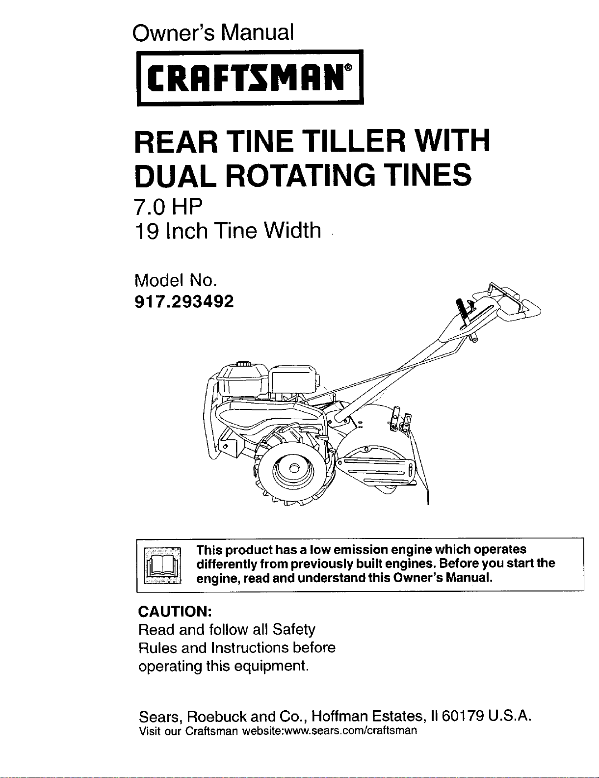
REAR TINE TILLER WITH
DUAL ROTATING TINES
7.0HP
19 Inch Tine Width
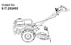
Model No.
917.293492
This product has a low emission engine which operates
differently from previously built engines. Before you start the
engine, read and understand this Owner's Manual.
CAUTION:
Read and follow all Safety
Rules and Instructions before
operating this equipment.
Sears, Roebuck and Co., Hoffman Estates, II 60179 U.S.A.
Visit our Craftsman website:www.sears.com/craftsman
Warranty ............................................... 2
Safety Rules ......................................... 2
Product Specifications .......................... 4
Assembly .............................................. 5
Operation .............................................. 8
Maintenance ....................................... 14
Maintenance Schedule ...................... 14
Service and Adjustments .................... 16
Storage ............................................... 20
Troubleshooting ................................. 21
Illustrated Parts List ............................ 44
Sears Service ...................... Back Cover
LIMITED TWO YEAR WARRANTY ON CRAFTSMAN TILLER
For two (2) years from date of purchase, when this Craftsman Tiller is maintained,
lubricated, and tuned up according to the operating and maintenance instructions in
the owner's manual, Sears will repair free of charge any defect in material or workman-
ship.
This Warranty does not cover:
• Expendable items which become worn during normal use, such as tines, spark
plugs, air cleaners and belts.
• Repairs necessary because of operator abuse or negligence, including bent
crankshafts and the failure to maintain the equipment according to the instructions
contained in the owner's manual.
• If this Craftsman Tiller is used for commercial or rental purposes, this Warranty
applies for only thirty (30) days from the date of purchase.
Warranty service is available by returning the craftsman power mower to the nearest
sears service center/department in the united states. This warranty applies only while
this product is in use in the united states.
This Warranty gives you specific legal rights, and you may also have other rights which
vary from state to state.
SEARS, ROEBUCKAND CO., D/817WA, HOFFMAN ESTATES, IL 60179 U.S,A.
IMPORTANT: This cutting machine is capable of amputating hands and feet and
throwing objects. Failure to observe the following safety instructions could result in
serious injury or death.
TRAINING
• Read the Owner's Manual carefully. Be
thoroughly familiar with the controls
and the proper use of the equipment.
Know how to stop the unit and disen-
gage the controls quickly.
• Never allow children to operate the
equipment. Never allow adults to
operate the equipment without proper
instruction.
• Keep the area of operation clear of all
persons, particularly small children,
and pets.
PREPARATION
• Thoroughly inspect the area where the
equipment is to be used and remove all
foreign objects.
• Disengage all clutches and shift into
neutral before starting the engine
(motor).
• Do not operate the equipment without
wearing adequate outer garments.
Wear footwear that will improve footing
on slippery surfaces.
• Handle fuel with care; it is highly
flammable.
• Use an approved fuel container.
• Never add fuel to a running engine or
hot engine.
• Fill fuel tank outdoors with extreme
care. Never fill fuel tank indoors.
• Replace gasoline cap securely and
clean up spilled fuel before restarting.
2
• Use extension cords and receptacles
as specified by the manufacturer for all
units with electric drive motors or
electric starting motors.
• Never attempt to make any adjustments
while the engine (motor) is running
(except where specifically recommend-
ed by manufacturer).
OPERATION
• Do not put hands or feet near or under
rotating parts.
• Exercise extreme caution when
operating on or crossing gravel drives,
walks, or roads. Stay alert for hidden
hazards or traffic. Do not carry passen-
gers.
• After striking a foreign object, stop the
engine (motor), remove the wire from
the spark plug, thoroughly inspect the
tiller for any damage, and repair the
damage before restarting and operat-
ing the tiller.
• Exercise caution to avoid slipping or
falling.
• If the unit should start to vibrate
abnormally, stop the engine (motor)
and check immediately for the cause.
Vibration is generally a warning of
trouble.
• Stop the engine (motor) when leaving
the operating position.
• Take all possible precautions when
leaving the machine unattended.
Disengage the tines, shift into neutral,
and stop the engine.
• Before cleaning, repairing, or inspect-
ing, shut off the engine and make
certain all moving parts have stopped.
Disconnect the spark plug wire, and
keep the wire away from the plug to
prevent accidental starting. Disconnect
the cord on electric motors.
• Do not run the engine indoors; exhaust
fumes are dangerous.
• Never operate the tiller without proper
guards, plates, or other safety protec-
tive devices in place.
• Keep children and pets away.
• Do not overload the machine capacity
by attempting to till too deep at too fast
a rate.
• Never operate the machine at high
speeds on slippery surfaces. Look
behind and use care when backing.
• Never allow bystanders near the unit.
• Use only attachments and accessories
approved by the manufacturer of the
tiller.
• Never operate the tiller without good
visibility or light.
• Be careful when tilling in hard ground.
The tines may catch in the ground and
propel the tiller forward. If this occurs,
let go of the handlebars and do not
restrain the machine.
MAINTENANCE AND STORAGE
• Keep machine, attachments, and
accessories in safe working condition.
• Check shear pins, engine mounting
bolts, and other bolts at frequent
intervals for proper tightness to be sure
the equipment is in safe working
condition.
• Never store the machine with fuel in the
fuel tank inside a building where
ignition sources are present, such as
hot water and space heaters, clothes
dryers, and the like. Allow the engine to
cool before storing in any enclosure.
• Always refer to the operator's guide
instructions for important details if the
tiller is to be stored for an extended
_IP eri°d.
Look for this symbol to point out
important safety precautions. It means
CAUTION!!! BECOMEALERT!H YOUR
SAFETY IS INVOLVED.
_CAUTION" Always disconnect spark
plug wire and place wire where it cannot
contact spark plug in order to prevent
accidental starting when setting up,
transporting, adjusting or making repairs.
_HI,WAFINING" Engine exhaust, some of
its constituents, and certain vehicle
components contain or emit chemicals
known to the State of California to cause
cancer and birth defects or other repro-
ductive harm.
3
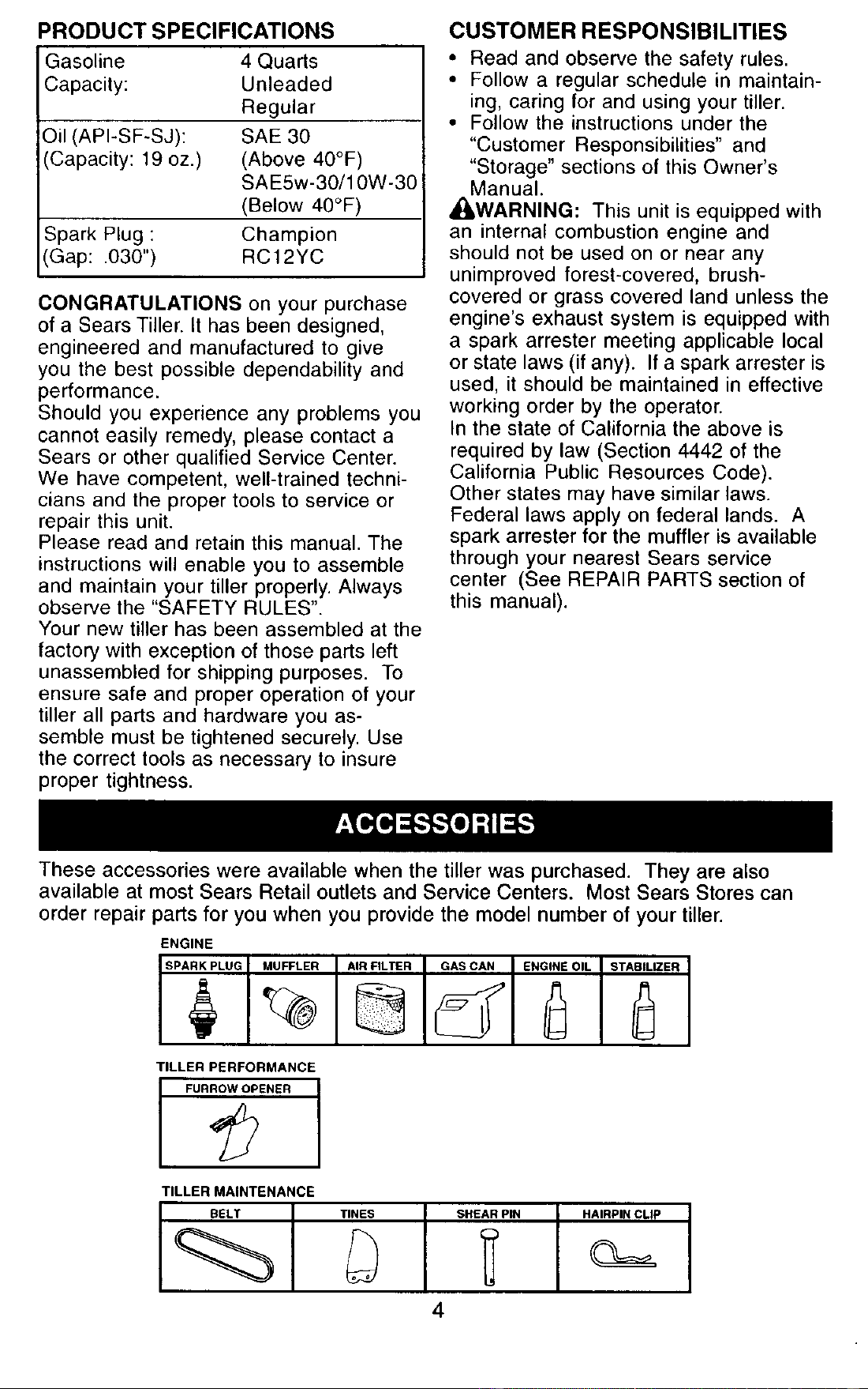
PRODUCT SPECIFICATIONS
Gasoline 4 Quads
Capacity: Unleaded
Regular
Oil (API-SF-SJ): SAE 30
(Capacity: 19 oz.) (Above 40°F)
SAE5w-30/10W-30
(Below 40°F)
Spark Plug : Champion
(Gap: .030") RC12YC
CONGRATULATIONS on your purchase
of a Sears Tiller. It has been designed,
engineered and manufactured to give
you the best possible dependability and
performance.
Should you experience any problems you
cannot easily remedy, please contact a
Sears or other qualified Service Center.
We have competent, well-trained techni-
cians and the proper tools to service or
repair this unit.
Please read and retain this manual. The
instructions will enable you to assemble
and maintain your tiller properly. Always
observe the "SAFETY RULES".
Your new tiller has been assembled at the
factory with exception of those parts left
unassembled for shipping purposes. To
ensure safe and proper operation of your
tiller all parts and hardware you as-
semble must be tightened securely. Use
the correct tools as necessary to insure
proper tightness.
CUSTOMER RESPONSIBILITIES
• Read and observe the safety rules.
• Follow a regular schedule in maintain-
ing, caring for and using your tiller.
• Follow the instructions under the
"Customer Responsibilities" and
"Storage" sections of this Owner's
Manual.
_iLWARNING: This unit is equipped with
an internal combustion engine and
should not be used on or near any
unimproved forest-covered, brush-
covered or grass covered land unless the
engine's exhaust system is equipped with
a spark arrester meeting applicable local
or state laws (if any). If a spark arrester is
used, it should be maintained in effective
working order by the operator.
In the state of California the above is
required by law (Section 4442 of the
California Public Resources Code).
Other states may have similar laws.
Federal laws apply on federal lands. A
spark arrester for the muffler is available
through your nearest Sears service
center (See REPAIR PARTS section of
this manual).
These accessories were available when the tiller was purchased. They are also
available at most Sears Retail outlets and Service Centers. Most Sears Stores can
order repair parts for you when you provide the model number of your tiller.
ENGINE
TILLER PERFORMANCE
FUR_ENER I
TILLER MAINTENANCE
BELT TINES SHEAR PIN HAIRPIN CLIP
4
Your new tiller has been assembled at the
factory with the exception of those parts
left unassembled for shipping purposes.
To ensure safe and proper operation of
your tiller all parts and hardware you
assemble must be tightened securely.
Use the correct tools as necessary to
insure proper tightness.
TOOLS REQUIRED FOR ASSEMBLY
A socket wrench set will make assembly
easier. Standard wrench sizes are listed.
(1) Utility knife
(1) Wire cutter
(1) Tire pressure gauge
(1) Screwdriver
(1) Pair of pliers
(1) 9/16" wrench
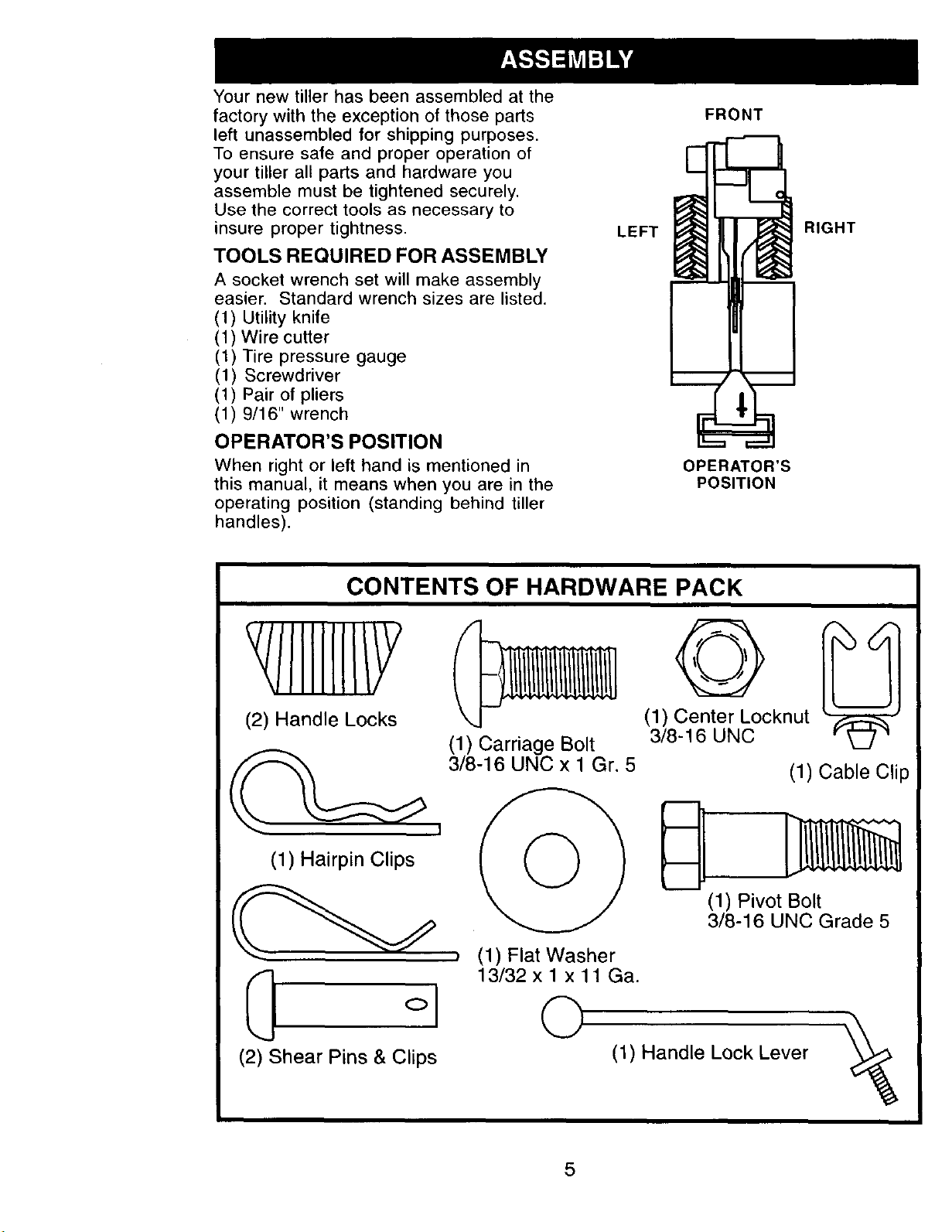
OPERATOR'S POSITION
When right or left hand is mentioned in
this manual, it means when you are in the
operating position (standing behind tiller
handles).
LEFT
FRONT
OPERATOR'S
POSITION
RIGHT
CONTENTS OF HARDWARE PACK
/IIIIIII/Y
(2) Handle Locks
(1) Hairpin Clips
(2) Shear Pins & Clips
(1) Carriage Bolt
3/8-16 UNC x 1 Gr. 5
, (1) Flat Washer
13/32 x 1 x 11 Ga.
©
@
(1) Center Locknut
3/8-16 UNC
(1) Cable Clip
(1) Pivot Bolt
3/8-16 UNC Grade 5
(1) Handle Lock Lever
5
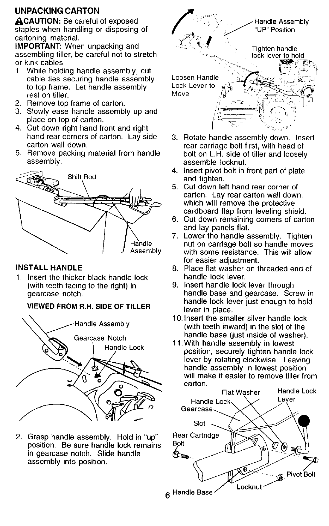
UNPACKING CARTON
_I_CAUTION: Be careful of exposed
staples when handling or disposing of
cartoning material.
IMPORTANT: When unpacking and
assembling tiller, be careful not to stretch
or kink cables.
1. While holding handle assembly, cut
cable ties securing handle assembly
to top frame. Let handle assembly
rest on tiller.
2. Remove top frame of carton.
3. Slowly ease handle assembly up and
place on top of carton.
4. Cut down right hand front and right
hand rear corners of carton. Lay side
carton wall down.
5. Remove packing material from handle
assembly.
Shift Rod
Assembly
INSTALL HANDLE
1. Insert the thicker black handle lock
(with teeth facing to the right) in
gearcase notch.
VIEWED FROM R.H. SIDE OF TILLER
\
Gearcase Notch
Handle Lock
,
3. Rotate handle assembly down. Insert
rear carriage bolt first, with head of
bolt on L.H. side of tiller and loosely
assemble Iocknut.
4. Insert pivot bolt in front part of plate
and tighten.
5. Cut down left hand rear corner of
carton. Lay rear carton wall down,
which will remove the protective
cardboard flap from leveling shield.
6. Cut down remaining corners of carton
and lay panels flat.
7. Lower the handle assembly. Tighten
nut on carriage bolt so handle moves
with some resistance. This will allow
for easier adjustment.
8. Place flat washer on threaded end of
handle lock lever.
9. Insert handle lock lever through
handle base and gearcase. Screw in
handle lock lever just enough to hold
lever in place.
10.Insert the smaller silver handle lock
(with teeth inward) in the slot of the
handle base (just inside of washer).
11 .With handle assembly in lowest
position, securely tighten handle lock
lever by rotating clockwise. Leaving
handle assembly in lowest position
will make it easier to remove tiller from
carton.
Flat Washer Handle Lock
Handle Lock, Lever
\
Slot
Grasp handle assembly. Hold in "up" Rear Cartridge
position. Be sure handle lock remains B/olt
in gearcase notch. Slide handle _
assembly into position.
6 Handle Base
.__ Pivot Bolt
Locknut
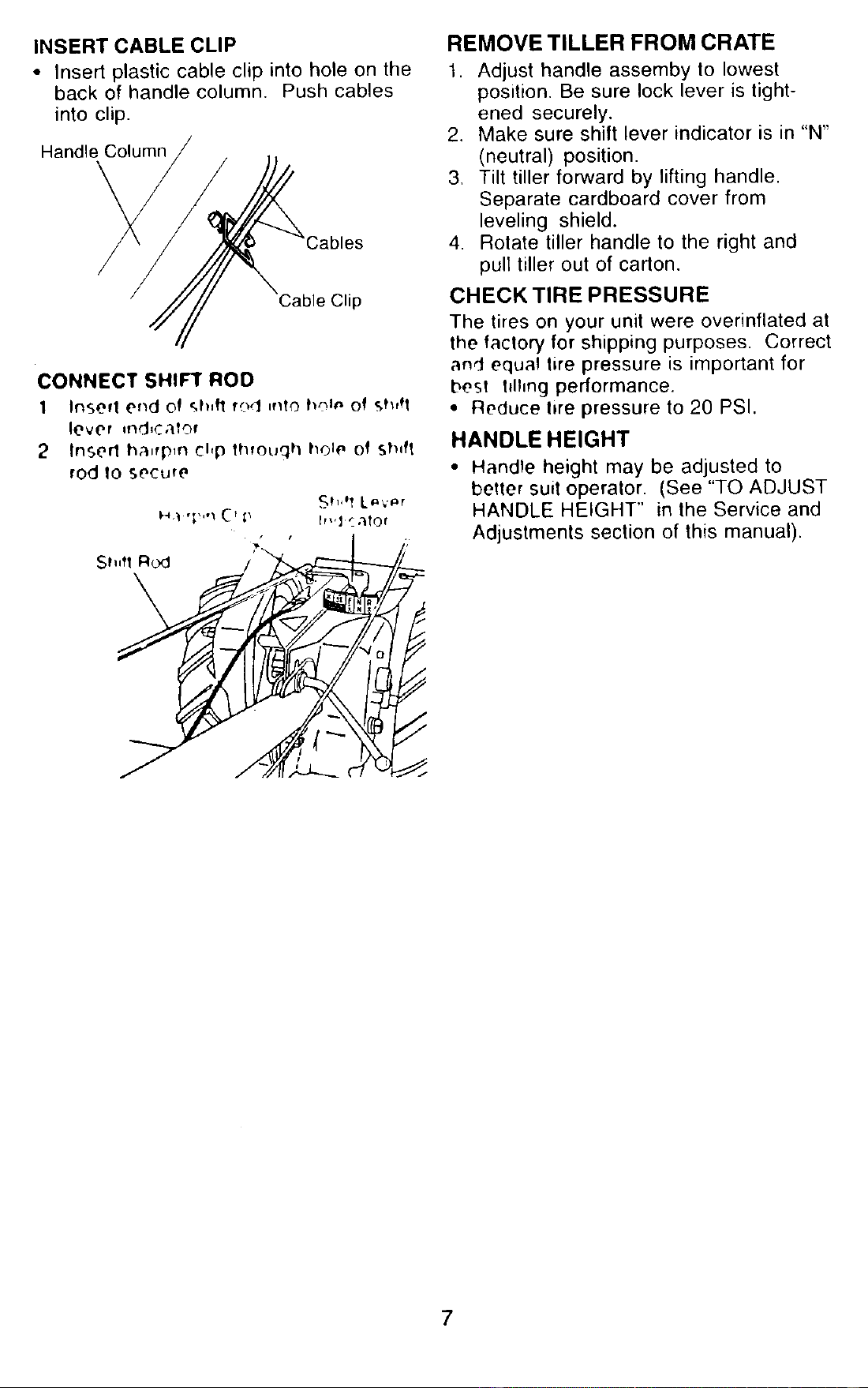
INSERT CABLE CLIP
• Insert plastic cable clip into hole on the
back of handle column, Push cables
into clip.
Handle Column
Cable Clip
CONNECT SHIFT ROD
1 Insert end of _.h,fl rod ,ntO h_l_ of Sh,q
lever rod,cater
2 Insert ha,fp_n chp lhtouqh hOIe Of shift
rod |0 Secure
I_ ,1_,,,_CT p h_,] ".'ltOf
REMOVE TILLER FROM CRATE
1. Adjust handle assemby to lowest
position. Be sure lock lever is tight-
ened securely.
2, Make sure shift lever indicator is in "N"
(neutral) position.
3, Tilt tiller forward by lifting handle.
Separate cardboard cover from
leveling shield.
4. Rotate tiller handle to the right and
pull tiller out of carton.
CHECK TIRE PRESSURE
The tires on your unit were overinflated at
the factory for shipping purposes. Correct
and equal tire pressure is important for
best hllmg performance.
• Reduce hre pressure to 20 PSI.
HANDLE HEIGHT
• Handle height may be adjusted to
better suit operator. (See "TO ADJUST
HANDLE HEIGHT" in the Service and
Adjustments section of this manual).
7
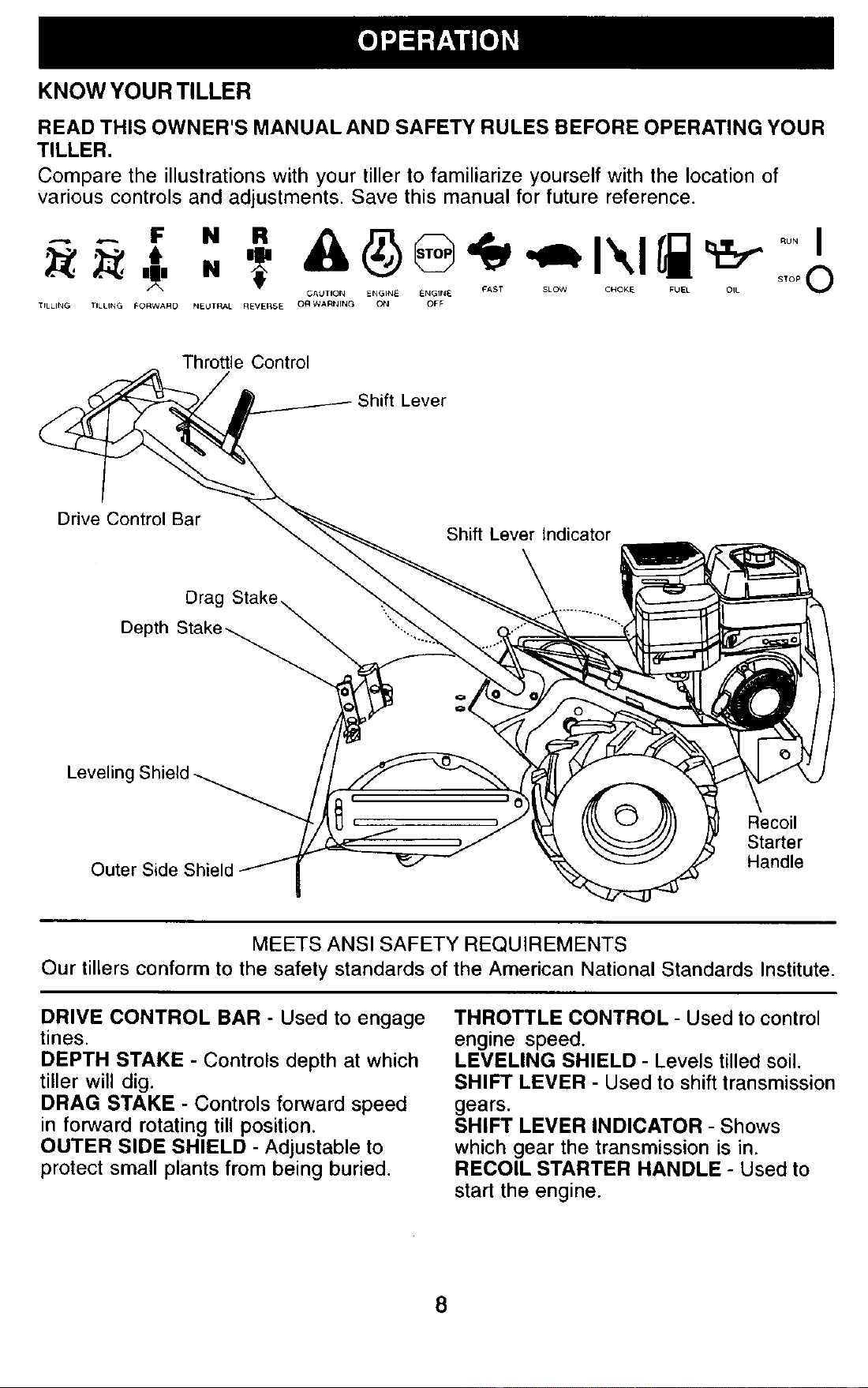
KNOW YOUR TILLER
READ THIS OWNER'S MANUAL AND SAFETY RULES BEFORE OPERATING YOUR
TILLER.
Compare the illustrations with your tiller to familiarize yourself with the location of
various controls and adjustments. Save this manual for future reference.
. s,o.
CAUTION ENGINE ENGINE CAST SLOW CHOKE FUEL OIL
TILLING TILLING FORWARD NEUTRAL REVERSE O_ WARNING ON OFF
Throttle Control
;hift Lever
Drive Control Bar
Shift Lever Indicator
Drag
Depth
Leveling Shield
Outer Side Shield
Q
, Recoil
Starter
Handle
MEETS ANSI SAFETY REQUIREMENTS
Our tillers conform to the safety standards of the American National Standards Institute.
DRIVE CONTROL BAR - Used to engage
tines.
DEPTH STAKE - Controls depth at which
tiller will dig.
DRAG STAKE - Controls forward speed
in forward rotating till position.
OUTER SIDE SHIELD - Adjustable to
protect small plants from being buried.
THROTTLE CONTROL - Used to control
engine speed.
LEVELING SHIELD - Levels tilled soil.
SHIFT LEVER - Used to shift transmission
gears.
SHIFT LEVER INDICATOR - Shows
which gear the transmission is in.
RECOIL STARTER HANDLE - Used to
start the engine.
8
The operation of any tiller can result in foreign objects thrown into the eyes,
which can result in severe eye damage. Always wear safety glasses or eye
shields before starting your tiller and while tilling. We recommend standard
safety glasses or a wide vision safety mask worn over spectacles.
HOW TO USE YOUR TILLER
Know how to operate all controls before
adding fuel and oil or attempting to start
engine.
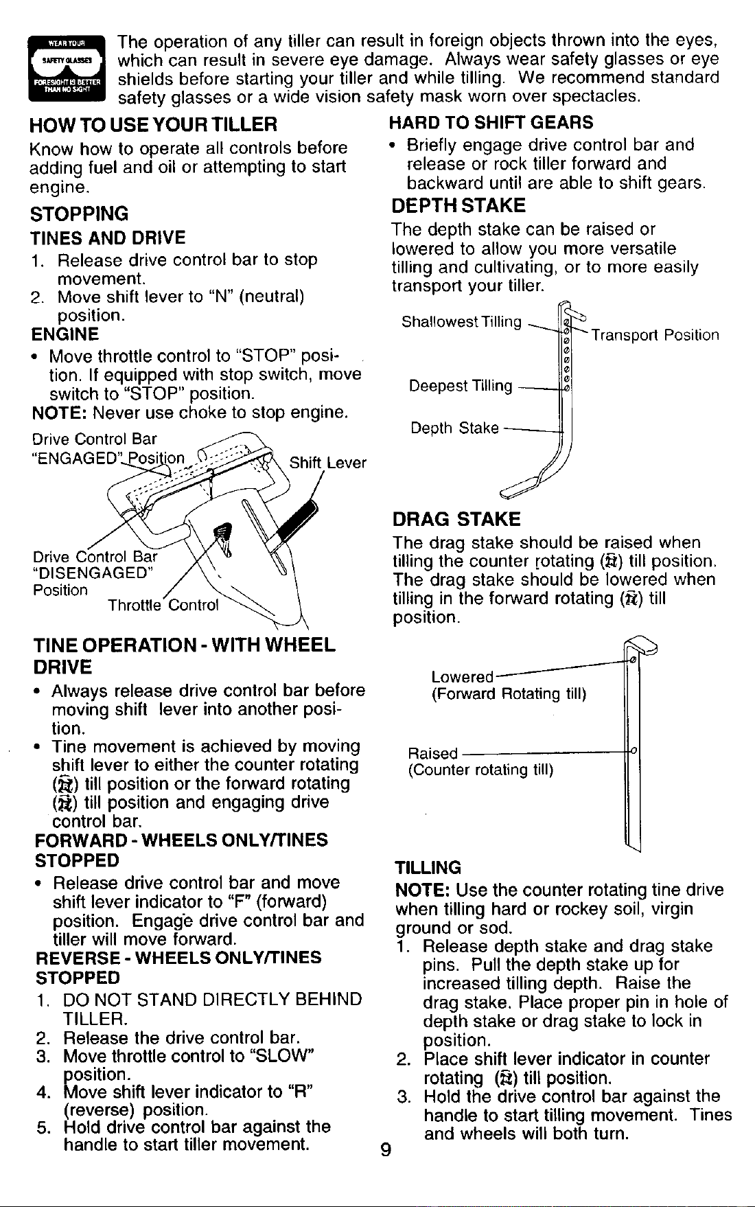
STOPPING
TINES AND DRIVE
1. Release drive control bar to stop
movement.
2. Move shift lever to "N" (neutral)
position.
ENGINE
• Move throttle control to "STOP" posi-
tion. If equipped with stop switch, move
switch to "STOP" position.
NOTE: Never use choke to stop engine.
Drive Control Bar
"ENGAGED'
Shift Lever
HARD TO SHIFT GEARS
• Briefly engage drive control bar and
release or rock tiller forward and
backward until are able to shift gears.
DEPTH STAKE
The depth stake can be raised or
lowered to allow you more versatile
tilling and cultivating, or to more easily
transport your tiller.
Shallowest Tilling
Deepest Tilling
Depth Stake
_'Transport Position
J
DRAG STAKE
Drive Control Bar
"DISENGAGED"
Position
The drag stake should be raised when
tilling the counter rotating (_) till position.
The drag stake should be lowered when
tilling in the forward rotating (_;) till
position.
TINE OPERATION - WITH WHEEL
DRIVE
• Always release drive control bar before
moving shift lever into another posi-
tion.
• Tine movement is achieved by moving
shift lever to either the counter rotating
(_,) till position or the forward rotating
(_) till position and engaging drive
control bar.
FORWARD - WHEELS ONLY/TINES
STOPPED
• Release drive control bar and move
shift lever indicator to "F" (forward)
position. Engage drive control bar and
tiller will move forward.
REVERSE - WHEELS ONLY/TINES
STOPPED
1. DO NOT STAND DIRECTLY BEHIND
TILLER.
2. Release the drive control bar.
3. Move throttle control to "SLOW"
position.
4. Move shift lever indicator to "R"
(reverse) position.
5. Hold drive control bar against the
handle to start tiller movement.
J
Lowered _
(Forward Rotating till)
Raised
(Counter rotating till)
9
TILLING
NOTE: Use the counter rotating tine drive
when tilling hard or rockey soil, virgin
ground or sod.
1. Release depth stake and drag stake
pins. Pull the depth stake up for
increased tilling depth. Raise the
drag stake, Place proper pin in hole of
depth stake or drag stake to lock in
position.
2. Place shift lever indicator in counter
rotating (_) till position.
3. Hold the drive control bar against the
handle to start tilling movement. Tines
and wheels will both turn.
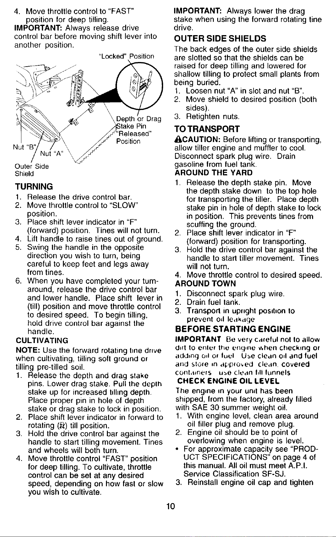
4. Move throttle control to "FAST"
position for deep tilling.
IMPORTANT: Always release drive
control bar before moving shift lever into
another position.
"Locked" Position
Depth )r Drag
Nut
Position
Outer Side
Shield
TURNING
1. Release the drive control bar.
2. Move throttle control to "SLOW"
position.
3. Place shift lever indicator in "F"
(forward) position. Tines will not turn.
4. Lift handle to raise tines out of ground.
5. Swing the handle in the opposite
direction you wish to turn, being
careful to keep feet and legs away
from tines.
6. When you have completed your turn-
around, release the drive control bar
and lower handle. Place shift lever in
(till) position and move throttle control
to desired speed. To begin tilling.
hold drive control bar against the
handle.
CULTIVATING
NOTE: Use the forward rotating tree dnve
when cultivating, tilling soft ground or
tilling pre-tilled soil.
1. Release the depth and drag slake
pins. Lower drag stake. Pull the deplh
stake up for increased tilling depth.
Place proper pin in hole of depth
stake or drag stake to lock in position.
2. Place shift lever indicator in forward to
rotating (_:) till position.
3. Hold the drive control bar against the
handle to start tilling movement. Tines
and wheels will both turn.
4. Move throttle control "FAST" position
for deep tilling. To cultivate, throttle
control can be set at any desired
speed, depending on how fast or slow
you wish to cultivate.
IMPORTANT: Always lower the drag
stake when using the forward rotating tine
drive.
OUTER SIDE SHIELDS
The back edges of the outer side shields
are slotted so that the shields can be
raised for deep tilling and lowered for
shallow tilling to protect small plants from
being buried.
1. Loosen nut "A" in slot and nut "B".
2. Move shield to desired position (both
sides).
3. Retighten nuts.
TO TRANSPORT
_i,CAUTION: Before lifting or transporting,
allow tiller engine and muffler to cool.
Disconnect spark plug wire. Drain
gasoline from fuel tank.
AROUND THE YARD
1. Release the depth stake pin. Move
the depth stake down to the top hole
for transporting the tiller. Place depth
stake pin in hole of depth stake to lock
in position. This prevents tines from
scuffing the ground.
2. Place shift lever indicator in "F"
(forward) position for transporting.
3. Hold the drive control bar against the
handle to start tiller movement. Tines
will not turn.
4. Move throttle control to desired speed.
AROUND TOWN
1. Disconnect spark plug wire.
2. Drain fuel tank.
3. Transport in upright posd_on to
prevent od leakage
BEFORE STARTING ENGINE
IMPORTANT Be very careful not to allow
d_rt Io enler the en(]_ne _,hen checkang or
adding oil or tuel U_e clean ed and fuel
and store _n a_pfoved cledn, covered
cor_l,l_ners u_e clean hll funnels
CHECK ENGINE OIL LEVEL
The engine in your unal has been
shipped, from the factory, already filled
with SAE 30 summer weight oil.
1. With engine level, clean area around
oil filler plug and remove plug.
2. Engine oil should be to point of
overlowing when engine is level.
• For approximate capacity see "PROD-
UCT SPECIFICATIONS" on page 4 of
this manual. All oil must meet A.P.I.
Service Classification SF-SJ.
3. Reinstall engine oil cap and tighten
10
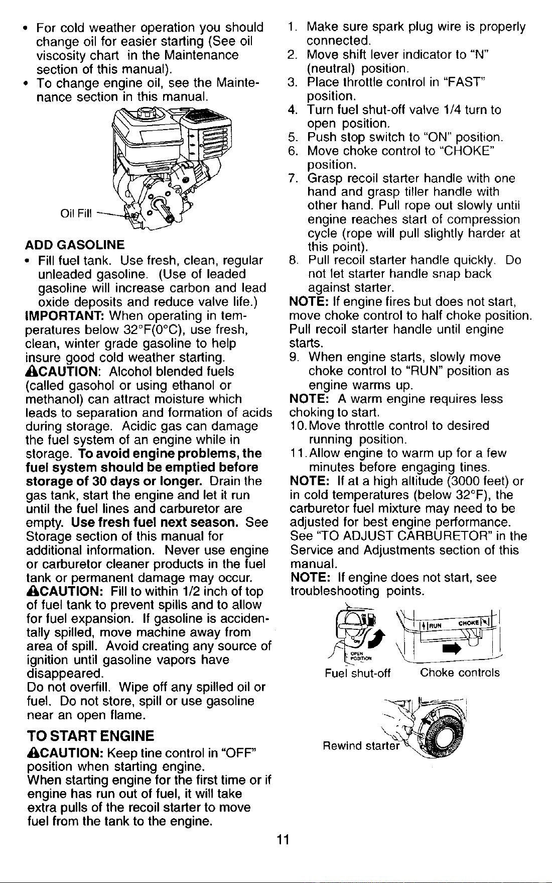
• For cold weather operation you should
change oil for easier starting (See oil
viscosity chart in the Maintenance
section of this manual).
• To change engine oil, see the Mainte-
nance section in this manual.
Oil Fill _ _o_,
ADD GASOLINE
• Fill fuel tank. Use fresh, clean, regular
unleaded gasoline. (Use of leaded
gasoline will increase carbon and lead
oxide deposits and reduce valve life.)
IMPORTANT: When operating in tem-
peratures below 32°F(0°C), use fresh,
clean, winter grade gasoline to help
insure good cold weather starting.
_I:_CAUTION: Alcohol blended fuels
(called gasohol or using ethanol or
methanol) can attract moisture which
leads to separation and formation of acids
during storage. Acidic gas can damage
the fuel system of an engine while in
storage. To avoid engine problems, the
fuel system should be emptied before
storage of 30 days or longer. Drain the
gas tank, start the engine and let it run
until the fuel lines and carburetor are
empty. Use fresh fuel next season. See
Storage section of this manual for
additional information. Never use engine
or carburetor cleaner products in the fuel
tank or permanent damage may occur.
_I_CAUTION: Fill to within 1/2 inch of top
of fuel tank to prevent spills and to allow
for fuel expansion. If gasoline is acciden-
tally spilled, move machine away from
area of spill. Avoid creating any source of
ignition until gasoline vapors have
disappeared.
Do not overfill. Wipe off any spilled oil or
fuel. Do not store, spill or use gasoline
near an open flame.
TO START ENGINE
A, CAUTION: Keep tine control in "OFF"
position when starting engine.
When starting engine for the first time or if
engine has run out of fuel, it will take
extra pulls of the recoil starter to move
fuel from the tank to the engine.
1. Make sure spark plug wire is properly
connected.
2. Move shift lever indicator to "N"
(neutral) position.
3. Place throttle control in "FAST"
position.
4. Turn fuel shut-off valve 1/4 turn to
open position.
5. Push stop switch to "ON" position.
6. Move choke control to "CHOKE"
position.
7. Grasp recoil starter handle with one
hand and grasp tiller handle with
other hand. Pull rope out slowly until
engine reaches start of compression
cycle (rope will pull slightly harder at
this point).
8. Pull recoil starter handle quickly. Do
not let starter handle snap back
against starter.
NOTE: If engine fires but does not start,
move choke control to half choke position.
Pull recoil starter handle until engine
starts.
9. When engine starts, slowly move
choke control to "RUN" position as
engine warms up.
NOTE: A warm engine requires less
choking to start.
10. Move throttle control to desired
running position.
11 .Allow engine to warm up for a few
minutes before engaging tines.
NOTE: If at a high altitude (3000 feet) or
in cold temperatures (below 32°F), the
carburetor fuel mixture may need to be
adjusted for best engine performance.
See "TO ADJUST CARBURETOR" in the
Service and Adjustments section of this
manual.
NOTE: If engine does not start, see
troubleshooting points.
Fuel shut-off Choke controls
11
Rewind starter _
TILLING HINTS
_aaCAUTION: Until you are accustomed to
ndling your tiller, start actual field use
with throttle in slow position (mid-way
between "FAST" and "IDLE").
• Tilling is digging into, turning over, and
breaking up packed soil before
planting. Loose, unpacked soil helps
root growth. Best tilling depth is 4" to 6".
A tiller will also clear the soil of un-
wanted vegetation. The decomposition
of this vegetable matter enriches the
soil. Depending on the climate (rainfall
and wind), it may be advisable to till the
soil at the end of the growing season to
further condition the soil.
• Soil conditions are important for proper
tilling. Tines will not readily penetrate
dry, hard soil which may contribute to
excessive bounce and difficult handling
of your tiller. Hard soil should be
moistened before tilling; however,
extremely wet soil will "ball-up" or
clump during tilling. Wait until the soil is
less wet in order to achieve the best
results. When tilling in the fall, remove
vines and long grass to prevent them
from wrapping around the tine shaft
and slowing your tilling operation.
• You will find tilling much easier if you
leave a row untilled between passes.
Then go back between tilled
rows.There are two reasons for doing
this. First, wide turns are much easier to
negotiate than about-faces. Second,
the tiller won't be pulling itself, and
you, toward the row next to it.
• Do not lean on handle. This takes
weight off the wheels and reduces
traction. To get through a really tough
section of sod or hard ground, apply
upward pressure on handle or lower
the depth stake.
CULTIVATING
Cultivating is destroying the weeds
between rows to prevent them from
robbing nourishment and moisture from
the plants. At the same time, breaking up
the upper layer of soil crust will help
retain moisture in the soil. Best digging
depth is 1" to 3" (2.5-7.5 cm). Lower the
outer side shields to protect small plants
from being buried.
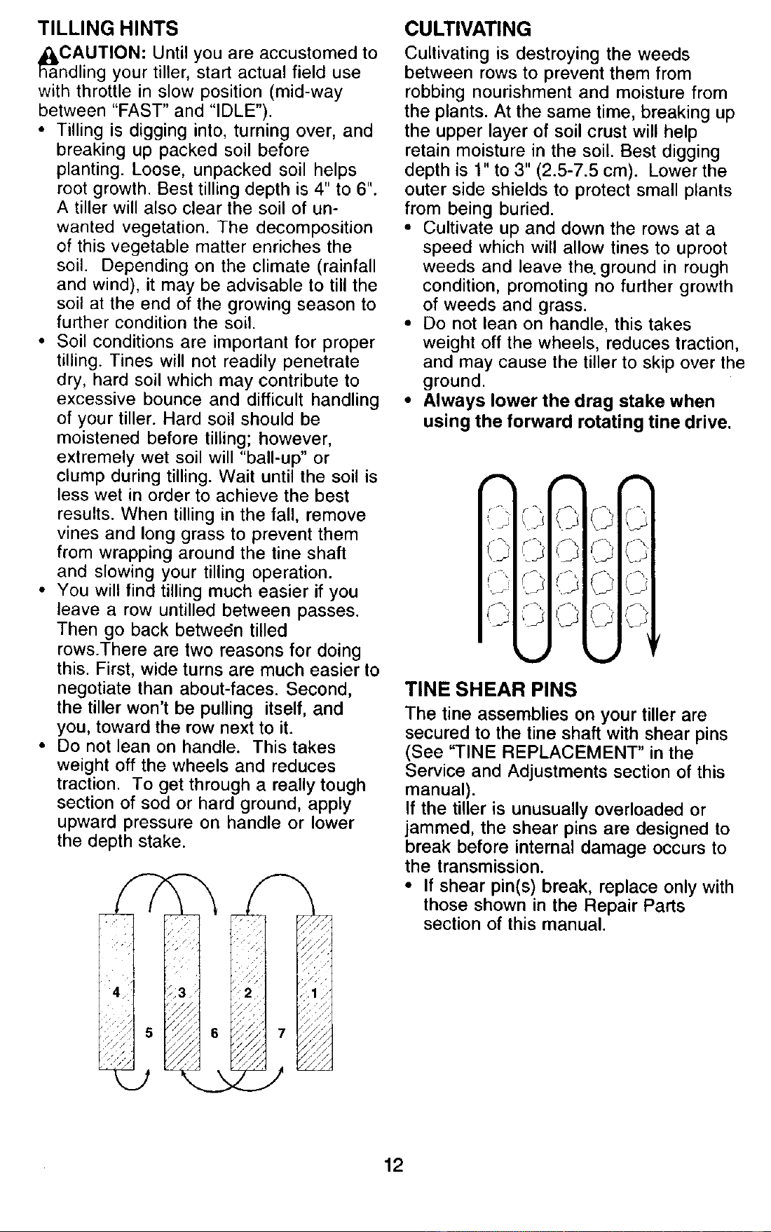
• Cultivate up and down the rows at a
speed which will allow tines to uproot
weeds and leave the. ground in rough
condition, promoting no further growth
of weeds and grass.
• Do not lean on handle, this takes
weight off the wheels, reduces traction,
and may cause the tiller to skip over the
ground.
• Always lower the drag stake when
using the forward rotating tine drive.
,,=% _
I
_, ,,J
TINE SHEAR PINS
The tine assemblies on your tiller are
secured to the tine shaft with shear pins
(See "TINE REPLACEMENT" in the
Service and Adjustments section of this
manual).
If the tiller is unusually overloaded or
jammed, the shear pins are designed to
break before internal damage occurs to
the transmission.
• If shear pin(s) break, replace only with
those shown in the Repair Parts
section of this manual.
12
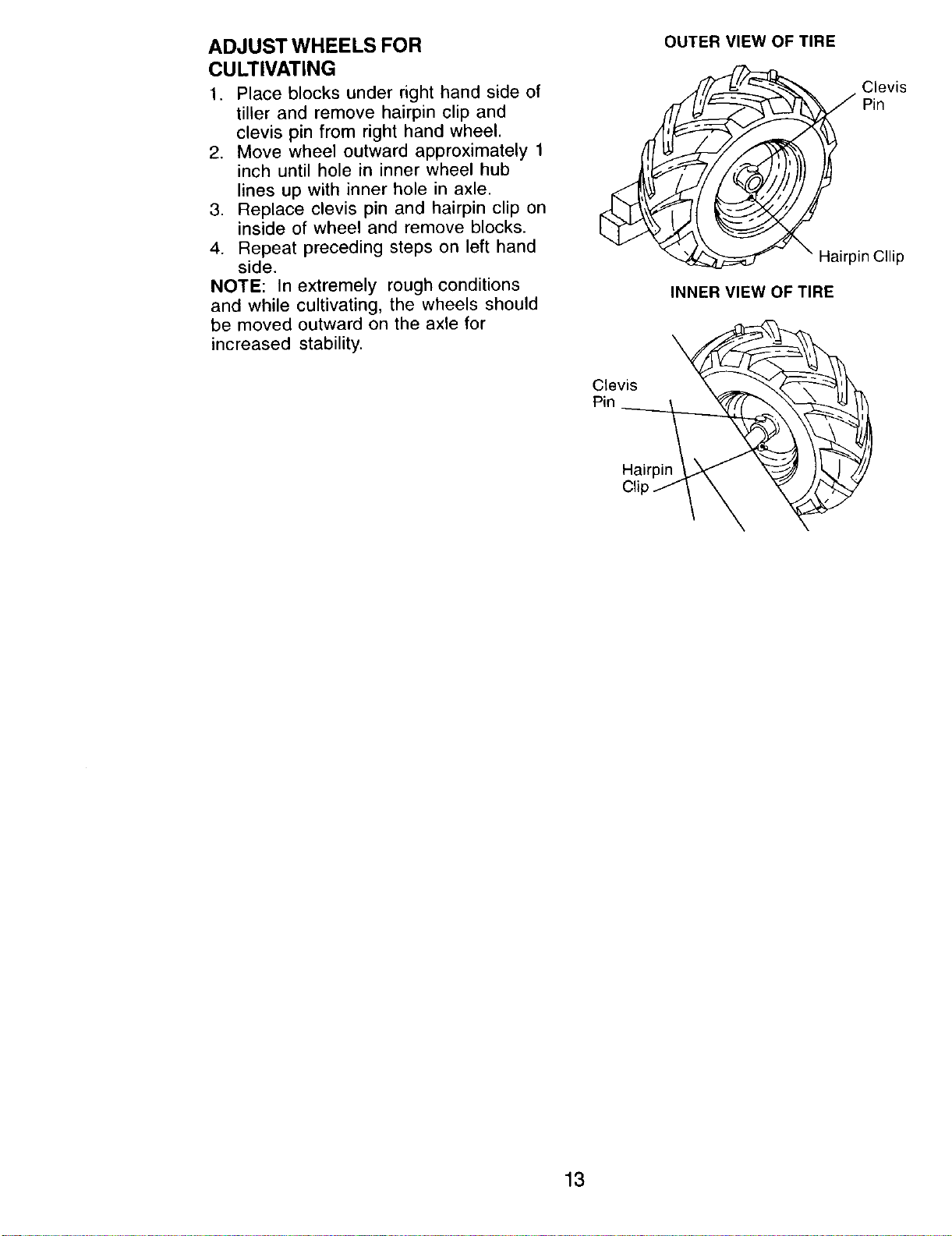
ADJUST WHEELS FOR
CULTIVATING
1. Place blocks under right hand side of
tiller and remove hairpin clip and
clevis pin from right hand wheel.
2. Move wheel outward approximately 1
inch until hole in inner wheel hub
lines up with inner hole in axle.
3. Replace clevis pin and hairpin clip on
inside of wheel and remove blocks.
4. Repeat preceding steps on left hand
side.
NOTE: In extremely rough conditions
and while cultivating, the wheels should
be moved outward on the axle for
increased stability.
Clevis
Pin
OUTER VIEW OF TIRE
Clevis
Pin
Hairpin Cllip
INNER VIEW OF TIRE
Hairpin
13
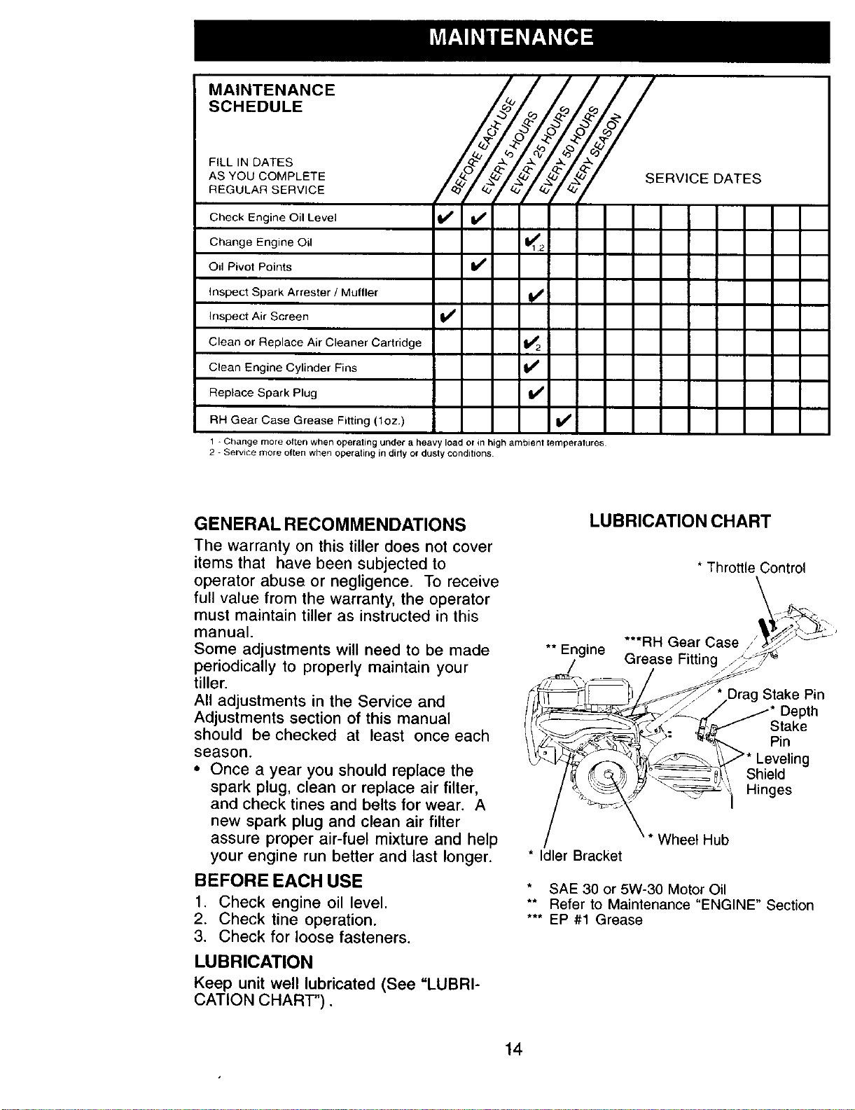
MAINTENANCE
SCHEDULE
FILL IN DATES
AS YOU COMPLETE
REGULAR SERVICE
I°+I+/+Y+Y+7
Check Engine Oil Level If V'
Change Engine Oil I_12
Oil Pivot Points I_
+I
v'
v'
v'
v'
SERVICE DATES
inspect Spark Arrester / Muffler
Inspect Air Screen
Clean or Replace Air Cleaner Cartridge
Clean Engine Cylinder Fins
Replace Spark Plug
RH Gear Case Grease Fitting (1oz.)
1+Change more often when operating under a heavy load orin high ambient temperatures
2 - Service more oftenwhen operating in dirty or dusty conditions
GENERAL RECOMMENDATIONS
The warranty on this tiller does not cover
items that have been subjected to
operator abuse or negligence. To receive
full value from the warranty, the operator
must maintain tiller as instructed in this
manual.
Some adjustments will need to be made
periodically to properly maintain your
tiller.
All adjustments in the Service and
Adjustments section of this manual
should be checked at least once each
season.
• Once a year you should replace the
spark plug, clean or replace air filter,
and check tines and belts for wear. A
new spark plug and clean air filter
assure proper air-fuel mixture and help
your engine run better and last longer.
BEFORE EACH USE
1. Check engine oil level.
2. Check tine operation.
3. Check for loose fasteners.
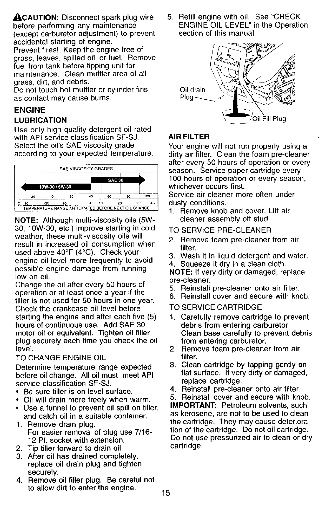
LUBRICATION
Keep unit well lubricated (See "LUBRI-
CATION CHART").
LUBRICATION CHART
* Throttle Control
** Engine
***RH Gear Case/_
Grease Fitting J-
Stake Pin
Depth
Stake
Pin
Shield
Hinges
* Idler Bracket
Wheet Hub
SAE 30 or 5W-30 Motor Oil
** Refer to Maintenance "ENGINE" Section
*** EP #1 Grease
14
_kCAUTION: Disconnect spark plug wire
before performing any maintenance
(except carburetor adjustment) to prevent
accidental starting of engine.
Prevent fires! Keep the engine free of
grass, leaves, spilled oil, or fuel. Remove
fuel from tank before tipping unit for
maintenance. Clean muffler area of all
grass, dirt, and debris.
Do not touch hot muffler or cylinder fins
as contact may cause burns.
ENGINE
LUBRICATION
Use only high quality detergent oil rated
with API service classification SF-SJ.
Select the oil's SAE viscosity grade
according to your expected temperature.
SAE VISCOSITY GRADES
20 30 40
C .30 20 10 4 10 20 30
TEMPERATURE RANG_E ANTICIPATED BEFORE N_T OIL C_A'N GE
NOTE: Although multi-viscosity oils (5W-
30, 10W-30, etc.) improve starting in cold
weather, these multi-viscosity oils will
result in increased oil consumption when
used above 40°F (4°C). Check your
engine oil level more frequently to avoid
possible engine damage from running
low on oil.
Change the oil after every 50 hours of
operation or at least once a year if the
tiller is not used for 50 hours in one year.
Check the crankcase oil level before
starting the engine and after each five (5)
hours of continuous use. Add SAE 30
motor oil or equivalent. Tighten oil filler
plug securely each time you check the oil
level.
TO CHANGE ENGINE OIL
Determine temperature range expected
before oil change. All oil must meet API
service classification SF-SJ.
• Be sure tiller is on level surface.
• Oil will drain more freely when warm.
• Use a funnel to prevent oil spill on tiller,
and catch oil in a suitable container.
1. Remove drain plug.
For easier removal of plug use 7/16-
12 Pt. socket with extension.
2. Tip tiller forward to drain oil.
3. After oil has drained completely,
replace oil drain plug and tighten
securely.
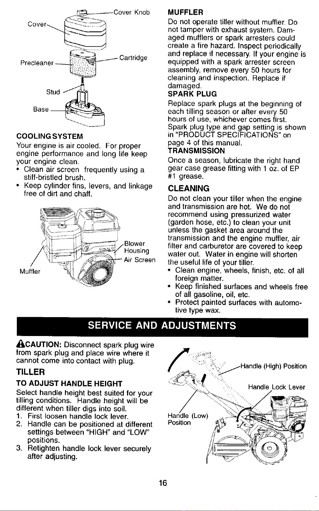
4. Remove oil filler plug. Be careful not
to allow dirt to enter the engine.
5. Refill engine with oil. See "CHECK
ENGINE OIL LEVEL" in the Operation
section of this manual.
\ / Oil Fill Plug
AIR FILTER
Your engine will not run properly using a
dirty air filter. Clean the foam pre-cleaner
after every 50 hours of operation or every
season. Service paper cartridge every
100 hours of operation or every season,
whichever occurs first.
Service air cleaner more often under
dusty conditions.
1. Remove knob and cover. Lift air
cleaner assembly off stud.
TO SERVICE PRE-CLEANER
2. Remove foam pre-cleaner from air
filter.
3. Wash it in liquid detergent and water.
4. Squeeze it dry in a clean cloth.
NOTE: If very dirty or damaged, replace
pre-cleaner.
5. Reinstall pre-cleaner onto air filter.
6. Reinstall cover and secure with knob.
TO SERVICE CARTRIDGE
1. Carefully remove cartridge to prevent
debris from entering carburetor.
Clean base carefully to prevent debris
from entering carburetor.
2. Remove foam pre-cleaner from air
filter.
3. Clean cartridge by tapping gently on
flat surface. If very dirty or damaged,
replace cartridge.
4. Reinstall pre-cleaner onto air filter.
5. Reinstall cover and secure with knob.
IMPORTANT: Petroleum solvents, such
as kerosene, are not to be used to clean
the cartridge. They may cause deteriora-
tion of the cartridge. Do not oil cartridge.
Do not use pressurized air to clean or dry
cartridge.
15
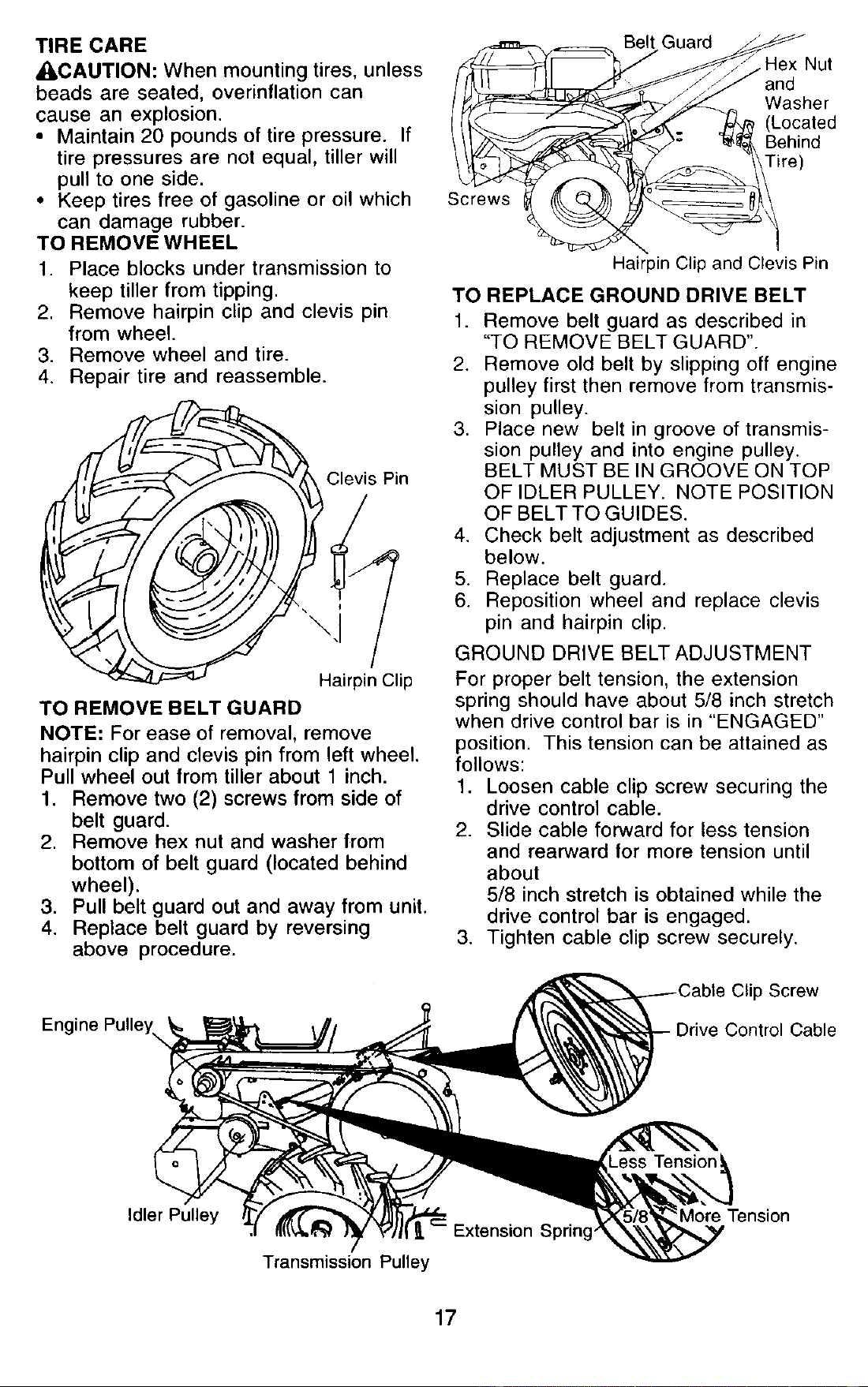
_----_ Cover Knob
Cover
Precleaner_... _I Cartridge
Bas:tUd "_i _
COOLING SYSTEM
Your engine is air cooled. For proper
engine performance and long life keep
your engine clean.
• Clean air screen frequently using a
stiff-bristled brush.
• Keep cylinder fins, levers, and linkage
free of dirt and chaff.
Muffler
Screen
MUFFLER
Do not operate tiller without muffler. Do
not tamper with exhaust system. Dam-
aged mufflers or spark arresters could
create a fire hazard. Inspect periodically
and replace if necessary. If your engine is
equipped with a spark arrester screen
assembly, remove every 50 hours for
cleaning and inspection. Replace if
damaged.
SPARK PLUG
Replace spark plugs at the beginning of
each tilling season or after every 50
hours of use, whichever comes first.
Spark plug type and gap setting is shown
in "PRODUCT SPECIFICATIONS" on
page 4 of this manual.
TRANSMISSION
Once a season, lubricate the right hand
gear case grease fitting with 1 oz. of EP
#1 grease.
CLEANING
Do not clean your tiller when the engine
and transmission are hot. We do not
recommend using pressurized water
(garden hose, etc.) to clean your unit
unless the gasket area around the
transmission and the engine muffler, air
filter and carburetor are covered to keep
water out. Water in engine will shorten
the useful life of your tiller.
• Clean engine, wheels, finish, etc. of all
foreign matter.
• Keep finished surfaces and wheels free
of all gasoline, oil, etc.
• Protect painted surfaces with automo-
tive type wax.
J_.CAUTION: Disconnect spark plug wire
from spark plug and place wire where it
cannot come into contact with plug.
TILLER
TO ADJUST HANDLE HEIGHT
Select handle height best suited for your
tilling conditions. Handle height will be
different when tiller digs into soil.
1. First loosen handle lock lever.
2. Handle can be positioned at different
settings between "HIGH" and "LOW"
positions.
3. Retighten handle lock lever securely
after adjusting.
Position
(High) Position
, Handle Lock Lever
16
TIRE CARE
ACAUTION: When mounting tires, unless
beads are seated, overinflation can
cause an explosion.
• Maintain 20 pounds of tire pressure. If
tire pressures are not equal, tiller will
pull to one side.
• Keep tires free of gasoline or oil which
can damage rubber.
TO REMOVE WHEEL
1. Place blocks under transmission to
keep tiller from tipping•
2. Remove hairpin clip and clevis pin
from wheel.
3. Remove wheel and tire.
4. Repair tire and reassemble.
Clevis Pin
TO REMOVE BELT GUARD
NOTE: For ease of removal, remove
hairpin clip and clevis pin from left wheel.
Pull wheel out from tiller about 1 inch.
1. Remove two (2) screws from side of
belt guard.
2. Remove hex nut and washer from
bottom of belt guard (located behind
wheel).
3. Pull belt guard out and away from unit.
4. Replace belt guard by reversing
above procedure.
Engine Pulley,,,
Screws
Belt Guard
•Hex Nut
and
Washer
(Located
Behind
Tire)
Hairpin Clip and Clevis Pin
TO REPLACE GROUND DRIVE BELT
1. Remove belt guard as described in
"TO REMOVE BELT GUARD".
2. Remove old belt by slipping off engine
pulley first then remove from transmis-
sion pulley.
3. Place new belt in groove of transmis-
sion pulley and into engine pulley.
BELT MUST BE IN GROOVE ON TOP
OF IDLER PULLEY. NOTE POSITION
OF BELT TO GUIDES.
4. Check belt adjustment as described
below.
5. Replace belt guard.
6. Reposition wheel and replace clevis
pin and hairpin clip.
GROUND DRIVE BELT ADJUSTMENT
For proper belt tension, the extension
spring should have about 5/8 inch stretch
when drive control bar is in "ENGAGED"
position. This tension can be attained as
follows:
1. Loosen cable clip screw securing the
drive control cable.
2. Slide cable forward for less tension
and rearward for more tension until
about
5/8 inch stretch is obtained while the
drive control bar is engaged.
3. Tighten cable clip screw securely.
p Screw
Control Cable
Idler Pulley
Extension Spring,
Transmission Pulley
More Tension
17
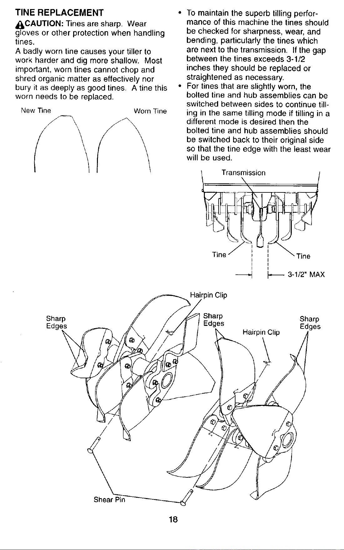
TINEREPLACEMENT
_II,CAUTION: Tines are sharp. Wear
gloves or other protection when handling
tines.
A badly worn tine causes your tiller to
work harder and dig more shallow. Most
important, worn tines cannot chop and
shred organic matter as effectively nor
bury it as deeply as good tines. A tine this
worn needs to be replaced.
New Tine Worn Tine
• To maintain the superb tilling perfor-
mance of this machine the tines should
be checked for sharpness, wear, and
bending, particularly the tines which
are next to the transmission. If the gap
between the tines exceeds 3-1/2
inches they should be replaced or
straightened as necessary.
• For tines that are slightly worn, the
bolted tine and hub assemblies can be
switched between sides to continue till-
ing in the same tilling mode if tilling in a
different mode is desired then the
bolted tine and hub assemblies should
be switched back to their original side
so that the tine edge with the least wear
will be used.
_Trans_ission
I I
I I
3-1/2" MAX
Clip
Sharp
Edgl
Sharp Sharp
Edges Edges
Hairpin Clip
/
18
ENGINE
Maintenance, repair, or replacement of
the emission control devices and sys-
tems, which are being done at the
customers expense, may be performed
by any non-road engine repair establish-
ment or individual. Warranty repairs must
be performed by an authorized engine
manufacturer's service outlet.
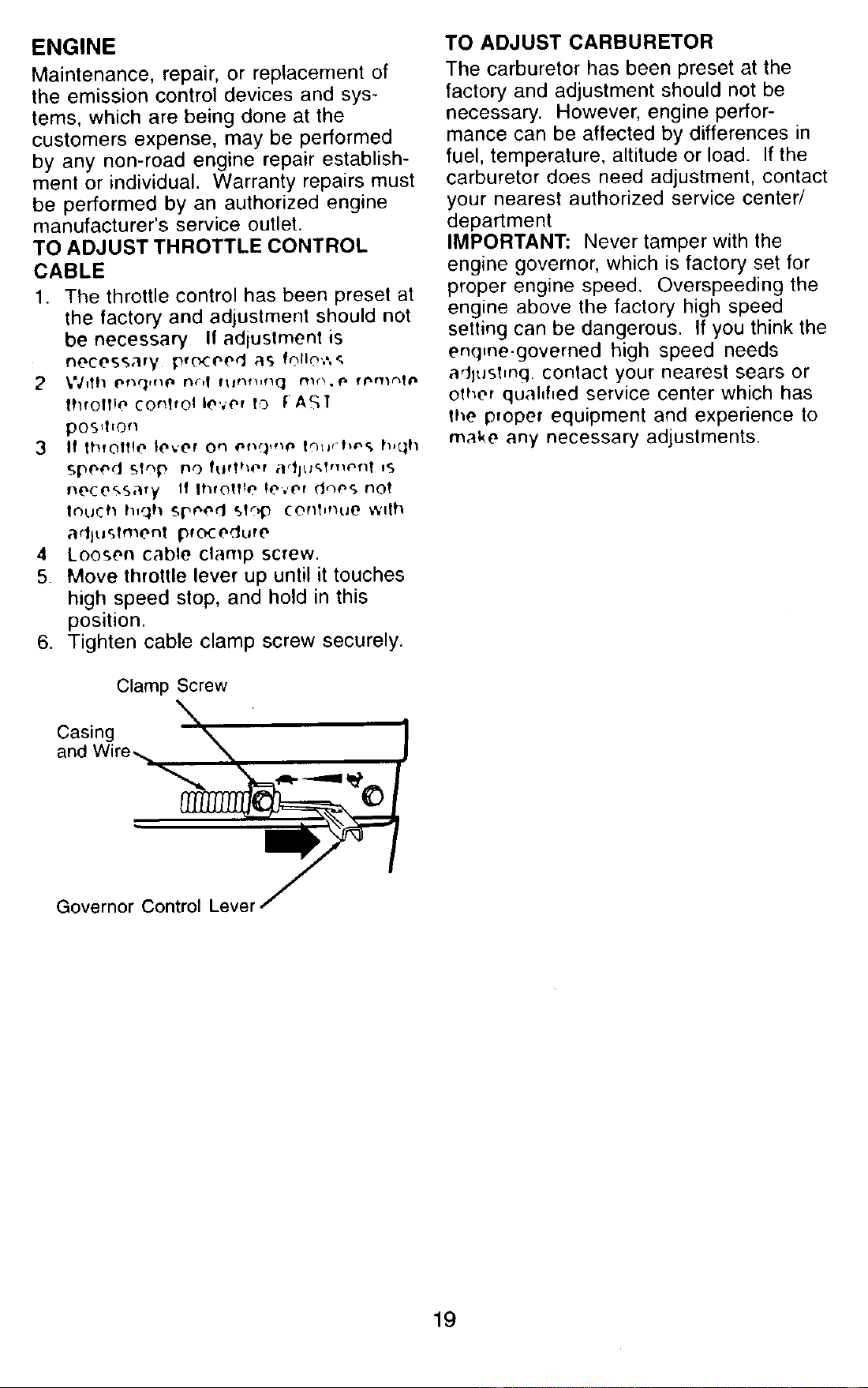
TO ADJUST THROTTLE CONTROL
CABLE
1. The throttle control has been preset at
the factory and adjustment should not
be necessary If adiustment is
necessary iPro_eed as folio',',',
lhrolflo COnTrolle'¢er IO fAST
pos_Tvorl
3 If throttle level on #r_,:l,,_' lfl;Ir'h¢'_* h,(lh
Sp("e(J Sf'f, nO ftlflher ar_JUkTt*l_l'_f'll IS
necessary If throttle le',,Pf dqo(_ nol
Ic)uCh h_qh Si_¢'e,'I STop cenT,hue wilh
adlu£Tmenl pfc_edure
4 Loosen cable clamp screw.
5. Move lhrottle lever up until it touches
high speed stop, and hold in this
position.
6. Tighten cable clamp screw securely.
Clamp Screw
Cnac_i_re "% X% •
Governor' Cont__rol_
TO ADJUST CARBURETOR
The carburetor has been preset at the
factory and adjustment should not be
necessary. However, engine perfor-
mance can be affected by differences in
fuel, temperature, altitude or load. If the
carburetor does need adjustment, contact
your nearest authorized service center/
department
IMPORTANT: Never tamper with the
engine governor, which is factory set for
proper engine speed. Overspeeding the
engine above the factory high speed
setting can be dangerous. If you think the
engine-governed high speed needs
adluMing contact your nearest sears or
other quahfied service center which has
the proper equipment and experience to
make any necessary adjustments.
19
Immediately prepare your tiller for storage
at the end of the season or if the unit will
not be used for 30 days or more.
_CAUTION" Never store the tiller with
gasoline in the tank inside a building
where fumes may reach an open flame or
spark. Allow the engine to cool before
storing in any enclosure.
TILLER
1. Clean entire tiller (See "CLEANING" in
the Maintenance section of this
manual).
2. Inspect and replace belts, if necessary
(See belt replacement instructions in
the Service and Adjustments section
of this manual).
3. Lubricate as shown in the Mainte-
nance section of this manual.
4. Be sure that all nuts, bolts and screws
are securely fastened. Inspect moving
parts for damage, breakage and wear.
Replace if necessary.
5. Touch up all rusted or chipped paint
surfaces; sand lightly before painting.
ENGINE
FUEL SYSTEM
IMPORTANT: It is important to prevent
gum deposits from forming in essential
fuel system parts such as the carburetor,
fuel filter, fuel hose, or tank during
storage. Also, alcohol blended fuels
(called gasohol or using ethanol or
methanol) can attract moisture which
leads to separation and formation of
acids during storage. Acidic gas can
damage the fuel system of an engine
while in storage.
1. Drain the fuel tank.
2. Start the engine and let it run until the
fuel lines and carburetor are empty.
• Never use engine or carburetor cleaner
products in the fuel tank or permanent
damage may occur.
• Use fresh fuel next season.
NOTE: Fuel stabilizer is an acceptable
alternative in minimizing the formation of
fuel gum deposits during storage. Add
stabilizer to gasoline in fuel tank or
storage container. Always follow the mix
ratio found on stabilizer container. Run
engine at least 10 minutes after adding
stabilizer to allow the stabilizer to reach
the carburetor. Do not drain the gas tank
and carburetor if using fuel stabilizer.
ENGINEOIL
Drain oil (with engine warm) and replace
with clean oil. (See "ENGINE" in the
Maintenance section of this manual).
CYLINDER
1. Remove spark plug.
2. Pour 1 ounce (29 ml) of oil through
spark plug hole into cylinder.
3. Pull starter handle slowly several
times to distribute oil.
4. Replace with new spark plug.
OTHER
• Do not store gasoline from one season
to another.
• Replace your gasoline can if your can
starts to rust. Rust and/or dirt in your
gasoline will cause problems.
• If possible, store your unit indoors and
cover it to give protection from dust and
dirt.
• Cover your unit with a suitable protec-
tive cover that does not retain moisture.
Do not use plastic. Plastic cannot
breathe which allows condensation to
form and will cause your unit to rust.
IMPORTANT: Never cover tiller while
engine and exhaust areas are still warm.
20
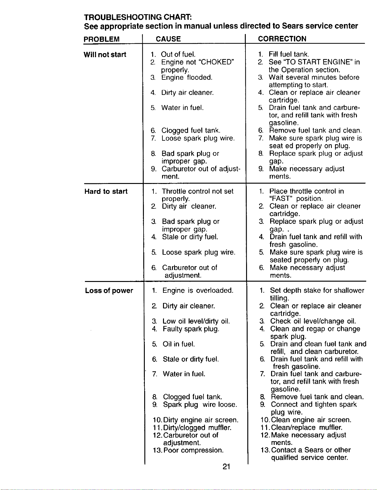
TROUBLESHOOTING CHART:
See appropriate section in manual unless directed to Sears service center
PROBLEM
Will not start
Hard to start
Loss of power
CAUSE
1. Out of fuel.
2. Engine not "CHOKED"
properly.
3. Engine flooded.
4. Dirty air cleaner.
5. Water in fuel.
6. Clogged fuel tank.
7. Loose spark plug wire.
8. Bad spark plug or
improper gap.
9. Carburetor out of adjust-
ment.
1, Throttle control not set
properly.
2. Dirty air cleaner.
3. Bad spark plug or
improper gap.
4. Stale or dirty fuel.
5. Loose spark plug wire.
6. Carburetor out of
adjustment.
1. Engine is overloaded.
2. Dirty air cleaner.
3. Low oil level/dirty oil.
4. Faulty spark plug.
5. Oil in fuel.
6. Stale or dirty fuel.
7. Water in fuel.
8. Clogged fuel tank.
9. Spark plug wire loose,
10.Dirty engine air screen.
11 .Dirty/clogged muffler.
12.Carburetor out of
adjustment.
13. Poor compression.
21
CORRECTION
1. Fill fuel tank.
2. See "TO START ENGINE" in
the Operation section.
3. Wait several minutes before
attempting to start.
4. Clean or replace air cleaner
cartridge.
5. Drain fuel tank and carbure-
tor, and refill tank with fresh
gasoline.
6. Remove fuel tank and clean.
7. Make sure spark plug wire is
seat ed properly on plug.
8. Replace spark plug or adjust
gap.
9. Make necessary adjust
merits.
1. Place throttle control in
"FAST" position.
2, Clean or replace air cleaner
cartridge.
3. Replace spark plug or adjust
gap..
4. Drain fuel tank and refill with
fresh gasoline.
5. Make sure spark plug wire is
seated properly on plug.
6. Make necessary adjust
ments.
1. Set depth stake for shallower
tilling.
2. Clean or replace air cleaner
cartridge.
3. Check oil level/change oil.
4. Clean and regap or change
spark plug.
5. Drain and clean fuel tank and
refill, and clean carburetor.
6. Drain fuel tank and refill with
fresh gasoline.
7. Drain fuel tank and carbure-
tor, and refill tank with fresh
gasoline.
8. Remove fuel tank and clean.
9. Connect and tighten spark
plug wire.
10,Clean engine air screen.
11.Clean/replace muffler,
12.Make necessary adjust
ments.
13. Contact a Sears or other
qualified service center.
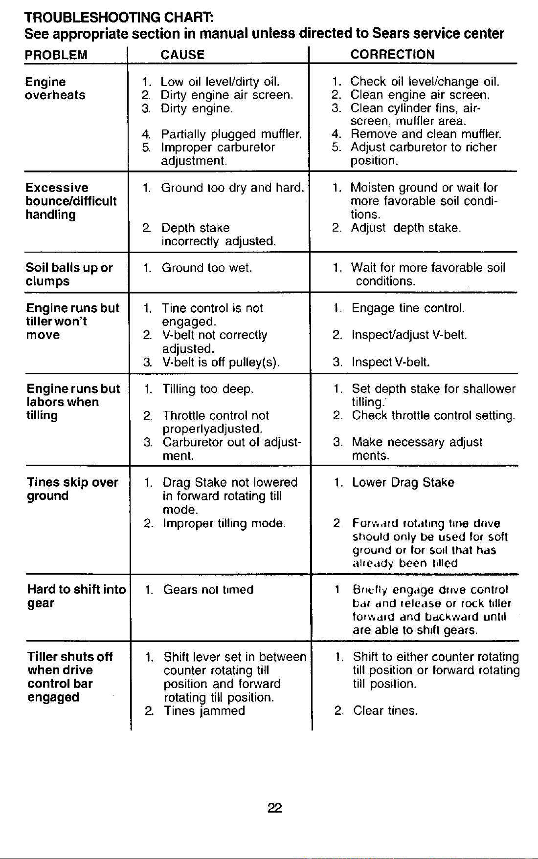
TROUBLESHOOTING CHART:
See appropriate section in manual unless directed to Sears service center
PROBLEM
Engine
overheats
Excessive
bounce/difficult
handling
Soil balls up or
clumps
Engine runs but
tiller won't
move
Engine runs but
labors when
tilling
Tines skip over
ground
CAUSE
1. Low oil level/dirty oil.
2. Dirty engine air screen.
3. Dirty engine.
Hard to shift into
gear
Tiller shuts off
when drive
control bar
engaged
4. Partially plugged muffler.
5. Improper carburetor
adjustment.
1. Ground too dry and hard.
2_
Depth stake
incorrectly adjusted.
1. Ground too wet.
,
2.
3.
1.
2.
3.
Tine control is not
engaged.
V-belt not correctly
adjusted.
V-belt is off pulley(s).
Tilling too deep.
Throttle control not
properlyadjusted.
Carburetor out of adjust-
ment.
1. Drag Stake not lowered
in forward rotating till
mode.
2. Improper tilling mode
1. Gears not I=med
1. Shift lever set in between
counter rotating till
position and forward
rotating till position.
2. Tines jammed
CORRECTION
1. Check oil level/change oil.
2. Clean engine air screen.
3. Clean cylinder fins, air-
screen, muffler area.
4. Remove and clean muffler.
5. Adjust carburetor to richer
position.
1. Moisten ground or wait for
more favorable soil condi-
tions.
2. Adjust depth stake.
1. Wait for more favorable soil
conditions.
1. Engage tine control.
2. Inspect/adjust V-belt.
3. Inspect V-belt.
1. Set depth stake for shallower
tilling.
2. Check throttle control setting.
3. Make necessary adjust
ments.
1. Lower Drag Stake
2
For,.',,,fd fotahng t_ne d.ve
should only be used for soft
ground or for SOd lhat has
ahe,Jdy been Idled
Bf=_.,fly engage drgve conlrol
bar and release or r(x;k Idler
for_',afd and backward until
are able to shrft gears.
1. Shift to either counter rotating
till position or forward rotating
till position.
2. Clear tines.
22
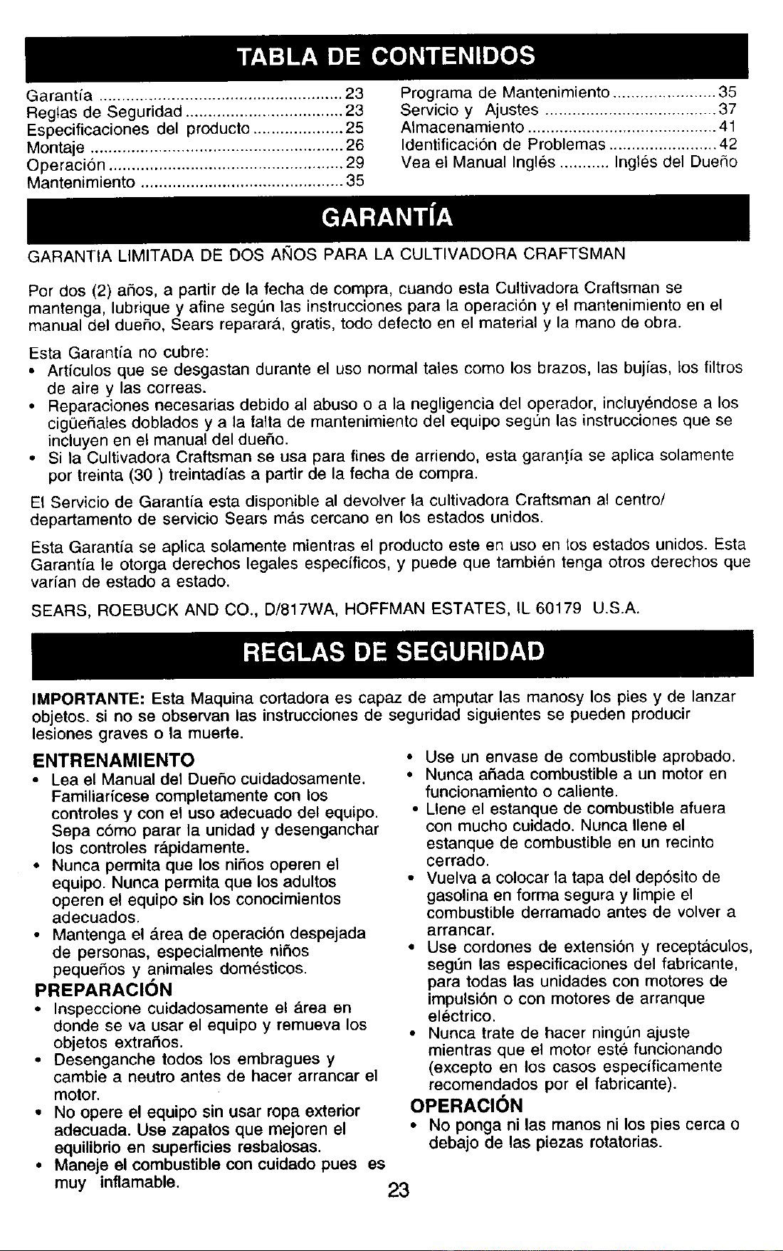
Garant/a ...................................................... 23
Reglas de Seguridad ................................... 23
Especificaciones del producto .................... 25
Montaje ........................................................ 26
Operacion .................................................... 29
Mantenimiento ............................................. 35
Programa de Mantenimiento ....................... 35
Servicio y Ajustes ...................................... 37
Almacenamiento .......................................... 41
Identificaci6n de Problemas ........................ 42
Vea el Manual Ingles ........... Ingles del DueSo
GARANTIA LIMITADA DE DOS AhlOS PARA LA CULTIVADORA CRAFTSMAN
Por dos (2) aSos, a partir de la fecha de compra, cuando esta Cultivadora Craftsman se
mantenga, lubrique y afine seg0n las instrucciones para la operaci6n y el mantenimiento en el
manual del duefio, Sears reparar_,, gratis, todo defecto en el material y la mano de obra.
Esta Garantia no cubre:
• Articulos que se desgastan durante el uso normal tales como los brazos, las bujias, los filtros
de aire y las correas.
• Reparaciones necesarias debido al abuso o a la negligencia del operador, incluyendose a los
cig0efiates doblados y a la falta de mantenimiento del equipo segun las instrucciones que se
incluyen en el manual del dueSo.
• Si la Cultivadora Craftsman se usa para fines de arriendo, esta garantia se aplica solamente
por treinta (30) treintadias a partir de la fecha de compra.
El Servicio de Garantia esta disponible al devolver la cultivadora Craftsman al centro/
departamento de servicio Sears mas cercano en los estados unidos.
Esta Garantia se aplica solamente mientras el producto este en uso en los estados unidos. Esta
Garantia le otorga derechos legales especfficos, y puede que tambien tenga otros derechos que
varian de estado a estado.
SEARS, ROEBUCK AND CO., D/817WA, HOFFMAN ESTATES, IL 60179 U.S.A.
IMPORTANTE: Esta Maquina cortadora es capaz de amputar las manosy los pies y de lanzar
objetos, si no se observan las instrucciones de seguridad siguientes se pueden producir
lesiones graves o la muerte.
ENTRENAMIENTO
• Lea el Manual del Duefio cuidadosamente.
Familiaricese completamente con los
controles y con el uso adecuado del equipo.
Sepa c6mo parar la unidad y desenganchar
los controles r&pidamente.
• Nunca permita que los ni_os operen el
equipo. Nunca permita que los adultos
operen el equipo sin los conocimientos
adecuados.
• Mantenga el &rea de operaci6n despejada
de personas, especialmente nifios
pequeSos y animales domesticos.
PREPARACION
• Inspeccione cuidadosamente ei _.rea en
donde se va usar el equipo y remueva los
objetos extrados.
• Desenganche todos los embragues y
cambie a neutro antes de hacer arrancar el
motor.
• No opere el equipo sin usar ropa exterior
adecuada. Use zapatos que mejoren el
equilibdo en superficies resbalosas.
• Maneje el combustible con cuidado pues es
muy inflamable.
• Use un envase de combustible aprobado.
• Nunca aSada combustible a un motor en
funcionamiento o caliente.
• Llene el estanque de combustible afuera
con mucho cuidado. Nunca Ilene el
estanque de combustible en un recinto
cerrado.
• Vuelva a colocar la tapa del dep6sito de
gasolina en forma segura y limpie el
combustible derramado antes de volver a
arrancar.
• Use cordones de extensi6n y receptaculos,
seg0n las especificaciones del fabricante,
para todas las unidades con motores de
impulsi6n o con motores de arranque
electrico.
• Nunca trate de hacer ning0n ajuste
mientras que el motor este funcionando
(excepto en los casos especificamente
recomendados por el fabricante).
OPERACI(_N
• No ponga ni las manos ni los pies cerca o
debajo de las piezas rotatorias.
23
•Tenga mucho cuidado cuando opere o
cruce entradas para automoviles de ripio,
senderos o caminos. Este alerta en Io que
se refiere a los peligros escondidos o al
tr&fico. No Ileve pasajeros.
Despues de pegarle a un objeto extrafio,
pare el motor, remueva el alambre de la
bujia, inspeccione la cultivadora
cuidadosamente, para verificar si hay
dafios, y repare el dafio antes de volver a
arrancar y operar la cultivadora.
lenga cuidado l_c_,._evitar resbalarse o
,aerse
• Si la unidad empieza a vibrar anormalmente,
pare el motor y revisela inmediatamente
para verificar la causa. La vibracion
normalmente es un aviso de problemas.
• Pare el motor cuando abandone la posicion
de operaci6n.
• Tome todas las precauciones posibles
cuando deje la maquina desatendida.
Desenganche los brazos, cambie a neutro
y pare el motor.
• Antes de limpiar, reparar e inspeccionar,
apague el motor y asegQrese que todas las
parfes en movimiento se han detenido.
Desconecte el alambre de la bujfa, y
mantengalo alejado de esta para evitar el
arranque por accidente. Desconecte el
cordon en los motores electricos.
• No haga funcionar el motor en recintos
cerrados; los gases de escape son
peligrosos.
• Nunca opere la cultivadora sin las
protecciones, y las planchas adecuadas y
sin los demas dispositivbs de seguridad en
su lugar.
• Mantenga a los nifios y a los animales
domesticos alejados.
• No sobrecargue la capacidad de la
maquina, tratando de cultivar a mucha
profundidad, muy rapido.
• Nunca opere la ma.quina a altas velocidades
en superficies resbalosas. Mire hacia atras
y tonga cuidado cuando retroceda.
• Nunca permita la presencia de
espectadores cerca de la unidad.
• Use solamente accesorios y aditamentos
para la oultivadora aprobados pot el
fabricante.
• Nunca opere la cultivadora sin buena
visibilidad o luz.
•Tenga cuidado al cultivar en terreno duro.
Los brazos pueden quedarse agarrados en
el suelo e impulsar a la cultivadora hacia
adelante. Si esto sucede, suelte los mangos
y no restrinja la ma.quina.
MANTENIMIENTO Y
ALMACENAMIENTO
• Mantenga los ac_sorios y aditamentos de
la ma.quina en buenas condiciones para el
funcionamiento.
• Revise las clavijas de seguro, los pernos de
montaje del motor y otros pemos, a
intervalos frecuentes, para verificar si esta.n
apretados en forma segura y asegurarse
que el equipo este en buenas condiciones
de funcionamiento.
• Nunca guarde I:t m#lquina con combustible
_1estallq_,t _ _.ombustible dentro de un
edificio en donde hay fuentes de ignicion
presentes, tales como calentadores de
agua o del ambiente, secadoras de ropa u
otros artefactos parecidos. Permita que se
enfrfe el motor antes de guardarlo en alg0n
lugar cerrado.
• Siempre refierase a las instrucciones en la
guia del operador para vet los detalles de
importancia si la cultivadora va a set
guardada por un perfodo de tiempo largo.
_,Busque este simbolo que sefiala las
precauciones de seguridad, de importancia.
Quiere decir- iiiATENClON!!! iiiESTE
ALERTO!I! SU SEGURIDAD ESTA COMPRO-
METIDA.
At,PRECAUOII_N" Siempre desconecte el
alambre de la bujia y pongalo donde no pueda
entrar en contacto con la bujfa, para evitar el
arranque per accidente, durante la
preparaci6n, el transporte, el ajuste o cuando
se hacen reparaciones.
_IADVERTENCIA: El tubo de escape del
motor, algunos de sus constituyentes y
algunos componentes del vehiculo contienen
o desprenden productos quimicos conocidos
en el Estado de California como causa de
cancer y defectos al nacimiento u otros dafios
reproductivos.
24
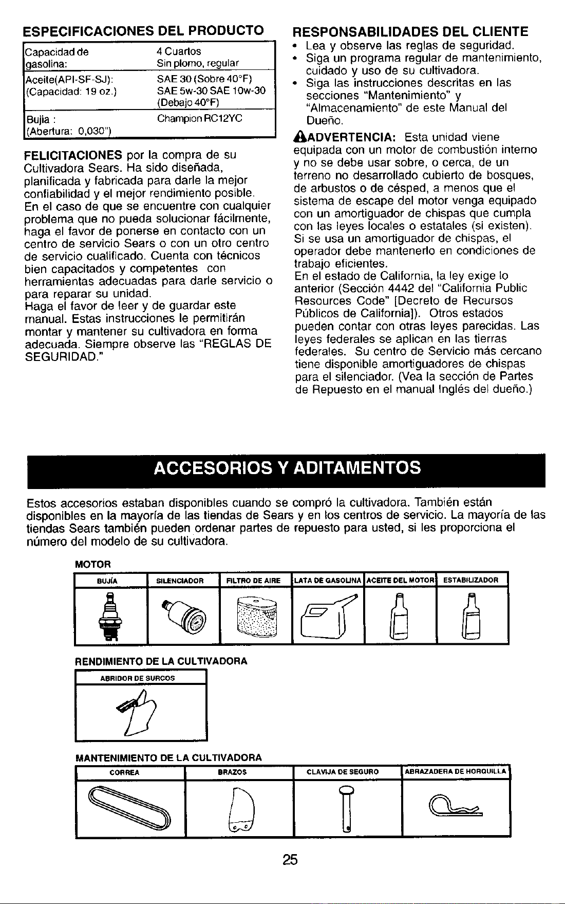
ESPECIFICACIONES DEL PRODUCTO
.3apacidad de 4 Cuartos
;]asolina: Sin plomo, regular
t_ceite(API-SF-SJ): SAE 30 (Sobre 40°F)
(Capacidad: 19 oz.) SAE 5w-30 SAE 10w-30
(Debajo 40°F)
Bujia : Champion RC12YC
(Abertura: 0,030")
FELIClTAClONES por la compra de su
Cultivadora Sears. Ha sido disefiada,
planificada y fabricada para darle la mejor
confiabilidad y el mejor rendimiento posible.
En el caso de que se encuentre con cualquier
problema que no pueda solucionar f_cilmente,
haga el favor de ponerse en contacto con un
centro de servicio Sears o con un otro centro
de servicio cuatificado. Cuenta con tecnicos
bien capacitados y competentes con
herramientas adecuadas para darle servicio o
para reparar su unidad.
Haga el favor de leer y de guardar este
manual. Estas instrucciones le permitiran
montar y mantener su cultivadora en forma
adecuada. Siempre observe las "REGLAS DE
SEGURIDAD."
RESPONSABILIDADES DEL CLIENTE
• Lea y observe las reglas de segufidad.
• Siga un programa regular de mantenimiento,
cuidado y uso de su cultivadora.
• Siga las instrucciones descritas en las
secciones "Mantenimiento" y
"Almacenamiento" de este Manual del
Duefio.
_kADVERTENCIA: Esta unidad viene
equipada con un motor de combusti6n interno
y no se debe usar sobre, o cerca, de un
terreno no desarrollado cubierto de bosques,
de arbustos o de cesped, a menos que el
sistema de escape del motor venga equipado
con un amortiguador de chispas que cumpla
con las leyes locales o estatales (si existen).
Si se usa un amortiguador de chispas, el
operador debe mantenerlo en condiciones de
trabajo eficientes.
En el estado de California, la ley exige Io
anterior (Secci6n 4442 del "California Public
Resources Code" [Decreto de Recursos
P0blicos de California]). Otros estados
pueden contar con otras leyes parecidas. Las
leyes federales se aplican en las tierras
federales. Su centro de Servicio mas cercano
tiene disponible amortiguadores de chispas
para el silenciador. (Vea la secci6n de Partes
de Repueste en el manual Ingles del dueSo.)
Estos accesorios estaban disponibles cuando se compro la cultivadora. Tambi6n est&n
disponibles en la mayorfa de las tiendas de Sears yen los centros de servicio. La mayorfa de las
tiendas Sears tambi_n pueden ordenar partes de repuesto para usted, si les proporciona el
n0mero del modelo de su cultivadora.
MOTOR
BUJ_A SILENCOAOOR FILTRO OE AIRE LATA OE GASOUNA ACEITE DEL MOTOR
RENDIMIENTO DE LA CULTIVADORA
ABRIDOR DE SURCOS
ESTABFUZADOR
MANTENIMIENTO DE LA CULT|VADORA
CORREA BRAZOS CLAVUA OE SEGURO ABRAZADERA DE HORQUtLLA
25
Su cultivadora nueva ha sido montada en la
f_,brica, con la excepcion de aquellas partes
que se dejaron sin montar por razones de
envio. Para asegurarse que la cultivadora
operara en forma segura y adecuada, todas
las partes y los articulos de ferreteria que
monte tienen que estar apretados en forma
segura. Use las herramientas correctas,
segt_n sea necesario, para asegurarse de que
queden apretadas en forma segura.
HERRAMIENTA8 NECESARIAS PARA
EL MONTAJE
Se le facilitara el montaje si cuenta con un
juego de Ilaves de tubo. Se han enumerado los
tamafios est_,ndar de las Ilaves.
(1) Cuchillo para todo uso
(1) Cortador de alambres
(1) Destornillador
(1) Medidor de presion de las Ilantas
(1) Par de alicates
(1) Llave de 9/16"
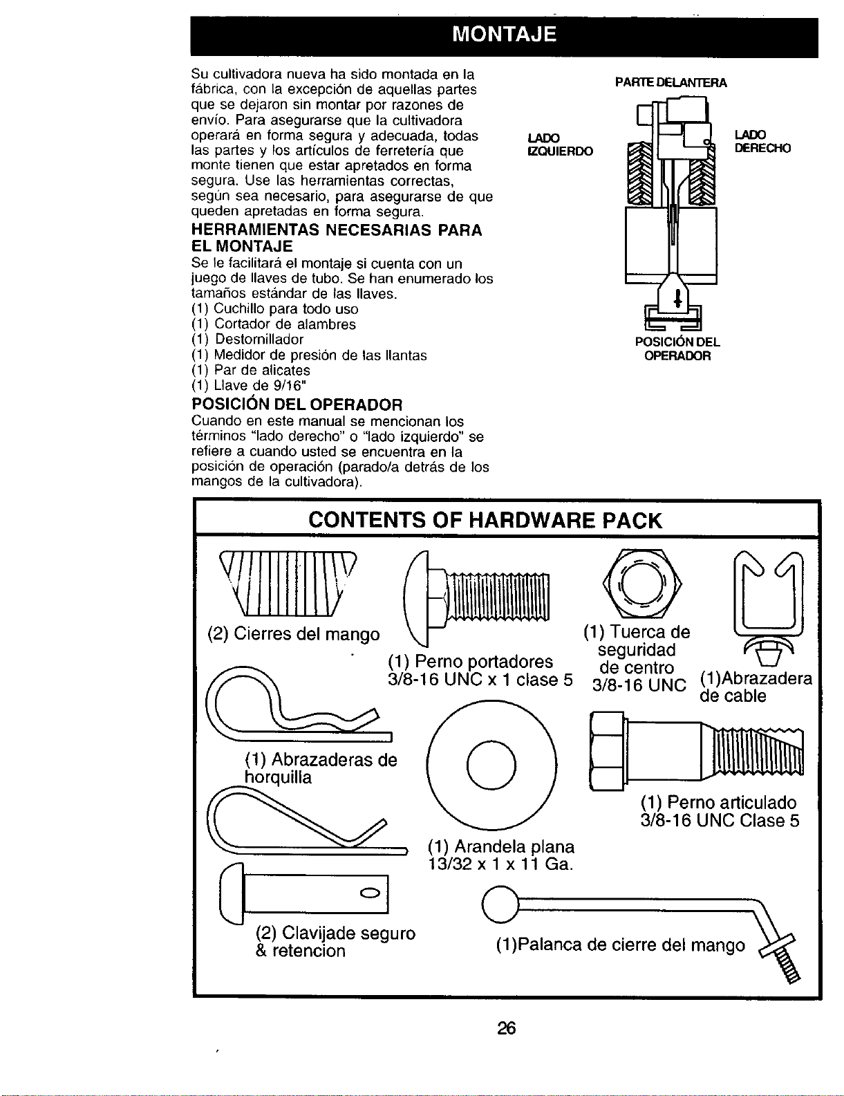
POSICION DEL OPERADOR
Cuando en este manual se mencionan los
terminos "lado derecho" o "lado izquierdo" se
refiere a cuando usted se encuentra en la
posicion de operaci6n (parado/a detrAs de los
mangos de la cultivadora).
LADO
IZQUIERDO
PARTE DELANTERA
DERECHO
1
POSICIONDEL
OPERADOR
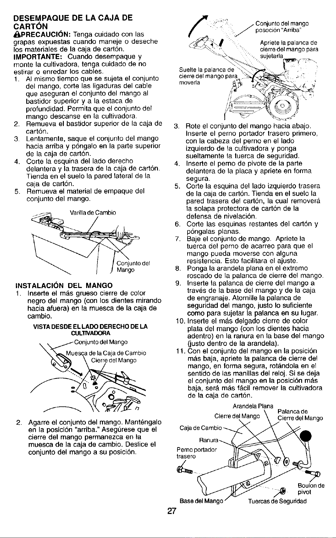
CONTENTS OF HARDWARE PACK
/IIIIIT
(2) Cierres del mango
(1) Abrazaderas de
°1
(2) Clavijade seguro
& retencion
(1) Perno portadores
3/8-16 UNC x 1 clase 5
(1) Arandela plana
13/32xlx11Ga.
Q
(1) Tuerca de
seguridad
de centro
3/8-16 UNC
(1)Abrazadera
de cable
(1) Perno articulado
3/8-16 UNC Clase 5
©
(1)Palanca de cierre del mango
26
DESEMPAQUE DE LA CAJA DE
CARTON
_IPRECAUCI6N: Tenga cuidado con las
grapas expuestas cuando maneje o deseche
los materiales de la caja de cart6n.
IMPORTANTE: Cuando desempaque y
monte la cultivadora, tenga cuidado de no
estirar o enredar los cables.
1. AI mismo tiempo que se sujeta el conjunto
del mango, corte las ligaduras del cable
que aseguran el conjunto del mango al
bastidor superior y a la estaca de
profundidad. Permita que el cenjunto del
mango descanse en la cultivadora.
2. Remueva el bastidor superior de la caja de
cart6n.
3. Lentamente, saque el conjunto del mango
hacia arriba y p6ngalo en la parte superior
de la caja de cart6n.
4. Corte la esquina del lade derecho
delantera y la trasera de la caja de carton.
Tienda en el suelo la pared lateral de la
caja de cart6n.
5. Remueva el material de empaque del
conjunto del mango•
VarilladeCambio
Con junto del
Mango
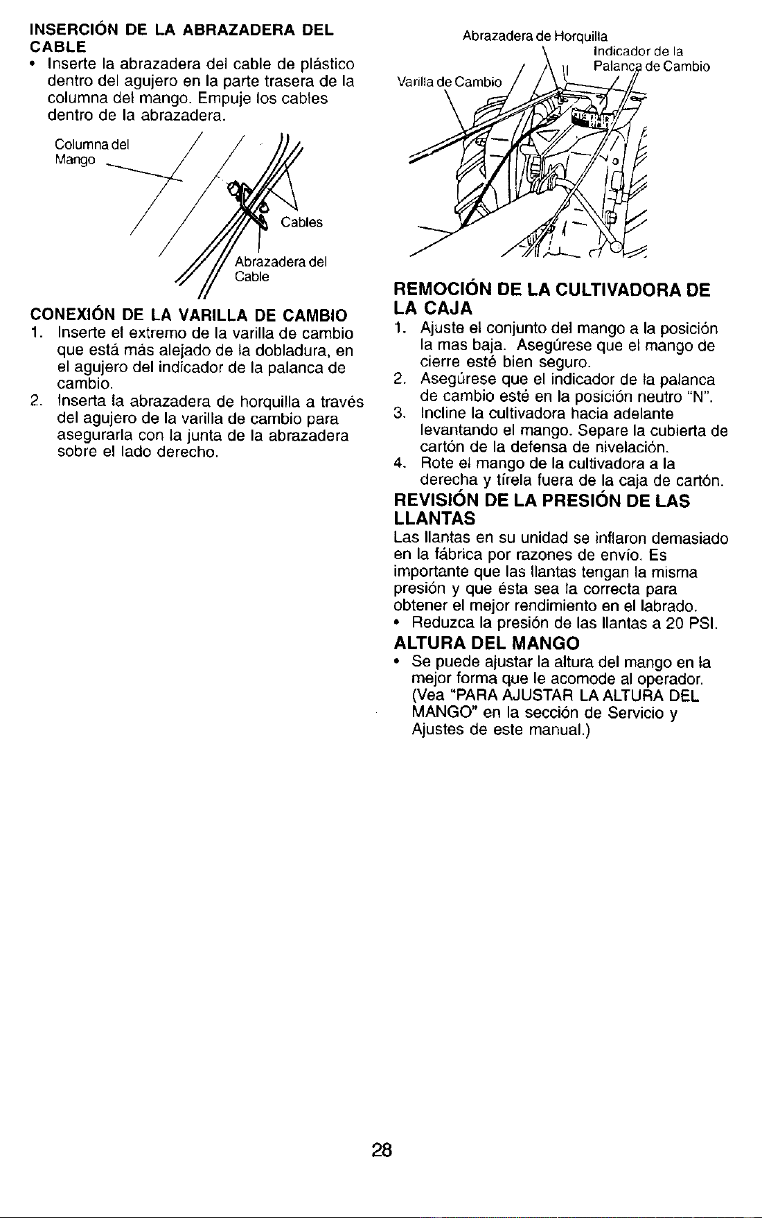
INSTALACI6N DEL MANGO
1. Inserte el m_,s grueso cierre de color
negro del mango (con los dientes mirando
hacia afuera) en la muesca de la caja de
cambio.
VISTA DESDE EL LADO DERECHO DE LA
CUL11VADORA
._.M. uCOnjuntodel Mango
escade la Caja de Cambio
Cier.rede1Mango
,
Agarre el conjunto del mango. Mantengalo
en la posici6n "arriba." Asegl_rese que el
cierre del mango permanezca en la
muesca de la caja de cambio. Deslice el
conjunto del mango a su posici6n.
_._ : _;';!!_:_: /- Conjuntodel mango
• .J posocion "Arriba
_ _,. Apriete la palanca de
"_' -+_ " cierre del mango para
_-_._ sujetar a
Sueltela palanca de _\_ _. "
cierredelmangopara :_ i .:..71 !
movefla _,_ _t-.,_.'b!_--._,
3. Rote el conjunto del mango hacia abajo.
Inserte el perno portador irasere primero,
con la cabeza del perno en el lado
izquierdo de ta cultivadora y ponga
sueltamente ta tuerca de seguridad.
4. Inserte el perno de pivote de la parte
delantera de la placa y apriete en forma
segura.
5. Corte la esquina del lade izquierdo trasera
de la caja de cart6n. Tienda en el suelo la
pared trasera del cart6n, la cual remover_l
ta solapa protectora de cart6n de la
defensa de nivelaci6n.
6. Corte las esquinas restantes del carton y
p6ngalas planas.
7. Baje el conjunto de mango. Apriete la
tuerca det pemo de acarreo para que el
mango pueda moverse con alguna
resistencia. Esto facilitara el ajuste.
8. Ponga la arandela plana en el extreme
roscado de ta palanca de cierre del mango•
9. Inserte la palanca de cierre del mango a
traves de la base det mango y de la caja
de engranaje. Atornitle la palanca de
seguridad del mango, lusto Io suficiente
come para sujetar la palanca en su lugar.
10. Inserte el m_.s delgado cierre de color
plata del mango (con los dientes hacia
adentro) en la ranura en la base del mango
(justo dentro de la arandela).
11. Con el conjunto del mango en la posici6n
mAs baja, apriete la palanca de cierre del
mango, en forma segura, rot&ndola en el
sentido de las manillas del reloj. Si se deja
el conjunto del mango en la posici6n mas
baja, serA m&s fAcil remover la cultivadora
de la caja de carton.
Arandela Plana
Palanca de
Cierre del Mango Cierre del Mango
Caj_
Ranura_
Pemo portador
trasero
27
Boulon de
_ pivot
Tuercas deSeguddad
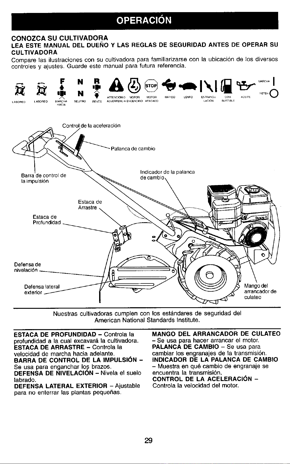
INSERCI(_N DE LA ABRAZADERA DEL
CABLE
• Inserte la abrazadera del cable de plastico
dentro del agujero en la parte trasera de la
columna det mango. Empuje los cables
dentro de la abrazadera.
Columnadel
Mango
Abrazadera de Horquilla
Indicador de la
I de Cambio
Varilla de Cambio
Cables
Abrazadera del
Cable
CONEXlON DE LA VARILLA DE CAMBIO
1. Inserte el extremo de la varilla de cambio
que estgt mas alejado de la dobladura, en
el agujero del indicador de la palanca de
cambio.
2. Inserta la abrazadera de horquilla a traves
del agujero de la varilla de cambio para
asegurarla con la junta de la abrazadera
sobre el lado derecho.
REMOCION DE LA CULTIVADORA DE
LA CAJA
1. Ajuste el conjunto del mango a la posicion
lamas baja. Asegt_rese que el mango de
cierre est6 bien seguro.
2. AsegQrese que el indicador de ta palanca
de cambio este en la posici6n neutro "N".
3. Incline la cultivadora hacia adelante
levantando el mango. Separe la cubierta de
cart6n de la defensa de nivelaci6n.
4. Rote et mango de la cultivadora a la
derecha y tirela fuera de la caja de carton.
REVISION DE LA PRESION DE LAS
LLANTAS
Las Ilantas en su unidad se inflaron demasiado
en la f&brica por razones de envio. Es
importante que las Ilantas tengan la misma
presi6n y que esta sea la correcta para
obtener el mejor rendimiento en el labrado.
• Reduzca la presi6n de las Ilantas a 20 PSI.
ALTURA DEL MANGO
• Se puede ajustar la altura del mango en ta
mejor forma que le acomode al operador.
(Vea "PARA AJUSTAR LA ALTURA DEL
MANGO" en la secci6n de Servicio y
Ajustes de este manual.)
28
CONOZCA SU CULTIVADORA
LEA ESTE MANUAL DEL DUEI_IO Y LAS REGLAS DE SEGURIDAD ANTES DE OPERAR SU
CULTIVADORA
Compare las ilustraciones con su cultivadora para familiarizarse con la ubicaci6n de los diversos
controles y ajustes. Guarde este manual para futura referencia.
N _' A_ENC=6N O taOTO_ MOTOR LENTO ESTRA_dGU COI,I ACEITE
LABOREO L_,BOREO M,tRCHA NEUI"RO R_V_S A[3V£RTEN¢IA ENCEN01DO M_,GAt30 L_ClON BUSTLBLE
Control de la aceleraci6n
Palanca de cambio
Barra de control de
la impulsi6n
Indicador de la palanca
de cambio
Estaca de
Estaca de
Profundidad
Defensa de
nivelaci6n
Defensalateral
Mango del
arrancador de
culateo
Nuestras cultivadoras cumplen con los estAndares de seguridad del
American National Standards Institute.
ESTACA DE PROFUNDIDAD - Controla la
profundidad a la cual excavar& la cultivadora.
ESTACA DE ARRASTRE - Controla la
velocidad de marcha hacia adelante.
BARRA DE CONTROL DE LA IMPULSION -
Se usa para enganchar Io.s brazos.
DEFENSA DE NIVELAClON - Nivela el suelo
labrado.
DEFENSA LATERAL EXTERIOR - Ajustable
para no enterrar las plantas pequefias.
MANGO DEL ARRANCADOR DE CULATEO
- Se usa para hacer arrancar el motor.
PALANCA DE CAMBIO - Se usa para
cambiar los engranajes de la transmisi6n.
INDICADOR DE LA PALANCA DE CAMBIO
- Muestra en qu_ cambio de engranaje se
encuentra la transmisi6n.
CONTROL DE LA ACELERAClON -
Controla la velocidad del motor.
29
La operaci6n de cualquier cultivadora puede bacer que salten objetos extra5os
dentro de sus ojos, Io que puede producir daSos graves en estos. Siempre use
anteojos de seguridad o protecciones para los ojos antes de hacer arrancar su
cultivadora o mientras este labrando con ella. Recomendamos gafas de
seguridad o una mascara de vision amplia de seguridad usada sobre las gafas.
COMO USAR SU CULTIVADORA
Sepa c6mo operar todos los controles antes
de agregar combustible y aceite o antes de
tratar de hacer arrancar el motor.
PARADA
BRAZOS Y LA IMPULSION
1. Suelte la barra de control de la impulsi6n
para parar el movimiento.
2. Mueva la palanca de cambio a la posicion
de neutro ("N").
MOTOR
• Mueva el control de la aceleraci6n a la
posicion de "PARADA" (STOP). Si equipado
con un interruptor de parada, mueva el
interruptor a la posici6n de "PARADA"
(STOP).
AMISO: Nunca use la estrangulaci6n para
parar el motor.
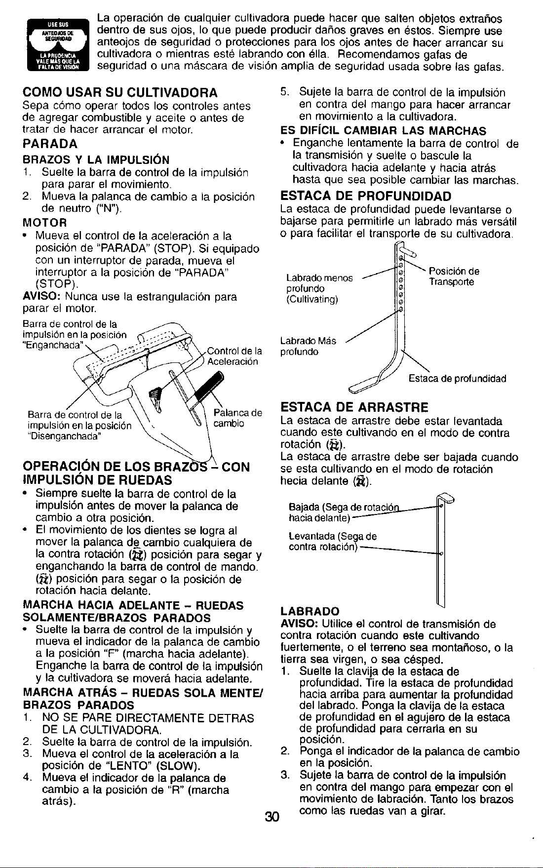
Barra de control de la
impulsi6n en la posicion
"Engarlchada" -,
,Control de la
) Aceleraci6n
5. Sulete la barra de control de la impulsi6n
en contra del mango para hacer arrancar
en movimiento a la cultivadora.
ES DIFiCIL CAMBIAR LAS MARCHAS
• Enganche lentamente la barra de control de
la transmisi6n y suelte o bascule la
cultivadora hacia adelante y hacia atras
hasta que sea posible cambiar las marchas,
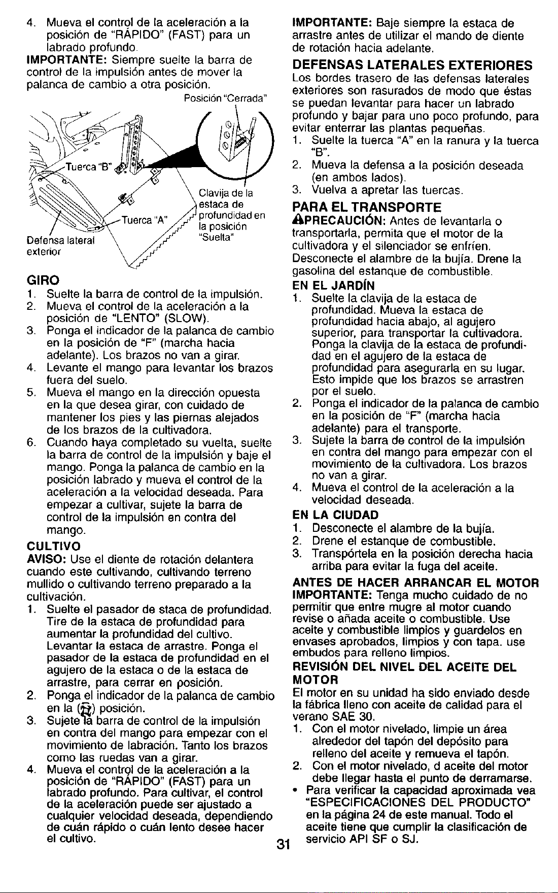
ESTACA DE PROFUNDIDAD
La estaca de profundidad puede levantarse o
bajarse para permitirle un labrado mas vers&til
o para facilitar el transporte de su cultivadora.
Labrado menos
profundo
(Cultivating)
Transporte
Labrado Mas
profundo
Estaca de profundidad
Barra de control de la
impulsi6n en la posici6n
"Disenganchada"
Palanca de
cambio
OPERACION DE CON
IMPULSION DE RUEDAS
• Siempre suelte la barra de control de la
impulsi6n antes de mover la palanca de
cambio a otra posici6n.
• El movimiento de los dientes se Iogra al
mover la palanca de cambio cualquiera de
la contra rotaci6n (_) posici6n para segar y
enganchando la barra de control de mando.
(;_) posicion para segar o la posici6n de
rotaci6n hacia delante.
MARCHA HACIA ADELANTE - RUEDAS
SOLAMENTE/BRAZOS PARADOS
• Suelte la barra de control de la impulsi6n y
mueva el indicador de la palanca de cambio
a la posici6n "F" (marcha hacia adelante).
Enganche la barra de control de la impulsi6n
y la cuttivadora se movera hacia adelante.
MARCHA ATRAS - RUEDAS SOLA MENTE/
BRAZOS PARADOS
1. NO SE PARE DIRECTAMENTE DETRAS
DE LA CULTIVADORA.
2. Suelte la barra de control de la impulsibn.
3. Mueva el control de la aceleracion a la
posici6n de "LENTO" (SLOW).
4. Mueva el indicador de la palanca de
cambio a la posicibn de "R" (marcha
atras).
ESTACA DE ARRASTRE
La estaca de arrastre debe estar levantada
cuando este cultivando en el modo de contra
rotaci6n (_).
La estaca de arrastre debe ser bajada cuando
se esta cultivando en el modo de rotacion
hecia delante (_).
Bajada (Sega de rotaciS_
hacia delante) ----'----
Levantada (Sega de
contra rotaci6n)
30
LABRADO
AVISO: Utilice el control de transmisi6n de
contra rotacion cuando este cultivando
fuertemente, o el terreno sea monta_oso, o la
tierra sea virgen, o sea cesped.
1. Suelte la clavija de la estaca de
profundidad. Tire la estaca de profundidad
hacia arriba para aumentar la profundidad
del labrado. Ponga la clavija de la estaca
de profundidad en el agujero de la estaca
de profundidad para cerrarla en su
posici6n.
2. Ponga el indicador de la palanca de cambio
en la posicion.
3. Sujete la barra de control de la impulsi6n
en contra del mango para empezar con el
movimiento de labracibn. Tanto los brazos
como las ruedas van a girar.
4. Mueva el control de la aceleraci6n a la
posici6n de "RAPIDO" (FAST) para un
labrado profundo.
IMPORTANTE: Siempre suelte la barra de
control de la impulsi6n antes de mover la
palanca de cambio a otra posici6n.
Posici6n"Cerrada"
_ _-_ _ _, Cla_ijadela
_ _ /_estacade
_ -T,,_,,-_"^" JJ profundidad en
/ .... "/Y !a.p°si
Defe?sa lateral \ fj-" "Suelta'
extenor
GIRO
1. Suelte la barra de control de la impulsi6n.
2. Mueva el control de la aceleracion a la
posicion de "LENTO" (SLOW).
3. Ponga el indicador de la palanca de cambio
en la posici6n de "F" (marcha hacia
adelante). Los brazos no van a girar.
4. Levante el mango para levantar los brazos
fuera del suelo.
5. Mueva el mango en la direcci6n opuesta
en la que desea girar, con cuidado de
mantener los pies y las piernas alejados
de los brazos de la cultivadora.
6. Cuando haya completado su vuelta, suelte
la barra de control de la impulsi6n y baje el
mango. Ponga la palanca de cambio en la
posici6n labrado y mueva el control de la
aceleraci6n a la velocidad deseada. Para
empezar a cultivar, sujete la barra de
control de la impulsi6n en contra del
mango.
CULTIVO
AMISO: Use el diente de rotaci6n delantera
cuando este cultivando, cultivando terreno
mullido o cultivando terreno preparado a la
cultivaci6n.
1. Suelte el pasador de staca de profundidad.
Tire de la estaca de profundidad para
aumentar la profundidad del cultivo.
Levantar la estaca de arrastre. Ponga el
pasador de la estaca de profundidad en el
agujero de la estaca o de la estaca de
arrastre, para cerrar en posicibn.
2. Ponga el indicador de la palanca de cambio
en la (_t) posici6n.
3. Sujete]& barra de control de la impulsion
en contra del mango para empezar con el
movimiento de labraci6n. Tanto los brazos
como las ruedas van a girar.
4. Mueva el contr?l de la aceleraci6n a la
posicibn de "RAPIDO" (FAST) para un
labrado profundo. Para cultivar, el control
de la aceleraci6n puede ser ajustado a
cualquier velocidad deseada, dependiendo
de cu&n rdpido o cu_.n lento desee hacer
el cultivo.
31
IMPORTANTE: Baje siempre la estaca de
arrastre antes de utilizar el mando de diente
de rotaci6n hacia adelante.
DEFENSAS LATERALES EXTERIORES
Los bordes trasero de las defensas laterales
exteriores son rasurados de modo que estas
se puedan levantar para hacer un labrado
profundo y bajar para uno poco profundo, para
evitar enterrar las plantas pequeSas.
1. Suelte la tuerca "A" en la ranura y la tuerca
4'B7' "
2. Mueva la defensa a la posici6n deseada
(en ambos lados).
3. Vuelva a apretar las tuercas.
PARA EL TRANSPORTE
_,PRECAUCl6N: Antes de levantarla o
transportarla, permita que el motor de la
cultivadora y el silenciador se enfr{en.
Desconecte el alambre de la bujfa. Drene la
gasolina del estanque de combustible.
EN EL JARD|N
1. Suelte la clavija de la estaca de
profundidad. Mueva la estaca de
profundidad hacia abajo, al agujero
superior, para transportar la cultivadora.
Ponga la clavija de la estaca de profundi-
dad en el agujero de la estaca de
profundidad para asegurarla en su lugar.
Esto impide que los brazos se arrastren
por el suelo.
2. Ponga el indicador de la palanca de cambio
en la posici6n de "F" (marcha hacia
adelante) para el transporte.
3. Sujete la barra de control de la impulsi6n
en contra del mango para empezar con el
movimiento de la cultivadora. Los brazos
no van a girar.
4. Mueva el control de la aceleraci6n a la
velocidad deseada.
EN LA ClUDAD
1. Desconecte el alambre de la bujfa.
2. Drene el estanque de combustible.
3. Transp6rtela en la posicibn derecha hacia
arriba para evitar la fuga del aceite.
ANTES DE HACER ARRANCAR EL MOTOR
IMPORTANTE: Tenga mucho cuidado de no
permitir que entre mugre al motor cuando
revise o ahada aceite o combustible. Use
aceite y combustible limpios y guardelos en
envases aprobados, limpios y con tapa. use
embudos para relleno limpios.
REVISI6N DEL NIVEL DEL ACEITE DEL
MOTOR
El motor en su unidad ha sido enviado desde
la fa.brica Ueno con aceite de calidad para el
verano SAE 30.
1. Con el motor nivelado, limpie un area
alrededor del tap6n del depbsito para
relleno del aceite y remueva el tap6n.
2. Con el motor nivelado, d aceite del motor
debe Ilegar hasta el punto de derramarse.
• Para verificar la capacidad aproximada vea
"ESPEClFICAClONES DEL PRODUCTO"
en la p_.gina 24 de este manual. Todo el
aceite tiene que cumplir la clasificaci6n de
servicio API SF o SJ.
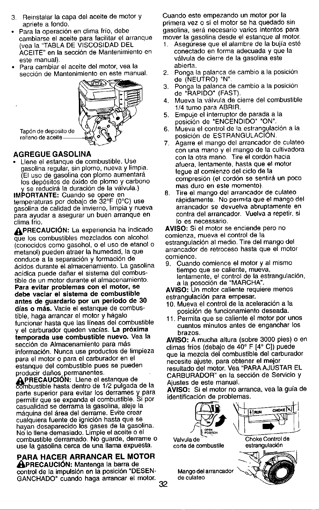
3. Reinstalar la capa del aceite de motor y
apriete a fondo.
• Para la operacion en clima frio, debe
cambiarse el aceite para facilitar el arranque
(vea ta "TABLA DE VISCOSIDAD DEL
ACEITE" en la secci6n de Mantenimiento en
este manual).
• Para cambiar el aceite del motor, vea la
seccion de Mantenimiento en este manual.
Tapon de deposito de
relleno de aceite--
AGREGUE GASOLINA
• Llene el estanque de combustible. Use
gasolina regular, sin plomo, nueva y limpia.
(El use de gasolina con plomo aumentar_.
los dep6sitos de 6xido de plomo y carbono
y se reducir& la duracion de la v_llvula.)
IMPORTANTE: Cuando se opere en
temperaturas per deba o de 32°F (0°C) use
gasoUna de calidad de invierno, limp a y nueva
para ayudar a asegurar un buen arranque en
clima frio.
_PRECAUCl6N: La experiencia ha indicado
que los combustibles mezclados con alcohol
(conecidos come gasohol, e el use de etanol o
metanol) pueden atraer la humedad, la que
conduce a la separaci6n y formaci6n de
_,cidos durante el almacenamiento. La gasolina
acidica puede dafiar el sistema del combus-
tible de un motor durante el almacenamiento.
Para evitar problemas con el motor, se
debe vaciar el sistema de combustible
antes de guardarlo per un pedodo de 30
dias o m,_s. Vacie el estanque de combus-
tible, haga arrancar el motor y h_lgalo
funcionar hasta que las lineas del combustible
y el carburador queden vacias. La pr6xima
temporada use combustible nuevo. Yea la
secci6n de Almacenamiento para m&s
informaci6n. Nunca use productos de limpieza
para el motor o para el carburador en el
estanque del combustible pues se pueden
producir dafios permanentes.
_PRECAUCION: Llene el estanque de
combustible hasta dentro de 1/2 pulgada de la
parte superior para evitar los derrames y para
permitir que se expanda el combustible. Si per
casualidad se derrama la gasolina, aleje la
ma.quina del _lrea del derrame. Evite crear
cualquiera fuente de ignici6n hasta que se
hayan desaparecido los gases de la gasolina.
No !o Ilene demasiado. Limpie el aceite o el
combustible derramado. No guarde, derrame o
use la gasolina cerca de una llama expuesta.
PARA HACER ARRANCAR EL MOTOR
_I, PRECAUCI6N: Mantenga la barra de
control de la impulsi6n en la posici6n "DESEN-
GANCHADO" cuando haga arrancar el motor.
Cuando este empezando un motor per la
primera vez o si e! motor se ha quedado sin
gasolina, sera necesario varies intentos para
mover la gasolina desde el estanque al motor.
1. Asegurese que el alambre de la bujia este
conectado en forma adecuada y que la
v&lvula de cierre de la gasolina este
abierta.
2. Ponga la palanca de cambio a la posici6n
de (NEUTRO) "N".
3. Ponga la palanca de cambio a la posici6n
de "RAPIDO" (FAST).
4. Mueva la v&lvula de cierre del combustible
1/4 turno para ABRIR.
5. Empuje el interrupter de parada a la
posici6n de "ENCENDIDO" "ON".
6. Mueva el control de la estrangulacion a la
posicion de ESTRANGULACION.
7. Agarre el mango del arrancador de culateo
con una mane y el mango de la cultivadora
con la otra mane. Tire el cordon hacia
afuera, lentamente, hasta que el motor
legue al comienzo del ciclo de la
compresion (el cord6n se sentira un poco
mas duro en este memento).
8. Tire el mango del arrancador de culateo
r&pidamente. No permita que el mango del
arrancador se devuelva abruptamente en
contra del arrancador. Vuelva a repetir, si
Io es necessario.
AMISO: Si el motor se enciende pero no
comienza, mueva el control de la
estrangulaci6n al medic. Tire del mango del
arrancador de retroceso hasta que el motor
comience.
9. Cuando comience el motor y al mismo
tiempo que se caliente, mueva,
lentamente, e! control de la estrangulaci6n,
a la posoci6n de "MARCHA".
AVISO: Un motor caliente requiere menos
estrangulaci6n para empesar.
10. Mueva el control de la aceleraci6n a la
posici6n de funcionamiento deseada.
11. Permita que se caliente el motor per unos
cuantos minutes antes de enganchar los
brazes.
AVlSO: A mucha altura (sobre 3000 pies) o en
climas fries (debajo de 40° F [4° C]) puede
que la mezcla del combustible del carburador
necesite ajuste, para obtener el meier
resultado del motor. Vea "PARAAJUSTAR EL
CARBURADOR" en la secci6n de Servicio y
Ajustes de este manual.
AMISO: Si el motor no arranca, vea la guia de
identificacion de problemas.
Valvula de Choke Control de
code de combustile estrangulaek_n
Mango del arrancador _
de culateo
32
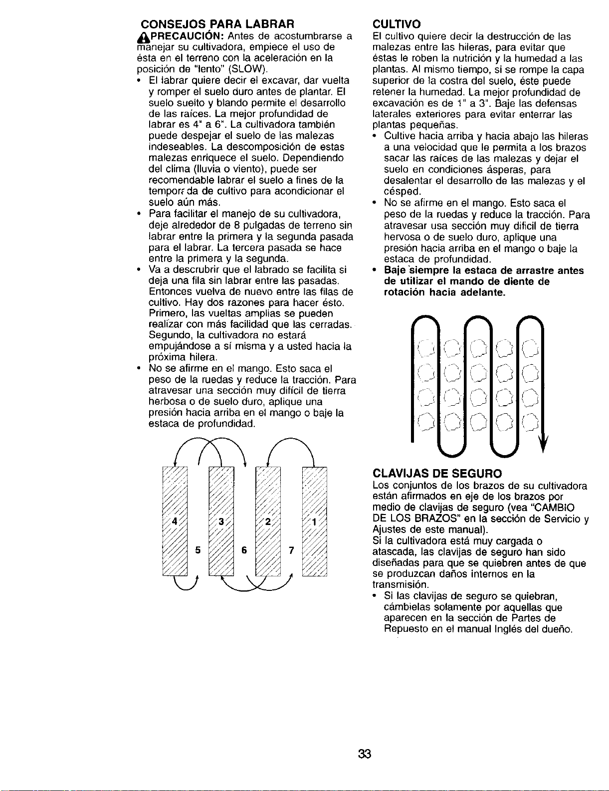
CONSEJOS PARA LABRAR
_,PRECAUCI6N: Antes de acostumbrarse a
manejar su cultivadora, empiece el uso de
esta en el terreno con la aceleracion en la
posici6n de "lento" (SLOW).
• El tabrar quiere decir et excavar, dar vuelta
y romper el suelo duro antes de plantar. El
suelo suelto y blando permite el desarrollo
de las raices. La mejor profundidad de
labrar es 4" a 6". La cultivadora tambien
puede despejar el suelo de las malezas
indeseabtes. La descomposici6n de estas
malezas enriquece el suelo. Dependiendo
del clima (lluvia o viento), puede ser
recomendable labrar el suelo a fines de la
tempor_ da de cultivo para acondicionar el
suelo a6n m,_s.
• Para facilitar el manejo de su cultivadora,
deje alrededor de 8 putgadas de terreno sin
labrar entre la primera y la segunda pasada
para el labrar. La tercera pasada se hace
entre la primera y la segunda.
• Va a descrubrir que el labrado se facilita si
deja una ilia sin labrar entre las pasadas.
Entonces vueIva de nuevo entre las filas de
cultivo. Hay dos razones para hacer esto.
Primero, las vueltas amplias se pueden
realizar con mas facilidad que las cerradas.
Segundo, la cultivadora no estarA
empuj_.ndose a si misma y a usted hacia la
pr6xima hilera.
• No se afirme en el mango. Esto saca el
peso de la ruedas y reduce la tracci6n. Para
atravesar una secci6n muy dificil de tierra
herbosa o de suelo duro, aplique una
presi6n hacia arriba en el mango o baje la
estaca de profundidad.
//
//
CULTIVO
El cultivo quiere decir la destruccion de las
malezas entre las hileras, para evitar que
estas le roben la nutricion y la humedad alas
plantas. AI mismo tiempo, si se rompe la capa
superior de la costra del suelo, este puede
retener la humedad. La mejor profundidad de
excavacion es de 1" a 3". Baje las defensas
laterales exteriores para evitar enterrar las
plantas pequefias.
• Cultive hacia arriba y hacia abajo las hileras
a una velocidad que le permita a los brazos
sacar las raices de las malezas y dejar el
suelo en condiciones _,speras, para
desalentar el desarrollo de las malezas y el
cesped.
• No se afirme en el mango. Esto saca el
peso de la ruedas y reduce la tracci6n. Para
atravesar usa secci6n muy dificil de tierra
hervosa o de suelo duro, aplique una
presi6n hacia arriba en el mango o baje la
estaca de profundidad.
• Baje'siempre la estaca de arrastre antes
de utilizar el mando de diente de
rotacion hacia adelante.
CLAVIJAS DE SEGURO
Los conjuntos de los brazos de su cultivadora
estan afirmados en eje de los brazos por
medio de clavijas de seguro (vea "CAMBIO
DE LOS BRAZOS" en la secci6n de Servicio y
Ajustes de este manual).
Si la cultivadora estd muy cargada o
atascada, las clavijas de seguro han sido
disefiadas para que se quiebren antes de que
se produzcan dafios internos en la
transmisi6n.
• Si las clavijas de seguro se quiebran,
c&mbielas solamente por aquellas que
aparecen en la secci6n de Partes de
Repuesto en el manual Ingles del duefio.
33
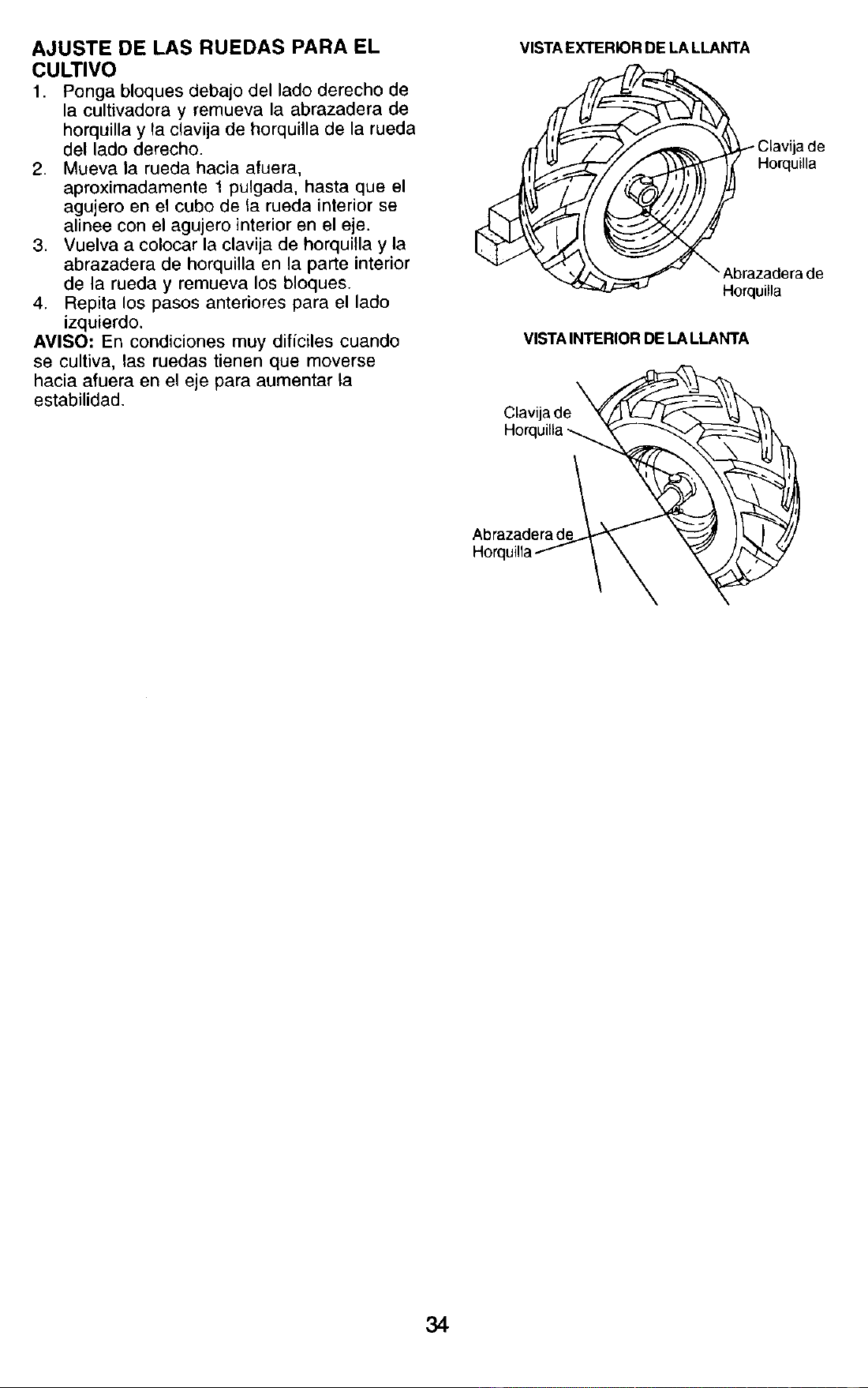
AJUSTE DE LAS RUEDAS PARA EL
CULTIVO
1. Ponga bloques debajo del lado derecho de
la cultivadora y remueva la abrazadera de
horquilla y la clavija de horquilla de la rueda
del lado derecho.
2. Mueva la rueda hacia afuera,
aproximadamente 1 pulgada, hasta que el
agujero en el cubo de la rueda interior se
alinee con el agujero interior en el eje.
3. Vuelva a colocar la clavija de horquilla y la
abrazadera de horquilla en la parte interior
de la rueda y remueva los bloques.
4. Repita los pasos anteriores para el lado
izquierdo.
AVISO: En condiciones muy dificiles cuando
se cultiva, las ruedas tienen que moverse
hacia afuera en el eje para aumentar la
estabilidad.
VISTA EXTERIOR DE LA LLANTA
_ Clavija de
" Horquilla
Abrazaderade
Horquilla
VISTA INTERIOR DE LA LLANTA
Clavija de
Horquilla
Abrazaderade
Horq
34
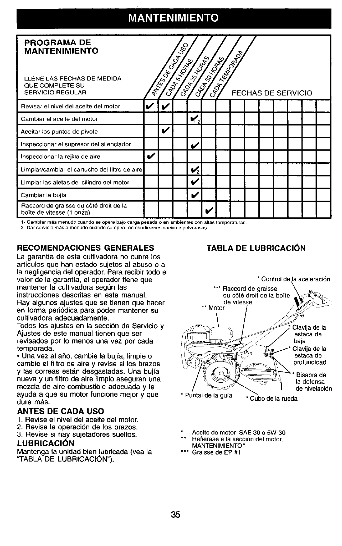
""°°"'"°' /3//
MANTENIMIENTO _ _/_/__/_'_'7@'_'/ ._
LLENE LAS FECHAS DE MEDIDA _,_ ,
QUE COMPLETE SU _.: < r/<)_'/__-/<
SERVIClO REGULAR /o_"f o_'//"o_ S DE SERVICIO
Revisar el nivel del aceite del motor I_
Cambiar el aceite del motor <_
Aceitar los puntos de pivote I_
Inspeccionar el supresor del silenciador V'
Inspeccionar la rejilla de aire V'
Limpiar/cambiar el cartucho del filtro de aire _2
Limpiar las aletas del cilindro del motor
Cambiar la bujia If
Raccord de graisse du cSte droit de la
boite de vitesse (1 on_:a) V'i
1- Cambiar m_s menudo cuando se opere balo carga pesada o en ambientes con aitas temperaturas
2- Dar sewicio m,'ls a rnenudo cuando se opere en condiciones sucias o polvorosas
RECOMENDACIONES GENERALES
La garantia de esta cultivadora no cubre los
articulos que han estado sujetos al abuso o a
la negligencia del operador. Para recibir todo el
valor de la garantia, el operador tiene que
mantener la cultivadora segun las
instrucciones descritas en este manual.
Hay algunos ajustes que se tienen que hacer
en forma peri_lica para poder mantener su
cultivadora adecuadamente.
Todos los ajustes en la secci6n de Servicio y
Ajustes de este manual tienen que ser
revisados por Io menos una vez por cada
temporada.
• Una vez al aho, cambie la bujia, limpie o
cambie el filtro de aire y revise si los brazos
y las correas est_,n desgastadas. Una bujia
nueva y un filtro de aire limpio aseguran una
mezcla de aire-combustible adecuada y le
ayuda a que su motor funcione mejor y que
dure mas.
ANTES DE CADA USO
1. Revise el nivel del aceite del motor.
2. Revise la operaci6n de los brazos.
3. Revise si hay sujetadores sueltos.
LUBRICAClON
Mantenga la unidad bien !ubricada (vea la
"TABLA DE LUBRICACION").
TABLA DE LUBRICACION
* Control de la aceleraci6n
*** Raccord de graisse
du c6te droit de
de vitesse
** Motor
,: Clavija de la
estaca de
baja
de la
estaca de
profundidad
* Puntal de la guia
ladefensa
de nivelacion
* Cubo de la rueda
Aceite de motor SAE 30 o 5W-30
** Refierase a la seccion del motor,
MANTENIMIENTO"
*** Graisse de EP #1
35
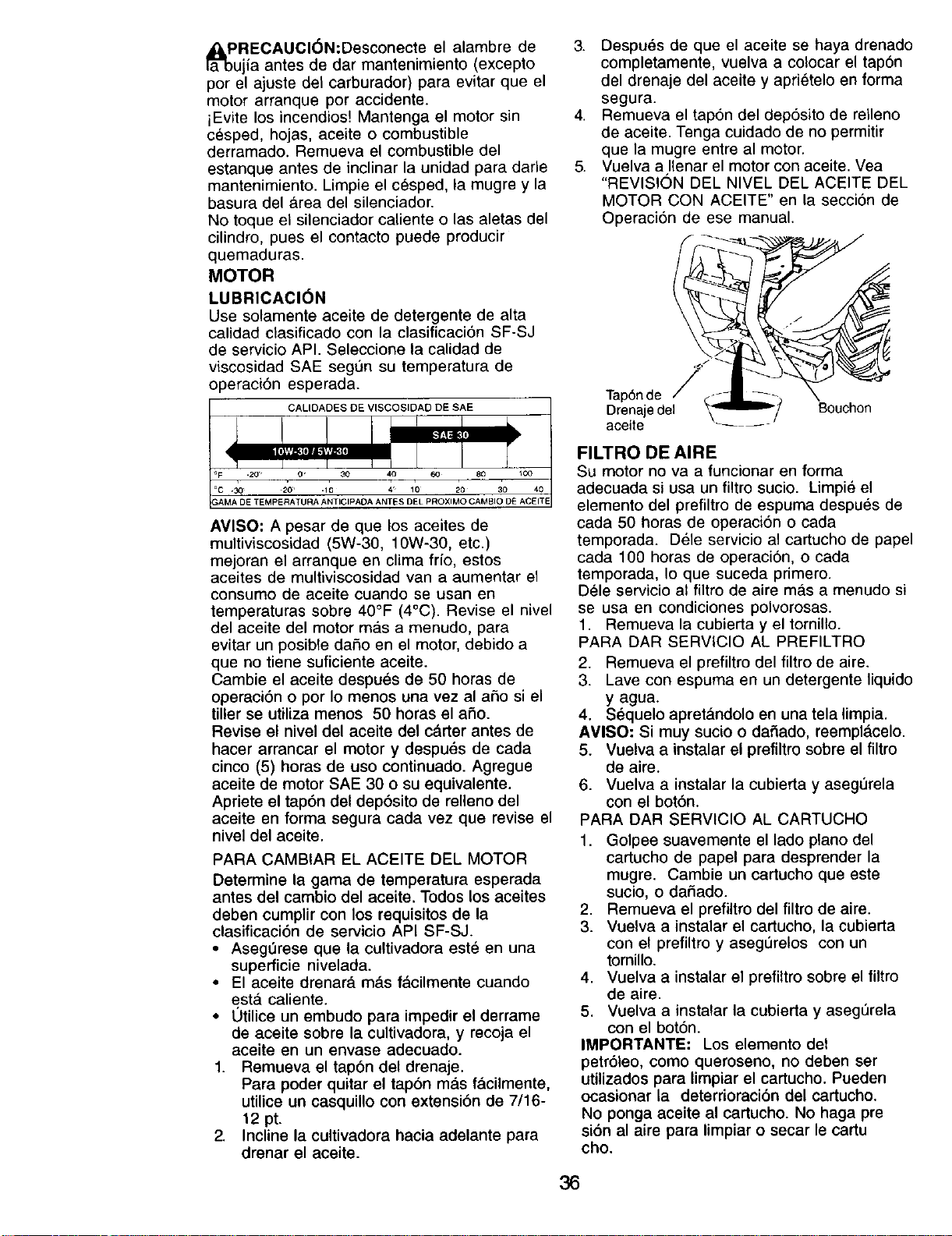
_lPRECAUCl6N:Desconecte el alambre de
ujia antes de dar mantenimiento (excepto
por el ajuste del carburador) para evitar que el
motor arranque pot accidente.
iEvite los incendios! Mantenga el motor sin
cesped, hojas, aceite o combustible
derramado. Remueva el combustible del
estanque antes de inclinar la unidad para darle
mantenimiento. Limpie el cesped, la mugre y la
basura del _,rea del silenciador.
No toque el silenciador caliente o las aletas del
cilindro, pues el contacto puede producir
quemaduras.
MOTOR
LUBRICACI6N
Use solamente aceite de detergente de alta
calidad clasificado con la clasificaciSn SF-SJ
de servicio API. Seleccione la calidad de
viscosidad SAE seg0n su temperatura de
operaci6n esperada.
CALIDADES DE VISCOSIDAD DE SAE
AMISO" A pesar de que los aceites de
multiviscosidad (5W-30, 10W-30, etc.)
mejoran el arranque en clima fib, estos
aceites de multiviscosidad van a aumentar el
consumo de aceite cuando se usan en
temperaturas sobre 40°F (4°C). Revise el nivel
del aceite del motor m_.s a menudo, para
evitar un posible dafio en el motor, debido a
que no tiene suficiente aceite.
Cambie el aceite despues de 50 horas de
operaciSn o por Io menos una vez al afio si el
tiller se utiliza menos 50 horas el afio.
Revise el nivel del aceite del cdrter antes de
hacer arrancar el motor y despu_s de cada
cinco (5) horas de uso continuado. Agregue
aceite de motor SAE 30 o su equivalente.
Apriete el tapSn del dep6sito de relleno del
aceite en forma segura cada vez que revise el
nivel del aceite.
PARA CAMBIAR EL ACEITE DEL MOTOR
Determine la gama de temperatura esperada
antes del cambio del aceite. Todos los aceites
deben cumpiir con los requisitos de la
clasificaciSn de servicio API SF-SJ.
• Asegerese que la cultivadora este en una
superficie nivelada.
• El aceite drenar_, m_.s facilmente cuando
esta. caliente.
• 0tilice un embudo para impedir el derrame
de aceite sobre la cultivadora, y recoja el
aceite en un envase adecuado.
1. Remueva el tap6n del drenaje.
Para poder quitar el tapdn mas f&cilmente,
utilice un casquillo con extensiSn de 7/16-
12 pt.
2. Incline la cultivadora hacia adelante para
drenar el aceite.
3. Despues de que el aceite se haya drenado
completamente, vuelva a colocar el tapon
del drenaje del aceite y aprietelo en forma
segura.
4. Remueva el tapon del depSsito de relleno
de aceite. Tenga cuidado de no permitir
que la mugre entre al motor.
5. Vuelva a Ilenar el motor con aceite. Yea
"REVISION DEL NIVEL DEL ACEITE DEL
MOTOR CON ACEITE" en la seccion de
Operacisn de ese manual.
Tap6n de
Drenaje del
aceite ....
Bouchon
FILTRO DE AIRE
Su motor no va a funcionar en forma
adecuada si usa un filtro sucio. Limpie el
elemento del prefiltro de espuma despu_s de
cada 50 horas de operaci6n o cada
temporada. Dele servicio al cartucho de papel
cada 100 horas de operaci6n, o cada
temporada, Io que suceda primero.
Dele servicio al filtro de aire ma.s a menudo si
se usa en condiciones polvorosas.
1. Remueva la cubierta y el tornillo.
PARA DAR SERVICIO AL PREFILTRO
2. Remueva el prefiltro del filtro de aire.
3. Lave con espuma en un detergente liquido
y agua.
4. S_quelo apretQndolo en una tela limpia.
AVISO: Si muy sucio o dafiado, reempldcelo.
5. Vuelva a instalar el prefiltro sobre el filtro
de aire.
6. Vuelva a instalar la cubierta y asegOrela
con el bot6n.
PARA DAR SERVICIO AL CARTUCHO
1. Golpee suavemente el lado piano del
cartucho de papel para desprender la
mugre. Cambie un cartucho que este
sucio, o dafiado.
2. Remueva el prefiltro del filtro de aire.
3. Vuelva a instalar el cartucho, la cubierta
con el prefiltro y asegurelos con un
tornillo.
4. Vuelva a instalar el prefiltro sobre el filtro
de aire.
5. Vuelva a instalar la cubierta y aseg0rela
con el bot6n.
IMPORTANTE: Los elemento del
petr61eo, como queroseno, no deben ser
utilizados para limpiar el cartucho. Pueden
ocasionar la deterrioraci6n del cartucho.
No ponga aceite al cartucho. No haga pre
si6n al aire para limpiar o secar le cartu
cho.
36
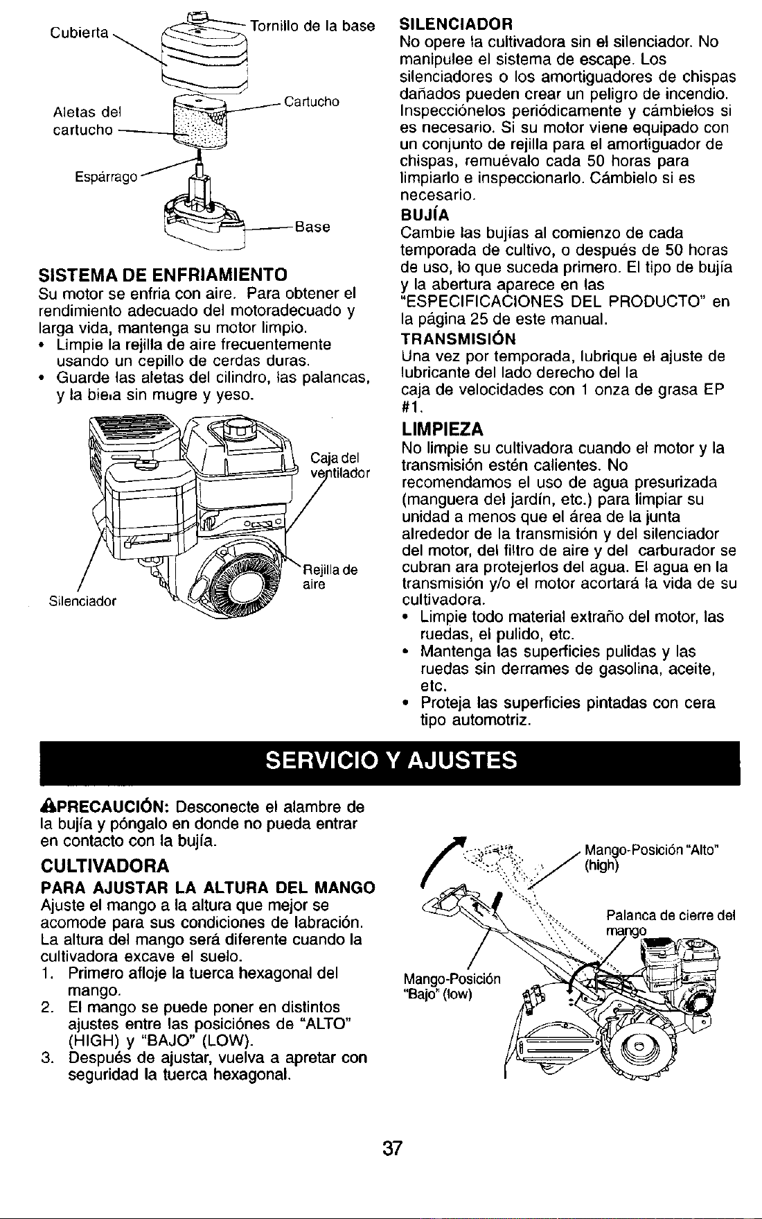
Cubierta
Aletas del
de la base
Cartucho
SISTEMA DE ENFRIAMIENTO
Su motor se enfria con aire. Para obtener el
rendimiento adecuado del motoradecuado y
larga vida, mantenga su motor limpio.
• Limpie la rejilla de aire frecuentemente
usando un cepillo de cerdas duras.
• Guarde las aletas del cilindro, las palancas,
y la bie,a sin mugre y yeso.
Caja del
Silenciador
ilia de
aire
SILENCIADOR
No opere la cultivadora sin e! silenciador. No
manipulee el sistema de escape. Los
silenciadores o los amortiguadores de chispas
daSados pueden crear un peligro de incendio.
Inspeccionelos peri6dicamente y c&mbielos si
es necesario. Si su motor viene equipado con
un conjunto de rejilla para el amortiguador de
chispas, remuevalo cada 50 horas para
limpiarlo e inspeccionarlo. Cambielo si es
necesario.
BUJ|A
Carnbie las bujias al comienzo de cada
temporada de cultivo, o despues de 50 horas
de uso, Io que suceda primero. El tipo de bujia
y la abertura aparece en las
"ESPECIFICACIONES DEL PRODUCTO" en
la pagina 25 de este manual.
TRANSMISI6N
Una vez por temporada, lubrique el ajuste de
lubricante del lado derecho della
caja de velocidades con 1 onza de grasa EP
#1.
LIMPIEZA
No limpie su cultivadora cuando el motor y la
transmisi6n esten calientes. No
recomendamos el uso de agua presurizada
(manguera del jardfn, etc.) para limpiar su
unidad a menos que el _rea de la junta
alrededor de la transmision y del silenciador
del motor, del filtro de aire y del carburador se
cubran ara protejerlos del agua. El agua en la
transmisi6n y/o el motor acortara la vida de su
cultivadora.
• Limpie todo material extraSo del motor, las
ruedas, el pulido, etc.
• Mantenga las superficies pulidas y las
ruedas sin derrames de gasolina, aceite,
etc.
• Proteja las superficies pintadas con cera
tipo automotriz.
_,PRECAUCl6N: Desconecte el alambre de
la bujia y pbngalo en donde no pueda entrar
en contacto con la bujfa.
CULTIVADORA
PARA AJUSTAR LA ALTURA DEL MANGO
Ajuste el mango a la altura que mejor se
acomode para sus condiciones de labraci6n.
La altura del mango sera. diferente cuando la
cultivadora excave el suelo.
1. Primero afloje la tuerca hexagonal del
mango.
2. El mango se puede porter en distintos
ajustes entre las posici6nes de "ALTO"
(HIGH) y "BAJO" (LOW).
3. Despu_s de ajustar, vuelva a apretar con
seguridad la tuerca hexagonal.
Mango-Posici6n
"Baio" (low)
(high)
Palanca de cierre del
37
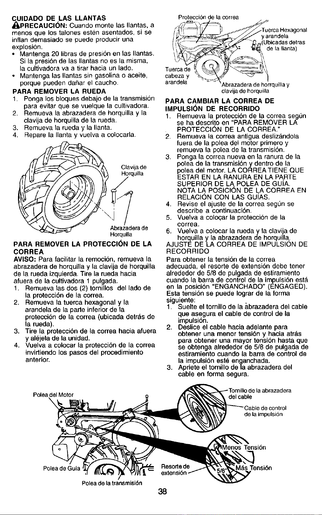
CUIDADO DE LAS LLANTAS
_i, PRECAUCI6N: Cuando monte las Ilantas, a
menos que los talones esten asentados, si se
inflan demasiado se puede producir una
explosi6n.
• Mantenga 20 libras de presi6n en las Ilantas.
Si la presi6n de las Ilantas no es la misma,
la cultivadora va a tirar hacia un lado.
• Mantenga las Ilantas sin gasolina o aceite,
porque pueden dafiar el caucho.
PARA REMOVER LA RUEDA
1. Ponga los bloques debajo de la transmision
para evitar que se vuelque la cultivadora.
2. Remueva la abrazadera de horquilla y la
clavija de horquitla de la rueda.
3. Remueva la rueda y la Ilanta.
4. Repare la Ilanta y vuelva a colocarla.
'_J _ _ Clavija de
i I ,F/
Abrr_z_,daerade
PARA REMOVER LA PROTECCI6N DE LA
CORREA
AVISO: Para facilitar la remoci6n, remueva la
abrazadera de horquilla y la clavija de horquilla
de la rueda izquierda. Tire la rueda hacia
afuera de la cultivadora 1 pulgada.
1. Remueva las dos (2) tornillos del lado de
la protecci6n de la correa.
2. Remueva la tuerca hexagonal y la
arandela de la parte inferior de la
protecci6n de la correa (ubicada detr&s de
la rueda).
3. Tire la protecci6n de la correa hacia afuera
y alejela de la unidad.
4. Vuelva a colocar la protecci6n de la correa
invirtiendo los pasos del procedimiento
anterior.
Proteccion de la correa
y arandela
Ubicadas detras
de la Ilanta)
Tuerca de
cabeza y
a_ndela
\brazadera de horrquilla y
clavija de horquilla
PARA CAMBIAR LA CORREA DE
IMPULSION DE RECORRIDO
1. Remueva la protecci6n de la correa segl_n
se ha descri,to en "PARA REMOVER LA
PROTECCION DE LA CORREA."
2. Remueva la correa antigua deslizandola
fuera de la polea del motor primero y
remueva la polea de la transmisi6n.
3. Ponga la correa nueva en la ranura de la
polea de la transmisi6n y dentro de la
polea del motor. LA CORREATIENE QUE
ESTAR EN LA RANURA EN LA PARTE
SUPERIOR DE LA POLEA DE GUIA.
NOTA LA POSIC!ON DE LA CORREA EN
RELAClON CON LAS GU[AS.
4. Revise el ajuste de la correa segun se
describe a continuaci6n.
5. Vuelva a colo(;:ar la protecci6n de la
correa.
6. Vuelva a colocar la rueda y la clavija de
horquilla y la abrazadera de horquilla;
AJUSTE DE LA CORREA DE IMPULSION DE
RECORRIDO
Para obtener la tension de la correa
adecuada, el resorte de extensi6n debe tener
alrededor de 5/8 de pulgada de estiramiento
cuando la barra de control de la impulsi6n esta
en la posici6n "ENGANCHADO" (ENGAGED).
Esta tensi6n se puede Iograr de la forma
siguiente:
1. Suelte el tornillo de la &brazadera del cable
que asegura el cable de control de la
impulsi6n.
2. Deslice el cable hacia adelante para
obtener una menor tensi6n y hacia atrds
para obtener una mayor tensi6n hasta que
se obtenga alrededor de 5/8 de pulgada de
estiramiento cuando la barra de control de
la impulsi6n este enganchada.
3. Apriete el tornillo de la abrazadera del
cable en forma segura.
Polea del Motor
X
del cable
de la impulsi6n
Tensi6n
Polea de Guia
Poleade la transmisi6n
38
MdsTensi6n
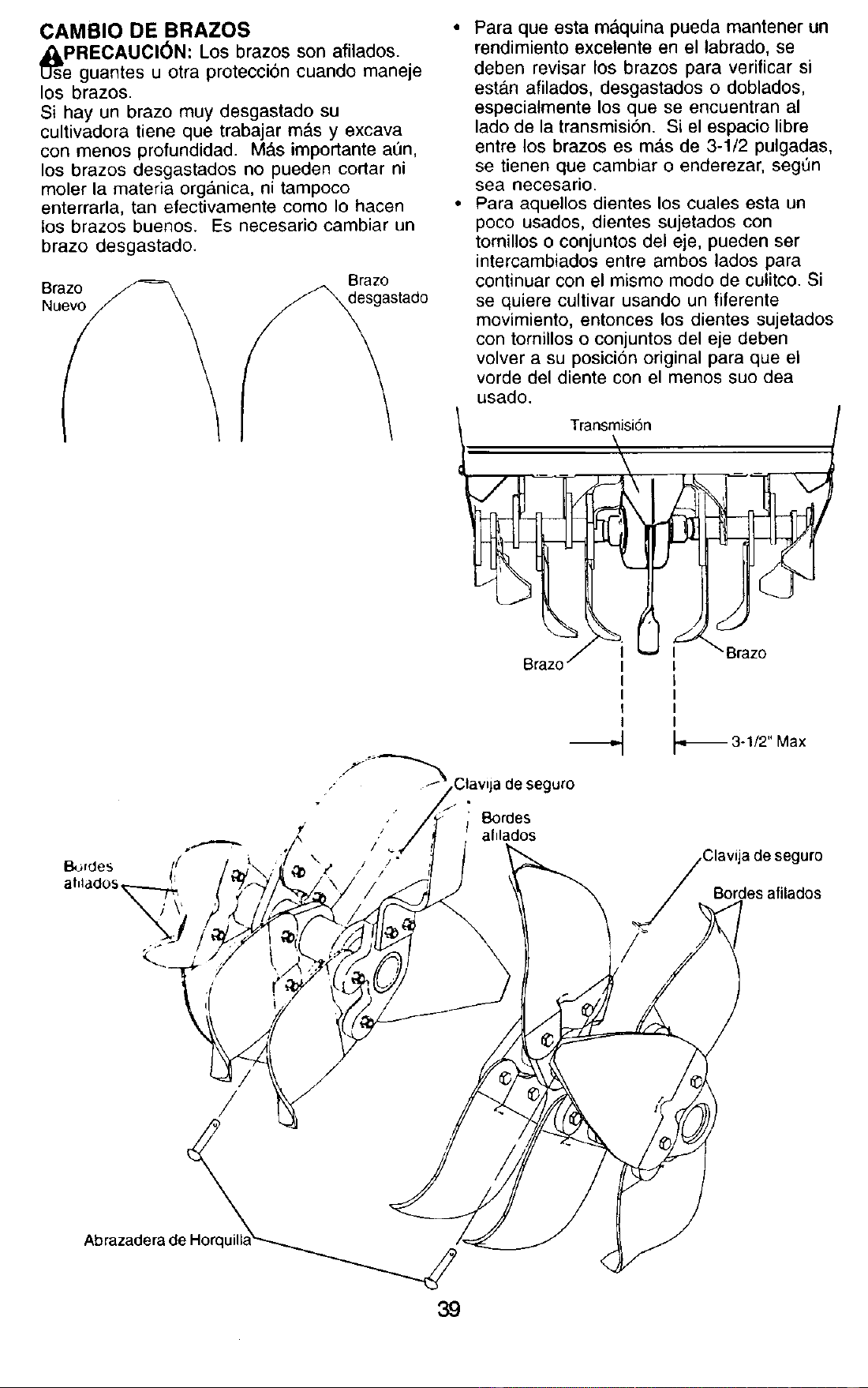
CAMBIO DE BRAZOS
_sePRECAUCI(_N: Los brazos son afilados.
guantes u otra protecci6n cuando maneje
los brazos.
Si hay un brazo muy desgastado su
cultivadora tiene que trabajar ma_sy excava
con menos profundidad. M&s importante at)n,
los brazos desgastados no pueden cortar ni
moler la materia org#,nica, ni tampoco
enterrarla, tan efectivamente como Io hacen
los brazos buenos. Es necesario cambiar un
brazo desgastado.
• Para que esta m_lquina pueda mantener un
rendimiento excelente en el labrado, se
deben revisar los brazos para verificar si
esta.n afilados, desgastados o doblados,
especiatmente los que se encuentran al
lado de la transmisi6n. Si el espacio libre
entre los brazos es ma,s de 3-1/2 pulgadas,
se tienen que cambiar o enderezar, segt]n
sea necesario.
• Para aquellos dientes los cuales esta un
poco usados, dientes sujetados con
tornillos o conjuntos del eje, pueden ser
intercambiados entre ambos lados para
continuar con el mismo modo de culitco. Si
se quiere cultivar usando un fiferente
movimiento, entonces los dientes sujetados
con tornillos o conjuntos del eje deben
volver a su posicion original para que el
vorde del diente con el menos suo dea
usado.
;_
I
I
I
I
---,-.I -*_ 3-1/2" Max
/
Bordes
afllados
Bordes alilados
/
Abrazadera de
39
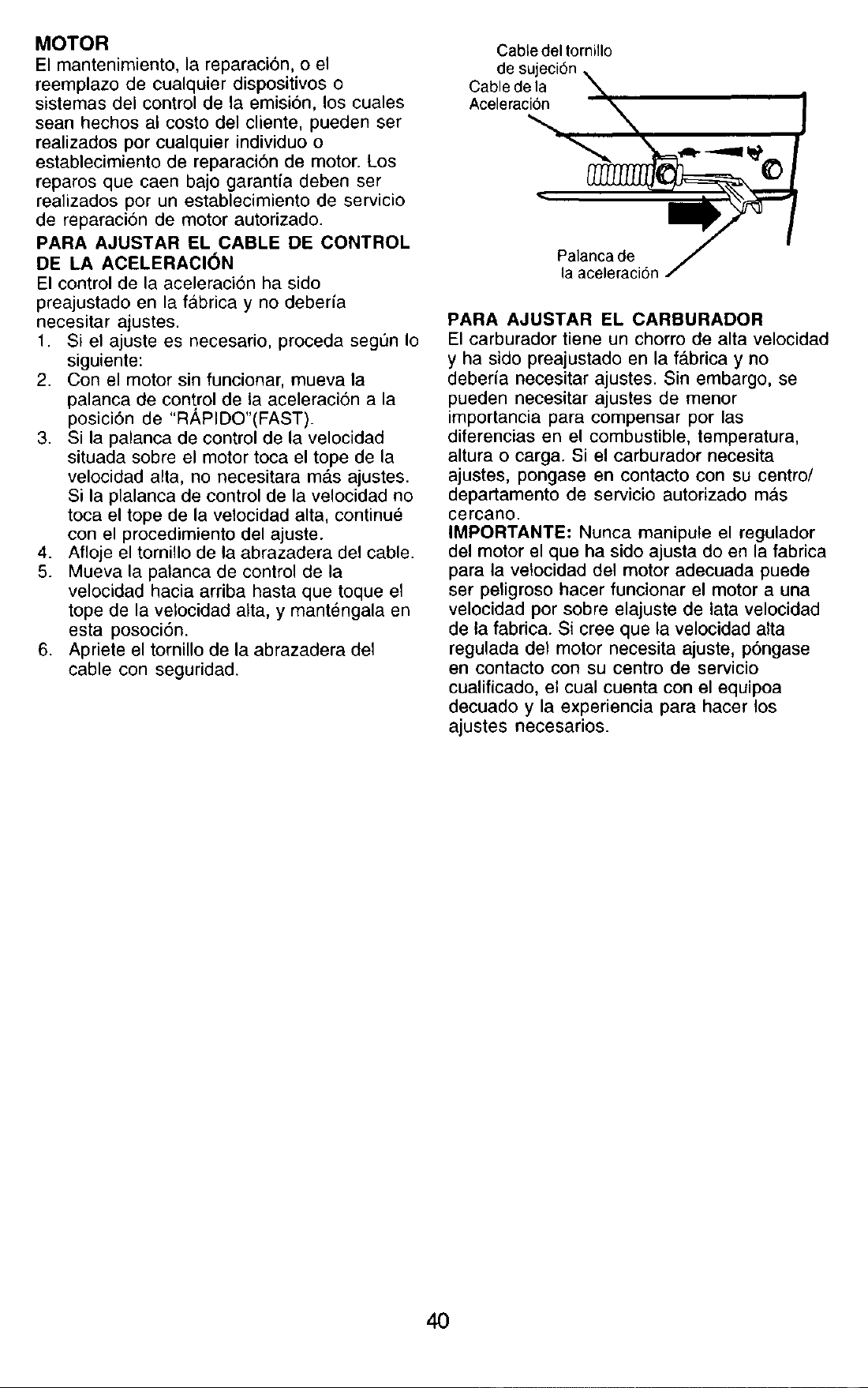
MOTOR
El mantenimiento, la reparaci6n, o el
reemplazo de cualquier dispositivos o
sistemas del control de la emision, los cuales
sean hechos at costo del cliente, pueden ser
realizados por cualquier individuo o
establecimiento de reparacion de motor. Los
reparos que caen bajo garantia deben ser
realizados por un establecimiento de servicio
de reparacion de motor autorizado.
PARA AJUSTAR EL CABLE DE CONTROL
DE LA ACELERACI(_N
El control de la aceleraci6n ha sido
preajustado en la fabrica y no deberia
necesitar ajustes.
1. Si el ajuste es necesario, proceda segun Io
siguiente:
2. Con el motor sin funcionar, mueva la
palanca de control de la aceleraci6n a la
posici6n de "R,i_PIDO"(FAST).
3. Si la palanca de control de la velocidad
situada sobre el motor toca el tope de la
velocidad alta, no necesitara m_s ajustes.
Si la plalanca de control de la velocidad no
toca el tope de la velocidad alta, continue
con el procedimiento del ajuste.
4. Afloje el tornillo de la abrazadera del cable.
5. Mueva la patanca de control de la
velocidad hacia arriba hasta que toque el
tope de la vetocidad alta, y mant_ngala en
esta posoci6n.
6. Apriete el tornillo de la abrazadera del
cable con seguridad.
CabLedel tornillo
de sujeci6n
Cable de la \
Acelerac_ --'_ 1
,a'agc,agec, /
PARA AJUSTAR EL CARBURADOR
El carburador tiene un chorro de alta velocidad
y ha sido preajustado en la fa.brica y no
deberia necesitar ajustes. Sin embargo, se
pueden necesitar ajustes de menor
importancia para compensar por las
diferencias en el combustible, temperatura,
altura o carga. Si el carburador necesita
ajustes, pongase en contacto con su centro/
departamento de servicio autorizado mas
cercano.
IMPORTANTE" Nunca manipule el regulador
del motor el que ha sido ajusta do en la fabrica
para la velocidad de1 motor adecuada puede
ser peligroso hacer funcionar el motor a una
velocidad por sobre elajuste de lata velocidad
de la fabrica. Si cree que la velocidad alta
regulada del motor necesita ajuste, p6ngase
en contacto con su centro de servicio
cualificado, el cual cuenta con el equipoa
decuado y la experiencia para hacer los
ajustes necesarios.
40
Inmediatamente prepare su cultivadora para
el almacenamiento al final de la temporada o
si la unidad no se va a usar por 30 dias o
m_.s.
,APRECAUCI(_N: Nunca almacene la
cultivadora con gasolina en el estanque
dentro de un edificio en donde los gases
pueden alcanzar una llama expuesta o una
chispa. Permita que el motor se enfrie antes
de almacenarlo en cualquier recinto privado.
CULTIVADORA
1. Limpie toda la cultivadora (yea
"LIMPIEZA" en la secci6n de
Mantenimiento en este manual).
2. Inspeccione y cambie las correas, si es
necesario (vea las instrucciones para el
cambio de la correa en la secci6n de
Servicio y Ajustes de este manual).
3. Lubriquela seg6n se muestra en la
secci6n de Mantenimiento en este
manual.
4. AsegQrese que todas las tuercas, pernos
y tornitlos esten apretados en forma
segur_. Inspeccione las partes movibles
para verificar si estan dafiadas, rotas o
desgastadas. Cambielas si es necesario.
5. Retoque todas las superficies pintadas
que est6n oxidadas o picadas; use una lija
suavemente antes de pintar.
MOTOR
SISTEMA BE COMBUSTIBLE
IMPORTANTE: Es importante evitar que se
formen dep6sitos de goma en partes
fundamentales del sistema de combustible
tales como el carburador, el filtro del combus-
tible, la manguera del combustible o en el
estanque durante el almacenamiento. La
experiencia tambien indica que los combus-
tibles mezclados con alcohol (conocido como
gasohol o que tienen etanol o metanol) "
pueden atraer humedad, Io que conduce a la
separaci6n de &cidos durante el
almacenamiento. La gasolina &cidica puede
dafiar el sistema de combustible de un motor
durante el periodo de almacenamiento.
1. Drene el estanque de combustible.
2. Haga arrancar el motor y dejelo funcionar
hasta que las Ifneas del combustible y el
carburador est_n vacios.
• Nunca use los productos para limpieza del
carburador o del motor en el estanque de
combustible pues se pueden producir
dafios permanentes.
• Use combustible nuevo la pr6xima
temporada.
AVISO: El estabilizador de combustible es una
alternativa aceptable para reducir a un minimo
la formaci6n de depositos de goma en el
combustible durante el periodo de
almacenamiento. Agregue estabilizador a la
gasolina en el estanque de combustible o en el
envase para el almacenamiento. Siempre siga
la proporcion de mezcla que se encuentra en
el envase det estabilizador. Haga funcionar el
motor por Io menos 10 minutos despues de
agregar el estabilizador, para permitir que este
Ilegue al carburador. No drene la gasolina del
estanque de gasolina y el carburador si se
est& usando estabilizador de combustible.
ACEITE DEL MOTOR
Drene el aceite (con el motor caliente) y
cambieto con aceite de motor limpio. (Vea
"MOTOR" en la secci6n de Mantenimiento de
este manual.)
CILINDRO(S)
1. Remueva la bujfa.
2. Vacie una onza de aceite a traves del
agujero de la bujia en el cilindro.
3. Tire el mango del arrancador, tentamente,
vadas veces para distribuir el aceite.
4. Cambie por una bujia nueva.
OTROS
• No guarde la gasolina de una temporada a
la otra.
• Cambie el envase de la gasolina si se
empieza a oxidar. La oxidacion y/o la mugre
en su gasolina producirdn problemas.
• Si es posible, guarde su unidad en un
recinto cerrado y cubrala para protegerla
contra el polvo y la mugre.
• Cubra su unidad con un forro protector
adecuado que no retenga la humedad. No
use plAstico. El pl&stico no puede respirar,
Io que permite la formaci6n de
condensaci6n, Io que producirA la oxidacion
de su unidad.
IMPORTANTE: Nunca cubra la cultivadora
mientras el motor y las areas de escape
todavia estan calientes.
41
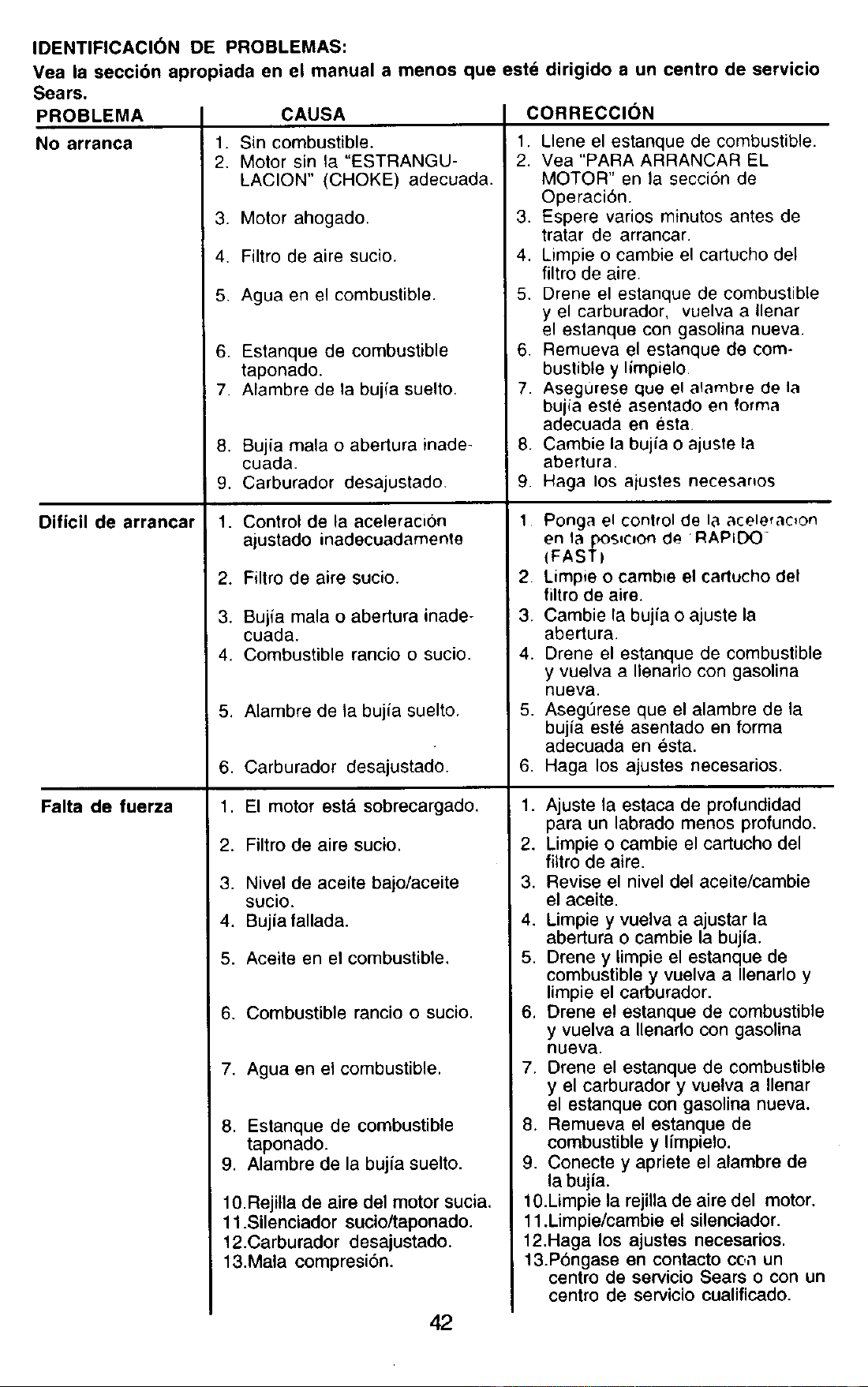
IDENTIFICACI6N DE PROBLEMAS:
Vea la seccibn apropiada en el manual a menos que estd dirigido a un centro de servicio
Sears.
PROBLEMA
1.
2.
CAUSA
Sin combustible.
Motor sin la "ESTRANGU-
LACION" (CHOKE) adecuada.
3. Motor ahogado.
4. Filtro de aire sucio.
5. Agua en el combustible.
6. Estanque de combustible
taponado.
7. Alambre de la bujia suelto
8. Bujia mala o abertura inade-
cuada.
9. Carburador desajustado
1. Control de la aceleraci6n
ajustado inadecuadamente
2. Filtro de aire sucio.
3. Bujia mala o abertura inade-
cuada.
4. Combustible rancio o sucio.
5. Alambre de la bujia suelto.
6. Carburador desajustado.
1. El motor esta sobrecargado.
2. Filtro de aire sucio.
3. Nivel de aceite bajo/aceite
sucio.
4. Bujia fallada.
5. Aceite en el combustible.
6. Combustible rancio o sucio.
No arranca
Dificil de arrancar
Falta de fuerza
7. Agua en el combustible.
8. Estanque de combustible
taponado.
9. Alambre de la bujia suelto.
10.Rejilla de aire del motor sucia.
11 .SUenciador sucio/taponado.
12.Carburador desajustado.
13.Mala comprasi6n.
CORRECCION
1. Llene el estanque de combustible.
2. Vea "PARA ARRANCAR EL
MOTOR" en la secci6n de
Operaci6n.
3. Espere varios minutos antes de
tratar de arrancar.
4. Limpie o cambie el cartucho del
filtro de aire.
5. Drene el estanque de combustible
y el carburador, vuelva a Ilenar
el estanque con gasolina nueva.
6 Remueva el estanque de com-
bustible y limpielo
7 Asegurese que el alambre de la
bujia esle asentado en forma
adecuada en esta.
8. Cambie la bujia o ajuste la
abertura
9 Haga los alustes necesa.os
1 Ponga el control de 18acelefacton
en la posse=Onde RAPID()
(FAST)
2. Limpie o cambia el cartucho del
filtro de aire.
3. Cambie la bujia o ajuste la
abertura.
4. Drene el estanque de combustible
y vuelva a nenarlo con gasolina
nueva.
5. Asegurese que el alambre de la
bujia este asentado en forma
adecuada en _sta.
6. Haga los ajustes necesarios.
1. Ajuste la estaca de profundidad
para un labrado menos profundo.
2. Limpie o cambie el cartucho del
_tro de aire.
3. Revise el nivel del aceite/cambie
el aceite.
4. Limpie y vuelva a ajustar la
abertura o cambie la bujia.
5. Drene y limpie el estanque de
combustible y vuelva a Ilenarlo y
limpie el carburador.
6. Drene el estanque de combustible
y vuelva a Ilenarlo con gasolina
nueva.
7. Drene el estanque de combustible
y el carburador y vuelva a Ilenar
el estanque con gasolina nueva.
8. Remueva el estanque de
combustible y limpielo.
9. Conecte y apriete el alambre de
la bujia.
10.Limpie la rejilla de aire del motor.
11 .Limpie/cambie el silenciador.
12.Haga los ajustes necesarios.
13.P6ngase en contacto cc,nun
centro de servicio Sears o con un
centro de servicio eualificado.
42
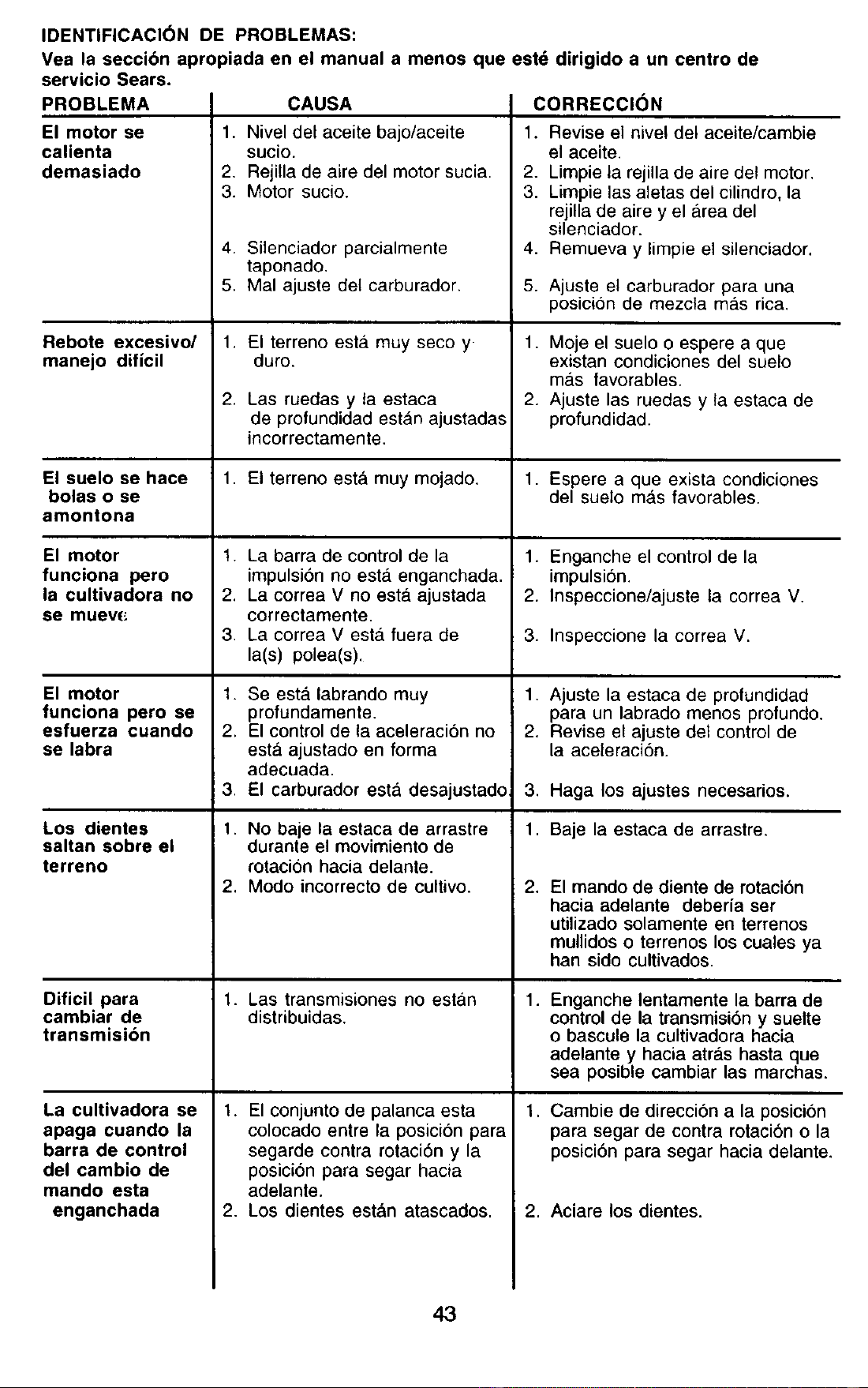
IDENTIFICACI6N DE PROBLEMAS:
Vea la seccibn apropiada en el manual a menos que estd dirigido a un centro de
servicio Sears.
PROBLEMA
El motor se
calienta
demasiado
Rebote excesivo/
manejo dificil
El suelo se hace
bolas o se
amontona
El motor
funciona pero
la cultivadora no
se muev(_
El motor
funciona pero se
esfuerza cuando
se labra
Los dientes
saltan sobre el
terreno
Dificil para
cambiar de
transmisibn
La cultivadora se
apaga cuando la
barra de control
del cambio de
mando esta
enganchada
CAUSA
1. Nivel del aceite bajo/aceite
sucio.
2. Rejilla de aire del motor sucia.
3. Motor sucio.
4. Silenciador parcialmente
taponado.
5. Mal ajuste del carburador.
.
• El terreno esta. muy seco y
duro.
Las ruedas y ta estaca
de profundidad estan ajustadas
incorrectamente.
• El terreno esta muy mojado.
1. La barra de control de la
impulsi6n no esta. enganchada.
2. La correa V no esta. ajustada
correctamente.
3. La correa V est,. fuera de
la(s) polea(s).
1.
2.
,
1.
,
Se esta labrando muy
profundamente.
El control de la aceleraci6n no
esta ajustado en forma
adecuada.
El carburador esta desajustado
No baje la estaca de arrastre
durante el movimiento de
rotacion hacia delante.
Modo incorrecto de cultivo.
1. Las transmisiones no estan
distribuidas.
1. El conjunto de palanca esta
colocado entre la posicion para
segarde contra rotaci6n y la
posici6n para segar hacia
adelante.
2. Los dientes est&n atascados.
CORRECCI(_N
1. Revise el nive! del aceite/cambie
el aceite.
2. Limpie la rejilla de aire del motor.
3. Limpie las aletas del cilindro, la
rejilla de aire y el area del
silenciador.
4. Remueva y limpie el silenciador.
5•
1.
2.
1.
•
2.
3.
Ajuste el carburador para una
posici6n de mezcla mas rica.
Moje el suelo o espere a que
existan condiciones del suelo
ma.s favorables.
Ajuste las ruedas y ta estaca de
profundidad.
Espere a que exista condiciones
del suelo ma,s favorables.
Enganche el control de la
impulsi6n.
Inspeccione/ajuste la correa V.
Inspeccione la correa V.
1. Ajuste la estaca de profundidad
para un labrado menos profundo.
2. Revise el ajuste del control de
la aceleraci6n.
,
1.
.
1.
,
Haga los ajustes necesarios.
Baje la estaca de arrastre.
El mando de diente de rotaci6n
hacia adelante debeda ser
utilizado solamente en terrenos
mullidos o terrenos los cuales ya
han sido cultivados.
Enganche lentamente la barra de
control de la transmisi6n y suelte
o bascule la cultivadora hacia
adelante y hacia atr&s hasta que
sea posible cambiar las marchas.
Cambie de direcci6n a la posici6n
para segar de contra rotaci6n o la
posicion para segar hacia delante.
2. Aciare los dientes.
43
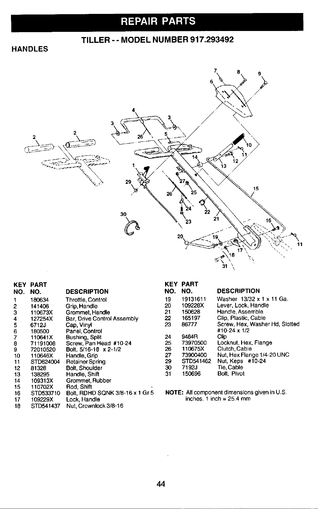
TILLER -- MODEL NUMBER 917.293492
HANDLES
2
7 8 9
/
4 .
23
15
31 \
\
11
KEY PART
NO. NO.
1 180634
2 141406
3 110673X
4 127254X
5 6712J
6 180500
7 110641X
8 71191008
9 72010520
10 110646X
11 STD624004
12 81328
13 138295
14 109313X
15 110702X
16 STD533710
17 1097_29X
18 STD541437
KEY PART
DESCRIPTION NO. NO. DESCRIPTION
Throttle, Control 19 19131611 Washer 13/32 x 1 x 11 Ga.
Grip,Handle 20 109228X Lever, Lock, Handle
Grommet, Handle 21 150628 Handle, Assemble
Bar, Drive Control Assembly 22 165197 Clip, Plastic, Cable
Cap, Vinyl 23 86777 Screw, Hex, Washer Hd, Slotted
Panel, Control #10-24 x 1/2
Bushing, Split 24 9484R Clip
Screw, Pan Head #10-24 25 73970500 Locknut, Hex, Flange
Bolt, 5/16-18 x 2-1/2 26 110675X Clutch,Cable
Handle, Grip 27 73900400 Nut, Hex Flange 1/4-20 UNC
RetainerSpring 29 STD541462 Nut, Keps #10-24
Bolt, Shoulder 30 7192J Tie, Cable
Handle, Shift 31 150696 Bolt, Pivot
Grommet, Rubber
Rod, Shift
Bolt, RDHD SQNK 3/8-16 x 1 Gr 5 NOTE: All component dimensions given in U.S.
Lock, Handle inches. 1 inch = 25.4 mm
Nut, Crownlock 3/8-16
44
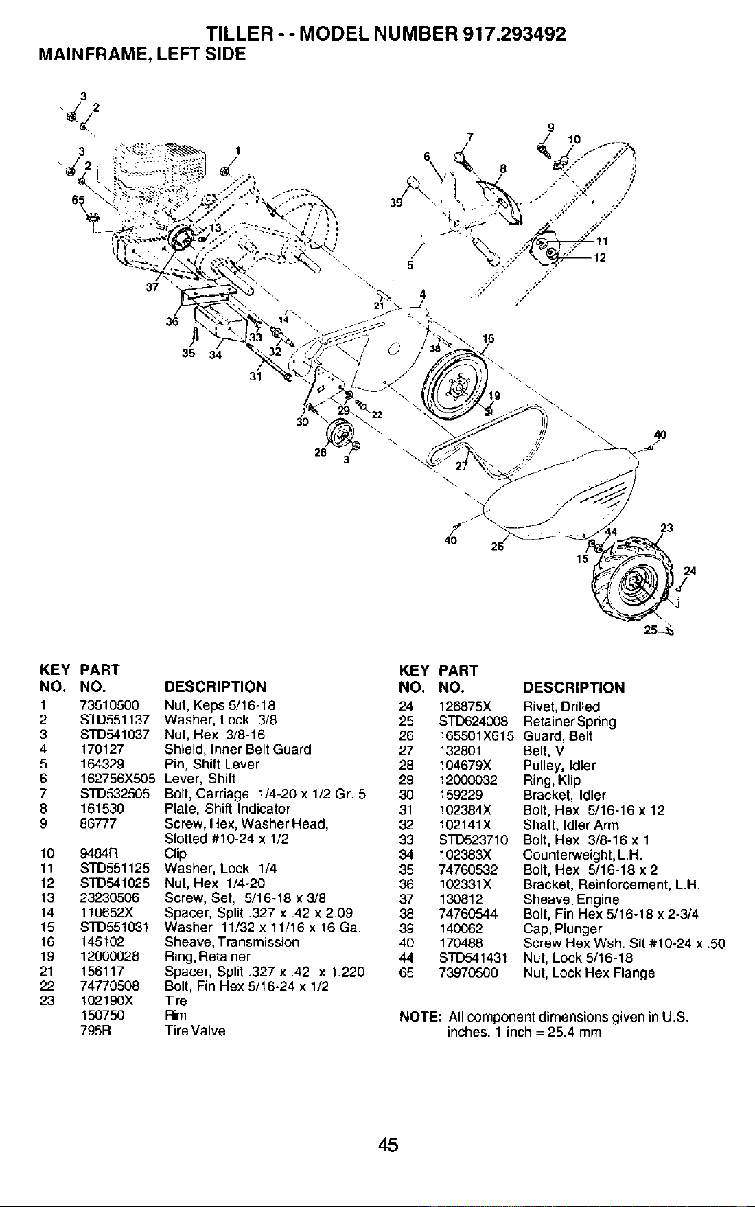
TILLER -- MODEL NUMBER 917.293492
MAINFRAME, LEFT SIDE
3
37
36
35
31
30
28
3
16
4O
4O
KEY PART
NO. NO.
1 73510500
2 STD551137
3 STD541037
4 170127
5 164329
6 162756X505
7 STD532505
8 161530
9 86777
10 9484R
11 STD551125
12 STD541025
13 23230506
14 110652X
15 STD551031
16 145102
19 12000028
21 156117
22 74770508
23 102190X
150750
795R
DESCRIPTION
Nut, Keps 5/16-18
Washer, Lock 3/8
Nut, Hex 3/8-16
Shield, Inner Belt Guard
Pin, Shift Lever
Lever, Shift
Bolt, Carriage 1/4-20 x 1/2 Gr. 5
Plate, Shift Indicator
Screw, Hex, Washer Head,
Slotted #10-24 x 1/2
Clip
Washer, Lock 1/4
Nut, Hex 1/4-20
Screw, Set, 5/16-18 x 3/8
Spacer, Split .327 x .42 x 2.09
Washer 11/32 x 11/16 x 16 Ga.
Sheave, Transmission
Ring, Retainer
Spacer, Split .327 x .42 x 1.220
Bolt, Fin Hex 5/16-24 x 1/2
Tire
Rim
Tire Valve
KEY PART
NO. NO. DESCRIPTION
24 126875X Rivet, Drilled
25 STD624008 Retainer Spring
26 t65501X615 Guard, Belt
27 132801 Belt, V
28 104679X Pulley, Idler
29 12000032 Ring, Klip
30 159229 Bracket, Idler
31 t02384X Bolt, Hex 5/16-16 x 12
32 102141X Shaft, Idler Arm
33 STD523710 Bolt, Hex 3/8-16 x 1
34 102383X Counterweight, L.H.
35 74760532 Bolt, Hex 5/16-18 x 2
36 102331X Bracket, Reinforcement, L.H.
37 130812 Sheave,Engine
38 74760544 Bolt, Fin Hex 5/16-18 x 2-3/4
39 140062 Cap, Plunger
40 170488 Screw Hex Wsh. Sit #10-24 x .50
44 STD541431 Nut, Lock 5/16-18
65 73970500 Nut, Lock Hex Flange
NOTE: All component dimensions given in U.S.
inches• 1 inch = 25.4 mm
45
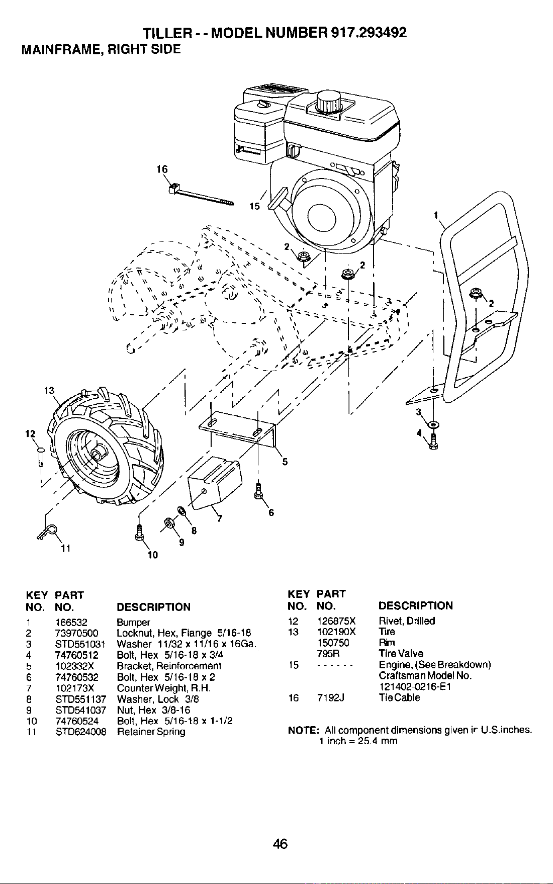
TILLER -- MODEL NUMBER 917.293492
MAINFRAME, RIGHT SIDE
16
12
13
5
I
t
/
8
9
10
/
! /
I,/
1
4\
KEY PART
NO. NO.
1 166532
2 73970500
3 STD551031
4 74760512
5 102332X
6 74760532
7 102173X
8 STD551137
9 STD541037
10 74760524
11 STD624008
DESCRIPTION
Bumper
Locknut, Hex, Flange 5/16-18
Washer 11/32 x 11/16 x 16Ga.
Bolt, Hex 5/16-18 x 3/4
Bracket, Reinforcement
Bolt, Hex 5/16-18 x 2
CounterWeight, RH.
Washer, Lock 3/8
Nut, Hex 3/8-16
Bolt, Hex 5/16-18 x 1-1/2
Retainer Spring
KEY PART
NO. NO. DESCRIPTION
12 126875X Rivet, Drilled
13 102190X Tire
150750
795R Tire Vatve
15 Engine, (See Breakdown)
Craftsman Model No.
121402-0216-E1
16 7192J TieCable
NOTE: All component dimensions given ir U.S.inches.
1 inch = 25.4 mm
46
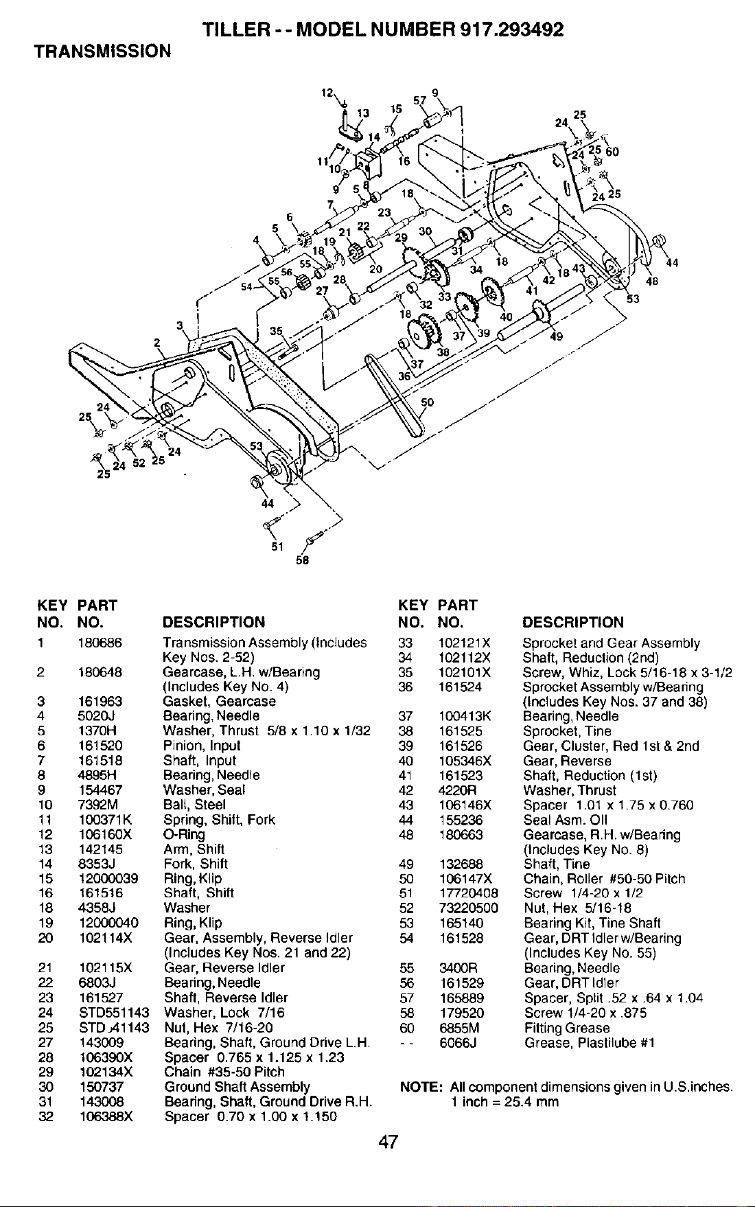
TILLER -- MODEL NUMBER 917.293492
TRANSMISSION
25
24_
2
48
53
KEY PART
NO. NO.
1 180686
2 180648
3 161963
4 5020J
5 1370H
6 161520
7 161518
8 4895H
9 154467
10 7392M
11 100371K
12 106160X
13 142145
14 8353J
15 12000039
16 161516
18 4358J
19 12000040
20 102114X
21 102115X
22 6803J
23 161527
24 STD551143
25 STD.;41143
27 143009
28 106390X
29 102134X
30 150737
31 143008
32 106388X
DESCRIPTION
KEY PART
NO. NO.
Transmission Assembly (Includes 33 102121X
Key Nos. 2-52) 34 102112X
Gearcase, L.H. w/Bearing 35 102101X
(Includes Key No. 4) 36 161524
Gasket, Gearcase
Bearing, Needle 37 100413K
Washer, Thrust 5/8 x 1.10 x 1/32 38 161525
Pinion, Input 39 161526
Shaft, Input 40 105346X
Bearing, Needle 41 161523
Washer, Seal 42 4220R
Ball, Steel 43 106146X
Spdng, Shift, Fork 44 155236
O-Ring 48 180663
Arm, Shift
Fork, Shift 49 132688
Ring, Klip 50 106147X
Shaft, Shift 51 17720408
Washer 52 73220500
Ring, Klip 53 165140
Gear, Assembly, Reverse Idler 54 161528
(Includes Key Nos. 21 and 22)
Gear, Reverse Idler 55 3400R
Bearing, Needle 56 161529
Shaft, Reverse Idler 57 165889
Washer, Lock 7/16 58 179520
Nut, Hex 7/16-20 60 6855M
Bearing, Shaft, Ground Drive L.H. - - 6066J
Spacer 0.765 x 1.125 x 1.23
Chain #35-50 Pitch
Ground Shaft Assembly
Beadng, Shaft, Ground Drive R.H
Spacer 0.70 x 1.00 x !.150
DESCRIPTION
Sprocket and Gear Assembly
Shaft, Reduction (2nd)
Screw, Whiz, Lock 5/16-18 x 3-1/2
Sprocket Assembly w/Bearing
(Includes Key Nos. 37 and 38)
Bearing, Needle
Sprocket, Tine
Gear, Cluster, Red 1st & 2nd
Gear, Reverse
Shaft, Reduction (1st)
Washer, Thrust
Spacer 1.01 x 1.75 x 0.760
Seal Asm. OII
Gearcase, R.H. w/Bearing
(Includes Key No. 8)
Shaft, Tine
Chain, Roller #50-50 Pitch
Screw 1/4-20 x 1/2
Nut, Hex 5/16-18
Bearing Kit, Tine Shaft
Gear, DRT Idler w/Bearing
(Includes Key No. 55)
Bearing, Needle
Gear, DRT Idler
Spacer, Split .52 x .64 x 1.04
Screw 1/4-20 x .875
Fitting Grease
Grease, Plastilube #1
NOTE: All component dimensions given in U.S.inches.
1 inch = 25.4 mm
47
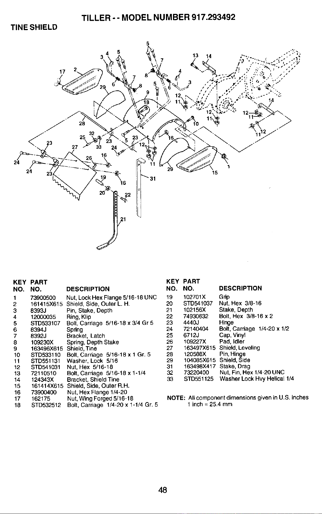
TINE SHIELD
TILLER -- MODEL NUMBER 917.293492
24
3
17
7
2
21
5
_31
1
29
15
J
KEY PART
NO. NO.
1 73900500
2 161415X615
3 8393J
4 12000035
5 STD533107
6 8394J
7 8392J
8 109230X
9 1634.96X615
10 STD533110
11 STD551131
12 STD541031
13 72110510
14 124343X
15 161414X615
16 73900400
17 162175
18 STD&32512
DESCRIPTION
Nut, Lock Hex Flange 5/16-18 UNC
Shield, Side, Outer L. H.
Pin, Stake, Depth
Ring, Klip
Bolt, Carriage 5/16-18 x 3/4 Gr 5
Spring
Bracket, Latch
Spring, Depth Stake
Shield, Tine
Bolt, Carriage 5/16-18 x 1 Gr. 5
Washer, Lock 5/16
Nut, Hex 5/16-18
Bolt, Carriage 5/16-18 x 1-1/4
Bracket, Shield Tine
Shield, Side, Outer R.H.
Nul, Hex Flange 1/4-20
Nut, Wing Forged 5/16-18
Bolt, Carriage 1/4-20 x 1-1/4 Gr. 5
KEY PART
NO. NO. DESCRIPTION
19 102701X Grip
20 STD541037 Nut, Hex 3/8-16
21 102156X Stake, Depth
22 74930632 Bolt, Hex 3/8-16 x 2
23 4440J Hinge
24 72140404 Bolt, Carriage 1/4-20 x 1/2
25 6712J Cap, Vinyl
26 109227X Pad, Idler
27 163497X615 Shield, Leveling
28 120588X Pin, Hinge
29 104085X615 Shield, Side
31 163498X417 Stake, Drag
32 73220400 Nut, Fin, Hex 1/4-20 UNC
33 STD551125 Washer Lock Hvy Hefical 1/4
NOTE: All component dimensions given in U.S. inches
1 inch = 25.4 mm
48
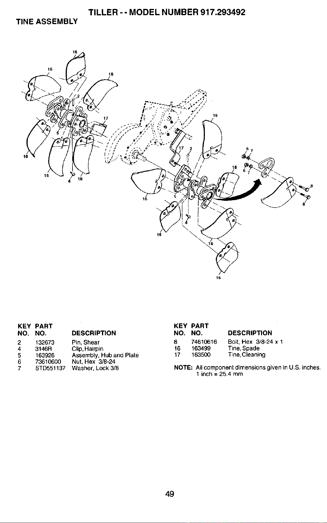
TILLER -- MODEL NUMBER 917.293492
TINE ASSEMBLY
16
16
16
16
\
4 16
16
16
16
KEY PART
NO. NO. DESCRIPTION
2
4
5
6
7
132673 Pin, Shear
3146R Clip, Hairpin
163926 Assembly, Hub and Plate
73610600 Nut, Hex 3/8-24
STD551137 Washer, Lock 3/8
KEY PART
NO. NO. DESCRIPTION
8 74610616 Bolt, Hex 3/8-24 x 1
16 163499 Tine, Spade
17 163500 Tine,Cleaning
NOTE: All component dimensions given in U.S. inches.
1 inch = 25.4 mm
49
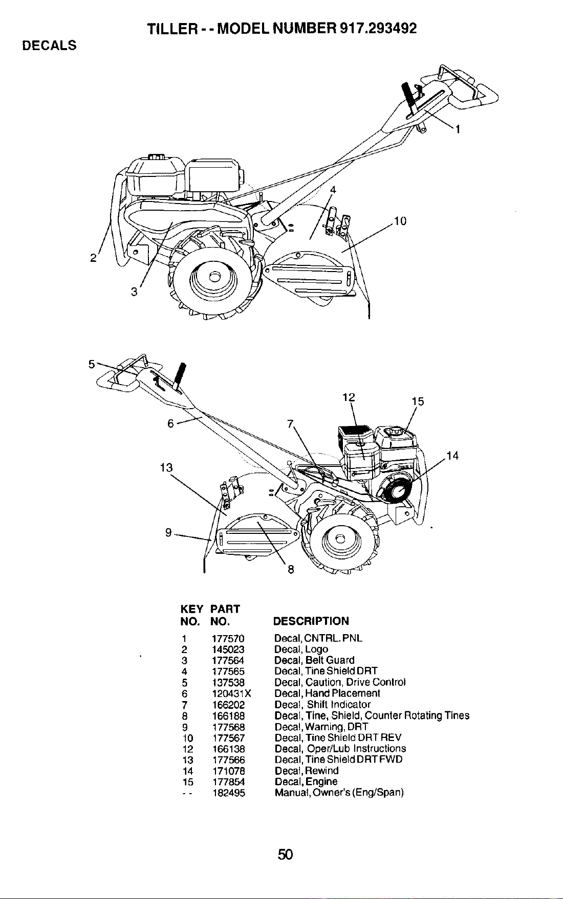
DECALS
TILLER -- MODEL NUMBER 917.293492
4
I 8
12
15
KEY PART
NO. NO.
1 177570
2 145023
3 177564
4 177565
5 137538
6 120431x
7 166202
8 166188
9 177568
to 177567
12 166138
13 177566
14 171078
15 177854
- - 182495
DESCRIPTION
Decal, CNTRL. PNL
Decal, Logo
Decal, Belt Guard
Decal, Tine Shield DRT
Decal, Caution, Drive Control
Decal, Hand Placement
Decal, Shift Indicator
Decal, "line, Shield, Counter Rotating Tines
Decal, Warning, DRT
Decal, Tine Shield DRT REV
Decal, Oper/Lub Instructions
Decal, Tine Shield DRT FWD
Decal, Rewind
Decal, Engine
Manuat, Owner's (Eng/Span)
50
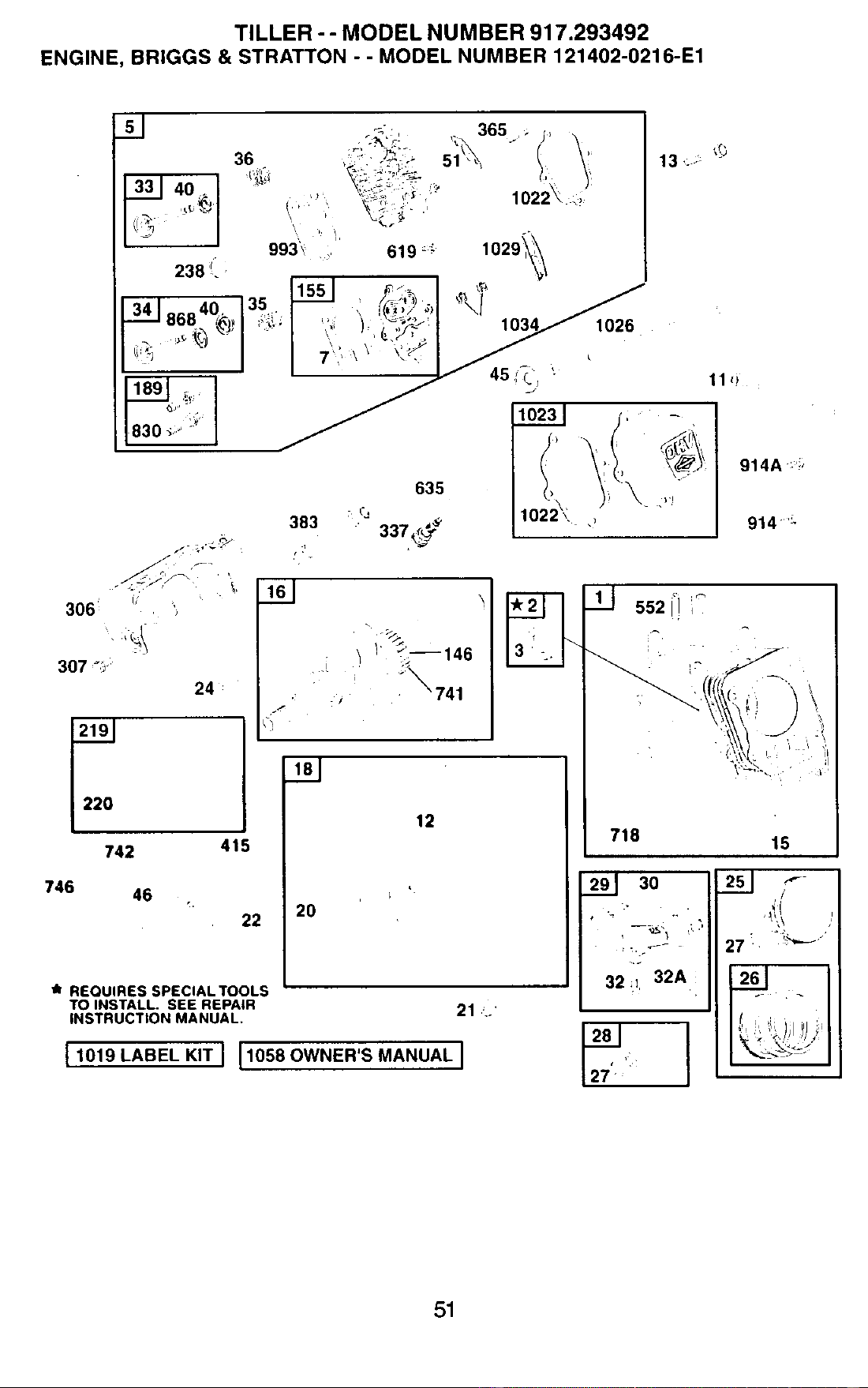
TILLER - - MODEL NUMBER 917.293492
ENGINE, BRIGGS & STRATTON - . MODEL NUMBER 121402-0216-E1
13 ,_.-:_'_
1026
306;
307_
742
746
46
383
)
24:
415
22 20
635
: Cj
! ; __-- 146
:;_741
12
/t REQUIRES SPECIAL TOOLS
TO INSTALL. SEE REPAIR
INSTRUCTION MANUAL, 21 =..
[_1019 LABEL KIT_ _058 OWNER'S MANUAL I
11 _)
51
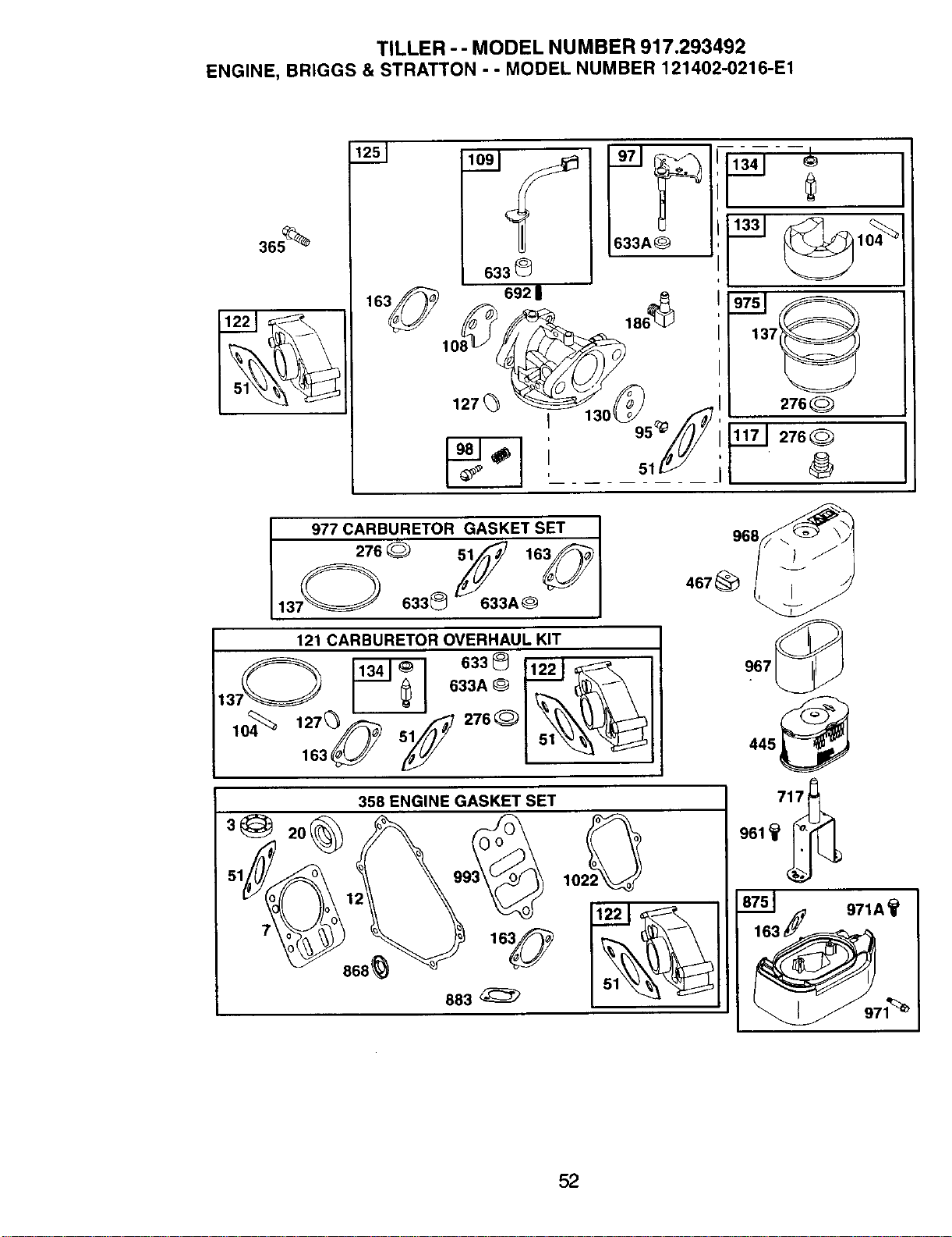
TILLER - - MODEL NUMBER 917.293492
ENGINE, BRIGGS & STRATTON - - MODEL NUMBER 121402-0216-E1
365_
I
977 CARBURETOR GASKET SET ]
6338 633A0 l
121 CARBURETOR OVERHAUL KIT
6338 11221
_--_ 633A® I_" _,_\
2O
358 ENGINE GASKET SET
883
967_
445 _
._ 971A_
52
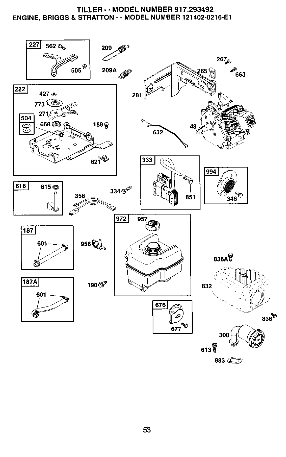
TILLER -- MODEL NUMBER 917.293492
ENGINE, BRIGGS & STRATTON - - MODEL NUMBER 121402-0216-E1
2271 562
2221 427
__668 _ 188
615_
187AI
334_
958
190_
281
632__ 48
836A_
836_
883
53
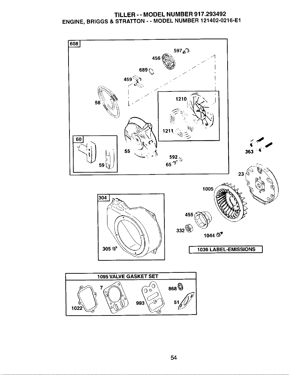
TILLER -- MODEL NUMBER 917.293492
ENGINE, BRIGGS & STRATTON - - MODEL NUMBER 121402-0216-E1
59
597_'_
456 _
689 _ /
459 "_ "/"
I
/
L /
J
/
/
1210 .,.]J. _\ ]
1211 _., I
.,,__,
363 4:
23
1005
I 1036 LABEL-EMISSIONS ]
1095 VALVE GASKET SET
54
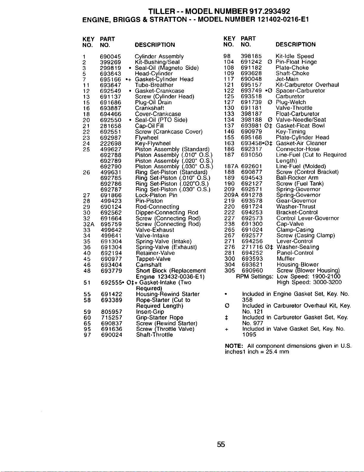
TILLER -- MODEL NUMBER 917.293492
ENGINE, BRIGGS & STRATTON - - MODEL NUMBER 121402-0216-E1
KEY PART KEY PART
NO, NO. DESCRIPTION NO. NO. DESCRIPTION
1 690045 Cylinder Assembly 98 398185 Kit-Idle Speed
2 399269 Kit-Bushing/Seal 104 691242 O Pin-Float Hinge
3 299819 • Seal-Oil (Magneto Side) 108 691182 Plate-Choke
5 693643 Head-Cylinder 109 693628 Shaft-Choke
7 695166 -+ Gasket-Cylinder Head 117 690048 Jet-Main
11 693647 Tube-Breather 121 695157 Kit-Carburetor Overhaul
12 692549 • Gasket-Crankcase 122 693749 •Q Spacer-Carburetor
13 691137 Screw (Cylinder Head) 125 693518 Carburetor
15 691686 Plug-Oil Drain 127 691739 G Plug-Welch
16 693887 Crankshaft 130 691181 Valve-Throttle
18 694466 Cover-Crankcase 133 398187 Float-Carburetor
20 692550 • Seal-Oil (PTO Side) 134 398188 O Valve-Needle/Seat
21 281658 Cap-OilFill 137 693981 Q:I: Gasket-Float Bowl
22 692551 Screw (Crankcase Cover) 146 690979 Key-Timing
23 692987 Flywheel 155 695168 Plate-Cylinder Head
24 222698 Key-Flywheel 163 693458•Q:1: Gasket-Air Cleaner
25 499627 Piston Assembly (Standard) 186 692317 Connector-Hose
692788 Piston Assembly (.010" O.S.) 187 691050 Line-Fuel (Cut to Required
692789 Piston Assembly (.020" O.S.) Length)
692790 Piston Assembly (.030" O.S.) 187A 692601 Line-Fuel (Molded)
26 499631 Ring Set-Piston (Standard) 188 690877 Screw (Control Bracket)
692785 Ring Set-Piston (.010" O.S.) 189 694543 Bali-Rocker Arm
692786 Ring Set-Piston (.020"O,S.) 190 692127 Screw (Fuel Tank)
692787 Ring Set-Piston (.030" O.S.) 209 692571 Spring-Governor
27 691866 Lock-Piston Pin 209A 691278 Spring-Governor
28 499423 Pin-Piston 219 693578 Gear-Governor
29 690124 Rod-Connecting 220 691724 Washer-Thrust
30 692562 Dipper-Connecting Rod 222 694253 Bracket-Control
32 691664 Screw (Connecting Rod) 227 692573 Control Lever-Governor
32A 695759 Screw (Connecting Rod) 238 691300 Cap-Valve
33 499642 Valve-Exhaust 265 691024 Clamp-Casing
34 499641 Valve-Intake 267 692577 Screw (Casing Clamp)
35 691304 Spring-Valve (Intake) 271 694256 Lever-Control
36 691304 Spring-Valve (Exhaust) 276 271716 G:I: Washer-Sealing
40 692194 Retainer-Valve 281 694252 Panel-Control
45 690977 Tappet-Valve 300 693593 Muffler
46 693404 Camshaft 304 693621 Housing-Blower
48 693779 Short Block (Replacement 305 690960 Screw (Blower Housing)
Engine 123432-0036-E1) RPM Settings: Low Speed: 1900-2100
51 692555• O,1:+Gasket-Intake (Two High Speed: 3000-3200
Required)
55 691422 Housing-Rewind Starter • Included in
58 693389 Rope-Starter (Cut to 358
Required Length) O Included in
59 805957 Insert-Grip No. 12t
60 715257 Grip-Starter Rope :1: Included in
65 690837 Screw (Rewind Starter) No. 977
95 691636 Screw (Throttle Valve) + Included in
97 690024 Shaft-Throttle 1095
Engine Gasket Set, Key. No.
Carburetor Overhaul Kit, Key.
Carburetor Gasket Set, Key.
Valve Gasket Set, Key. No.
NOTE: All component dimensions given in U.S.
inches1 inch = 25.4 mm
55
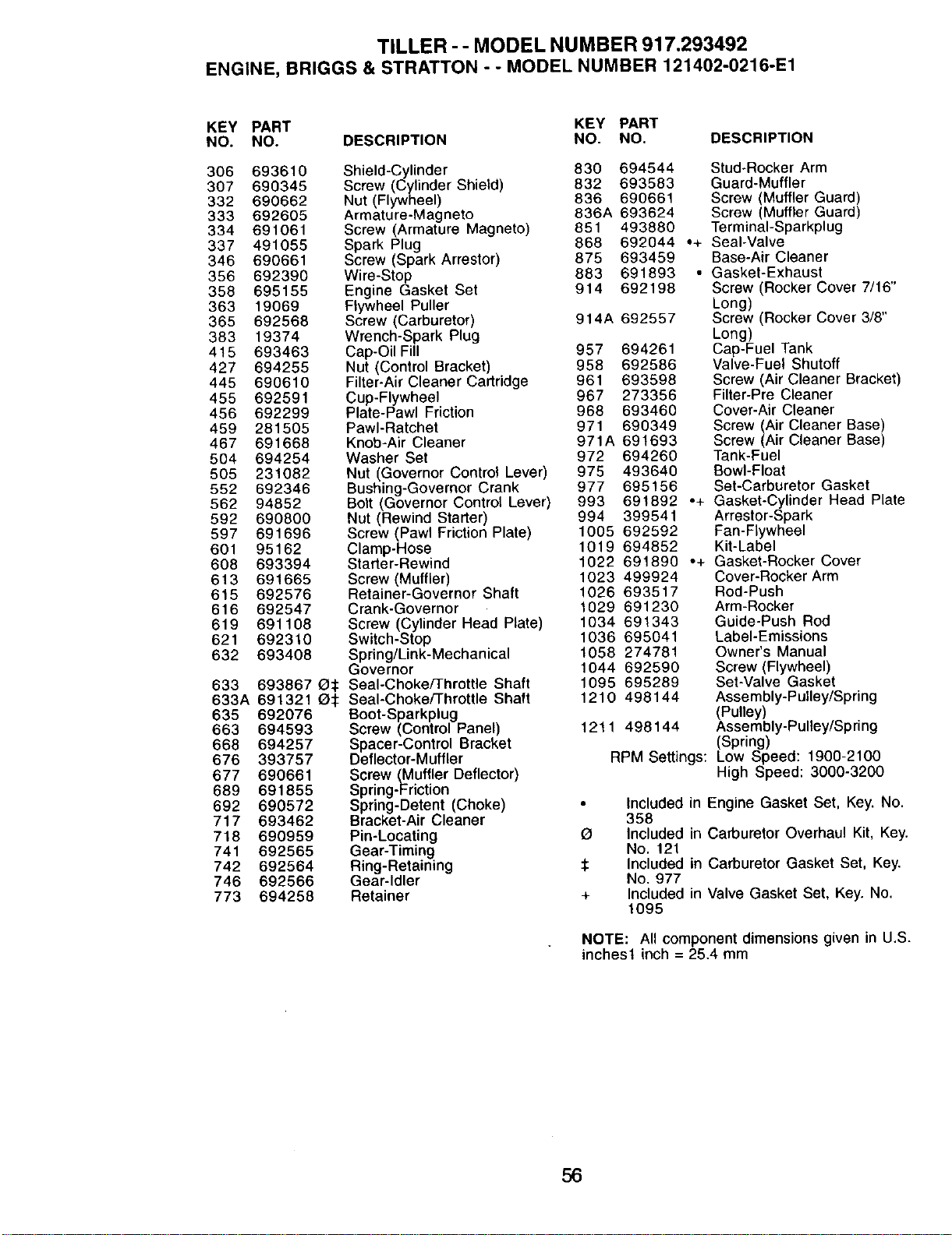
TILLER - - MODEL NUMBER 917,293492
ENGINE, BRIGGS & STRATTON - - MODEL NUMBER 121402-0216-E1
KEY PART KEY PART
NO. NO. DESCRIPTION NO. NO. DESCRIPTION
306 693610 Shield-Cylinder 830 694544
307 690345 Screw (Cylinder Shield) 832 693583
332 690662 Nut (Flywheel) 836 690661
333 692605 Armature-Magneto 836A 693624
334 691061 Screw (Armature Magneto) 851 493880
337 491055 Spark Plug 868 692044
346 690661 Screw (Spark Arrestor) 875 693459
356 692390 Wire-Stop 883 691893
358 695155 Engine Gasket Set 914 692198
363 19069 Flywheel Puller
365 692568 Screw (Carburetor) 914A 692557
383 19374 Wrench-Spark Plug
415 693463 Cap-Oil Fill 957 694261
427 694255 Nut (Control Bracket) 958 692586
445 690610 Filter-Air Cleaner Cartridge 961 693598
455 692591 Cup-Flywheel 967 273356
456 692299 Plate-Pawl Friction 968 693460
459 281505 PawI-Ratchet 971 690349
467 691668 Knob-Air Cleaner 971A 691693
504 694254 Washer Set 972 694260
505 231082 Nut (Governor Control Lever) 975 493640
552 692346 Bushing-Governor Crank 977 695156
562 94852 Bolt (Governor Control Lever) 993 691892 .+
592 690800 Nut (Rewind Starter) 994 399541
597 691696 Screw (Pawl Friction Plate) 1005 692592
601 95162 Clamp-Hose 1019 694852
608 693394 Starter-Rewind 1022 691890 -+
613 691665 Screw (Muffler) 1023 499924
615 692576 Retainer-Governor Shaft 1026 693517
616 692547 Crank-Governor 1029 691230
619 691108 Screw (Cylinder Head Plate) 1034 691343
621 692310 Switch-Stop 1036 695041
632 693408 Spring/Link-Mechanical 1058 274781
Governor 1044 692590
633 693867 Q:I: Seal-Choke/Throttle Shaft 1095 695289
633A 691321 _:1: Seal-Choke/Throttle Shaft 1210 498144
635 692076 Boot-Sparkplug
663 694593 Screw (Control Panel) 1211 498144
668 694257 Spacer-Control Bracket
676 393757 Deflector-Muffler
677 690661 Screw (Muffler Deflector)
689 691855 Spring-Friction
692 690572 Spring-Detent (Choke) •
717 693462 Bracket-Air Cleaner
718 690959 Pin-Locating O
741 692565 Gear-Timing
742 692564 Ring-Retaining :1:
746 692566 Gear-Idler
773 694258 Retainer +
Stud-Rocker Arm
Guard-Muffler
Screw (Muffler Guard)
Screw (Muffler Guard)
TerminaI-Sparkplug
•+ Seal-Valve
Base-Air Cleaner
• Gasket-Exhaust
Screw (Rocker Cover 7/16"
Long)
Screw (Rocker Cover 3/8"
Long)
Cap-Fuel Tank
Valve-Fuel Shutoff
Screw (Air Cleaner Bracket)
Filter-Pre Cleaner
Cover-Air Cleaner
Screw (Air Cleaner Base)
Screw (Air Cleaner Base)
Tank-Fuel
Bowl-Float
Set-Carburetor Gasket
Gasket-Cylinder Head Plate
Arrestor-Spark
Fan-Flywheel
Kit-Label
Gasket-Rocker Cover
Cover-Rocker Arm
Rod-Push
Arm-Rocker
Guide-Push Rod
Label-Emissions
Owner's Manual
Screw (Flywheel)
Set-Valve Gasket
Assembly-Pulley/Spring
(Pulley)
Assembly-Pulley/Spring
(Spring)
RPM Settings: Low Speed: 1900-2100
High Speed: 3000-3200
Included in Engine Gasket Set. Key. No.
358
Included in Carburetor Overhaul Kit, Key.
No. 121
Included in Carburetor Gasket Set, Key.
No. 977
Included in Valve Gasket Set, Key. No.
1095
NOTE: All component dimensions given in U.S.
inches1 inch = 25.4 mm
56

57

58


Get it fixed, at your home or ours!
For repair of major brand appliances in your own home...
no matter who made it, no matter who sold it!
1-800-4-MY-HOME _ AnyOne,dayorntght
(1-800-469-_r_3) (USA.andCanada)
www._rs.com wt,_N.sears.ca
For repair of carry-in products likevacuums, lawn equipment, and
electronics, call for the nearest Sears Parts and Repair Center.
1-800-488-1222 Any_me,dayorright(US.A.only)
w.se_'s.com
Forthe replacementpads, accessories and owner's manuals
that you need to do-it-yourself,call Sears PartsDirectS"!
1-800-366-PART 6a,m.-11 p.m., 7daysaweek
(1-800-3667278) (U.S.A. only)
www.sears.com/l_lsdirect
TO purchase or inquire about a Sears Service Agreement
or Sears Maintenance Agreement:
1-800-827-6655 (u.sA) 1-800-361-6665 (Canada)
7 a.m.- 5 p m., CST, Mort. - Sat 9 a.m.-8 p.m EST, M- F, 4 p.m. Sat
Para pe_r servic_oda reparad_ a
dom_io, y paraordenarpiezas:
1-888-SU-i..IOGARs_
(l-a_-7s4-6427)
Au Canada poursen,_ceenfran_s.
1-800.LE-FO_ER ic
(1-8oo-533.6937)
WWWsesrs.ca
© Sears,Roebud_andCo
HomeCentral®J
TM SM
® Registered Trademark / Trademark / Serv=ce Mark of Sears, Roebuck and Co
SM
® Mama Reg=strada/ Ta Marca de Fabnca / Mama de Servlclo de Sears, Roebuck and Co
MCMarque de commerce / MoMarque depos6e de Sears, Roebuck and Co
182495 1.11.02 TR Printed in U,S.A.