SE,IM $
OWNERS
MANUAL
MODEL NO.
919.184160
IMPORTANT:
Read the Safety Guidelines and
All Instructions Carefully Before
Operating.
CRAFTSMAN.
SINGLE STAGE
AIR COMPRESSOR
ASSEMBLY
OPERATION
MAINTENANCE
REPAIRPARTS
Record in the spaces provided.
(1) The model number which can be found
on the label on the front of the air tank
saddle.
(2) The code number which can be found
on the foil label on the side of the air
tank.
(3) The Manufacturer's Number (ASME
Code Compressors only) is located on
the metal data plate which is welded
onto the side of the air tank, (This data
plate is painted the same color as the
tank.)
(4) The Motor Manufacturer's name which
is located on the motor label.
(5) The Motor Mfg. number- also located
on the motor label.
Retain these numbers for future refer-
ence.
ModeINo.
Code No.
Sears, Roebuck and Co., Hoffman Estates, IL 60179 U.S.A.
D20410 Rev 0 2/16/00
Page
SAFETY GUIDELINES ........................................................................... 2
WARNING CHART ................................................................................. 3-5
SPECIFICATION CHART ...................................................................... 6
GLOSSARY ............................................................................................ 6
ACCESSORIES FOR USE WITH
SEARSAIR COMPRESSORS .......................................................... 6
GENERAL INFORMATION .................................................................... 7
DESCRIPTION OF OPERATION ........................................................... 7
INSTALLATION AND BREAK-IN PROCEDURES ................................. 7-9
LocationofAirCompressor .............................................................. 7
Piping............................................................................................... 8
Lubrication and Oil ........................................................................... 8
WiringInstructions............................................................................ 8
WiringDiagram ................................................................................. 8
Break-In Procedures......................................................................... 9
OPERATING PROCEDURES ................................................................. 9
MAINTENANCE ..................................................................................... 9-11
Air Compressor ................................................................................ 9
Air Filter - Inspection and Replacement ............................................ 9
Oil - Checking and Changing ............................................................ 10
Air Tank- Draining Water .................................................................. 10
Check Valve - Inspection and RepFacement ..................................... 10
Safety Valve Inspecti0n .................................................................... 10
Motor ................................................................................................ 10
Belt - Replacement .......................................................................... 10
Pulley and Flywheel -Alignment ....................................................... 11
TROUBLESHOOTING GUIDE ............................................................. 11-12
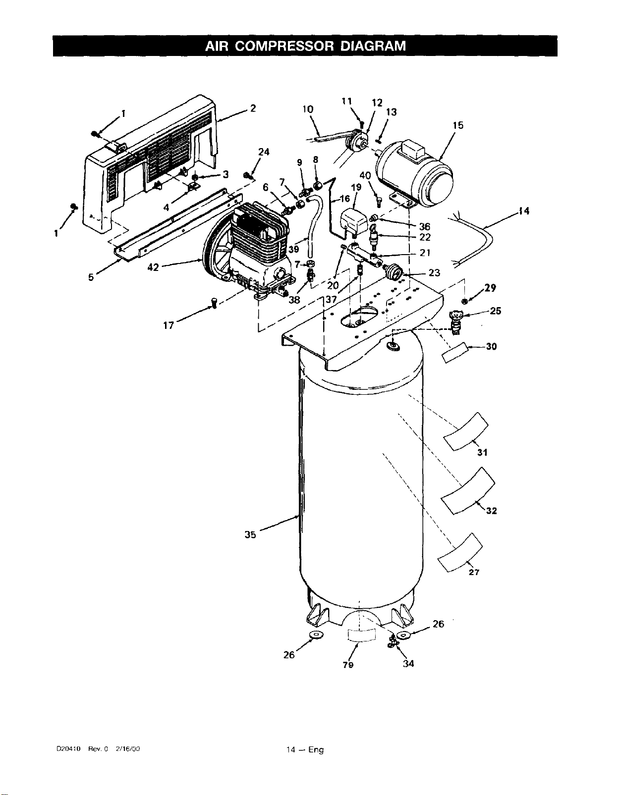
AIR COMPRESSOR DIAGRAM ............................................................. 14
Parts List .......................................................................................... 15
COMPRESSOR PUMP DIAGRAM ........................................................ 16
Parts List .......................................................................................... 17
HOW TO ORDER REPAIR PARTS ............................................. Back Cover
WARRANTY ............................................................................... BackCover
This manual contains information that is important for you to know and understand. This information relates to
protecting YOUR SAFETY and PREVENTING EQUIPMENT PROBLEMS. To help you recognize this information,
we use the symbols to the right. Please read the manual and pay attention to these sections.
DANG ERindicates an imminently hazardous situation
which, if not avoided, will result in death or serious
inLu__.
WARNING indicates a potentially hazardous situa*
tion which, if not avoided, could result in death of
serious injury.
CAUTION indicates a potentially hazardous situation
which, if not avoided, _ result in minor or rnoder-
CAUTION used without the safety alert symbol indi-
cates a potentially hazardous situation which, if not
avoided, _ result in property damage.
D20410 Rev 0 2/16/00 2 -- Eng
IMPROPER OPERATION OR MAINTENANCE OF THIS PRODUCT COULD RESULT tN SERIOUS INJURY AND PROPERTY
DAMAGE. READ AND UNDERSTAND ALL WARNINGS AND OPERATING INSTRUCTIONS BEFORE USING THIS EQUIPMENT.
SAVE THESE INSTRUCTIONS --
WHAT CAN HAPPEN
IT IS NORMAL FOR ELECTRICAL CONTACTS WITHIN THE
MOTOR AND PRESSURESWITCH TO SPARK.
IF ELECTRICAL SPARKS FROM COMPRESSOR COME INTO
CONTACT WITH FLAMMABLE VAPORS, THEY MAY IGNITE,
CAUSING FIRE OR EXPLOSION.
RESTRICTING ANY OF THE COMPRESSOR VENTILATION
OPENINGS WILL CAUSE SERIOUS OVERHEATING AND
COULD CAUSE FIRE.
UNATTENDED OPERATION OF THIS PRODUCT COULD
RESULT IN PERSONAL INJURY OR PROPERTY DAMAGE.
HOW TO PREVENT IT
ALWAYS OPERATE THE COMPRESSOR IN A WELL VENTI-
LATED AREA FREE OF COMBUSTIBLE MATERIALS,
GASOLINE OR SOLVENT VAPORS.
_F SPRAYING FLAMMABLE MATERIALS, LOCATE COMPRES-
SOR AT LEAST 20 FEET AWAY FROM SPRAY AREA. AN
ADDITIONAL LENGTH OF HOSE MAY BE REQUIRED.
STORE FLAMMABLE MATERIALS IN A SECURE LOCATION
AWAY FROM COMPRESSOR.
NEVER PLACE OBJECTS AGAINST OR ON TOP OF COM-
PRESSOR, OPERATE COMPRESSOR IN AN OPEN AREA AT
LEAST 12 INCHES AWAY FROM ANY WALL OR OBSTRUC-
TION THAT WOULD RESTRICT THE FLOW OF FRESH AIR TO
THE VENTILATION OPENINGS.
OPERATE COMPRESSOR IN A CLEAN, DRY, WELL VENTI-
LATED AREA. DO NOT OPERATE UNIT INDOORS OR IN ANY
CONFINED AREA.
ALWAYS REMAIN IN ATTENDANCE WITH THE PRODUCT
WHEN IT IS OPERATING.
.s,o,ou,s,.o
AIR TANK: THE FOLLOWING CONDITIONS COULD LEAD TO A WEAKENING OF THE TANK, AND RESULT IN A
VIOLENT TANK EXPLOSION AND COULD CAUSE PROPERTY DAMAGE OR SERIOUS INJURY.
WHAT CAN HAPPEN
1.FAILURE TO PROPERLY DRAIN CONDENSED WATER
FROM THE TANK, CAUSING RUST AND THINNING OF THE
STEEL TANK.
2 MODIFICATIONS OR ATTEMPTED REPAIRS TO THE TANK.
3. UNAUTHORIZED MODIFICATIONS TO THE UNLOADER
VALVE, SAFETY VALVE, OR ANY OTHER COMPONENTS
WHICH CONTROL TANK PRESSURE.
4 EXCESSIVE VIBRATION CAN WEAKEN THE AIR TANK
AND CAUSE RUPTURE OR EXPLOSION.
ATTACHMENTS & ACCESSORIES:
EXCEEDING THE PRESSURE RATING OF AIR TOOLS, SPRAY
GUNS, AIR OPERATED ACCESSORIES, TIRES AND OTHER
INFLATABLES CAN CAUSE THEM TO EXPLODE OR FLY
APART, AND COULD RESULTIN SERIOUSINJURY
HOW TO PREVENT IT
DRAIN TANK DALLY OR AFTER EACH USE, IF TANK DEVEL-
OPS A LEAK, REPLACE IT IMMEDIATELY WITH A NEW TANK OR
REPLACE THE ENTIRE COMPRESSOR.
NEVER DRILL INTO, WELD, OR MAKE ANY MODIFICATIONS
TO THE TANK OR ITS A_-ACHMENTS.
THE TANKIS DESIGNED TO WITHSTAND SPECIFIC OPERATING
PRESSURES, NEVER MAKE ADJUSTMENTS OR PARTS
SUBSTITUTIONS TO ALTER THE FACTORY SET OPERATING
PRESSURES.
FOR ESSENTIAL CONTROL OF AIR PRESSURE, YOU MUST
INSTALL A PRESSURE REGULATOR AND PRESSURE GAUGE
TO THE AIR OUTLET OF YOUR COMPRESSOR. FOLLOW THE
EQUIPMENT MANUFACTURERS RECOMMENDATION AND
NEVER EXCEED THE MAXIMUM ALLOWABLE PRESSURE
RATING OF ATrACHMENTS, NEVER USE COMPRESSOR TO
INFLATE SMALL LOW-PRESSURE OBJECTS SUCH AS
CHILDREN'S TOYS, FOOTBALLS, BASKETBALLS. ETC.
3 -- Eng D20410 Rev. 0 2/!6/00
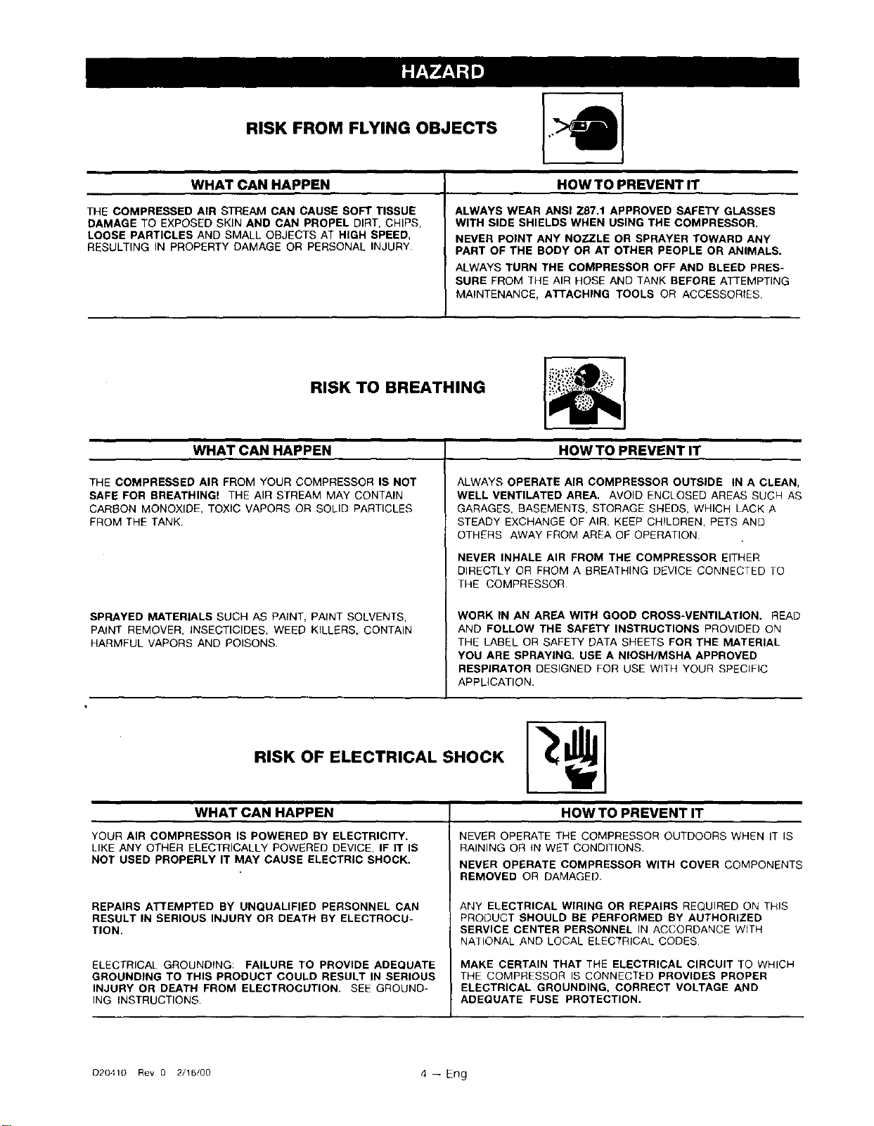
RISK FROM FLYING OBJECTS
WHAT CAN HAPPEN
THE COMPRESSED AIR STREAM CAN CAUSE SOFT TISSUE
DAMAGE TO EXPOSED SKIN AND CAN PROPEL DIRT, CHIPS,
LOOSE PARTICLES AND SMALL OBJECTS AT HIGH SPEED,
RESULTING IN PROPERTY DAMAGE OR PERSONAL INJURY
HOWTO PREVENTIT
ALWAYS WEAR ANSI Z87.1 APPROVED SAFETY GLASSES
WITH SIDE SHIELDS WHEN USING THE COMPRESSOR.
NEVER POINT ANY NOZZLE OR SPRAYER TOWARD ANY
PART OF THE BODY OR AT OTHER PEOPLE OR ANIMALS.
ALWAYS TURN THE COMPRESSOR OFF AND BLEED PRES-
SURE FROM THE AIR HOSE AND TANK BEFORE ATTEMPTING
MAINTENANCE, ATTACHING TOOLS OR ACCESSORIES
WHAT CAN HAPPEN
RISK TO BREATHING
THE COMPRESSED AIR FROM YOUR COMPRESSOR IS NOT
SAFE FOR BREATHING! THE AIR STREAM MAY CONTAIN
CARSON MONOXIDE, TOXIC VAPORS OR SOLID PARTICLES
FROM THE TANK.
SPRAYED MATERIALS SUCH AS PAtNT, PAINT SOLVENTS,
PAINT REMOVER, INSECTICIDES, WEED KILLERS, CONTAIN
HARMFUL VAPORS AND POISONS.
HOW TO PREVENT IT
ALWAYS OPERATE AIR COMPRESSOR OUTSIDE IN A CLEAN,
WELL VENTILATED AREA. AVOID ENCLOSED AREAS SUCH AS
GARAGES, BASEMENTS, STORAGE SHEDS, WHICH LACK A
STEADY EXCHANGE OF AIR. KEEP CHILDREN, PETS AND
OTHERS AWAY FROM AREA OF OPERATION
NEVER INHALE AIR FROM THE COMPRESSOR EITHER
DIRECTLY OR FROM A BREATHING DEVICE CONNECTED TO
THE COMPRESSOR
WORK IN AN AREA WITH GOOD CROSS-VENTILATION. READ
AND FOLLOW THE SAFETY INSTRUCTIONS PROVIDED ON
THE LABEL OR SAFETY DATA SHEETS FOR THE MATERIAL
YOU ARE SPRAYING. USE A NIOSH/MSHA APPROVED
RESPIRATOR DESIGNED FOR USE WITH YOUR SPECIFIC
APPLICATION.
WHATCANHAPPEN
YOUR AIR COMPRESSOR IS POWERED BY ELECTRICITY.
LIKE ANY OTHER ELECTRICALLY POWERED DEVICE, IF IT IS
NOT USED PROPERLY IT MAY CAUSE ELECTRIC SHOCK.
REPAIRS ATTEMPTED BY UNQUALIFIED PERSONNEL CAN
RESULT IN SERIOUS INJURY OR DEATH BY ELECTROCU-
TION.
ELECTRICAL GROUNDING: FAILURE TO PROVIDE ADEQUATE
GROUNDING TO THIS PRODUCT COULD RESULT IN SERIOUS
INJURY OR DEATH FROM ELECTROCUTION. SEE GROUND-
ING INSTRUCTIONS
HOWTO PREVENTIT
NEVER OPERATE THE COMPRESSOR OUTDOORS WHEN IT IS
RAINING OR IN WET CONDITIONS.
NEVER OPERATE COMPRESSOR WITH COVER COMPONENTS
REMOVED OR DAMAGED,
ANY ELECTRICAL WIRING OR REPAIRS REQUIRED ON THIS
PRODUCT SHOULD BE PERFORMED BY AUTHORIZED
SERVICE CENTER PERSONNEL IN ACCORDANCE WITH
NATIONAL AND LOCAL ELECTRICAL CODES
MAKE CERTAIN THAT THE ELECTRICAL CIRCUIT TO WHICH
THE COMPRESSOR IS CONNECTED PROVIDES PROPER
ELECTRICAL GROUNDING, CORRECT VOLTAGE AND
ADEQUATE FUSE PROTECTION.
D20410 Rev 0 2/16/00 4 -- Er)g
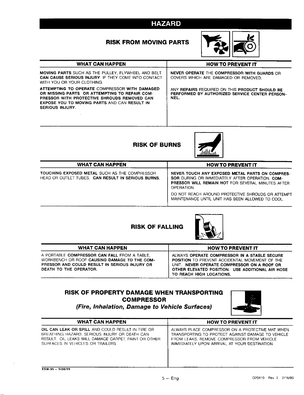
RISK FROM MOVING PARTS
WHAT CAN HAPPEN
MOVING PARTS SUCH AS THE PULLEY, FLYWHEEL AND BELT
CAN CAUSE SERIOUS INJURY IF THEY COME INTO CONTACT
WITH YOU OR YOUR CLOTHING,
ATTEMPTING TO OPERATE COMPRESSOR WITH DAMAGED
OR MISSING PARTS OR ATTEMPTING TO REPAIR COM-
PRESSOR WITH PROTECTIVE SHROUDS REMOVED CAN
EXPOSE YOU TO MOVING PARTS AND CAN RESULT IN
SERIOUS INJURY.
HOW TO PREVENT IT
NEVER OPERATE THE COMPRESSOR WITH GUARDS OR
COVERS WHICH ARE DAMAGED OR REMOVED,
ANY REPAIRS REQUIRED ON THIS PRODUCT SHOULD BE
PERFORMED BY AUTHORIZED SERVICE CENTER PERSON-
NEL.
RISK OF BURNS
WHAT CAN HAPPEN
TOUCHING EXPOSED METAL SUCH AS THE COMPRESSOR
HEAD OR OUTLETTUBES, CAN RESULT IN SERIOUS BURNS,
HOW TO PREVENT IT
NEVER TOUCH ANY EXPOSED METAL PARTS ON COMPRES-
SOR DURING OR IMMEDIATELY AFTER OPERATION. COM-
PRESSOR WILL REMAIN HOT FOR SEVERAL MINUTES AFTER
OPERATION.
DO NOT REACH AROUND PROTECTIVE SHROUDS OR A]-FEMPT
MAINTENANCE UNTIL UNIT HAS BEEN ALLOWED TO COOL.
RISK OF FALLING
WHAT CAN HAPPEN
A PORTABLE COMPRESSOR CAN FALL FROM A TABLE,
WORKBENCH OR ROOF CAUSING DAMAGE TO THE COM-
PRESSOR AND COULD RESULT IN SERIOUS INJURY OR
DEATH TO THE OPERATOR,
HOWTO PREVENT IT
ALWAYS OPERATE COMPRESSOR IN A STABLE SECURE
POSITION TO PREVENT ACCIDENTAL MOVEMENT OF THE
UNIT. NEVER OPERATE COMPRESSOR ON A ROOF OR
OTHER ELEVATED POSITION. USE ADDITIONAL AIR HOSE
TO REACH HIGH LOCATIONS.
RISK OF PROPERTY DAMAGE WHEN TRANSPORTING
COMPRESSOR
(Fire, Inhalation, Damage to Vehicle Surfaces)
WHATCANHAPPEN
OIL CAN LEAK OR SPILL AND COULD RESULT IN FIRE OR
BREATHING HAZARD, SERIOUS INJURY OR DEATH CAN
RESULT. OIL LEAKS WILL DAMAGE CARPET, PAINT OR OTHER
SURFACES rN VEHICLES OR TRAILERS
HOW TO PREVENT IT
ALWAYS PLACE COMPRESSOR ON A PROTECTIVE MAT WHEN
TRANSPORTING TO PROTECT AGAINST DAMAGE TO VEHICLE
FROM LEAKS. REMOVE COMPRESSOR FROM VEHICLE
IMMEDIATELY UPON ARRIVAL AT YOUR DESTINATION.
ESW-99 -- 9/26/99
5 -- Eng D20410 Rev 0 2/16/00
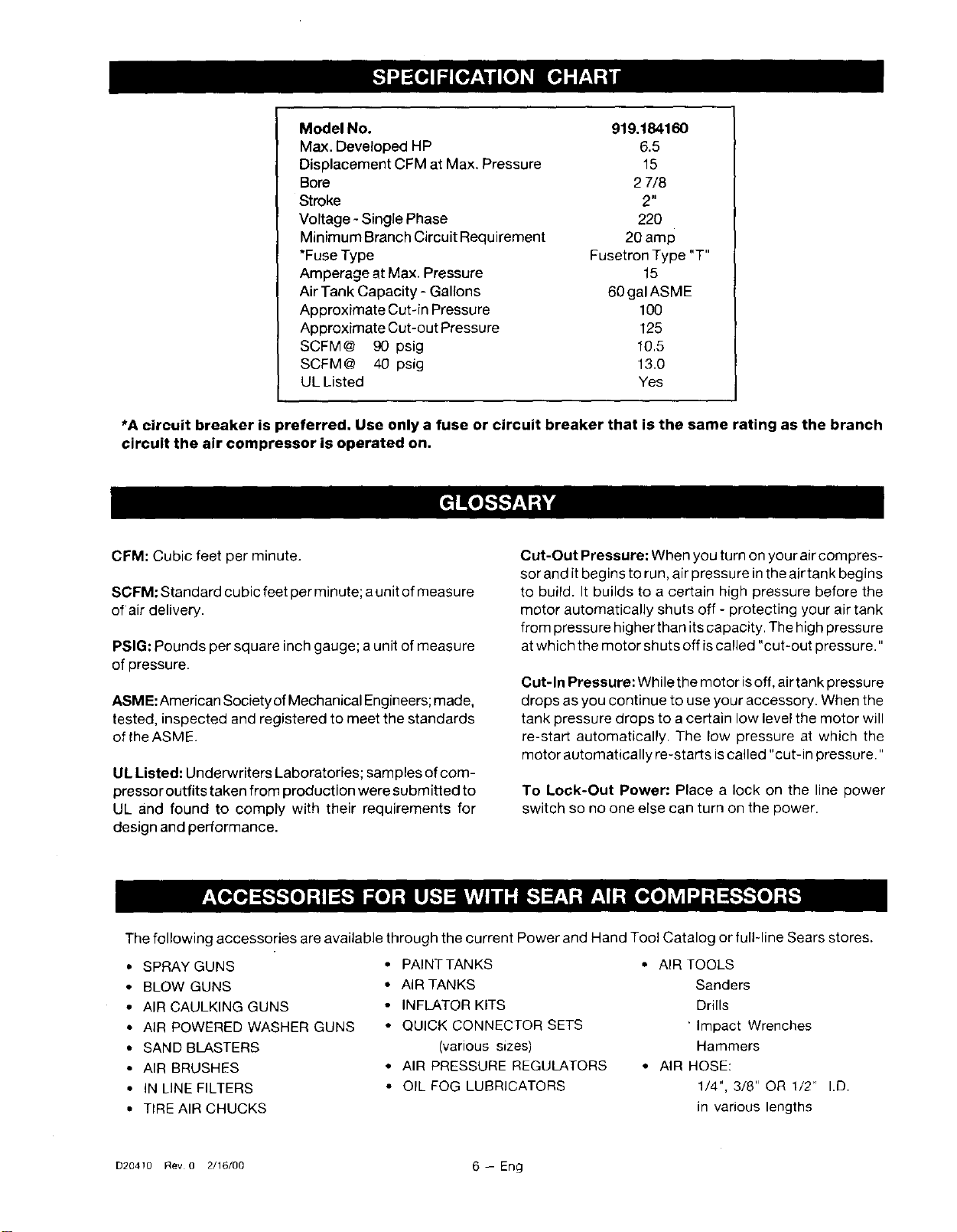
Model No. 919.184160
Max. Developed HP 6.5
Displacement CFM at Max. Pressure 15
Bore 2 7/8
Stroke 2"
Vortage - Single Phase 220
Minimum Branch Circuit Requirement 20 amp
*Fuse Type Fusetron Type "T"
Amperage at Max. Pressure 15
Air Tank Capacity - Gallons 60 gal ASME
Approximate Cut-in Pressure 100
Approximate Cut-out Pressure 125
SCFM@ 90 psig 10.5
SCFM@ 40 psig 13.0
UL Listed Yes
*A circuit breaker is preferred. Use only a fuse or circuit breaker that is the same rating as the branch
circuit the air compressor is operated on.
CFM: Cubic feet per minute.
SCFM: Standard cubic feet per minute; aunit of measu re
of air delivery.
PSIG: Pounds per square inch gauge; a unit of measure
of pressure.
ASME: American Society of Mechanical Engineers; made,
tested, inspected and registered to meet the standards
of the ASME.
UL Listed: Underwriters Laboratories;samples of com-
pressor outfits taken from production were submitted to
UL and found to comply with their requirements for
design and performance.
Cut-Out Pressure: When you turn on your aircompres-
sor and it begins to run, air pressure inthe air tank begins
to build. It builds to a certain high pressure before the
motor automatically shuts off - protecting your air tank
from pressure higher than its capacity. The high pressure
at which the motor shuts off is called "cut-out pressure."
Cut-In Pressure: While the motor isoff, airtank pressure
drops as you continue to use your accessory. When the
tank pressure drops to acertain low level the motor will
re-start automatically. The low pressure at which the
motor automatically re-starts iscalled "cut-in pressure."
To Lock-Out Power: Place a lock on the line power
switch so no one else can turn on the power.
The following accessories are available through the current Power and Hand Tool Catalog or fuIFline Sears stores.
• SPRAY GUNS
• BLOW GUNS
• AIR CAULKING GUNS
• AIR POWERED WASHER GUNS
• SAND BLASTERS
• AIR BRUSHES
• IN LINE FILTERS
• TIRE AIR CHUCKS
• PAINT TANKS
• AIR TANKS
• INFLATOR KITS
• QUICK CONNECTOR SETS
(various sizes)
• AIR PRESSURE REGULATORS
• OIL FOG LUBRICATORS
• AIR TOOLS
Sanders
Drills
"Impact Wrenches
Hammers
• AIR HOSE:
1/4", 3/8" OR 1/2" I.D.
in various lengths
D204!0 Rev 0 2/16/00 6 -- Eng
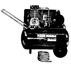
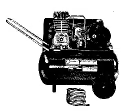
You have purchased an aircompressor unit consisting of
a two cylinder, single stage air compressor pump, an
ASM Eair tank, associated controls and instruments. This
air compressor must be permanently mounted in place.
Your air compressor can be used for operating paint
spray guns, air tools, caulking guns, grease guns, air
brushes, sandblasters, inflating tires and plastic toys,
spraying weed killers, insecticides, etc. An air pressure
regulator is usually necessary for most of these applica-
tions. Regulators can be purchased from most Sears
stores or through the current Sears Power and Hand Tool
Catalog.
Separate airtransformers which combine thefunctions of
air regulation and/or moisture and dirt removal should be
used where applicable.
Some form of piping or shut-off valve must be installed
before operating the aircompressor. A 1/2" NPTshut-off
globe valve should be installed at the air compressor
tank. Do not use a ball valve.
Air Compressor Pump: To compress air, the pistons
move up and down in the cylinders. On the downstroke,
air isdrawn inthrough the air intake filter and then through
the air intake valves. The exhaust valve remains closed.
On the upstroke of the piston, air is compressed. The
intake valves close and compressed air is forced out
through the exhaust valves, through the outlet tube,
through the check valve and into the airtank. Working air
is not available until the compressor has raised air tank
pressure above that required at the air outlet.
Check Valve: When the air compressor isoperating, the
check valve is "open," allowing compressed airto enter
the air tank. When the air compressor reaches "cut-out"
pressure, the check valve "closes," allowing air pressure
to remain inside the air tan k. If the air isnot unloaded, the
motor will try to start, but will be unable to. The check
valve allows the motor to re-start freely.
Pressure Switch: The pressure switch automatically
starts
the motor when the air tank pressure drops below the
factory set "cut-in" pressure, it stops the motor when the
air tank pressure reaches the factory set "cut-out"
pressure.
Pressure Release Valve: The pressure release valveis
designed to automatically release compressed airfrom
the compressor head and the outlet tube when the air
compressor reaches "cut-out" pressure or isshut off. If
the air is not released, the motor willtry to start but will
be unable to. The pressure release valve allows the
motor to restartfreely.Whenthemotor stops running,air
willbe heard escaping for a few seconds. No airshould
be heard leaking when the motor isrunning.
SafetyValve: ifthe pressure switch does not shut off the
air compressor at or near its cut-out pressu resetting, the
safety valve will protect against high pressure by "pop-
ping out" at its factory set pressure (slightly higher than
the pressure switch cut-out setting).
Location of the Air Compressor
Operate the air compressor in a clean, dry and well
ventilated area. The airintake filter must be kept clear of
obstructions which could reduce air delivery of the air
compressor. The air compressor should be located at
least12"away from walls orotherobstructionsthatcould
interfere with the flow of air through the fan bladed
flywheel. The air compressor crankcase and head are
designed with fins to provide proper cooling. If the
humidity is high, a Sears air filter can be installed to
remove excessive moisture.
The air compressor should be as near to air outlets as
possible inorder to avoid long pipe lines.Do not placethe
air compressor where heat is excessive.
7 -- Eng 020410 Rev 0 2/16/00
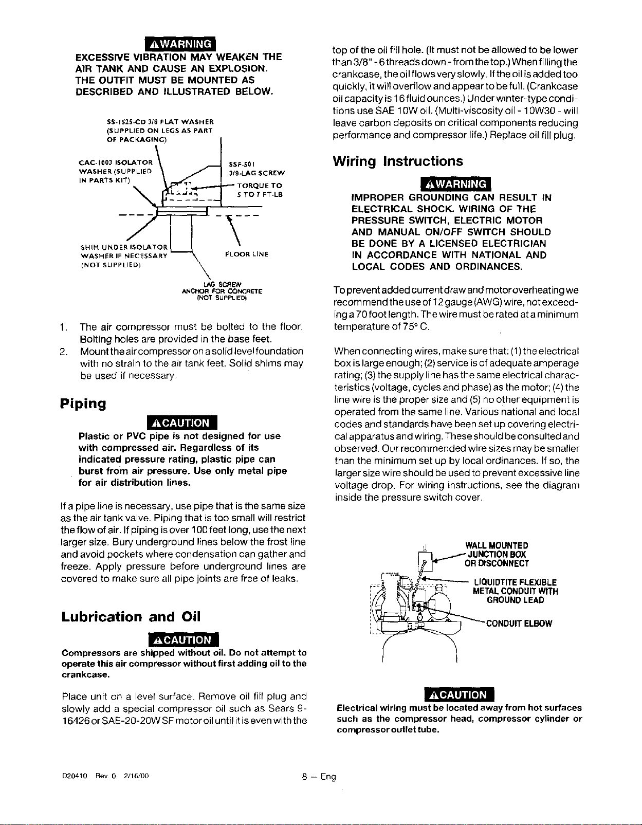
EXCESSIVE VIBRATION MAY WEAKEN THE
AIR TANK AND CAUSE AN EXPLOSION.
THE OUTFIT MUST BE MOUNTED AS
DESCRIBED AND ILLUSTRATED BELOW.
SS-IE2E-CD 3t8 FLAT WASHER
(SUPPUED ON LEGS AS PART
OF PACKAG4NG) I
WASHER IF NECESSARY "_ FLOOR LINE
(NOT SUPPLIED) X
SCREW
ANCHOR FOR CONC_I_TE
{NO'_ SUPPLIED_
1. The air compressor must be bolted to the floor.
Bolting holes are provided in the base feet.
2. Mount the air compressor on a sorid levelfoundation
with no strain to the air tank feet. Solid shims may
be used if necessary.
Piping
_l[o]_l
Plastic or PVC pipe is not designed for use
with compressed air. Regardless of its
indicated pressure rating, plastic pipe can
burst from air pressure. Use only metal pipe
for air distribution lines.
ffa pipe line is necessary, use pipe that isthe same size
as the air tank valve. Piping that is too small will restrict
the flow of air. Ifpiping isover 100 feet long, use the next
larger size. Bury underground lines below the frost line
and avoid pockets where condensation can gather and
freeze. Apply pressure before underground lines are
covered to make sure all pipe joints are free of leaks.
Lubrication and Oil
_tT@_nji[o] _I
Compressors are shipped without oil. Do not attempt to
operate this air compressor without first adding oil to the
crankcase.
Place unit on a level surface. Remove oil fill plug and
slowly add a special compressor oil such as Sears 9-
16426 or SAE-20-20W SF motor oil until it is even with the
top of the oil fillhole. (It must not be allowed to be lower
than 3/8" - 6threads down - from the top.) When filling the
crankcase, the oilflows very slowly. Ifthe oil isadded too
quickly, it willoverflow and appear to befull. (Crankcase
oil capacity is 16 fluid ounces.) Under winter-type condi-
tions use SAE 10W oil. (Multi-viscosity oil - 10W30 - will
leave carbon deposits on critical components reducing
performance and compressor life.) Replace oil fill plug.
Wiring Instructions
IMPROPER GROUNDING CAN RESULT IN
ELECTRICAL SHOCK. WIRING OF THE
PRESSURE SWITCH, ELECTRIC MOTOR
AND MANUAL ON/OFF SWITCH SHOULD
BE DONE BY A LICENSED ELECTRICIAN
IN ACCORDANCE WITH NATIONAL AND
LOCAL CODES AND ORDINANCES.
To prevent added current draw andmotoroverheating we
recommend the use of 12 gauge (AWG)wire, not exceed-
ing a 70 foot length. The wire must berated at aminimum
temperature of 75°C.
When connecting wires, make sure that: (1)the electrical
box is large enough; (2)service isof adequate amperage
rating; (3)the supply line has the same electrical charac-
teristics (voltage, cycles and phase) as the motor; (4)the
line wire is the proper size and (5) no other equipment is
operated from the same line. Various national and local
codes and standards have been set up covering electri-
cal apparatus and wiring. These should be consulted and
observed. Our recommended wire sizes may be smaller
than the minimum set up by local ordinances. If so, the
larger size wire should be used to prevent excessive line
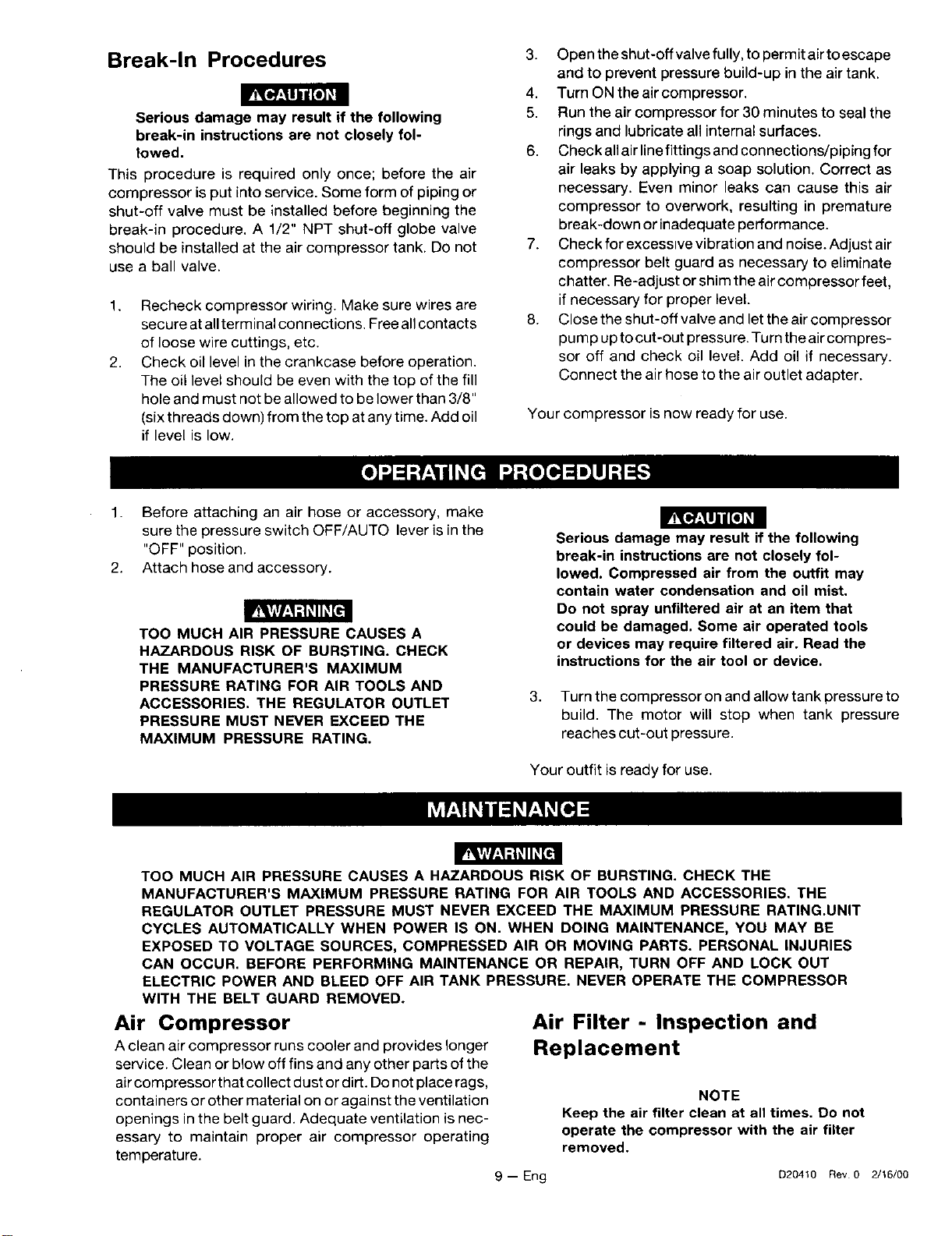
voltage drop. For wiring instructions, see the diagram
inside the pressure switch cover.
r,==tu._
t
r
WALLMOUNTED
._oJU NCTIONBOX
RDISCONNECT
LIQUIDTITEFLEXIBLE
METALCONDUITWITH
, GROUNDLEAD
_ _ CONDUITELBOW
Electrical wiring must be located away from hot surfaces
such as the compressor head, compressor cylinder or
compressor outlet tube.
D20410 Rev 0 2/16/00 8 -- Eng
Break-In Procedures
i rR[_'_klJid[o]_I
Serious damage may result if the following
break-in instructions are not closely fol-
lowed,
This procedure is required only once; before the air
compressor is put into service. Some form of piping or
shut-off valve must be installed before beginning the
break-in procedure. A 1/2" NPT shut-off globe valve
should be installed at the air compressor tank. Do not
use a ball valve,
1,
2.
Recheck compressor wiring. Make sure wires are
secure at allterminal connections. Free all contacts
of loose wire cuttings, etc.
Check oil level in the crankcase before operation.
The oil level should be even with the top of the fill
hole and must not be allowed to be lower than 3/8"
(six threads down) from the top at any time. Add oil
if level is low.
3. Open the shut-off valve fully, to permit airto escape
and to prevent pressure build-up in the air tank.
4. Turn ONtheaircompressor.
5. Run the air compressor for 30 minutes to seal the
rings and lubricate all internal surfaces.
6. Check all air line fittings and connections/piping for
air leaks by applying a soap solution. Correct as
necessary. Even minor leaks can cause this air
compressor to overwork, resulting in premature
break-down or inadequate performance.
7. Check for excessive vibration and noise. Adjust air
compressor belt guard as necessary to eliminate
chatter. Re-adjust or shim the aircompressor feet,
if necessary for proper level.
8. Close the shut-off valve and let the air compressor
pump up to cut-out pressure. Turn the air compres-
sor off and check oil level. Add oil if necessary.
Connect the air hose to the air outlet adapter.
Your compressor is now ready for use.
1. Before attaching an air hose or accessory, make
sure the pressure switch OFF/AUTO lever is in the
"OFF" position.
2. Attach hose and accessory.
IVt_[o,7_a]id[o]_1
TOO MUCH AIR PRESSURE CAUSES A
HAZARDOUS RISK OF BURSTING. CHECK
THE MANUFACTURER'S MAXIMUM
PRESSURE RATING FOR AIR TOOLS AND
ACCESSORIES. THE REGULATOR OUTLET
PRESSURE MUST NEVER EXCEED THE
MAXIMUM PRESSURE RATING.
Serious damage may result if the following
break-in instructions are not closely fol-
lowed. Compressed air from the outfit may
contain water condensation and oil mist.
Do not spray unfiltered air at an item that
could be damaged. Some air operated tools
or devices may require filtered air. Read the
instructions for the air tool or device.
3. Turn the compressor on and allow tank pressure to
build. The motor will stop when tank pressure
reaches cut-out pressure.
Your outfit is ready for use.
TOO MUCH AIR PRESSURE CAUSES A HAZARDOUS RISK OF BURSTING. CHECK THE
MANUFACTURER'S MAXIMUM PRESSURE RATING FOR AIR TOOLS AND ACCESSORIES. THE
REGULATOR OUTLET PRESSURE MUST NEVER EXCEED THE MAXIMUM PRESSURE RATING.UNIT
CYCLES AUTOMATICALLY WHEN POWER IS ON. WHEN DOING MAINTENANCE, YOU MAY BE
EXPOSED TO VOLTAGE SOURCES, COMPRESSED AIR OR MOVING PARTS. PERSONAL INJURIES
CAN OCCUR. BEFORE PERFORMING MAINTENANCE OR REPAIR, TURN OFF AND LOCK OUT
ELECTRIC POWER AND BLEED OFF AIR TANK PRESSURE. NEVER OPERATE THE COMPRESSOR
WITH THE BELT GUARD REMOVED.
Air Compressor
A clean air compressor runs cooler and provides longer
service. Clean or blow off fins and any other parts of the
air compressor that collect dust or dirt. Do not place rags,
containers or other material on or agai net the ventilation
openings in the belt guard. Adequate ventilation is nec-
essary to maintain proper air compressor operating
temperature.
Air Filter - Inspection and
Replacement
9 -- Eng
NOTE
Keep the air filter clean at all times. Do not
operate the compressor with the air filter
removed.
e20410 Rev 0 2/16/00
A dirty air filter will not allow the compressor to operate
at full capacity. Before you use the comoressor, check
the air filter to be sure it is clean.
If it isdirty, remove the screws and filter retainer. Pullout
the filter, replace with new.
Oil - Checking and Changing
5. Apply sealant to the check valve threads.Reinstall
the check valve (turn clockwise). The valve stem
should still move freely do not over tighten.
6. Replace the outlet tube and tighten top and bottom
nuts.
Safety Valve - Inspection
Overfilling with oil will cause premature
compressor failure. Do not overfill.
Check oil level inthe crankcase daily. The oil level should
be even with the top of the fill hole and must not be
allowed to be lower than 3/8" from the top (6threads) at
anytime. Itisrecommended that the oil be changed after
every 100 hours of operation. To drain the oil, remove the
oil drain plug and collect the oil in asuitable container. Be
sure to replace the plug securely before adding new oil.
Use a special compressor oil such as Sears 9-16426 or
SAE-20-20W SF motor oil. (Crankcase oil capacity is 16
fluid ounces.) Under extreme winter conditions use 10
weight oil.
Air Tank - Draining Water
WATER WILL CONDENSE IN THE AIR
TANK. IF NOT DRAINED, THE WATER WILL
CORRODE AND WEAKEN THE AIR TANK
CAUSING A RISK OF AIR TANK RUPTURE.
Water should be drained from the air tank after each use.
Operate the unit to apply 15-20 PSIG and open the drain
cock. Continue operating unit untir all moisture is re-
moved from the air tank. Close the drain cock tightly.
NOTE
If drain cock valve is clogged, release sir
pressure in air tank. The drain cock valve
can then be removed, cleaned and rein-
stalled.
Check Valve - Inspection and
Replacement
Remove the check valve for inspection or replacement if
air tank pressure will not build up. Use the following
procedure to inspect, clean or replace the check valve.
1. Release air pressure from the air tank.
2. Loosen the top and bottom nuts and remove the
outlet tube.
3. Unscrew the check valve (turn counterclockwise)
using a 7/8" diameter 1/2" socket wrench.
4. Check that the valve disc moves freely inside the
check valve and that the spring holds the disc in the
upper, closed position. The check valve may be
cleaned with a solvent.
IF THE SAFETY VALVE DOES NOT WORK
PROPERLY OVER-PRESSURIZATION MAY
OCCUR, CAUSING AIR TANK RUPTURE
OR EXPLOSION. OCCASIONALLY PULL
THE RING ON THE SAFETY VALVE TO
MAKE SURE THAT THE SAFETY VALVE
OPERATES FREELY, IF THE VALVE IS
STUCK OR DOES NOT OPERATE
SMOOTHLY, IT MUST BE REPLACED WITH
THE SAME TYPE OF VALVE.
Motor
The motor has athermal overload protector. If the motor
overheats for any reason, the overload protector will shut
off the motor. The motor must be allowed to cool down
before restarting. De-energize power supply. To restart,
depress the reset button located on the end ofthe motor
and energize the power supply.
NOTE
If the overload protector shuts the motor
off frequently, check for a possible voltage
problem. Low voltage can also be sus-
pected when:
1. the motor does not get up to full power
or speed;
2. fuses blow out when the motor is
started;
3. lights dim when motor is started and
remain dim while it is running.
Belt - Replacement
SERIOUS INJURY OR DAMAGE MAY OCCUR IF PARTS OF
THE BODY OR LOOSE ITEMS GET CAUGHT IN MOVING
PARTS, NEVER OPERATE THE COMPRESSOR WITH THE
BELT GUARD REMOVED. THE BELT GUARD SHOULD BE
REMOVED ONLY WHEN THE POWER TO THE COMPRES-
SOR IS DISCONNECTED.
The motor is mounted on an adjustable motor base.
To replace belt:
1. Turn off and lock out power source.
2. Remove screws from the back of the belt guard.
3. Loosen the four motor mounting screws.
4. Slide the motor toward the compressor pump.
5. Remove belt and replace.
D20410 Rev 0 2/16/00 10 -- Eng
NOTE
The belt should be centered over the
grooves on the flywheel and motor pulley.
6. Pushthe motor back into regular position and tighten
bolts securely. Proper tension isapproximately 1/4"
belt deflection measured midway between the pul-
ley and flywheel when a 3 pound weight or equiva-
lent finger pressure is applied at this point. A loose
belt will squeal at compressor start-up.
7. Replace beltguard and screws.
Pulley and Flywheel - Alignment
The compressor flywheel and motor pulley must be inline
(in the same plane) within 1/16" to assure belt retention
within sheave grooves. The motor mounting holes on the
saddle are skewed to square the motor with the com-
pressor mounting hole as the belt is tensioned. To check
alignment, disconnect electrical power and remove the
belt guard. Place a straightedge against the outside of the
flywheel and measure the distance from it to the nearest
groove. Alignment is achieved when the other end of the
straightedge is within 1/16" of the measured dimension
at the pulley grooves. Squareness is achieved when the
pulley grooves are an equal distance from the straight-
edge on both sides of the motor shaft.
UNIT CYCLES AUTOMATICALLY WHEN POWER IS ON. WHEN DOING MAINTENANCE, YOU MAY BE
EXPOSED TO VOLTAGE SOURCES, COMPRESSED AIR OR MOVING PARTS. PERSONAL INJURIES
CAN OCCUR. BEFORE PERFORMING MAINTENANCE OR REPAIR, TURN OFF AND LOCK OUT
ELECTRIC POWER AND BLEED OFF AIR TANK PRESSURE. NEVER OPERATE THE COMPRESSOR
WITH THE BELT GUARD REMOVED.
PROBLEM
Excessive tank pressure- safety
valve pops off.
CAUSE CORRECTION
Pressure switch must be replaced.Pressure sw!tch does not shut off motor
when compressor reaches "cut-out" pres-
sure.
Air leaks at fittings or hose. Tube or hose fittings are not tight enough. Tighten fittings where air can be heard escaping,
Check fittings under soapy water solution. DO NOT
OVER-TIGHTEN.
Air leaks at check valve. Defective or dirty check valve. Remove and clean or replace check valve. DO NOT
OVER-TIGHTEN.
Air leaks st pressure switch re- Dsfectivepressureswitch releasevalve. Removeand replaoetherelsasevalve.
lease valve.
Air leaks at air tank welds. Defective air tank. Air tank must be replaced.
iP'_W_d_] _1_
Air leak from safety valve.
Possible defect in safety valve.
Restricted checkvalve.
Loose pulley.
Low oil level.
Loose flywheel.
Loose compressor bolts.
Loose belt.
Carbon build-up.
DO NOT DRILL INTO, WELD OR
OTHERWISE MODIFY AIR TANK. IT
WILL BE WEAKENED.
Operate safety valve manually be pulling on ring. If
valve still leaks, it should be replaced.
Remove and clean or replace.
Tighten pulley set screw.
Maintain prescribed oil level.
Tighten screw.
Check bolts. Tighten as required.
Tighten belt as per instructions under Belt Replace-
ment above.
Remove the head and valve plate. Clean the valve
_lateand the top of the piston. (Be sure carbon does
not fall into t hecylinder.) Reassemble to 25-30 ft.lbs.
using new gasket and torque screws.
11 -- Eng D20410 Rev 0 2116/00
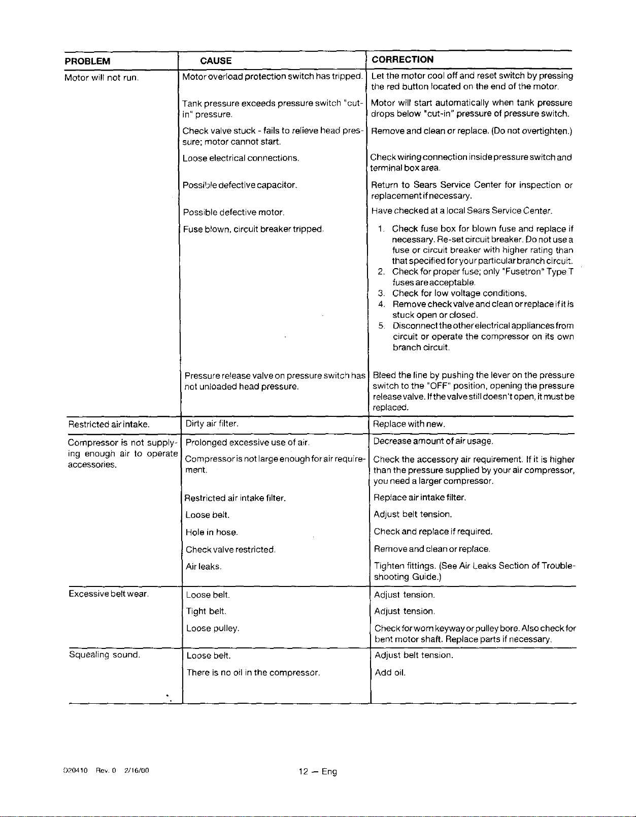
PROBLEM
Motor will not run.
Restricted air intake.
Compressor is not supply-
ing enough air to operate
accessories.
Excessive belt wear.
Squealing sound.
CAUSE
Motor overload protection switch has tripped.
Tank pressure exceeds pressure switch "cut-
in" pressure.
Check valve stuck - fails to relieve head pres-
sure; motor cannot start.
Loose electrical connections.
Possibte defective capacitor.
Possible defective motor.
Fuse blown, circuit breaker tripped.
Pressure release valve on pressure switch has
not un}oaded head pressure.
Dirty air filter.
Prolonged excessive use of air.
Compressor is not large enough for air require-
ment.
Restricted air intake filter.
Loose belt.
Hole in hose.
Check valve restricted,
Air leaks.
Loose belt.
Tight belt.
Loose pulley.
Loose be_t.
There is no oil in the compressor.
CORRECTION
Let the motor cool off and reset switch by pressing
the red button located on the end of the motor.
Motor wilt start automatically when tank pressure
drops below "cut-in" pressure of pressure switch.
Remove and clean or replace. (Do not overtighten.)
Check wiring connection inside pressure switch and
terminal box area.
Return to Sears Service Center for inspection or
replacement if necessary.
Have checked at alocal Sears Service Center.
1. Check fuse box for blown fuse and replace if
necessary. Re-set circuit breaker. Do not use a
fuse or circuit breaker with higher rating than
that specified for your particular branch circuit.
2. Check for proper fuse; only "Fusetron" Type T
fuses are acceptable.
3. Check for low voltage conditions.
4. Removecheckvalveandcleanorreplaceifitis
stuck open or closed.
5. Disconnect the other electrical appliances from
circuit or operate the compressor on its own
branch circuit.
I Bleed the line by pushing the lever on the pressure
switch to the "OFF" position, opening the pressure
release valve. Ifthe valve still doesn't open, it must be
replaced.
Replace with new.
Decrease amount of air usage.
Check the accessory air requirement. If it is higher
than the pressure supplied by your air compressor,
you need a larger compressor.
Replace air intake filter.
Adjust belt tension.
Check and replace if required.
Remove and clean or replace,
Tighten fittings. (See Air Leaks Section of Trouble-
shooting Guide.)
Adjust tension.
Adjust tension.
Check for worn keyway or pulley bore. Also check for
bent motor shaft. Replace parts if necessary.
Adjust belt tension.
Add oil.
D20410 Rev 0 2/16/00 12 -- Eng
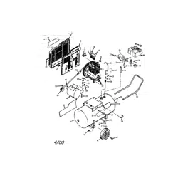
13 -- Eng D20410 Rev 0 2/16/00
11 12
10 _ 13
15
42
36 _14
22
) 21
23
35
\\
\\\\\
\
\\
\
31
27
D20410 Rev. 0 2/16/00 14 -- Eng
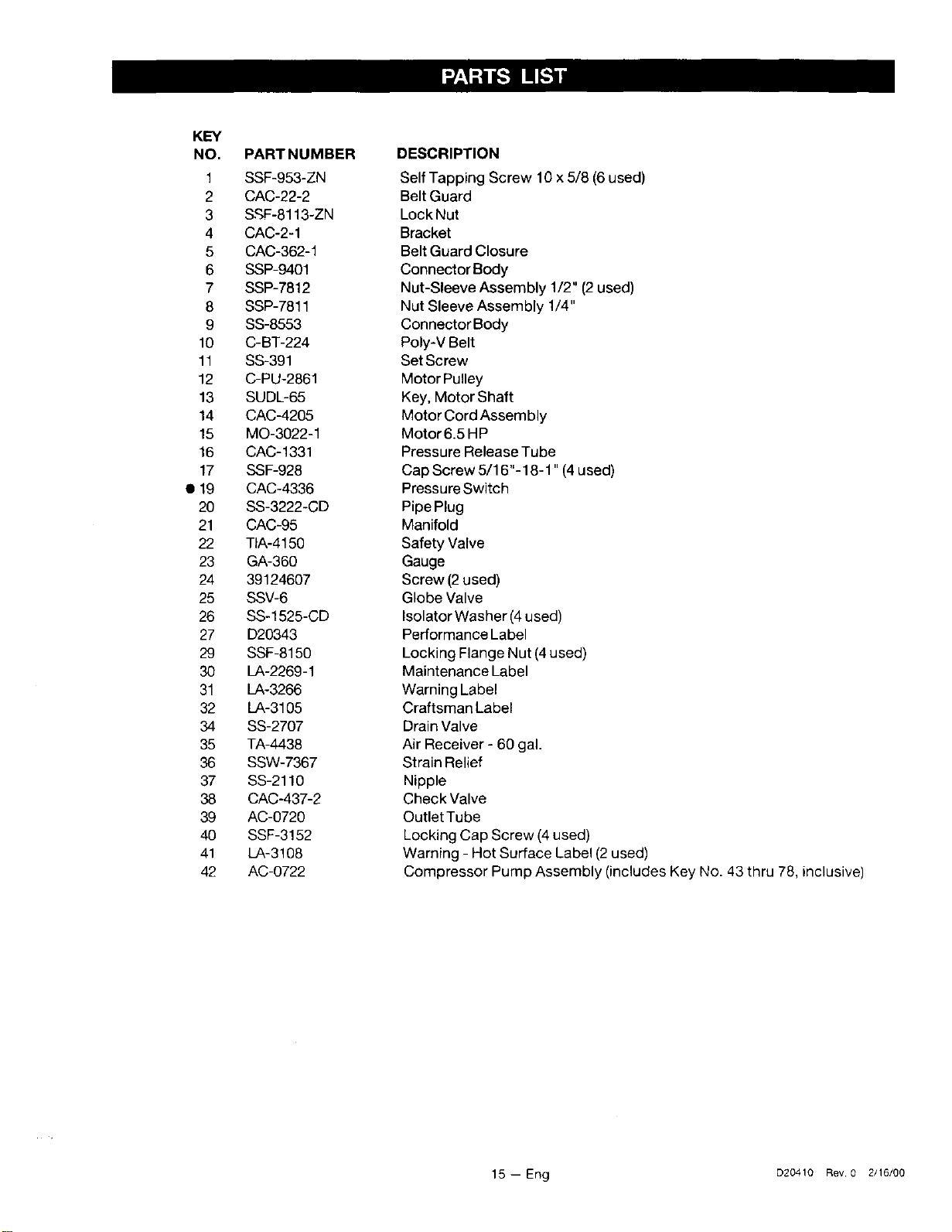
KEY
NO. PART NUMBER
1 SSF-953-ZN
2 CAC-22-2
3 &£F-8113-ZN
4 CAC-2-1
5 CAC-362-1
6 SSP-9401
7 SSP-7812
8 SSP-7811
9 SS-8553
10 C-BT-224
11 SS-391
12 C-PU-2861
13 SUDL-65
14 CAC-4205
15 MO-3022-1
16 CAC-1331
17 SSF-928
• 19 CAC-4336
20 SS-3222-CD
21 CAC-95
22 TIA-4150
23 GA-360
24 39124607
25 SSV-6
26 SS-1525-CD
27 D20343
29 SSF-8150
30 LA-2269-1
31 LA-3266
32 LA-3105
34 SS-2707
35 TA-4438
36 SSW-7367
37 SS-2110
38 CAC-437-2
39 AC-0720
40 SSF-3152
41 LA-3108
42 AC-0722
DESCRIPTION
Self Tapping Screw 16 x 5/8 (6 used)
Belt Guard
LockNut
Bracket
Belt Guard Closure
Connector Body
Nut-Sleeve Assembly 1/2" (2 used)
Nut Sleeve Assembly 1/4"
Connector Body
Poly-V Belt
SetScrew
Motor Pulley
Key, Motor Shaft
Motor Cord Assembly
Motor6.5 HP
Pressure Release Tube
Cap Screw 5/16"-18-1" (4 used)
Pressure Switch
Pipe Plug
Manifold
Safety Valve
Gauge
Screw (2 used)
Globe Valve
Isolator Washer (4used)
Performance Label
Locking Flange Nut (4 used)
Maintenance Label
Warning Label
Craftsman Label
Drain Valve
Air Receiver - 60 gal.
Strain Relief
Nipple
Check Valve
OutletTube
Locking Cap Screw (4used)
Warning - Hot Surface Label (2 used)
Compressor Pump Assembly (includes Key No. 43 thru 78, inclusive)
15 -- Eng D20410 Rev 0 2/16/00
76
74
65
/
72
4 45
53_ *;'-_,.--52
70
66 (oil drain plug)
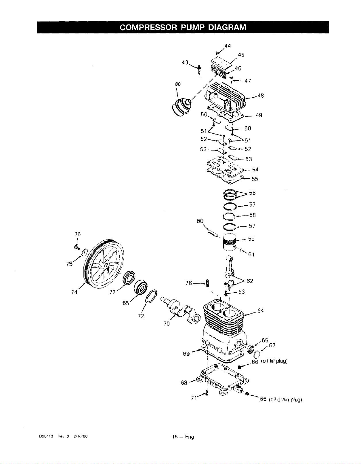
D20410 Rev 0 2/16/00 16 -- Eng
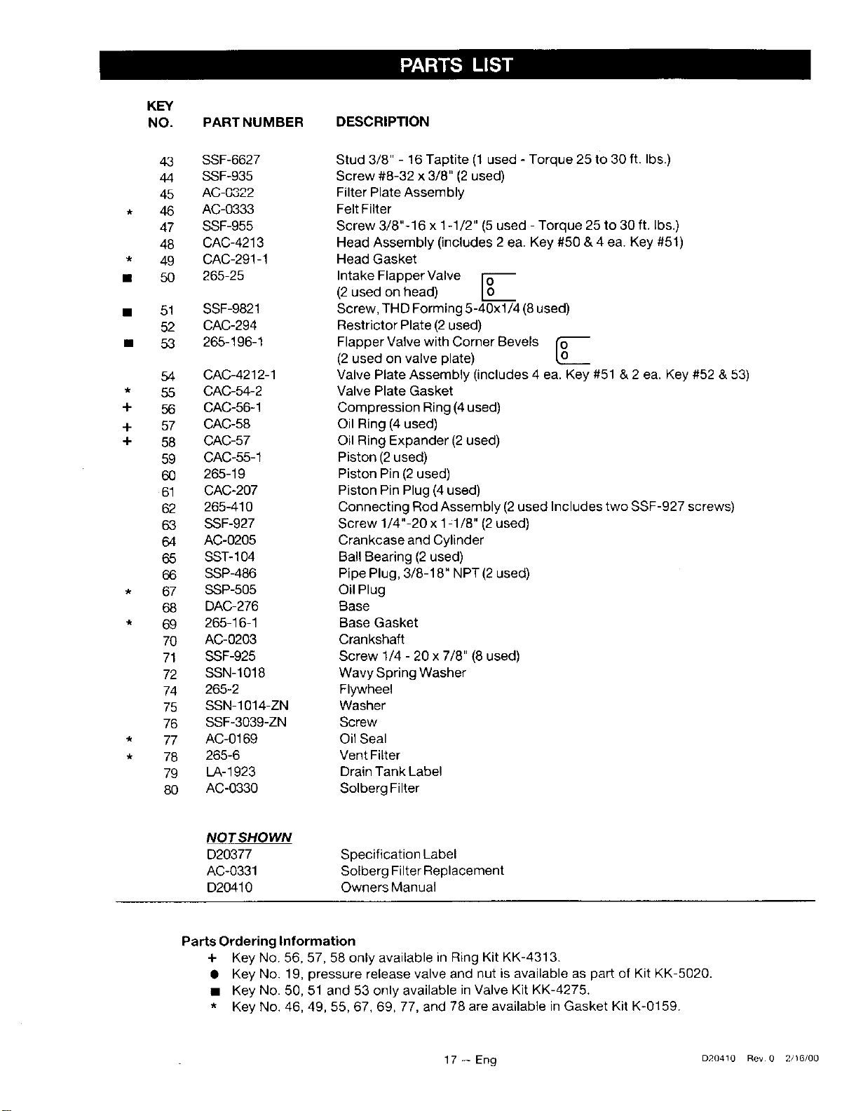
K_
NO. PARTNUMBER DESCRIPTION
43 SSF-6627
44 SSF-935
45 AC-0322
* 46 AC-0333
47 SSF-955
48 CAC-4213
* 49 CAC-291-1
• 50 265-25
• 51 SSF-9821
52 CAC-294
• 53 265-196-1
54 CAC-4212-1
* 55 CAC-54-2
+ 56 CAC-56-1
4- 57 CAC-58
4- 58 CAC-57
59 CAC-55-1
60 265-19
61 CAC-2O7
62 265-410
63 SSF-927
64 AC-0205
65 SST-104
66 SSP-486
* 67 SSP-505
68 DAC-276
* 69 265-16-1
70 AC-0203
71 SSF-925
72 SSN-1018
74 265-2
75 SSN-1014-ZN
76 SSF-3039-ZN
* 77 AC-0169
* 78 265-6
79 LA-1923
80 AC-0330
Stud 3/8" - 16 Taptite (1 used - Torque 25 to 30 ft. Ibs.)
Screw #8-32 x 3/8" (2used)
Filter Plate Assembly
Felt Filter
Screw 3/8"-16 x 1-1/2" (5 used - Torque 25 to 30 ft. Ibs.)
Head Assembly (includes 2 ea. Key #50 & 4 ea. Key #51)
Head Gasket
Intake Flapper Valve [n
(2 used on head)
Screw, THD Forming 5-40xl/4 (8 used)
Restrictor Plate (2 used)
FlapperValve with Corner Bevels I_"
(2 used on valve plate)
OL0___
Valve Plate Assembly (includes 4 ea. Key #51 & 2 ea. Key #52 & 53)
Valve Plate Gasket
Compression Ring (4 used)
Oil Ring (4 used)
Oil Ring Expander (2 used)
Piston (2used)
Piston Pin (2 used)
Piston Pin Plug (4 used)
Connecting Rod Assembly (2 used Includes two SSF-927 screws)
Screw 1/4"-20 x 1:1/8" (2 used)
Crankcase and Cylinder
Ball Bearing (2 used)
Pipe Plug, 3/8-18" NPT (2used)
Oil Plug
Base
Base Gasket
Crankshaft
Screw 1/4 - 20 x 7/8" (8 used)
Wavy Spring Washer
Flywheel
Washer
Screw
Oil Seal
Vent Filter
Drain Tank Label
Solberg Filter
NOT SHOWN
D20377
AC-0331
D20410
Specification Label
Solberg Filter Replacement
Owners Manual
Parts Ordering Information
+ Key No. 56, 57, 58 only available in Ring Kit KK-4313.
• Key No. 19, pressure release valve and nut isavailable as part of Kit KK-5020.
• Key No. 50, 51 and 53 only available in Valve Kit KK-4275.
* Key No. 46, 49, 55, 67, 69, 77, and 78 are available in Gasket Kit K-0159.
17 -- Eng D20410 Rev 0 2/16/00
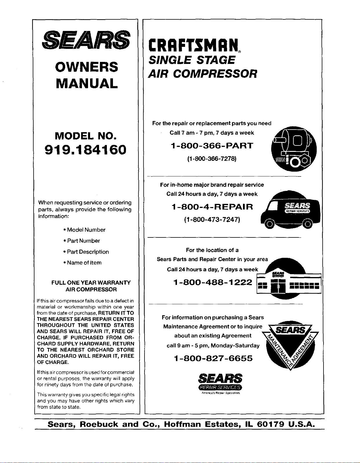
SEARS
OWNERS
MANUAL
MODEL NO.
919.184160
When requesting service or ordering
parts, always provide the following
information:
• Model Number
• Part Number
• Part Description
• Name of Item
FULL ONE YEAR WARRANTY
AIR COMPRESSOR
Ifthis air compressor fails due to a defect in
material or workmanship within one year
from the date of purchase, RETURN IT TO
THE NEAREST SEARS REPAIR CENTER
THROUGHOUT THE UNITED STATES
AND SEARS WILL REPAIR IT, FREE OF
CHARGE. IF PURCHASED FROM OR-
CHARD SUPPLY HARDWARE, RETURN
TO THE NEAREST ORCHARD STORE
AND ORCHARD WILL REPAIR IT, FREE
OF CHARGE.
Ifthis air compressor is used for commercial
or rental purposes, the warranty will apply
for ninety days from the date of purchase.
t'=1€p._J/_r.,,pJ_ll[ef iJ
This warranty gives you specific legal rights
and you may have other rights which vary
from state to state.
I:RRFI"$MRNo
SINGLE STAGE
AIR COMPRESSOR
For the repair or replacement parts you need
Call 7 am - 7 pm, 7 days a week
1-800-366-PART
(1-800-366-7278)
For in-home major brand repair service
Call 24 hours a day, 7 days a week
1 -800-4-REPAIR
(1-800-473-7247)
For the location of a
SearPasanReparCenernyour rea--
Call 24 hours a day, 7 days a wee
1-800-488-1222
For information on purchasing a Sears
Maintenance Agreement or to inquir, _i_j_7
about an existing Agreement
call 9 am - 5 pro, Monday-Saturday
,
SEARS
America's Repair _F:_ah_
Sears, Roebuck and Co., Hoffman Estates, IL 60179 U.S.A.