
perator's
I:RnFrSMRN°
LAWN TRACTOR
20 Horsepower
Hydrostatic Transmission
42" Deck
Mode[ No. 247.28905
• Espanol, P. 59
This product has a low emission engine which operates differently
from previously built engines. Before you start the engine, read and
understand this Operator's Manual.
Before using this equipment,
read this manual and follow
all safety rules and operating
instructions.
For answers to your questions about
this product, Call:
1-800=659=5917
Craftsman Tractor Help Line
7 am = 7 pm CT, Mort. =Sun.
Sears Brands Management Corporation, Hoffman Estates, IL 60179 U.S.A.
Visit our website: www.craftsman.com
FormN0,769-05573B
(March30,2010)
Off-Season Storage ........................................................ 27
Trou bleshooting .............................................................. 28
Labels ............................................................................. 29
Parts List ......................................................................... 30
Espafiol ............................................................................ 59
Service Numbers ............................................. Back Cover
CRAFTSMAN FULL WARRANTY
Whenoperatedand maintainedaccordingto allsuppliedinstructions,ifany non-expendablepartof thisridingequipmentfails dueto a defectin
materialor workmanshipwithintwo yearsfrom thedate orpurchase,call 1-800-659-5917to arrangefor free in-homerepair.
Theframeandfrontaxle will be repairedfreeof chargefor five yearsfromthe dateof purchaseif defectiveinmaterialor workmanship.
Allof the abovewarrantycoverageappliesfor only90 daysfromthe dateof purchaseifthis ridingequipmentiseverusedfor commercialor
rentalpurposes.
In all cases,if repairprovesimpossible,the ridingequipmentwill be replacedfree of chargewiththe sameoran equivalentmodel.
The batterywill be replacedfree of chargefor 90 daysfromthe dateof purchaseifdefectiveinmaterialorworkmanship(ourtestingprovesthat it
will nothold a charge).
Thiswarranty coversONLYdefects in material and workmanship. Sears will NOTpayfor:
o
o
o
o
Expendableitemsthatbecomewornduringnormaluse,includingbutnot limitedto blades,spark plugs,aircleaners,belts,
andoil filters.
Standardmaintenanceservicing,oilchanges,or tune-ups.
Tire replacementor repaircausedby puncturesfromoutsideobjects,suchas nails,thorns,stumps,or glass.
Tireor wheelreplacementor repairresultingfromnormalwear,accident,orimproperoperationor maintenance.
Repairsnecessarybecauseof operatorabuse,includingbutnot limitedto damagecausedby towingobjectsbeyondthe
capabilityof the ridingequipment,impactingobjectsthat bendtheframeor crankshaft,or over-speedingthe engine.
Repairsnecessarybecauseof operatornegligence,includingbut not limitedto, electricaland mechanicaldamagecaused
by improperstorage,failureto use the propergradeandamountof engineoil, failureto keepthe deckclear of flammable
debris,orfailureto maintainthe ridingequipmentaccordingto the instructionscontainedinthe operator'smanual.
Engine(fuelsystem)cleaningor repairscausedbyfuel determinedto becontaminatedor oxidized(stale).In general,fuel
shouldbeusedwithin 30daysof itspurchasedate.
Normaldeteriorationandwearof the exteriorfinishes,or productlabelreplacement.
Thiswarrantyappliesonly whilethisproductiswithinthe UnitedStates.
Thiswarrantygivesyou specificlegal rights,and you mayalso haveotherrightswhich varyfromstateto state.
Sears Brands ManagementCorporation, HoffmanEstates, IL 60179
GrossHP: 20
EngineOil: SAE30
Fuel: UnleadedGasoline
SparkPlug: Champion®RC12YC
Engine: Briggs& StrattonIntek®
Model Number:
Serial Number:
Dateof Purchase:
Recordthe modelnumber,serialnumber,
anddateof purchaseabove.
© KCD IR LLC 2
Thissymbolpointsout importantsafetyinstructionswhich,if not
followed,couldendangerthepersonalsafetyand/orpropertyof
yourselfand others. Readand followall instructionsin this manual
beforeattemptingto operatethis machine.Failureto complywith
theseinstructionsmayresultin personalinjury.Whenyou seethis
symbol,HEEDITS WARNING!
CALIFORNIA PROPOSITION 65
EngineExhaust,someof its constituents,andcertainvehicle
componentscontainor emitchemicalsknownto Stateof California
to causecancerandbirthdefects orother reproductiveharm.
Batteryposts,terminals,and relatedaccessoriescontainlead and
leadcompounds,chemicalsknownto the Stateof Californiato
causecancerand reproductiveharm.Washhandsafter handling.
Thismachinewasbuiltto be operatedaccordingto the safeopera-
tion practicesinthis manual.As withanytype of powerequipment,
carelessnessorerroron the partof the operatorcan resultin serious
injury.Thismachineis capableof amputatingfingers,hands,toes
andfeet andthrowingdebris.Failureto observethe followingsafety
instructionscouldresultin seriousinjuryor death.
Your Responsibility--Restrict the useof this powermachineto
personswho read,understandandfollowthewarningsand instruc-
tionsin this manualandon the machine.
SAVE THESE INSTRUCTIONS!
GENERAL OPERATION
• Read,understand,andfollowall instructionson the machineand
in themanual(s)beforeattemptingto assembleandoperate.
Keepthis manualin a safeplacefor futureand regularreference
andfor orderingreplacementparts.
• Be familiarwithall controlsand their properoperation.Knowhow
to stopthe machineanddisengagethemquickly.
• Neverallowchildrenunder14yearsold to operatethis machine.
Children14 yearsoldandover shouldreadand understandthe
operationinstructionsand safetyrulesinthis manualandshould
betrainedand supervisedbya parent.
• Neverallowadultsto operatethis machinewithoutproper
instruction.
• Tohelp avoidbladecontactor a thrownobjectinjury,keep
bystanders,helpers,childrenand petsat least75feet fromthe
machinewhile it is in operation.Stopmachineif anyoneenters
the area.
• Thoroughlyinspectthe areawherethe equipmentis to be used.
Removeall stones,sticks,wire,bones,toys,andotherforeign
objectswhich couldbe pickedupand thrownby the blade(s).
Thrownobjectscan causeseriouspersonalinjury.
• Planyour mowingpatternto avoiddischargeof materialtoward
roads,sidewalks,bystandersand the like.Also, avoiddischarg-
ingmaterialagainstawall or obstructionwhichmaycause
dischargedmaterialto ricochetback towardthe operator.
• Alwayswear safetyglassesor safetygogglesduring operation
andwhile performingan adjustmentor repairto protectyoureyes.
Thrownobjectswhichricochetcancauseseriousinjuryto the
eyes.
• Wearsturdy,rough-soledworkshoesand close-fittingslacksand
shirts.Loosefittingclothesandjewelrycanbe caughtin movable
parts.Neveroperatethis machineinbarefeet orsandals.
• Be awareof the mowerand attachmentdischargedirectionand
do not pointit at anyone.Donot operatethe mowerwithoutthe
dischargecover orentiregrasscatcherin its properplace.
Donot put handsor feetnearrotatingpartsor underthe cutting
deck. Contactwiththe blade(s)can amputatehandsandfeet.
A missingor damageddischargecovercan causebladecontact
or thrownobjectinjuries.
• Stoptheblade(s)whencrossinggraveldrives,walks,or roads
andwhile notcuttinggrass.
• Watchfor trafficwhenoperatingnear orcrossingroadways.This
machineis not intendedfor useonany public roadway.
• Donot operatethe machinewhile underthe influenceof alcohol
or drugs.
• Mowonly indaylightorgood artificiallight.
Nevercarry passengers.
• Disengageblade(s)beforeshiftinginto reverse.Backup slowly.
Alwayslookdownandbehindbeforeandwhile backingto avoida
back-overaccident.
3
• Slowdownbeforeturning.Operatethe machinesmoothly.Avoid
erraticoperationandexcessivespeed.
Disengageblade(s),set parkingbrake,stopengineand waituntil
the blade(s)come to a completestopbeforeremovinggrass
catcher,emptyinggrass,uncloggingchute,removinganygrass or
debris,or makinganyadjustments.
Neverleavea runningmachineunattended.Alwaysturnoff
blade(s),setparkingbrake,stopengine andremovekey before
dismounting.
Useextracare whenloadingorunloadingthe machineintoa
trailerortruck.This machineshouldnot bedrivenup or down
ramp(s),becausethe machinecouldtip over,causingserious
personalinjury.The machinemustbe pushedmanuallyon
ramp(s)to loador unloadproperly.
Mufflerand enginebecomehotand can causea burn.Do not
touch.
Checkoverheadclearancescarefullybeforedrivingunderlow
hangingtree branches,wires,dooropeningsetc.,wherethe
operatormay bestruckor pulledfrom the machine,whichcould
resultinseriousinjury.
Disengageall attachmentclutchesanddepressthe brakepedal
completelybeforeattemptingto start engine.
Yourmachineisdesignedto cutnormalresidentialgrassof a
heightnomorethan 10".Do not attemptto mowthroughunusually
tall,dry grass(e.g.,pasture)orpiles of dry leaves.Drygrassor
leavesmaycontactthe engineexhaustand/or buildupon the
mowerdeckpresentinga potentialfire hazard.
Useonlyaccessoriesandattachmentsapprovedfor this machine
by the machinemanufacturer.Read,understandandfollowall
instructionsprovidedwith the approvedaccessoryor attachment.
Fora list of approvedaccessoriesand attachments,call 1-800-
659-5917.
Dataindicatesthatoperators,age60 yearsandabove,are
involvedin a largepercentageof riding mower-relatedinjuries.
Theseoperatorsshouldevaluatetheirabilityto operatethe riding
mowersafelyenoughto protectthemselvesandothersfrom
seriousinjury.
If situationsoccurwhich arenot coveredinthismanual,usecare
andgoodjudgment.Contact1-800-659-5917for informationand
assistance.
SLOPE OPERATION
Slopesarea majorfactorrelatedto loss of controland tip-over
accidentswhichcan resultinsevereinjuryor death.All slopesrequire
extracaution.If youcannotbackup the slopeor if youfeel uneasyon
it, do not mowit.
Foryoursafety,use the SlopeGuideincludedas partof this manual
to measureslopesbeforeoperatingthis machineona slopedor hilly
area. Ifthe slopeis greaterthan15 degreesas shownonthe Slope
Guide,do notoperatethis machineonthat area or seriousinjurycould
result.
Do:
o
Mowupand down slopes,not across.Exerciseextremecaution
whenchangingdirectionon slopes.
• Watchfor holes,ruts,bumps,rocks,orother hiddenobjects.
Uneventerraincouldoverturnthe machine.Tallgrasscan hide
obstacles.
Useslowspeed.Choosea lowenoughspeedsettingso that
you will nothaveto stopor shiftwhileon the slope.Tiresmay
lose tractionon slopeseventhoughthe brakesare functioning
properly.Alwayskeepmachinein gearwhen goingdownslopes
to takeadvantageof enginebrakingaction.
• Followthe manufacturer'srecommendationsfor wheelweights
or counterweightsto improvestability.Forrecommendations,call
1-800-659-5917.
• Useextra carewithgrasscatchersor otherattachments.These
can changethe stabilityof the machine.
Keepallmovementon the slopesslowandgradual.Do not make
suddenchangesinspeedor direction.Rapidengagementor
brakingcouldcausethe frontof the machineto lift and rapidlyflip
overbackwardswhich couldcauseseriousinjury.
• Avoidstartingor stoppingona slope.If tireslosetraction,disen-
gagethe blade(s)andproceedslowlystraightdownthe slope.
DoNot:
• Donot turnon slopesunlessnecessary;then, turnslowlyand
graduallydownhill,if possible.
• Donot mowneardrop-offs,ditchesor embankments.The mower
could suddenlyturnover if a wheelis overthe edgeof a cliff,
ditch,or if an edgecavesin.
• Donot try to stabilizethe machineby puttingyourfoot on the
ground.
• Donot usea grasscatcheron steepslopes.
• Donot mowon wetgrass.Reducedtractioncouldcausesliding.
• Donot attemptto coastdownhill.Over-speedingmaycausethe
operatorto lose controlof the machineresultingin seriousinjury
or death.
• Donot towheavypull behindattachments(e.g. loadeddumpcart,
lawn roller,etc.)on slopesgreaterthan5 degrees.Whengoing
down hill,the extraweighttends to pushthe tractorandmay
causeyou to loosecontrol (e.g.tractormayspeedup, brakingand
steeringabilityare reduced,attachmentmayjack-knifeandcause
tractorto overturn).
4
CHILDREN
Tragicaccidentscanoccur ifthe operatoris notalert to the presence
of children.Childrenare oftenattractedto the machineandthe mowing
activity.They do notunderstandthe dangers.Neverassumethat
childrenwill remainwhereyou last sawthem.
• Keepchildrenout of the mowingareaand inwatchfulcare of a
responsibleadultotherthanthe operator.
• Be alert and turnmachineoff ifa childentersthe area.
• Beforeandwhilebacking,lookbehindanddownfor small
children.
Nevercarrychildren,evenwiththe blade(s)shutoff.Theymay
fall off andbe seriouslyinjuredorinterferewith safemachine
operation.
• Use extremecarewhenapproachingblindcorners,doorways,
shrubs,trees orotherobjectsthatmay blockyourvisionof a child
whomayrunintothe machine.
Toavoidback-overaccidents,alwaysdisengagethe cutting
blade(s)beforeshiftingintoReverse.If equipped,the "Reverse
CautionMode"(bladesoperatewhilemachineridesinreverse)
shouldnotbe usedwhenchildrenor othersarearound.
Keepchildrenaway fromhotor runningengines.Theycansuffer
burnsfroma hotmuffler.
• Removekeywhenmachineisunattendedto preventunauthorized
operation.
Neverallowchildrenunder 14yearsof ageto operatethis machine.
Children14 andovershouldreadandunderstandthe instructionsand
safeoperationpracticesin thismanualandon the machineand should
betrainedand supervisedbyan adult.
TOWING
Towonlywitha machinethat hasa hitchdesignedfor towing.Do
not attachtowedequipmentexceptat the hitchpoint.
Followthe manufacturersrecommendationforweightlimitsfor
towedequipmentand towingonslopes.For recommendations,
call 1-800-659-5917.
Neverallowchildrenor othersin oron towedequipment.
Onslopes,theweightof thetowedequipmentmaycauselossof
tractionand lossof control.
Alwaysuseextra cautionwhentowingwitha machinecapableof
makingtightturns (e.g."zero-turn"ride-onmower). Makewide
turnsto avoidjack-knifing.
Travelslowlyand allowextradistanceto stop.
Do notcoastdownhill.
SERVICE
SafeHandlingof Gasoline
Toavoidpersonalinjuryor propertydamageuse extremecarein
handlinggasoline.Gasolineisextremelyflammableand the vaporsare
explosive.Seriouspersonalinjurycanoccur whengasolineis spilled
on yourselfor your clotheswhichcan ignite.Washyourskin and
changeclothesimmediately.
• Useonly anapprovedgasolinecontainer.
Neverfill containersinsidea vehicleor on a truckortrailer bed
witha plasticliner.Alwaysplacecontainerson the groundaway
fromyourvehiclebeforefilling.
Whenpractical,removegas-poweredequipmentfromthe truck
or trailerandrefueliton theground.If this isnot possible,then
refuelsuch equipmenton a trailerwitha portablecontainer,rather
than froma gasolinedispensernozzle.
Keepthe nozzleincontactwiththe rim of the fueltank or
containeropeningat all timesuntilfuelingiscomplete.Donot use
a nozzlelock-opendevice.
Extinguishall cigarettes,cigars,pipesandothersourcesof
ignition.
• Neverfuel machineindoors.
Neverremovegascap or addfuelwhilethe engineis hotor run-
ning.Allowengineto coolat least twominutesbeforerefueling.
Neveroverfill fuel tank. Filltankto no morethan 1/2inchbelow
bottomof filler neckto allowspace forfuel expansion.
• Replacegasolinecap andtightensecurely.
• If gasolineis spilled,wipeitoff the engineand equipment.Move
machineto anotherarea.Wait 5 minutesbeforestartingthe
engine.
• To reducefire hazards,keepmachinefree of grass,leaves,or
otherdebrisbuild-up.Cleanup oil or fuel spillageandremoveany
fuel soakeddebris.
• Neverstorethe machineor fuelcontainerinsidewherethere isan
openflame,sparkor pilotlight as on a waterheater,spaceheater,
furnace,clothesdryeror othergasappliances.
Allowa machineto coolat leastfiveminutesbeforestoring.
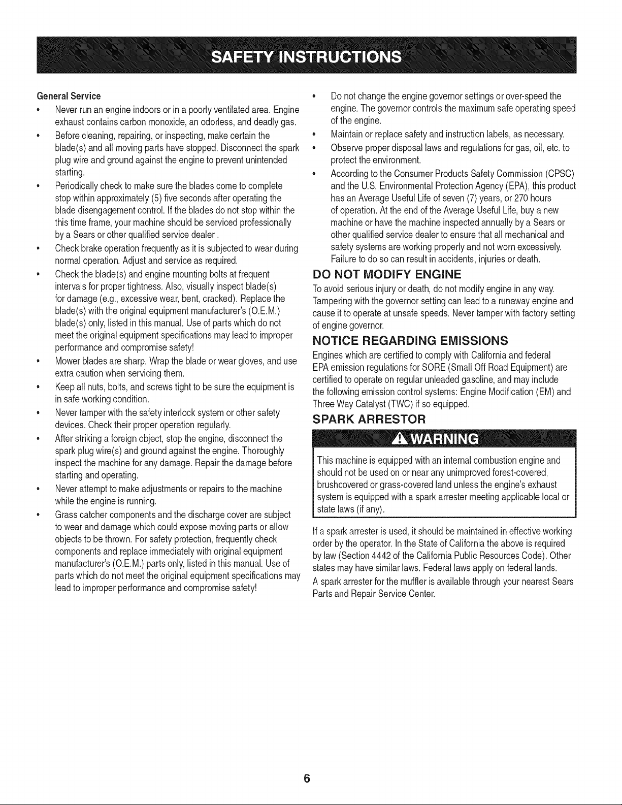
GeneralService
• Neverrunanengineindoorsorinapoorlyventilatedarea.Engine
exhaustcontainscarbonmonoxide,anodorless,anddeadlygas.
• Beforecleaning,repairing,orinspecting,makecertainthe
blade(s)andallmovingpartshavestopped.Disconnectthespark
plugwireandgroundagainsttheenginetopreventunintended
starting.
• Periodicallychecktomakesurethebladescometocomplete
stopwithinapproximately(5)fivesecondsafteroperatingthe
bladedisengagementcontrol.Ifthebladesdonotstopwithinthe
thistimeframe,yourmachineshouldbeservicedprofessionally
byaSearsorotherqualifiedservicedealer.
• Checkbrakeoperationfrequentlyasitissubjectedtowearduring
normaloperation.Adjustandserviceasrequired.
• Checktheblade(s)andenginemountingboltsatfrequent
intervalsforpropertightness.Also,visuallyinspectblade(s)
fordamage(e.g.,excessivewear,bent,cracked).Replacethe
blade(s)withtheoriginalequipmentmanufacturer's(O.E.M.)
blade(s)only,listedinthismanual.Useofpartswhichdonot
meettheoriginalequipmentspecificationsmayleadtoimproper
performanceandcompromisesafety!
• Mowerbladesaresharp.Wrapthebladeorweargloves,anduse
extracautionwhenservicingthem.
• Keepallnuts,bolts,andscrewstighttobesuretheequipmentis
insafeworkingcondition.
• Nevertamperwith the safetyinterlocksystemor othersafety
devices.Checktheir properoperationregularly.
• After strikinga foreignobject,stopthe engine,disconnectthe
sparkplugwire(s)and groundagainstthe engine.Thoroughly
inspectthe machinefor anydamage.Repairthe damagebefore
startingandoperating.
• Neverattemptto makeadjustmentsor repairsto the machine
whilethe engineis running.
• Grasscatchercomponentsand the dischargecoverare subject
to wearanddamagewhich couldexposemovingparts or allow
objectsto be thrown.Forsafetyprotection,frequentlycheck
componentsand replaceimmediatelywithoriginalequipment
manufacturer's(O.E.M.)partsonly,listed inthis manual.Use of
partswhichdo not meetthe originalequipmentspecificationsmay
leadto improperperformanceandcompromisesafety!
• Donot changethe enginegovernorsettingsorover-speedthe
engine.The governorcontrolsthe maximumsafe operatingspeed
of the engine.
Maintainor replacesafetyandinstructionlabels,as necessary.
• Observeproperdisposallaws andregulationsfor gas,oil, etc.to
protecttheenvironment.
• Accordingto the ConsumerProductsSafetyCommission(CPSC)
andthe U.S.EnvironmentalProtectionAgency(EPA),this product
has anAverageUsefulLifeof seven(7) years,or 270hours
of operation.At the end of the AverageUsefulLife,buy anew
machineor havethe machineinspectedannuallybya Searsor
otherqualifiedservicedealerto ensurethat all mechanicaland
safetysystemsare workingproperlyand not wornexcessively.
Failureto doso can resultin accidents,injuriesor death.
DO NOT MODIFY ENGINE
Toavoid seriousinjuryor death,do notmodifyenginein anyway.
Tamperingwiththe governorsettingcanlead to a runawayengineand
causeit to operateat unsafespeeds.Nevertamperwithfactorysetting
of enginegovernor.
NOTICE REGARDING EMISSIONS
Engineswhicharecertifiedto complywith Californiaand federal
EPAemissionregulationsfor SORE(SmallOffRoadEquipment)are
certifiedto operateon regularunleadedgasoline,andmay include
the followingemissioncontrol systems:EngineModification(EM)and
ThreeWayCatalyst(TWO)if so equipped.
SPARK ARRESTOR
Thismachineis equippedwithan internalcombustionengineand
shouldnotbe usedonor near anyunimprovedforest-covered,
brushcoveredor grass-coveredlandunlessthe engine'sexhaust
systemisequippedwith a sparkarrestermeetingapplicablelocalor
statelaws(if any).
Ifa sparkarresteris used,it shouldbe maintainedin effectiveworking
orderby the operator.Inthe Stateof Californiatheaboveis required
by law (Section4442of the CaliforniaPublicResourcesCode). Other
statesmayhavesimilarlaws.Federallaws applyonfederallands.
A sparkarresterfor the mufflerisavailablethroughyournearestSears
PartsandRepairServiceCenter.
6
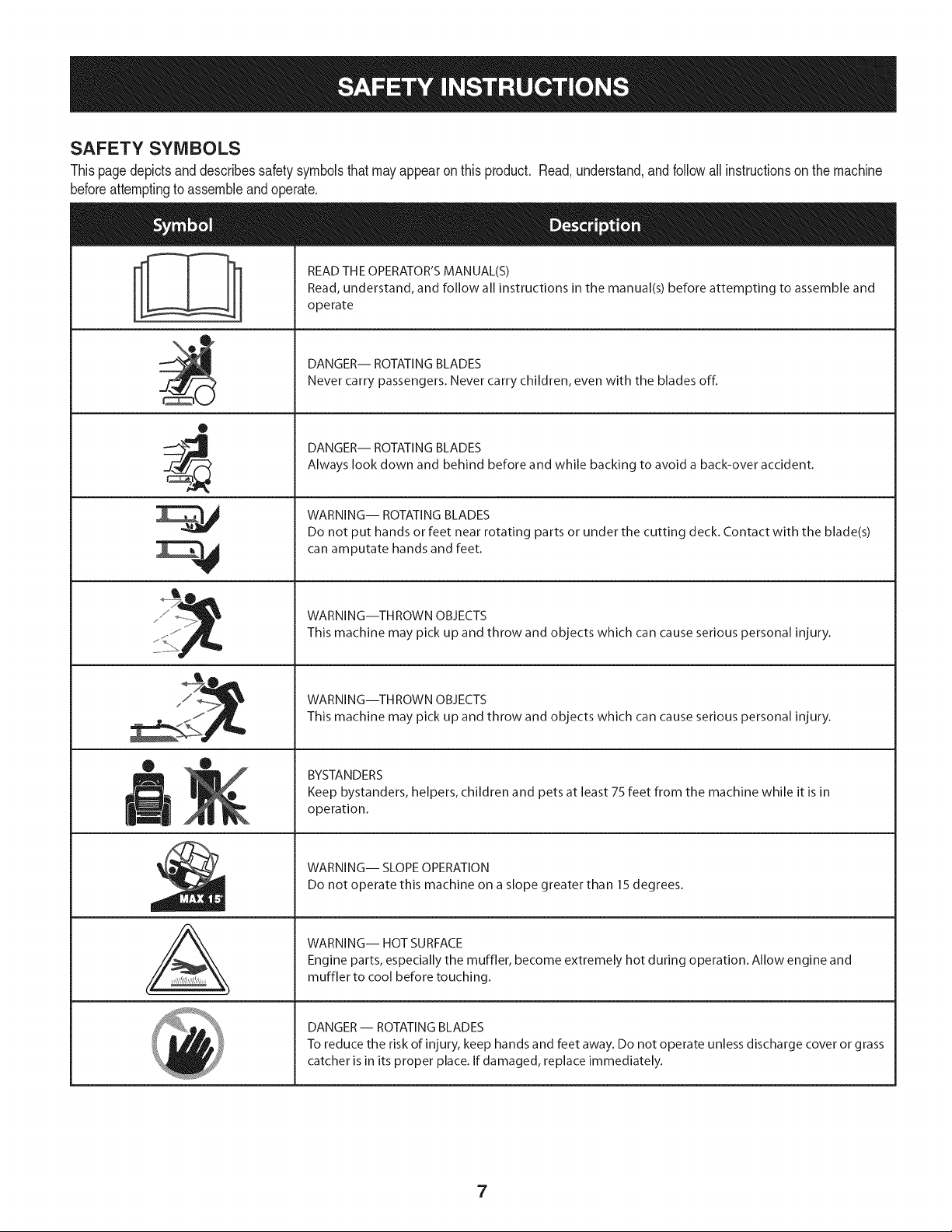
SAFETY SYMBOLS
Thispagedepictsanddescribessafety symbolsthatmayappearonthis product. Read,understand,andfollowall instructionson the machine
beforeattemptingto assembleandoperate.
0
A
READ THE OPERATOR'S MANUAL(S)
Read, understand, and follow all instructions in the manual(s) before attempting to assemble and
operate
DANGER-- ROTATING BLADES
Never carry passengers. Never carry children, even with the blades off.
DANGER-- ROTATING BLADES
Always look down and behind before and while backing to avoid a back-over accident.
WARNING-- ROTATING BLADES
Do not put hands or feet near rotating parts or under the cutting deck. Contact with the blade(s)
can amputate hands and feet.
WARNING--THROWN OBJECTS
This machine may pick up and throw and objects which can cause serious personal injury.
WARNING--THROWN OBJECTS
This machine may pick up and throw and objects which can cause serious personal injury.
BYSTANDERS
Keep bystanders, helpers, children and pets at least 75 feet from the machine while it is in
operation.
WARNING-- SLOPE OPERATION
Do not operate this machine on a slope greater than 15 degrees.
WARNING-- HOT SURFACE
Engine parts, especially the muffler, become extremely hot during operation. Allow engine and
muffler to cool before touching.
DANGER-- ROTATING BLADES
To reduce the risk of injury, keep hands and feet away. Do not operate unless discharge cover or grass
catcher is in its proper place. If damaged, replace immediately.
7
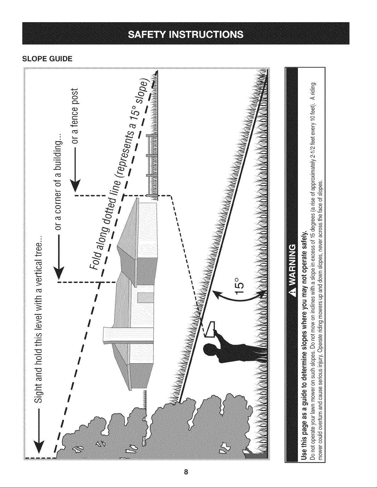
SLOPE GUIDE
}=.==
m
(=)
}====
G.)
1>
0_3
_==
(3)
OO
_==
C:)
_=
_==
0_3
=,F=_
03
_==
c_3
%,==,==
C)
}===
(1)
_==
}==,==
C)
(=3
c_3
}====
C)
_r
Or)
C;)
(=)
(==
CL)
%,==,=
c_3
}====
C)
_r
I
I
I
I
I
I
I
Dm m_
I
I
i
I
I
I
I
!
I
l
l
l
l
l
l
l
l
0
c
E
Q
8
o
(....
"'O
C3,
(1)
(1)
&
1>-.
03
E
x
o
cL (1)
03 cL
o co
"_--- (D
03 O
v_
_2
--_ o
cz o
03 "o
o
_E
(-" 03
o_
CZ3cL
o-_
_._o
o
8
WARNING
This symbol points out important safety instructions
which, if notfollowed, could endangerthe personal
safety and/or property of yourself and others. Readand
follow all instructions inthis manual before attempting
to operatethis machine. Failure to comply with these
instructions may result in personal injury.When you see
this symbol HEED ITS WARNING!
Your Responsibility
Restrictthe use of this power machine to persons who
read, understand, and follow the warnings and instruc-
tions in this manual and on the machine.
9
IMPORTANT:Yourtractoris shippedwith motoroil in theengine.
However,you MUSTcheckthe oil levelbeforeoperating.Referto the
Service& Maintenancesectionfor instructionson checkingtheoil
level.
Attaching the Battery Cables
CALIFORNIA PROPOSITION 65
Batteryposts,terminals,andrelatedaccessoriescontainlead and
leadcompounds,chemicalsknownto the Stateof Californiato
causecancerand reproductiveharm.Wash handsafter handling.
Whenattachingbatterycables,alwaysconnectthe POSITIVE(Red)
wireto its terminalfirst,followedby the NEGATIVE(Black)wire.
Forshippingreasons,bothbatterycableson yourequipmenthave
beenleft disconnectedfromthe terminalsat the factory.Toconnect
the batterycables,proceedas follows:
NOTE:Thepositivebatteryterminalis markedPos.(+).The negative
batteryterminalis markedNeg.(i).
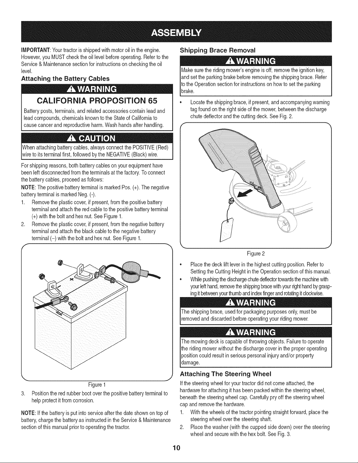
1. Removethe plasticcover,if present,fromthe positivebattery
terminaland attachthe redcableto the positivebatteryterminal
(+)withthe bolt andhexnut.See Figure1.
2. Removethe plasticcover,if present,fromthe negativebattery
terminaland attachthe blackcableto the negativebattery
terminal(-) withthe bolt andhex nut.SeeFigure1.
f
J
Figure1
3. Positionthe red rubberbootoverthe positivebatteryterminalto
helpprotectit fromcorrosion.
NOTE:If thebatteryis put into serviceafter the dateshownon topof
battery,chargethe batteryas instructedinthe Service& Maintenance
sectionof this manualpriorto operatingthe tractor.
Shipping Brace Removal
Makesurethe ridingmower'sengineis off, removetheignitionkey,
andset the parkingbrakebeforeremovingthe shippingbrace. Refer
Itothe Operationsectionfor instructionsonhowto set the parking
lbrake.
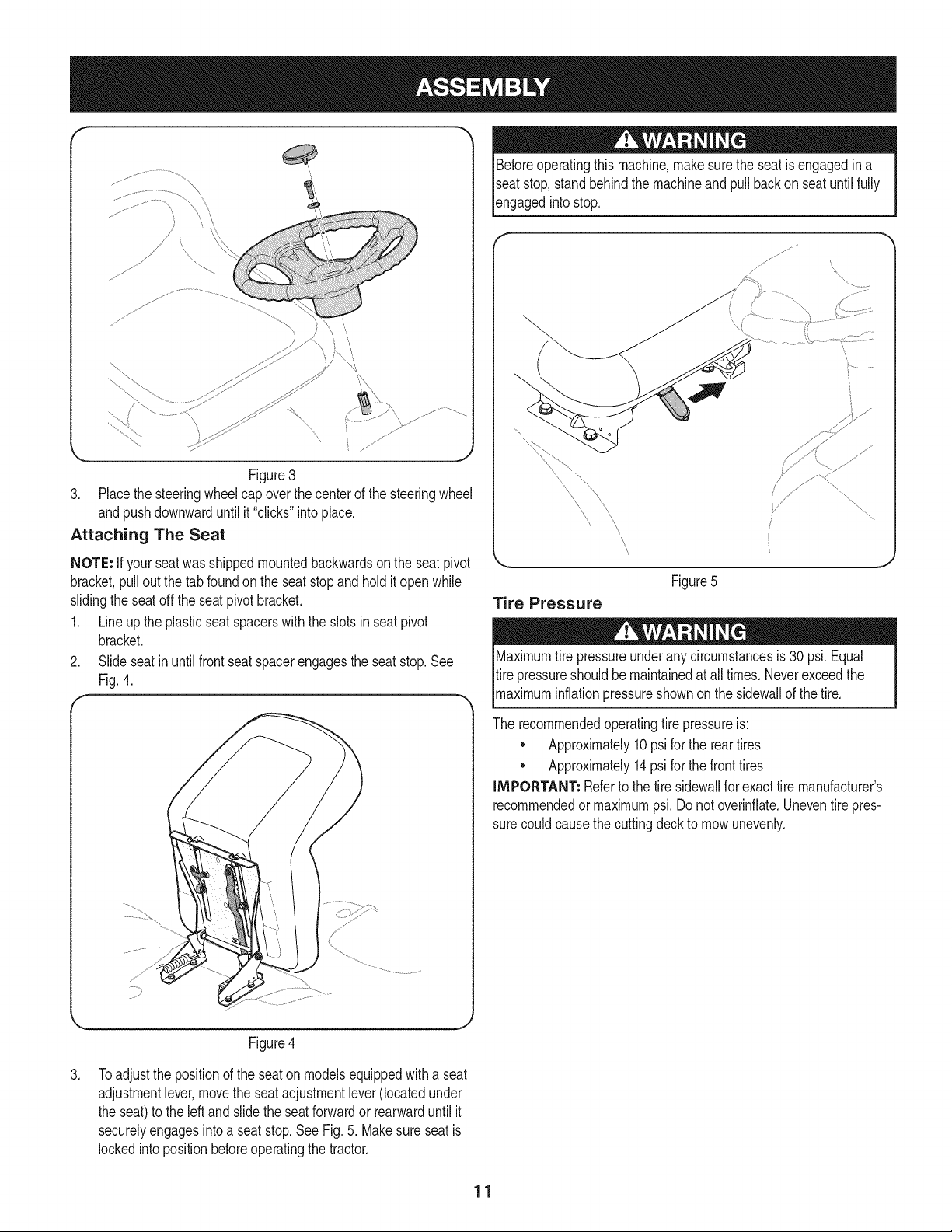
• Locatethe shippingbrace,if present,and accompanyingwarning
tag foundonthe rightsideof the mower,betweenthe discharge
chutedeflectorandthe cuttingdeck. SeeFig.2.
Figure2
Placethe deck lift leverin the highestcuttingposition.Referto
SettingtheCuttingHeightin the Operationsectionof this manual.
Whilepushingthedischargechuteddlectortowardsthemachinewith
yourlefthand,removetheshippingbracewithyourrighthandbygrasp-
ingitbetweenyourthumbandindexfingerandrotatingitclockwise.
The shippingbrace,usedfor packagingpurposesonly,mustbe
removedand discardedbeforeoperatingyour ridingmower.
The mowingdeck iscapableof throwingobjects.Failureto operate
the ridingmowerwithoutthe dischargecoverin the properoperating
Ipositioncould resultin seriouspersonalinjuryand/orproperty
ldamage.
Attaching The Steering Wheel
Ifthe steeringwheelfor yourtractordid notcome attached,the
hardwarefor attachingit has beenpackedwithinthe steeringwheel,
beneaththe steeringwheelcap. Carefullypry off the steeringwheel
cap andremovethe hardware.
1. Withthe wheelsof the tractorpointingstraightforward,placethe
steeringwheeloverthe steeringshaft.
2. Placethe washer(withthe cuppedside down) overthe steering
wheel andsecurewiththe hexbolt.SeeFig. 3.
10
f.-
\
Figure3
3. Placethe steeringwheelcap overthecenter of the steeringwheel
andpushdownwarduntilit "clicks"intoplace.
Attaching The Seat
NOTE: Ifyour seatwasshippedmountedbackwardsonthe seatpivot
bracket,pullout the tab foundonthe seatstopand hold it open while
slidingtheseatoff the seatpivotbracket.
1. Lineupthe plasticseatspacerswiththe slotsin seatpivot
bracket.
2. Slideseatin untilfrontseatspacerengagesthe seatstop.See
Fig.4.
Beforeoperatingthis machine,make surethe seat is engagedin a
seatstop,stand behindthe machineandpullback on seatuntil fully
_engagedntostop.
\
Figure5
Tire Pressure
Maximumtire pressureunderany circumstancesis 30 psi.Equal
tire pressureshouldbe maintainedat all times.Neverexceedthe
_maxmum nfat onpressureshownonthe s dewa of thet re.
The recommendedoperatingtire pressureis:
• Approximately10psi forthe reartires
• Approximately14psi forthe fronttires
IMPORTANT: Referto the tire sidewallfor exacttire manufacturer's
recommendedor maximumpsi.Donot overinfiate.Uneventirepres-
surecouldcausethe cuttingdeckto mowunevenly.
Figure4
.
Toadjustthe positionof the seatonmodelsequippedwitha seat
adjustmentlever,movethe seat adjustmentlever(locatedunder
the seat)to the leftand slidethe seatforwardor rearwarduntil it
securelyengagesintoa seatstop.See Fig.5. Makesure seat is
lockedinto positionbeforeoperatingthetractor.
11
B
f----It c
A
J
D
E
H
G
F
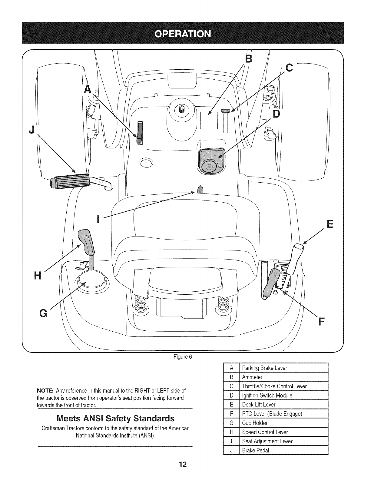
Figure6
NOTE: Any referencein this manualto the RIGHTor LEFTsideof
the tractoris observedfromoperator'sseat positionfacingforward
towardsthe front of tractor.
Meets ANSI Safety Standards
CraftsmanTractorsconformto the safetystandardof theAmerican
NationalStandardsInstitute(ANSI).
A ParkingBrakeLever
B Ammeter
C Throttle/ChokeControlLever
D IgnitionSwitchModule
E DeckLiftLever
F PTOLever(BladeEngage)
G Cup Holder
H SpeedControlLever
I SeatAdjustmentLever
J BrakePedal
12
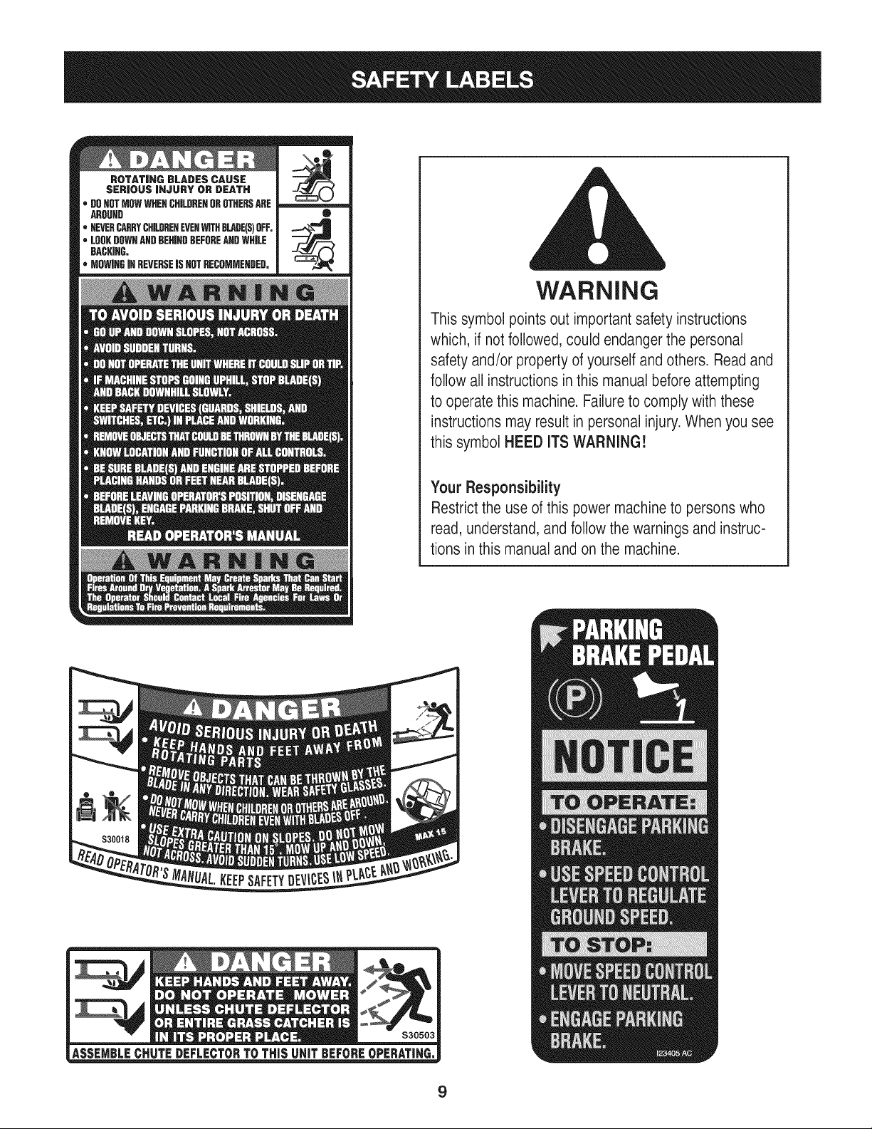
PARKING BRAKE
Tosetthe parkingbrake,fully depressthe parkingbrakepedal.Move
the parkingbrakeleverintothe ON position.Releasethe parkingbrake
pedalto allowthe parkingbraketo engage.
Toreleasethe parkingbrake,depressthe parkingbrakepedaland
movethe parkingbrakeleverout of the ONpositionandinto the OFF
position.
NOTE: The parkingbrakemustbe setif the operatorleavesthe seat
withthe enginerunningor the enginewill automaticallyshutoff.
AMMETER
Theammetermeasuresthe electricaloutput of the engine'scharging
system.Undernormaloperatingconditions,withengineat full throttle,
the ammetershouldindicatepositivecharge.
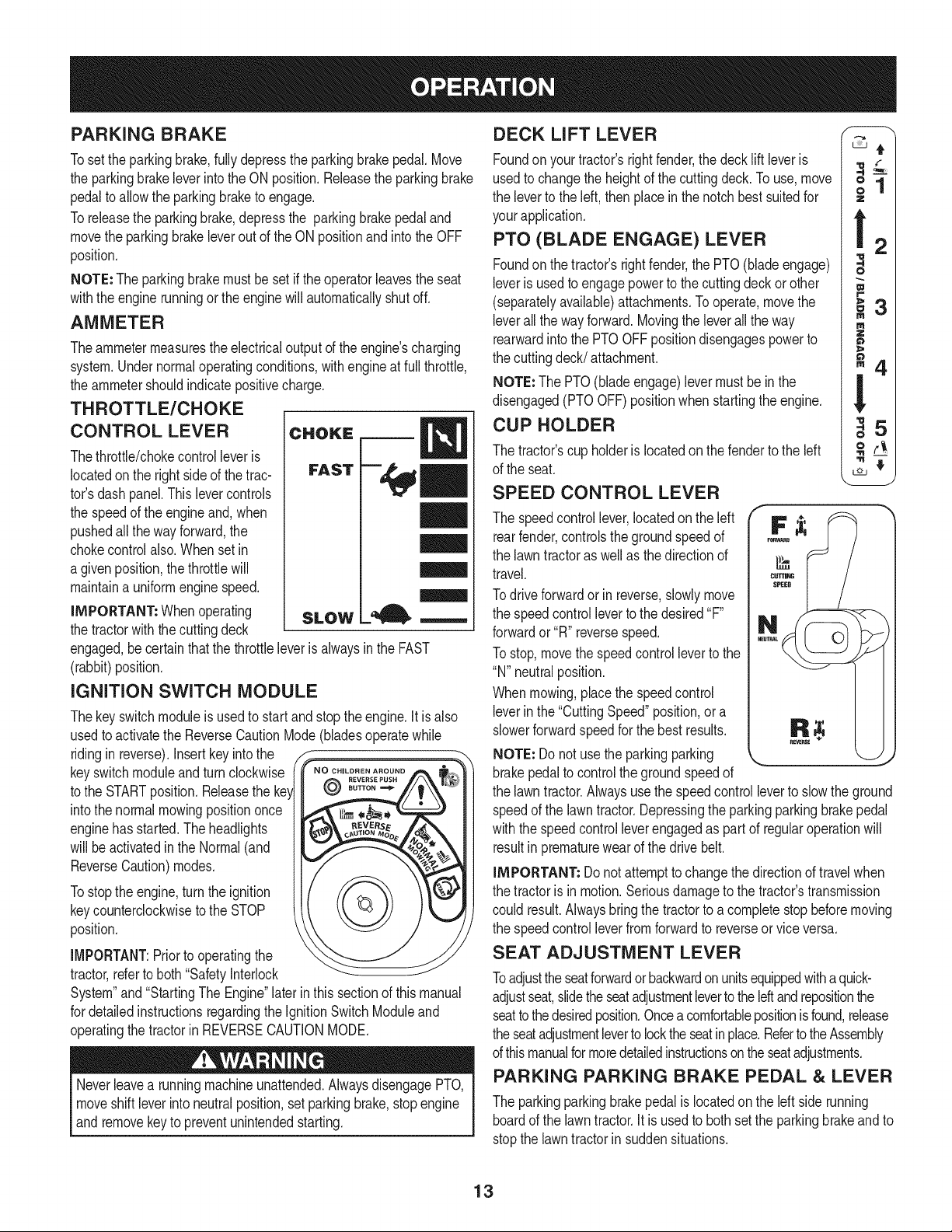
THROTTLE/CHOKE
CONTROL LEVER
Thethrottle/chokecontrolleveris
locatedonthe right sideof the trac-
tor'sdash panel.This levercontrols
the speedof the engineand, when
pushedall theway forward,the
chokecontrolalso.Whenset in
a givenposition,thethrottlewill
maintaina uniformenginespeed.
iMPORTANT: Whenoperating
the tractorwiththe cuttingdeck
CHOKE
FAST
SLOW
engaged,becertainthatthe throttleleveris alwaysin the FAST
(rabbit)position.
IGNITION SWITCH MODULE
Thekeyswitchmoduleis usedto start andstoptheengine.It is also
usedto activatethe ReverseCautionMode(bladesoperatewhile
ridingin reverse).Insertkey intothe _-
keyswitchmoduleandturn clockwise _Noo,,....... oo,o
to the STARTposition.Releasethe ke_ @
intothe normalmowingpositiononce
enginehas started.Theheadlights
will be activatedin the Normal(and
ReverseCaution)modes.
Tostopthe engine,turnthe ignition
keycounterclockwiseto the STOP
position.
IMPORTANT:Prior to operatingthe
tractor,referto both"Safetyinterlock
System"and"StartingThe Engine"later in this sectionof this manual
for detailedinstructionsregardingthe IgnitionSwitchModuleand
operatingthetractorin REVERSECAUTIONMODE.
Neverleavea runningmachineunattended.AlwaysdisengagePTO,
moveshift leverintoneutralposition,set parkingbrake,stopengine
andremovekeyto preventunintendedstarting.
DECK LIFT LEVER
Foundon your tractor'srightfender,the deck liftleveris
usedto changethe heightof the cuttingdeck. Touse,move
the leverto the left, thenplacein the notchbestsuitedfor
yourapplication.
PTO (BLADE ENGAGE) LEVER
Foundon the tractor'srightfender,the PTO(bladeengage)
leveris usedto engagepowerto the cuttingdeckorother
(separatelyavailable)attachments.Tooperate,movethe
leverall theway forward.Movingthe leverallthe way
rearwardinto the PTOOFFpositiondisengagespowerto
the cuttingdeck/attachment.
NOTE: The PTO(bladeengage)levermustbe in the
disengaged(PTOOFF)positionwhenstartingthe engine.
CUP HOLDER
The tractor'scup holderis locatedon the fenderto the left
of the seat.
SPEED CONTROL LEVER
Z
m
o
W
r =
m
"Zl.
m -
The speedcontrollever,locatedon the left IF
rearfender,controlsthe groundspeedof
the lawntractoras wellas the directionof
travel.
Todrive forwardor in reverse,slowlymove
the speedcontrolleverto the desired"F"
forwardor "R"reversespeed.
To stop,movethe speedcontrolleverto the
"N" neutralposition.
Whenmowing,placethe speedcontrol
leverin the "CuttingSpeed"position,or a
slowerforwardspeedfor the bestresults.
NOTE: Do not usethe parkingparking
brakepedal to controlthe groundspeedof
the lawntractor.Alwaysusethe speedcontrolleverto slow the ground
speedof the lawntractor.Depressingthe parkingparkingbrakepedal
withthe speedcontrolleverengagedas partof regularoperationwill
resultin prematurewearof the drivebelt.
iMPORTANT=Do notattemptto changethe directionof travelwhen
the tractoris in motion.Seriousdamageto thetractor'stransmission
could result.Alwaysbringthe tractorto a completestopbeforemoving
the speedcontrolleverfromforwardto reverseor viceversa.
SEAT ADJUSTMENT LEVER
Toadjusttheseatforwardor backwardonunitsequippedwithaquick-
adjustseat,slidethe seatadjustmentleverto theleftand repositionthe
seatto thedesiredposition.Onceacomfortablepositionisfound,release
the seatadjustmentleverto locktheseatinplace.Referto theAssembly
of thismanualformoredetailedinstructionson theseatadjustments.
PARKING PARKING BRAKE PEDAL & LEVER
The parkingparkingbrakepedalis locatedon the left side running
boardof the lawntractor.It is usedto bothset the parkingbrakeandto
stopthe lawntractorin suddensituations.
13
The parkingbrakeleveris locatedonthe leftside of the tractor'sdash
panel.To set the parkingbrake,fullydepressthe parkingparking
brakepedal.Movethe parkingbrakeleverall the waydownand into
the parkingbrakepositionand then releasethe parkingbrakepedalto
allowthe parkingbraketo engage.
To releasethe parkingbrake,depressthe parkingbrakepedalandthe
parkingbrakeleverwill automaticallymoveout of the parkingbrake
position.
In an suddensituation,fully depressthe parkingbrakepedalto bring
thetractorto a stopandthen immediatelymovethe speedcontrollever
to the "N" neutralposition
iMPORTANT: Donot usethe parkingparkingbrakepedalto control
thegroundspeedof the lawntractor.Doingso will resultin premature
wearof drivebelt. Alwaysuse the SpeedControlLeverto controlthe
groundspeedof the lawntractorandto stopthe tractorundernormal
circumstances.
NOTE: Theparkingparkingbrakepedalmustbe depressedto start
theengine.The parkingbrakemustalsobe set if the operatorleaves
the seatwiththe enginerunningor the enginewillautomaticallyshut
off. Referto SafetyInterlockSwitcheson page14.0il
iMPORTANT: Yourtractoris shippedwith motoroil in the engine.
However,you MUSTcheckthe oil levelbeforeoperating.Becareful
notto overfill.
Forinstructionson howto checkthe engineoil, referto CheckingThe
EngineOilin the ServiceandMaintenancesectionof this manual.
Gasoline
Thegasolinetank is locatedunderthe hood.Do notoverfill.
Useextremecarewhenhandlinggasoline.Gasolineis extremely
flammableandthe vaporsareexplosive.Neverfuel machineindoors
orwhilethe engineis hotor running.Extinguishcigarettes,cigars,
_ppes,and othersourcesof gn t on.
NOTE : Purchasegasolineinsmall quantities.Do notuse gasolineleft
overfromthe previousseason,to minimizegumdepositsin the fuel
system.
• This engineis certifiedto operateon unleadedgasoline.For best
results,fill the fueltank withonlyclean,fresh,unleadedgasoline
witha pumpstickeroctaneratingof 87or higher.
• Gasohol(upto 10%ethylalcohol,90% unleadedgasolineby
volume)is an approvedfuel.Othergasoline/alcoholblends,such
as E85,arenot approved.
• MethylTertiaryButylEther(MTBE)andunleadedgasolineblends
(upto a maximumof 15%MTBEby volume)are approvedfuels.
Othergasoline/etherblendsare notapproved.
• Fillfuel tankoutdoorsorin well-ventilatedarea.
• Do notoverfillfuel tank. Filltankto no morethan 1/2inch below
bottomof filler neckto allowspacefor fuel expansion.
• Neverremovegas capor add fuel whilethe engineis hot or run-
ning.Allowengineto cool at leasttwo minutesbeforerefueling.
• If gasolineis spilled,wipe it off theengineand equipment.Move
machineto anotherarea.Wait5 minutesbeforestartingthe
engine.
1. Turnthe engineoff and letenginecool at least2 minutesbefore
removingthe fuel cap.The gasolinetank is underthe hood,with
the fuel fill cap locatedon the left handsideof the tank.
2. Fillthe fueltankwithgasoline.
3. Reinstallthe fuel cap.
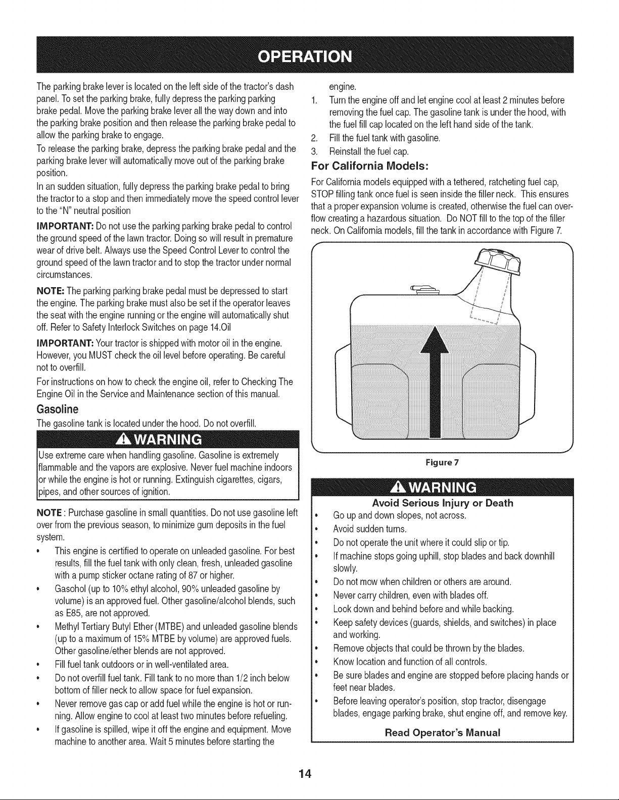
For California Models:
ForCaliforniamodelsequippedwitha tethered,ratchetingfuelcap,
STOPfillingtankoncefuel is seeninsidethe fillerneck. This ensures
thata properexpansionvolumeis created,otherwisethe fuelcan over-
flowcreatinga hazardoussituation. Do NOTfill to thetop of the filler
neck. OnCaliforniamodels,fill the tank in accordancewith Figure7.
Figure7
Avoid Serious Injury or Death
• Go up anddownslopes,notacross.
• Avoidsuddenturns.
• Donot operatethe unitwhereitcould slipor tip.
• If machinestopsgoing uphill,stopbladesand backdownhill
slowly.
• Donot mowwhenchildrenorothersare around.
• Nevercarry children,evenwith bladesoff.
• Lookdownand behindbeforeand whilebacking.
• Keepsafetydevices(guards,shields,and switches)inplace
andworking.
• Removeobjectsthat couldbethrownby the blades.
• Knowlocationandfunctionof all controls.
• Be surebladesand enginearestoppedbeforeplacinghandsor
feetnear blades.
• Beforeleavingoperator'sposition,stop tractor,disengage
blades,engageparkingbrake,shutengineoff, and removekey.
Read Operator's Manual
14
SAFETY iNTERLOCK SYSTEM
Thesafetyinterlocksystemisdesignedfor safe operationof thetrac-
tor.Ifthis systemshouldever malfunction,do not operatethe tractor,
immediatelycontact1-800-4-MY-HOMEto havethe systemserviced.
• Thesafety interlocksystempreventsthe engine fromstarting
unlessthe parkingbrakeis engagedandthe PTO(BladeEngage)
leveris in thedisengaged(OFF)position.
Thesafetyinterlocksystemwill automaticallyshutoff the engine if
the operatorleavesthe seat beforeengagingthe parkingbrake.
Thesafetyinterlocksystemwill automaticallyshutoff the engine
ifthe operatorleavesthe tractor'sseat with the PTO(Blade
Engage)leverengaged,regardlessof whetherthe parkingbrake
is engaged.
REVERSE CAUTION MODE
Useextremecautionwhileoperatingthetractorin the REVERSE
CAUTIONMODE.Alwayslookdownand behindbeforeand while
backing.Do notoperatethe tractorwhenchildrenor othersare
around.Stopthe tractorimmediatelyif someoneentersthe area.
The REVERSECAUTIONMODEpositionof the key switchmodule
allowsthe tractorto be operatedin reversewiththe blades(PTO)
engaged.
IMPORTANT: Mowingin reverseis not recommended.
Touse the REVERSECAUTIONMODE:
IMPORTANT: The operatorMUSTbeseatedinthe tractorseat.
1. Startengineas instructedunderthe heading StartingTheEngine.
2. Turnthe keyfromthe NORMALMO%NG (Green)positionto the
REVERSECAUTIONMODE(Yellow)positionof the keyswitch
module.SeeFigure8.
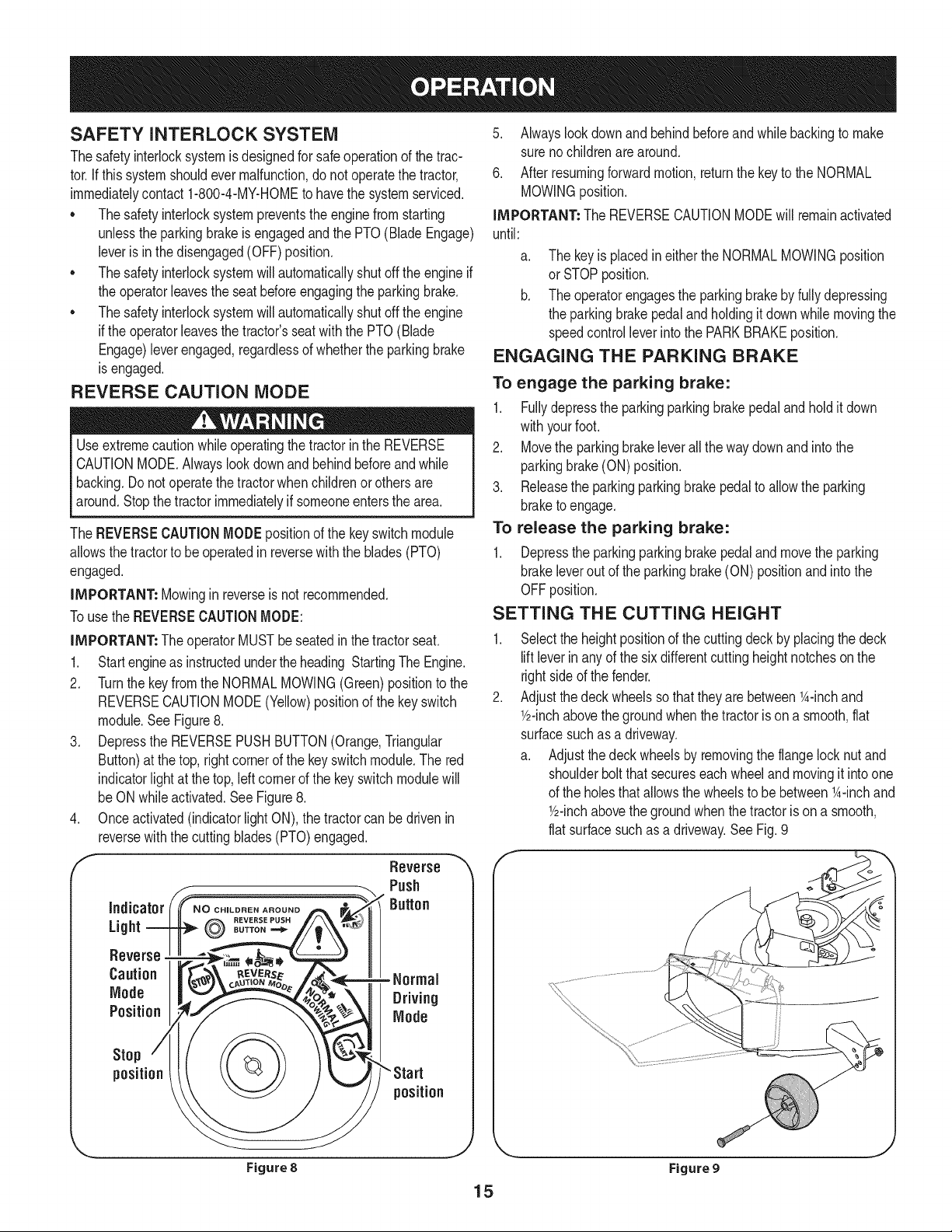
3. Depressthe REVERSEPUSHBUTTON(Orange,Triangular
Button)at the top, rightcornerof the keyswitchmodule.The red
indicatorlight at the top, leftcornerof the key switchmodulewill
beON whileactivated.See Figure8.
4. Onceactivated(indicatorlightON), the tractorcan bedrivenin
reversewith the cuttingblades(PTO)engaged.
f
Indicator
Light
Reverse
Caution
Mode
Position
Reverse "_
Push
Button
- Normal
Driving
Mode
Stop
position
position
Figure 8
J
5. Alwayslookdownandbehindbeforeandwhile backingto make
surenochildrenarearound.
6. Afterresumingforwardmotion,returnthe keyto the NORMAL
MOWINGposition.
iMPORTANT: The REVERSECAUTIONMODEwill remainactivated
until:
a.
The keyis placedineitherthe NORMALMOWINGposition
or STOPposition.
b. The operatorengagesthe parkingbrakeby fullydepressing
the parkingbrakepedalandholdingit downwhile movingthe
speedcontrolleverinto the PARKBRAKEposition.
ENGAGING THE PARKING BRAKE
To engage the parking brake:
1. Fullydepressthe parkingparkingbrakepedal andholditdown
withyourfoot.
2. Movethe parkingbrakeleverall the waydownand intothe
parkingbrake(ON)position.
3. Releasethe parkingparkingbrakepedal to allowthe parking
braketo engage.
To release the parking brake:
1. Depressthe parkingparkingbrakepedaland movethe parking
brakeleverout of the parkingbrake(ON) positionand intothe
OFFposition.
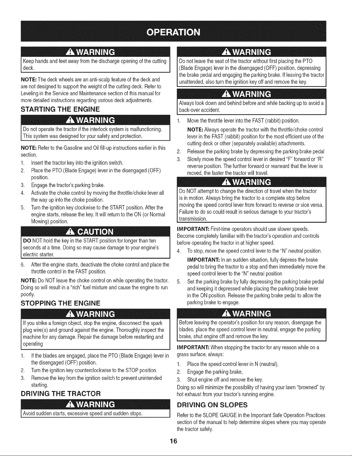
SETTING THE CUTTING HEIGHT
Selectthe heightpositionof the cuttingdeck by placingthe deck
liftleverinanyof the sixdifferentcutting heightnotchesonthe
rightsideof the fender.
Adjustthedeck wheelsso that theyarebetween1A-inchand
Y2-inchabovethe groundwhenthe tractoris ona smooth,flat
surfacesuch as a driveway.
a. Adjustthedeckwheelsby removingthe flangelocknut and
shoulderboltthat secureseachwheeland movingit intoone
of the holesthat allowsthe wheelsto be between_A-inchand
Y2-inchabovethe groundwhenthe tractoris ona smooth,
flat surfacesuch as a driveway.SeeFig.9
Figure 9
15
Keephandsandfeet awayfromthedischargeopeningof thecutting
deck.
NOTE=The deckwheelsarean anti-scalpfeatureof the deckand
arenot designedto supportthe weightof the cuttingdeck. Referto
Levelingin the Serviceand Maintenancesectionof thismanualfor
moredetailedinstructionsregardingvariousdeckadjustments.
STARTING THE ENGINE
Donot leavethe seatof the tractorwithoutfirst placingthe PTO
(BladeEngage)leverin the disengaged(OFF)position,depressing
the brakepedalandengagingthe parkingbrake.If leavingthe tractor
unattended,also turnthe ignitionkeyoff andremovethe key.
Alwayslook downandbehindbeforeandwhile backingupto avoida
back-overaccident.
Do notoperatethe tractorif the interlocksystemis malfunctioning.
Thissystemwasdesignedfor your safetyandprotection.
NOTE=Referto the Gasolineand Oilfill-upinstructionsearlierinthis
section.
1. Insertthe tractorkey intothe ignitionswitch.
2. Placethe PTO(BladeEngage)leverin the disengaged(OFF)
position.
3. Engagethe tractor'sparkingbrake.
4. Activatethe chokecontrolby movingthe throttle/chokeleverall
thewayup intothe chokeposition.
5. Turnthe ignitionkeyclockwiseto the STARTposition.After the
enginestarts,releasethe key.It will returnto the ON (orNormal
Mowing)position.
DO NOTholdthe key in the STARTpositionfor longerthanten
secondsat a time.Doingso maycausedamageto yourengine's
electricstarter.
6. Afterthe engine starts,deactivatethe chokecontroland placethe
throttlecontrolinthe FASTposition.
NOTE=Do NOTleavethechokecontrol onwhileoperatingthe tractor.
Doingso will resultin a "rich" fuel mixtureandcausethe engineto run
poorly.
STOPPING THE ENGINE
If youstrikea foreignobject,stop the engine,disconnectthe spark
plugwire(s)andgroundagainstthe engine.Thoroughlyinspectthe
machinefor anydamage.Repairthe damagebeforerestartingand
operating
1. Ifthe bladesareengaged,placethe PTO(Blade Engage)leverin
thedisengaged(OFF) position.
2. Turnthe ignitionkeycounterclockwiseto the STOPposition.
3. Removethe keyfromthe ignitionswitchto preventunintended
starting.
DRIVING THE TRACTOR
Avoidsuddenstarts,excessivespeedand suddenstops.
1. Movethethrottleleverintothe FAST(rabbit)position.
NOTE=Alwaysoperatethe tractorwiththethrottle/chokecontrol
leverin the FAST(rabbit) positionfor the mostefficientuseof the
cuttingdeckor other(separatelyavailable)attachments.
2. Releasethe parkingbrakeby depressingthe parkingbrakepedal
3. Slowlymovethe speedcontrol leverin desired"F" forwardor "R"
reverseposition.Thefurtherforwardor rearwardthatthe leveris
moved,the fasterthe tractorwill travel.
DoNOTattemptto changethe directionof travel whenthe tractor
is inmotion.Alwaysbringthe tractorto a completestopbefore
movingthe speedcontrol leverfromforwardto reverseorvice versa.
Failureto doso couldresultinseriousdamageto yourtractor's
transmission.
IMPORTANT: First-timeoperatorsshoulduseslowerspeeds.
Becomecompletelyfamiliarwiththetractor'soperationandcontrols
beforeoperatingthetractorin at higherspeed.
4. To stop,movethe speedcontrolleverto the "N" neutralposition.
IMPORTANT: in an suddensituation,fullydepressthe brake
pedalto bringthetractorto a stopandthen immediatelymovethe
speedcontrolleverto the "N" neutralposition
5. Set the parkingbrakeby fully depressingthe parkingbrakepedal
and keepingit depressedwhileplacingthe parkingbrakelever
in the ON position.Releasethe parkingbrakepedal to allowthe
parkingbraketo engage.
Beforeleavingthe operator'spositionfor any reason,disengagethe
blades,placethe speedcontrolleverin neutral,engagethe parking
brake,shutengineoff and removethe key.
IMPORTANT=Whenstoppingthe tractorforany reasonwhile on a
grasssurface,always:
1. Placethe speedcontrolleverin N (neutral),
2. Engagethe parkingbrake,
3. Shutengineoffand removethe key.
Doingso will minimizethe possibilityof havingyour lawn"browned"by
hot exhaustfrom yourtractor'srunningengine.
DRIVING ON SLOPES
Referto the SLOPEGAUGEin the ImportantSafeOperationPractices
sectionof the manualto help determineslopeswhereyou mayoperate
the tractorsafely.
16
Do notmow on inclineswith a slopein excessof 15 degrees(a rise
of approximately2-1/2feetevery10feet). Thetractorcouldoverturn
andcauseseriousinjury.
• Mow upanddownslopes,NEVERacross.
Exerciseextremecautionwhenchangingdirectionon slopes.
Watchfor holes,ruts,bumps,rocks,or otherhiddenobjects.
Uneventerraincouldoverturnthemachine.Tallgrasscan hide
obstacles.
Avoidturns whendrivingona slope. Ifa turn mustbemade,turn
downthe slope.Turningup a slopegreatlyincreasesthechance
of a roll over.
Avoidstoppingwhendrivingup a slope.Ifit is necessaryto stop
whiledrivingupa slope,start up smoothlyand carefullyto reduce
the possibilityof flippingthe tractoroverbackward.
ENGAGING THE BLADES
Engagingthe PTO(BladeEngage)transferspowerto the cuttingdeck
orother (separatelyavailable)attachments.Toengagethe blades,
proceedas follows:
1. Movethe throttle/chokecontrol leverto the FAST(rabbit)position.
2. Graspthe PTO(BladeEngage)leverandpivot it all the way
forwardintothe engaged(ON)position.
3. Keepthe throttleleverin the FAST(rabbit)positionforthe most
efficientuseof thecuttingdeckor other(separatelyavailable)
attachments.
IMPORTANT: Inthe ReverseCautionModethe enginewillauto-
maticallyshut off ifthe PTOisengagedwith the speedcontrollever
inpositionfor reversetravelwith the ignitionkeyin the NORMAL
MOWINGposition.
USING THE DECK LIFT LEVER
Toraisethe cuttingdeck,movethe deck lift levertothe left,then place
itin the notchbestsuitedfor yourapplication.Referto SettingThe
CuttingHeightearlierinthis section.
MOWING
Tohelpavoidbladecontactor a thrownobjectinjury,keepbystand-
ers,helpers,childrenandpetsat least75 feetfromthe machine
whileit is in operation.Stop machineif anyoneentersthearea.
for the balanceof cutting.This will givea betterappearanceto the
lawn.
• Donot cutthe grasstoo short. Shortgrassinvitesweedgrowth
andyellowsquicklyin dry weather.
• Mowingshouldalwaysbedone withthe engineat full throttle.
• Underheavierconditionsit maybe necessaryto go backoverthe
cut areaa secondtimeto get a cleancut.
• Do NOTattemptto mowheavy brushandweedsandextremely
tall grass.Yourtractorisdesignedto mowlawns,NOTclear
brush.
• Keepthe bladessharpand replacethe bladeswhenworn. Refer
to CuttingBladesin the Serviceand Maintenencesectionof this
manualfor properbladesharpeninginstructions.
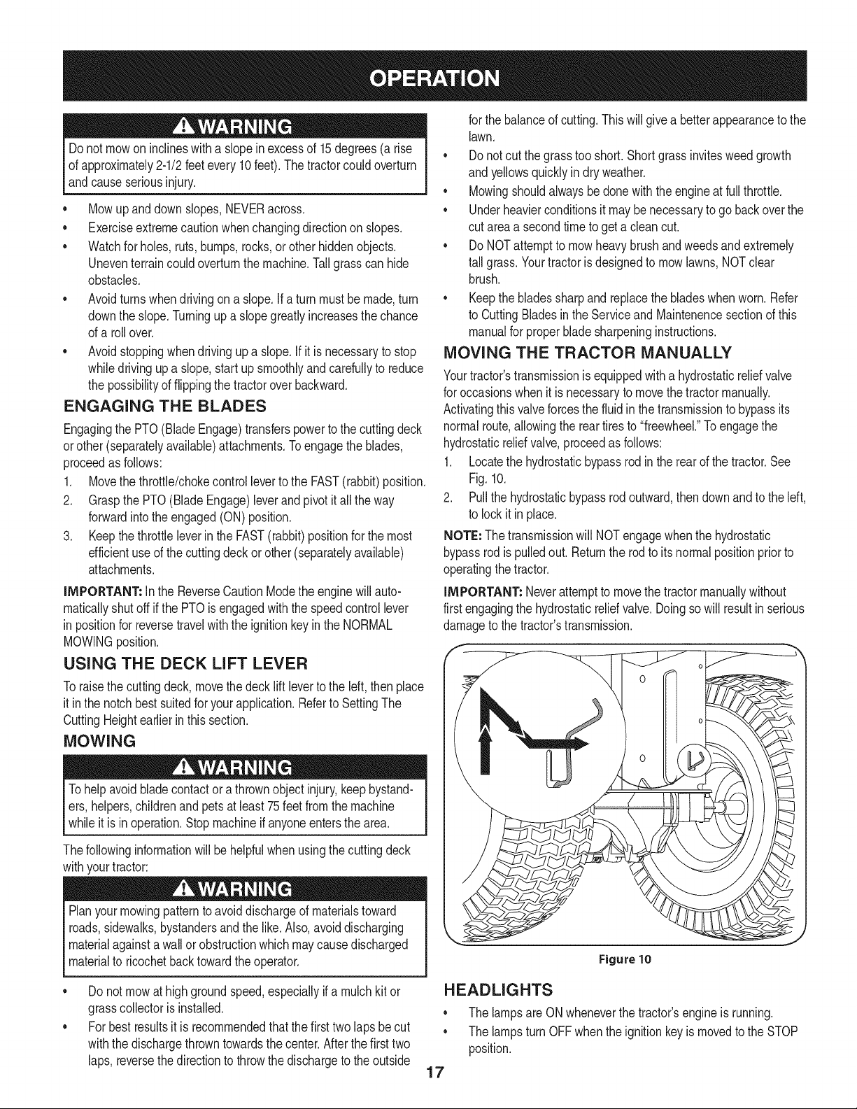
MOVING THE TRACTOR MANUALLY
Yourtractor'stransmissionis equippedwitha hydrostaticreliefvalve
for occasionswhen it isnecessaryto movethetractormanually.
Activatingthis valveforcesthe fluid inthetransmissionto bypassits
normalroute,allowingthe reartiresto "freewheel."To engagethe
hydrostaticreliefvalve,proceedas follows:
1. Locatethe hydrostaticbypassrodinthe rearof the tractor.See
Fig.10.
2. Pullthe hydrostaticbypassrodoutward,thendownandto the left,
to lockitinplace.
NOTE: Thetransmissionwill NOTengagewhenthe hydrostatic
bypassrod ispulledout. Returnthe rodto itsnormalpositionprior to
operatingthe tractor.
IMPORTANT: Neverattemptto movethe tractormanuallywithout
first engagingthe hydrostaticreliefvalve.Doingso will resultinserious
damageto thetractor'stransmission.
Thefollowinginformationwill be helpfulwhenusingthe cuttingdeck
withyourtractor:
Planyour mowingpatternto avoiddischargeof materialstoward
roads,sidewalks,bystandersand the like.Also, avoiddischarging
materialagainsta wallor obstructionwhichmaycausedischarged
materialto ricochetbacktowardthe operator.
Figure 10
Do not mowat highgroundspeed,especiallyif a mulch kitor
grasscollectoris installed.
For best resultsit is recommendedthat the firsttwo laps be cut
withthe dischargethrowntowardsthe center.Afterthe first two
laps,reversethe directionto throwthe dischargeto the outside
HEADLIGHTS
• The lampsare ONwheneverthe tractor'sengineis running.
• The lampsturn OFFwhenthe ignitionkeyis movedto the STOP
position.
17
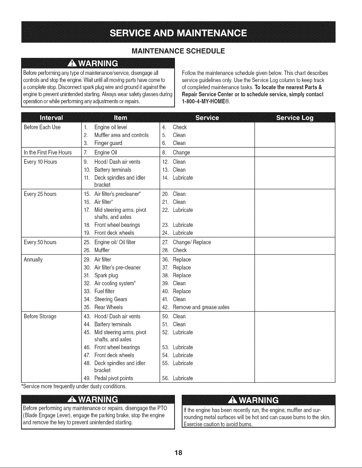
MAINTENANCE SCHEDULE
Beforeperforminganytypeof maintenance/service,disengageall
controlsand stoptheengine.Waituntilallmovingpartshavecometo
acompletestop.Disconnectsparkplugwireandgrounditagainstthe
enginetopreventunintendedstarting.Alwayswearsafetyglassesduring
operationor whileperforminganyadjustmentsor repairs.
Followthe maintenanceschedulegivenbelow.This chartdescribes
serviceguidelinesonly. Usethe ServiceLogcolumnto keeptrack
of completedmaintenancetasks.To locate the nearest Parts &
Repair Service Centeror to scheduleservice,simplycontact
1-800-4-MY-HOME®.
BeforeEachUse
In the FirstFive Hours
Every10Hours
Every25 hours
Every50 hours
Annually
BeforeStorage
1. Engineoil level
2. Mufflerareaandcontrols
3. Fingerguard
7. EngineOil
9. Hood/Dashair vents
10. Batteryterminals
11. Deckspindlesand idler
bracket
15. Air filter'sprecleaner*
16. Air filter*
17. Midsteeringarms,pivot
shafts,and axles
18. Frontwheelbearings
19. Frontdeck wheels
25. Engineoil/Oil filter
26. Muffler
29. Air filter
30. Air filter'spre-cleaner
31. Sparkplug
32. Air coolingsystem*
33. Fuelfilter
34. SteeringGears
35. RearWheels
43. Hood/Dash airvents
44. Batteryterminals
45. Midsteeringarms,pivot
shafts,and axles
46. Frontwheelbearings
47. Frontdeck wheels
48. Deckspindlesand idler
bracket
49. Pedalpivot points
4. Check
5. Clean
6. Clean
8. Change
12. Clean
13. Clean
14. Lubricate
20. Clean
21. Clean
22. Lubricate
23. Lubricate
24. Lubricate
27. Change/Replace
28. Check
36. Replace
37. Replace
38. Replace
39. Clean
40. Replace
41. Clean
42. Removeandgreaseaxles
50. Clean
51. Clean
52. Lubricate
53. Lubricate
54. Lubricate
55. Lubricate
56. Lubricate
*Servicemorefrequentlyunderdustyconditions.
Beforeperformingany maintenanceor repairs,disengagethe PTO
(BladeEngageLever),engagethe parkingbrake,stopthe engine
and removethe keyto preventunintendedstarting.
Ifthe enginehasbeen recentlyrun,the engine,mufflerandsur-
roundingmetalsurfaceswill behotand cancause burnsto the skin.
Exercisecautionto avoidburns.
18
ENGINE MAINTENANCE
Checking the Engine Oil
Onlyuse highqualitydetergentoil ratedwith APIserviceclassification
SF,SG,SH,or SJ, Selectthe oil's SAEviscositygradeaccordingto
the expectedoperatingtemperature.Followthe chartbelow.
Althoughmulti-viscosityoils (5W20,10W30,etc.)improvestarting
in coldweather,theywill resultinincreasedoil consumptionwhen
usedabove32°E Checkyour engineoillevelmorefrequentlyto avoid
possibleenginedamagefromrunninglowonoil.
('_older _ 32°F _War me'_r
Oil Viscosity Chart
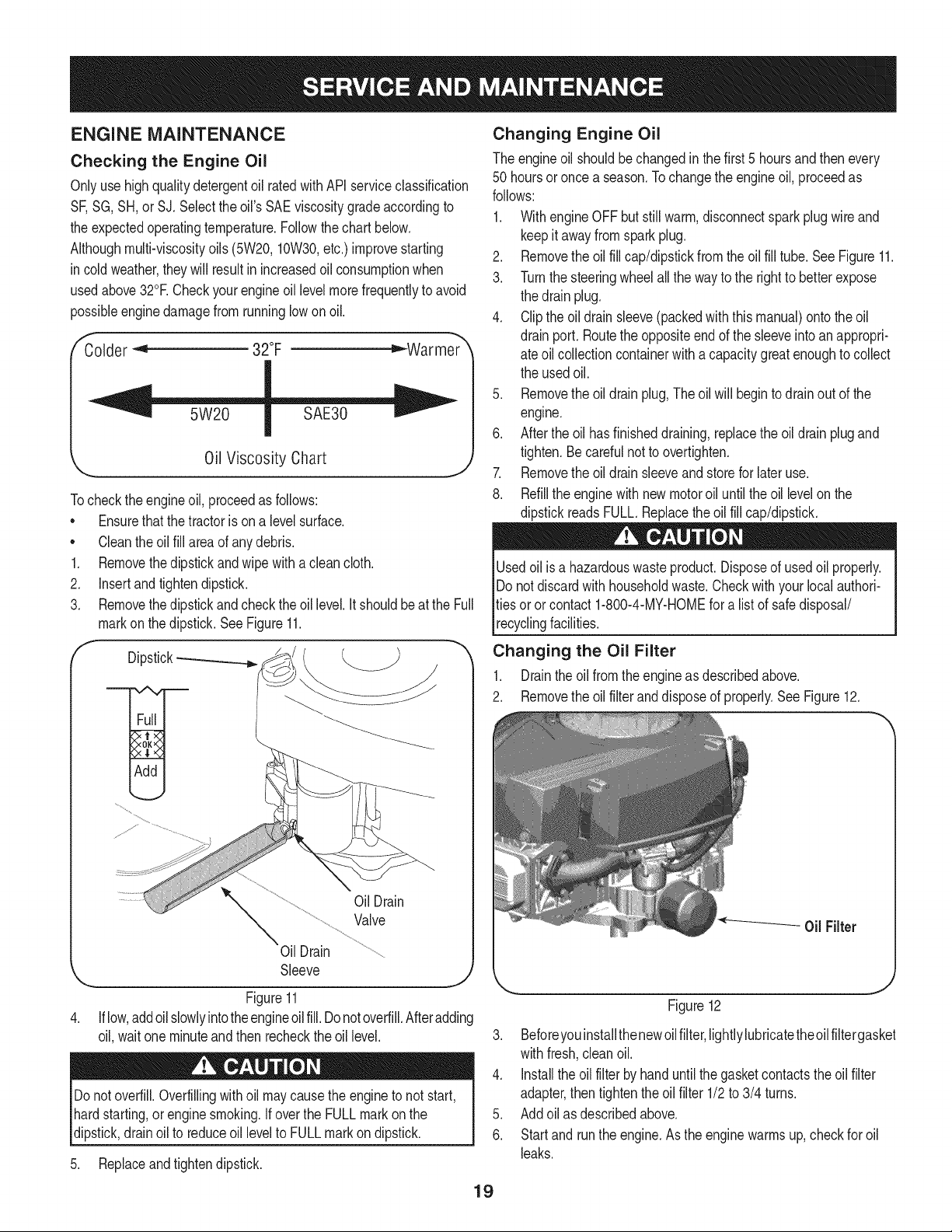
Tocheckthe engineoil, proceedas follows:
• Ensurethatthe tractoris on a levelsurface.
• Cleantheoil fill areaof anydebris.
1. Removethedipstickand wipe with aclean cloth.
2. Insertandtightendipstick.
3. Removethe dipstickand checktheoil level.It shouldbeatthe Full
markon thedipstick.SeeFigure11.
f
Dipstick-_
OilDrain
Valve
Oil Drain
Sleeve
J
Figure11
Iflow,addoilslowlyintotheengineoil fill.Donotoverfill.Afteradding
oil, waitone minuteandthen recheckthe oil level.
Donotoverfill.Overfillingwith oil maycausethe engine to not start,
hardstarting,or enginesmoking.If overthe FULLmarkon the
dipstick,drain oil to reduceoil levelto FULLmarkondipstick.
5. Replaceandtightendipstick.
Changing Engine Oil
The engineoil shouldbe changedinthe first 5 hoursand thenevery
50 hoursoronce a season.Tochangethe engineoil, proceedas
follows:
1. WithengineOFFbut stillwarm,disconnectsparkplugwireand
keepit awayfrom sparkplug.
2. Removethe oil fill cap/dipstickfrom theoil fill tube. SeeFigure11.
3. Turnthe steeringwheelallthe wayto the rightto betterexpose
the drainplug.
4. Clipthe oildrainsleeve(packedwiththis manual)ontothe oil
drainport. Routethe oppositeend of the sleeveintoanappropri-
ate oil collectioncontainerwith a capacitygreatenoughto collect
the usedoil.
5. Removethe oil drainplug,The oilwill begintodrainout of the
engine.
6. Afterthe oil hasfinisheddraining,replacethe oil drainplugand
tighten.Becarefulnot to overtighten.
7. Removethe oil drainsleeveandstorefor later use.
8. Refillthe enginewithnewmotoroil untilthe oil levelonthe
dipstickreadsFULL.Replacetheoil fill cap/dipstick.
Usedoil is a hazardouswasteproduct.Disposeof usedoil properly.
Do notdiscardwithhouseholdwaste.Checkwith your localauthori-
ties oror contact 1-800-4-MY-HOMEfor a list of safedisposal/
recyclingfacilities.
Changing the Oil Filter
1. Drainthe oil fromthe engineas describedabove.
2. Removethe oil filteranddisposeof properly.See Figure12.
0il Filter
Figure12
3. Beforeyouinstallthenewoilfilter,lightlylubricatetheoilfiltergasket
withfresh,cleanoil.
4. Installthe oil filter byhanduntilthe gasketcontactstheoil filter
adapter,then tightenthe oilfilter 1/2to 3/4 turns.
5. Addoil as describedabove.
6. Startand runthe engine.Asthe enginewarmsup,checkfor oil
leaks.
19
7. Stopthe engineand checkthe oil level.It shouldbe at the FULL
markon the dipstick.
Fuel Filter
31osioncan causesevereburnsor death.
4. Securethefuel lineswith the clamps.
Iffilters,or coversare notinstalledcorrectlyseriousinjuryordeath
could resultfrombackfire.Do notattemptto startthe enginewith
themremoved.
• Keepgasolineawayfromsparks,openflames,pilotlights,heat,
andotherignitionsources.
• Checkfuel lines, tank,cap,andfittingsfrequentlyforcracksor
leaks.Replaceif necessary.
• Beforereplacingthe fuelfilter,drainthe fueltankas perthe
instructionsbelow.
• Do notdrainfuel whenthe engineis hot.Allowthe engine
adequatetimeto cool. Drainfuel intoan approvedcontainer
outdoors,awayfromopenflame.
• Drainanylarge volumeof fuelfrom the tank by disconnectingthe
fuel linefromthe in-linefuelfilternear theengine.
• Removethe fuel line fromthe In-lineside (sidetowardsthe fuel
tank)of thefuel filter.
• Replacementparts mustbethe sameand installedin the same
positionas theoriginalparts.
• If fuel spills,wait until it evaporatesbeforestartingengine.
• Beforereplacingthe fuelfilter,drainthe fueltank. Otherwisefuel
can leakout and causea fireor explosion.
ToDrainthe fuel:
1. Locatethefuelfilter,whichis routedonthe leftsideofthe eng=ne
betweenthe fueltankandthe carburetor,andmaybeattachedto
theenginewitha tie strap.Cutthetie strap,if present,then pinch
thein-lineclamponthefuelfilterwith a pairof pliers,slidethe
clampupthefuelline.Pullthe fuellinefreefromthefilterandplace
theopenendof the lineintoan approvedcontainerto drainthefuel.
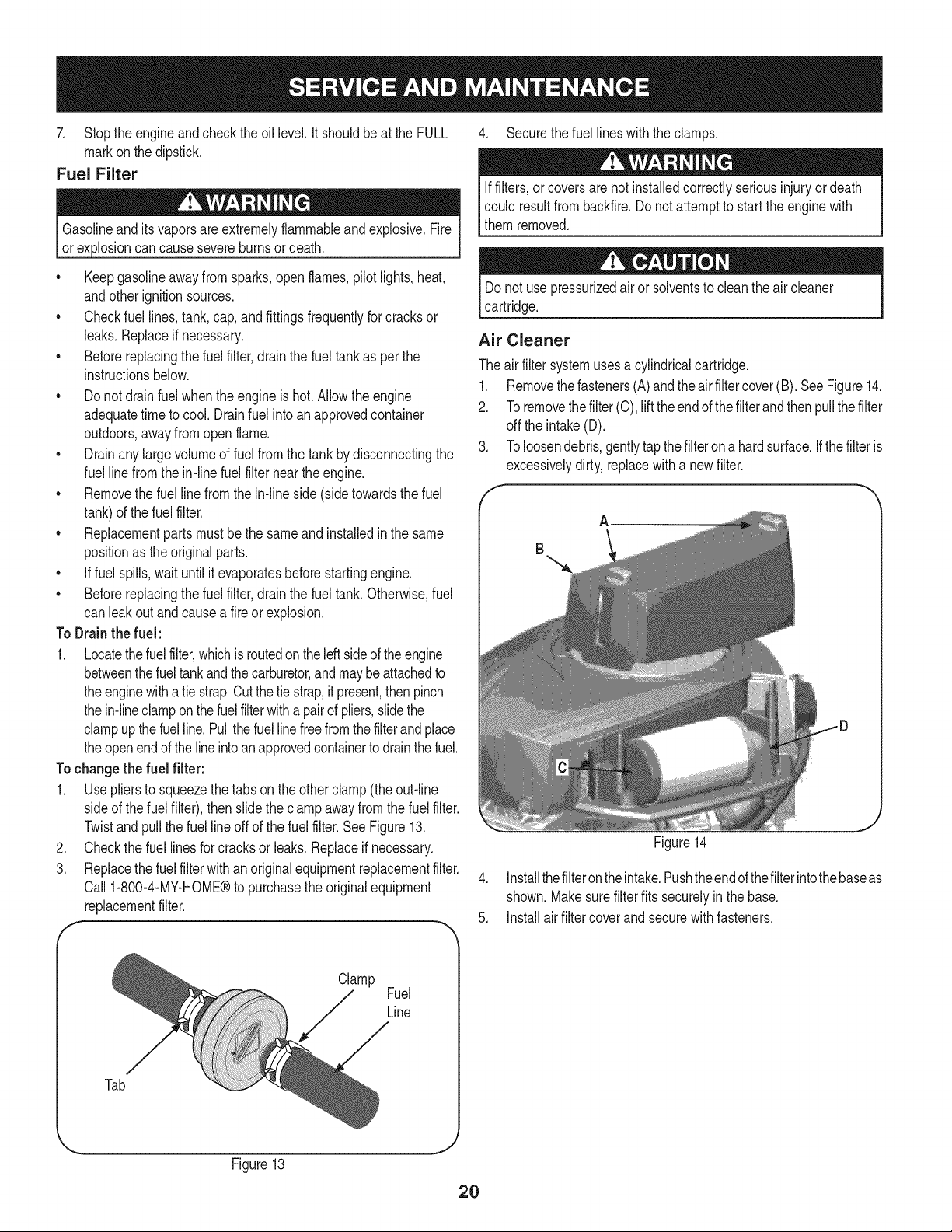
Tochangethe fuel filter:
1. Usepliersto squeezethe tabsonthe otherclamp(theout-line
sideof the fuel filter),thenslidethe clamp awayfromthe fuel filter.
Twistandpull the fuellineoff of the fuelfilter.SeeFigure13.
2. Checkthe fuel linesfor cracksor leaks.Replaceif necessary.
3. Replacethe fuelfilterwithan originalequipmentreplacementfilter.
Call 1-800-4-MY-HOME®to purchasethe originalequipment
replacementfilter.
f
Donot use pressurizedair or solventsto cleanthe air cleaner
cartridge.
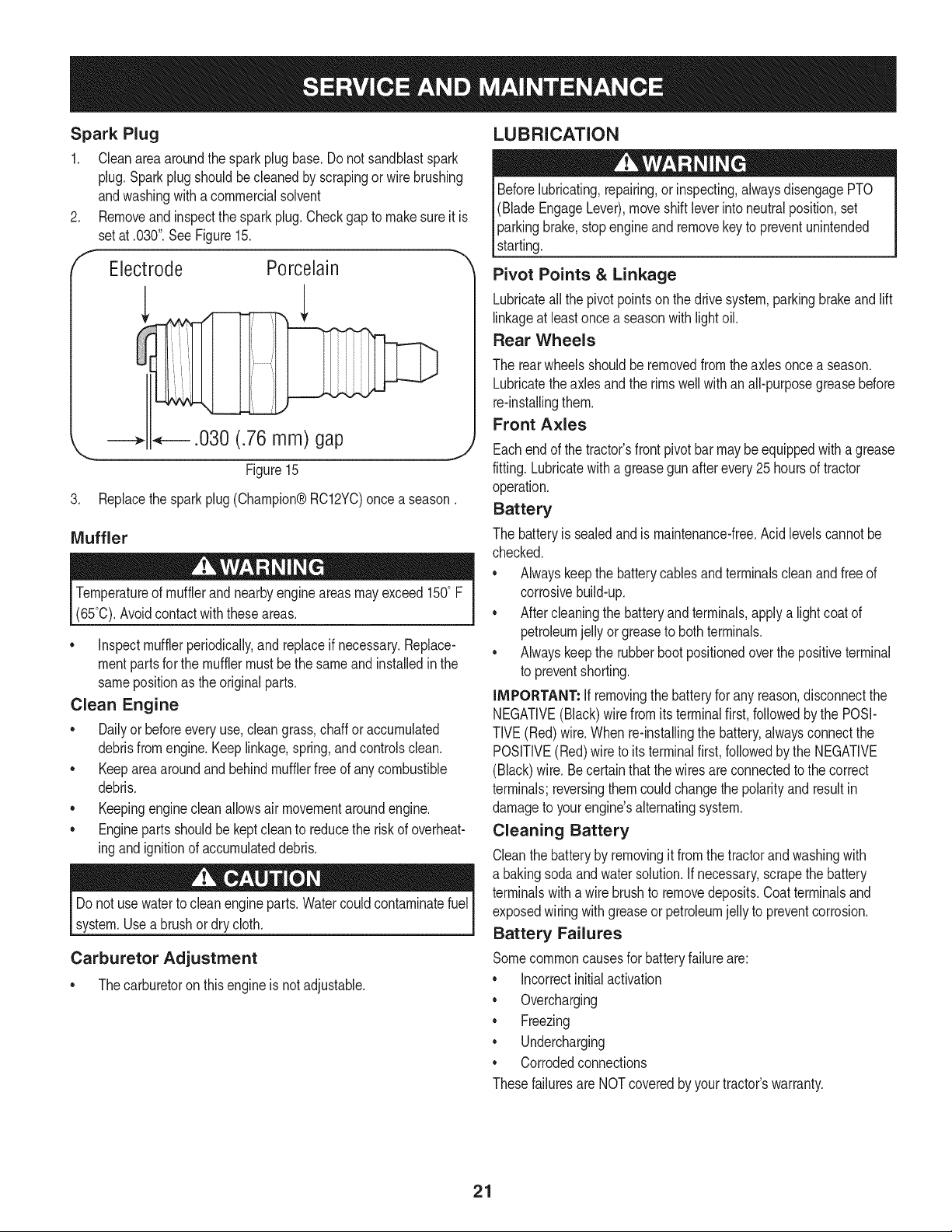
Air Cleaner
The air filtersystemusesa cylindricalcartridge.
1. Removethefasteners(A)andtheair filter cover(B). SeeFigure14.
2. Toremovethefilter (C), lifttheend ofthe filterandthen pullthefilter
off the intake(D).
3. Toloosendebris,gentlytapthefilter onahard surface,ifthe filteris
excessivelydirty,replacewitha newfilter.
A
B
Figure14
4. Installthefilterontheintake.Pushtheendofthefilterintothebaseas
shown.Makesurefilterfits securelyin thebase.
5. installair filtercoverand securewithfasteners.
Clamp
Fuel
Line
Tab
... J
Figure13
2O
Spark Plug
1. Cleanareaaroundthe spark plugbase.Do notsandblastspark
plug,Sparkplugshouldbe cleanedby scrapingorwire brushing
andwashingwith a commercialsolvent
Removeand inspectthe sparkplug.Checkgap to makesureit is
setat .030".See Figure15.
Electrode Porcelain
_.030 (.76 mm) gap
\
Figure15
3. Replacethesparkplug(Champion®RC12YC)once a season.
Muffler
Temperatureof mufflerandnearbyengineareasmayexceed150° F
(65°0).Avoidcontactwiththese areas.
• inspectmufflerperiodically,and replaceif necessary.Replace-
mentpartsfor the mufflermustbe the sameand installedin the
samepositionas the originalparts.
Clean Engine
• Dailyor beforeeveryuse, cleangrass,chaff oraccumulated
debrisfromengine.Keeplinkage,spring,andcontrolsclean.
• Keeparea aroundandbehindmufflerfreeof any combustible
debris.
• Keepingenginecleanallowsair movementaroundengine.
• Engineparts shouldbe keptcleanto reducethe risk of overheat-
ingandignitionof accumulateddebris.
Do notuse waterto cleanengineparts.Watercouldcontaminatefuel
system.Use a brushordry cloth.
Carburetor Adjustment
• Thecarburetoron this engineisnot adjustable.
LUBRICATION
Beforelubricating,repairing,or inspecting,alwaysdisengagePTO
(BladeEngageLever),moveshift leverinto neutralposition,set
parkingbrake,stopengineand removekeyto preventunintended
starting.
Pivot Points & Linkage
Lubricateall the pivot pointsonthe drivesystem,parkingbrakeand lift
linkageat leastonce a seasonwithlightoil.
Rear Wheels
The rear wheelsshouldberemovedfrom theaxlesoncea season.
Lubricatetheaxles andthe rimswellwithan all-purposegreasebefore
re-installingthem.
Front Axles
Eachend of thetractor'sfrontpivotbar maybe equippedwitha grease
fitting.Lubricatewith a greasegun afterevery25 hoursof tractor
operation.
Battery
The batteryis sealedand is maintenance-free.Acidlevelscannot be
checked.
• Alwayskeepthe batterycablesand terminalscleanand free of
corrosivebuild-up.
• After cleaningthe batteryandterminals,applya lightcoatof
petroleumjelly orgreaseto bothterminals.
• Alwayskeepthe rubberbootpositionedoverthe positiveterminal
to preventshorting.
IMPORTANT: If removingthe batteryfor any reason,disconnectthe
NEGATIVE(Black)wirefrom itsterminalfirst,followedby the POSI-
TIVE(Red)wire.When re-installingthe battery,alwaysconnectthe
POSITIVE(Red)wire to its terminalfirst,followedbythe NEGATIVE
(Black)wire.Becertainthat the wiresareconnectedto the correct
terminals;reversingthemcouldchangethe polarityandresult in
damageto yourengine'salternatingsystem.
Cleaning Battery
Cleanthe batteryby removingit fromthe tractorand washingwith
a bakingsodaandwatersolution.If necessary,scrapethe battery
terminalswith a wirebrushto removedeposits.Coatterminalsand
exposedwiringwithgreaseor petroleumjelly to preventcorrosion.
Battery Failures
Somecommoncausesfor batteryfailureare:
• incorrectinitialactivation
• Overcharging
• Freezing
• Undercharging
• Corrodedconnections
Thesefailuresare NOTcoveredbyyourtractor'swarranty.
21
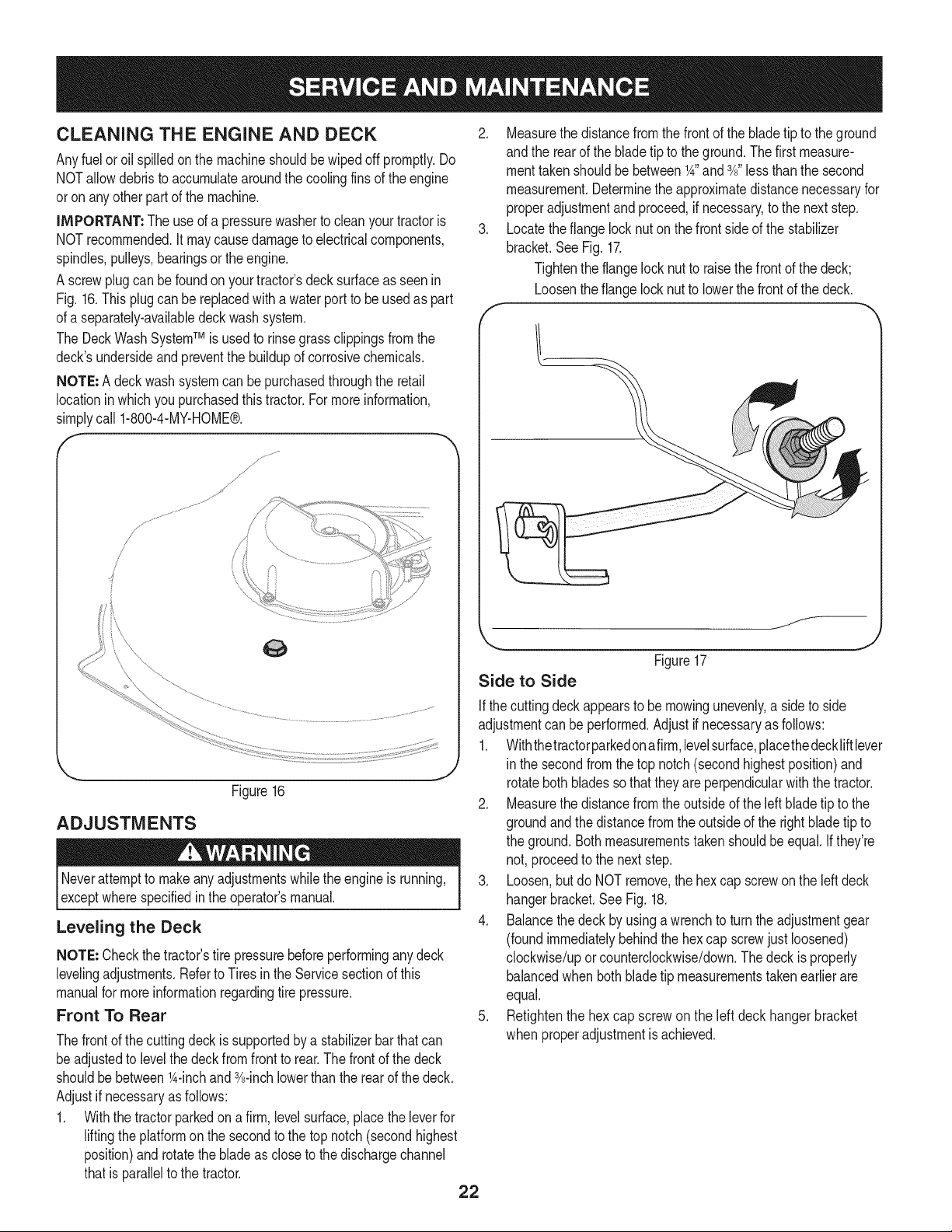
CLEANING THE ENGINE AND DECK
Anyfuel or oil spilledonthe machineshouldbewipedoff promptly.Do
NOTallowdebristo accumulatearoundthe coolingfins of the engine
oron anyother partof the machine.
IMPORTANT: The useof a pressurewasherto cleanyourtractoris
NOTrecommended.It maycausedamageto electricalcomponents,
spindles,pulleys,bearingsorthe engine.
A screwplug can be foundon yourtractor'sdeck surfaceas seenin
Fig. 16.This plugcan bereplacedwitha waterport to be usedas part
of a separately-availabledeckwashsystem.
The DeckWashSystemTM is usedto rinsegrassclippingsfromthe
deck'sundersideandpreventthe buildupof corrosivechemicals.
NOTE: A deckwashsystemcan be purchasedthroughthe retail
locationinwhich youpurchasedthistractor.For moreinformation,
simplycall 1-800-4-MY-HOME®.
/
/
Figure16
ADJUSTMENTS
Neverattemptto makeanyadjustmentswhilethe engineis running,
exceptwherespecifiedin the operator'smanual.
Leveling the Deck
NOTE: Checkthe tractor'stire pressurebeforeperforminganydeck
levelingadjustments.Referto Tires inthe Servicesectionof this
manualfor moreinformationregardingtire pressure.
Front To Rear
2. Measurethedistancefromthe front of the bladetip to the ground
andthe rearof the bladetip to theground.Thefirst measure-
menttakenshouldbe between1A"and3A"lessthanthe second
measurement.Determinethe approximatedistancenecessaryfor
properadjustmentand proceed,if necessary,to the nextstep.
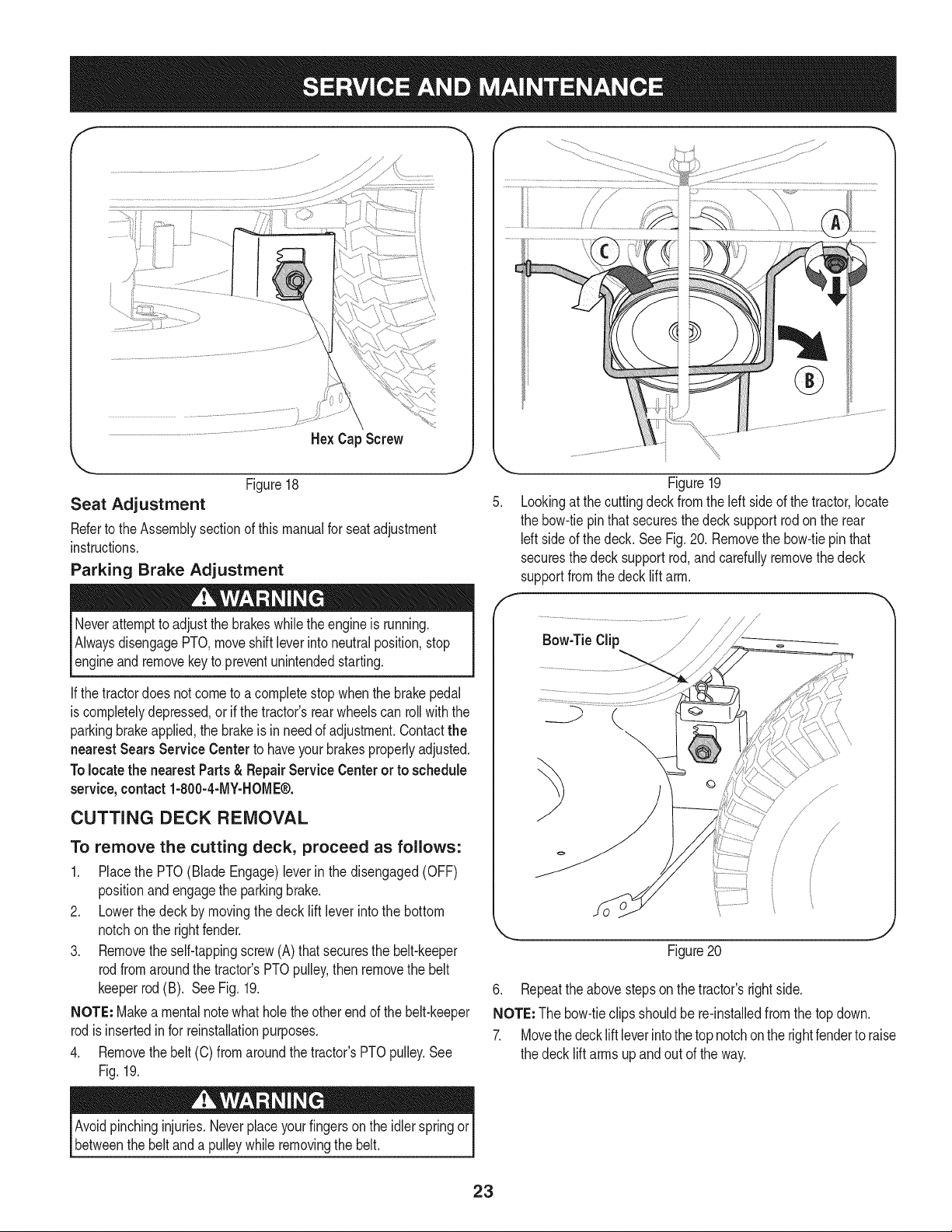
3. Locatethe flangelock nut on the front sideof the stabilizer
bracket.SeeFig. 17.
Tightenthe flangelocknut to raisethe frontof the deck;
Loosentheflange locknutto lowerthefrontof thedeck.
Thefrontof the cuttingdeck is supportedby a stabilizerbarthatcan
beadjustedto levelthe deckfrom frontto rear.Thefrontof the deck
shouldbebetween1A-inchand 3A-inchlowerthan the rearof thedeck.
Adjustif necessaryas follows:
1. Withthe tractorparkedon a firm,levelsurface,placethe leverfor
liftingthe platformon the secondto the top notch(secondhighest
position)androtatethe bladeas close to the dischargechannel
thatis parallelto the tractor.
22
f
/
=
Figure17
Side to Side
Ifthe cuttingdeckappearsto be mowingunevenly,a sideto side
adjustmentcan beperformed.Adjustif necessaryas follows:
1. Withthetractorparkedonafirm,levelsurface,placethedeckliftlever
in the secondfromthetop notch(secondhighestposition)and
rotatebothbladessothatthey are perpendicularwiththe tractor.
2. Measurethedistancefromthe outsideof the left bladetip to the
groundandthe distancefrom the outsideof the rightbladetip to
the ground.Bothmeasurementstakenshouldbeequal.If they're
not, proceedto the nextstep.
3. Loosen,but do NOTremove,the hexcap screwon the leftdeck
hangerbracket.See Fig. 18.
4. Balancethedeckby usinga wrenchto turn theadjustmentgear
(foundimmediatelybehindthehex cap screwjust loosened)
clockwise/uporcounterclockwise/down.Thedeckis properly
balancedwhen bothbladetip measurementstakenearlier are
equal.
5. Retightenthe hex cap screwon the left deck hangerbracket
when properadjustmentis achieved.
He× Cap Screw
'_. ._
Figure18
Seat Adjustment
Referto the Assemblysectionof this manualfor seatadjustment
instructions.
Parking Brake Adjustment
Neverattemptto adjustthe brakeswhiletheengine is running.
AlwaysdisengagePTO,moveshift leverintoneutralposition,stop
engineandremovekeyto preventunintendedstarting.
If thetractordoes notcometo acompletestopwhenthe brakepedal
is completelydepressed,or if the tractor'srearwheelscan roll withthe
parkingbrakeapplied,the brakeis in needof adjustment.Contactthe
nearest Sears Service Centerto haveyourbrakesproperlyadjusted.
Tolocatethe nearest Parts& Repair ServiceCenteror to schedule
service,contact 1-800-4-MY-HOME®.
CUTTING DECK REMOVAL
To remove the cutting deck, proceed as follows:
1. Placethe PTO(Blade Engage)leverin the disengaged(OFF)
positionand engagethe parkingbrake.
2. Lowerthe deck by movingthe deck lift lever intothe bottom
notchon the rightfender.
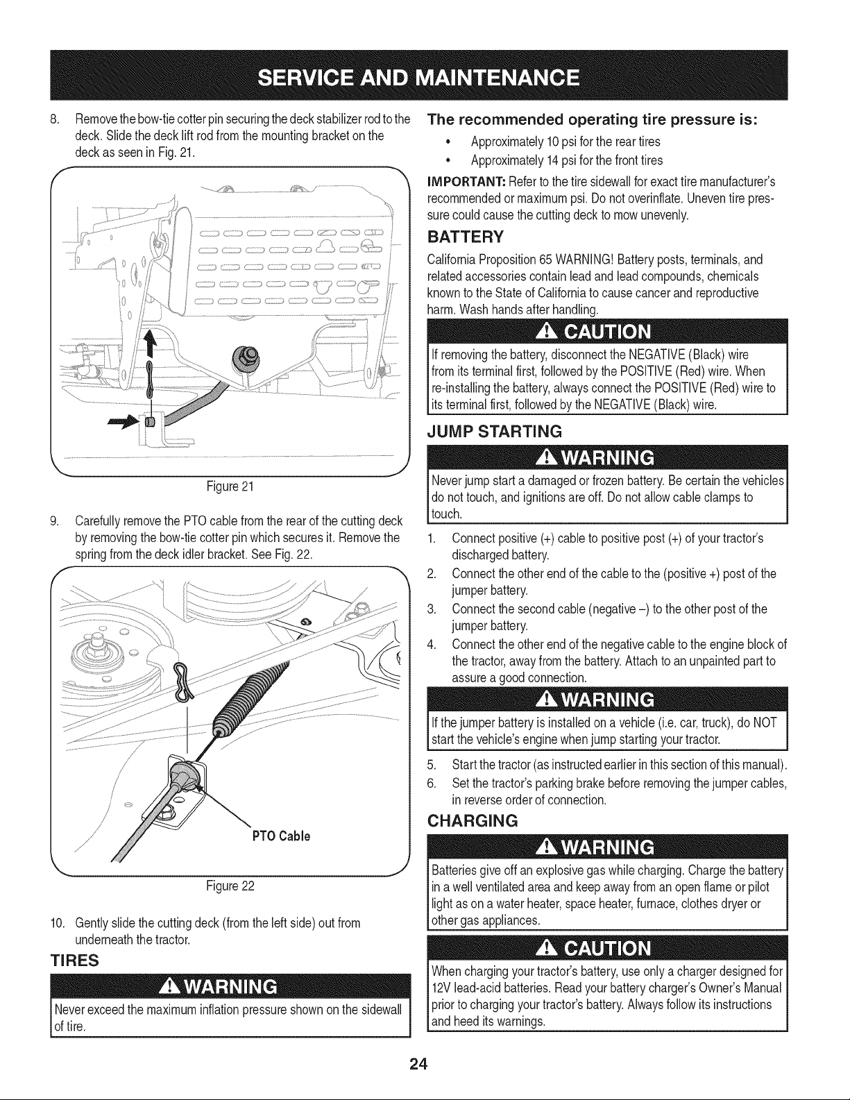
3. Removetheself-tappingscrew(A) that securesthe belt-keeper
rodfromaroundthe tractor'sPTOpulley,thenremovethe belt
keeperrod(B). See Fig. 19.
NOTE: Makea mentalnotewhatholethe otherendof the belt-keeper
rodisinsertedinfor reinstallationpurposes.
4. Removethebelt (C) from aroundthetractor'sPTOpulley.See
Fig.19.
F
Figure19
Lookingat thecuttingdeck fromthe leftside of the tractor,locate
the bow-tiepinthat securesthedecksupportrod onthe rear
Idt sideof the deck. SeeFig.20. Removethe bow-tiepinthat
securesthedeck supportrod,and carefullyremovethe deck
supportfromthe decklift arm.
Bow-TieClip
6. Repeatthe abovestepson the tractor'srightside.
NOTE: The bow-tieclips shouldbe re-installedfromthe top down.
7. Movethedeck liftleverintothe topnotchon the rightfenderto raise
the decklift armsup and out of theway.
Avoidpinchinginjuries.Neverplaceyourfingerson the idler springor
betweenthe belt anda pulleywhile removingthe belt.
23
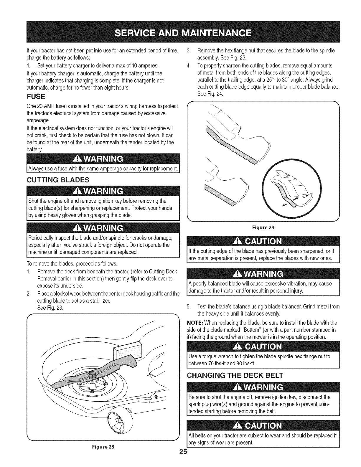
8. Removethebow-tiecotterpinsecuringthedeck stabilizerrodto the
deck.Slidethedeck lift rodfrom the mountingbracketon the
deckasseen in Fig.21.
............./1;_,_......................... / ..............................
_,., j2
Figure21
.
f
Carefullyremovethe PTOcablefrom the rearof the cuttingdeck
by removingthe bow-tiecotterpinwhichsecuresit. Removethe
springfromthe deckidlerbracket.See Fig.22.
PTOCable
_ J
Figure22
10. Gentlyslidethe cuttingdeck(fromthe left side)out from
underneaththe tractor.
TIRES
Neverexceedthe maximuminflationpressureshownon the sidewall
of tire.
The recommended operating tire pressure is:
• Approximately10psi for the reartires
• Approximately14psi for the fronttires
IMPORTANT=Referto the tire sidewallfor exacttire manufacturer's
recommendedor maximumpsi.Donot ovednflate.Uneventire pres-
surecould causethe cuttingdeckto mowunevenly.
BATTERY
CaliforniaProposition65 WARNING!Batteryposts,terminals,and
relatedaccessoriescontainlead andleadcompounds,chemicals
knownto the State of Californiato causecancer andreproductive
harm.Washhandsafter handling.
If removingthe battery,disconnectthe NEGATIVE(Black)wire
fromits terminalfirst, followedbythe POSITIVE(Red) wire.When
relinstallingthe battery,alwaysconnectthe POSITIVE(Red)wire to
Its termna f rst,fo owedby the NEGATVE (Back) w re.
JUMP STARTING
Neverjump starta damagedor frozenbattery.Becertain thevehicles
do not touch,and ignitionsareoff. Do notallowcable clampsto
touch.
1. Connectpositive(+)cableto positivepost(+)of yourtractor's
dischargedbattery.
2. Connecttheotherendof thecableto the (positive+) postof the
jumperbattery.
3. Connectthesecondcable (negative-) to theother postof the
jumperbattery.
4. Connecttheotherendof thenegativecableto the engineblockof
the tractor,awayfromthe battery.Attachto anunpaintedpartto
assurea goodconnection.
Ifthejumper batteryis installedona vehicle (i.e.car,truck),do NOT
startthe vehicle'senginewhenjump startingyourtractor.
5. Startthetractor(asinstructedearlierinthissectionofthismanual).
6. Set the tractor'sparkingbrakebeforeremovingthejumpercables,
in reverseorderof connection.
CHARGING
give offan explosivegas whilecharging.Chargethe batteryI
Batteries
ina wellventilatedareaandkeepawayfroman openflame or pilot
ght as on a waterheater,spaceheater,furnace,c othes dryeror |
othergas appliances.
J
Whenchargingyourtractor'sbattery,useonlya chargerdesignedfor I
12Vlead-acidbatteries.Readyourbatterychargers Owners Manual
priorto chargingyourtractors battery.Alwaysfollowits instructions I
land heed ts warnngs. j
24
If yourtractorhasnot beenputinto usefor an extendedperiodof time,
chargethe batteryas follows:
1. Setyour batterychargerto delivera maxof 10amperes.
If yourbatterychargeris automatic,chargethe batteryuntilthe
chargerindicatesthatchargingis complete.If the chargeris not
automatic,chargefor no fewerthaneight hours.
FUSE
One20 AMPfuse is installedin yourtractor'swiringharnessto protect
the tractor'selectricalsystemfromdamagecausedbyexcessive
amperage.
If theelectricalsystemdoesnot function,or yourtractor'senginewill
not crank,first checkto be certainthat the fuse hasnot blown.It can
befoundat the rear of the unit,underneaththefenderlocatedby the
battery.
Alwaysusea fuse withthe sameamperagecapacityfor replacement.
CUTTING BLADES
Shutthe engineoff andremoveignitionkey beforeremovingthe
cuttingblade(s)for sharpeningor replacement.Protectyourhands
by usingheavygloveswhengraspingthe blade.
Periodicallyinspectthe bladeand/or spindlefor cracks ordamage,
especiallyafter you'vestrucka foreignobject. Donot operatethe
machineuntil damagedcomponentsare replaced.
Toremovethe blades,proceedas follows.
1. Removethedeck from beneaththe tractor,(referto CuttingDeck
Removalearlierinthis section)thengentlyflip thedeckoverto
exposeitsunderside.
2. Placeablockofwoodbetweenthecenterdeckhousingbaffleandthe
cuttingbladeto act as a stabilizer.
SeeFig. 23.
f
.
4.
Removethe hexflangenut thatsecuresthe bladeto the spindle
assembly.See Fig.23.
To properlysharpenthe cuttingblades,removeequalamounts
of metalfrombothendsof the bladesalongthe cuttingedges,
parallelto the trailingedge,at a 250.to 300angle.Alwaysgrind
eachcutting bladeedgeequallyto maintainproperblade balance.
SeeFig.24.
Figure 24
Ifthe cuttingedgeof the bladehas previouslybeensharpened,or if
any metalseparationis present,replacethe bladeswith newones.
A poorlybalancedbladewill causeexcessivevibration,maycause
damageto the tractorand/or resultin personalinjury.
5. Testthe blade'sbalanceusinga bladebalancer.Grindmetalfrom
the heavysideuntil it balancesevenly.
NOTE: Whenreplacingthe blade,be sureto installthe blade withthe
sideof the blademarked"Bottom" (or witha part numberstampedin
it)facingthe groundwhenthe moweris in the operatingposition.
Usea torquewrenchto tightenthe bladespindlehexflangenut to
between70Ibs-ftand 90 Ibs-ft.
CHANGING THE DECK BELT
Besureto shutthe engineoff, removeignitionkey,disconnectthe
Isparkplugwire(s)and groundagainstthe engineto preventunin-
ltended startingbeforeremovingthe belt.
All beltsonyourtractorare subjectto wearand shouldbereplacedif
any signsof wearare present.
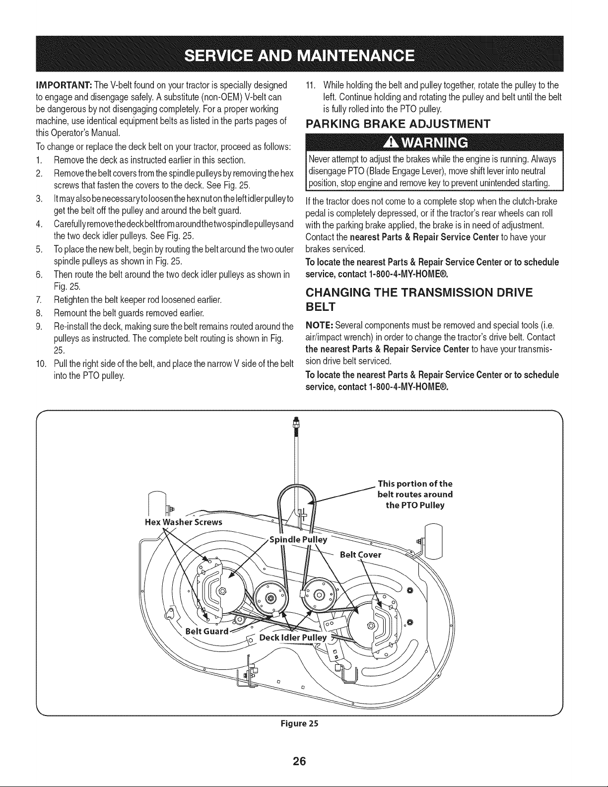
iMPORTANT: The V-beltfoundon yourtractoris speciallydesigned
to engageanddisengagesafely.A substitute(non-OEM)V-beltcan
bedangerousby notdisengagingcompletely.Fora properworking
machine,useidenticalequipmentbeltsas listedin the parts pagesof
thisOperator'sManual.
Tochangeor replacethe deckbelt onyourtractor,proceedas follows:
1. Removethe deck as instructedearlier inthis section.
2. Removethebeltcoversfromthe spindlepulleysbyremovingthehex
screwsthatfastenthe coversto thedeck. See Fig.25.
3. Itmayalsobenecessarytoloosenthehexnutontheleftidlerpulleyto
getthe beltoffthe pulleyandaroundthe beltguard.
4. Carefullyremovethedeckbeltfromaroundthetwospindlepulleysand
thetwo deckidlerpulleys,SeeFig, 25,
5. Toplacethenewbelt, beginbyroutingthebeltaroundthetwoouter
spindlepulleysas showninFig. 25.
6. Thenroutethe beltaroundthe twodeck idlerpulleysas shownin
Fig.25.
7. Retightenthe belt keeperrodloosenedearlier.
8. Remountthebelt guardsremovedearlier,
9. Re-installthedeck, makingsurethebeltremainsroutedaroundthe
pulleysas instructed.The completebelt routingisshownin Fig.
25,
10. Pullthe rightsideofthe belt,and placethe narrowV sideof thebelt
intothe PTOpulley.
11. Whileholdingthe belt andpulleytogether,rotatethe pulleyto the
left. Continueholdingand rotatingthe pulleyand belt untilthe belt
is fullyrolledinto the PTOpulley.
PARKING BRAKE ADJUSTMENT
Neverattemptto adjustthe brakeswhiletheengineis running.Always
disengagePTO(BladeEngageLever),moveshiftleverintoneutral
position,stopengineand removekeyto preventunintendedstarting.
Ifthe tractordoesnot cometo a completestop whenthe clutch-brake
pedalis completelydepressed,or if the tractor'srearwheelscan roll
withthe parkingbrakeapplied,the brakeis inneedof adjustment.
Contactthe nearest Parts & Repair Service Center to haveyour
brakesserviced.
Tolocatethe nearestParts& RepairServiceCenter or to schedule
service,contact1-800-4-MY-HOME®.
CHANGING THE TRANSMiSSiON DRIVE
BELT
NOTE: Severalcomponentsmust beremovedandspecialtools(i.e.
air/impactwrench)inorder to changethetractor'sdrivebelt.Contact
the nearest Parts & Repair Service Centerto haveyourtransmis-
sion drivebelt serviced.
Tolocatethe nearestParts& RepairServiceCenter or to schedule
service, contact 1-800-4-MY-HOME®.
Hex Washer Screws
This portion of the
belt routes around
the PTO Pulley
Belt Cover
Belt Guard
_ _oo Deckidier Pu,,ey
Figure 25
26
Neverstorelawntractorwithfuel intankindoorsor in poorly
ventilatedareaswherefuel fumesmayreachan openflame,spark,
orpilot lightas ona furnace,water heater,clothesdryer,or gas
appliance.
PREPARING THE ENGINE
IMPORTANT:Fuelleft in thefuel tank duringwarmweatherdeterio-
ratesandwill causeseriousstartingproblems.
To preventgumdepositsfromforminginsidethe engine'scarburetor
andcausingpossiblemalfunctionof theengine,thefuel systemmust
be eithercompletelyemptied,orthe gasolinemustbe treatedwitha
stabilizerto preventdeterioration.
1. Ifusingafuel stabilizer:
a. Readthe productmanufacturer'sinstructionsandrecom-
mendations.
b. Addto clean,freshgasolinethe correctamountof stabilizer
for the capacityof the fuel system.
c. Fillthe fueltank withtreatedfuel andrun the enginefor 2-3
minutesto get stabilizedfuel intothe carburetor.
2. Ifemptyingthe fuel system:
a. Donot drainfuel whenthe engineis hot. Allowthe engine
adequatetime to cool.Drainfuelinto anapprovedcontainer
outdoors,awayfrom openflame.
b. Drainany largevolumeof fuel from thetank bydisconnect-
ing thefuel linefrom the in-linefuel filternearthe engine.
Seethe completeinstructionsfor DrainingThe Fuellaterin
this section.
Gasolineis extremelyflammableand can be explosiveundercertain
conditions.Draingasolinebeforestoringthe equipmentfor extended
periods.Drainfuel only intoanapprovedcontaineroutdoors,away
froman openflame.Allowengineto cool.Extinguishcigarettes,
cigars,pipes,and othersourcesof ignitionpriorto drainingfuel.
Storegasolinein an approvedcontainerinsafelocation.
c. Reconnectthe fuel lineandrunthe engineuntil it starts to
falter,thenuse thechoketo keeptheenginerunninguntilall
fuel in thecarburetorhas beenexhausted.
d. Disconnectthefuel lineanddrain any remaininggasoline
fromthe system.
DRAiNiNG THE FUEL
1. Locatethe fuel filter,whichis locatedonthe left sideof the
engine,andmaybe attachedto the enginewitha tie strap.
2. Cutthe tie strap,if present,then pinchthe in-lineclamponthe
fuel filter witha pair of pliers,slidethe clampupthe fuel line.
3. Pullthe fuel line freefromthe filterandplacethe open endof the
lineintoan approvedcontainerto drain the fuel.
PREPARING THE LAWN TRACTOR
1. Cleanand lubricatetractorthoroughlyas describedin the lubrica-
tion instructions.
2. Donot usea pressurewasheror gardenhoseto cleanyour unit.
3. Storemowerin a dry,cleanarea. Do notstorenextto corrosive
materials,suchas fertilizer.
Gasolineis a toxicsubstance.Disposeof gasolineproperly.Contact
your localauthoritiesfor approveddisposalmethods.
3. Removethe sparkplug andpour one(1)ounceof engineoil
throughthe sparkplugholeintothe cylinder.Cranktheengine
severaltimesto distributethe oil. Replacethe spark plug.
27
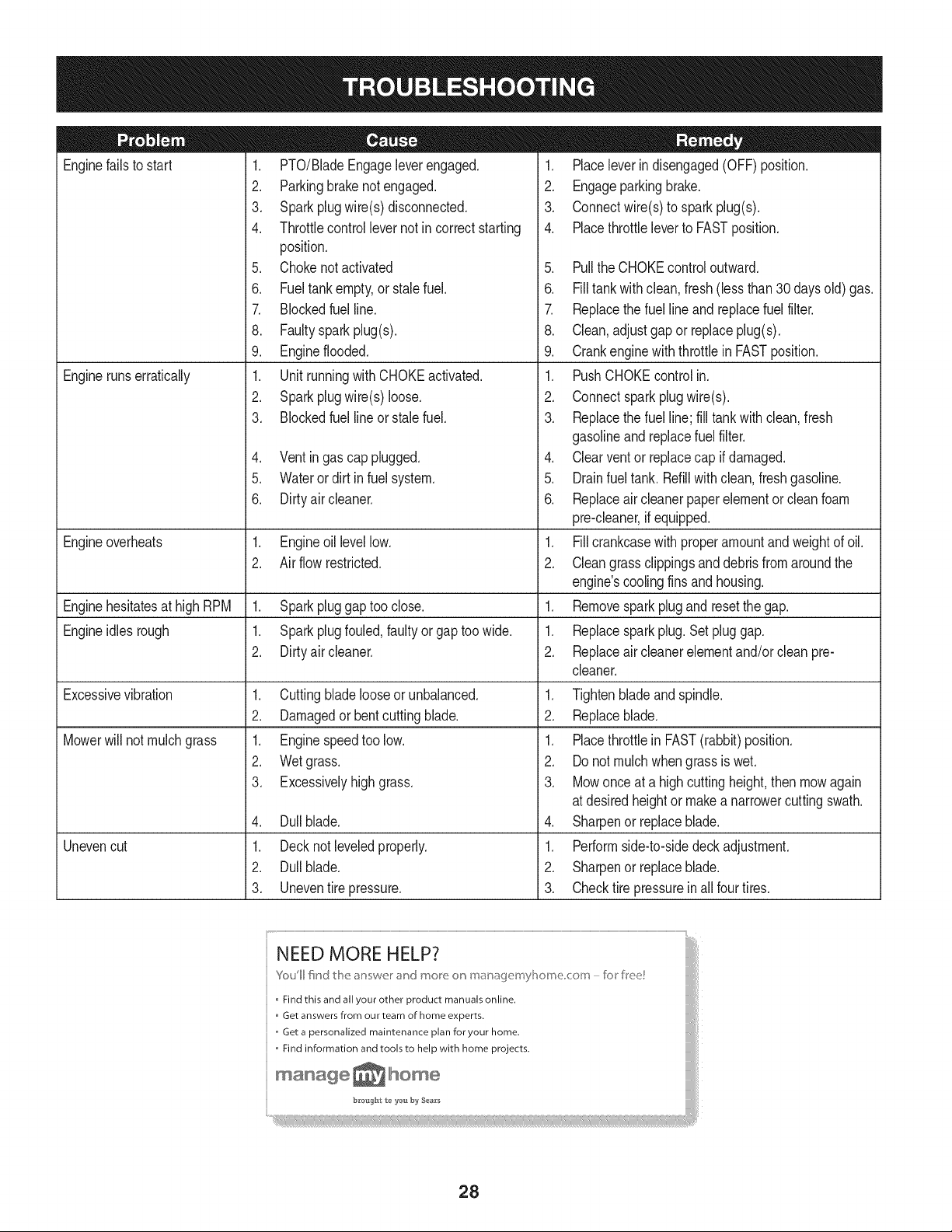
Enginefails to start
Enginerunserratically
1. PTO/BladeEngageleverengaged.
2. Parkingbrakenotengaged.
3. Sparkplugwire(s)disconnected.
4. Throttlecontrollevernot in correctstarting
position.
5. Chokenotactivated
6. Fueltankempty,or stalefuel.
7. Blockedfuel line.
8. Faultyspark plug(s).
9. Engineflooded.
1. UnitrunningwithCHOKEactivated.
2. Sparkplugwire(s)loose.
3. Blockedfuel lineor stalefuel.
4. Ventingas cap plugged.
5. Waterordirt in fuel system.
6. Dirtyair cleaner.
Engineoverheats 1. Engineoillevellow. 1.
2. Airflowrestricted. 2.
Enginehesitatesat highRPM 1. Sparkpluggaptoo close. 1.
Engineidles rough 1. Sparkplugfouled,faultyor gaptoo wide. 1.
2. Dirtyair cleaner. 2.
Excessivevibration
Mowerwill not mulchgrass
Unevencut
1. Cuttingbladelooseor unbalanced.
2. Damagedor bentcuttingblade.
1. Enginespeedtoo low.
2. Wetgrass.
3. Excessivelyhighgrass.
4. Dullblade.
1. Decknot leveledproperly.
2. Dullblade.
3. Uneventire pressure.
1. Placeleverindisengaged(OFF)position.
2. Engageparkingbrake.
3. Connectwire(s)to sparkplug(s).
4. Placethrottleleverto FASTposition.
5. PulltheCHOKEcontroloutward.
6. Filltankwithclean, fresh(lessthan30 daysold) gas.
7. Replacethe fuel line andreplacefuel filter.
8. Clean,adjustgapor replaceplug(s).
9. Crankenginewiththrottlein FASTposition.
1. PushCHOKEcontrol in.
2. Connectspark plugwire(s).
3. Replacethe fuel line;fill tankwithclean,fresh
gasolineand replacefuel filter.
4. Clearventor replacecap if damaged.
5. Drainfueltank. Refillwith clean,freshgasoline.
6. Replaceair cleanerpaperelementor cleanfoam
pre-cleaner,if equipped.
Fillcrankcasewith properamountandweightof oil.
Cleangrass clippingsanddebrisfromaroundthe
engine'scoolingfinsand housing.
Removesparkplug andresetthe gap.
Replacesparkplug.Set pluggap.
Replaceair cleanerelementand/orclean pre-
cleaner.
1. Tightenbladeandspindle.
2. Replaceblade.
1. Placethrottlein FAST(rabbit)position.
2. Do notmulch whengrass is wet.
3. Mowonce at a highcuttingheight,then mowagain
at desiredheightor makea narrowercuttingswath.
4. Sharpenor replaceblade.
1. Performside-to-sidedeckadjustment.
2. Sharpenor replaceblade.
3. Checktire pressureinall fourtires.
NEED MORE HELP?
Youll fkld t_e answe_ _"ct mo_e o_ maoagemyP_ome <:ore - fi:_r free!
Find this and all your other product manuals online.
Get answers from our team of home experts.
,, Get a personalized maintenance plan for your home.
,, Find information and tools to help with home projects.
maoage _ home
b_*oug_t t_ _'ou by Sea_'s
28
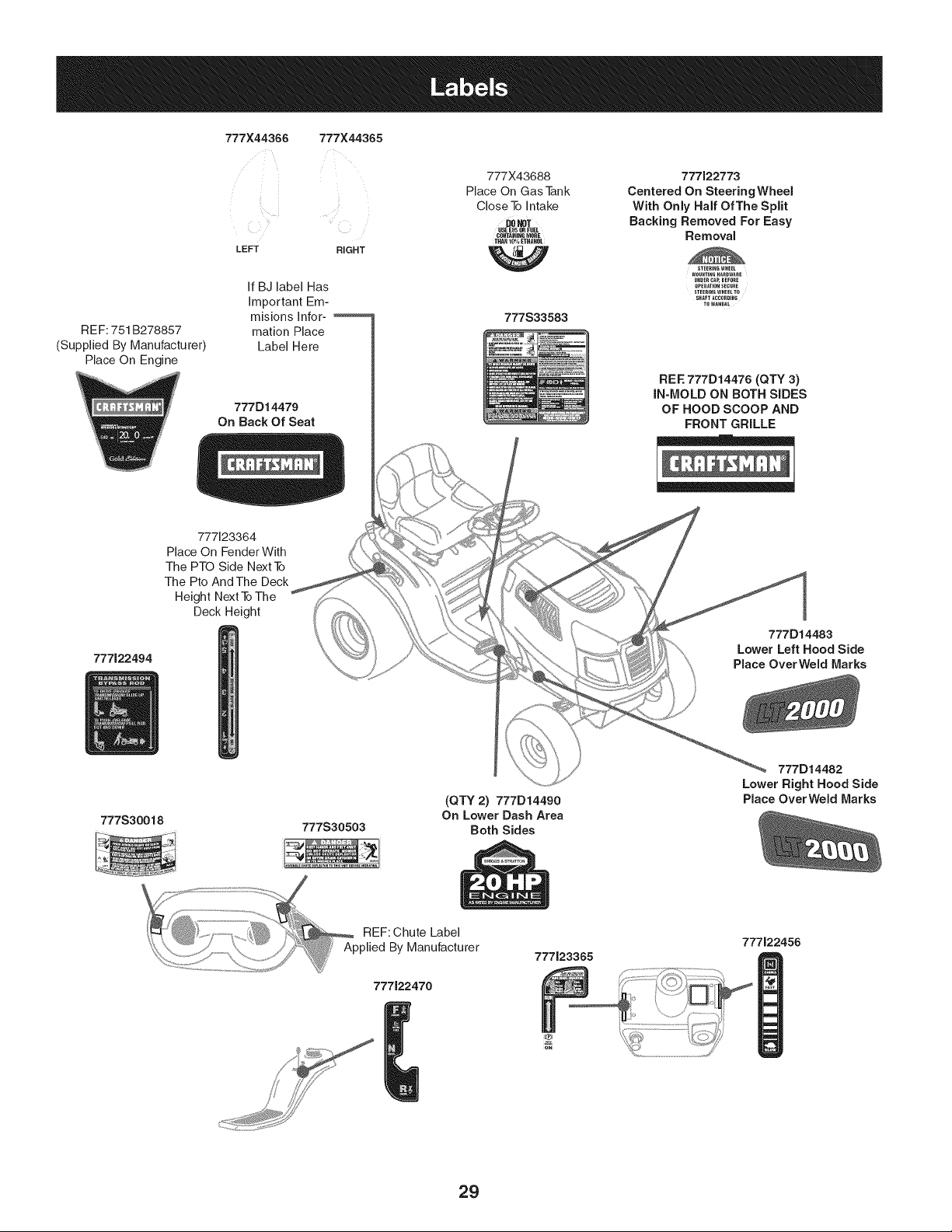
777X44366 777X44365
LEFT RIGHT
REF: 751 B278857
(Supplied By Manufacturer)
Place On Engine
If BJ label Has
important Em-
misions Infor ..........
marion Place
Label Here
777D14479
On Back Of Seat
777123364
Place On Fender With
The PTO Side Next To
The Pto And The Deck
Height Next ToThe
Deck Height
777122494
777X43688 777122773
Place On Gas Tank Centered On SteeringWheel
Close To intake With Only Half Of The Split
DONoT Sacking Removed For Easy
USEE_50_FU_
CO.TAm=,CMO.E Removal
THAN 10% ETHANOL
STEERING WHEEL
MOU"TINGHAROWARE
U"DERCAP,BEFORE
OPERATION SECURE
STEERING WHEEL TO
SHIFT ICCORDING
TO"ANUlL
777S33583
REE 777D14476 (QTY 3)
IN-MOLD ON SOTH SIDES
OF HOOD SCOOP AND
FRONT GRILLE
777D14483
Lower Left Hood Side
Place OverWeld Marks
777S30018
777S30503
(QTY 2) 777D14490
On Lower Dash Area
Both Sides
777D14482
Lower Right Hood Side
Place OverWeld Marks
777122470
777J23365
777122456
29
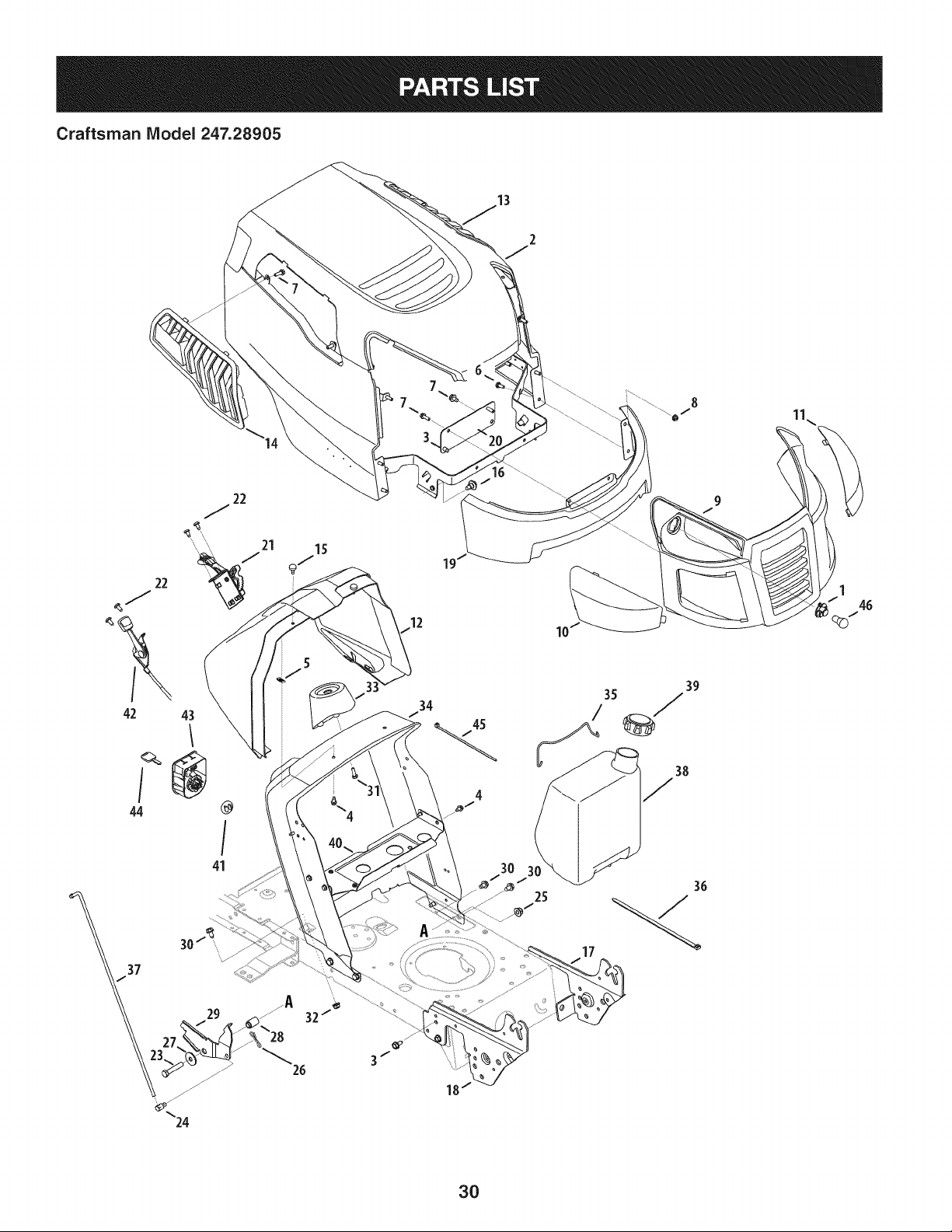
Craftsman IViodel 247.28905
11\
/
44
43
®
@
/
41
39
3O
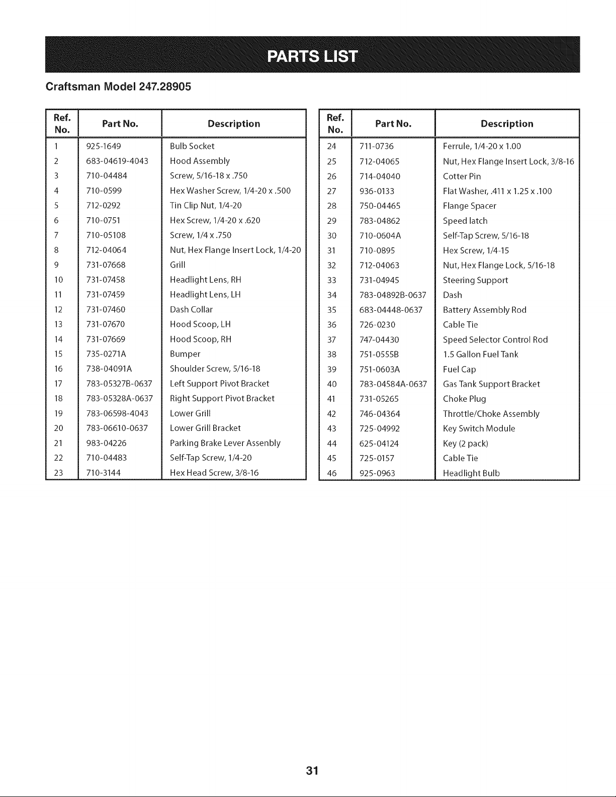
Craftsman Model 247.28905
Ref, I
No,
1 925-1649
2 683-04619-4043
3 710-04484
4 710-0599
5 712-0292
6 710-0751
7 710-05108
8 712-04064
9 731-07668
10 731-07458
II 731-07459
12 731-07460
13 731-07670
14 731-07669
15 735-0271A
16 738-04091A
17 783-05327B-0637
18 783-05328A-0637
19 783-06598-4043
20 783-06610-0637
21 983-04226
22 710-04483
23 710-3144
Part No, Description
Bulb Socket
Hood Assembly
Screw, 5/16-18 x .750
Hex Washer Screw, 1/4-20 x .500
Tin Clip Nut, 1/4-20
Hex Screw, 1/4-20 x .620
Screw, 1/4 x .750
Nut, Hex Flange Insert Lock, 1/4-20
Grill
Headlight Lens, RH
Headlight Lens, LH
Dash Collar
Hood Scoop, LH
Hood Scoop, RH
Bumper
Shoulder Screw, 5/16-18
Left Support Pivot Bracket
Right Support Pivot Bracket
Lower Grill
Lower Grill Bracket
Parking Brake Lever Assenbly
Self-Tap Screw, 1/4-20
Hex Head Screw, 3/8-16
Ref, I
No,
24 711-0736
25 712-04065
26 714-04040
27 936-0133
28 750-04465
29 783-04862
30 710-0604A
31 710-0895
32 712-04063
33 731-04945
34 783-04892B-0637
35 683-04448-0637
36 726-0230
37 747-04430
38 751-0555B
39 751-0603A
40 783-04584A-0637
41 731-05265
42 746-04364
43 725-04992
44 625-04124
45 725-0157
46 925-0963
Part No, Description
Ferrule, 1/4-20 x 1.00
Nut, Hex Flange Insert Lock, 3/8-16
Cotter Pin
Flat Washer, .411 x 1.25 x .100
Flange Spacer
Speed latch
Self-Tap Screw, 5/16-18
Hex Screw, 1/4-15
Nut, Hex Flange Lock, 5/16-18
Steering Support
Dash
Battery Assembly Rod
Cable Tie
Speed Selector Control Rod
1.5 Gallon Fuel Tank
Fuel Cap
Gas Tank Support Bracket
Choke Plug
Throttle/Choke Assembly
Key Switch Module
Key (2 pack)
Cable Tie
Headlight Bulb
31
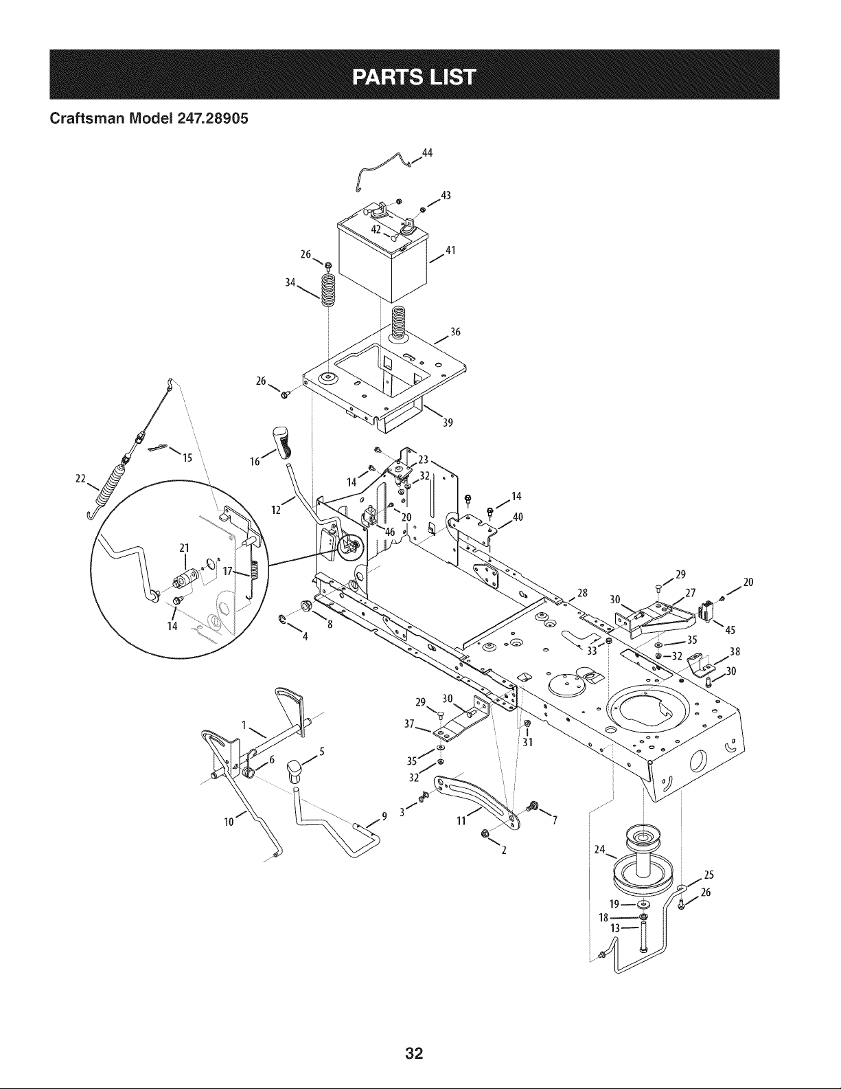
Craftsman IViodel 247.28905
36
22
21
14
12
39
28
3O
45
38
11
%
2
32
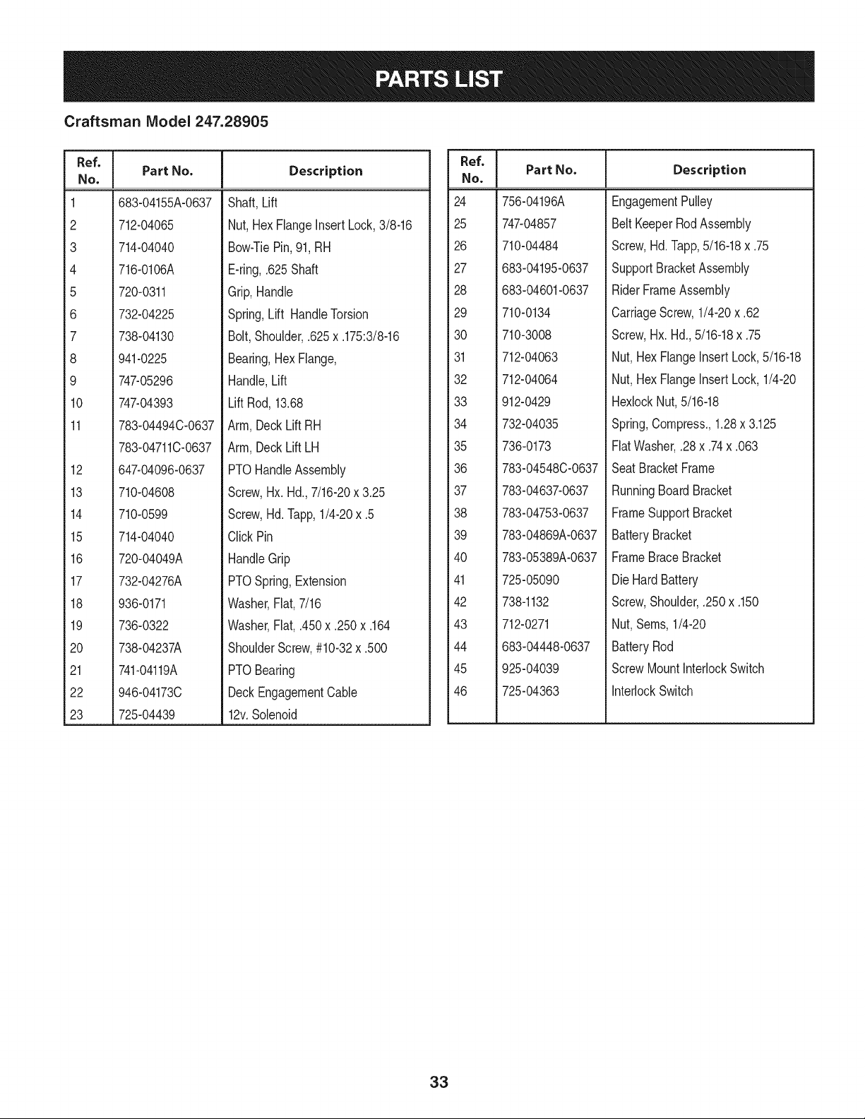
Craftsman Model 247.28905
Ref. I
No.
1 683-04155A-0637
2 712-04065
3 714-04040
4 716-0106A
5 720-0311
6 732-04225
7 738-04130
8 941-0225
9 747-05296
10 747-04393
11 783-04494C-0637
783-04711C-0637
12 647-04096-0637
13 710-04608
14 710-0599
15 714-04040
16 720-04049A
17 732-04276A
18 936-0171
19 736-0322
20 738-04237A
21 741-04119A
22 946-04173C
23 725-04439
Part No. Description
Shaft,Lift
Nut, HexFlangeinsertLock,3/8-16
Bow-TiePin,91,RH
E-ring,.625Shaft
Grip,Handle
Spring,Lift HandleTorsion
Bolt,Shoulder,.625x .175:3/8-16
Bearing,Hex Flange,
Handle,Lift
Lift Rod,13.68
Arm,DeckLift RH
Arm,DeckLift LH
PTOHandleAssembly
Screw,Hx. Hd.,7/16-20x 3.25
Screw,Hd. lapp, 1/4-20x .5
ClickPin
HandleGrip
PTOSpring,Extension
Washer,Fiat,7/16
Washer,Fiat, .450x .250x .164
ShoulderScrew,#10-32x .500
PTOBearing
DeckEngagementCable
12v.Solenoid
Ref. I
No.
24 756-04196A
25 747-04857
26 710-04484
27 683-04195-0637
28 683-04601-0637
29 710-0134
30 710-3008
31 712-04063
32 712-04064
33 912-0429
34 732-04035
35 736-0173
36 783-04548C-0637
37 783-04637-0637
38 783-04753-0637
39 783-04869A-0637
40 783-05389A-0637
41 725-05090
42 738-1132
43 712-0271
44 683-04448-0637
45 925-04039
46 725-04363
Part No. Description
EngagementPulley
BeltKeeperRodAssembly
Screw,Hd.lapp, 5/16-18x .75
SupportBracketAssembly
RiderFrameAssembly
CarriageScrew,1/4-20x .62
Screw,Hx.Hd.,5/16-18x .75
Nut,HexFlangeInsert Lock,5/16-18
Nut,HexFlangeInsert Lock,1/4-20
HexlockNut,5/16-18
Spring,Compress.,1.28x 3.125
FiatWasher,.28x .74x .063
Seat BracketFrame
RunningBoardBracket
FrameSupportBracket
BatteryBracket
FrameBraceBracket
DieHard Battery
Screw,Shoulder,.250x .150
Nut,Seres,1/4-20
BatteryRod
ScrewMountInterlockSwitch
InterlockSwitch
33
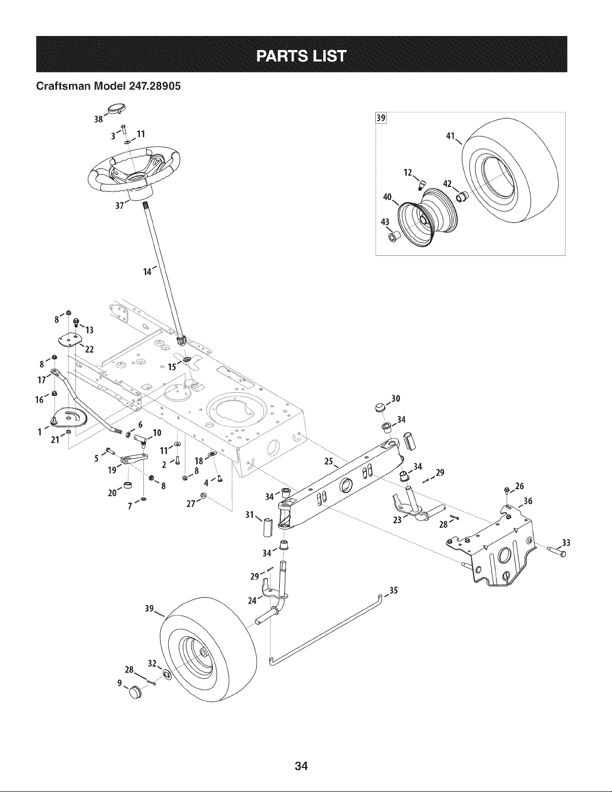
25
23
35
29
33
34
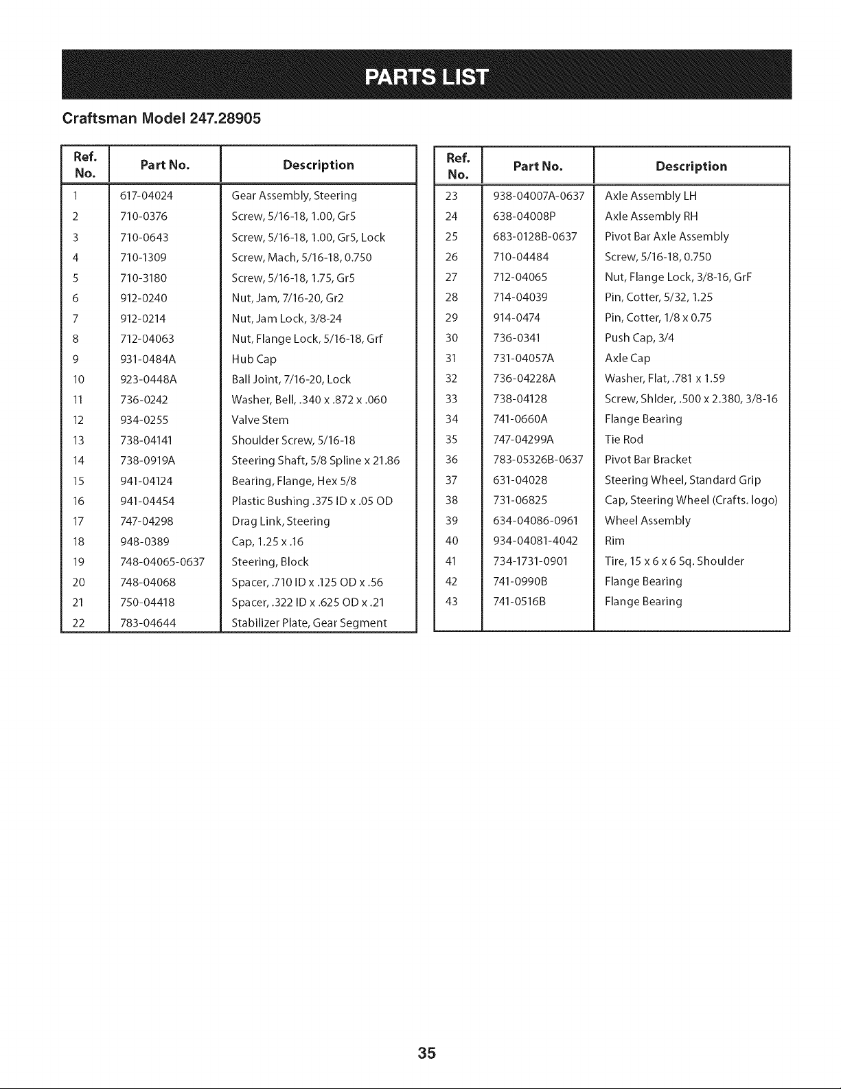
Craftsman Model 247.28905
Ref, [
No,
1 617-04024
2 710-0376
3 710-0643
4 710-1309
5 710-3180
6 912-0240
7 912-0214
8 712-04063
9 931-0484A
10 923-0448A
II 736-0242
12 934-0255
13 738-04141
14 738-0919A
15 941-04124
16 941-04454
17 747-04298
18 948-0389
19 748-04065-0637
20 748-04068
21 750-04418
22 783-04644
Part No, Description
Gear Assembly, Steering
Screw, 5/16-18, 1.00, Gr5
Screw, 5/16-18, 1.00, Gr5, Lock
Screw, Mach, 5/16-18, 0.750
Screw, 5/16-18, 1.75, Gr5
Nut, Jam, 7/16-20, Gr2
Nut, Jam Lock, 3/8-24
Nut, Flange Lock, 5/16-18, Grf
Hub Cap
Ball Joint, 7/16-20, Lock
Washer, Bell, .340 x .872 x .060
Valve Stem
Shoulder Screw, 5/16-18
Steering Shaft, 5/8 Spline x 21.86
Bearing, Flange, Hex 5/8
Plastic Bushing .375 ID x .05 OD
Drag Link, Steering
Cap, 1.25 x .16
Steering, Block
Spacer, .710 ID x .125 OD x .56
Spacer, .322 ID x .625 OD x .21
Stabilizer Plate, Gear Segment
Ref, I
No,
23 938-04007A-0637
24 638-04008P
25 683-0128B-0637
26 710-04484
27 712-04065
28 714-04039
29 914-0474
30 736-0341
31 731-04057A
32 736-04228A
33 738-04128
34 741-0660A
35 747-04299A
36 783-05326B-0637
37 631-04028
38 731-06825
39 634-04086-0961
40 934-04081-4042
41 734-1731-0901
42 741-0990B
43 741-0516B
Part No, Description
Axle Assembly LH
Axle Assembly RH
Pivot Bar Axle Assembly
Screw, 5/16-18, 0.750
Nut, Flange Lock, 3/8-16, GrF
Pin, Cotter, 5/32, 1.25
Pin, Cotter, 1/8 x 0.75
Push Cap, 3/4
Axle Cap
Washer, Flat, .781 x 1.59
Screw, Shlder, .500 x 2.380, 3/8-16
Flange Bearing
Tie Rod
Pivot Bar Bracket
Steering Wheel, Standard Grip
Cap, Steering Wheel (Crafts. logo)
Wheel Assembly
Rim
Tire, 15 x6x6 Sq. Shoulder
Flange Bearing
Flange Bearing
35
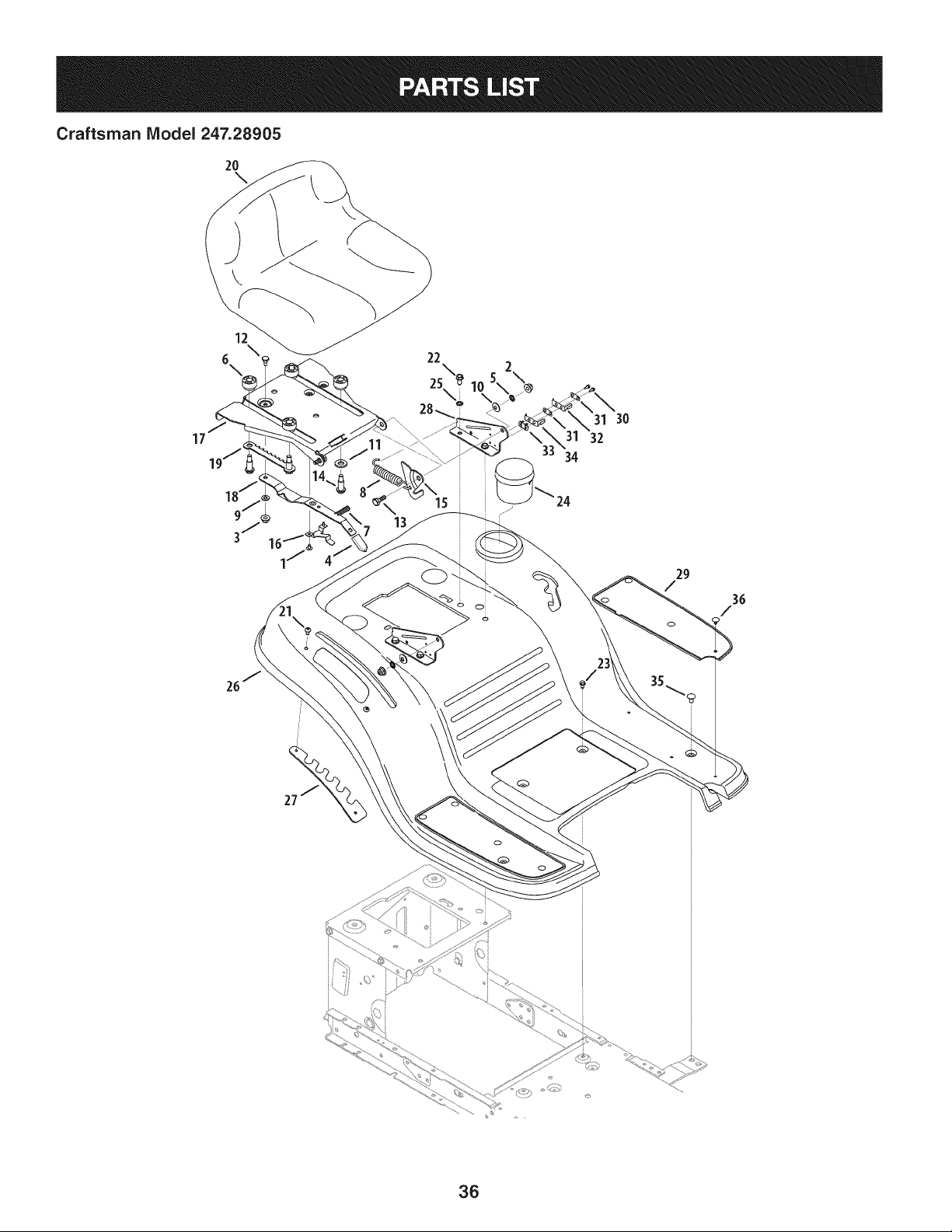
Craftsman Model 247.28905
2o
12
6, 22
2S\
28..
31 30
17 32
15
oi
29
/
3G
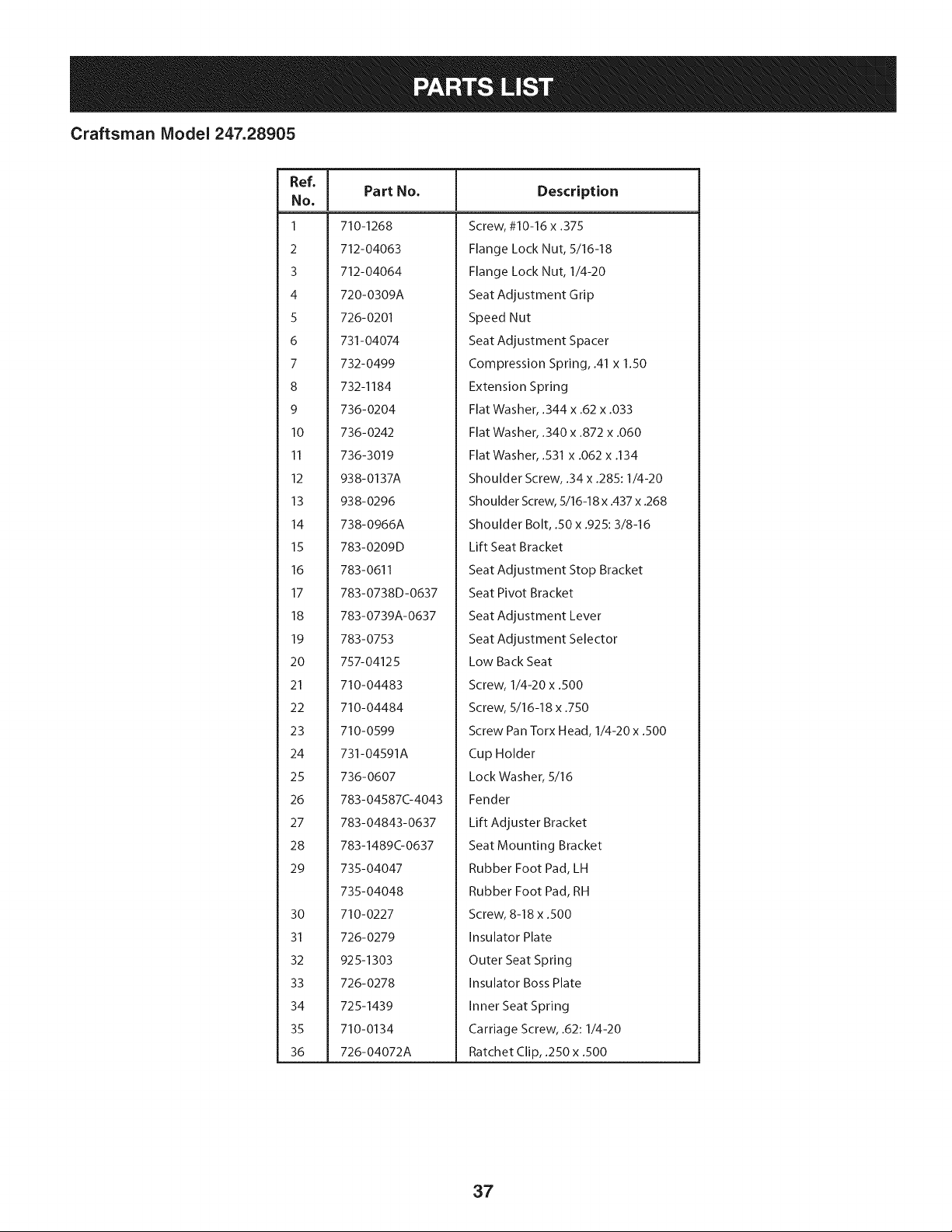
Craftsman Model 247.28905
Ref, [
No,
1 710-1268
2 712-04063
3 712-04064
4 720-0309A
5 726-0201
6 731-04074
7 732-0499
8 732-1184
9 736-0204
10 736-0242
II 736-3019
12 938-0137A
13 938-0296
14 738-0966A
15 783-0209D
16 783-0611
17 783-0738D-0637
18 783-0739A-0637
19 783-0753
20 757-04125
21 710-04483
22 710-04484
23 710-0599
24 731-04591A
25 736-0607
26 783-04587C-4043
27 783-04843-0637
28 783-1489G0637
29 735-04047
735-04048
30 710-0227
31 726-0279
32 925-1303
33 726-0278
34 725-1439
35 710-0134
36 726-04072A
Part No, Description
Screw, #10-16 x .375
Flange Lock Nut, 5/16-18
Flange Lock Nut, 1/4-20
Seat Adjustment Grip
Speed Nut
Seat Adjustment Spacer
Compression Spring, .41 x 1.50
Extension Spring
Flat Washer, .344 x .62 x .033
Flat Washer, .340 x .872 x .060
Flat Washer, .531 x .062 x .134
Shoulder Screw, .34 x .285:1/4-20
Shoulder Screw, 5/16-18 x .437 x .268
Shoulder Bolt, .50 x .925:3/8-16
Lift Seat Bracket
Seat Adjustment Stop Bracket
Seat Pivot Bracket
Seat Adjustment Lever
Seat Adjustment Selector
Low Back Seat
Screw, 1/4-20 x .500
Screw, 5/16-18 x .750
Screw Pan Torx Head, 1/4-20 x .500
Cup Holder
Lock Washer, 5/16
Fender
Lift Adjuster Bracket
Seat Mounting Bracket
Rubber Foot Pad, LH
Rubber Foot Pad, RH
Screw, 8-18 x .500
Insulator Plate
Outer Seat Spring
Insulator Boss Plate
Inner Seat Spring
Carriage Screw, .62:1/4-20
Ratchet Clip, .250 x .500
37
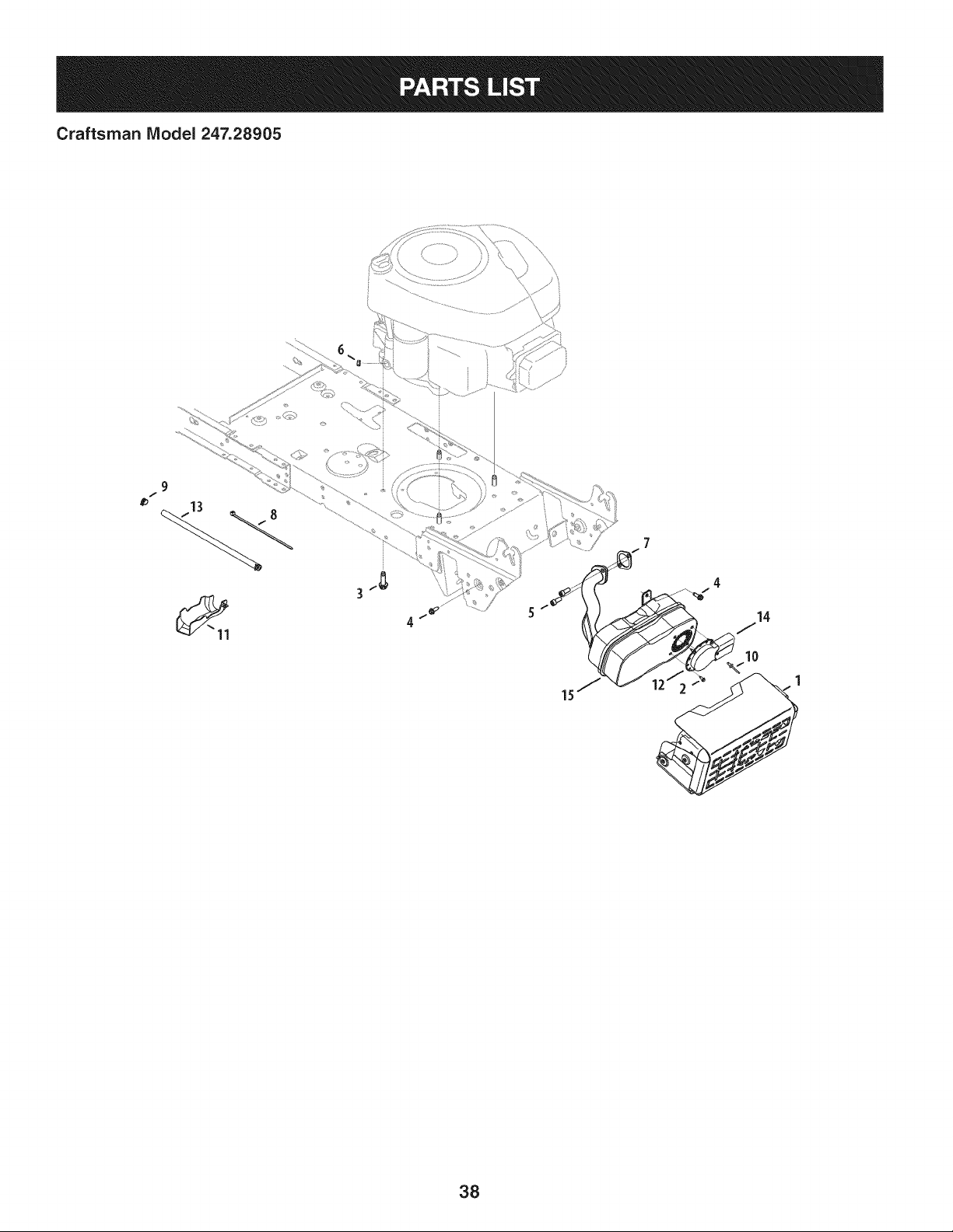
Craftsman IViodel 247.28905
9
f
4
7
4
14
10
1
38
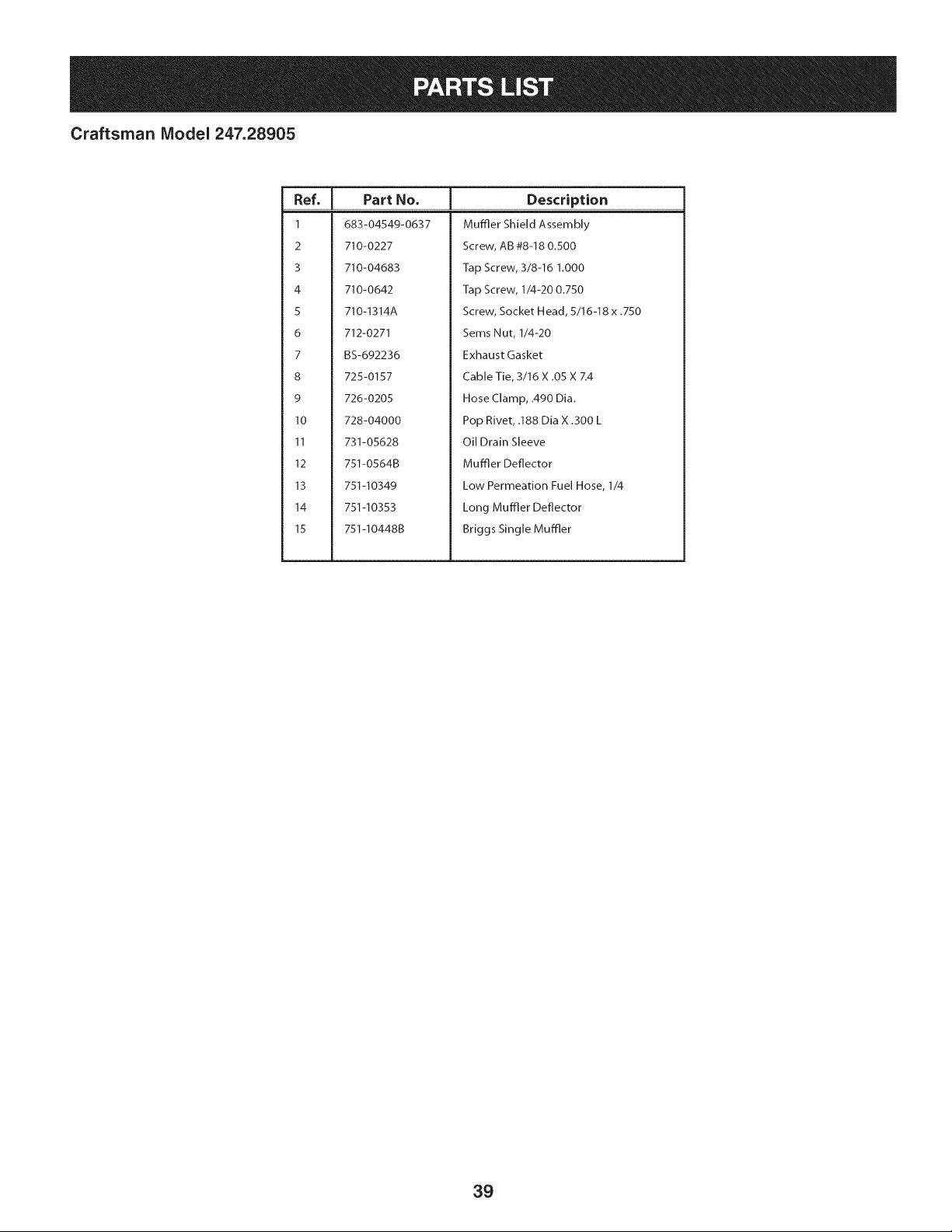
Craftsman Model 247.28905
I
Ref.
I Part No.
1 683-04549-0637
2 710-0227
3 710-04683
4 710-0642
5 710-1314A
6 712-0271
7 BS-692236
8 725-0157
9 726-0205
10 728-04000
11 731-05628
12 751-0564B
13 751-10349
14 751-10353
15 751-I0448B
Description
Muffler Shield Assembly
Screw, A8 #8-18 0.500
Tap Screw, 3/8-16 1.000
Tap Screw, 1/4-20 0.750
Screw, Socket Head, 5/16-18 x .750
Sems Nut, 1/4-20
Exhaust Gasket
Cable Tie, 3/16 X .05 X Z4
Hose Clamp, .490 Dia.
Pop Rivet, .188 Dia X .300 L
Oil Drain Sleeve
Muffler Deflector
Low Permeation Fuel Hose, 1/4
Long Muffler Deflector
Briggs Single Muffler
39
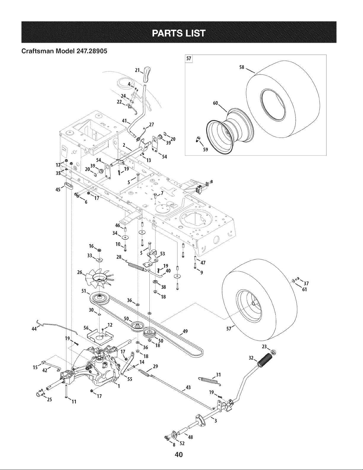
Craftsman Model 247.28905
11
49
29
31
_37
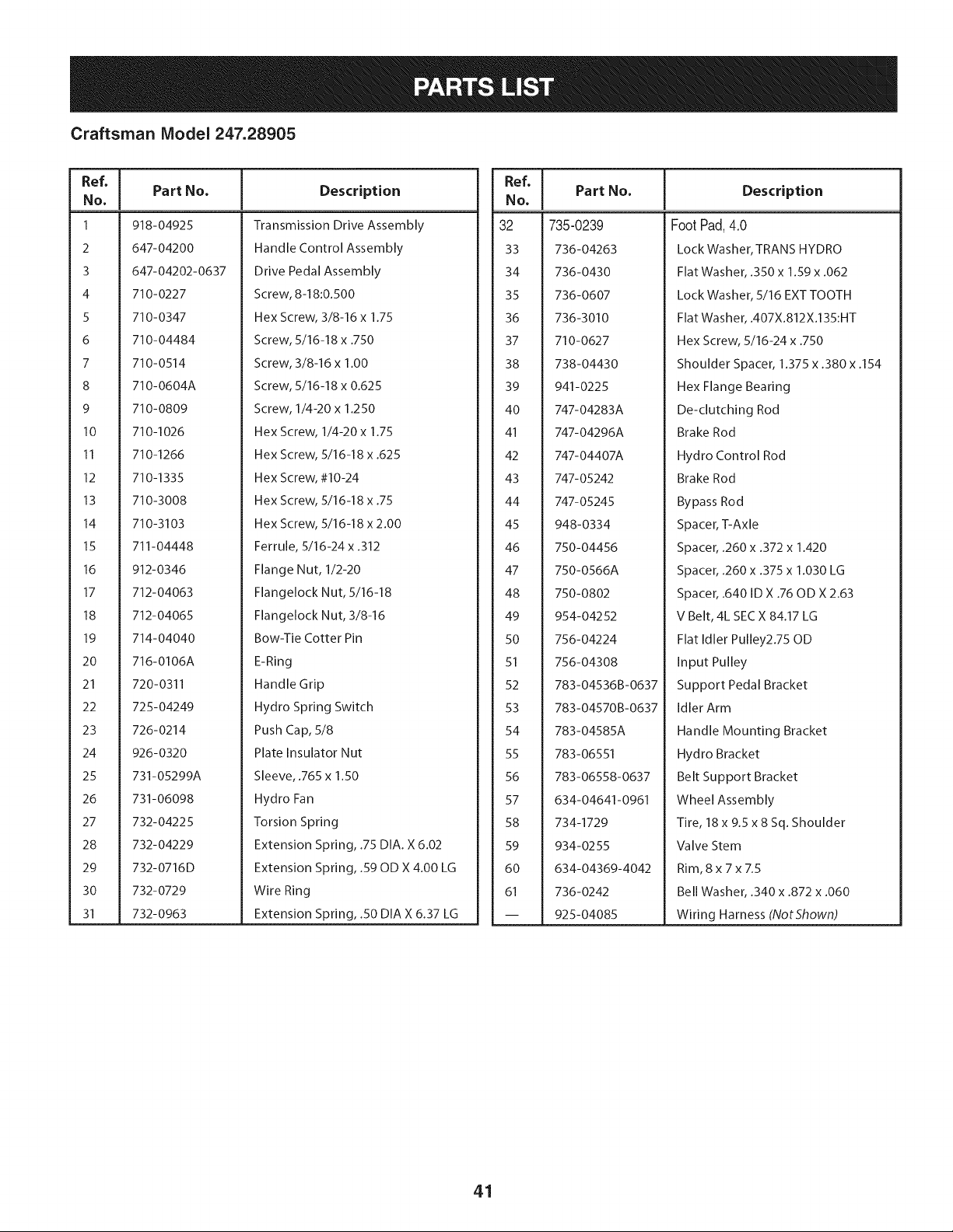
Craftsman Model 247.28905
Ref, [
No,
1 918-04925
2 647-04200
3 647-04202-0637
4 710-0227
5 710-0347
6 710-04484
7 710-0514
8 710-0604A
9 710-0809
10 710-1026
11 710-1266
12 710-1335
13 710-3008
14 710-3103
15 711-04448
16 912-0346
17 712-04063
18 712-04065
19 714-04040
20 716-0106A
21 720-0311
22 725-04249
23 726-0214
24 926-0320
25 731-05299A
26 731-06098
27 732-04225
28 732-04229
29 732-0716D
30 732-0729
31 732-0963
Part No, Description
Transmission Drive Assembly
Handle Control Assembly
Drive Pedal Assembly
Screw, 8-18:0.500
Hex Screw, 3/8-16 x 1.75
Screw, 5/16-18 x .750
Screw, 3/8-16 x 1.00
Screw, 5/16-18 x 0.625
Screw, 1/4-20 x 1.250
Hex Screw, 1/4-20 x 1.75
Hex Screw, 5/16-18 x .625
Hex Screw, #10-24
Hex Screw, 5/16-18 x .75
Hex Screw, 5/16-18 x 2.00
Ferrule, 5/16-24 x .312
Flange Nut, 1/2-20
Flangelock Nut, 5/16-18
Flangelock Nut, 3/8-16
Bow-Tie Cotter Pin
E-Ring
Handle Grip
Hydro Spring Switch
Push Cap, 5/8
Plate Insulator Nut
Sleeve, .765 x 1.50
Hydro Fan
Torsion Spring
Extension Spring, .75 DIA. X 6.02
Extension Spring, .59 OD X 4.00 LG
Wire Ring
Extension Spring, .50 DIA X 6.37 LG
Ref, ]
NO.
32 735-0239
33 736-04263
34 736-0430
35 736-0607
36 736-3010
37 710-0627
38 738-04430
39 941-0225
40 747-04283A
41 747-04296A
42 747-04407A
43 747-05242
44 747-05245
45 948-0334
46 750-04456
47 750-0566A
48 750-0802
49 954-04252
50 756-04224
51 756-04308
52 783-04536B-0637
53 783-04570B-0637
54 783-04585A
55 783-06551
56 783-06558-0637
57 634-04641-0961
58 734-1729
59 934-0255
60 634-04369-4042
61 736-0242
-- 925-04085
Part No, Description
FootPad,4.0
Lock Washer, TRANS HYDRO
Flat Washer, .350 x 1.59 x .062
Lock Washer, 5/16 EXT TOOTH
Flat Washer, .407X.812X.135:HT
Hex Screw, 5/16-24 x .750
Shoulder Spacer, 1.375 x .380 x .154
Hex Flange Bearing
De-clutching Rod
Brake Rod
Hydro Control Rod
Brake Rod
Bypass Rod
Spacer, T-Axle
Spacer, .260 x .372 x 1.420
Spacer, .260 x .375 x 1.030 LG
Spacer, .640 ID X .76 OD X 2.63
V Belt, 4L SECX 84.17 LG
Flat Idler Pulley2.75 OD
Input Pulley
Support Pedal Bracket
Idler Arm
Handle Mounting Bracket
Hydro Bracket
Belt Support Bracket
Wheel Assembly
Tire, 18 x 9.5 x 8 Sq. Shoulder
Valve Stem
Rim, 8x7xZ5
Bell Washer, .340 x .872 x .060
Wiring Harness (NotShown)
41
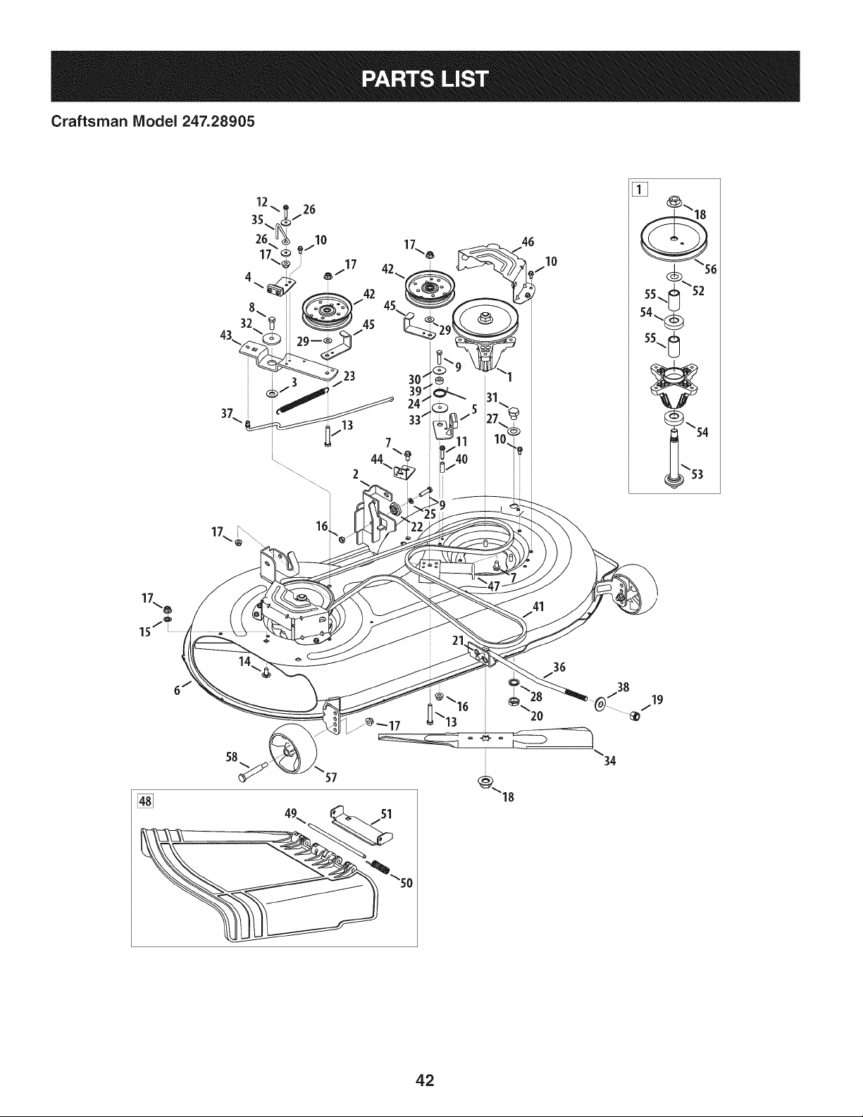
Craftsman IViodel 247.28905
58
57
[]
\50
41
38
34
42

Craftsman Model 247.28905
Ref, I
No,
1 918-04822A
2 683-0254B-0637
3 936-0344
4 983-04511
5 983-04525
6 983-04572-0637
7 710-04484
8 710-0514
9 710-0528
10 710-0599
11 710-0778
12 710-0809
13 710-3144
14 710-3178
15 712-0229
16 712-04063
17 712-04065
18 712-0417A
19 712-04243
20 912-0641
21 714-04043
22 917-04074
23 932-0384
24 732-04727
25 936-0119
26 936-0176
27 736-0187
28 736-0225
29 736-0262
Part No. Description
Spindle Pulley Assembly
Deck Hanger Bracket Assembly
Wash, Flat, .385 x 1.0 x .030
Brake Assembly
Brake Assembly
Deck
Screw, 5/16-18 x .750
Screw, 3/8-16 x 1.00
Hex Screw, 5/16-18 x 1.25
Screw, 1/4-20 x .500
Screw, 1/4-20 x 1.50
Screw, 1/4-20 x 1.250
Hex Head Screw, 3/8-16
Carriage Bolt, 3/8-16 x .75
Push Nut, 3/8
Flangelock Nut, 5/16-18
Flangelock Nut, 3/8-16
Flange Nut, 5/8-18
Flangelock Nut, 1/2-13
Hex Nut, M16- 1.5
Cotter Pin, Bow-Tie
Deck Adjuster Gear
Extension Spring, .62 x 6.12
Torsion Spring, 1.0x 1.17
Lock Washer, 5/16
Flat Washer, .265 x 9.38 x .120
Flat Washer, .64 x 1.24 x .06
Flat Washer, .5/8 Int. Tth.
Flat Washer, .385 x .870 x .092
Ref, I
No,
30 736-0362
31 738-04146
32 738-04162A
33 738-04166
34 942-04308
35 747-04530
36 747-04944B
37 747-05105
38 748-04069
39 750-0258
40 750-0566A
41 954-04060B
42 756-04129B
43 783-05946
44 783-06243-0637
45 783-06368-0637
46 783-06424A-0637
47 783-06643-0637
48 631-04460
49 711-04847A
50 732-04372
51 783-06074A
52 936-0351
53 738-1186A
54 941-0919
55 750-04936
56 956-1227
57 734-04155
58 938-3056
Part No. Description
Flat Washer, .330 x 1.25 x .06
Bolt Plug, M16 x 1.5
Shoulder Spacer, .8840 x .190
Shoulder Spacer, .5000 x .1475
Cutting Blade, 21.23": 2 in 1
Belt Keeper Rod
Deck Lift Rod
Brake Control Rod
Deck Lift Pivot Cup
Spacer
Spacer
V-Type Belt, 96.5
Idler Pulley, 4.25 Diameter
Idler Pivot Bracket
Deck Cable Engagement Bracket
Belt Pulley Guard
Deck Belt Cover
Deck Support Bracket
Chute Deflector Assembly
Hinge Pin
Torsion Spring, .44 x 2.0
Chute Bracket
Flat Washer, .760 x 1.50
Spindle Shaft
Ball Bearing, .787 x 1.85 x .551
Spacer, .792 x 1.060 x 1.860
Spindle Pulley
Deck Wheel, 5" Dia. Ball
Shoulder Bolt, 3/8-16
43
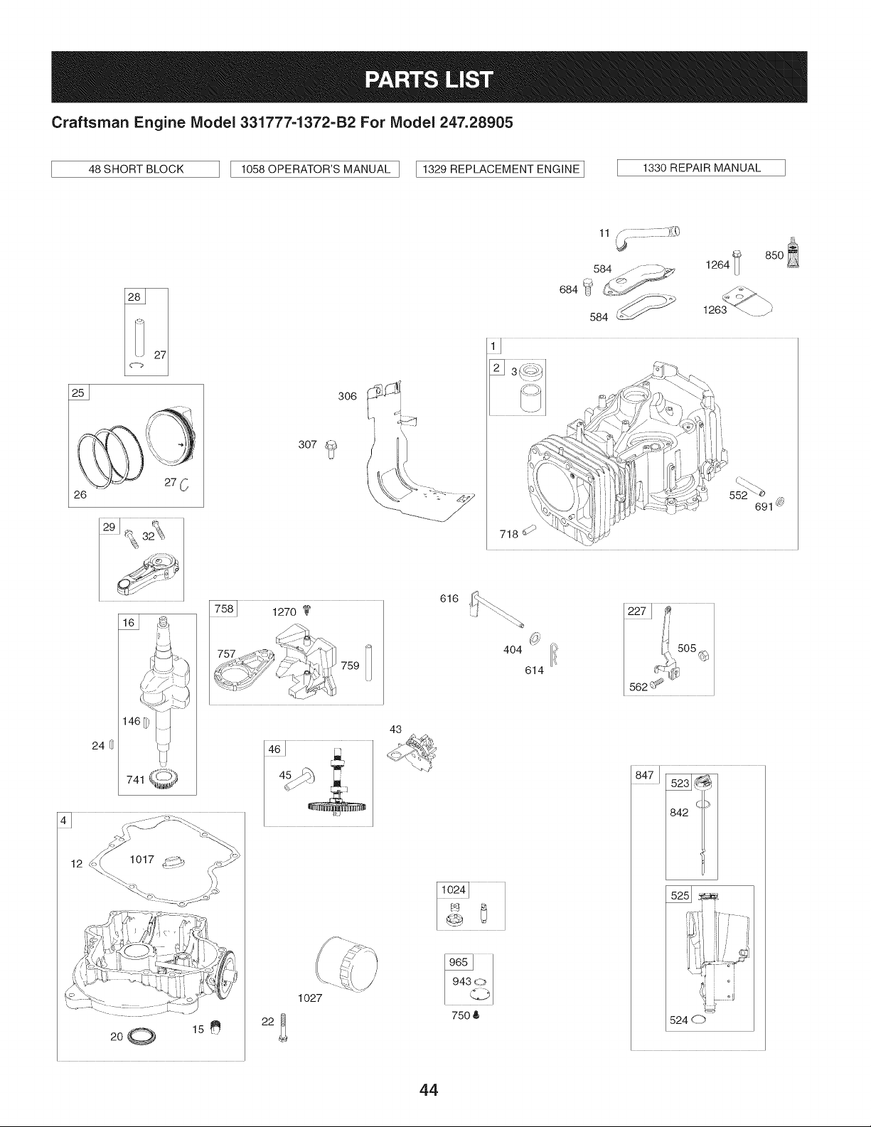
Craftsman Engine IViodel 331777=1372=B2 For IViodel 247.28905
46S.ORTBLOCK ] I 1056OPERATOR'SMANUALI [1329REPLAOEMENTENGINEI
1330 REPAIR MANUAL
_.._
85o
584 .........__.__ 1264
684 _-_ _"
1263 _ j"
26
306
307 _L_
i
_'_: ,,_&,..-%
718 d_-_%_
46
24 ¢
759
12
200 15
22_
1o27
43
616 _
4O4
614
x.
750 6
8471
842 '1/
524 d_')
44
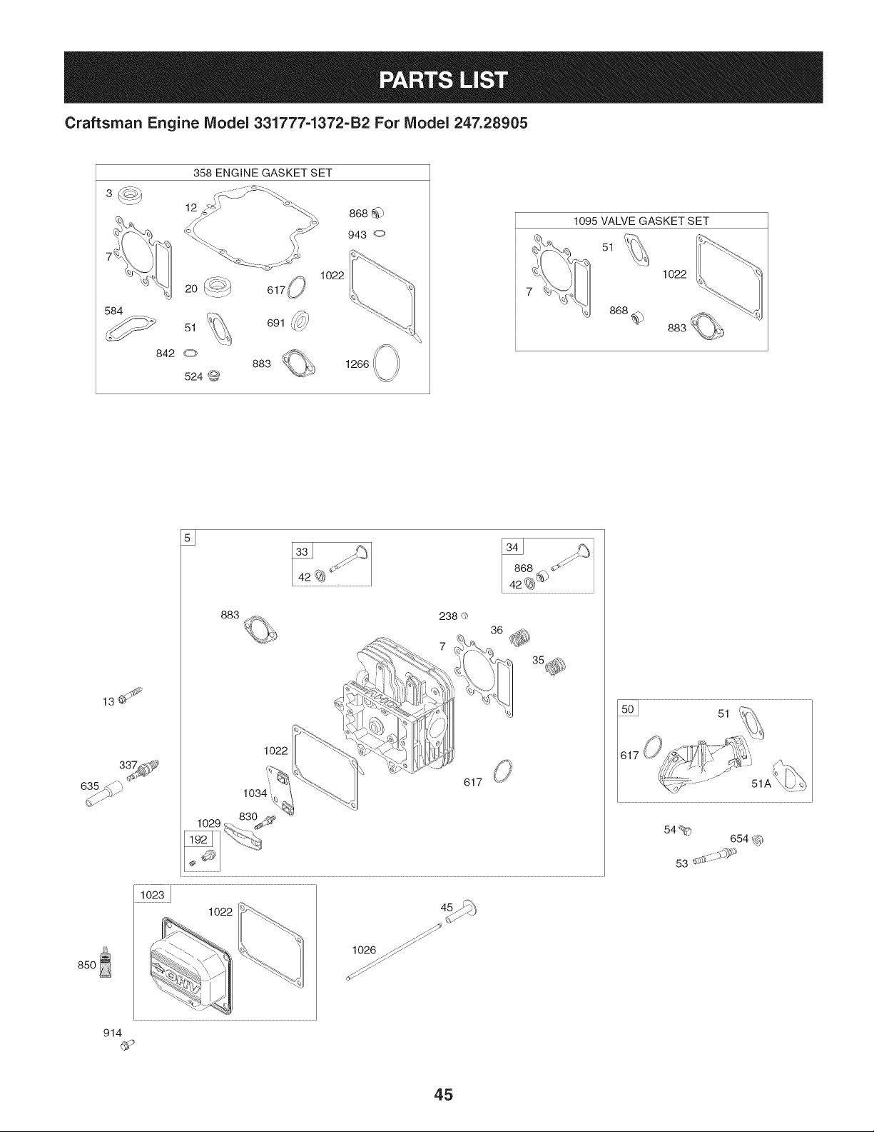
Craftsman Engine IViodel 331777=1372=B2 For IViodel 247.28905
3_
20
584
_ 51
842 C;_
358 ENGINE GASKET SET
524
868 @
943 o
1022
1095 VALVE GASKET SET
51
1022
868f_
13_
85O
883
238 Q
1022
617
¸1023111111
1022
, 1026 ._
914
617
54%
654 ,_)_
45
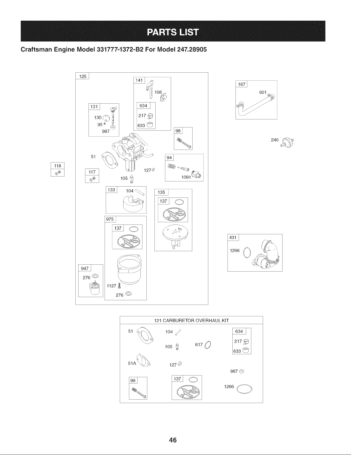
Craftsman Engine IViodel 331777-1372-B2 For IViodel 247.28905
51
127c_
105
33 104
87 601
51
121 CARBURETOR OVERHAUL KiT
104
105 _ 617 _'
987 (o)
1266 _
46
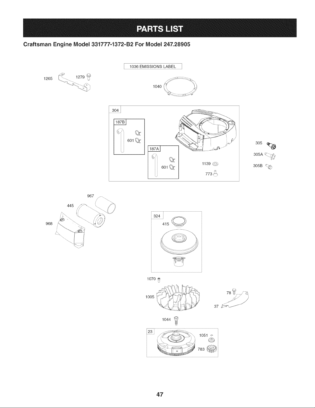
Craftsman Engine Model 331777=1372=B2 For Model 247.28905
1036 EMiSSiONS LABEL
1265
1040 _<: ......._d::_
1139 d?_
601 _.._
305
305A .....;7>
305B _,;'_
968
445
967
324....... -%
415 .......
,\. _)
1070
1005
¢-:4
37 __
1o44
_-_ "-/)Z_:-_%,_ lO51_,.
_:,/ ..................V_./A _,__
................................_-_'T ..................................................................
47
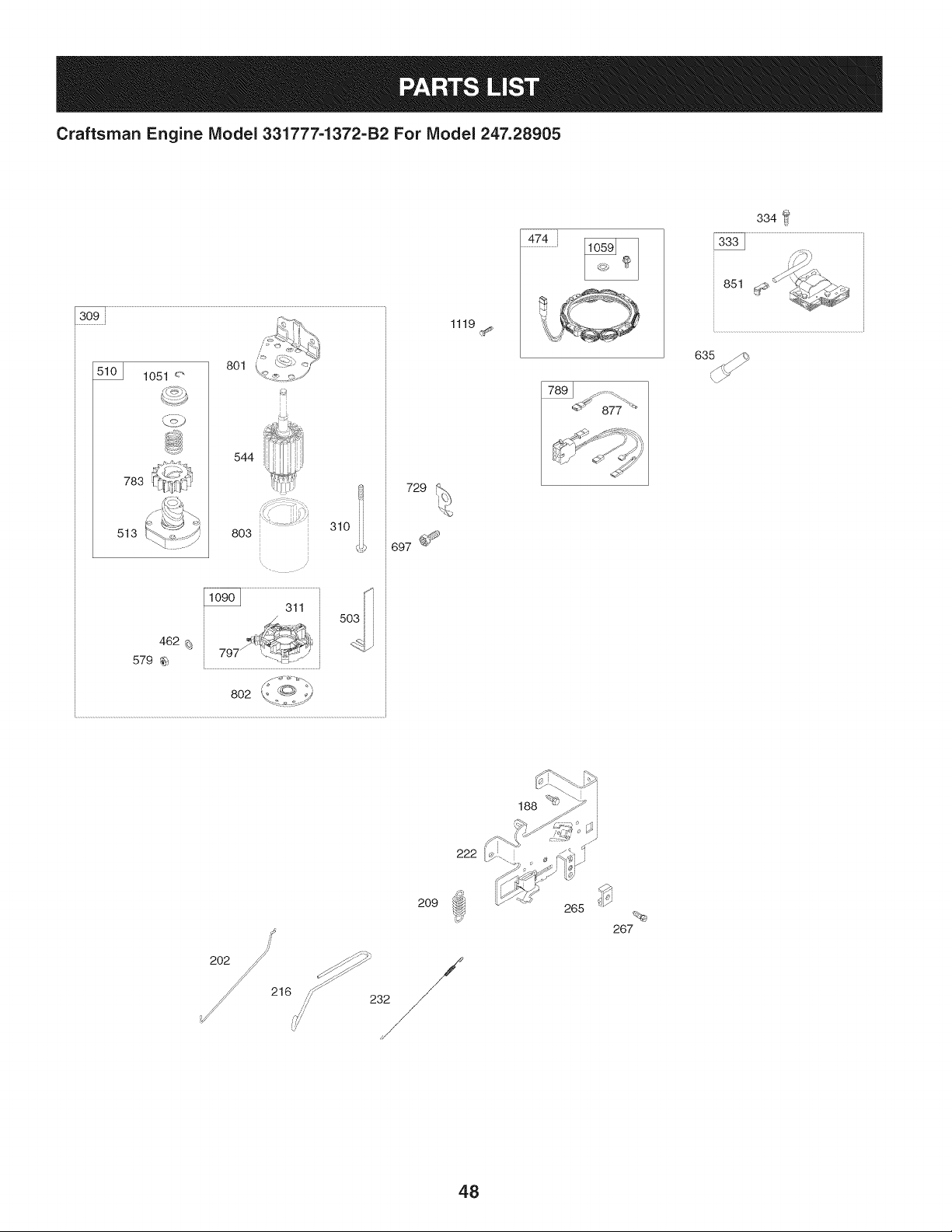
Craftsman Engine Model 331777-1372-B2 For Model 247.28905
783
513
801
544
310
803
G>
729
1119
334
851
209
/
/
/
/
265
267
48
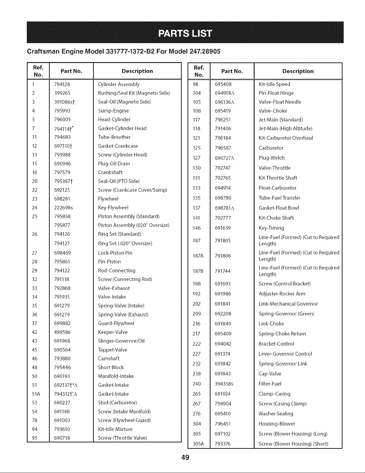
Craftsman Engine Model 331777=1372=B2 For Model 247.28905
Ref, [
No,
1 794128
2 399265
3 391086si
4 795993
5 796005
7 794114_*
II 794683
12 6971101
13 793988
15 690946
16 797579
20 795387_
22 692125
23 698281
24 222698s
25 795858
795877
26 794126
794127
27 698469
28 795861
29 794122
32 791118
33 792868
34 791935
35 691279
36 691279
37 699882
42 499586
43 691968
45 690564
46 793880
48 795446
50 690193
51 6921371"A
51A 7943125"A
53 690227
54 691148
78 691003
94 793610
95 690718
Part No, Description
Cylinder Assembly
Bushing/Seal Kit (Magneto Side)
Seal-Oil (Magneto Side)
Sump-Engine
Head-Cylinder
Gasket-Cylinder Head
Tube-Breather
Gasket-Crankcase
Screw (Cylinder Head)
Plug-Oil Drain
Crankshaft
Seal-Oil (PTOSide)
Screw (Crankcase Cover/Sump)
Flywheel
Key-Flywheel
Piston Assembly (Standard)
Piston Assembly (020" Oversize)
Ring Set (Standard)
Ring Set (.020" Oversize)
Lock-Piston Pin
Pin-Piston
Rod-Connecting
Screw (Connecting Rod)
Valve-Exhaust
Valve-Intake
Spring-Valve (Intake)
Spring-Valve (Exhaust)
Guard-Flywheel
Keeper-Valve
Slinger-Governor/Oil
Tappet-Valve
Camshaft
Short Block
Manifold-Intake
Gasket-Intake
Gasket-Intake
Stud (Carburetor)
Screw (Intake Manifold)
Screw (Flywheel Guard)
Kit-Idle Mixture
Screw (Throttle Valve)
Ref, Part No,
No,
98 695408
104 694918A
105 696136A
108 695419
117 796251
118 791406
121 796184
125 796587
127 690727A
130 792747
131 792765
133 694914
135 698780
137 698781A
141 792777
146 691639
187 791805
187A 791806
187B 791744
188 691693
192 691986
202 691841
209 692208
216 691840
217 695409
222 694042
227 691374
232 691842
238 691843
240 394358s
265 691024
267 794904
276 695410
304 796451
305 697102
305A 793376
Description
Kit-Idle Speed
Pin-Float Hinge
Valve-Float Needle
Valve-Choke
Jet-Main (Standard)
Jet-Main (High Altitude)
Kit-Carburetor Overhaul
Carburetor
Plug-Welch
Valve-Throttle
Kit-Throttle Shaft
Float-Ca rburetor
Tube-Fuel Transfer
Gasket-Float Bowl
Kit-Choke Shaft
Key-Timing
Line-Fuel (Formed) (Cut to Required
Length)
Line-Fuel (Formed) (Cut to Required
Length)
Line-Fuel (Formed) (Cut to Required
Length)
Screw (Control Bracket)
Adjuster-Rocker Arm
Link-Mechanical Governor
Spring-Governor (Green)
Link-Choke
Spring-Choke Return
Bracket-Control
Lever-Governor Control
Spring-Governor Link
Cap-VaIve
Filter-Fuel
Clamp-Casing
Screw (Casing Clamp)
Washer-Sealing
Housing-Blower
Screw (Blower Housing) (Long)
Screw (Blower Housing) (Short)
49
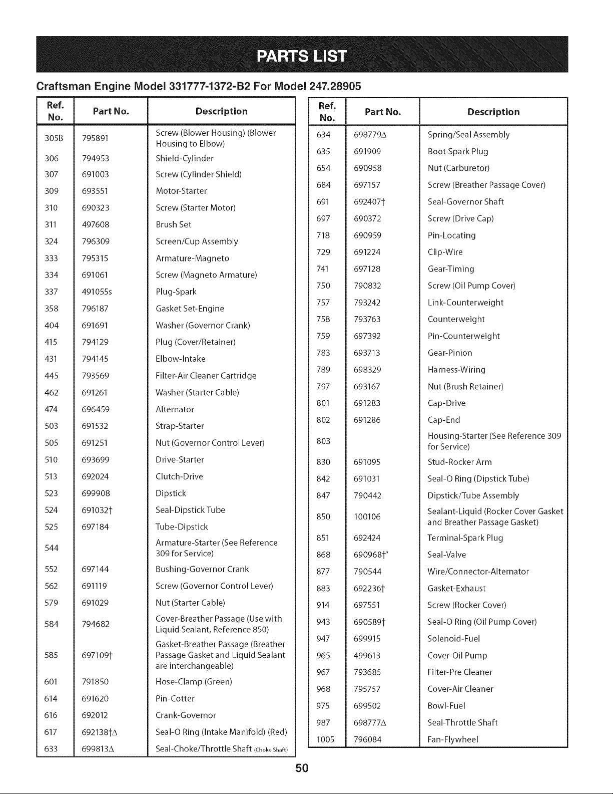
Craftsman Engine Model 331777-1372-B2 For Model 247.28905
Ref, Part No. Description Ref, [
No. No.
[
305B 795891
306 794953
307 691003
309 693551
310 690323
311 497608
324 796309
333 795315
334 691061
337 491055s
358 796187
404 691691
415 794129
431 794145
445 793569
462 691261
474 696459
503 691532
505 691251
510 693699
513 692024
523 699908
524 691032t
525 697184
544
552 697144
562 691119
579 691029
584 794682
585 697109t
601 791850
614 691620
616 692012
617 6921381A
633 699813A
Screw (Blower Housing) (Blower
Housing to Elbow)
Shield-Cylinder
Screw (Cylinder Shield)
Motor-Starter
Screw (Starter Motor)
Brush Set
Screen/Cup Assembly
Armature-Magneto
Screw (Magneto Armature)
Plug-Spark
Gasket Set-Engine
Washer (Governor Crank)
Plug (Cover/Retainer)
Elbow-Intake
Filter-Air Cleaner Cartridge
Washer (Starter Cable)
Alternator
Stra p-Starter
Nut (Governor Control Lever)
Drive-Starter
Clutch-Drive
Dipstick
Seal-Dipstick Tube
Tube-Dipstick
Armature-Starter (See Reference
309 for Service)
Bushing-Governor Crank
Screw (Governor Control Lever)
Nut (Starter Cable)
Cover-Breather Passage (Use with
Liquid Sealant, Reference 850)
Gasket-Breather Passage (Breather
Passage Gasket and Liquid Sealant
are interchangeable)
Hose-Clamp (Green)
Pin-Cotter
Crank-Governor
SeaI-O Ring (Intake Manifold) (Red)
Seal-Choke/Throttle Shaft (ChokeShaft)
634
635
654
684
691
697
718
729
741
750
757
758
759
783
789
797
801
8O2
803
830
842
847
85O
851
868
877
883
914
943
947
965
967
968
975
987
1005
Part No. Description
698779A
691909
690958
697157
692407t
690372
690959
691224
697128
790832
793242
793763
697392
693713
698329
693167
691283
691286
691095
691031
790442
100106
692424
690968t*
790544
692236t
697551
690589t
699915
499613
793685
795757
699502
698777A
796084
Spring/Seal Assembly
Boot-Spark Plug
Nut (Carburetor)
Screw (Breather Passage Cover)
Seal-Governor Shaft
Screw (Drive Cap)
Pin-Locating
Clip-Wire
Gear-Timing
Screw (Oil Pump Cover)
Link-Counterweight
Counterweight
Pin-Counterweight
Gear-Pinion
Harness-Wiring
Nut (Brush Retainer)
Cap-Drive
Cap-End
Housing-Starter (See Reference 309
for Service)
Stud-Rocker Arm
SeaI-O Ring (Dipstick Tube)
Dipstick/Tube Assembly
Sealant-Liquid (Rocker Cover Gasket
and Breather Passage Gasket)
Terminal-Spark Plug
Seal-Valve
Wire/Connector-Alternator
Gasket-Exhaust
Screw (Rocker Cover)
SeaI-O Ring (Oil Pump Cover)
Solenoid-Fuel
Cover-Oil Pump
Filter-Pre Cleaner
Cover-Air Cleaner
Bowl-Fuel
Seal-Throttle Shaft
Fan-Flywheel
50
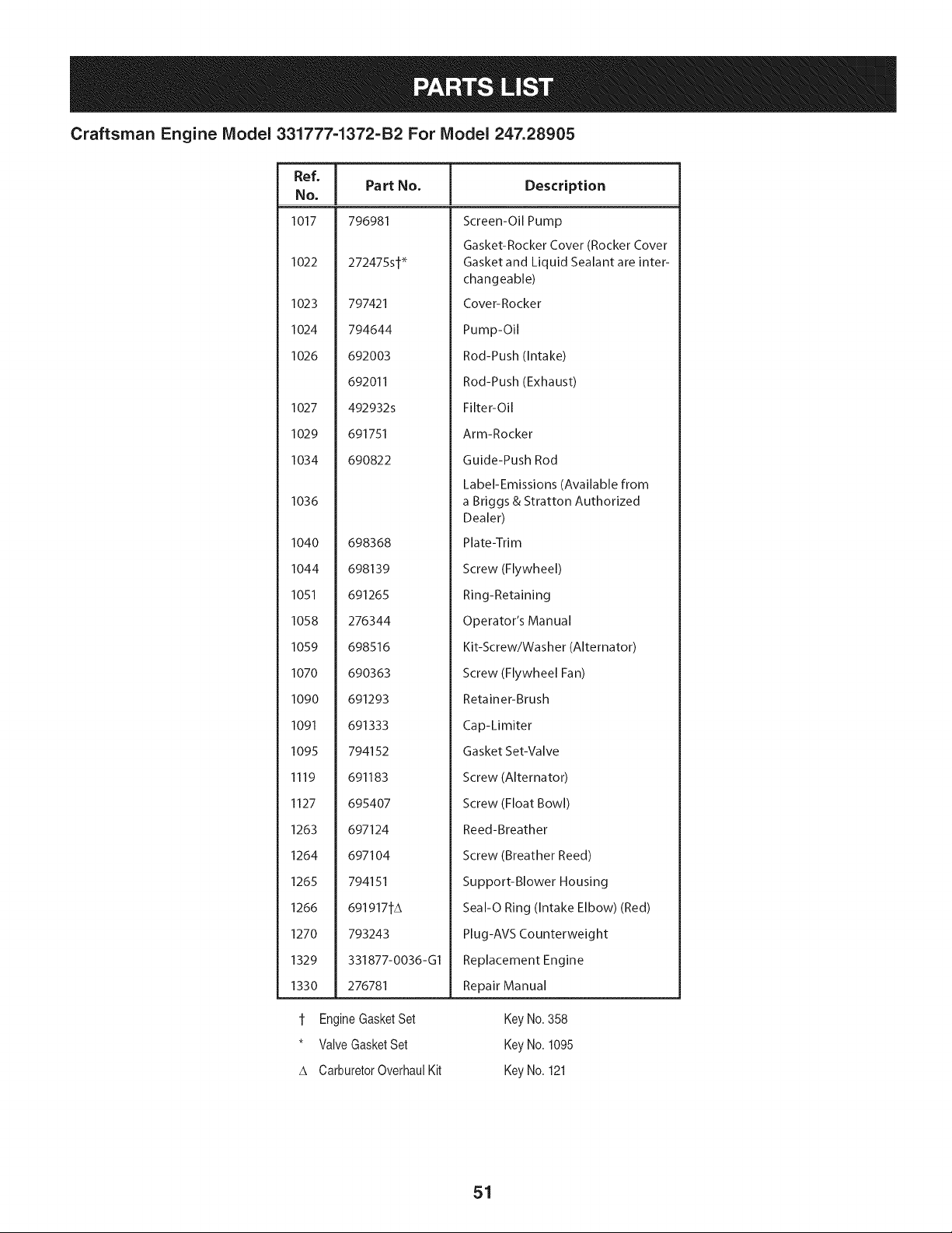
Craftsman Engine Model 331777-1372-B2 For Model 247.28905
Ref, Part No.
NO,
1017 796981
1022 272475st _
1023 797421
1024 794644
1026 692003
692011
1027 492932s
1029 691751
1034 690822
1036
1040 698368
1044 698139
1051 691265
1058 276344
1059 698516
1070 690363
1090 691293
1091 691333
1095 794152
1119 691183
1127 695407
1263 697124
1264 697104
1265 794151
1266 691917tA
1270 793243
1329 331877-0036-G1
1330 276781
t Engine GasketSet
* Valve Gasket Set
A Carburetor OverhauI Kit
Description
Screen-Oil Pump
Gasket-Rocker Cover (Rocker Cover
Gasket and Liquid Sealant are inter-
changeable)
Cover-Rocker
Pump-Oil
Rod-Push (Intake)
Rod-Push (Exhaust)
Filter-Oil
Arm-Rocker
Guide-Push Rod
Label-Emissions (Available from
a Briggs & Stratton Authorized
Dealer)
Plate-Trim
Screw (Flywheel)
Ring-Retaining
Operator's Manual
Kit-Screw/Washer (Alternator)
Screw (Flywheel Fan)
Retainer-Brush
Cap-Limiter
Gasket Set-Valve
Screw (Alternator)
Screw (Float Bowl)
Reed-Breather
Screw (Breather Reed)
Support-Blower Housing
Seal-O Ring (Intake Elbow) (Red)
Plug-AVS Counterweight
Replacement Engine
Repair Manual
Key No. 358
Key No. 1095
Key No. 121
51

This page intentionally left blank. Use this page to make any notes regarding your tractor.
52

This page intentionally left blank. Use this page to make any notes regarding your tractor.
53
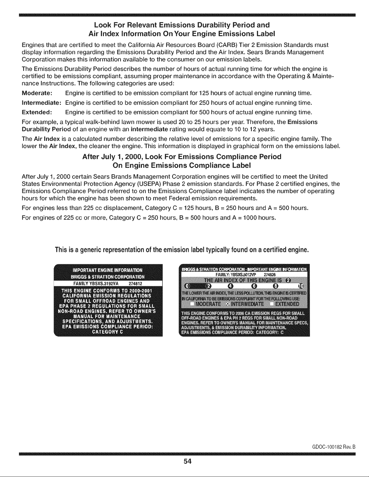
Look For Relevant Emissions Durability Period and
Air index information On Your Engine Emissions Label
Engines that are certified to meet the California Air Resources Board (CARB) Tier 2 Emission Standards must
display information regarding the Emissions Durability Period and the Air Index. Sears Brands Management
Corporation makes this information available to the consumer on our emission labels.
The Emissions Durability Period describes the number of hours of actual running time for which the engine is
certified to be emissions compliant, assuming proper maintenance in accordance with the Operating & Mainte-
nance Instructions. The following categories are used:
Moderate: Engine is certified to be emission compliant for 125 hours of actual engine running time.
Intermediate: Engine is certified to be emission compliant for 250 hours of actual engine running time.
Extended: Engine is certified to be emission compliant for 500 hours of actual engine running time.
For example, a typical walk-behind lawn mower is used 20 to 25 hours per year. Therefore, the Emissions
Durability Period of an engine with an intermediate rating would equate to 10 to 12 years.
The Air index is a calculated number describing the relative level of emissions for a specific engine family. The
lower the Air Index, the cleaner the engine. This information is displayed in graphical form on the emissions label.
After July 1,2000, Look For Emissions Compliance Period
On Engine Emissions Compliance Label
After July 1, 2000 certain Sears Brands Management Corporation engines will be certified to meet the United
States Environmental Protection Agency (USEPA) Phase 2 emission standards. For Phase 2 certified engines, the
Emissions Compliance Period referred to on the Emissions Compliance label indicates the number of operating
hours for which the engine has been shown to meet Federal emission requirements.
For engines less than 225 cc displacement, Category C = 125 hours, B = 250 hours and A = 500 hours.
For engines of 225 cc or more, Category C = 250 hours, B = 500 hours and A = 1000 hours.
This is a generic representation of the emission label typically found on a certified engine.
FAMILYYBSXS.3192VA 274812
GDOC-100182Rev.B
54
(Thispageapplicableinthe U.S.A.and Canadaonly.)
Sears Brands Management Corporation (Sears), the California Air Resources Board (CARD)
and the United States Environmental Protection Agency (U.S. EPA)
Emission Control System Warranty Statement (Owner's Defect Warranty Rights and Obligations)
EMISSIONCONTROLWARRANTYCOVERAGEISAPPLICABLETOCERTI-
FIEDENGINESPURCHASEDIN CALIFORNIAIN 1995ANDTHEREAF-
TER,WHICHARE USEDINCALIFORNIA,ANDTOCERTIFIEDMODEL
California and United States Emission
The CaliforniaAir ResourcesBoard(CARD),U.S.EPAand Searsare pleased
to explainthe EmissionControlSystemWarrantyon your modelyear2000and
latersmalloff-roadengine(SORE).InCalifornia,newsmall off-roadengines
mustbe designed,builtand equippedto meetthe State'sstringentanti-smog
standards.Elsewherein the UnitedStates,newnon-road,spark-ignition
enginescertifiedfor modelyear 1997and latermustmeetsimilar standardsset
forth bythe U.S.EPA.Sears mustwarranttheemissioncontrol systemon your
YEAR 1997ANDLATERENGINESWHICHARE PURCHASEDAND USED
ELSEWHEREIN THEUNITEDSTATES(ANDAFTERJANUARY1,2001 IN
CANADA).
Control Defects Warranty Statement
enginefor theperiodsoftime listedbelow,providedtherehas been noabuse,
neglector impropermaintenanceof your smalloff-roadengine.Youremis-
sion controlsystemincludespartssuch as the carburetor,air cleaner,ignition
system,mufflerand catalyticconverter.Also includedmaybe connectorsand
otheremissionrelatedassemblies.Wherea warrantableconditionexists,Sears
will repairyour smalloff-roadengineat no costto you includingdiagnosis,parts
and labor.
Sears Emission Control Defects Warranty Coverage
Smalloff-roadenginesarewarrantedrelativeto emissioncontrolpartsdefects
fora periodof one year,subjectto provisionsset forth below.Ifany covered
Owner's Warranty
Asthe smalloff-roadengine owner,you are responsiblefor the performanceof
therequiredmaintenancelistedin yourOperatingand MaintenanceInstruc-
tions.Searsrecommendsthatyou retain allyourreceiptscoveringmaintenance
on yoursmalloff-roadengine,butSears cannotdenywarrantysolelyfor the
lackof receiptsor for yourfailureto ensurethe performanceof all scheduled
maintenance.As the smalloff-roadengineowner,you shouldhoweverbe
awarethat Searsmay denyyou warrantycoverageif your smalloff-roadengine
ora part hasfaileddueto abuse,neglect,impropermaintenanceor unap-
parton yourengineis defective,the part will be repairedor replacedbySears.
Responsibilities
provedmodifications.Youare responsiblefor presentingyour smalloff-road
engineto an AuthorizedSearsServiceDealeras soonas a problemexists.The
undisputedwarrantyrepairsshouldbe completedin a reasonableamountof
time,not to exceed30 days. Ifyou haveany questionsregardingyourwarranty
rightsand responsibilities,you shouldcontacta SearsService Representative
at 1-800-469-4663.The emissionwarrantyis a defectswarranty.Defectsare
judgedon normalengineperformance.Thewarrantyis notrelatedto an in-use
emissiontest.
Sears Emission Control Defects Warranty Provisions
ThefollowingarespecificprovisionsrelativetoyourEmissionControlDefectsWarrantyCoverage.ItisinadditiontotheSearsenginewarrantyfornon-regulated
enginesfound in the Operatingand MaintenanceInstructions.
1. WarrantedParts
Coverageunderthis warrantyextendsonly to the parts listedbelow(the
emissioncontrolsystemsparts)to the extentthese partswere presenton
the engine purchased.
a. FuelMeteringSystem
• Cold start enrichmentsystem
• Carburetorand internalparts
• FuelPump
b. Air lnduction System
• Air cleaner
• Intakemanifold
c. IgnitionSystem
• Spark plug(s)
• Magnetoignitionsystem
d. CatalystSystem
• Catalyticconverter
• Exhaustmanifold
• Air injectionsystemor pulsevalve
e. MiscellaneousItemsUsedin AboveSystems
• Vacuum,temperature,position,timesensitivevalves
andswitches
• Connectorsandassemblies
2. Lengthof Coverage
Searswarrantsto the initialownerand eachsubsequentpurchaserthat
the WarrantedParts shallbe free from defects in materialsandworkman-
shipwhich causedthe failure of the WarrantedPartsfor a periodof one
yearfromthe datethe engineis deliveredto a retailpurchaser.
3. NoCharge
Repairor replacementof anyWarrantedPartwill be performedat no
chargeto the owner,includingdiagnosticlabor whichleadsto the
determinationthata WarrantedPartis defective,if the diagnosticwork is
performedat an AuthorizedSears ServiceDealer.Foremissionswarranty
servicecontact yournearestAuthorizedSears ServiceDealeras listed in
the "YellowPages"under"Engines,Gasoline,""GasolineEngines,""Lawn
Mowers,"or similarcategory.
4. Claimsand CoverageExclusions
Warrantyclaimsshall be filed in accordancewiththe provisionsof the
Sears EngineWarrantyPolicy.Warrantycoverageshall be excludedfor
failuresof WarrantedPartswhichare not original Sears partsor because
of abuse, neglector impropermaintenanceas setforth inthe Sears
EngineWarrantyPolicy.Sears is notliableto coverfailuresof Warranted
Partscausedby the use of add-on,non-original,or modifiedparts.
5. Maintenance
Any WarrantedPart whichis notscheduledfor replacementas required
maintenanceor whichis scheduledonly for regularinspectionto the effect
of "repairor replaceas necessary"shallbe warrantedasto defectsfor the
warrantyperiod.Any WarrantedPartwhich is scheduledfor replacement
as requiredmaintenanceshallbe warrantedasto defectsonly forthe
periodof time up to the firstscheduledreplacementfor that part. Any
replacementpart that is equivalentin performanceand durabilitymay
be usedin the performanceof any maintenanceor repairs.The owneris
responsibleforthe performanceof all requiredmaintenance,as definedin
the SearsOperatingand MaintenanceInstructions.
6. ConsequentialCoverage
Coveragehereundershallextend to the failure of any engine components
caused bythe failureof any WarrantedPartstill underwarranty.
Inthe USAandCanada,a 24 hour hotline, 1-800-469-4663,has a menu of pre-recordedmessagesofferingyou enginemaintenanceinformation.
GD0C-100188Rev.B
55
FEDERAL and/or CALIFORNIA EMISSION CONTROL WARRANTY STATEMENT
YOUR WARRANTY RIGHTS AND OBLIGATIONS
MTDConsumerGroupInc,the UnitedStatesEnvironmentalProtectionAgency (EPA),and, forthose productscertifiedfor sale in the stateof California,the
CaliforniaAir ResourcesBoard(CARB)are pleasedto explainthe emission(evaporativeand/or exhaust)controlsystem(ECS) warrantyon youroutdoor2006
andlater smalloff-roadspark-ignitedengine andequipment(outdoorequipmentengine)In California,new outdoorequipmentengines mustbe designed,built and
equippedto meetthe State'sstringentanti-smogstandards(in otherstates, 1997andlater modelyear equipmentmustbe designed,built,and equippedto meet
theU.S. EPAsmalloff-road, sparkignitionengine regulations.MTDConsumerGroupInc mustwarrantthe ECSon your outdoorequipmentenginefor the periodof
timelisted belowprovidedtherehas been no abuse, neglector impropermaintenanceof outdoor equipmentengine.
Your ECSmay includeparts such as thecarburetor,fuel-injectionsystem,the ignitionsystem,catalyticconverter,fuel tanks,fuel lines,fuel caps,valves,canisters,
filters,vapor hoses,clamps,connectors,andotherassociatedemission-relatedcomponents.
Wherea warrantableconditionexists, MTDConsumerGroupIncwill repairyouroutdoorequipmentengine at no cost to you includingdiagnosis,parts and labor.
MAN UFACTURER'S WARRANTY COVERAGE:
Thisemissioncontrolsystemis warrantedfor two years. If any emission-relatedpart on your outdoorequipmentengineis defective,the part will berepairedor
replacedby MTDCONSUMERGROUPINC.
OWNER'S WARRANTY RESPONSIBILITIES:
Asthe outdoorequipmentengineowner,you are responsiblefor performanceof the requiredmaintenancelisted inyour owner'smanual.MTDConsumerGroup
Inc recommendsthat you retain all receiptscoveringmaintenanceon youroutdoorequipmentengine,butMTDConsumerGroupInc cannotdeny warrantysolely
forthe lackof receipts.
Asthe outdoorequipmentengineowner,you shouldhoweverbe awarethat MTDConsumerGroupInc may denyyou warrantycoverageif your outdoorequipment
engineor a part has failed due to abuse, neglect,or impropermaintenanceor unapprovedmodifications.
Youare responsiblefor presentingyouroutdoorequipmentengineto MTDConsumerGroupInc'sdistributioncenterorservicecenteras soon asthe problem
exists.The warrantyrepairsshouldbecompletedin a reasonableamountof time, notto exceed30 days.If you havea questionregardingyour warrantycoverage,
you shouldcontactthe MTDConsumerGroupIncService Departmentat 1-800-800-7310or via emailat http://support.mtdproducts.com
GENERAL EMISSIONS WARRANTY COVERAGE:
MTDConsumerGroupIncwarrantsto the ultimatepurchaserand eachsubsequentpurchaserthat the outdoorequipmentengine is: Designed,built and equipped
so asto conformwithall applicableregulations;and freefromdefects in materialsand workmanshipthatcausethe failureof a warrantedpart to be identicalin all
materialrespectsto that part as describedin MTDConsumerGroup Inc'sapplicationfor certification.
The warrantyperiodbeginson the date the outdoorequipmentengineis deliveredto an ultimate purchaserorfirst placedinto service.The warrantyperiodis two
years.
Subjectto certain conditionsand exclusionsasstated below,the warrantyon emission-relatedparts is asfollows:
1. Any warrantedpart that is not scheduledfor replacementas requiredmaintenancein the written instructionssupplied, is warrantedforthe warrantyperiod
statedabove. Ifthe part fails duringthe periodof warrantycoverage,thepart will berepairedor replacedbyMTDConsumerGroupInc accordingto subsection
(4) below.Anysuch part repairedor replacedunderwarrantywillbe warrantedfor the remainderof the period.
2. Any warrantedpart that is scheduledonly for regularinspectionin the writteninstructionssupplied is warrantedforthe warrantyperiodstatedabove.Any such
part repairedor replacedunderwarrantywill bewarrantedforthe remainingwarrantyperiod.
3. Any warrantedpart that is scheduledfor replacementas requiredmaintenancein the written instructionssuppliedis warrantedfor the periodof time beforethe
first scheduledreplacementdatefor that part. If the partfails beforethefirst scheduledreplacement,the part will be repairedor replacedby MTDConsumer
GroupInc accordingto subsection(4) below.Any such part repairedor replacedunderwarrantywill bewarrantedfor the remainderof the periodprior to the
first scheduledreplacementpointfor the part.
4. Repairor replacementof any warrantedpart underthe warrantyprovisionsherein mustbe performedat a warrantystationat no chargeto the owner.
5. Notwithstandingthe provisionsherein,warrantyservicesor repairswill be providedat all of our distributioncentersthatare franchisedto servicethe subject
enginesor equipment.
6. The outdoorequipmentengineownerwill not be chargedfor diagnostic laborthat is directlyassociatedwithdiagnosisof a defective,emission-relatedwar-
rantedpart, providedthat suchdiagnosticwork is performedat a warrantystation.
7. MTDConsumerGroupInc is liablefor damagesto otherengine or equipmentcomponentsproximatelycausedby a failure underwarrantyof any warranted
part.
8. Throughoutthe off-roadengineand equipmentwarrantyperiodstatedabove,MTDConsumerGroupInc will maintaina supply of warrantedparts sufficientto
meetthe expecteddemandfor such parts.
9. Any replacementpart maybe usedinthe performanceof any warrantymaintenanceor repairsand mustbe providedwithoutchargeto the owner.Suchuse will
notreducethe warrantyobligationsof MTDConsumerGroupInc.
10.Add-onor modifiedpartsthat are not exemptedbythe Air ResourcesBoardmay not be used.The use of any non-exemptedadd-on or modifiedparts by the
ultimatepurchaserwill be groundsfor disallowinga warrantyclaims. MTDConsumerGroup Incwill notbe liableto warrantfailuresof warrantedparts caused
bythe use of a non-exemptedadd-onor modifiedpart.
WARRANTED PARTS:
The repairor replacementof any warrantedpart otherwiseeligiblefor warrantycoveragemay be excludedfrom such warrantycoverageif MTDConsumerGroup
Inc demonstratesthatthe outdoorequipmentenginehas beenabused,neglected,orimproperlymaintained,and thatsuch abuse, neglect,or impropermainte-
nancewasthe direct causeof the needfor repairor replacementof the part.That notwithstanding,anyadjustmentof a componentthat hasa factory installed,
andproperlyoperating,adjustmentlimitingdevice is still eligible for warrantycoverage.Further,the coverageunderthis warrantyextendsonly to partsthat were
presentonthe off-roadengineand equipmentpurchased.
Thefollowing emissionwarrantypartsare covered(if applicable):
(1) FuelMeteringSystem
• Cold start enrichmentsystem(softchoke)
• Carburetorand internalparts (or fuel injectionsystem)
• Fuelpump
• Fueltank
(2) Air InductionSystem
• Air cleaner
• Intakemanifold
(3) IgnitionSystem
• Spark plug(s)
• Magnetoignitionsystem
(4) ExhaustSystem
• Catalyticconverter
• SAI (Reed valve)
(5) MiscellaneousItemsUsedin AboveSystem
• Vacuum,temperature,position,timesensitivevalvesand switches
• Connectorsandassemblies
(6) EvaporativeControl
• Fuelhose
• Fuelhoseclamps
• Tetheredfuel cap
• Carboncanister
• Vapor lines
GDOC-100223Rev.A
Congratulationson makinga smartpurchase.YournewCraftsman@
productis designedand manufacturedfor yearsof dependableopera-
tion.But likeall products,it mayrequirerepairfromtime to time.That's
whenhavinga RepairProtectionAgreementcansave youmoneyand
aggravation.
Here'swhat the RepairProtectionAgreement*includes:
* Expert service byour 10,000professionalrepairspecialists
o Unlimitedserviceand no chargefor partsand laboron all
coveredrepairs
o Product replacementup to $1500if yourcoveredproductcan't be
fixed
• Discountof 10%from regularprice of serviceand relatedinstalled
partsnotcoveredby theagreement;also, 10%off regularpriceof
preventivemaintenancecheck
• Fast help by phone- we call it RapidResolution- phone support
froma Searsrepresentative.Thinkof usas a "talkingowner's
manual."
Onceyou purchasethe Agreement,a simplephonecall is all that it
takesfor youto scheduleservice.Youcan call anytimedayor night,or
schedulea serviceappointmentonline.
The RepairProtectionAgreementis a risk-freepurchase.If youcancel
for any reasonduringthe productwarrantyperiod,wewill providea full
refund.Or,a proratedrefundanytimeafterthe productwarrantyperiod
expires.Purchaseyour RepairProtectionAgreementtoday!
Somelimitationsand exclusionsapply. For pricesand additional
informationin the U.S.A. call 1-800-827-6655.
*Coverage in Canadavaries on some items.Forfull details call
Sears Canadaat 1-800-361-6665.
Sears Installation Service
ForSearsprofessionalinstallationof homeappliances,garagedoor
openers,waterheaters,andothermajorhomeitems,in the U.S.A.or
Canadacall 1-800-4-MY-HOME®.
58
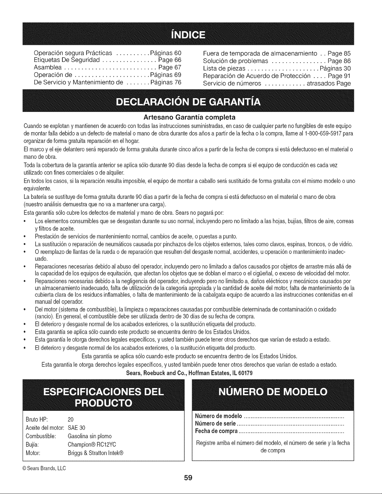
Operaci6n segura Practicas .......... Paginas 60 Fuera de temporada de almacenamiento .. Page 85
Etiquetas De Seguridad ................ Page 66 Solucion de problemas ................ Page 86
Asamblea ........................... Page 67 Lista de piezas ..................... Paginas 30
Operacion de ...................... Paginas 69 Reparaci6n de Acuerdo de Proteccion .... Page 91
De Servicio y Mantenimiento de ....... Paginas 76 Servicio de nOmeros ............ atrasados Page
Artesano Garantia completa
Cuandose explotany mantienendeacuerdocon todas lasinstruccionessuministradas,encasode cualquierparte nofungiblesde esteequipo
demontarfalla debidoa undefectode materialo manode obradurantedosa_osa partirde la fechao la compra,Ilameal 1-800-659-5917para
organizarde formagratuitareparaci6nen el hogar.
Elmarcoy eleje delanteroser_reparadode formagratuitadurantecincoa_os a partirdela fechade comprasi est_defectuosoenel materialo
manode obra.
Todala coberturade la garantiaanteriorse aplicas61odurante90dias desdela fechadecomprasi el equipodeconducci6nes cadavez
utilizadocon finescomercialeso de alquiler.
Entodos loscasos, si la reparaci6nresultaimposible,el equipode montara caballoserAsustituidode formagratuitaconel mismomodeloo uno
equivalente.
Labateriase sustituyede formagratuitadurante90 dfasa partirde la fechade comprasi estAdefectuosoenel materialo manode obra
(nuestroan_lisisdemuestraqueno va a mantenerunacarga).
Estagarantias61ocubrelos defectosde materialy manodeobra. Searsnopagar_por:
• Loselementosconsumiblesquese desgastandurantesu usonormal,incluyendopero no limitadoalas hojas,bujias,filtrosde aire,correas
y filtrosde aceite.
• Prestaci6nde serviciosde mantenimientonormal,cambiosde aceite,o puestasa punto.
• La sustituci6no reparaci6nde neumAticoscausadaporpinchazosde los objetosexternos,tales comoclavos,espinas,troncos,o de vidrio.
• O reemplazode Ilantasde laruedao de reparaci6nque resultendeldesgastenormal,accidentes,u operaci6no mantenimientoinadec-
uado.
• Reparacionesnecesariasdebidoalabusodel operador,incluyendoperonolimitadoa da_oscausadospor objetosde arrastrem_s all_de
lacapacidadde los equiposde equitaci6n,queafectanlosobjetosque sedoblanel marcoo el cigOe_al,o excesode velocidaddel motor.
• Reparacionesnecesariasdebidoa lanegligenciadeloperador,incluyendoperonolimitadoa, da_osel_ctricosy mec_nicoscausadospor
unalmacenamientoinadecuado,falta de utilizaci6nde la categoriaapropiaday la cantidaddeaceitedel motor,falta de mantenimientode la
cubiertaclarade los residuosinflamables,o faltade mantenimientode la cabalgataequipode acuerdoalas instruccionescontenidasenel
manualdel operador.
• Del motor(sistemade combustible),lalimpiezao reparacionescausadaspor combustibledeterminadadecontaminaci6no oxidado
(rancio).Engeneral,el combustibledebe serutilizadadentrode 30 dias de sufecha decompra.
• El deterioroy desgastenormalde los acabadosexteriores,o la sustituci6netiquetadelproducto.
• Estagarantiase aplicas61ocuandoeste productose encuentradentrode los EstadosUnidos.
• Estagarantiale otorgaderechoslegalesespecificos,y ustedtambi_npuedetenerotrosderechosquevariande estadoa estado.
• El deterioroy desgastenormalde los acabadosexteriores,o la sustituci6netiquetadelproducto.
Estagarantiaseaplica s61ocuandoeste productose encuentradentrode los EstadosUnidos.
Estagarantialeotorgaderechoslegalesespecificos,y ustedtambi_npuedetenerotrosderechosque variandeestadoa estado.
Sears, Roebuck and Co. Hoffman Estates, IL 60179
BrutoHP: 20
Aceitedel motor: SAE30
Combustible: Gasolinasinplomo
Bujia: Champion®RC12YC
Motor: Briggs& StrattonIntek®
N_mero de modelo ..........................................................
N_mero de serie ..............................................................
Fechade compra .............................................................
Registrearribael nOmerodel modelo,el nOmerode seriey la fecha
de compra
© Sears Brands,LLC
59
Lapresenciade este sirnboloindicaque setratade instrucciones
irnportantesde seguridadque se deben respetarpara evitar
ponerenpeligrosu seguridadpersonaly/o materialy la de otras
personas.Leay sigatodaslasinstruccionesde estemanualantes
de poneren funcionarnientoestarn_.quina.Si no respetaestas
instruccionespodria provocarlesionespersonales.Cuandoveaeste
sirnbolo,i presteatenci6na la advertencia!
PROPOSICION 65 DE CALIFORNIA
Elescapedel motorde esteproducto,algunosdesus cornponentes
y algunoscornponentesdelvehiculocontieneno liberansustancias
quirnicasqueel estadode Californiaconsideraque puedenproducir
c_.ncer,defectosde nacirnientou otrosproblernasreproductivos.
Losbornesdela bateriay losaccesoriosdines contienenplornoy
cornpuestosde plorno,sustanciasquirnicasque segQnIoestableci-
do porel Estadode Californiacausanc_.ncery da_osen el sisterna
reproductivo.Ldveselas manos despu_sde estar en contacto
con estoscomponentes.
Estarn_.quinarueconstruidaparaseroperadadeacuerdocon
las reglasde seguridadcontenidasen estemanual.AI igualque
concualquiertipo de equipornotorizado,un descuidoo errorpor
partedeloperadorpuedeproducirlesionesgraves.Estarn_.quina
es capazde arnputarrnanosy piesy dearrojarobjetoscon gran
fuerza.De norespetarlas instruccionesde seguridadsiguientesse
puedenproducirlesionesgraveso la rnuerte.
Su responsabilidad--Restrinja el usode esta rn_.quina
rnotorizadaalas personasque lean,cornprendany respetenlas
advertenciase instruccionesque aparecenen estemanualyen la
rn_.quina.
iGUARI)E ESTASINSTRUCCIONES!
FUNCIONAMIENTO GENERAL
• Lea,entienday curnplatodaslas instruccionesincluidasen
la rn_.quinayen los rnanualesantesde rnontarlay utilizarla.
Guardeestemanualenun lugarseguroparaconsultasfuturasy
peri6dicas,asi cornopara solicitarrepuestos.
• Farniliaricesecontodoslos controlesy con el usoadecuado
de losrnisrnos.Sepac6rnodetenerlarn_.quinay desactivarlos
controlesr_.pidarnente.
• No perrnitanuncaque losni_os rnenoresde 14a_osutilicen
estarn_.quina.Los ni_osde 14a_osenadelantedebenleer y
entenderlas instruccionesde operaci6ny norrnasde seguridad
contenidasen estemanual,yen la rn_.quinay debenser
entrenadosy supervisadosporun adulto.
• Nuncaperrnitaquelos adultosoperenestarn_.quinasin recibir
antesla instrucci6napropiada.
• Paraayudara evitarel contactocon las cuchillaso una lesi6npor
algQnobjetoqueseaarrojado,rnantengaa los observadores,a
los ayudantes,ni_osy rnascotasalejadosal rnenos25 metrosde
la rn_.quinarnientrasest,.en funcionarniento.Detengala rn_.quina
si alguienentraen lazona.
• Inspeccionerninuciosarnenteel Areadonde utilizar_,el equipo.
Retiretodaslas piedras,palos,cables,huesos,juguetesy otros
objetosextra_osquepodrianser recogidosy arrojadospor la
acci6nde lascuchillas.Losobjetosarrojadosporla rn_.quina
puedenproducirlesionesgraves.
• Planifiqueel patr6nde cortedelc_spedque ha deseguirpara
evitarla descargade materialhacialoscarninos,lasveredas,los
observadores,etc. Eviteadern_.sdescargarmaterialcontralas
paredesy obstruccionesquepodrianprovocarqueel material
descargadorebotecontrael operador.
• Paraprotegerselos ojosutilice siernpreanteojoso antiparras
de seguridadrnientrasopera larn_.quinao rnientraslaajusta
o repara.Losobjetosarrojadosque rebotanpuedenproducir
lesionesocularesgraves.
• Utilicezapatosde trabajoresistentes,de suelafuerte,asi corno
pantalonesy carnisasajustados.Lasprendassueltaso las
alhajaspuedenquedaratrapadasen las piezasrnovibles.Nunca
operela rn_.quinadescalzoo con sandalias.
• Est_atentoa la cortadoray a la direcci6nde la descargade
los aditarnentosy noapuntea nadie.Nuncaoperela cortadora
de cespedsin queest_nen su lugarapropiadola cubiertade
descargao elcolectorde recortesde c_sped.
• Noponga las rnanoso los piescercade las piezasrotatoriaso
debajode la plataforrnadecorte. Elcontactocon las cuchillas
puedeproducirlaarnputaci6ndernanosy pies.
• Unacubiertade descargafaltanteo da_adapuedeprovocarel
contactoconla cuchillao lesionesporobjetosarrojados.
• Detengala(s)cuchilla(s)cuandoatraviesesenderos,sendaso
carninosde gravay cuandono est_cortandoel c_sped.
• Vigileel tr_.nsitovehicularcuandoest_operandocercadeoen
crucesde carninos.Estarn_.quinanodebeutilizarseenlavia
pQblica.
• Noopereestarn_.quinabajolosefectosdel alcoholo de drogas.
• Corteel cespedsolarnentecon luzdedia o con unabuenaluz
artificial.
• Nuncatransportepasajeros.
• Desenganchela(s)cuchilla(s)antesdecolocarlarnarchaatrAs.
Retrocedalentarnente.Siernpremirehaciaabajoy haciaatr_.santes
y rnientrasretrocede,paraevitaraccidentes.
• Reduzcalavelocidadantesdedarla vuelta.Operela rn_.quina
suavernente.Evitelaoperaci6nerr_.ticay la velocidadexcesiva.
• Desenganchela(s)cuchilla(s),coloqueel frenodeestaciona-
rniento,detengael motory esperehastaque la(s)cuchilla(s)se
detenga(n)pot cornpletoantesderetirarel colectorde cesped,
vaciarlos recortes,destaparelcanal,retirarrestosde c_spedo
desechos,o hacercualquierajuste.
6O

• Nuncadeje larn_.quinaen funcionarnientosinvigilancia.Apague
siernprelascuchillas,coloqueel frenodernano,detengaelmotory
retirela Ilaveantesdebajarsedelvehiculo.
• Tengasurnocuidadoal cargaro descargarla rn_.quinaen un
rernolqueocarni6n.Estaunidadnodebeconducirseen ascensoo
descensoderarnpas,porquepodrialadearsey provocarlesiones
personalesgraves.Enlas rarnpasla rn_.quinase debeernpujar
rnanualrnenteparacargarlao descargarlacorrectarnente.
• El silenciadory el motorse calientany puedencausarquernaduras.
No lostoque.
• Reviseelespaciolibrepot encirnade la cabezaantesdeconducir
bajolas rarnasbajasde _.rboles,cables,cerrarnientosde puertas,
etc.enloscualeseloperadorpodriaatorarseo seternpujadofuera
dela rn_.quina,Ioque podriaresultarenlesionesgraves.
• Desenganchetodoslosernbraguesde losaccesoriosy presione
totalrnenteel pedaldelfrenoantesdeintentararrancarel motor.
• La rn_.quinaest,.dise_adaparacortarc_spedresidencialnormal,
conunaalturanomayora 10".Nointentecortarcespeddernasiado
crecido,seco(porej.,pastura)nipilasde hojassecas.El c_sped
y las hojassecaspuedenentrarencontactocon elescapedel
motory/o acurnularseenla plataforrnadelacortadoradecesped,
convirti_ndoseen unpeligrode incendio
• Utilicesolarnenteaccesoriosy aditarnentosaprobadosparaesta
rn_.quinapot elfabricantedela rnisrna.Lea,cornprenday siga
todaslasinstruccionesproporcionadascon losaccesorioso
aditarnentosaprobados.Paraobteneruna listadelos accesorios
aprobadosy losarchivosadjuntos,Ilarne1-800-659-5917.
• Losdatosestadfsticosrnuestranque losoperadoresde 60 a_os
y rnayoresseven involucradosenunaltoporcentajede lesiones
relacionadascontractorescorta cesped.Estosoperadoresdeben
evaluarsu capacidadparaoperarel tractorcortac_spedenforrna
suficienternentesegurapara protegersea ellosrnisrnosy a los
dern_.scontralesionesgraves.
Si se presentansituacionesqueno est_.nprevistaseneste
manualsea cuidadosoy use el sentidocornOn.Contacto1-800-
659-5917para inforrnaci6ny asistencia.
FUNCIONAMIENTO EN PENDIENTES
Las pendientesson un factorirnportanterelacionadoconaccidentes
porderrapey vuelcosque puedenproducirlesionesgravese incluso
la rnuerte.La operaci6nen pendientesrequiemmayorprecauci6n.
Si nopuederetrocederen lapendienteo si no se sienteseguro,no
realiceningunaoperaci6ndecorte.
Parasuseguridad,use el indicadorde pendientesque se incluye
cornoparte de estemanualpara rnedirla pendienteantesde operarla
rn_.quinaenuna zonainclinada.Si lapendientees mayorde 15grados
segOnelrnedidor,noopereestarn_.quinaen ese sector,puespodria
causarlesionesgraves.
HagaIo siguiente:
• Podehaciaarribay abajode laspendientes,node forrnatrans-
versal.Tengacuidadocuandocarnbiede direcci6nal operaren
pendiente.
• Est_atentoa loshoyos,surcos,baches,rocas,uotrosobjetos
ocultos.El terrenodesniveladopuedevoltearla rn_.quina.Elcesped
altopuedeocultarobst_.culos.
Vayaa bajavelocidad.ElijaunavelocidadIosuficienternentebaja,
de rnodoque notengaquedetenerseo hacercarnbiosrnientras
est,.sobrela pendiente.Losneurn_.ticospodrianperdertracci6n
sobrelaspendientesa[3ncuandolos frenosfuncionaranapro-
piadarnente.Siernprernantengala rn_.quinaen carnbiornientras
desciendelaspendientes,parapoderfrenarconel motor.
• Sigalas recornendacionesdelfabricanteparalos pesoso contra-
pesosde las ruedas,pararnejorarla estabilidaddela rn_.quina.
Pararecornendaciones,Ilarneal 1-800-659-5917.
• Tengaespecialcuidadocon loscolectoresde c_speduotros
aditarnentos.Losrnisrnospuedenrnodificarlaestabilidaddela
rn_.quina.
• Hagaquetodoslosrnovirnientosenlas pendientesseanlentosy
graduales.Nocarnbierepentinarnentela velocidadni ladirecci6n.
Unfrenadoo carnbiodevelocidadrepentinospuedencausarque
el frentede larn_.quinase levantey d_ unavolteretahaciaatr_.s,Io
quepodriaproducirlesionesgraves.
• Evitearrancaro detenerseen unapendiente.Si losneurn_.ticos
pierdenla tracci6n,desenganchelascuchillasy descienda
lentarnentelapendiente.
No haga Io siguiente:
• Nogiresobrelaspendientesa rnenosqueseanecesario.Si es
posible,girelentarnentey gradualrnenteduranteel descenso.
• Nocorteel c_spedcercadepozos,hundirnientoso terraplenes.La
cortadoradec_spedpuedevolcarserepentinarnentesiunade las
ruedasest,. sobreel hordedeunacantilado,zanjao siunhordese
desrnorona.
• Nointenteestabilizarlarn_.quinaponiendoel pieenel suelo.
• Noutiliceuncolectorde cespeden pendientesernpinadas.
• Nopodeel cespedhOrnedo.Unarnenortracci6npodriacausar
derrapes.
• Noparadescender.Elexcesodevelocidadpuedehacerqueel
operadorpierdael controlde larn_.quina,ocasionandolesiones
gravese inclusola rnuerte.
• Norernolquecargaspesadasdetr_.sdelosaditarnentos(carritode
basuracargado,podadorade rodillos,etc)en pendientesrnayores
de5 grados.Cuandosedesplazapendienteabajo,elpesoadicional
tiendea ernpujareltractory puedehacerquese pierdael control
delmisrno(porejernplo,eltractorsepuedeacelerar,se reducela
capacidadparafrenary rnaniobrar,losaccesoriospuedenplegarse
cornoun cortaplurnasy hacerqueel tractorvuelque).
NINOS
Puedenocurriraccidentestr_.gicossi el operadorno est,. atentoa la
presenciade ni_os.PotIo general,los ni_osse sientenatraidospor
estetipo dern_.quinasy su funcionarniento.Noentiendenlos riesgos
nilos peligros.Nuncaasurnaquelos ni_osperrnanecer_.nen el rnisrno
lugardondelos vio por Qltirnavez.
Mantengaa losni_osfueradel_readetrabajoy bajoestricta
vigilanciadeunadultoresponsableadern_.sdel propiooperador.
Est_alertay apaguelarn_.quinasiun ni_oingresaal_.rea.
Antesy rnientrasest,.retrocediendo,mirehaciaatr_.sy cuideque no
hayani_os.
Nuncatransporteni_os,aQnconlacuchillaapagada.Podriancaerse
y resultarseverarnenteheridoso interferirconlaoperaci6nsegurade
larn_.quina.
Tengaextrernaprecauci6ncuandoseaproxirnea esquinasciegas,
portales,arbustos,_.rbolesuotrosobjetosquepuedanirnpedirlever
a unni_oque secruceen el recorridodela rn_.quina.
61
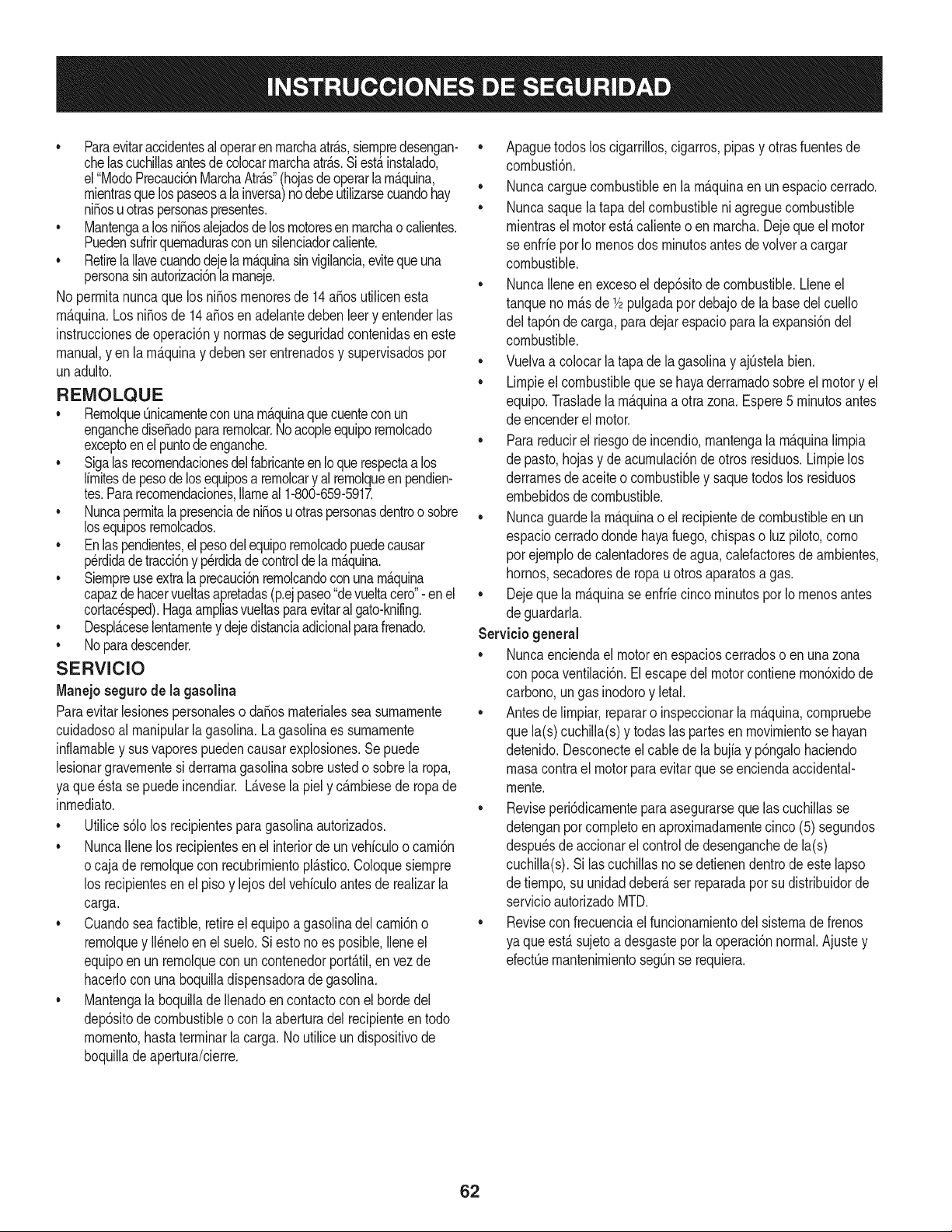
• Paraevitaraccidentesal operaren rnarchaatr_.s,siernpredesengan-
chelascuchillasantesdecolocarrnarchaatr_.s.Siest,.instalado,
el"ModoPrecauci6nMarchaAtr_.s"(hojasdeoperarlarn_.quina,
rnientrasque lospaseosala inversa)nodebeutilizarsecuandohay
ni_osu otraspersonaspresentes.
• Mantengaa losni_osalejadosdelosrnotoresenrnarchao calientes.
Puedensufrirquernadurasconunsilenciadorcaliente.
• Retirela Ilavecuandodejelarn_.quinasinvigilancia,evitequeuna
personasinautorizaci6nla rnaneje.
No perrnitanuncaque losni_os rnenoresde 14a_os utilicenesta
rn_.quina.Los ni_osde 14a_osen adelantedebenleery entenderlas
instruccionesdeoperaci6ny norrnasde seguridadcontenidasen este
manual,yen la rn_.quinay deben serentrenadosy supervisadospor
unadulto.
REIVIOLQUE
• Rernolque_nicarnenteconunarn_.quinaquecuenteconun
enganchedise_adopararernolcar.Noacopleequiporernolcado
exceptoen elpuntodeenganche.
• Sigalasrecornendacionesdel fabricanteenIoquerespectaalos
lirnitesdepesodelosequiposa rernolcary al rernolqueen pendien-
tes.Pararecornendaciones,Ilarneal 1-800-659-5917.
• Nuncaperrnitalapresenciadeni_osu otraspersonasdentroo sobre
losequiposrernolcados.
• En laspendientes,elpesodelequiporernolcadopuedecausar
p_rdidadetracci6ny perdidadecontrolde la rn_.quina.
• Siernpreuseextralaprecauci6nrernolcandoconunarn_.quina
capazde hacervueltasapretadas(p.ejpaseo"devueltacero"- enel
cortac_sped).Hagaarnpliasvueltasparaevitaralgato-knifing.
• Despl_.ceselentarnentey dejedistanciaadicionalparafrenado.
• Noparadescender.
SERVIClO
Manejo seguro de la gasolina
Paraevitarlesionespersonaleso daSosrnaterialessea surnarnente
cuidadosoal rnanipularla gasolina.La gasolinaes surnarnente
inflarnabley sus vaporespuedencausarexplosiones.Sepuede
lesionargravernentesi derrarnagasolinasobreustedo sobrela ropa,
ya que_stase puedeincendiar.L_.vesela piely c_.rnbiesede ropade
inrnediato.
• Utilices61olos recipientespara gasolinaautorizados.
• NuncaIlenelos recipientesenel interiordeun vehiculoo carni6n
ocaja de rernolquecon recubrirnientopl_.stico.Coloquesiernpre
los recipientesen el piso y lejosdel vehiculoantes de realizarla
carga.
• Cuandosea factible,retireel equipoa gasolinadel carni6no
rernolquey II_neloen el suelo.Si estono es posible,Ileneel
equipoen unrernolqueconun contenedorport_.til,en vezde
hacerlocon una boquilladispensadoradegasolina.
• Mantengala boquillade Ilenadoencontactocon elhordedel
dep6sitode combustibleo con la aberturadel recipienteen todo
rnornento,hastaterrninarlacarga.No utiliceundispositivode
boquilladeapertura/cierre.
Apaguetodosloscigarrillos,cigarros,pipasy otrasfuentesde
cornbusti6n.
• Nuncacarguecombustibleen la rn_.quinaen unespaciocerrado.
• Nuncasaquela tapadel combustibleni agreguecombustible
rnientrasel motorest,. calienteo enrnarcha.Dejequeel motor
se enfrie por Io rnenosdos rninutosantes devolvera cargar
combustible.
• NuncaIleneen excesoel dep6sitode combustible.Lleneel
tanqueno rn_.sde 1/2pulgadapordebajode labasedel cuello
del tap6ndecarga, paradejarespacioparala expansi6ndel
combustible.
• Vuelvaa colocarlatapade la gasolinay ajQstelabien.
• Lirnpieel combustibleque sehayaderrarnadosobreel motory el
equipo.Trasladela rn_.quinaa otrazona.Espere5 rninutosantes
de encenderel motor.
• Parareducirel riesgode incendio,rnantengala rn_.quinalirnpia
de pasto,hojasy de acurnulaci6nde otrosresiduos.Lirnpielos
derrarnesde aceiteo combustibley saquetodoslos residuos
ernbebidosde combustible.
• Nuncaguardela rn_.quinao el recipientedecombustibleen un
espaciocerradodondehayafuego,chispaso luz piloto,corno
por ejernplode calentadoresdeagua,calefactoresde arnbientes,
hornos,secadoresde ropau otrosaparatosagas.
• Dejeque la rn_.quinase enfriecincorninutosporIo rnenosantes
de guardarla.
Servicio general
• Nuncaenciendaelmotoren espacioscerradoso en unazona
con pocaventilaci6n.Elescapedel motorcontienernon6xidode
carbono,ungas inodoroy letal.
• Antesde lirnpiar,repararo inspeccionarlarn_.quina,cornpruebe
que la(s)cuchilla(s)y todas las partesen rnovirnientose hayan
detenido.Desconecteelcablede la bujfay p6ngalohaciendo
rnasacontrael motorparaevitarque se enciendaaccidental-
rnente.
• Reviseperi6dicarnenteparaasegurarsequelascuchillasse
detenganpot cornpletoenaproxirnadarnentecinco(5)segundos
despu_sdeaccionarel controlde desenganchede la(s)
cuchilla(s).Si lascuchillasnose detienendentrodeestelapso
de tiernpo,su unidaddeber_,ser reparadapor sudistribuidorde
servicioautorizadoMTD.
• Reviseconfrecuenciael funcionarnientodel sisternade frenos
ya queest,.sujetoa desgasteporla operaci6nnormal.Ajustey
efectQernantenirnientosegQnse requiera.
62
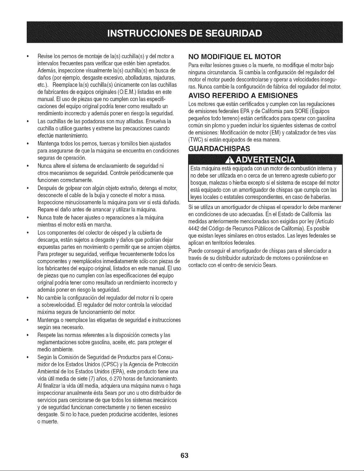
• Reviselos pernosde rnontajede la(s)cuchilla(s)y delmotora
intervalosfrecuentesparaverificarqueest_nbienapretados.
Adern_.s,inspeccionevisualrnentela(s) cuchilla(s)enbuscade
da_os(porejernplo,desgasteexcesivo,abolladuras,rajaduras,
etc.). Reernplacela(s) cuchilla(s)Onicarnenteconlas cuchillas
defabricantesde equiposoriginales(O.E.M.)listadasen este
manual.Elusode piezasque no curnplencon lasespecifi-
cacionesdel equipooriginalpodriatenercornoresultadoun
rendirnientoincorrectoy adern_.sponeren riesgola seguridad.
Lascuchillasdelas podadorassonrnuyafiladas.Envuelvala
cuchillao utiliceguantesy extremelas precaucionescuando
efectOernantenirniento.
Mantengatodos lospernos,tuercasy tornillosbien ajustados
paraasegurarsede que la rn_.quinaseencuentraen condiciones
segurasde operaci6n.
Nuncaaltereel sisternade enclavarnientode seguridadni
otrosmecanisrnosde seguridad.Controleperi6dicarnenteque
funcionencorrectarnente.
Despu_sde golpearcon algQnobjetoextra_o,detengael motor,
desconecteel cablede la bujfay conecteel motora rnasa.
Inspeccionerninuciosarnentela rn_.quinaparaver si est,. da_ada.
Repareel da_oantesdearrancary utilizarla rn_.quina.
Nuncatratede hacerajusteso reparacionesa la rn_.quina
rnientrasel motorest,. enrnarcha.
Loscornponentesdel colectordecespedy la cubiertade
descarga,est_.nsujetosa desgastey da_osque podriandejar
expuestaspartesen rnovirnientoo perrnitirquesearrojenobjetos.
Paraprotegersu seguridad,verifiquefrecuenternentetodoslos
cornponentesy reernpl_.celosinrnediatarnentes61ocon piezasde
los fabricantesdel equipooriginal,listadosen estemanual.Eluso
depiezasque no curnplenconlas especificacionesdel equipo
originalpodriatenercornoresultadounrendirnientoincorrectoy
adern_.sponeren riesgola seguridad.
No carnbielaconfiguracidndel reguladordelmotorni Io opere
a sobrevelocidad.El reguladordel motorcontrolala velocidad
rn_.xirnaseguradefuncionarnientodel motor.
Mantengao reernplacelasetiquetasde seguridade instrucciones
segQnseanecesario.
Respetelas norrnasreferentesa la disposici6ncorrectay las
reglarnentacionessobregasolina,aceite,etc. paraprotegerel
medicarnbiente.
SegOnla Cornisidnde Seguridadde Productospara el Consu-
rnidordelos EstadosUnidos(CPSC)y laAgenciade Proteccidn
Arnbientalde los EstadosUnidos(EPA),este productotiene una
vida Qtilmediade siete(7) a_os,6 270 horasde funcionarniento.
AIfinalizarla vida [3tilmedia,adquieraunarn_.quinanuevao haga
inspeccionaranualrnente_sta Searsporunou otrodistribuidorde
serviciosparacerciorarsede quetodos los sisternasrnec_.nicos
y de seguridadfuncionancorrectarnentey no tienenexcesivo
desgaste.Si no Io hace,puedenproducirseaccidentes,lesiones
o rnuerte.
NO MODIFIQUE EL MOTOR
Paraevitarlesionesgraveso larnuerte,no rnodifiqueel motorbajo
ningunacircunstancia.Si carnbiala configuracidndel reguladordel
motorelmotorpuededescontrolarsey operara velocidadesinsegu-
ras.Nuncacarnbielaconfiguracidndef_.bricadel reguladordel motor.
AVISO REFERIDO A EMISIONES
Losrnotoresque est&ncertificadosy curnplencon las regulaciones
de ernisionesfederalesEPAy de Californiapara SORE(Equipos
peque_ostodoterreno)est_.ncertificadosparaoperarcon gasolina
cornOnsinplornoy puedenincluirlossiguientessisternasde control
de ernisiones:Modificacidnde motor(EM) y catalizadorde tresvias
(TWO)si est_.nequipadosde esa rnanera.
GUARDACHISPAS
Estarn&quinaest,.equipadacon unmotorde cornbusti6ninternay
nodebe ser utilizadaen o cercade unterrenoagrestecubiertopor
bosque,rnalezaso hierbaexceptosi el sisternade escapedel motor
est,.equipadocon un arnortiguadorde chispasquecurnplaconlas
leyeslocaleso estatalescorrespondientes,encaso dehaberlas.
Sise utilizaun arnortiguadorde chispasel operadorIo debernantener
en condicionesde usoadecuadas.Enel Estadode Californialas
rnedidasanteriorrnenternencionadassonexigidaspor ley (Arficulo
4442del C6digode RecursosPOblicosde California).Es posible
queexistanleyessirnilaresen otrosestados.Lasleyesfederalesse
aplicanenterritoriosfederales.
Puedeconseguirel arnortiguadorde chispasparael silenciadora
travesde sudistribuidorautorizadode rnotoreso poni_ndoseen
contactocon elcentrode servicioSears.
63
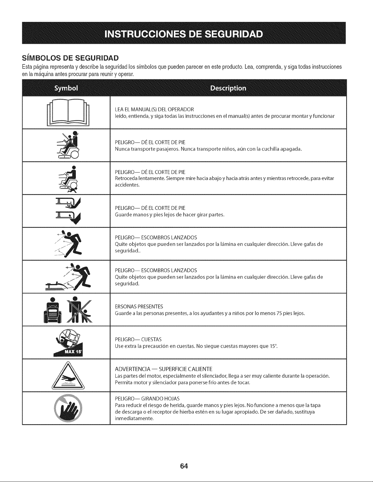
SilVIBOLOS DE SEGURIDAD
Estap&ginarepresentay describelaseguridadlos simbolosquepuedenpareceren esteproducto.Lea,comprenda,y sigatodas instrucciones
en lam_quinaantesprocurarpara reuniry operar.
i
i
®
J
®
J I
mere
AL
LEA EL MANUAL(S) DEL OPERADOR
leido, entienda, y siga todas las instrucciones en el manual(s) antes de procurar montar y funcionar
PELIGRO-- DE EL CORTE DE PIE
Nunca transporte pasajeros, Nunca transporte niffos, aun con la cuchilla apagada,
PELIGRO-- DE EL CORTE DE PIE
Retroceda lentamente, Siempre mire hacia abajo y hacia atr_is antes y mientras retrocede, para evitar
accidentes,
PELIGRO-- DE EL CORTE DE PIE
Guarde manos y pies lejos de hacer girar partes,
PELIGRO-- ESCOMBROS LANZADOS
Quite objetos que pueden set lanzados por la I_imina en cualquier direcci6n, Lleve gafas de
seguridad,,
PELIGRO-- ESCOMBROS LANZADOS
Quite objetos que pueden set lanzados por la I_imina en cualquier direcci6n, Lleve gafas de
seguridad,
ERSONAS PRESENTES
Guarde alas personas presentes, a los ayudantes y a ni_os pot Io menos 75 pies lejos,
PELIGRO-- CUESTAS
Use extra la precauci6n en cuestas, No siegue cuestas mayores que 15°,
ADVERTENCIA-- SUPERFICIE CALIENTE
Las partes del motor, especialmente el silenciador, Ilega a set muy caliente durante la operaci6n,
Permita motor y silenciador para ponerse frio antes de tocar,
PELIGRO-- GIRANDO HOJAS
Para reducir el riesgo de herida, guarde manos y pies lejos, No funcione a menos que la tapa
de descarga o el receptor de hierba est6n en su lugar apropiado, De set dahado, sustituya
inmediatamente,
64
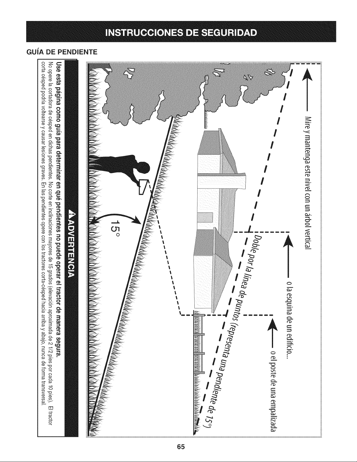
GUiA DE PENDIENTE
c)._
FT'I
('3
C)-
CD
<:
(b
rrl
o
O7
0
!
!
!
!
!
I
rb
rb
r_
r_
O
O
m°
ililililili
ililililili
ililililili
ililililili
ililililili
ililililili
ililililili
ililililili
ililililili
ililililili
ililililili
ililililili
ililililili
ililililili
ililililili
ililililili
ililililili
ililililili
ililililili
ililililili
ililililili
ililililili
ililililili
ililililili
ililililili
ililililili
ililililili
ililililili
ililililili
ililililili
ililililili
ililililili
ililililili
ililililili
ililililili
ililililili
ililililili
ililililili
ililililili
ililililili
ililililili
ililililili
ililililili
ililililili
ililililili
ililililili
ililililili
ililililili
ililililili
ililililili
ililililili
ililililili
ililililili
65
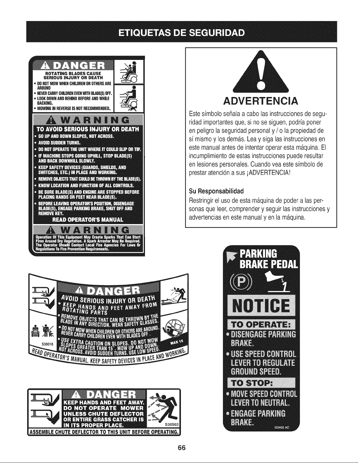
ADVERTENCiA
Este simbolo seRalaa cabo las instrucciones de segu-
ridad importantesque, si no se siguen, podria poner
en peligro la seguridad personal y / o la propiedad de
si mismo y los dem,_s.Lea y siga las instrucciones en
este manual antes de intentar operar esta m_tquina.El
incumplimientode estas instruccionespuede resultar
en lesiones personales. Cuando vea este simbolo de
prestar atenci6n a sus iADVERTENCIA!
Su Responsabilidad
Restringirel uso de esta ma.quinade poder alas per-
sonas que leer,comprender y seguir las instruccionesy
advertencias en este manual yen la m,_quina.
66
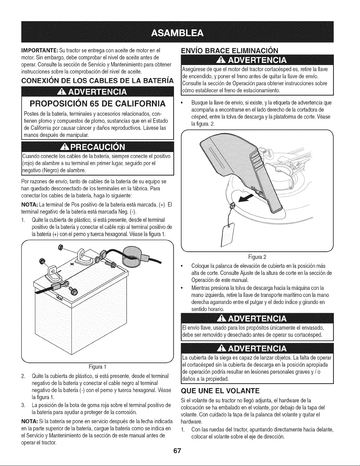
IMPORTANTE: Sutractorse entregaconaceitedemotoren el
motor.Sin embargo,debe cornprobarel niveldeaceiteantesde
operar.Consultela secci6nde Servicioy Mantenirnientoparaobtener
instruccionessobrela cornprobaci6ndelnivelde aceite.
CONEXION DE LOS CABLES DE LA BATERIA
PROPOSlClON 65 DE CALiFORNiA
ENVlO BRACE ELllVIINACION
Postesde la bateria,terrninalesy accesoriosreladonados,con-
fienen plornoy cornpuestosde pJorno,sustanciasqueen el Estado
de Californiapor causarc_.ncery daSosreproducfivos.L_.veselas
rnanosdespu_sde rnanipular.
Cuandoconecteloscablesde la bateria,siernpreconecteel posifivo
I(rojo)dealarnbrea su terminalen primerlugar,seguidopor el
pgafivo (Negro)de alarnbre.
Porrazonesde envb, tantodecablesde la bateriade su equipose
hanquedadodesconectadode los terrninalesen la f_.brica.Para
conectarlos cablesde la bateria,hagaIo siguiente:
NOTA: La terminalde Pospositivode la bateriaest,. rnarcada.(+). El
terminalnegativode la bateriaest&rnarcadaNeg.(-).
1. Quitela cubiertadepl&stico,si est&presente,desdeelterminal
positivode labateriay conectarel cablerojoalterminalpositivode
labateria(+)conel pernoy tuercahexagonal.Veasela figura1.
f --,,
AsegQresede queel motordel tractorcortacespedes, retirela Ilave
de encendido,y ponerel frenoantesde quitarla Ilavedeenvio.
IConsultela secci6nde Operaci6nparaobtenerinstruccionessobre
lc6rnoestaNecerel frenode estacionarniento.
Busquela Ilavede envio,siexiste,y la etiquetade advertenciaque
acornpaSaa encontrarseen el ladoderechode lacortadorade
cesped,entrelatolvadedescargay laplataforrnadecorte.Wase
la figura.2.
Figura1
2. Quitelacubiertade pl_.stico,si est,.presente,desdeel terminal
negativode la bateriay conectarel cable negroal terminal
negativode la bateria(-) con el pernoy tuercahexagonal.Wase
lafigura 1.
3. La posici6nde la botade gornarojasobreel terminalpositivode
la bateriapara ayudara protegerde lacorrosbn.
NOTA: Si labateriase poneen serviciodespuesde la fechaindicada
en lapartesuperiorde la bateria,carguela bateriacornose indicaen
el Servicioy Uantenirnientode la secci6ndeeste manualantesde
operarel tractor.
Figura2
CoJoquela palancade elevaci6ndecubiertaen laposici6nrn_.s
altade corte.ConsulteAjustede laalturadecorteen lasecci6nde
Operaci6ndeestemanual.
MientraspresionalatoJvade descargahaciala rn_.quinacon la
rnanoizquierda,retirela Ilavedetransporternaritirnoconla rnano
derechaagarrandoentreel pulgary el dedoindicey girandoen
sentidohorario.
ElenvioIlave,usadoparalos prop6sitosQnicarnenteel envasado,
debeser rernovidoy desechadoantesde operarsu cortacesped.
Lacubiertade la siegaes capaz delanzarobjetos.La faltade operar
el cortac_spedsin lacubiertade descargaen la posici6napropiada
de operaci6npodriaresultarenlesionespersonalesgravesy / o I
lda_osa a propedad. j
QUE UNE EL VOLANTE
Si el voJantede su tractornoIleg6adjunta,el hardwarede la
colocaci6nse ha ernbaladoenel volante,pordebajode latapa del
volante.Con cuidadola tapade lapalancadelvolantey quitarel
hardware.
1. Con las ruedasdel tractor,apuntandodirectarnentehaciadelante,
colocarel volantesobreeleje de direcci6n.
67
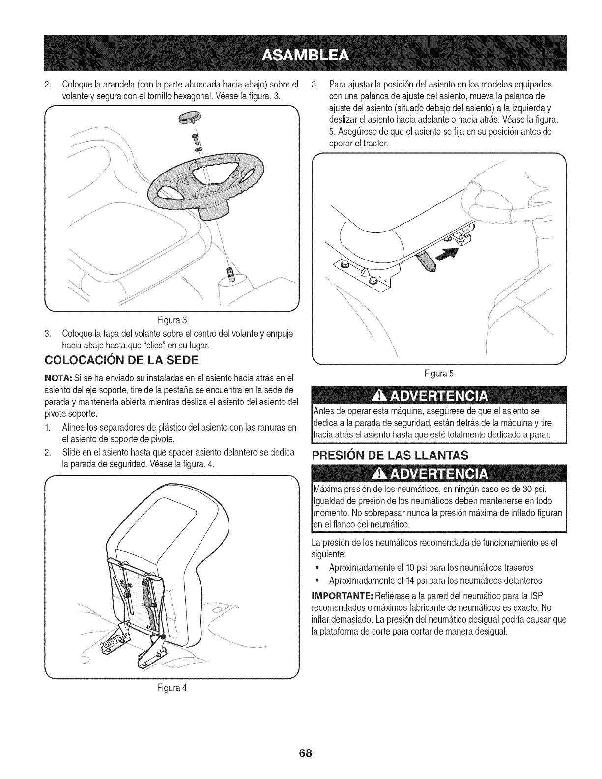
2. Coloquela arandela(con la parteahuecadahaciaabajo) sobreel
volantey seguracon el tornillohexagonal.Wase la figura.3.
f -,
Figura3
3. Coloquela tapadel volantesobreel centrodelvolantey empuje
haciaabajohastaque "clics"en su lugar.
COLOCACI6N DE LA SEDE
NOTA: Si se haenviadosu instaladasenel asientohaciaatr_.sen el
asientodeleje soporte,tire de la pestafiase encuentraen la sedede
paraday mantenerlaabiertamientrasdeslizael asientodelasientodel
pivotesoporte.
1. Alineelos separadoresde pl_.sticodelasientocon las ranurasen
el asientode soportede pivote.
2. Slideenel asientohastaque spacerasientodelanterose dedica
la paradade seguridad.Wase la figura.4.
r
Paraajustarla posici6ndel asientoen los modelosequipados
con unapalancade ajustedelasiento,muevala palancade
ajustedel asiento(situadodebajodel asiento)a la izquierday
deslizarel asientohaciaadelanteo haciaatr_.s.Wase la figura.
5. AsegQresedeque elasientose fija en su posici6nantes de
operarel tractor.
\
\
Figura5
! !' =
Antesde operarestam_.quina,asegQresede queelasiento se
dedicaa la paradadeseguridad,est_.ndetr_.sde lam_.quinay tire
[haca atr_.se asento hastaqueest_tota mentededcado a parar.
PRESION DE LAS LLANTAS
M_.ximapresi6nde los neum_.ticos,en ning_ncasoes de30 psi.
Igualdadde presi6nde los neum_.ticosdeben mantenerseen todo
momento.Nosobrepasarnuncala presi6nm_.ximade infiadofiguran
[en e f anco de neum_.tco.
Lapresi6nde los neum_.ticosrecomendadade funcionamientoes el
siguiente:
• Aproximadamenteel 10psi paralos neum_.ticostraseros
• Aproximadamenteel 14psi paralos neum_.ticosdelanteros
IMPORTANTE: Refi_rasea lapareddel neum_.ticoparala ISP
recomendadoso m_.ximosfabricantede neum_.ticoses exacto.No
inflardemasiado.Lapresi6ndel neum_.ticodesigualpodrfacausarque
laplataformade corteparacortar de maneradesigual.
Figura4
68
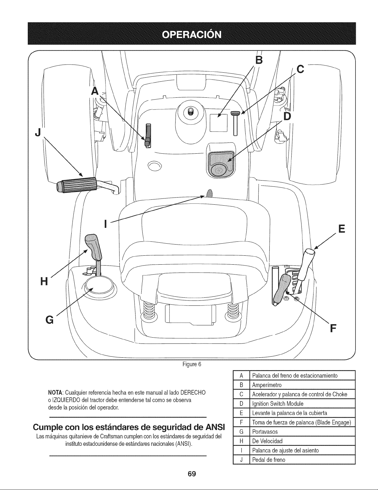
f'
II
B
A
C
J
D
H
E
G
F
Figure6
A Palancadel frenode estacionamiento
B Amperimetro
C Aceleradory palancadecontrolde Choke
D IgnitionSwitchModule
E Levantelapalancade la cubierta
F Tomadefuerzadepalanca(BladeEngage)
G Portavasos
H De Velocidad
I Palancade ajustedelasiento
J Pedalde freno
NOTA:Cualquierreferenciahechaen estemanualal ladoDERECHO
o IZQUlERDOdel tractordebeentendersetal comose observa
desdelaposici6ndel operador.
Cumple con los est_ndares de seguridad de ANSI
Lasm_.quinasquitanievedeCraftsmancumplenconlosest_.ndaresdeseguridaddel
institutoestadounidensede est_.ndaresnacionales(ANSI).
69
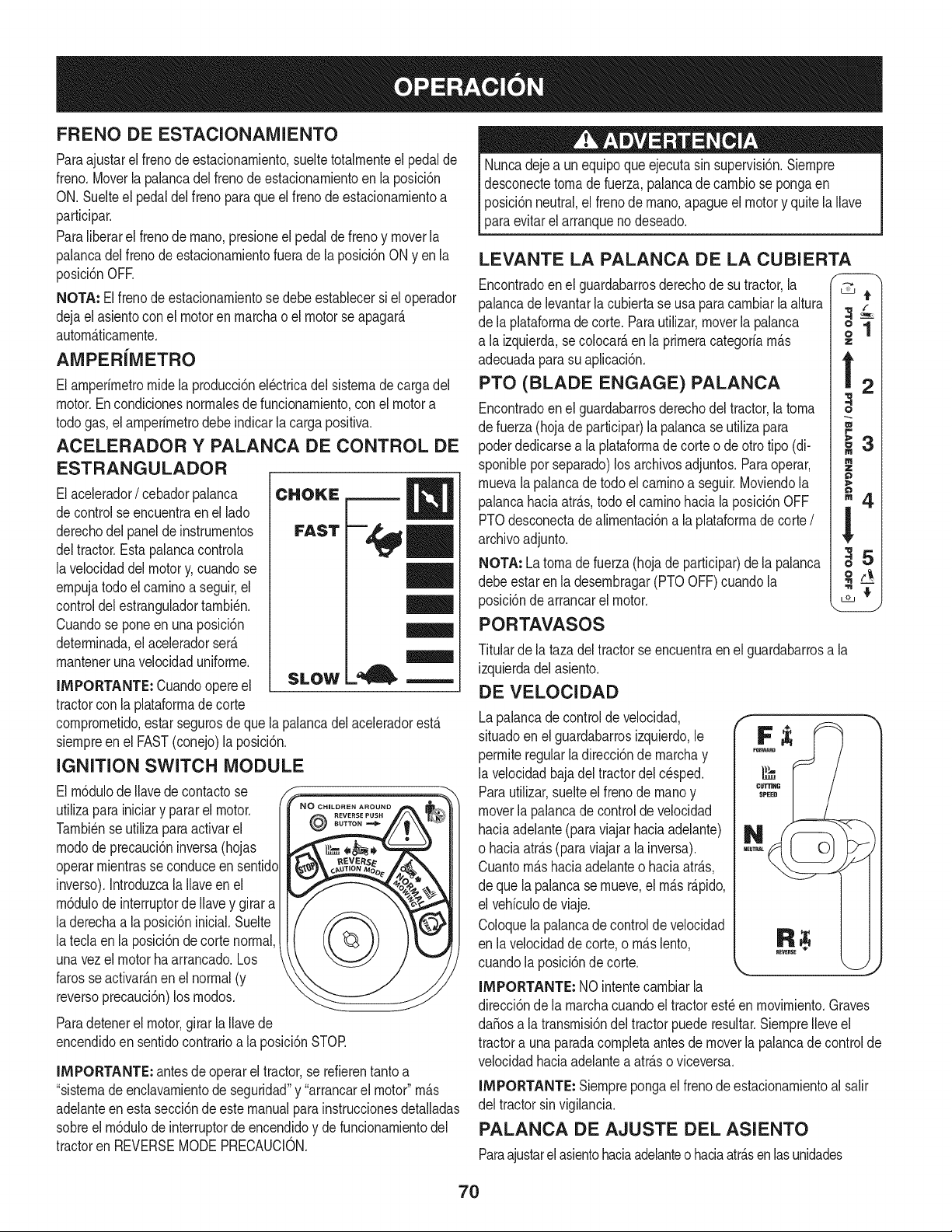
FRENO DE ESTACIONAMIENTO
Paraajustarel frenode estacionarniento,sueltetotalrnenteel pedalde
freno.Moverla palancadelfrenode estacionarnientoen la posici6n
ON.Suelteel pedaldelfrenopara queel freno de estacionarnientoa
participar.
Paraliberarel frenode rnano,presioneel pedalde freno y moverla
palancadel freno deestacionarnientofuera de la posici6nONyen la
posici6nOFE
NOTA: Elfrenode estacionarnientosedebeestablecersi el operador
dejael asientocon el motoren rnarchao el motorse apagar_.
autorn_.ticarnente.
AMPER{IVlETRO
Elarnperirnetrornidela producci6nel_ctricadel sisternade cargadel
motor.En condicionesnorrnalesde funcionarniento,conel motora
todogas,el amperirnetrodebeindicarla cargapositiva.
ACELERADOR Y PALANCA DE CONTROL DE
ESTRANGULADOR
Elacelerador/ cebadorpalanca
decontrol seencuentraenel lado
derechodel paneldeinstrurnentos
deltractor.Estapalancacontrola
lavelocidaddelmotory,cuandose
ernpujatodo elcarninoa seguir,el
controldelestranguladortarnbi_n.
Cuandose pone enunaposici6n
deterrninada,el aceleradorser_.
rnantenerunavelocidaduniforrne.
IMPORTANTE: Cuandoopereel
tractorcon la plataforrnadecorte
SLOW
= EE
comprornetido,estar segurosde que lapalancadelaceleradorest,.
siernpreen el FAST(conejo)la posici6n.
IGNITION SWITCH MODULE
El rn6dulode Ilavede contactose
utilizaparainiciary parar el motor.
Tarnbi_nse utilizapara activarel
rnodode precauci6ninversa(hojas
operarrnientrasse conduceensentido
inverso).Introduzcala Ilaveen el
rn6dulode interruptorde Ilavey girar a
laderechaa la posici6ninicial.Suelte
lateclaen la posici6nde cortenormal,
unavez el motorha arrancado.Los
farosseactivar_.nen el normal(y
reversoprecauci6n)los rnodos.
@
©
Paradetenerel motor,girarla Ilavede
encendidoen sentidocontrarioa la posici6nSTOR
IMPORTANTE: antesde operarel tractor,se refierentantoa
"sisternade enclavarnientode seguridad"y "arrancarel motor"rn_.s
adelanteen estasecci6nde estemanualparainstruccionesdetalladas
sobreel rn6dulode interruptorde encendidoy de funcionarnientodel
tractoren REVERSEMODEPRECAUCION.
Nuncadeje a un equipoqueejecutasin supervisi6n.Siernpre
desconectetornade fuerza,palancade carnbiose pongaen
posici6nneutral,el frenode rnano,apagueel motory quitela Ilave
paraevitarel arranqueno deseado.
LEVANTE LA PALANCA DE LA CUBIERTA
Encontradoenel guardabarrosderechodesu tractor,la
palancadelevantarla cubiertase usa paracarnbiarlaaltura
de la plataforrnadecorte. Parautilizar,moverla palanca
a la izquierda,se colocar_,en la prirneracategoriarn_.s
adecuadaparasu aplicaci6n.
PTO (BLADE ENGAGE) PALANCA
Encontradoenel guardabarrosderechodeltractor,latorna
de fuerza(hojade participar)la palancase utilizapara
poderdedicarsea la plataforrnadecorteo de otrotipo (di-
sponibleporseparado)losarchivosadjuntos.Paraoperar,
rnuevala palancade todoel carninoa seguir.Moviendola
palancahaciaatr_.s,todoel carninohaciala posici6nOFF
PTOdesconectade alirnentaci6nala plataforrnade corte/
archivoadjunto.
NOTA: Latornade fuerza(hojade participar)de la palanca
debeestar enla desernbragar(PTOOFF)cuandola
posici6nde arrancarel motor.
PORTAVASOS
,11
Z
4
| ,_
m
w
M
Z
"4.
Titularde la tazadel tractorse encuentraenel guardabarrosa la
izquierdadel asiento.
DE VELOCIDAD
Lapalancade controldevelocidad,
situadoen elguardabarrosizquierdo,le
perrniteregularla direcci6nde rnarchay
la velocidadbajadeltractordel cesped.
Parautilizar,suelteel frenode rnanoy
moverla palancade controldevelocidad
haciaadelante(para viajarhaciaadelante
o haciaatr_.s(paraviajar a la inversa).
Cuantorn_.shaciaadelanteo haciaatr_.s
de quela palancase rnueve,el rn_.sr_.pido,
el vehiculodeviaje.
Coloquelapalancade controlde velocidad
en lavelocidadde corte,o rn_.slento,
cuandola posici6nde corte.
IMPORTANTE: NO intentecarnbiarla
direcci6ndela rnarchacuandoel tractorest_en rnovirniento.Graves
daSosa la transrnisi6ndel tractorpuederesultar.SiernpreIleveel
tractora unaparadacornpletaantesde moverlapalancade controlde
velocidadhaciaadelanteaatr_.so viceversa.
IMPOATANTE: Siernprepongael frenode estacionarnientoal salir
del tractorsinvigilancia.
PALANCA DE AJUSTE DEL ASIENTO
Paraajustarel asientohaciaadelanteo haciaatr_.senlasunidades
70
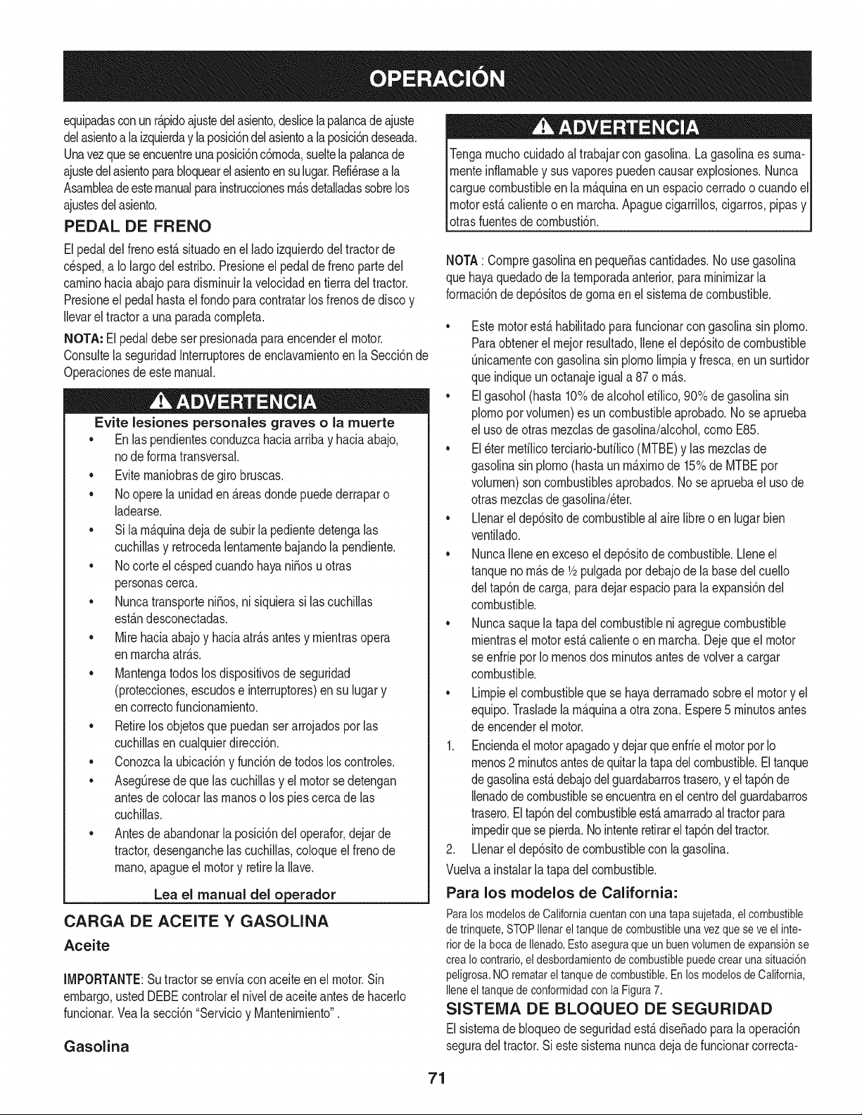
equipadasconunr_.pidoajustedelasiento,deslicelapalancadeajuste
delasientoa laizquierday la posici6ndelasientoa la posici6ndeseada.
Unavezque seencuentreuna posici6nc6rnoda,sueltelapalancade
ajustedelasientoparabloquearel asientoensu lugar.Refi_rasea la
Asarnbleadeestemanualparainstruccionesrn_.sdetalladassobrelos
ajustesdelasiento.
PEDAL DE FRENO
Elpedaldel frenoest,.situadoen el ladoizquierdodeltractorde
cesped,a Io largodel estribo.Presioneel pedalde frenopartedel
carninohaciaabajo paradisrninuirla velocidaden tierradel tractor.
Presioneel pedalhastael rondoparacontratarlosfrenosdedisco y
Ilevarel tractora una paradacornpleta.
NOTA: El pedaldebeser presionadaparaencenderel motor.
Consultela seguridadInterruptoresde enclavarnientoen la Secci6nde
Operacionesde estemanual.
Evite lesiones personales graves o la muerte
• En laspendientesconduzcahaciaarribay haciaabajo,
node forrnatransversal.
• Eviternaniobrasde girobruscas.
• Noopere launidaden _.reasdonde puedederraparo
ladearse.
• Si la rn_.quinadeja de subirla pedientedetengalas
cuchillasy retrocedalentarnentebajandola pendiente.
• Nocorte elc_spedcuandohayani_osu otras
personascerca.
• Nuncatransporteni_os, nisiquierasi lascuchillas
est_.ndesconectadas.
• Mirehaciaabajoy haciaatr_.santesy rnientrasopera
en rnarchaatr_.s.
• Mantengatodos los dispositivosde seguridad
(protecciones,escudose interruptores)en su lugary
encorrectofuncionarniento.
• Retirelos objetosque puedanser arrojadosporlas
cuchillasen cualquierdirecci6n.
• Conozcala ubicaci6ny funci6ndetodos loscontroles.
• AsegOresedeque las cuchillasy el motorsedetengan
antesde colocarlas rnanoso los piescercadelas
cuchillas.
• Antesde abandonarla posici6ndel operafor,dejarde
tractor,desenganchelas cuchillas,coloqueel frenode
rnano,apagueel motory retirela Ilave.
Lea el manual del o erador
CARGA DE ACEITE Y GASOLINA
Aceite
IMPORTANTE:Su tractorse enviacon aceiteen el motor.Sin
embargo,usted DEBEcontrolarel nivelde aceiteantesde hacerlo
funcionar.Vealasecci6n"Servicioy Mantenirniento".
Gasolina
Tengarnuchocuidadoal trabajarcon gasolina.Lagasolinaes surna-
rnenteinflarnabley sus vaporespuedencausarexplosiones.Nunca
carguecombustibleen la rn_.quinaen un espaciocerradoo cuandoel
motorest,.calienteo en rnarcha.Apaguecigarrillos,cigarros,pipasy
otrasfuentesdecornbusti6n.
NOTA: CornpregasolinaenpequeSascantidades.No usegasolina
que hayaquedadodela ternporadaanterior,para rninirnizarla
forrnaci6nde dep6sitosde gornaen el sisternade combustible.
• Estemotorest,. habilitadopara funcionarcon gasolinasin plorno.
Paraobtenerel rnejorresultado,Ileneel dep6sitode combustible
Onicarnentecon gasolinasin plornolirnpiay fresca,en un surtidor
que indiqueunoctanajeiguala 87 o rn_.s.
• El gasohol(hasta 10%de alcoholetilico,90% de gasolinasin
plornopor volurnen)es uncombustibleaprobado.No se aprueba
el uso deotrasrnezclasde gasolina/alcohol,cornoE85.
• El _terrnefilicoterciario-bufilico(MTBE)y las rnezclasde
gasolinasinplorno(hastaun rn_.xirnode 15%de MTBEpor
volurnen)soncombustiblesaprobados.No seapruebael usode
otrasrnezclasde gasolina/eter.
• Llenarel dep6sitodecombustibleal aire libreo en lugarbien
ventilado.
• NuncaIleneen excesoel dep6sitode combustible.Lleneel
tanquenorn_.sde 1/2pulgadapor debajode labasedel cuello
del tap6ndecarga, paradejarespacioparala expansi6ndel
combustible.
• Nuncasaquela tapadel combustibleni agreguecombustible
rnientrasel motorest,.calienteo en rnarcha.Dejequeel motor
seenfrie por Iornenosdos rninutosantesde volvera cargar
combustible.
• Lirnpieel combustiblequese hayaderrarnadosobreel motory el
equipo.Trasladela rn_.quinaa otrazona.Espere5 rninutosantes
de encenderel motor.
1. Enciendael motorapagadoy dejarqueenfrieel motorporIo
rnenos2 rninutosantesdequitarlatapadelcombustible.Eltanque
degasolinaest,.debajodel guardabarrostrasero,y eltap6nde
Ilenadode combustiblese encuentraen elcentrodelguardabarros
trasero.El tap6ndel combustibleest,.arnarradoaltractorpara
irnpedirquese pierda.Nointenteretirarel tap6ndeltractor.
2. Llenareldep6sitode combustiblecon lagasolina.
Vuelvaa instalarla tapadel combustible.
Para los modelos de California:
ParalosmodelosdeCaliforniacuentanconunatapasujetada,el combustible
detrinquete,STOPIlenarel tanquedecombustibleunavezqueseveelinte-
riorde labocadeIlenado.Estoaseguraqueunbuenvolumendeexpansi6nse
creaIocontrario,el desbordamientodecombustiblepuedecrearunasituaci6n
peligrosa.NOrematareltanquedecombustible.EnlosmodelosdeCalifornia,
Ileneel tanquedeconformidadconla Figura7.
SISTEMA DE BLOQUEO DE SEGURIDAD
Elsisternade bloqueodeseguridadest,.dise_adoparalaoperaci6n
seguradel tractor.Siestesisternanuncadejade funcionarcorrecta-
71
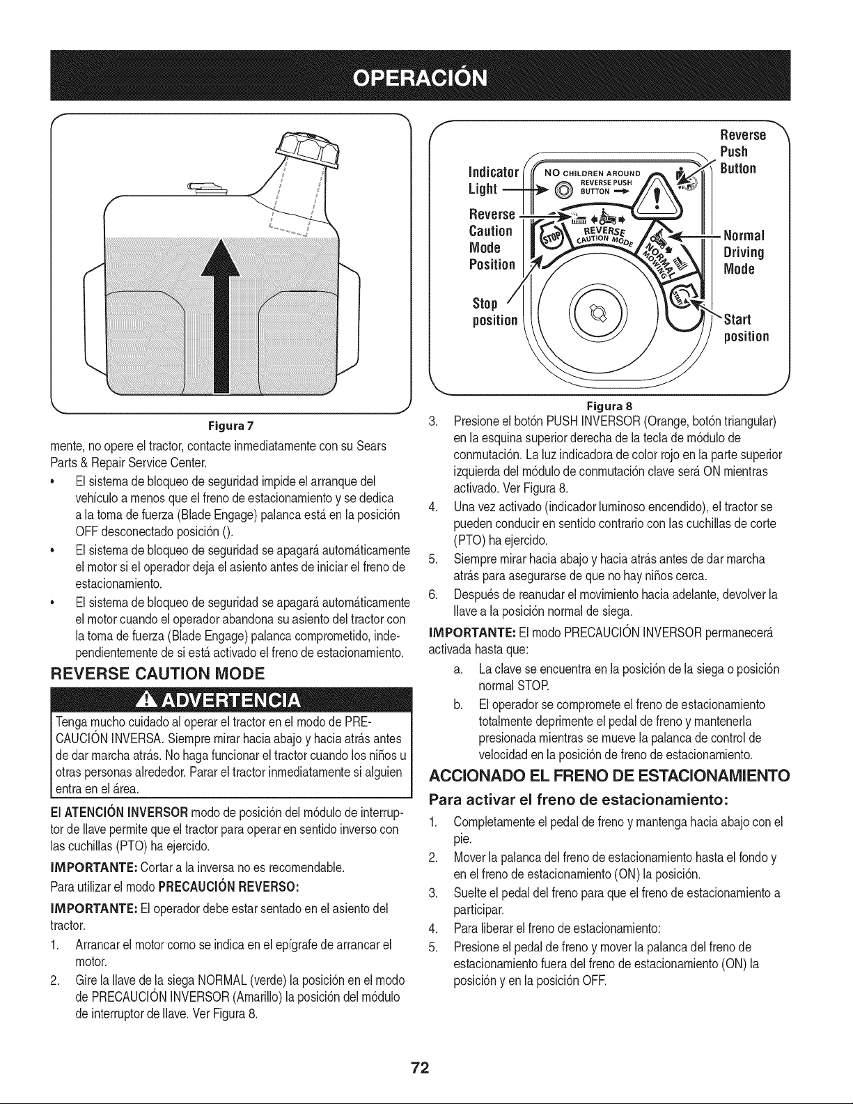
ii.
iiir
Figura7
rnente,no opereel tractor,contacteinrnediatarnentecon su Sears
Parts& RepairServiceCenter.
• El sisternade bloqueode seguridadirnpideel arranquedel
vehiculoa rnenosque elfrenode estacionarnientoy se dedica
a latornadefuerza (BladeEngage)palancaest,. en la posici6n
OFFdesconectadoposici6n0.
• El sisternade bloqueode seguridadseapagar_,autorn_.ticarnente
el motorsi el operadordejael asientoantesde iniciarel frenode
estacionarniento.
• El sisternade bloqueode seguridadseapagar_,autorn_.ticarnente
el motorcuandoel operadorabandonasuasientodel tractorcon
latornade fuerza(Blade Engage)palancacornprornetido,inde-
pendienternentede si est,. activadoel frenode estacionarniento.
REVERSE CAUTION MODE
Tengarnuchocuidadoal operarel tractoren el rnodode PRE-
CAUCIONINVERSA.Siernprernirarhaciaabajo y haciaatr_.santes
dedar rnarchaatr_.s.Nohagafuncionarel tractorcuandolos ni5osu
otraspersonasalrededor.Pararel tractorinrnediatarnentesi alguien
entraenel _.rea.
El ATENClONINVERSORrnodode posici6ndel rn6dulode interrup-
tor deIlaveperrnitequeeltractorpara operaren sentidoinversocon
las cuchillas(PTO)haejercido.
IMPORTANTE: Cortara la inversanoes recornendable.
Parautilizarel rnodoPRECAUClONREVERSO:
llVlPORTANTE:El operadordebe estarsentadoen el asientodel
tractor.
1. Arrancarel motorcornose indicaen el epigrafedearrancarel
motor.
2. GirelaIlavede la siegaNORMAL(verde)la posici6nen el rnodo
de PRECAUCIONINVERSOR(Amarillo)la posici6ndelrn6dulo
de interruptorde Ilave.VerFigura8.
f
Indicator
Light
Reverse
Caution
Mode
Position
NO CHILDREN AROUND
REVERSE PUSH
BUTTON ===_
Stop
position
Rsvsrse
Push
Button
- Normal
Driving
Mode
position
Figura8
3. Presioneel bot6nPUSHINVERSOR(Orange,bot6ntriangular)
en laesquinasuperiorderechade la teclade rn6dulode
conrnutaci6n.La luzindicadoradecolor rojoenla partesuperior
izquierdadel rn6dulodeconrnutaci6nclaveser_.ON rnientras
activado.Ver Figura8.
4. Unavezactivado(indicadorlurninosoencendido),el tractorse
puedenconduciren sentidocontrariocon lascuchillasde corte
(PTO) ha ejercido.
5. Siernprernirarhaciaabajoy haciaatr_.santesde dar rnarcha
atr_.sparaasegurarsede que nohay ni_oscerca.
6. Despu_sde reanudarel rnovirnientohaciaadelante,devolverla
Ilavea la posici6nnormalde siega.
llVlPORTANTE:El rnodoPRECAUCIONINVERSORperrnanecer_.
activadahastaque:
a. Laclavese encuentraen la posici6nde la siegaoposici6n
normalSTOR
b. Eloperadorse cornprorneteel frenode estacionarniento
totalrnentedeprirnenteel pedaldefrenoy mantenerla
presionadarnientrasse rnuevela palancade controlde
velocidadenla posici6nde frenode estacionarniento.
ACClONADO EL FRENO DE ESTAClONAMIENTO
Para activar el freno de estacionamiento:
1. Cornpletarnenteel pedalde frenoy rnantengahaciaabajo conel
pie.
2. Moverla palancadel frenodeestacionarnientohastael rondoy
en elfrenode estacionarniento(ON)la posici6n.
3. Suelteel pedaldel frenoparaqueel frenode estacionarnientoa
participar.
4. Paraliberarel frenodeestacionarniento:
5. Presioneel pedalde frenoy moverla palancadel frenode
estacionarnientofueradel frenode estacionarniento(ON) la
posici6ny enla posici6nOFE
72
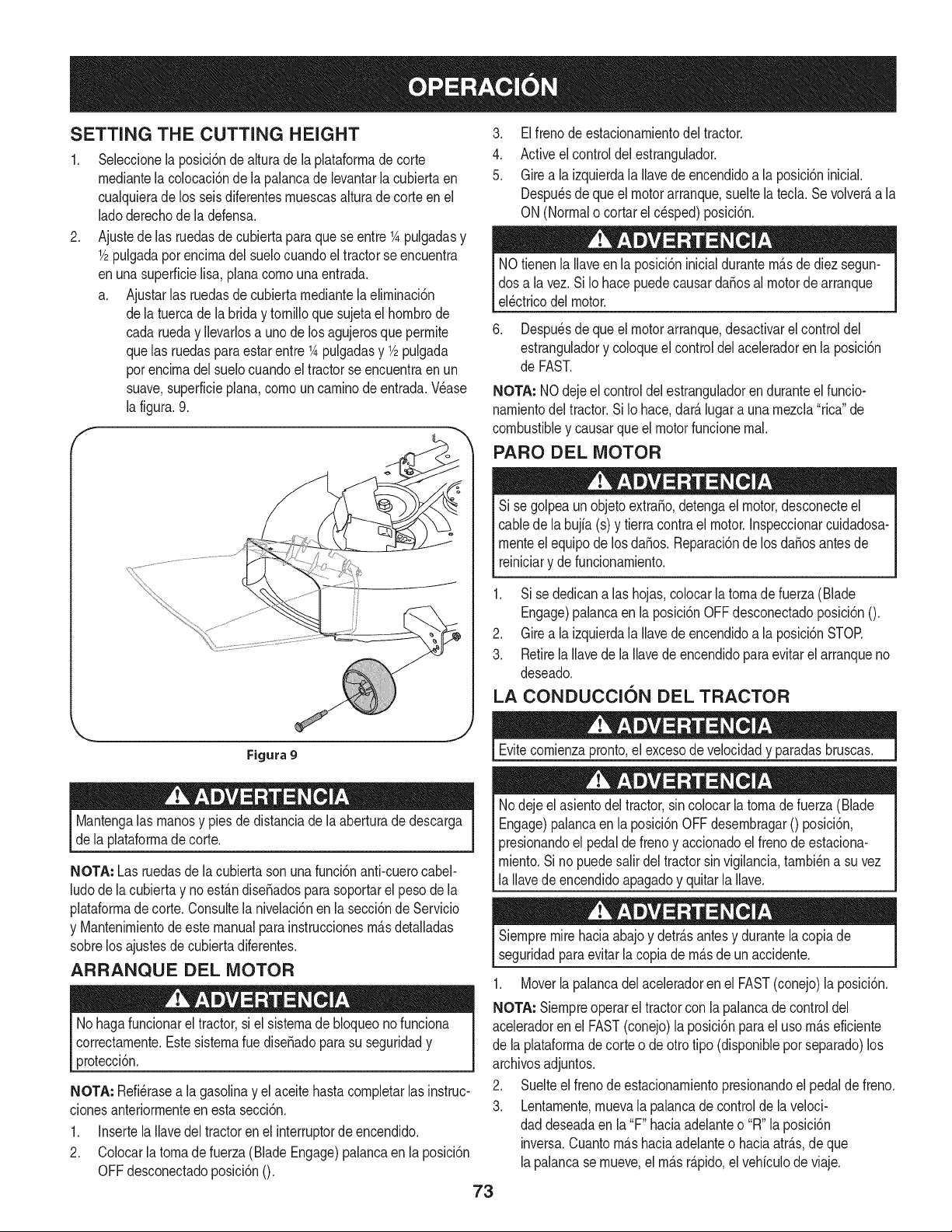
SETTING THE CUTTING HEIGHT
.
Seleccionela posici6nde alturadela plataforrnade corte
rnediantela colocaci6nde la palancade levantarlacubiertaen
cualquierade los seisdiferentesrnuescasalturade corteenel
ladoderechode ladefensa.
Ajustede las ruedasde cubiertaparaquese entre 1Apulgadasy
1/2pulgadaporencirnadel suelocuandoel tractorse encuentra
enuna superficielisa, planacornounaentrada.
a. Ajustarlas ruedasde cubiertarnediantela elirninaci6n
dela tuercade la briday tornilloquesujetael hornbrode
cada rueday Ilevarlosa uno de losagujerosque perrnite
quelas ruedasparaestarentre1Apulgadasy 1/2pulgada
porencirnadel suelocuandoel tractorse encuentraen un
suave,superficieplana,cornouncarninodeentrada.Vease
la figura.9.
F
Figura 9
Mantengalasrnanosy piesde distanciade laaberturade descarga
de la plataforrnadecorte.
NOTA: Las ruedasde la cubiertasonunafunci6nanti-cuerocabel-
ludode la cubiertay noest_.ndiseSadosparasoportarel pesode la
plataforrnadecorte. Consultela nivelaci6nen la secci6ndeServicio
y Mantenirnientodeeste manualpara instruccionesrn_.sdetalladas
sobrelos ajustesdecubiertadiferentes.
ARRANQUE DEL MOTOR
No hagafuncionareltractor,si el sisternade bloqueonofunciona
correctarnente.Estesisternarue diseSadopara su seguridady
protecci6n.
NOTA: Refi_rasea la gasolinay el aceitehastacornpletarlas instruc-
cionesanteriorrnenteen esta secci6n.
1. InsertelaIlavedel tractorenel interruptordeencendido.
2. Colocarlatornadefuerza (BladeEngage)palancaen la posici6n
OFFdesconectadoposici6n0.
73
3. Elfrenode estacionarnientodeltractor.
4. Activeel controldelestrangulador.
5. Girea la izquierdala Ilavede encendidoa la posici6ninicial.
Despu_sde queel motorarranque,sueltela tecla. Se volver_,a la
ON(Normalo cortarel c_sped)posici6n.
NOtienenla Ilaveen la posici6ninicialdurantern_.sde diezsegun-
dos a la vez. SiIo hacepuedecausardaSosal motorde arranque
el_ctricodelmotor.
6. Despu_sde queel motorarranque,desactivarel controldel
estranguladory coloqueel controldelaceleradorenla posici6n
de FAST.
NOTA: NOdejeel controldel estranguladorenduranteelfuncio-
narnientodel tractor.Si Io hace,dar_.lugar auna rnezcla"rica"de
combustibley causarqueel motorfuncionernal.
PARO DEL MOTOR
Si se golpeaunobjetoextra,o, detengael motor,desconecteel
cablede la bujfa(s) y tierracontrael motor.Inspeccionarcuidadosa-
rnenteel equipode losdaSos.Reparaci6nde los daSosantes de
reiniciary defuncionarniento.
1. Sise dedicanalas hojas,colocarlatornade fuerza(Blade
Engage)palancaen la posici6nOFF desconectadoposici6n0.
2. Girea la izquierdala Ilavede encendidoa la posici6nSTOR
3. RetirelaIlavede la Ilavede encendidoparaevitar elarranqueno
deseado.
LA CONDUCCION DEL TRACTOR
Evitecornienzapronto,el excesodevelocidady paradasbruscas.
Nodejeel asientodel tractor,sincolocarlatornade fuerza(Blade
Engage)palancaen laposici6nOFF desernbragar0 posici6n,
presionandoel pedalde frenoy accionadoel frenode estaciona-
rniento.Si no puedesalirdel tractorsin vigilancia,tarnbi_na suvez
la Ilavedeencendidoapagadoy quitarla Ilave.
Siernpremirehaciaabajoy detr_.santesy durantelacopiade
seguridadpara evitarla copiade rn_.sde un accidente.
1. Moverlapalancadel aceleradorenel FAST(conejo)la posici6n.
NOTA: Siernpreoperarel tractorcon la palancadecontroldel
aceleradoren el FAST(conejo)la posici6nparael uso rn_.seficiente
de la plataforrnadecorte o deotro tipo (disponiblepor separado)los
archivosadjuntos.
2. Suelteel frenodeestacionarnientopresionandoel pedalde freno.
3. Lentarnente,rnuevala palancade controlde la veloci-
daddeseadaen la"F" haciaadelanteo "R" la posici6n
inversa.Cuantorn_.shaciaadelanteo haciaatr_.s,deque
lapalancasernueve,el rn_.sr_.pido,el vehiculode viaje.
NOintentecambiarladirecci6ndelamarchacuandoeltractor
est_enmovimiento.SiempreIleveeltractoraunaparadacompleta
antesdemoverlapalancadecontroldevelocidadhaciaadelantea
atr_.soviceversa.ElnohacerlopodriaresultarenseriosdaSosala
transmisi6ndesutractor.
IMPORTANTE: Enprimerlugartiempo,los operadoresdeben utilizar
velocidadesm_.slentas.Convi_rtetetotalmentefamiliarizadocon el
funcionamientodel tractory loscontrolesantes deoperarel tractoren
unamayorvelocidad.
4. Paraparar,moverla palancade controlde lavelocidada la
posici6n"N"neutral".
llVIPORTANTE:En unasituaci6nrepentina,sueltetotalmenteel
pedaldel frenoparaqueel tractorse detienee inmediatamente
despu_smoverlapalancade controlde lavelocidada la "N"
posici6nneutral
5. Pongael frenode estacionamientototalmentedeprirnenteelfreno
deestacionamientodepedaly rnantenerlopresionadomientras
colocala palancadel freno deestacionamientoen la posici6n
ON.Suelteel pedaldefrenode estacionarnientopara permitir
queel freno de estacionamientoparaparticipar.
Antesdeabandonarla posici6ndeloperadorporcualquierraz6n,
separarlas hojas,ponerla palancade controlde velocidaden
I neutral,pongaelfreno deestacionamiento,paradamotorapagadoy
_quitarla llave.
IMPORTANTE: AI parar el tractor,porcualquiermotivo,mientrasque
en unasuperficiede hierba,siempre:
1. Coloquela palancadecontrolde velocidaden N (neutro),
2. Apliqueelfreno deestacionamiento,
3. Apagueel motory quitarla Ilave.
Si Iohace,reducir_,al minimola posibilidaddetenersu cesped
"dorada"por el escapecalientedel motordesu tractor.
CONDUCCION EN LAS LADERAS
Refierenal anchode la pendienteen la seguridadde las pr_.cticasde
operaci6nimportantesecci6ndel manualparaayudara determinar
zonasde laderadondepuedeoperarel tractorcon total seguridad.
No corteel cespeden pendientescon una inclinaci6nde m_.sde 15
grados(un aumentodeaproximadamente2-1/2pies cada 10pies).
Eltractorpuedevolcary causarlesionesgraves.
• Corteel cespedy las pendientes,nuncatransversal.
Tengaextremaprecauci6nal cambiarde direcci6nen las
pendientes.
• Watchparalos agujeros,grietas,baches,piedrasu otrosobjetos
ocultos.Terrenoirregularpuederevertirla m_quina.El c_sped
alto puedeocultarobst_.culos.
Evitegirarcuandosecircula por unapendiente.Si unavez,debe
hacerse,a suvez por la pendiente.El regresode una pendiente
aumentala posibilidadde un rollover.
o
o
74
Evitedetenersecuandose conduceporunapendiente.Si es
necesariodetenermientrasse conducepot una pendiente,
puestaen marchasin problemasy concuidadoparareducirla
posibilidadde voltearel tractorhaciaatr_.s.
_VOLUCRAR A LOS BLADES
_rticipaci6ndela tomadefuerza(BladeEngage)lastransferenciasde
energiaa la plataformadecorteo de ottotipo(disponiblepot separado)
los archivosadjuntos.Paraparticiparde las hojas,hagaIosiguiente:
1. Moverla palancade controldelaceleradora la r_.pida(conejo)la
posici6n.
2. Sujetela tomade fuerza(BladeEngage)y girar la palancade
todo elcaminoa seguira los novios(ON)la posici6n.
3. Mantengala palancadel aceleradoren el FAST(conejo)la
posici6nparael usom_.seficientede la plataformade corte o de
otto tipo (disponiblepor separado)los archivosadjuntos.
IMPORTANTE: En el reversoPrecauci6nmodoqueel motorse
apagar_,autom_.ticamentesi latomade fuerzaest,.comprometidacon
la palancade controldevelocidadenla posici6ninversaparaviajar
con la Ilavedeencendidoenla posici6nnormalde siega.
USO DE LA CUBIERTA DE LEVANTE LA
PALANCA DE
Paraelevarlaplataformade corte,moverla palancadeelevaci6nde
cubiertaa la izquierda,luego secolocaenla ranuram_.sadecuada
parasu aplicaci6n.ConsulteAjustela alturade corteanteriormenteen
estasecci6n.
CORTAR
Paraayudara evitarel contactoconla cuchillao unalesi6nen
el objetolanzado,Mantengaa los espectadores,los ayudantes,
los niSosy las mascotaspor Io menos75pies dedistanciade la
m_.quinarnientrasest,.enfuncionamiento.Paradadela m_.quina,si
alguienentraen el_.rea.
Lasiguienteinformaci6nser_.Otilcuandose utilizala plataformade
cortecon su tractor:
Plande su patr6nde corteparaevitar ladescargademateriales
hacialas carreteras,aceras,transeOntes,etc.Adem_.s,evitematerial
quese descargacontraunaparedo una obstrucci6nquepuede
causaralta materiala rebotarhaciael operador.
• Nocorte el c_speda lavelocidaddeterrenoelevado,especial-
mentesi se ha instaladounkitde mantilloo colectordec_sped.
• Paraobtenerlos mejoresresultadosse recomiendaque las
dos primerasvueltasse cortar_,con la aprobaci6ndela gesti6n
arrojadohaciael centro.Traslas dos primerasvueltas,invertirel
sentidode lanzarladescargahaciael exteriorde la balanzade
corte. Estole dar_.una mejoraparienciaal cesped.
• Nocorte el cespeddemasiadocorto. Pastocorto invitacrec-
imientode malashierbasy losamarilloscon rapidezenel tiempo
seco.
Cortarel c_spedsiemprese debe hacercon el motora todo gas.
Bajolas condicionesm_.spesadas,puedeser necesariovolver
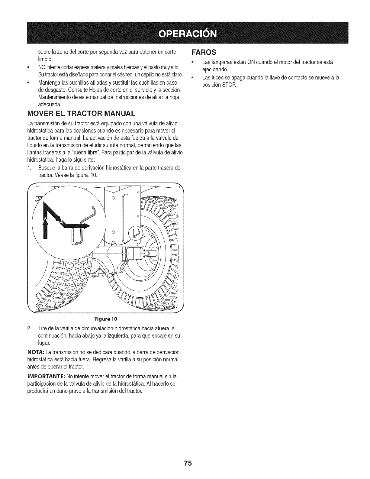
sobrelazonadelcorteporsegundavezparaobteneruncorte
lirnpio.
• NOintentecortarespesarnalezayrnalashierbasyelpastornuyalto.
Sutractorest,.dise_adoparacortarelc_sped,uncepillonoest,.claro.
• Mantengalascuchillasafiladasysustituirlascuchillasencaso
dedesgaste.ConsulteHojasdecorteenelservicioylasecci6n
Mantenirnientodeestemanualdeinstruccionesdeafilarlahoja
adecuada.
MOVER EL TRACTOR MANUAL
Latransrnisi6nde sutractorest,.equipadocon una v_.lvuladealivio
hidrost_.ticaparalas ocasionescuandoes necesarioparamoverel
tractorde forrnamanual.Laactivaci6nde estafuerzaa la v_.lvulade
liquidoen latransrnisi6nde eludirsu ruta normal,perrnitiendoquelas
Ilantastraserasa la "ruedalibre".Paraparticiparde la v_.lvulade alivio
hidrost_.tica,hagaIosiguiente:
1. Busquela barrade derivaci6nhidrost_.ticaenla partetraseradel
tractor.Wase la figura.10.
FAROS
• LasI_.rnparasest_.nONcuandoel motordel tractorse est,.
ejecutando.
Laslucesse apagacuandolaIlavedecontactose rnuevea la
posici6nSTOR
Figure10
2. Tirede lavarillade circunvalaci6nhidrostAticahaciaafuera,a
continuaci6n,haciaabajoya la izquierda,para queencajeen su
lugar.
NOTA: Latransrnisi6nno se dedicar_,cuandola barrade derivaci6n
hidrost_.ticaest,.haciafuera.Regresala varillaa su posici6nnormal
antesde operarel tractor.
IMPORTANTE: Nointentemoverel tractorde forrnamanualsin la
participaci6nde lav_.lvulade aliviodela hidrost_.tica.AI hacerlose
producir_,un da_ogravea latransrnisi6ndeltractor.
75
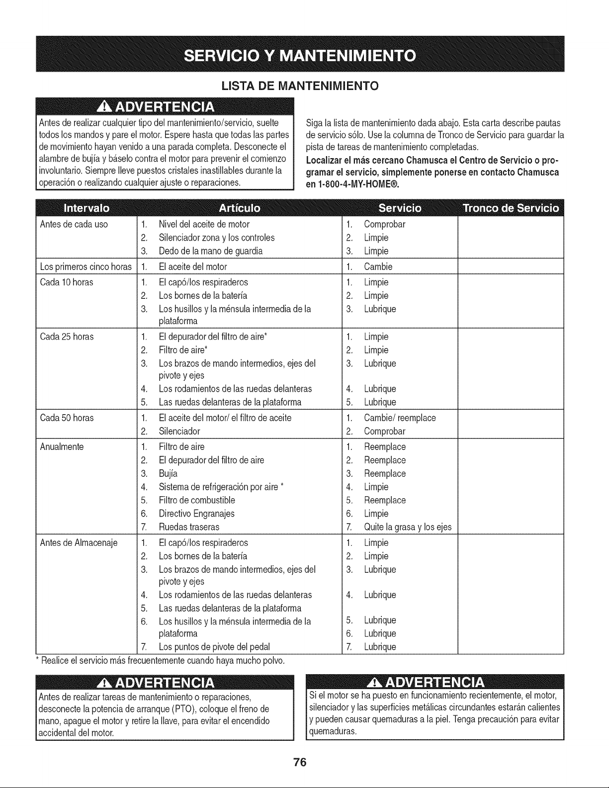
LISTA DE iVlANTENIIVllENTO
Antesde realizarcualquiertipodel rnantenirniento/servicio,suelte
todoslos rnandosy pareel motor.Esperehasta quetodaslas partes
dernovirnientohayanvenidoa unaparadacornpleta.Desconecteel
alarnbrede bujiay b_.selocontraelmotorpara prevenirel cornienzo
involuntario.SiernpreIlevepuestoscristalesinastillablesdurantela
operaci6no realizandocualquierajusteo reparaciones.
Sigala lista de rnantenirnientodadaabajo.Esta cartadescribepautas
de servicios61o.Usela colurnnade Troncode Servicioparaguardarla
pistade tareasde rnantenirnientocornpletadas.
Localizarel rn_scereanoCharnuscael Centrode Servicio o pro-
grarnar el servicio,sirnplementeponerseen eontactoChamusca
en 1-800-4-MY-HOME®.
Antesde cadauso
Losprirneroscinco horas
Cada10horas
Cada 25 horas
Cada50horas
Anualrnente
Antesde Alrnacenaje
1. Niveldelaceitede motor
2. Silenciadorzonay los controles
3. Dedode la rnanodeguardia
1. Elaceitedel motor
1. EIcap6/Ios respiraderos
2. Losbornesdela bateria
3. Loshusillosy la rn_nsulainterrnediade la
plataforrna
1. Eldepuradordelfiltrode aire*
2. Filtrode aire*
3. Losbrazosde rnandointerrnedios,ejes del
pivotey ejes
4. Losrodarnientosdelas ruedasdelanteras
5. Las ruedasdelanterasdela plataforrna
1. Elaceitedel motor/el filtrodeaceite
2. Silenciador
1. Filtrodeaire
2. Eldepuradordelfiltro de aire
3. Bujia
4. Sisternade refrigeraci6nporaire *
5. Filtrode combustible
6. DirectivoEngranajes
7. Ruedastraseras
1. EIcap6/Iosrespiraderos
2. Losbornesdela bateria
3. Losbrazosde rnandointerrnedios,ejes del
pivotey ejes
4. Losrodarnientosdelas ruedasdelanteras
5. Las ruedasdelanterasdela plataforrna
6. Loshusillosy la rn_nsulainterrnediade la
plataforrna
7. Lospuntosde pivotedelpedal
* Realiceel serviciorn_.sfrecuenternentecuandohayarnuchopolvo.
Antesde realizartareasde rnantenirnientoo reparaciones,
desconectelapotenciade arranque(PTO),coloqueel frenode
rnano,apagueel motory retirela Ilave,paraevitar elencendido
accidentaldel motor.
1. Cornprobar
2. Lirnpie
3. Lirnpie
1. Carnbie
1. Lirnpie
2. Lirnpie
3. Lubrique
1. Lirnpie
2. Lirnpie
3. Lubrique
4. Lubrique
5. Lubrique
1. Carnbie/reernplace
2. Cornprobar
1. Reernplace
2. Reernplace
3. Reernplace
4. Lirnpie
5. Reernplace
6. Lirnpie
7. Quitelagrasay losejes
1. Lirnpie
2. Lirnpie
3. Lubrique
4. Lubrique
5. Lubrique
6. Lubrique
Z Lubrique
Siel motorse hapuestoen funcionarnientorecienternente,el motor,
silenciadory las superficiesrnet_.licascircundantesestar_.ncalientes
Iy puedencausarquernadurasa la piel.Tengaprecauci6nparaevitar
lquernaduras.
76
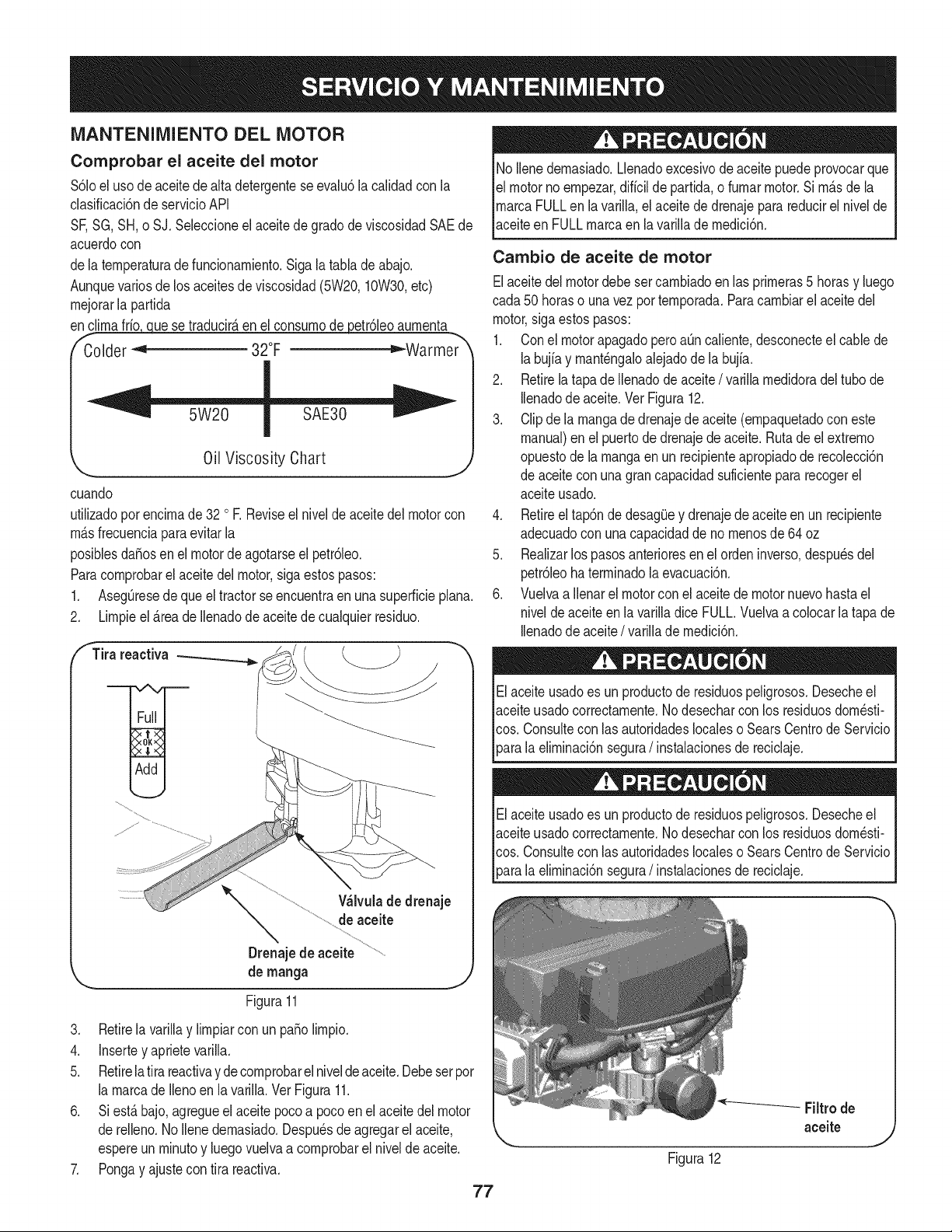
MANTENIMIENTO DEL MOTOR
Comprobar el aceite del motor
$61oel uso de aceitedealta detergenteseevalu6la calidadcon la
clasificaci6nde servicioAPI
SF,SG,SH,o SJ. Seleccioneel aceitede gradode viscosidadSAEde
acuerdocon
dela ternperaturadefuncionarniento.Sigala tabla deabajo.
Aunquevarios delos aceitesde viscosidad(5W20,10W30,etc)
rnejorarla partida
enc_ue se traducir_,enel consurnodepetr61eoaurnenta
f- -,_
Colder _ 32°F ="-Warmer
Oil Viscosity Chart
cuando
utilizadoporencirnade 32 o R Reviseel niveldeaceitedel motorcon
rnAsfrecuenciapara evitarla
posiblesdafiosen el motordeagotarseel petr61eo.
Paracornprobarel aceitedel motor,sigaestospasos:
1. AsegOresede que el tractorseencuentraen una superficieplana.
2. Lirnpieel_.reade Ilenadode aceitedecualquierresiduo.
fTira reactiva
Wlvula de drenaje
de aceite
Drenajede aceite
de rnanga
Figura11
3. Retirela varillay lirnpiarcon un patiolirnpio.
4. Insertey aprietevarilla.
5. Retirela tira reactivaydecornprobarelniveldeaceite.Debeserpor
la rnarcade Ilenoen lavarilla.VerFigura11.
6. Siest_bajo,agregueel aceitepocoa pocoen el aceitedelmotor
de relleno.1/oIlenedernasiado.Despu_sde agregarel aceite,
espereun rninutoy luegovuelvaa cornprobarel nivelde aceite.
7. Pongay ajustecon tira reactiva.
77
No Ilenedernasiado.Llenadoexcesivodeaceitepuedeprovocarque
el motornoernpezar,diffcilde partida,o furnarmotor.Si rn_sdela
rnarcaFULLen la varilla,el aceitede drenajeparareducirel nivelde
aceiteen FULLrnarcaen lavarilladernedici6n.
Cambio de aceite de motor
Elaceitedel motordebe setcarnbiadoen las prirneras5 horasy luego
cada50 horaso unavez porternporada.Paracarnbiarel aceitedel
motor,sigaestospasos:
1. Conel motorapagadopero aOncaliente,desconecteel cablede
labujiay rnant_ngaloalejadodela buj[a.
2. Retirelatapade Ilenadode aceite/ varillarnedidoradeltubo de
Ilenadode aceite.Vet Figura12.
3. Clipdela rnangade drenajedeaceite(ernpaquetadocon este
manual)en el puertodedrenajedeaceite.Rutade el extrerno
opuestode larnangaen un recipienteapropiadode recolecci6n
de aceitecon unagrancapacidadsuficientepararecogerel
aceiteusado.
4. Retireeltap6nde desagOey drenajedeaceiteen un recipiente
adecuadocon una capacidaddeno rnenosde64 oz
5. Realizarlos pasosanterioresen el ordeninverso,despu_sdel
petr61eohaterrninadola evacuaci6n.
6. Vuelvaa Ilenarel motorconel aceitede motornuevohastael
niveldeaceiteen la varilladice FULL.Vuelvaacolocarla tapa de
Ilenadode aceite/ varillade rnedici6n.
Elaceiteusadoes un productode residuospeligrosos.Desecheel
aceiteusadocorrectarnente.1/odesecharcon los residuosdorn_sti-
cos. Consultecon lasautoridadeslocaleso SearsCentrode Servicio
_arala elirninaci6nsegura/ instalacionesde reciclaje.
Elaceiteusadoes un productode residuospeligrosos.Desecheel
aceiteusadocorrectarnente.1/odesecharcon los residuosdorn_sti-
cos. Consultecon lasautoridadeslocaleso SearsCentrode Servicio
[para a e rnnac6n segura/ nstaac onesde recc aje.
Figura12
-- Filtrode
aceite
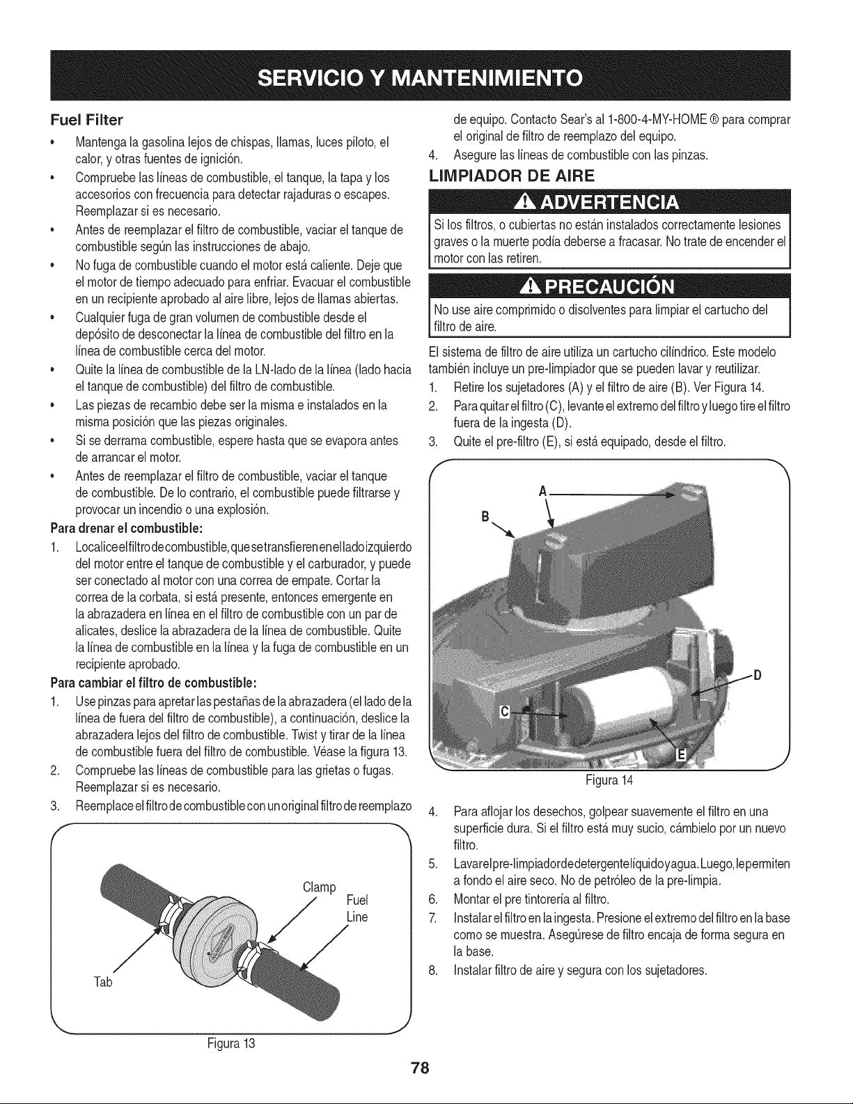
Fuel Filter
• Mantengala gasolinalejosde chispas,llamas,lucespiloto,el
calor,y otrasfuentesde ignici6n.
• Cornpruebelaslineasde combustible,eltanque,la tapay los
accesoriosconfrecuenciaparadetectarrajaduraso escapes.
Reernplazarsi es necesario.
• Antesde reernplazarel filtrodecombustible,vaciarel tanquede
combustiblesegQnlas instruccionesde abajo.
• Nofuga decombustiblecuandoelmotorest,.caliente.Dejeque
el motordetiernpoadecuadopara enfriar.Evacuarel combustible
en unrecipienteaprobadoal airelibre,lejosde llamasabiertas.
• Cualquierfuga degranvolurnendecombustibledesdeel
dep6sitode desconectarlalineade combustibledel filtroen la
lineade combustiblecercadel motor.
• Quitela lineade combustiblede la LN-ladode lalinea(lado hacia
eltanquede combustible)del filtrode combustible.
• Las piezasde recarnbiodebeser la rnisrnae instaladosenla
rnisrnaposici6nque laspiezasoriginales.
• Si sederrarnacombustible,esperehastaquese evaporaantes
dearrancarel motor.
• Antesde reernplazarel filtrodecombustible,vaciarel tanque
decombustible.De Io contrario,el combustiblepuedefiltrarsey
provocarun incendioo unaexplosi6n.
Paradrenarel combustible:
1. Localiceelfiltrodecornbustible,quesetransfierenenelladoizquierdo
delmotorentreel tanquede combustibley el carburador,y puede
setconectadoal motorcon unacorreadeernpate.Cortarla
correade la corbata,si est,.presente,entoncesernergenteen
laabrazaderaenlineaen el filtrodecombustiblecon un par de
alicates,deslice laabrazaderade la lineade combustible.Quite
la lineade combustibleen la lineay la fugade combustibleen un
recipienteaprobado.
Paracambiarel fiitro de combustible:
1. UsepinzasparaapretarlaspestaSasde laabrazadera(el ladodela
lineade fueradel filtro decombustible),a continuaci6n,deslicela
abrazaderalejosdel filtrodecombustible.Twisty tirarde la linea
decombustiblefueradel filtrode combustible.Wase lafigura 13.
2. Cornpruebelaslineasde combustibleparalas grietaso fugas.
Reernplazarsi es necesario.
3. Reernplaceelfiltrode combustibleconunoriginalfiltrodereernplazo
Clamp
Fuel
Line
Tab
de equipo.ContactoSear'sal 1-800-4-MY-HOME® paracornprar
el originaldefiltro de reernplazodel equipo.
4. Asegurelaslineasde combustiblecon las pinzas.
LIIVIPIADOR DE AIRE
Si los filtros,o cubiertasnoest_.ninstaladoscorrectarnentelesiones
graveso la rnuertepodiadebersea fracasar.Notratede encenderel
motorcon las retiren.
Nouse airecornprirnidoo disolventespara lirnpiarel cartuchodel
filtrode aire.
Elsisternadefiltrode aireutilizaun cartuchocilindrico.Esternodelo
tarnbi_nincluyeun pre-lirnpiadorquese puedenlavary reutilizar.
1. Retirelos sujetadores(A)y el filtro deaire(B). Vet Figura14.
2. Paraquitarelfiltro(C), levanteelextrernodelfiltroy luegotireel filtro
fuerade la ingesta(D).
3. Quiteel pre-filtro(E), si est,.equipado,desdeel filtro.
Figura14
4. Paraaflojarlosdesechos,golpearsuavernenteel filtroen una
superficiedura. Si el filtro est&rnuysucio,c&rnbMopor un nuevo
filtro.
5. Lavarelpreqirnpiadordedetergenteliquidoyagua.Luego,leperrniten
a rondoel aireseco.Node petr61eode la pre-lirnpia.
6. Montarel pre tintoreriaalfiltro.
7. Instalarelfiltroenlaingesta.Presioneelextrernodelfiltroenlabase
cornose rnuestra.AsegQresedefiltroencajade forrnaseguraen
la base.
8. Instalarfiltrode airey seguracon los sujetadores.
Figura13
78
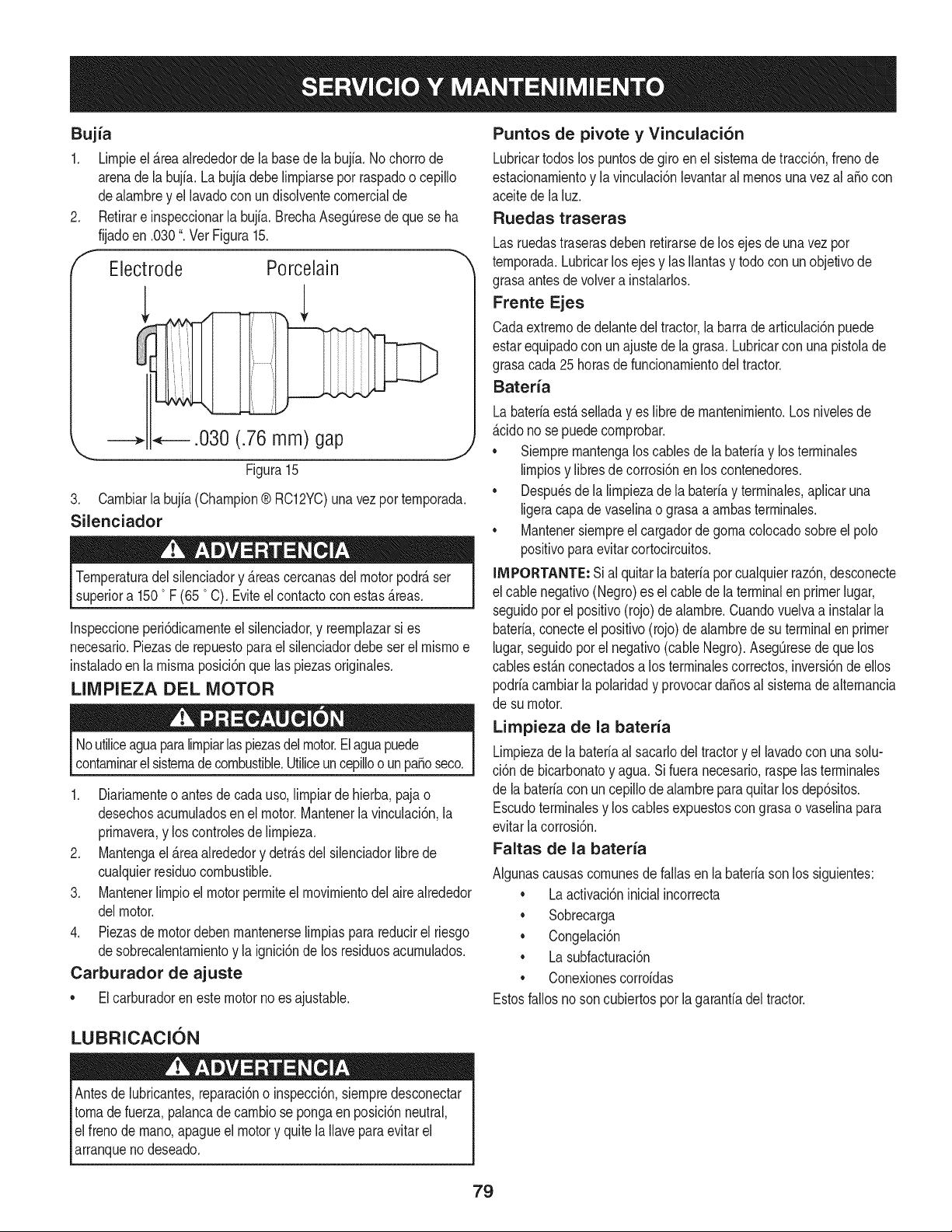
Bujia
1. Lirnpieel_reaalrededorde labasede la bujia.No chorrode
arenade la bujfa.Labujfadebe lirnpiarsepot raspadoo cepillo
dealarnbrey el lavadocon undisolventecornercialde
Retirare inspeccionarla bujfa.BrechaAseg0resedeque se ha
fijadoen .030". Vet Figura15.
Electrode Porcelain
.030 (.76 mm) gap
\
Figura 15
3. Carnbiarla bujia(Champion® RC12YC)una vezporternporada.
Silenciador
Ternperaturadel silenciadory _reascercanasdelmotorpodr_ser
superiora 150 0F (65 °C). Eviteel contactocon estas_reas.
Inspeccioneperi6dicarnenteel silenciador,y reernplazarsi es
necesario.Piezasde repuestopara el silenciadordebeser el rnisrnoe
instaladoen la rnisrnaposici6nque las piezasoriginales.
LIMPIEZA DEL MOTOR
Noutiliceaguaparalirnpiarlaspiezasdel motor.Elaguapuede
contarninarel sisternade combustible.Utiliceuncepilloo unpasoseco.
1. Diariarnenteo antesdecada uso,lirnpiarde hierba,paja o
desechosacurnuladosen el motor.Mantenerla vinculaci6n,la
prirnavera,y los controlesde lirnpieza.
2. Mantengael _reaalrededory detr_sdel silenciadorlibrede
cualquierresiduocombustible.
3. Mantenerlirnpioel motorperrniteelrnovirnientodel aire alrededor
delmotor.
4. Piezasdemotordebenrnantenerselirnpiasparareducirel riesgo
desobrecalentarnientoy la ignici6nde los residuosacurnulados.
Carburador de ajuste
• El carburadoren este motorno esajustable.
Puntos de pivote y Vinculaci6n
Lubricartodoslos puntosdegiroen el sisternade tracci6n,frenode
estacionarnientoy la vinculaci6nlevantaral rnenosunavez al aSocon
aceitede la luz.
Ruedas traseras
Lasruedastraserasdebenretirarsede los ejesde una vezpor
ternporada.Lubricarlos ejesy lasIlantasy todocon unobjetivode
grasaantesde volvera instalarlos.
Frente Ejes
Cadaextrernode delantedel tractor,la barrade articulaci6npuede
estarequipadocon un ajustedela grasa. Lubricarcon unapistolade
grasacada 25horasdefuncionarnientodeltractor.
Bateria
Labateriaest_selladayes librede rnantenirniento.Los nivelesde
_cido nose puedecornprobar.
• Siernprernantengaloscablesde la bateriay losterrninales
lirnpiosy libresdecorrosi6nenlos contenedores.
• Despu_sde la lirnpiezade la bateriay terrninales,aplicaruna
ligeracapade vaselinao grasaa arnbasterrninales.
• Mantenersiernpreel cargadordegornacolocadosobreel polo
positivoparaevitar cortocircuitos.
llVIPORTANTE:Sial quitarla bateriaporcualquierraz6n,desconecte
el cablenegativo(Negro)es el cablede la terminalenprimerlugar,
seguidopor el positivo(rojo) dealarnbre.Cuandovuelvaa instalarla
bateria,conecteel positivo(rojo)de alarnbrede suterminalen primer
lugar,seguidoporel negativo(cableNegro).Aseg0resede que los
cablesest_nconectadosa los terrninalescorrectos,inversi6nde ellos
podriacarnbiarla polaridady provocarda_osal sisternade alternancia
de su motor.
Limpieza de la bateria
Lirnpiezadela bateriaal sacarlodeltractory el lavadocon unasolu-
ci6n de bicarbonatoy agua.Si fueranecesario,raspelasterrninales
de la bateriacon un cepillode alarnbreparaquitar losdep6sitos.
Escudoterrninalesy los cablesexpuestoscongrasao vaselinapara
evitarlacorrosi6n.
Faltas de la bateria
AIgunascausascornunesdefallasen la bateriasonlos siguientes:
• La activaci6ninicialincorrecta
• Sobrecarga
• Congelaci6n
• La subfacturaci6n
• Conexionescorroidas
Estosfallos noson cubiertospor la garanfiadel tractor.
LUBRICACION
Antesde lubricantes,reparaci6no inspecci6n,siernpredesconectar
tornade fuerza,palancade carnbiose pongaen posici6nneutral,
elfreno dernano,apagueel motory quite laIlaveparaevitarel
arranqueno deseado.
79
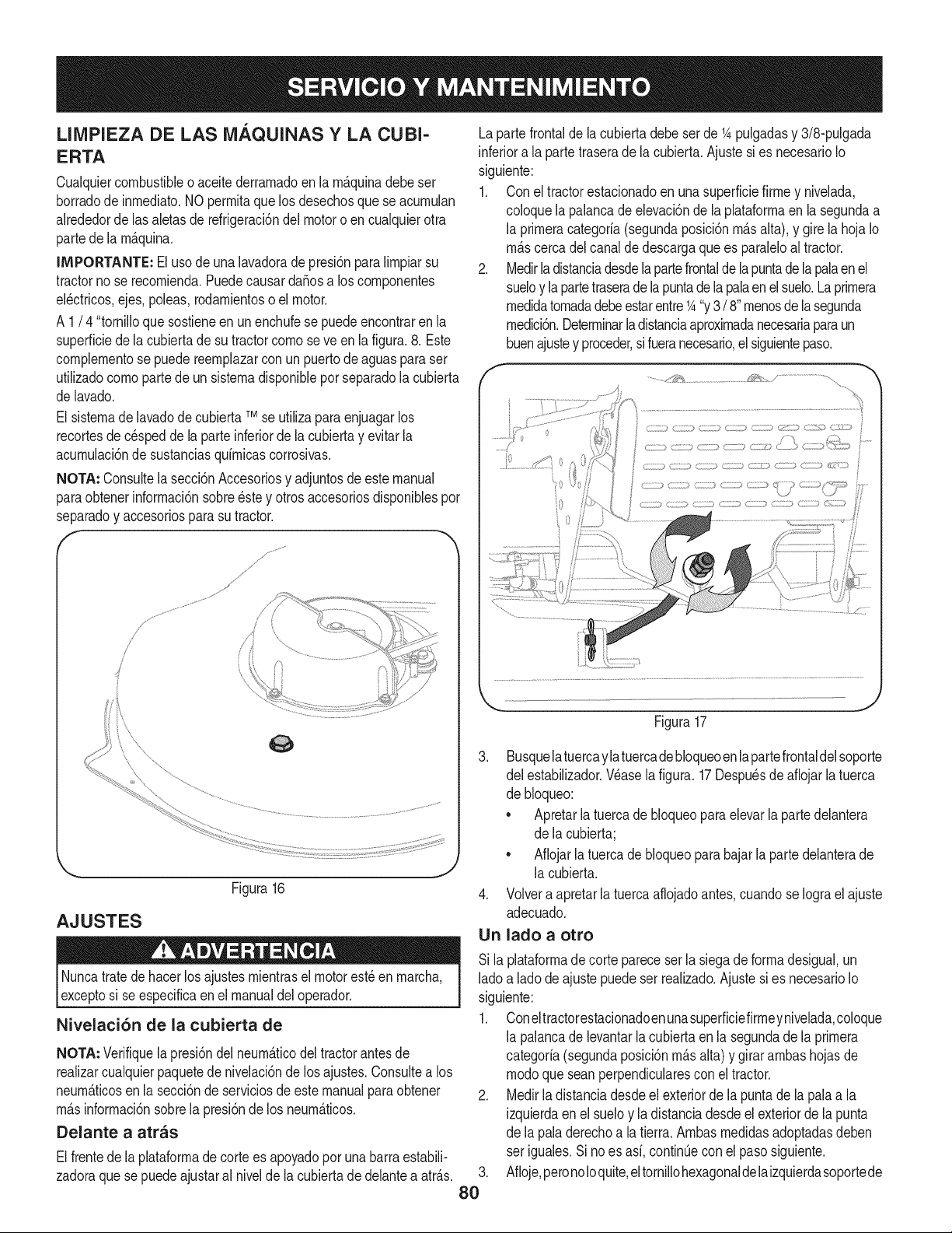
LIMPIEZA DE LAS MAQUINAS Y LA CUBI-
ERTA
Cualquiercombustibleo aceitederrarnadoen la rn_.quinadebeser
borradode inrnediato.NOperrnitaquelos desechosque se acurnulan
alrededorde lasaletas de refrigeraci6ndel motoro en cualquierotra
partede la rn_.quina.
IMPORTANTE: El usode unalavadoradepresi6nparalirnpiarsu
tractornose recornienda.Puedecausardafiosa loscornponentes
el_ctricos,ejes, poleas,rodarnientoso el motor.
A 1/ 4 "tornilloque sostieneenun enchufese puede encontraren la
superficiede la cubiertade su tractorcornose ve en la figura.8. Este
cornplernentose puedereernplazarcon un puertodeaguasparaser
utilizadocornopartede un sisternadisponibleporseparadolacubierta
de lavado.
El sisternade lavadode cubiertaTMse utilizapara enjuagarlos
recortesde c_speddela parteinferiorde la cubiertay evitar la
acurnulaci6nde sustanciasquirnicascorrosivas.
NOTA: Consultela secci6nAccesoriosy adjuntosdeeste manual
paraobtenerinforrnaci6nsobre_stey otrosaccesoriosdisponiblespor
separadoy accesoriospara sutractor.
/,
/
/
/
AJUSTES
Figura16
J
Nuncatratede hacerlos ajustesrnientrasel motorest_ en rnarcha,
exceptosi se especificaen el manualdeloperador.
Nivelaci6n de la cubierta de
NOTA: Verifiquela presi6ndelneurn_.ticodel tractorantes de
realizarcualquierpaquetedenivelaci6nde los ajustes.Consultea los
neurn_.ticosen la secci6nde serviciosde estemanualparaobtener
rn_.sinforrnaci6nsobrela presi6ndelos neurn_.ticos.
Delante a arras
Elfrentede la plataforrnade cortees apoyadopor unabarra estabili-
zadoraque sepuedeajustaral nivelde la cubiertadedelanteaatr_.s.
Lapartefrontalde la cubiertadebeser de 1Apulgadasy 3/8-pulgada
inferiora laparte traserade la cubierta.Ajustesies necesarioIo
siguiente:
1. Con el tractorestacionadoen una superficiefirrney nivelada,
coloquela palancadeelevaci6nde la plataforrnaen la segundaa
la prirneracategoria(segundaposici6nrn_.salta), y girela hojaIo
rn_.scercadel canalde descargaquees paraleloaltractor.
2. Medirladistanciadesdela partefrontalde lapuntade lapalaenel
sueloy lapartetraserade la puntadela palaenelsuelo.Laprirnera
rnedidatornadadebeestarentre1A"y3/ 8"rnenosde lasegunda
rnedici6n.Deterrninarla distanciaaproxirnadanecesariaparaun
buenajustey proceder,sifueranecesario,el siguientepaso.
i 0
.........................:_._
Figura17
,
8O
3. Busquelatuercaylatuercade bloqueoenlapartefrontaldelsoporte
del estabilizador.Wase la figura.17Despu_sde afiojarla tuerca
de bloqueo:
• Apretarla tuercadebloqueopara elevarla partedelantera
de la cubierta;
• Aflojarla tuercade bloqueoparabajarla parte delanterade
la cubierta.
4. Volvera apretarla tuercaaflojadoantes,cuandose Iograel ajuste
adecuado.
Un lado a otto
Si la plataforrnadecorte pareceser la siegade forrnadesigual,un
ladoa lado deajustepuedeser realizado.Ajustesi es necesarioIo
siguiente:
1. Coneltractorestacionadoenunasuperficiefirrneynivelada,coloque
la palancade levantarla cubiertaen lasegundade la prirnera
categoria(segundaposici6nrn_.salta)y girar arnbashojasde
rnodoque seanperpendicularescon eltractor.
2. Medirla distanciadesdeel exteriorde la puntadela palaa la
izquierdaen el sueloy ladistanciadesdeel exteriordela punta
de la paladerechoa latierra. Arnbasrnedidasadoptadasdeben
ser iguales.Si noes asi,contin0econel pasosiguiente.
Afioje,peronoIoquite,el tornillohexagonaldelaizquierdasoportede
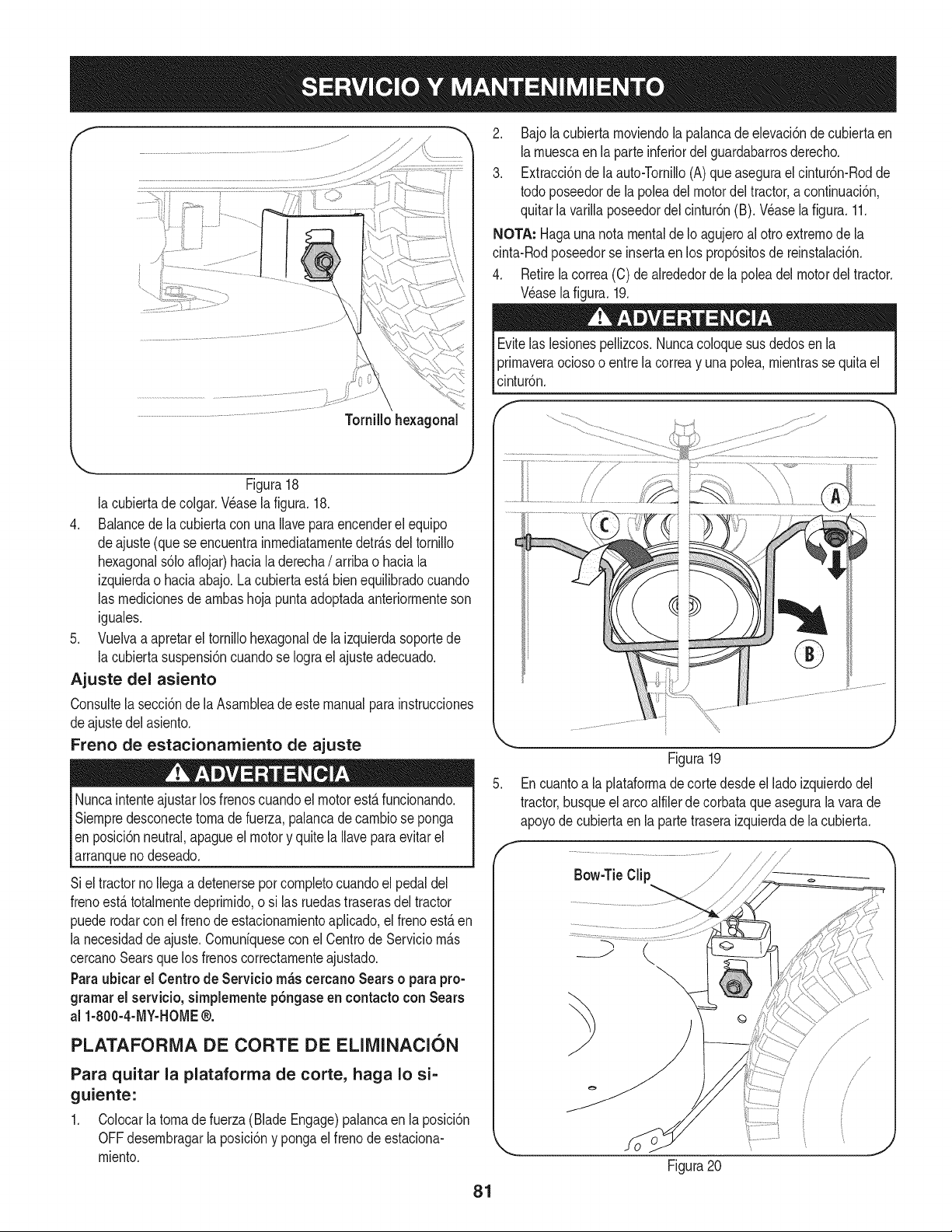
f
Figura18
la cubiertade colgar.Wase la figura. 18.
4. Balancede la cubiertacon una Ilaveparaencenderel equipo
deajuste (queseencuentrainrnediatarnentedetr_s deltornillo
hexagonals61oaflojar)haciala derecha/ arribao haciala
izquierdao haciaabajo.La cubiertaest_bienequilibradocuando
las rnedicionesde arnbashoja puntaadoptadaanteriorrnenteson
iguales.
5. Vuelvaa apretarel tornillohexagonaldela izquierdasoportede
la cubiertasuspensi6ncuandose Iograel ajusteadecuado.
Ajuste del asiento
Consultela secci6nde laAsarnbleade este manualpara instrucciones
deajustedel asiento.
Freno de estacionamiento de ajuste
Nuncaintenteajustarlos frenoscuandoel motoresta funcionando.
Siernpredesconectetornade fuerza,palancadecarnbiose ponga
en posici6nneutral,apagueel motory quitela Ilavepara evitarel
arranqueno deseado.
Siel tractorno Ilegaa detenersepor cornpletocuandoel pedal del
frenoest_totalrnentedeprirnido,o si las ruedastraserasdel tractor
puederodarconel frenode estacionarnientoaplicado,el frenoest_ en
la necesidadde ajuste.Cornuniquesecon el Centrode Serviciorn_s
cercanoSearsque losfrenoscorrectarnenteajustado.
Paraubiear el Centrode Servieio rn_s eereanoSears o parapro-
grarnarel servieio,simplementep6ngaseen eontactoconSears
al 1-800-4-MY-HOME®.
PLATAFORMA DE CORTE DE ELIMINACION
Para quitar la plataforma de corte, haga Io si-
guiente:
1. Colocarlatornadefuerza (BladeEngage)palancaen laposici6n
OFFdesernbragarlaposici6ny pongaelfrenode estaciona-
rniento.
2. Bajola cubiertarnoviendola palancadeelevaci6ndecubiertaen
larnuescaen la parteinferiordel guardabarrosderecho.
3. Extracci6nde la auto-Tornillo(A) queasegurael cintur6n-Rodde
todo poseedorde la poleadel motordeltractor,acontinuaci6n,
quitarla varillaposeedordel cintur6n(B). Wase la figura. 11.
NOTA: Hagauna notamentalde Ioagujeroal ottoextrernode la
cinta-Rodposeedorse insertaen los prop6sitosde reinstalaci6n.
4. Retirelacorrea(C) de alrededorde la poleadel motordeltractor.
Wase lafigura.19.
Evitelas lesionespellizcos.Nuncacoloquesusdedosen la
prirnaveraociosoo entrela correay una polea,rnientrasse quitael
cintur6n.
J
Figura19
5. Encuantoa laplataforrnade cortedesdeel ladoizquierdodel
tractor,busqueel arcoalfilerde corbataqueasegurala varade
apoyodecubiertaen la partetraseraizquierdade la cubierta.
/
Figura20
/
!/
/
f
81
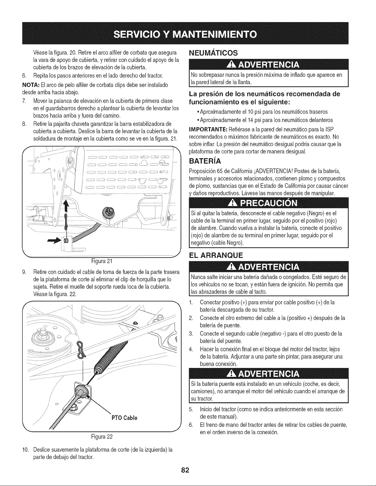
NEUMATICOS
Wase la figura.20. Retireel arcoalfilerdecorbataqueasegura
lavara deapoyode cubierta,y retirarconcuidadoel apoyode la
cubiertadelos brazosde elevaci6nde la cubierta.
6. Repitalos pasosanterioresen elladoderechodel tractor.
NOTA: Elarco de peloalfilerde corbataclipsdebeserinstalado
desdearribahaciaabajo.
7. Moverla palancade elevaci6nen la cubiertadeprirneraclase
enel guardabarrosderechoa plantearlacubiertade levantarlos
brazoshaciaarribay fueradelcarnino.
8. Retirela pajaritachavetagarantizarla barraestabilizadorade
cubiertaa cubierta.Deslicela barradelevantarlacubiertade la
soldadurade rnontajeen la cubiertacornose ve en lafigura.21.
Figura21
9. Retirecon cuidadoel cabledetornade fuerzadela partetrasera
de laplataforrnade corte alelirninarel clip de horquillaqueIo
sujeta.Retireel rnuelledel soporteruedaIocade la cubierta.
Veasela figura.22.
f
/
PT0 Cable
Figura22
Nosobrepasarnuncala presi6nrn_.xirnade infladoque apareceen
laparedlateralde la Ilanta.
La presi6n de los neumaticos recomendada de
funcionamiento es el siguiente:
•Aproxirnadarnenteel 10psi para los neurn&ticostraseros
•Aproxirnadarnenteel 14psi para los neurn_.ticosdelanteros
IMPORTANTE: Refi_rasea la pareddel neurn_.ticopara la ISP
recornendadoso rn_.xirnosfabricantede neurn_.ticoses exacto.No
sobreinflar.La presi6ndel neurn_.ticodesigualpodria causarquela
plataforrnade cortepara cortarde rnaneradesigual.
BATERiA
Proposici6n65de CaliforniaiADVERTENCIA!Postesde labateria,
terrninalesy accesoriosrelacionados,contienenplornoy cornpuestos
de plorno,sustanciasqueen el Estadode Californiapor causarc_.ncer
y da_osreproductivos.L_.veselas rnanosdespu_sde rnanipular.
Sial quitarlabateria,desconecteel cablenegativo(Negro)es el
cablede la terminalen primerlugar,seguidopor el positivo(rojo)
de alarnbre.Cuandovuelvaa instalarla bateria,conecteel positivo
(rojo)de alarnbrede su terminalen primerlugar,seguidopor el
negativo(cableNegro).
EL ARRANQUE
Nuncasalteiniciarunabateriada_adao congelados.Est_ segurode
losvehiculosno se tocan,y est_.nfuerade ignici6n.No perrnitaque
lasabrazaderasde cableal tacto.
1. Conectarpositivo(+)para enviarporcablepositivo(+)de la
bateriadescargadade su tractor.
2. Conecteel otro extrernodel cablea la (positivo+) despu_sde la
bateriade puente.
3. Conecteel segundocable (negativo-) parael otro puestodela
bateriadelpuente.
4. Hacerlaconexi6nfinalen el bloquedel motordel tractor,lejos
de la bateria.Adjuntara una partesin pintar,paraaseguraruna
buenaconexi6n.
Sila bateriapuenteest,.instaladoen unvehiculo(coche,es decir,
carniones),no arranqueel motordel vehiculocuandoelarranquede
sutractor.
5. Iniciodeltractor(cornose indicaanteriorrnenteen estasecci6n
de estemanual).
6. Elfrenode rnanodeltractorantesde retirarlos cablesde puente,
en elorden inversode la conexi6n.
10. Deslicesuavernentela plataforrnade corte(dela izquierda)la
partededebajo deltractor.
82
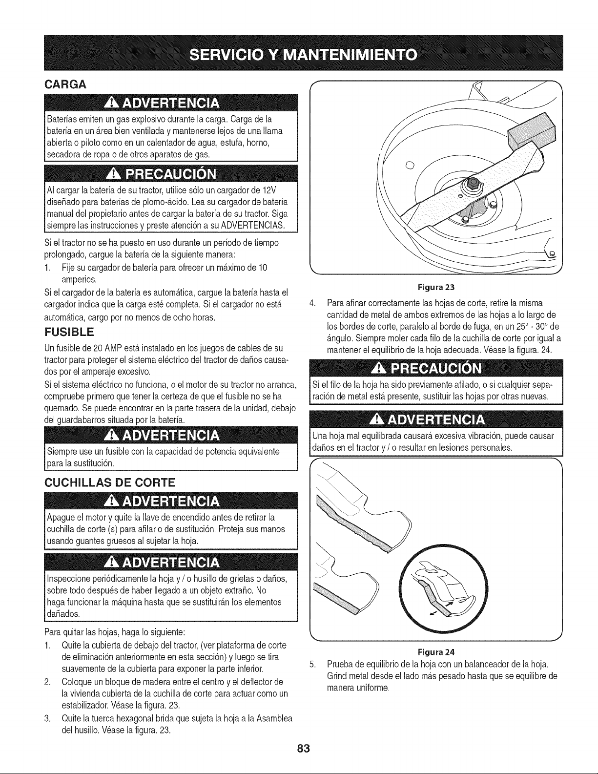
CARGA
Bateriasemiten ungasexplosivodurantelacarga.Cargade la
bateriaen un _.reabienventiladay mantenerselejos deunallama
abiertao pilotocomo en uncalentadordeagua,estufa,homo,
secadorade ropao de otrosaparatosde gas.
AIcargarla bateriadesu tractor,utilices61ouncargadorde 12V
dise_adopara bateriasde plomo-_.cido.Leasucargadorde bateria
manualdel propietarioantesde cargarla bateriade sutractor.Siga
siemprelas instruccionesy presteatenci6na su ADVERTENCIAS.
Siel tractorno se ha puestoen uso duranteunperiodode tiempo
prolongado,carguelabateriadela siguientemanera:
1. Fijesu cargadorde bateriapara ofrecerun m_.ximode 10
amperios.
Siel cargadorde la bateriaes autom_.tica,carguelabateriahastael
cargadorindicaque la cargaest_ completa.Siel cargadornoest,.
autom_.tica,cargoporno menosdeocho horas.
FUSIBLE
Unfusiblede20 AMPest,. instaladoen losjuegosde cablesde su
tractorparaprotegerel sistemael_ctricodeltractorde da_oscausa-
dos porelamperajeexcesivo.
Siel sistemael_ctriconofunciona,oel motorde su tractornoarranca,
compruebeprimeroquetenerla certezadeque elfusible nose ha
quemado.Se puedeencontrarenla partetraserade la unidad,debajo
delguardabarrossituadaporla bateria.
Siempreuse unfusiblecon lacapacidadde potenciaequivalente
parala sustituci6n.
CUCHILLAS DE CORTE
Apagueel motory quitela Ilavede encendidoantesde retirarla
cuchilladecorte (s) paraafilaro de sustituci6n.Protejasus manos
usandoguantesgruesosal sujetarla hoja.
Inspeccioneperi6dicamentelahoja y / o husillode grietaso da_os,
sobretododespu_sdehaber Ilegadoa un objetoextra_o.No
hagafuncionarla m_.quinahastaque se sustituir_.nlos elementos
da_ados.
Paraquitarlas hojas,hagaIo siguiente:
1. Quitela cubiertadedebajodel tractor,(ver plataformadecorte
deeliminaci6nanteriormenteenesta secci6n)y luego se tira
suavementedela cubiertapara exponerla parteinferior.
2. Coloqueun bloquede maderaentreel centroy el deflectorde
la viviendacubiertade la cuchillade corteparaactuarcomo un
estabilizador.Wase la figura.23.
3. Quitela tuercahexagonalbridaquesujetala hoja a laAsamblea
delhusillo.Wase la figura.23.
Figura 23
Paraafinarcorrectamentelas hojasdecorte, retirela misma
cantidadde metaldeambosextremosde las hojasa Io largode
losbordesdecorte,paraleloal hordede fuga,en un 250. 300de
_.ngulo.Siempreraciercadafilo de la cuchilladecortepor iguala
mantenerel equilibriode la hoja adecuada.Wase la figura.24.
Si el filode la hojahasido previamenteafilado,o si cualquiersepa-
raci6nde metalest,. presente,sustituirlas hojaspor otrasnuevas.
Unahojarealequilibradacausar_,excesivavibraci6n,puedecausar
daSosen el tractory / o resultaren lesionespersonales.
Figura24
Pruebade equilibriode la hojacon un balanceadorde lahoja.
Grindmetaldesdeel ladom_.spesadohastaquese equilibrede
manerauniforme.
83
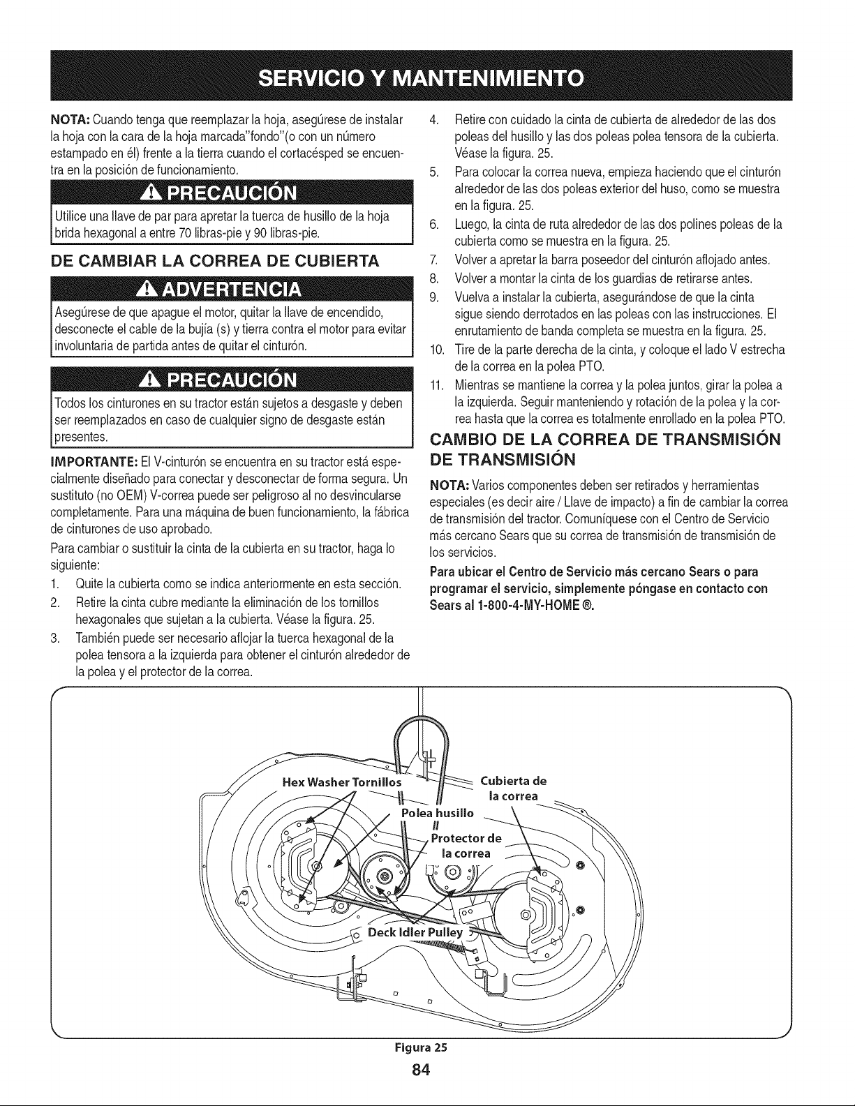
NOTA: Cuandotengaque reernplazarla hoja,aseg[3resede instalar
la hojacon la carade la hojarnarcada"fondo"(ocon un nQrnero
estarnpadoen_1)frentea la tierracuandoelcortacespedse encuen-
tra enla posici6ndefuncionarniento.
UtiliceunaNavede par paraapretarlatuercade husillodela hoja
bridahexagonala entre70 libras-piey 90 Nbras-pie.
DE CAIVlBIAR LA CORREA DE CUBIERTA
Aseg_resede queapagueel motor,quitarla Navede encendido,
desconecteel cablede la bujfa(s) y tierracontrael motor paraevitar
involuntariade partidaantesdequitarel cintur6n.
Todosloscinturonesen su tractorest_.nsujetosadesgastey deben
Iser reernplazadosencasode cualquiersignodedesgasteest_.n
presentes.
4. Retirecon cuidadolacinta de cubiertade alrededorde las dos
poleasdel husiNoy lasdos poleaspoleatensorade lacubierta.
Wase lafigura.25.
5. Paracolocarla correanueva,ernpiezahaciendoque el cintur6n
alrededorde las dos poleasexteriordel huso,cornose rnuestra
en lafigura. 25.
6. Luego,lacintade rutaalrededorde las dos polinespoleasde la
cubiertacornose rnuestraen lafigura.25.
7. Volvera apretarla barraposeedordelcintur6naflojadoantes.
8. Volvera rnontarla cinta de losguardiasde retirarseantes.
9. Vuelvaa instalarla cubierta,asegur_.ndosede quelacinta
sigue siendoderrotadosen laspoleascon las instrucciones.El
enrutarnientodebanda cornpletase rnuestraen la figura.25.
10. Tire de la partederechade la cinta,y coloqueel lado V estrecha
de lacorreaen lapolea PTO.
11. Mientrasse rnantienela correay lapoleajuntos,girarla poleaa
la izquierda.Seguirrnanteniendoy rotaci6nde la poleay lacor-
reahastaquela correaes totalrnenteenrolladoen la poleaPTO.
IMPORTANTE: El Vicintur6nse encuentraensu tractorest,.espe-
cialrnentediseSadoparaconectary desconectarde forrnasegura.Un
sustituto(no OEM)Vicorreapuedeserpeligrosoal nodesvincularse
cornpletarnente.Paraunarn_.quinade buenfuncionarniento,la f_.brica
decinturonesdeuso aprobado.
Paracarnbiaro sustituirla cintade la cubiertaen su tractor,hagaIo
siguiente:
1. Quitelacubiertacornose indicaanteriorrnenteen esta secci6n.
2. Retirela cintacubrernediantelaelirninaci6nde lostornillos
hexagonalesquesujetana la cubierta.Wase la figura.25.
3. Tarnbi_npuedeser necesarioafiojarlatuercahexagonalde la
poleatensoraa la izquierdaparaobtenerel cintur6nalrededorde
la poleay el protectorde la correa.
CAIVlBIO DE LA CORREA DE TRANSiVlISI6N
DE TRANSiVllSI6N
NOTA: Varioscornponentesdebenser retiradosy herrarnientas
especiales(es deciraire/ Llavede irnpacto)a fin decarnbiarlacorrea
de transrnisi6ndel tractor.Cornunfquesecon elCentrode Servicio
rn_.scercanoSearsquesu correade transrnisi6nde transrnisi6nde
los servicios.
Paraubicarel Centro de Servicio m_scercanoSears o para
programarel servicio, simplementep6ngaseen contactocon
Sears al 1-800-4-MY-HOME®.
Cubierta de
la correa
Figura 25
84
Nuncaalmacenetractorde cespedconcombustibleen el tanque
en unespaciocerradoo en _.reasconpoca venfilaci6n,dondelos
gasesdel combustiblepuedanalcanzarel fuego,chispaso unaluz
pilotocomola quetienenalgunoshornos,calentadoresde agua,
secadoresde ropao algQnotto disposifivoa gas.
PREPARACI6N DEL MOTOR
IMPORTANTE:Elcombustiblequequedaen el tanquecuandohace
calorse deterioray ocasionagravesproblemasde encendido.
Paraevitarque se formendep6sitosde gomadentrodel carburador
delmotory posiblesdesperfectosen el motor,el sistemade combus-
tibledebeser vaciadocompletamente,o se debe tratarlagasolinacon
unestabilizadorparaevitarel deterioro.
1. Si ufilizaunestabilizadordecombustible:
a. Lealas instrucdonesy recomendadonesdel fabricantedel
producto.
b. Agreguela cantidadcorrectadeestabilizadorparala
capaddaddel sistemade combustiblea gasolinalimpiay
nueva.
c. Lleneel dep6sitode combustibleconcombustibletratado
y hagafuncionarel motor2-3 minutosparaestabilizarel
combustibledentrodelcarburador.
4. Cuandovacie el sistemade combustible:
a. Nodreneel combustiblecuandoel motorest,. caliente.
Permitaque el motorse enfrie bien.Dreneel combustible
dentrode un recipienteaprobadoy al airelibre,lejosde
cualquierllamaexpuesta.
b. Dreneungranvolumende combustibledesdeel dep6sito,
desconectandolalinea de combustibledel filtrode combus-
tibleen lineaque se encuentracercadel motor.
c. Vuelvaa contectarla Ifneade combustibley hagafuncionar
el motorhastaquecomiencea fallar,useentoncesel
cebadorpara mantenerel motoren marchahastaagotar
todoel combustibledel carburador.
d. Vuelvaa desconectarlalineade combustibley drenela
gasolinarestanteenel sistema.
5. Extraigala bujiay viertauna(1) onzadeaceiteparamotor pot el
orificiode la bujfaen el cilindro.Hagagirarel motorvariasveces
paradistribuirel aceite.Vuelvaa colocarla bujfa.
Lagasolinaessumamenteinflamabley puedesetexplosivaenciertas
condiciones.Vacfelaantesde aimacenarei equipoduranteperiodos
prolongados.Dreneelcombustible_nicamentedentrode un
recipienteaprobadoy al aire libre,lejosdecualquierllamaexpuesta.
Dejeque el motorseenfrie.Antesde drenarel combustible,apague
cigarrillos,cigarros,pipasy otrasfuentesde combusti6n.Vacfela
gasolinaenuna.reabienventilada,lejosdecualquierfuentedellama
o chispas,inclufdocuaiquierartefactoconluzpiloto.AImacenela
gasolinaenunrecipienteaprobado,en unlugarseguro.
EL DRENAJE DE LOS COMBUSTIBLES
1. Localiceel filtro decombustible,que seencuentraen el lado
izquierdodel motor,y puedeserconectadoal motorcon una
correade empate.
2. Cortarla correade la corbata,si est,.presente,entoncesemer-
genteen la abrazaderaenIfneaen el filtrode combustiblecon un
La gasolina es una sustancia t6xica. Elimineia gasolina
adecuadamente. Comuniquese con las autoridades locales para
averiguar cua.iesson los metodos adecuados paraeliminar la gasolina.
pardealicates,deslicelaabrazaderadela Ifneadecombustible.
3. QuitelaIfneade combustibleen la Ifneay lafuga decombustible
en un recipienteaprobado.
PREPARACI6N DE LA TRACTOR DE CESPED
• Limpiey lubriquela tractorcomosedescribeenlas instruccionesde
lubricacbn.
• Noutiliceuna lavadoraa presi6nni unamangueradejardfnpara
limpiarsu unidad.
• Almacenela tractoren unazonalimpiay seca.Nolaalmacenecerca
de materialescorrosivoscomoporejemplofertilizantes.
85
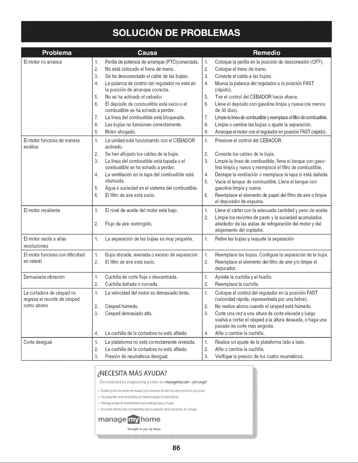
Elmotorno arranca
Elmotorfuncionade manera
err_tica
1. Perillade potenciade arranque(PTO)conectada.
2. No est&colocadoelfreno de mano.
3. Se ha desconectadoel cablede lasbujias.
4. La palancade controldel reguladorno est_en
la posici6nde arranquecorrecta.
5. No se ha activadoel cebador
6. El dep6sitode combustibleest_ vacio o el
combustiblese ha echadoa perder.
7. La linea del combustibleest&bloqueada.
8. Las bujias nofuncionan correctamente.
9. Motorahogado.
1. La unidad est_funcionandocon el CEBADOR
activado.
2. Se hanaflojado loscables de la bujia.
3. La linea del combustibleest_tapada o el
combustiblese ha echadoa perder.
4. La ventilaci6nen la tapadel combustibleest_
obstruida.
5. Aguao suciedaden el sistemadel combustible.
6. EIfiltro de aireest_ sucio.
1. Coloque la perillaen la posici6nde desconexi6n(OFF).
2. Coloque elfreno de mano.
3. Conecte elcable a las bujias.
4. Muevala palancadel reguladora la posici6nFAST
(r@ido).
5. Tire el controldel CEBADORhacia afuera.
6. Lleneel dep6sitocongasolina limpiay nueva(de menos
de 30dias).
7. Limpielalineadecombustibley reemplaceelfiltrodecombustible.
8. Limpieo cambie las bujiaso ajustela separaci6n.
9. Arranqueelmotorconelreguladoren posici6nFAST(r@ido).
1. Presioneel control del CEBADOR.
2,
3.
4,
5.
6,
Elmotorrecalienta 1. El nivel de aceitedel motorest_ bajo. 1.
2.
2. Flujodeairerestringido.
Elmotorvacila a altas 1. La separaci6nde lasbujias es muy pequeSa. 1.
revoluciones
Elmotorfuncionacon dificultad 1. Bujiaatorada,averiadao excesode separaci6n. 1.
en ralenti 2. El filtrode aireest_ sucio. 2.
Demasiadavibraci6n 1. Cuchillade cortefloja o descentrada. 1.
2. CuchilladaSadaocurvada 2.
1. La velocidaddel motores demasiadolenta. 1.
2. Cespedh0medo.
3. Cespeddemasiadoalto.
La cortadorade cespedno
regresael recortede cesped
comoabono
4,
1.
2.
3.
La cuchillade lacortadora no est_afilada.
Cortedesigual La plataformano est&correctamentenivelada.
La cuchillade lacortadora no est_afilada.
Presi6nde neum_ticosdesigual.
Conecte loscables de la bujia.
Limpiela linea de combustible;Ileneeltanquecon gaso-
lina limpiay nuevay reemplaceelfiltro decombustible.
Destapelaventilaci6no reemplacela tapa si est&daSada.
Vacie el tanquede combustible.Lleneel tanquecon
gasolina limpiay nueva.
Reemplaceelelementode papeldel filtrode aireo limpie
el depuradorde espuma.
Lleneel cartercon laadecuadacantidady pesode aceite.
Limpielos recortesde pastoy la suciedadacumulados
alrededorde lasaletasde refrigeraci6ndel motory del
alojamientodel soplador.
Retirelasbujias y reajustelaseparaci6n
Reemplacelas bujias.Configurela separaci6nde la bujia.
Reemplaceelelementodel filtro de airey/o limpie el
depurador.
Apriete lacuchillay el husillo.
Reemplacelacuchilla.
Coloque el controldel reguladoren la posici6nFAST
(velocidadr@ida, representadapotuna liebre).
2. Norealiceabonocuando el cespedest& h0medo.
3. Corte unavez a una alturade corte elevaday luego
vuelvaa cortar el cespeda la alturadeseada,o haga una
pasadade corte m_sangosta.
4. Afile ocambie la cuchilla.
1. Realiceun ajustede laplataformaladoa lado.
2. Afile ocambie la cuchilla.
3. Verifiquela presi6nde los cuatroneum_ticos.
_NECESITA MAS AYUDA?
[:'nconvrar_ b._ix:! pue vay mi_ en managemy.com-isin cargo.' i
, Enlrlleapodr_encon_rarestemanualylosmanualesdetodosloso_rosproductosqueposea [
Suspreguntasser4nrespondidaspornuestroequbodeespedalistas i/
Obter/gaun plandemarl_enimientopersonalizadoparasuhogar
Encuer/treinfoHlladOr,y herramientasqueIoayudar4nconlosproyec_osdesuhogar
manage _ home I
86
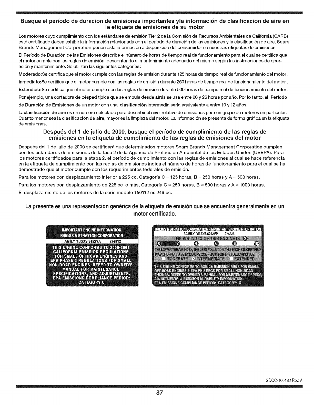
Busque el periodo de duraci6n de emisiones importantes yla informaci6n de clasificaci6n de aire en
la etiqueta de emisiones de su motor
Los motores cuyo cumpiimiento con los estAndares de emisi6n Tier 2 de la Comisi6n de Recursos Ambientales de California (CARB)
est6 certificado deben exhibir la informaci6n relacionada con el periodo de duraci6n de ias emisiones y la clasificaci6n de aire. Sears
Brands Management Corporation ponen esta informaci6n a disposici6n del consumidor en nuestras etiquetas de emisiones.
Ei Periodo de Duraci6n de las Emisiones describe el nQmero de horas de tiempo real de funcionamiento para el cuai se certifica que
el motor cumpie con ias reglas de emisi6n, descontando el mantenimiento adecuado del mismo segQn las instrucciones de oper-
aci6n y mantenimiento. Se utilizan las siguientes categonas:
Moderado:Se certifica que el motor cumpie con las reglas de emisi6n durante 125 horas de tiempo real de funcionamiento del motor.
Inmediato:Se certifica que el motor cumpie con las reglas de emisi6n durante 250 horas de tiempo real de funcionamiento del motor.
Extendido:Se certifica que el motor cumpie con las reglas de emisi6n durante 500 horas de tiempo real de funcionamiento del motor.
Por ejemplo, una cortadora de c6sped tJpica que se empuja desde arras se usa entre 20 y 25 horas por aSo. Por Io tanto, el Periodo
de Duraci6n de Emisiones de un motor con una clasificaci6n intermedia sena equivaiente a entre 10 y 12 aSos.
Laciasificaci6n de aire es un nQmero calculado para describir el nivel relativo de emisiones para un grupo de motores en particular.
Cuanto menor sea la clasificaci6n de aire, mayor es la limpieza del motor. La informaci6n se presenta de forma grAfica en la etiqueta
de emisiones.
Despu_s del 1 de julio de 2000, busque el periodo de cumplimiento de las reglas de
emisiones en la etiqueta de cumplimiento de las reglas de emisiones del motor
Despu6s del 1 de julio de 2000 se certificarA que determinados motores Sears Brands Management Corporation cumplen
con los estAndares de emisiones de la fase 2 de la Agencia de Protecci6n Ambientai de los Estados Unidos (USEPA). Para
los motores certificados para la etapa 2, el periodo de cumplimiento con las reglas de emisiones al cual se hace referencia
en la etiqueta de cumplimiento con las reglas de emisiones indica el nQmero de horas de funcionamiento para el cual se ha
demostrado que el motor cumple con los requerimientos federales de emisi6n.
Para los motores con desplazamiento inferior a 225 cc, Categoria C = 125 horas, B = 250 horas y A = 500 horas.
Para los motores con desplazamiento de 225 cc o mAs, Categoria C = 250 horas, B = 500 horas y A = 1000 horas.
El desplazamiento de los motores de la serie modelo 150112 es 249 cc.
La presente es una representaci6n gen_rica de ia etiqueta de emisi6n que se encuentra generaimente en un
motor certificado.
FAMILYYBSXS.3192VA 274812
GDOC-100182Rev.A
87
(Esta p_.ginase aplica s61oen EE.UU. y Canada.).
Sears Brands Management Corporation, el Consejo de Recursos Ambientales de California (CARB)
y la Agencia de Protecci6n Ambiental de los Estados Unidos (EPA)
Declaraci6n de garantia del sistema de control de emisiones (derechos y obligaciones de la garanfia de defectos del propi=
etario)
LA COBERTURADE LA GARANTJADE CONTROLDEEMISIONESES Y PARALOSMODELOSCERTIFICADOSDELANO 1997YPOSTERIORES,
APLIOABLEA LOSMOTORESCERTIFICADOSCOMPRADOSENCALIFOR- QUESE COMPRENY UTILICENENCUALQUIERPARTEDE LOS ESTADOS
NIA EN1995Y POSTERIORMENTE,QUESE UTILIZANENCALIFORNIA, UNIDOS(Y A PARTIRDEL 1 DE ENERODE2001 EN CANADA).
Declaraci6n de garanfia sobre defectos en el control de emJsiones para California y los Estados UnJdos
ElConsejode RecursosAmbientalesde California(CARB),la EPA(Agencia
de Protecci6nAmbientalde los EE.UU.)y Searstienenel gusto de explicarla
garantiadel sistemade control de emisionespara motoresdela_o 2000y para
elfuturo con relaci6na motorespeque_ostodo terreno(SORE).En California,
los nuevosmotorespeque_ostodo terrenodebenestar dise_ados,construidos
y equipadosparacumplirconlas rigurosasnormasanti-smogdelestado.En
el restodelos EstadosUnidos,losmotoresnuevostodo terrenode encendido
porchispacertificadosparael a_o 1997debencumplirest_ndaressimilares
establecidospot la EPA.Sears debegarantizarel sistemade control de emi-
sionesde su motorpara losperiodosde tiempoenumeradosa continuaci6n,
siemprequeno hayaabuso,negligenciao mantenimientoindebidode su
motortodoterrenopeque_o.Su sistemade controlde emisionespuedeincluir
piezastalescomoel carburador,el filtro de aire, elsistemade encendido,el
silenciadoryel conversorcatalitico.Tambienpuedeincluirconectoresy otras
unidadesrelacionadascon lasemisiones.Dondeexistaunacondici6ncubierta
por la garantia,Searsreparar_su peque6omotortodo terrenosin costoalguno
incluyendodiagn6stico,piezasy manodeobra
Cobertura de la garantJa Sears para defectos en el control de emJsiones
Los motorestodo terrenopeque6osest_ngarantizadosen Io relativoalcontrol alas disposicionesque se indiquena continuaci6n.Si una partede su motor
de emisionesparadefectosen piezasduranteun periodode dosa_os,sujeto cubiertapot la garanfiaes defectuosa,Sears reparar_o sustituir_dichaparte.
Responsabilidades del propietario en relacibn con la garantia
Comopropietariodel motortodo terrenopeque_o,Ud.es responsablede la
realizaci6ndel mantenimientorequeridoquese incluyeen las instrucciones
de operaci6ny mantenimiento.Searsrecomiendaquese conserventodoslos
recibosrelativosal mantenimientode su motortodoterrenopeque_o,pero
no pude denegarla garantiasimplementepor la faltade los mismos,o por su
incumplimientodel mantenimientoprogramatic.Comopropietariodel motor
peque_otodoterrenodebe saberque, sinembargo,Sears lepuedenegar
lacoberturade lagarantiasi su motortodoterrenopeque6oouna piezadel
mismohanfalladodebido a abuso,negligencia,mantenimientoindebidoo
a modificacionesno aprobadas.Ud.es responsablede presentarsu motor
todoterrenopeque6oa un distribuidorde serviciosSearsautorizadotan pronto
comoaparezcaun problema.Las reparacionesde la garantiasinconfiicto
debencompletarseen un plazode tiempo razonable,no superiora 30 dias.Si
tienealguna preguntarespectoa sus derechosy responsabilidadesreferentes
a lagarantia,debe contactarcon un representantede serviciosSears al 1--
800--469--4663.La garantiade emisioneses una garantiapot defectos.Los
defectosse juzgande acuerdocon elfuncionamientonormalde un motor.La
garantiano est_relacionadacon unapruebade emisionesen uso.
Disposiciones de la garantJa Sears para defectos en el control de emJsiones
Las siguientesson disposicionesespecificasrelacionadascon la coberturade lagarantia paradefectosenel controldeemisiones.Esun a_adidoa lagarantiade
motorSearspara motoresno reguladosquese encuentraen lasinstruccionesde funcionamientoy mantenimiento.
1. Piezascon garantia
La coberturade esta garantiase extiendeL]nicamentealas piezas
queaparecena continuaci6n(las partesde lossistemasde controlde
emisiones),siempreque dichaspiezasestuvieranya en el motoren el
momentode su compra.
a. Sistemademedici6n de combustible
• Sistemade enriquecimientopara arranqueen frio
• Carburadory partesinternas
• Bombade combustible
b. Sistemadeinducci6nde aire
• Filtrode aire
• Colector de admisi6n
c. Sistemadeencendido
• Bujia(s)de encendido
• Sistemade encendidomagneto
d. Sistemadelcatalizador
• Convertidorcatalitico
• Colector de escape
• Sistemade inyecci6nde aireo v_lvulade impulsos
e. Elementosvariadosusadosenlossistemasanteriores
• Wlvulas de vacio,sensiblesa temperatura,posici6ny tiempo
e interruptores
• Conectoresy montajes
2. AIcancede la cobertura
Searsgarantizaal poseedorinicialy a los compradoressubsiguientes
quelas piezascon garantiano tendr_n defectosen materialesni mano
de obraque provoquenla falla de las mismasduranteun periodode
dos aSosa partirde la fechaen queel motorse entregaa un comprador
particular.
3. Sincargo
La reparaci6no reemplazode cualquierpartecon garantia se realizar_
sin cargo algunoparael poseedor,incluyendotareasde diagn6sticoque
permitandeterminarsi una partecon garantiaes defectuosa,siempreque
dichodiagn6sticose realiceen un distribuidorde serviciosSears autoriza-
do. Parael servicio de lagarantiade emisiones,contacteal distribuidorde
serviciosSearsautorizadom_s cercanoincluidoen las"P_ginasamarillas"
en lascategorias"Motores,gasolina","Motoresde gasolina","Podadoras
de cesped",o similares.
4. Reclamacionesyexclusionesa la cobertura
Las reclamacionesde lagarantia debenenviarsedeacuerdocon las
disposicionesde la politica de garantia para motoresSears.La cobertura
de lagarantia excluir_defectosen piezascongarantia queno sean partes
originalesSears,o abuso,negligenciao mantenimientoincorrecto,tal y
como seestableceen lapolitica de garantia para motoresSears.Searsno
es responsablede lasfallas en piezascon garantia provocadaspor el uso
de partesa_adidas,que no seanoriginaleso quese hayan modificado.
5. Mantenimiento
Cualquierpartecon garantiaque no este programadaparaset reempla-
zadacomo mantenimientorequerido,o ques61odeba inspeccionarse
regularmentealefecto de "inspeccioneo reemplacesegL]nsea necesario",
estar_garantizadacontradefectosduranteel periodode lagarantia. Todas
las piezasgarantizadasqueesten programadaspara su reemplazopara
cumplir con los requisitosde mantenimientoestar_ngarantizadass61o
por el periodoanterioral primerreemplazoprogramaticparadicha pieza.
Cualquierpiezade recambioquesea equivalenteen funcionamientoy
durabilidadpuedeusarse para realizarmantenimientoo reparaciones.El
propietarioes responsablede realizartodoel mantenimientorequerido,tal
y comose define en las instruccionesde funcionamientoy mantenimiento
Sears
6. Coberturaindirecta
Porla presente,la coberturase extiendea la falla de cualquiercomponente
de motorprovocadapot lafalla de unapieza con garantiaque estetodavia
en periodode garantia.
En los EstadosUnidosy Canad_hay unalinea de atenci6nde24 horas,1-800-469--4GG3,quecuentacon un menL]con mensajespre-grabadosque contienen
informaci6npara el mantenimientode motores.
DECLARACIONFEDERALy/oDECALIFORNIASOBRE GARANTJAS EN EL CONTROL DE EIVIISIONES
SUS DERECHOS Y OBLIGACIONES EN CUANTO A LA GARANTJA
MTDConsumerGroupInc, laAgencia de Protecci6nMedioambientaldelos EstadosUnidos(EPA),y paraaquellosproductoscertificadosparasu ventaen el es-
tadode California,el Departamentode los Recursosdel Aire de California(CARB)secomplacenen explicarla garanfiaque cubre al sistemade control (ECS)de
emisiones(evaporativasy/o de escape)de su equipoy motor(motorde equipos de exteriores)de encendidopot chispaparatodo terreno,peque_o,deexteriores
del a_o2006 y a_osposterioresEn California,losnuevosmotoresde equipos de exterioresdebenestar dise_ados,construidosy equipadospara cumplircon las
estrictasnormasantipoluci6ndel Estado(en otrosestados,los equiposdel a_o 1997y modelosposterioresdebenser estar dise_ados,construidosy equipados
para cumplircon las regulacionesde motoresde encendidopor chispapara todoterrenopeque_osde laAgencia de Protecci6nMedioambientalde los Estados
Unidos,(EPA).MTDConsumerGroupInc. debe garantizarel sistemade controlde emisiones(ECS) de su motorde equipos de exteriorespot el periodode
tiempo indicadom_sabajo,siempreycuando no existausoincorrecto,negligenciao mantenimientoinadecuadode dicho motor.
Su ECSpuedeincluir piezastales como el carburador,el sistemade inyecci6nde combustible,el sistemade encendido,el convertidorcatalitico,losdep6sitos
de combustible,laslineas de combustible,lostaponesde combustible,lasv_lvulas, contenedores,filtros, manguerasde vapor,abrazaderas,conectoresyotros
componentesafinesrelacionadoscon lasemisiones.
Dondeexista unacondici6ncubiertapor la garantia,MTDConsumerGroupInc. reparar_su motorde equiposde exterioressincostoalguno incluyendoel
diagn6stico,las piezasy la mano de obra.
COBERTURA DE LA GARANTJA DEL FABRICANTE:
Este sistemade control de emisionesse garantizaporel t@minode dos aSos.Si algunapiezarelacionadacon lasemisionesde su motorde equiposde
exterioreses defectuosa,MTDCONSUMERGROUPINC.reparar_o sustituir_dichapieza.
RESPONSABILIDADES DEL PROPIETARIO SEGUN LA GARANTJA:
En su car_cterde propietariodel motorde equipos de exteriores,usted es responsabledel mantenimientorequeridoquese especificaen el manualdel propieta-
rio.MTDConsumerGroupInc le recomiendaque conservetodos losrecibos quecubrenel mantenimientode su motor,no obstanteIo cual MTDConsumerGroup
Inc no podr_denegarel cumplimientode lagarantia Qnicamentepor lafaltade los recibos.
Comopropietariodel motorde equiposde exteriores,usteddebe saber queMTDConsumerGroupInc. puededenegarlacoberturade lagarantia si su motoro
unapieza del mismofallan debidoa uso incorrecto,negligencia,mantenimientoindebido o a modificacionesno aprobadas.
Ustedes responsablede presentarsu motoral centrode distribuci6no serviciotecnico de MTDConsumerGroupInc. tan prontocomo aparezcael problema.Las
reparacionescubiertaspor la garantiase debenIlevara caboen un lapsorazonableque no excedade30 dias. Sitiene alguna preguntarespectode lacobertura
de la garantia,p6ngaseen contactoconel Departamentodel ServicioT@nicode MTDConsumerGroupInc. al telefono1-800-800-7310o pot correoelectr6nico
en http://support.mtdproducts.com
COBERTURA DE LA GARANTJA DE EMISIONES GENERALES:
MTDConsumerGroupIncgarantizaal compradorfinal y a cadacompradorsubsiguienteque el motordeequiposde exteriores:est_ dise_ado,construidoy
equipadode modo de cumplir contodas las regulacionesaplicablesy quese encuentralibre de defectosde materialesyde fabricaci6nque pudierencausar la
falla de una piezagarantizadaidentica,en todos losaspectos materialesa la pieza descriptaen la solicitudde certificaci6nde MTDConsumerGroupInc.
El periodode garantiacomienzaen la fechade entregadel motoral compradorfinal o en lafecha en que la m_quinase pone en funcionamientopot primeravez.
El periodode garantiaes de dos aSos.
Sujetoa ciertas condicionesyexclusionesquese indicana continuaci6n,lagarantia de las piezas relacionadascon lasemisioneses la siguiente:
1. Cualquierpiezagarantizadaque no esteprogramadaparaser reemplazadacomo partedel mantenimientorequeridoen lasinstruccionesescritassuminis-
tradasse garantizaporel periodo de garantiaarriba mencionado.Sila piezafalla duranteel periodo de coberturade lagarantia, la mismaser_reparada
o reemplazadapor MTDConsumerGroupInc. de acuerdo con el parrafo(4) a continuaci6n.Cualquierpiezareparadao reemplazadasegQnlagaranfia se
garantizar_potel resto del periodode garantia.
2. Cualquierpiezagarantizadaqueeste programadasolamenteparainspecci6nregularen las instruccionesescritassuministradassegarantiza potel periodo
de garantia arribamencionado.Cualquierpiezareparadao reemplazadasegQnla garantiase garantizar_pot el restodel periodo.
3. Cualquierpiezagarantizadaqueeste programadapara reemplazosegQnel mantenimientorequeridode conformidadcon lasinstruccionesescritassuminis-
tradas,se garantizaporel periododetiempo anteriora la primerafecha de reemplazoprogramadapara esa pieza.Si la piezafalla antes del primerreemplazo
programado,la mismaser_ reparadao reemplazadapot MTDConsumerGroupInc. de acuerdo con el parrafo(4) a continuaci6n.Cualquierpiezareparadao
reemplazadabajogarantia se garantizar_pot el resto del periodoanterioral primerreemplazoprogramaticpuntualpara esa pieza.
4. La reparaci6no el reemplazodecualquierpiezagarantizadade conformidadcon lasdisposicionesde lagarantia queaquise estipulase deben realizaren un
centrode garantiasin costo algunopara el propietario.
5. Noobstantelas disposicionesque aqui se estipulan,losservicios o reparacionesbajo garantiase suministrar_nen todos nuestroscentrosde distribuci6nbajo
franquiciademantenimientoparalos motoreso equiposen cuesti6n.
6. El propietariodel motorde equiposde exterioresno deber_pagarel trabajode diagn6sticodirectamenteasociadocon unapiezagarantizadadefectuosaen
relaci6ncon las emisiones,siempreycuandodicho trabajode diagn6sticose realiceen un centrocubiertopot lagarantia.
7. MTDConsumerGroupInces responsablepotda6os causadosa otros componentesde motoreso equipos derivadosde lafalla bajo garantiade cualquier
piezagarantizada.
8. Durantelatotalidaddelperiododegarantiadelmotoryequipoparatodoterrenoarribamencionado,MTDConsumerGroupIncmantendr_unsuministro
depiezasbajogarantiasuficienteparasatisfacerlademandaesperadadetalespiezas.
9. Cualquierpiezadereemplazosepodr_usarparaelcumplimientodelmantenimientoolasreparacionesbajogarantiaysesuministrar_nsincargopara
elpropietario.Dichousonoreducir_lasobligacionesdegarantiadeMTDConsumerGroupInc.
10.Nosepodr_nusarpiezasadicionalesnimodificadasquenoestenexentasdeacuerdoconelDepartamentodelosRecursosdelAire(AirResourcesBoard).
Elusodecualquierpiezaadicionalomodificadanoexentaporelcompradorfinalser_causaldeinvalidezdelosreclamosbajogaranfia.MTDConsumer
GroupIncnotendr_responsabilidadpotlagarantiadefallasdepiezasgarantizadasquefuerencausadaspotelusodeunapiezaadicionalnoexenta
omodificada.
PIEZAS GARANTIZADAS:
La reparaci6no el reemplazodecualquierpiezagarantizadaquede otto modo pudieseestar cubiertapot lagarantia podr_set excluidade tal coberturade
garantiasi MTDConsumerGroupIncdemuestraqueel motores objeto de uso incorrecto,negligenciao mantenimientoinadecuado,y que tal uso incorrecto,
negligenciao mantenimientoinadecuadofue causadirectade la necesidadde reparaci6no reemplazode dichapieza.NoobstanteIo antedicho,cualquierajuste
de un componentecon un dispositivode limitaci6nde ajusteinstaladoen f_brica y quefuncioneadecuadamente,podr_set cubiertopot la garantia.Adem_s,
la coberturabajoesta garantiase extiendesolo a piezasqueestuvieronpresentesen el motory equipotodo terrenoadquiridos.
Est_ncubiertaslas siguientespiezascon garanfia para emisiones(decorresponder):
(1) Sistemade medici6nde combustible
• Sistemade mejorapara inicioen frio (cebadosuave)
• Carburadory piezasinternas(o sistemade inyecci6npotcombustible)
• Bombade combustible
• Dep6sitode combustible
(2) Sistemade inducci6ndeaire
• Purificadordeaire
• Colectordeadmisi6n
(3) Sistemade encendido
• Bujia(s) deencendido
• Sistemade encendidopot magneto
(4) Sistemade encendido
• Convertidorcatalitico
• SAl(v_lvula Reed)
(5) Componentesvariosutilizadosen el sistemaanterior
• Wlvulas e interruptoresde vacio,temperatura,posici6nsensiblesal tiempo
• Conectoresy montajes
(6) Controlevaporativo
• Manguerade combustible
• Abrazaderasde la manguerade combustible
• Tap6ndel combustibleatadopot correa
• Cajadecarbono
• Lineas de vapor
GDOC-100223
Felicitacionespor haberrealizadounaadquisici6ninteligente.El
productoCraftsman@queha adquiridoest_dise_adoy fabricado
parabrindarrnuchosa_osde funcionarnientoconfiable.Perocorno
todoslos productosa vecespuederequerirde reparaciones.Esen
esernornentocuandoel disponerde unAcuerdode protecci6npara
reparacionesle puedeahorrardineroy problernas.
A continuaci6nsedetallanlos puntosincluidosenel Acuerdo:
• Servicio experto prestadopornuestros10,000especialistasen
reparacionesprofesionales
• Servicio ilirnitadosincargoparalaspiezasy la rnanode obraen
todaslas reparacionescubiertas
• Reemplazodel productohasta1500d61aressi no es posible
repararel productocubierto
• Descuentode 10%del precionormaldel servicioy de las piezas
relacionadascon el rnisrnoque no est_ncubiertaspor el acuerdo;
adern&s,10%del precionormalde laverificaci6nde rnantenirniento
preventivo
• Ayudar_pida pot tel_fono- IoIlarnarnosResoluci6nR_.pida- el
apoyotelef6nicode unCharnuscaal representante.Pienseen
nosotroscornoel manual"de un due_ohablador."
Unavezadquiridoel Acuerdo,puedeprograrnarel serviciocon
tan s61orealizarunaIlarnadatelef6nica.PuedeIlarnaren cualquier
mornentodeldia o de la nocheo prograrnarun servicioen linea.
ElAcuerdode Protecci6nde Reparaci6nes una cornprasin riesgo.
Siustedanulaporalgunaraz6nduranteel periodode garantiade
producto,proporcionarernosun reernbolsoIleno.O,un reernbolso
prorrateadoen cualquierrnornentodespu_sdel periodode garantia
de productoexpira, iAdquieraboysu acuerdode protecci6npara
reparaciones!
Se aplican determinadas limitaciones y exclusiones. Para obtener
informaci6n adicional y precios en los Estados Unidos Ilame al
1-800-827-6655.
El *Coverage en Canad;_varia en algunos articulos. Para detalles
Ilenos la Ilamada Chamusca Canad_ en 1-800-361-6665.
Servicio de instalaci6nde Sears
Sideseasolicitarla instalaci6nprofesionalde Searsde aparatos
dorn_sticos,dispositivosparaabrirportones,calentadoresde agua
y otrosarficulosdorn_sticosirnportantes,en los EstadosUnidoso
Canada.Ilarneal 1-800-4-MY-HOME@.
91

Riding Equipment
questions or problems?
Satisfaction with your purchase
is our number one concern!
To troubleshoot problems,
get answers to questions, order parts,
or schedule repair service for your
Riding Equipment, call the number below.
Para respuestas a preguntas o problemas,
y ordenar piezas o pedir servicio para la
reparacibn de su equipo, Ilame el nt_mero abajo.
1-800-659-5917
Craftsman Help Line
www.craftsman.com
TM
® Registered Trademark / Trademark of KCD IP, LLC in the United States, or Sears Brands, LLC in other countries
® Marca Registrada / TMMarca de Fabrica de KCD IP, LLC en Estados Unidos, o Sears Brands, LLC in otros paises


