Loading ...
Loading ...
Loading ...
10
NOTE: To protect against untimely corrosion of hot and cold
water fi ttings, it is strongly recommended that di-electric
unions or couplings be installed on this water heater when
connected to copper pipe.
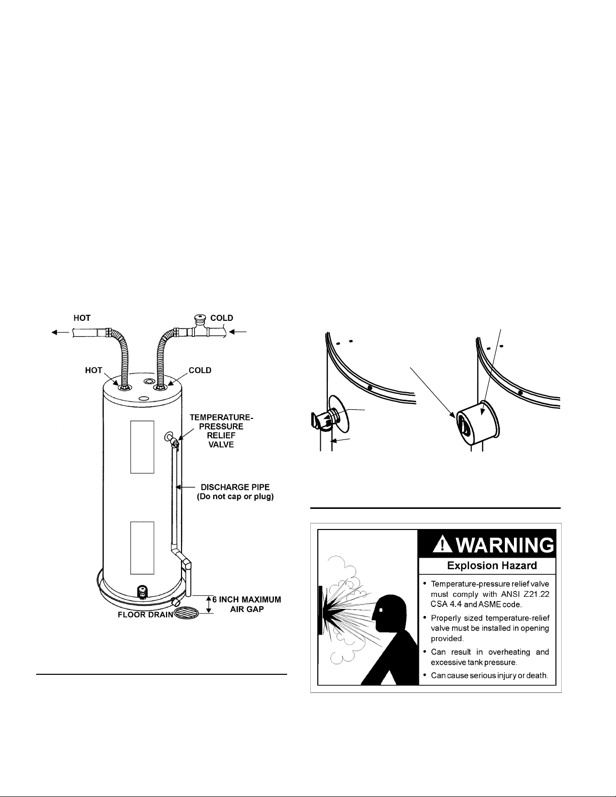
1. Look at the top cover of the water heater. The hot water outlet
is marked hot. Put two or three turns of tefl on tape around
the threaded end of the threaded-to-sweat coupling and
around both ends of the 3/4” threaded nipple. Using fl exible
connectors, connect the hot water pipe to the hot water outlet
of the water heater.
2. Look at the top cover of the water heater. The cold water inlet
is marked cold. Put two or three turns of tefl on tape around
the threaded end of the threaded-to-sweat coupling and
around both ends of the 3/4” threaded nipple. Using fl exible
connectors, connect the cold water pipe to the cold water inlet
of the water heater.
NOTE: Your water heater is insulated to minimize heat
loss from the tank. Further reduction in heat loss can be
accomplished by insulating the hot water lines from the
water heater.
FIGURE 8.
T & P Valve and Pipe Insulation
1. Locate the temperature and pressure relief valve on the water
heater (also known as a T&P relief valve). See Figure 9.
2. Locate the slit running the length of the T&P relief valve
insulation.
3. Spread the slit open and fi t the insulation over the T&P relief
valve. See Figure 9. Apply gentle pressure to the insulation
to ensure that it is fully seated on the T&P Relief Valve. Once
seated, secure the insulation with duct tape, electrical tape, or
equivalent. IMPORTANT: The insulation and tape must not
block the discharge opening or hinder access to the manual
relief lever (Figure 9). Ensure a discharge pipe is installed
into the T&P valve discharge opening per the instructions in
this manual.
4. Locate the hot water (outlet) & cold water (inlet) pipes to the
water heater.
5. Locate the slit running the length of a section of pipe
insulation.
6. Spread the slit open and slip the insulation over the cold
water (inlet) pipe. Apply gentle pressure along the length of
the insulation to ensure that it is fully seated around the pipe.
Also, ensure that the base of the insulation is fl ush with the
water heater. Once seated, secure the insulation with duct
tape, electrical tape, or equivalent.
7. Repeat steps 5 and 6 for the hot water (outlet) pipe.
8. Add additional sections of pipe insulation as needed.
T&P Relief Valve
T&P Relief Valve
Drain Line
Manual Relief Lever
T&P Relief Valve Insulation
FIGURE 9.
Temperature-Pressure Relief Valve
This heater is provided with a properly certifi ed combination
temperature - pressure relief valve by the manufacturer.
The valve is certifi ed by a nationally recognized testing laboratory
that maintains periodic inspection of production of listed
Loading ...
Loading ...
Loading ...