
Loading ...
Loading ...
Installation Instructions
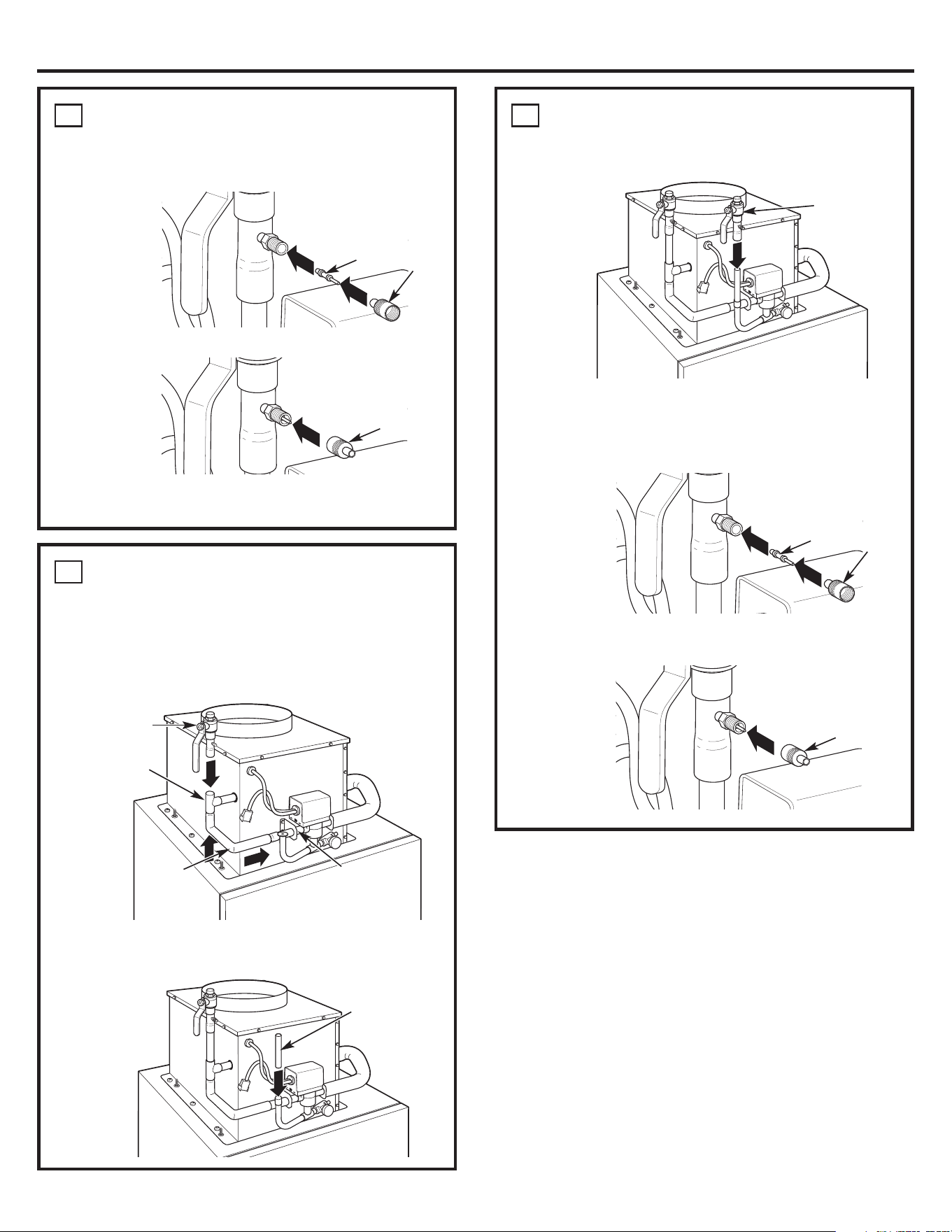
Bypass Connection Option (continued)
3. Place the pressure-release valve onto
the end of the vertical tubing and solder.
4. Screw the provided stems into the air-bleed
valves and tighten finger tight. Using the
supplied air-bleed valve tool, tighten the stem
until snug.
5. Put the cap over the stem and tighten finger
tight.
B
Pressure-
release
valve
Stem
Cap/air-bleed
valve tool
Cap/
air-bleed
valve tool
Standard Connection Option (continued)
4. Screw the provided stems into the bleed valves
and tighten finger tight. Using the supplied
air-bleed valve tool, tighten the stem until snug.
5. Put the cap over the stem and tighten finger tight.
The Standard Connection Option is now complete.
Skip to Step 5 and proceed with the installation.
A
Stem
Cap/air-bleed
valve tool
Cap/
air-bleed
valve tool
Bypass Connection Option
1. Connect the copper bypass tube to the bypass
tube leading from the valve and connect it to the
T-fitting in the outlet tube. Connect the shut-off
valve to the other end of the T-fitting using a
suitable length of 1/2″ copper tubing. Solder
connections.
2. Install the vertical tubing into the tubing
on the Hydronic Heater and solder.
B
Shut-off
valve
T-fitting
Copper
bypass
tube
Bypass tube
Vertical tubing,
user-supplied, cut
to desired length
3
Loading ...
Loading ...
Loading ...