Count on it.
0
CL
0
Form No. 3369-575 Rev A
TimeCutter_ SS 4235, SS4260, SS
5000 and SS 5060 Riding Mowers
Model No. 74624mSerial No. 311000001 and Up
Model No. 74625mSerial No. 311000001 and Up
Model No. 74626_Serial No. 311000001 and Up
Model No. 74630_Serial No. 311000001 and Up
Model No. 74632_Serial No. 311000001 and Up
To register your product or download an Operator's Manual or Parts Catalog at no charge, go to www.Toro.com. Original Instructions (EN)
This machine is a ride-on, rotary-blade lawnmower
intended to be used by homeowners in residential
applications. It is primarily designed for cutting grass
on well-maintained lawns. It is not designed for cutting
brush, mowing grass and other growth alongside
highways, or for agricultural uses.
CALIFORNIA
Proposition 65 Warning
The engine exhaust from this product
contains chemicals known to the State of
California to cause cancer, birth defects,
or other reproductive harm.
Important: This engine is not equipped with a
spark arrester muffler. It is a violation of California
Public Resource Code Section 4442 to use or operate
the engine on any forest-covered, brush-covered, or
grass-covered land. Other states or federal areas
may have similar laws.
This spark ignition system complies with Canadian
ICES-002.
Removing standard original equipment parts and
accessories may alter the warranty, traction, and
safety of the machine. Failure to use original Toro
parts could cause serious injury or death. Making
unauthorized changes to the engine, fuel or venting
system, may violate EPA and CARB regulations.
Replace all parts including, but not limited to, tires,
belts, blades, and fuel system components with
original Toro parts.
The enclosed Engine Owner's Manual is supplied
for information regarding the US Environmental
Protection Agency (EPA) and the California
Emission Control Regulation of emission systems,
maintenance, and warranty. Replacements may be
ordered through the engine manufacturer.
For models with stated engine horsepower, the gross
horsepower of the engine was laboratory rated by the
engine manufacturer in accordance with SAE J1940.
As configured to meet safer B emission, and operating
requirements, the actual engine horsepower on this class
of lawn mower will be significantly lower.
Introduction
Read this information carefully to learn how to operate
and maintain your product properly and to avoid injury
and product damage. You are responsible for operating
the product properly and safely.
You may contact Toro directly at www.Toro.com for
product and accessory information, help finding a
dealer, or to register your product.
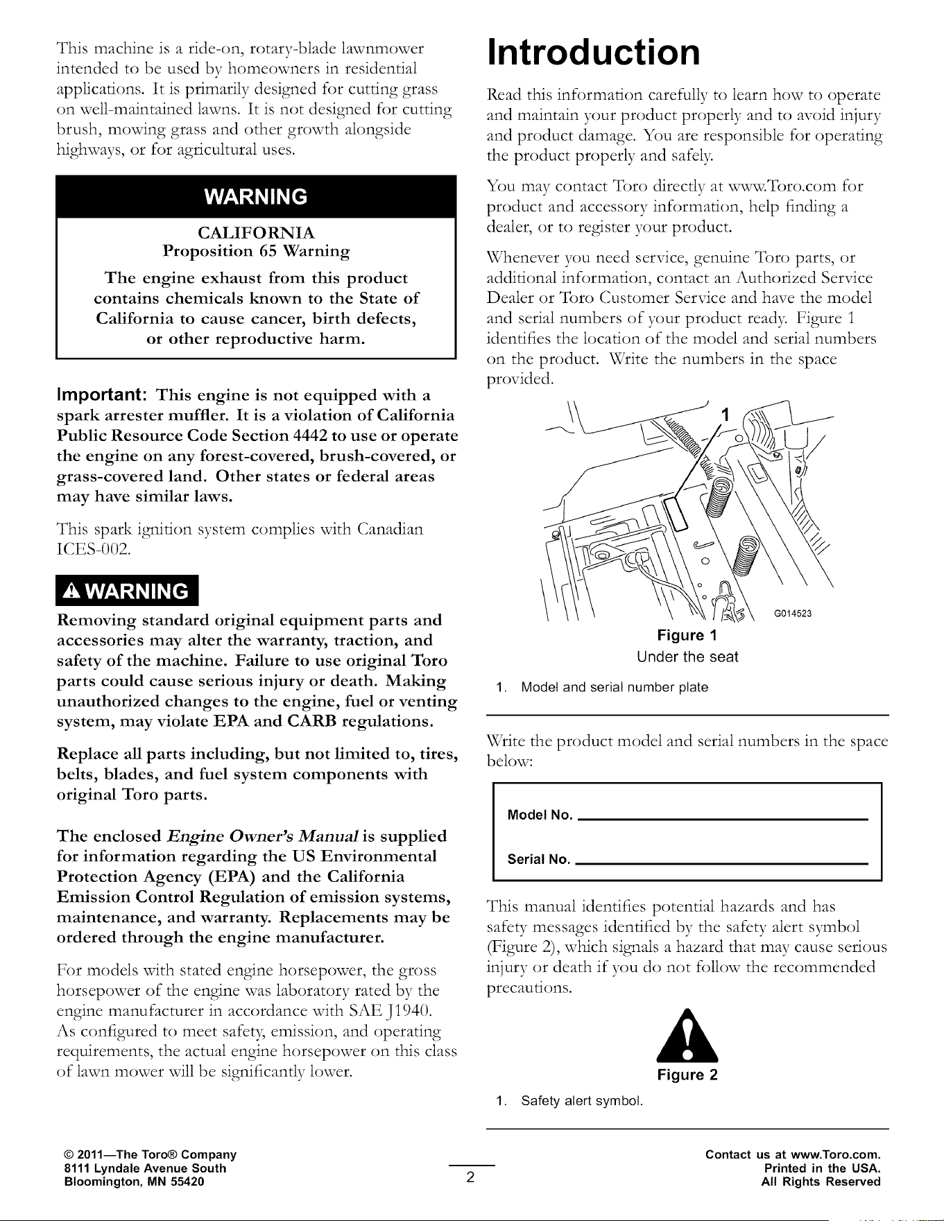
Whenever you need service, genuine Toro parts, or
additional information, contact an Authorized Service
Dealer or Toro Customer Service and have the model
and serial numbers of your product read> Figure i
identifies the location of the model and serial numbers
on the product. Write the numbers in the space
provided.
\\
Figure 1
Under the seat
1. Model and serial number plate
G014523
Write the product model and serial numbers in the space
below:
Model No.
Serial No.
This manual identifies potential hazards and has
safety messages identified by the safety alert symbol
(Figure 2), which signals a hazard that may cause serious
injury or death if you do not follow the recommended
precautions.
Figure 2
1. Safety alert symbol.
© 2011--The Toro® Company
8111 Lyndale Avenue South
Bloomington, MN 55420
Contact us at www.Toro.com.
Printed in the USA.
All Rights Reserved

This manual uses two other words to highlight
information. Important calls attention to special
mechanical information and Note emphasizes general
information worthy of special attention.
Contents
Introduction ................................................................. 2
Safety ........................................................................... 4
Safe Operating Practices ....................................... 4
Toro Riding Mower Safety .................................... 6
Slope Indicator ..................................................... 7
Safety and Instructional Decals ............................. 8
Product Overview ...................................................... 14
Controls ............................................................. 15
Operation ................................................................... 16
Think Safety First ............................................... 16
Before Starting ................................................... 18
Starting the Engine ............................................. 19
Operating the Blades .......................................... 20
Testing the Safety Interlock System ..................... 20
Stopping the Engine ........................................... 2i
DrNing ............................................................... 2i
Stopping the Machine ......................................... 22
Adjusting the Height of Cut ................................ 22
Positioning the Seat ............................................ 23
Adjusting the Motion Control Levers .................. 23
Pushing the Machine by Hand ............................. 24
Grass Deflector .................................................. 24
Operating Tips ................................................... 25
Maintenance ............................................................... 27
Recommended Maintenance Schedule(s) ................ 27
Premaintenance Procedures .................................... 28
Raising the Seat .................................................. 28
Lubrication ............................................................. 28
Greasing the Bearings ......................................... 28
Engine Maintenance ............................................... 29
Servicing the Air Cleaner .................................... 29
Servicing the Engine Oil ..................................... 30
Servicing the Spark Plug ..................................... 32
Cleaning the Cooling System ............................... 33
Fuel System Maintenance ....................................... 33
Replacing the In-line Fuel Filter .......................... 33
Servicing the Emissions Filter ............................. 34
Electrical System Maintenance ................................ 34
Charging the Battery ........................................... 34
Servicing the Fuses ............................................. 35
Drive System Maintenance ..................................... 36
Checldng the Tire Pressure ................................. 36
Releasing the Electric Brake ................................ 36
Mower Maintenance ............................................... 37
Servicing the Cutting Blades ............................... 37
Leveling the Mower Deck ................................... 40
Removing the Mower ......................................... 42
Mower Belt Maintenance .................................... 43
Installing the Mower ........................................... 44
Replacing the Grass Deflector ............................. 44
Cleaning ................................................................. 45
Washing the Underside o f the Mower .................. 45
Storage ....................................................................... 46
Cleaning and Storage .......................................... 46
Troubleshooting ......................................................... 48
Schematics ................................................................. 50
Safety
This machine meets or exceeds the B71.1-2003
specifications of the American National Standards
Institute, in effect at the time of production.
However, improper use or maintenance by the
operator or owner can result in injury. To reduce
the potential for injury, comply with these safety
instructions and always pay attention to the
safety alert symbol, which means CAUTION,
WARNING, or DANGER-"personal safety
instruction." Failure to comply with the instruction
may result in personal injury or death.
Safe Operating Practices
This product is capable of amputating hands and
feet and throwing objects. Always follow all safety
instructions to avoid serious injury or death.
The following instructions are from ANSI standard
B7I.I-2003. All the language within this ANSI standard
applies to this machine; however, due to the application
of the standard across ma W different types of products
some statements can seem general or misleading. In
these instances, _[bro has refined the statement to convey
the meaning of the standard while better matching
the product this Operator's Mazual pertains. Safety
information in addition to the instructions found in
the ANSI standard below can be found in _fbro Riding
Mower Safety at the end of this section.
General Operation
• Read, understand, and follow all instructions in
the operator's manual and on the machine before
starting.
• Do not place hands or feet near rotating parts or
under the machine. Keep clear of the discharge
opening at all times.
• iMlow only responsible adults who are familiar with
the instructions to operate the machine.
• Clear the area of objects such as rocks, toys, wire,
etc., which could be picked up and thrown by the
blade.
• Be sure the area is clear of other people before
mowing. Stop the machine if anyone enters the area.
• Never carry passengers.
• Do not mow in reverse unless absolutely necessar>
Always look down and behind before and while
backing up.
• Be aware of the mower discharge direction and do
not point it at awone. Avoid discharging material
against a wall or obstruction. Material may ricochet
back toward the operator. Stop the blade(s) when
crossing gravel surfaces.
Do not operate the machine without deflector,
discharge cover or entire grass collection system in
place and working.
Be alert, slow down and use caution when malting
turns. Look behind and to the side before changing
directions.
• Never leave a running machine unattended. Always
turn off blades, set parldng brake, stop engine, and
remove key before dismounting.
• Turn off blades when not mowing. Stop the engine,
wait for all parts to come to a complete stop
and remove the key before cleaning the machine,
removing the grass catcher or unclogging the
discharge chute.
• Operate the machine only in daylight or good
artificial light.
• Do not operate the machine while under the
influence of alcohol or drugs.
• Watch for traffic when operating near or crossing
roadways.
• Use extra care when loading or unloading the
machine into a trailer or truck.
Always wear eye protection when operating the
mower.
• Data indicates that operators, age 60 years and
above, are involved in a large percentage of riding
mower-related injuries. Operators should evaluate
their ability to operate the tiding mower safely
enough to protect themselves and others from
serious injur>
• Always follow the recommendations for aW
application o f counterweights.
• Lightning can cause severe injury or death. If
lightning is seen or thunder is heard in the area, do
not operate the machine; seek shelter.
Slope Operation
Slopes are a major factor related to loss of control and
tip-over accidents, which can result in severe injury or
death. Operation on all slopes requires extra caution. If
you cannot back up the slope or if you feel uneasy on it,
do not mow it.
Do not mow slopes greater than 15 degrees.
Watch for ditches, holes, rocks, dips, and rises that
change the operating angle, as rough terrain could
overturn the machine.
• Choose a low ground speed so you will not have to
stop while operating on a slope.
• Do not mow slopes when grass is wet. Slippery
conditions reduce traenon and could cause sliding
and loss of control.
• Always keep the drive wheels engaged when going
down slopes.
• Reduce speed and use extreme caution on slopes.
• Do not make sudden turns or rapid speed changes.
• Remove or mark obstacles such as rocks, tree limbs,
etc. from the mowing area. Tall grass can hide
obstacles.
• Avoid sudden starts when mowing uphill because
the mower may tip backwards.
• Be aware that loss of traction may occur going
downhill. Weight transfer to the front wheels may
cause drive wheels to shp and cause loss of braking
and steering.
• Always avoid sudden starting or stopping on a slope.
If tires lose traction, stop the machine, disengage the
blades and proceed slowly oft- the slope.
• Use extreme care with grass catchers or other
attachments. These can change the stability of the
machine and cause loss of control.
• Do not try to stabilize the machine by putting your
foot on the ground.
• Do not mow near drop-offs, ditches, steep banks
or water. Wheels dropping over edges can cause
rollovers, which may result in serious injur 5 death
or drowning.
• Use a walk behind mower and/or a hand trimmer
near drop-oft_, ditches, steep banks or water.
Children
Tragic accidents can occur if the operator is not alert to
the presence of children. Children are often attracted to
the machine and the mowing activit> Never assume that
children will remain where you last saw them.
• Keep children out of the mowing area and under
the watchful care of another responsible adult, not
the operator.
• Be alert and turn the machine oft-if children enter
the area.
Before and while bacldng or changing direction, look
behind, down, and side-to-side for small children.
Never carry children, even with the blades oft. They
may fall oft- and be seriously injured or interfere with
safe machine operation.
• Children who have been given rides in the past may
suddenly appear in the mowing area for another ride
and be run over or backed over by the mower.
• Never allow children to operate the machine.
• Use extra care when approaching blind corners,
shrubs, trees, the end of a fence or other objects that
may obscure vision.
Towing
A hitch kit is available for this machine and can be
obtained by contacting an Authorized Toro Dealer.
Do not tow without first installing this manufacturer
approved hitch. The following guidelines apply when
towing with the approved hitch kit installed.
• Tow only with a machine that has a hitch designed
for towing. Do not attach towed equipment except
at the hitch point.
• Follow the manufacturer's recommendation for
weight limits for towed equipment and towing on
slopes.
• Never allow children or others in or on towed
equipment.
• On slopes, the weight of the towed equipment may
cause loss of traction and loss of control.
• Travel slowly and allow extra distance to stop.
Service
Safe Handling of Gasoline:
To avoid personal injury or property damage, use extra
care when handling gasoline and other fuels. They are
flammable and the vapors are explosive.
• Extinguish all cigarettes, cigars, pipes and other
sources of ignition.
• Use only an approved container.
• Never remove the gas cap or add fuel when the
engine is running. Allow the engine to cool before
refueling.
• Never refuel the machine indoors.
• Never store the machine or fuel container inside
where there is an open flame, such as near a water
heater or furnace.
• Never fill containers inside a vehicle or on a truck or
trailer with a plastic liner. Always place containers on
the ground away from your vehicle before filling.
• Remove gas-powered equipment from the truck
or trailer and refuel it on the ground. If this is not
possible, then refuel such equipment with a portable
container,ratherthan from agasolinedispenser
nozzle.
• Keepthenozzlein contactwith therim of the fuel
tankor containeropeningatalltimes until the fueling
is complete. Do not use a nozzle lock-open device.
• If fuel is spilled on clothing, change clothing
immediatel>
• Never overfill the fuel tank. Replace gas cap and
tighten securely
General Service:
• Never operate a machine inside a closed area. Engine
exhaust contains carbon monoxide, which is an
odorless, deadly poison that can kill you.
• Keep nuts and bolts tight, especially the blade
attachment bolts. Keep equipment in good
condition.
• Never tamper with safety devices. Check their
proper operation regular1>
• Keep the machine free of grass, leaves, or other
debris build-up. Clean up oil or fuel spillage fuel
soaked debris. Allow the machine to cool before
storing.
• Stop and inspect the equipment if you strike an
object. Repair, if necessar 5 before restarting.
• Never make any adjustments or repairs with the
engine running.
• Grass catcher components are subject to wear,
damage and deterioration, which could expose
moving parts or allow objects to be thrown.
Frequently check components and replace with
manufacturers' recommended parts, when necessar>
• Mower blades are sharp and can cut. Wrap the
blade(s) or wear gloves, and use extra caution when
servicing them.
• Check for proper brake operation frequentl> Adjust
and service as required.
• Maintain or replace safety and instruction decals as
necessary.
Use only genuine Toro replacement parts to ensure
that original standards are maintained.
Toro Riding Mower Safety
The following hst contains safety information specific to
Toro products or other safety information that you must
know that m W not be included in the ANSI standards.
• Stop the engine, move the motion control levers to
neutral and outward to the park position, disengage
the blade control switch, remove key before and
disconnect spark plug wire(s) performing aW service,
repairs, maintenance or adjustments.
Keep hands, feet, hair, and loose clothing away from
attachment discharge area, underside of mower and
any moving parts while engine is running.
Do not touch equipment or attachment parts which
may be hot from operation. Allow to cool before
attempting to maintain, adjust or service.
Battery acid is poisonous and can cause burns. Avoid
contact with skin, eyes, and clothing. Protect your
face, eyes, and clothing when working with a batter>
Battery gases can explode. Keep cigarettes, sparks
and flames away from batter>
Use only Toro approved attachments. Warranty may
be voided if used with unapproved attachments.
If loading the machine onto a trailer or truck, use a
single, full-width ramp only The ramp angle should
not exceed 15 degrees.
Slope Indicator
Ii\ \
| i l\
\
|ll\
Ill \
| II \
| II \
| 1 l \
I I \ \
I I \ \
I l \ \
I l \ \
\
I l \
I l \ \
\
I l
\
! l
\
I l
\
! l \
| l
\
\
\
\
\
\ \
! l \ \
I 1 l \
I l \ \
I l \ \
I l \ \
I 1
I !
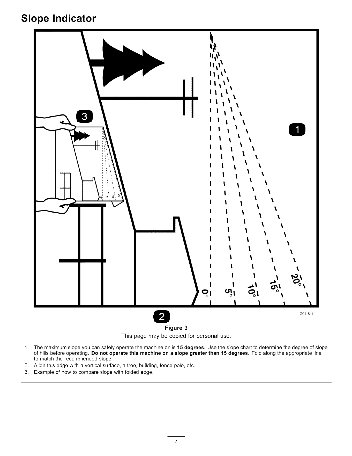
Figure 3
This page may be copied for personal use.
0
\
G011841
1. The maximum slope you can safely operate the machine on is 15 degrees. Use the slope chart to determine the degree of slope
of hills before operating. Do not operate this machine on a slope greater than 15 degrees. Fold along the appropriate line
to match the recommended slope.
2. Align this edge with a vertical surface, a tree, building, fence pole, etc.
3. Example of how to compare slope with folded edge.
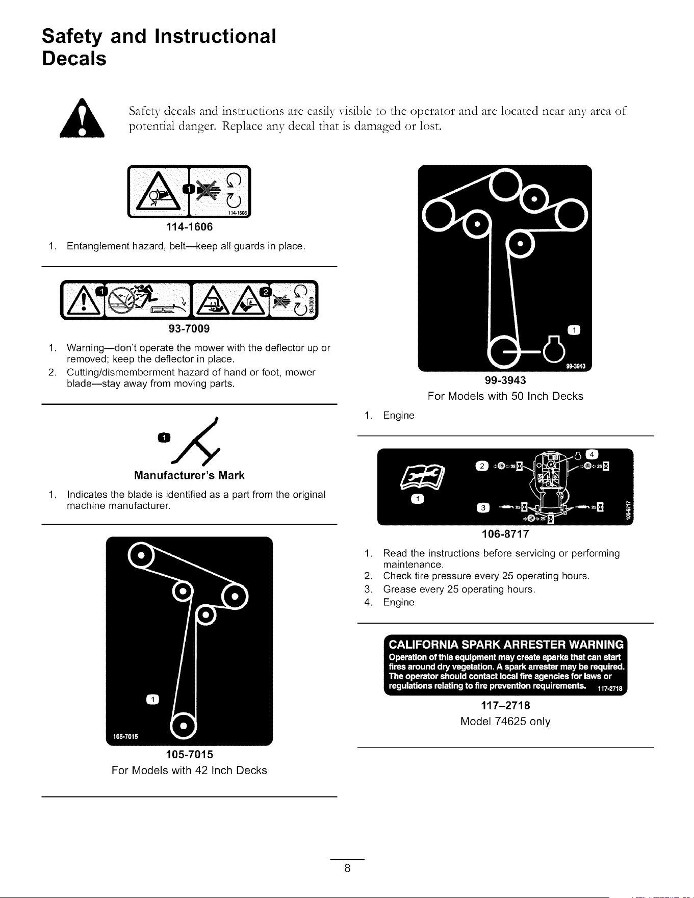
Safety and Instructional
Decals
Safety decals and instructions are easily visible to the operator and are located near any area of
potential danger. Replace any decal that is damaged or lost.
1144¢C_
114-1606
1. Entanglement hazard, belt--keep all guards in place.
93-7009
1. Warning--don't operate the mower with the deflector up or
removed; keep the deflector in place.
2. Cutting/dismemberment hazard of hand or foot, mower
blade--stay away from moving parts.
1,
Manufacturer's Mark
Indicates the blade is identified as a part from the original
machine manufacturer.
105-7015
For Models with 42 Inch Decks
1. Engine
99-3943
For Models with 50 Inch Decks
106-8717
1. Read the instructions before servicing or performing
maintenance.
2. Check tire pressure every 25 operating hours.
3. Grease every 25 operating hours.
4. Engine
117-2718
Model 74625 only
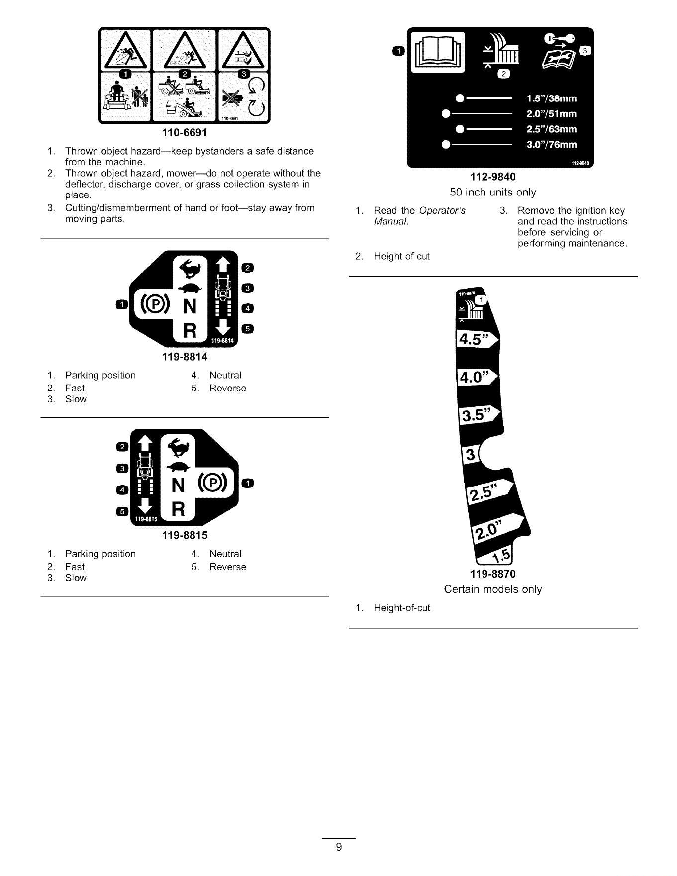
110-6691
0
1. Thrown object hazard--keep bystanders a safe distance
from the machine.
2. Thrown object hazard, mower--do not operate without the
deflector, discharge cover, or grass collection system in
place.
3. Cutting/dismemberment of hand or foot--stay away from
moving parts.
IDI
1. Parking position
2. Fast
3. Slow
119-8814
4.
5.
0
0
0
0
Neutral
Reverse
1,
2,
112-9840
50 inch units only
Read the Operator's
Manual.
Height of cut
3,
Remove the ignition key
and read the instructions
before servicing or
performing maintenance.
0
0
0
0
1. Parking position
2. Fast
3. Slow
N(¢)
119-8815
4.
5.
Neutral
Reverse
II
1,
Height-of-cut
119-8870
Certain models only
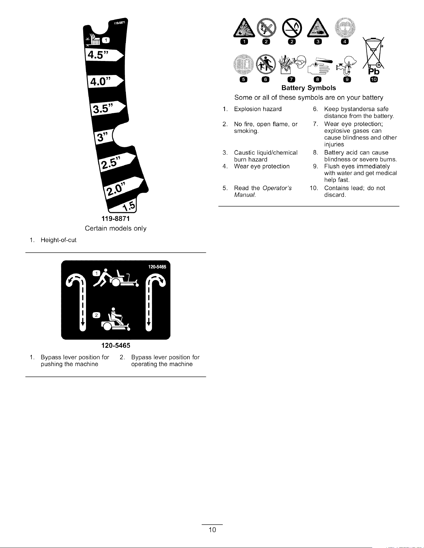
0 0 0 0 0
@
0 0 0 0 0
Battery Symbols
Some or all of these symbols
Q
are on your battery
1. Explosion hazard 6. Keep bystandersa safe
distance from the battery.
2. No fire, open flame, or 7. Wear eye protection;
smoking, explosive gases can
cause blindness and other
injuries
3. Caustic liquid/chemical 8. Battery acid can cause
burn hazard blindness or severe burns.
4. Wear eye protection 9. Flush eyes immediately
with water and get medical
help fast.
5. Read the Operator's 10. Contains lead; do not
Manual. discard.
1,
Height-of-cut
119-8871
Certain models only
120-5465
1. Bypass lever position for
pushing the machine
2. Bypass lever position for
operating the machine
10
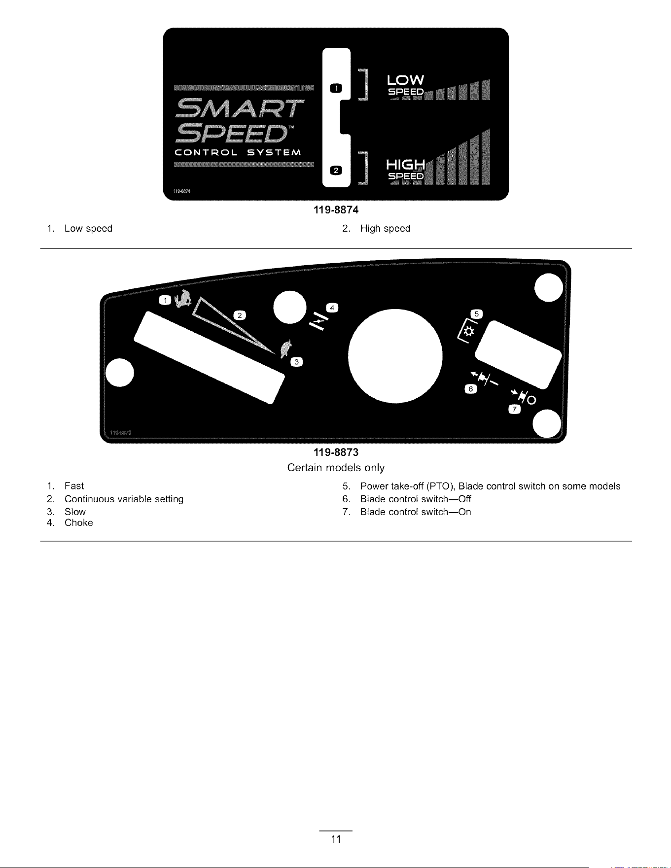
1. Low speed
119-8874
2. High speed
1. Fast
2. Continuous variable setting
3. Stow
4. Choke
119-8873
Certain models only
5. Power take-off (PTO), Blade control switch on some models
6. Blade control switch--Off
7. Blade control switch--On
11
1. Fast
2. Continuous variable setting
3. Stow
4. Choke
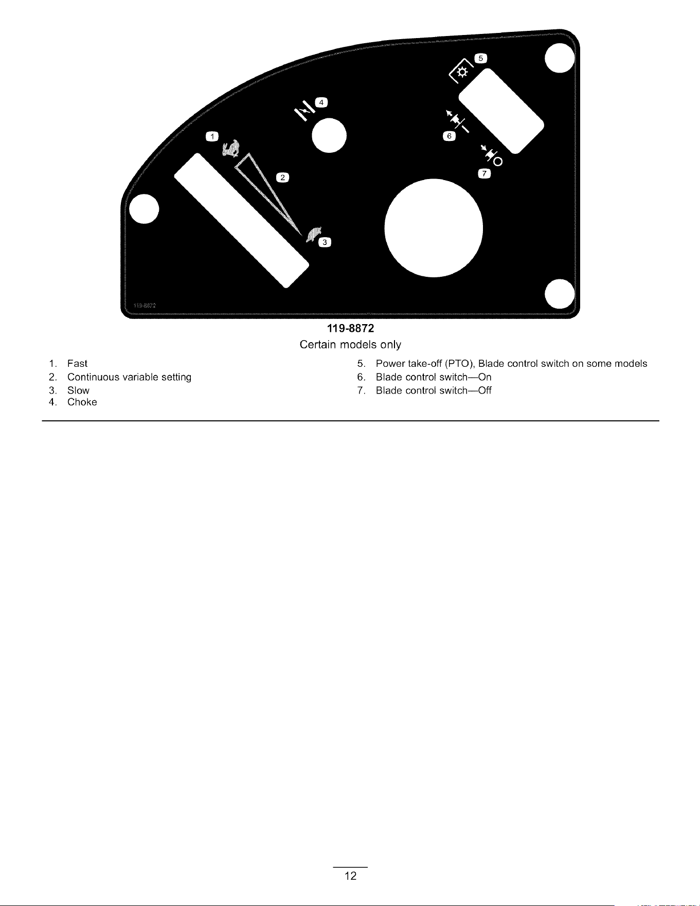
119-8872
Certain models only
5. Power take-off (PTO), Blade control switch on some models
6. Blade control switch--On
7. Blade control switch--Off
12
1,
2.
3,
4,
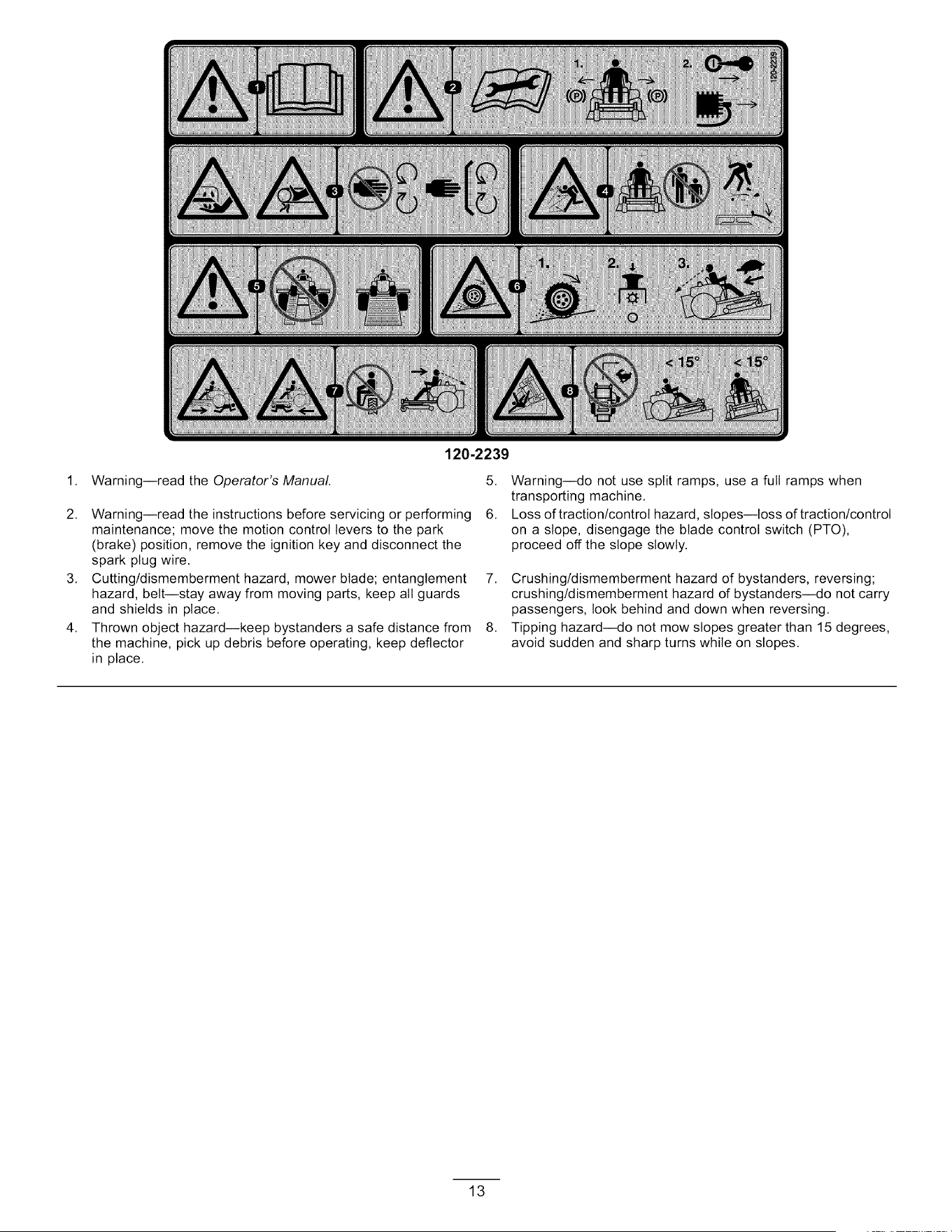
Warning--read the Operator's Manual.
120-2239
Warning--read the instructions before servicing or performing
maintenance; move the motion control levers to the park
(brake) position, remove the ignition key and disconnect the
spark plug wire.
Cutting/dismemberment hazard, mower blade; entanglement
hazard, belt--stay away from moving parts, keep all guards
and shields in place.
Thrown object hazard--keep bystanders a safe distance from
the machine, pick up debris before operating, keep deflector
in place.
5. Warning--do not use split ramps, use a full ramps when
transporting machine.
6. Loss of traction/control hazard, slopes--toss of traction/control
on a slope, disengage the blade control switch (PTO),
proceed off the slope slowly.
7. Crushing/dismemberment hazard of bystanders, reversing;
crushing/dismemberment hazard of bystanders--do not carry
passengers, look behind and down when reversing.
8. Tipping hazard--do not mow slopes greater than 15 degrees,
avoid sudden and sharp turns while on slopes.
13
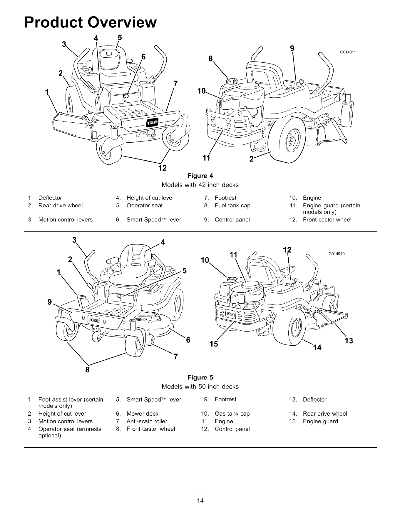
Product Overview
4 5
2
\
6
7
11
12
Figure 4
Models with 42 inch decks
1. Deflector 4. Height of cut lever 7. Footrest
2. Rear drive wheel 5. Operator seat 8. Fuel tank cap
3. Motion control levers 6. Smart Speed rM lever 9. Control panel
2
9
G014911
10. Engine
11. Engine guard (certain
models only)
12. Front caster wheel
2
8
1. Foot assist lever (certain 5.
models only)
2. Height of cut lever 6.
3. Motion control levers 7.
4. Operator seat (armrests 8.
optional)
7
12
11 "_ / _'_ G014910
10 _ \
15 _"_/_14 13
Figure 5
Models with 50 inch decks
Smart Speed rM lever
Mower deck
Anti-scalp roller
Front caster wheel
9. Footrest
10. Gas tank cap
11. Engine
12. Control panel
13. Deflector
14. Rear drive wheel
15. Engine guard
14

Controls
Become familiar with all of the controls in Figure 4,
Figure 5, and Figure 6 before you start the engine and
operate the machine.
2
1
Figure 6
Control Panel
1. Throttle 3. Blade control switch
(power take-off)
2. Ignition switch 4. Choke
Motion Control Levers and Park
Position
The motion control levers are speed sensitive controls of
independent wheel motors. Moving a lever forward or
backward turns the wheel on the same side forward or in
reverse; wheel speed is proportional to the amount the
lever is moved. Move the control levers outward from
the center to the park position and exit the machine
(Figure i7). Always position the motion control levers
into the park position when you stop the machine or
leave it unattended.
Smart Speed TM Control System Lever
The Smart Speed TM Control System lever, located below
the operating position, gives the operator a choice to
drive the machine at two speed ranges, high and low
(Figure 7).
Ignition Switch
The ignition switch has three positions, Off, Run and
Start. The key will turn to Start and move back to
Run upon release. Turning the key to the Off position
will stop the engine; however, always remove the key
when leaving the machine to prevent someone from
accidentally starting the engine (Figure 6).
Throttle Control
"['he throttle controls the engine speed and it has a
continuous variable setting from Slow to Fast (Figure 6).
Choke Control
Pull up on the Choke control until it stops to choke the
engine (Figure 6). Push down on the Choke control for
normal engine operation
Blade Control Switch (Power Take-Off)
The blade control switch, represented by a power
take-off _TO) symbol, engages and disengages power
to the mower blades (Figure 6).
1. Smart speed lever
Figure 7
G014475
Fuel Window
The fuel window located on the left hand side of the
machine can be used to veri_, the presence of gasoline
in the tank (Figure 8).
G014521
1,
J 1
Figure 8
Fuel presence window
15
Height-of-Cut Lever
The height oK cut lever allows the operator to lower
and raise the deck from the seated position. When the
lever is moved up, toward the operator the deck is raised
from the ground and when moved down, away from the
operator it is lowered toward the ground. Only adjust the
height of cut while machine is not moving {Figure 2i).
Operation
Note: Determine the leKt and right sides of the
machine from the normal operating position.
Think Safety First
Operating Safety
Please carefully read all of the safety instructions and
decals in the safety section. Knowing this information
could help you, your famil3; pets or bystanders avoid
injur>
Mowing on wet grass or steep slopes can cause
sliding and loss of control.
Wheels dropping over edges can cause rollovers,
which may result in serious injury, death or
drowning.
A loss of traction is a loss of steering control.
To avoid loss of control and possibility of rollover:
• Do not mow near drop-offs or near water.
• Do not mow slopes greater than 15 degrees.
• Reduce speed and use extreme caution on
slopes.
• When mowing slopes, gradually work from
lower to higher areas on the incline.
• Avoid sudden turns or rapid speed changes.
• Turn up, into an incline when changing
directions on slopes. Turning down the slope
reduces traction.
Attachments change the handling
characteristics of the machine. Use
extra caution when using attachments with the
machine.
16
2
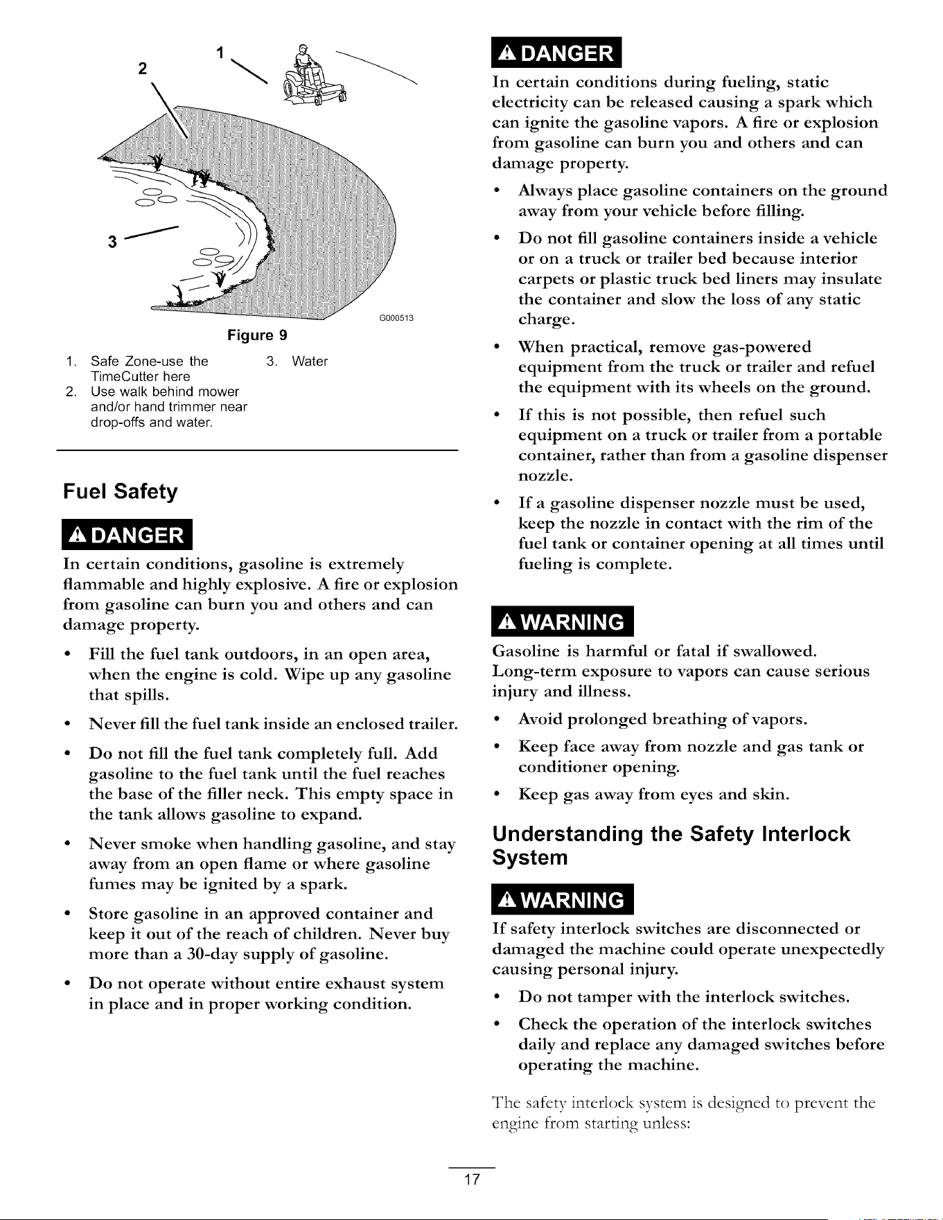
Figure 9
1. Safe Zone-use the
TimeCutter here
2. Use walk behind mower
and/or hand trimmer near
drop-offs and water.
3. Water
G000513
Fuel Safety
In certain conditions, gasoline is extremely
flammable and highly explosive. A fire or explosion
from gasoline can burn you and others and can
damage property.
• Fill the fuel tank outdoors, in an open area,
when the engine is cold. Wipe up any gasoline
that spills.
• Never fill the fuel tank inside an enclosed trailer.
Do not fill the fuel tank completely full. Add
gasoline to the fuel tank until the fuel reaches
the base of the filler neck. This empty space in
the tank allows gasoline to expand.
Never smoke when handling gasoline, and stay
away from an open flame or where gasoline
fumes may be ignited by a spark.
Store gasoline in an approved container and
keep it out of the reach of children. Never buy
more than a 30-day supply of gasoline.
Do not operate without entire exhaust system
in place and in proper working condition.
In certain conditions during fueling, static
electricity can be released causing a spark which
can ignite the gasoline vapors. A fire or explosion
from gasoline can burn you and others and can
damage property.
• Always place gasoline containers on the ground
away from your vehicle before filling.
• Do not fill gasoline containers inside a vehicle
or on a truck or trailer bed because interior
carpets or plastic truck bed liners may insulate
the container and slow the loss of any static
charge.
• When practical, remove gas-powered
equipment from the truck or trailer and refuel
the equipment with its wheels on the ground.
If this is not possible, then refuel such
equipment on a truck or trailer from a portable
container, rather than from a gasoline dispenser
nozzle.
If a gasoline dispenser nozzle must be used,
keep the nozzle in contact with the rim of the
fuel tank or container opening at all times until
fueling is complete.
Gasoline is harmful or fatal if swallowed.
Long-term exposure to vapors can cause serious
injury and illness.
• Avoid prolonged breathing of vapors.
• Keep face away from nozzle and gas tank or
conditioner opening.
• Keep gas away from eyes and skin.
Understanding the Safety Interlock
System
If safety
interlock switches are disconnected or
damaged the machine could operate unexpectedly
causing personal injury.
Do not tamper with the interlock switches.
Check the operation of the interlock switches
daily and replace any damaged switches before
operating the machine.
The safety interlock system is designed to prevent the
engine from starting unless:
17
• The blades are disengaged.
• The motion control levers are in the park position.
The safety interlock system also is designed to stop the
engine whenever the control levers are out of the park
position and you rise from the seat.
Before Starting
Recommended Fuel
Use UNLEADED Regular Gasoline suitable for
automotive use (87 pump octane minimum). Leaded
regular gasoline may be used if unleaded regular is not
available.
Important: Never use methanol, gasoline
containing methanol, or gasohol containing more
than 10 percent ethanol because the fuel system
could be damaged. Do not mix oil with gasoline.
Using Stabilizer/Conditioner
Use a fuel stabilizer/conditioner in the machine to
provide the following benefits:
• Keeps gasoline fresh during storage of 30 days or
less. For longer storage it is recommended that the
fuel tank be drained.
• (;leans the engine while it runs.
• Eliminates gum-like varnish buildup in the fuel
system, which causes hard starting.
Add the correct amount of gas stabilizer/conditioner
to the gas.
Note: A fuel stabilizer/conditioner is most effective
when mixed with fresh gasoline. To minimize the
chance of varnish deposits in the fuel system, use fuel
stabilizer at all times.
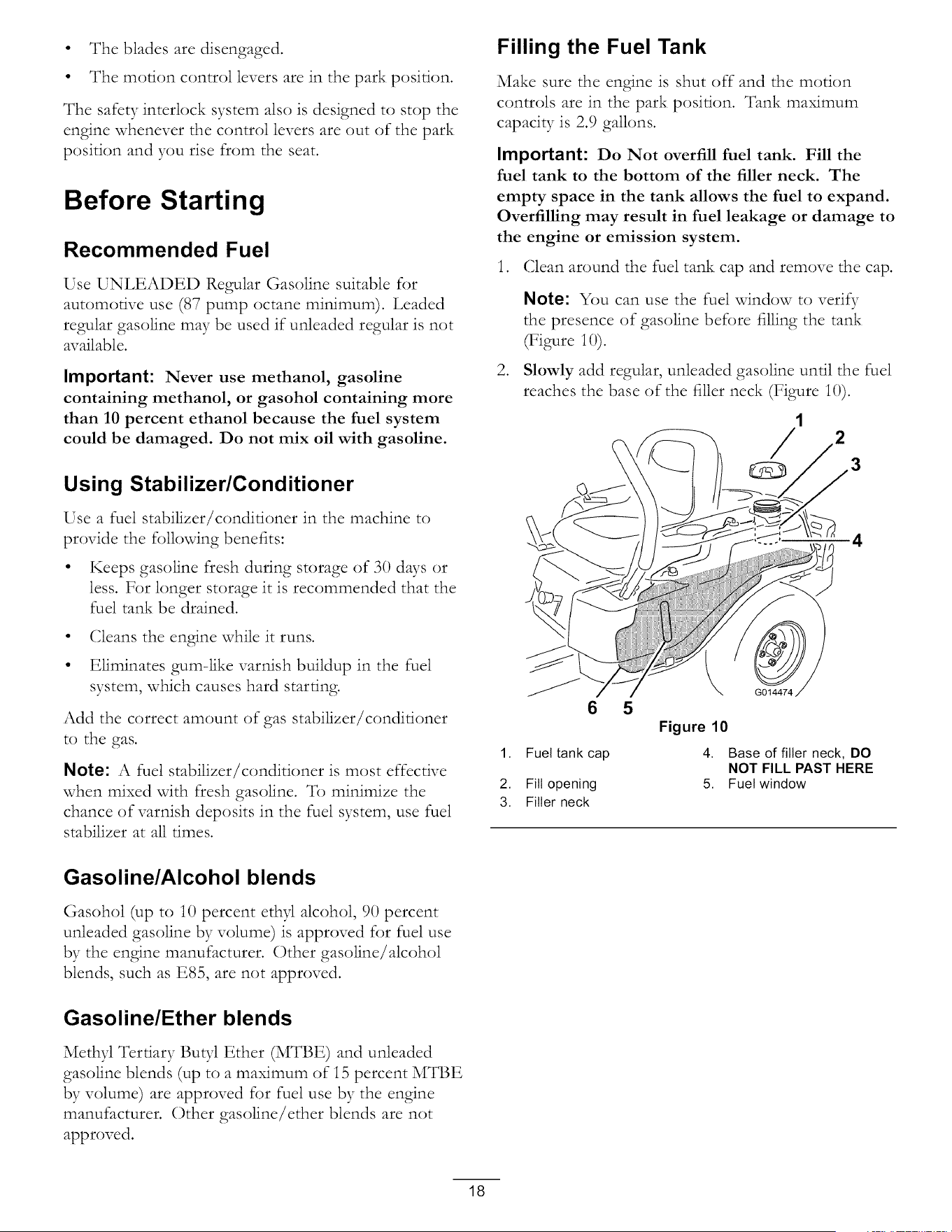
Filling the Fuel Tank
Make sure the engine is shut off and the motion
controls are in the park position. Tank maximum
capacity is 2.9 gallons.
Important: Do Not overfill fuel tank. Fill the
fuel tank to the bottom of the filler neck. The
empty space in the tank allows the fuel to expand.
Overfilling may result in fuel leakage or damage to
the engine or emission system.
1. (;lean around the fuel tank cap and remove the cap.
Note: You can use the fuel window to veri_
the presence of gasoline before filling the tank
(Figure 10).
Slowly add regular, unleaded gasoline until the fuel
reaches the base of the filler neck (Figure i0).
G014474
.
1,
2.
3.
6
Fuel tank cap
Fill opening
Filler neck
5
Figure 10
4.
5,
1
2
4
Base of filler neck, DO
NOT FILL PAST HERE
Fuel window
Gasoline/Alcohol blends
Gasohol (up to 10 percent ethyl alcohol, 90 percent
unleaded gasoline by volume) is approved for fuel use
by the engine manufacturer. Other gasoline/alcohol
blends, such as E85, are not approved.
Gasoline/Ether blends
Methyl Tertiary Butyl Ether (MTBE) and unleaded
gasoline blends (up to a maximum of i5 percent MTBE
by volume) are approved for fuel use by the engine
manufacturer. Other gasoline/ether blends are not
approved.
18
G014895 2
1,
2.
3
Figure 11
Fill opening 3. Fuel
Base of filler neck, DO 4. Empty space for fuel
NOT FILL PAST HERE expansion.
.
Important: Do Not overfill fuel tank. Fill
the fuel tank to the bottom of the filler neck.
The empty space in the tank allows the fuel to
expand. Overfilling may result in fuel leakage
or damage to the engine or emission system.
Install the fuel tank cap securely and tighten until it
"clicks". Wipe up any gasoline that may have spilled.
Checking the Engine Oil Level
Befi)re you start the engine and use the machine, check
the oil level in the engine crankcase; refer to Checking
the Oil Level in the Engine Maintenance section.
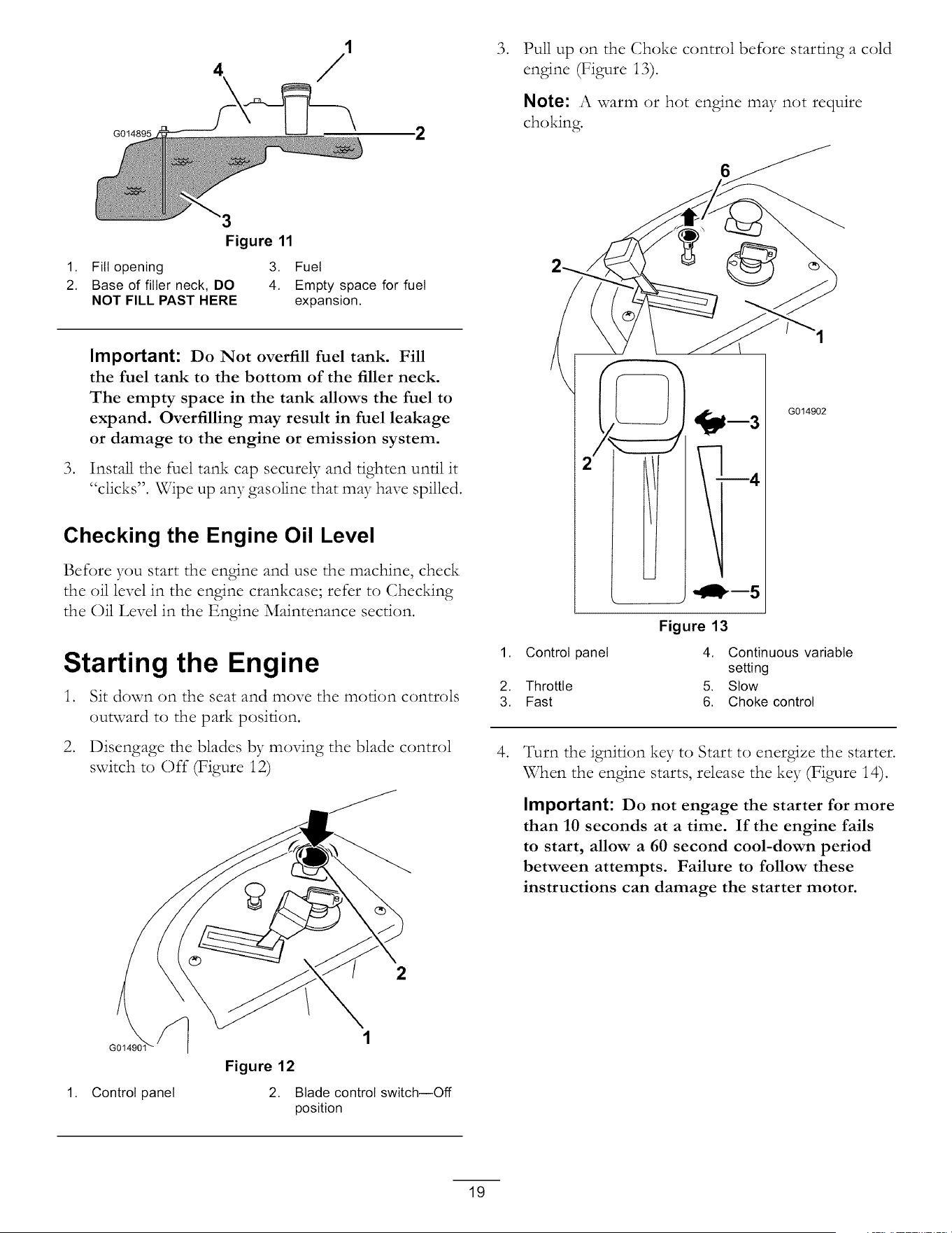
Starting the Engine
1. Sit down on the seat and move the motion controls
outward to the park position.
2. Disengage the blades by moving the blade control
switch to Off (Figure 12)
2
1. Control panel
1
Figure 12
2. Blade control switch--Off
position
.
Pull up on the Choke control before starting a cold
engine (Figure 13).
Note: A warm or hot engine may not require
choking.
6
4
Figure 13
G014902
1. Control panel 4. Continuous variable
setting
2. Throttle 5. Stow
3. Fast 6. Choke control
.
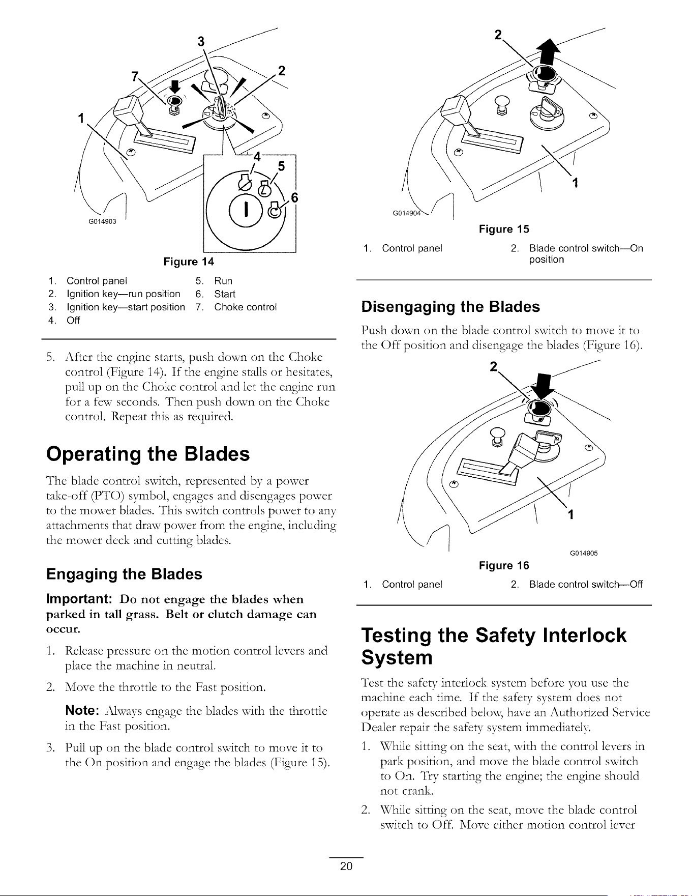
Turn the ignition key to Start to energize the starter.
When the engine starts, release the key (Figure 14).
Important: Do not engage the starter for more
than 10 seconds at a time. If the engine fails
to start, allow a 60 second cool-down period
between attempts. Failure to follow these
instructions can damage the starter motor.
19
3
2
G014903
Figure 14
1. Control panel 5. Run
2. Ignition key--run position 6. Start
3. Ignition key--start position 7. Choke control
4. Off
.
After the engine starts, push down on the Choke
control (Figure i4). If the engine stalls or hesitates,
pull up on the Choke control and let the engine run
for a few seconds. Then push down on the Choke
control. Repeat this as required.
2
\
1. Control panel
Figure 15
2. Blade control switch--On
position
Disengaging the Blades
Push down on the blade control switch to move it to
the Off position and disengage the blades (Figure 16).
2
\
Operating the Blades
The blade control switch, represented by a power
take-off _TO) symbol, engages and disengages power
to the mower blades. This switch controls power to any
attachments that draw power from the engine, including
the mower deck and cutting blades.
Engaging the Blades
Important: Do not engage the blades when
parked in tall grass. Belt or clutch damage can
occur.
.
Release pressure on the motion control levers and
place the machine in neutral.
2. Move the throttle to the Fast position.
.
Note: Always engage the blades with the throttle
in the Fast position.
Pull up on the blade control switch to move it to
the On position and engage the blades (Figure 15).
1. Control panel
G014905
Figure 16
2. Blade control switch--Off
Testing the Safety Interlock
System
Test the safety interlock system before you use the
machine each time. If the safety system does not
operate as described below, have an Authorized Service
Dealer repair the safety system immediatel>
1. While sitting on the seat, with the control levers in
park position, and move the blade control switch
to On. Try starting the engine; the engine should
not crank.
2. While sitting on the seat, move the blade control
switch to Off. Move either morion control lever
2O
.
.
to the center, unlocked position. Try starting the
engine; the engine should not crank. Repeat with
the other motion control lmTer.
While sitting on the seat, move the blade control
switch to Of_, and lock the motion control levers in
the park position. Start the engine. While the engine
is running, engage the blade control switch, and rise
slightly from the seat; the engine should stop.
While sitting on the seat, move the blade control
switch to Of_, and lock the motion control levers
in the park position. Start the engine. While the
engine is running, move the motion control levers
to the center, unlocked position, engage the blade
control switch, and rise slightly from the seat; the
engine should stop.
1 2
2
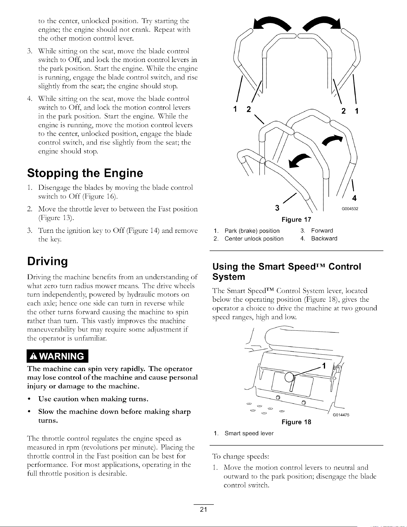
Stopping the Engine
1. Disengage the blades by moving the blade control
switch to Off (Figure i6).
2. Move the throttle lever to between the Fast position
(Figure i3).
3. Turn the ignition key to Off (Figure 14) and remove
the ke>
J 4
G004532
Figure 17
1. Park (brake) position 3. Forward
2. Center unlock position 4. Backward
Driving
Driving the machine benefits from an understanding of
what zero turn radius mower means. The drive wheels
turn independentl B powered by hydraulic motors on
each axle; hence one side can turn in reverse while
the other turns forward causing the machine to spin
rather than turn. This vastly improves the machine
maneuverability but may require some adjustment if
the operator is unfamiliar.
Using the Smart Speed TM Control
System
The Smart Speed TM Control System lever, located
below the operating position (Figure 18), gives the
operator a choice to drive the machine at two ground
speed ranges, high and low.
The machine can spin very rapidly. The operator
may lose control of the machine and cause personal
injury or damage to the machine.
• Use caution when making turns.
• Slow the machine down before making sharp
turns.
The throttle control regulates the engine speed as
measured in rpm (revolutions per minute). Placing the
throttle control in the Fast position can be best for
performance. For most applications, operating in the
full throttle position is desirable.
1. Smart speed lever
Figure 18
G014475
_fb change speeds:
1. Move the motion control levers to neutral and
outward to the park position; disengage the blade
control switch.
21
Removingyour handsfrom the motion control
leverswhile the machine is in motion canresult
in a loss of control causingharm to you or
bystanders.
Alwaysstopthe machine and movethe motion
control leversto the park position before
adjustingthe SmartSpeedTM Control System.
2. Adjust the lever to the desired position.
Forward
1. Move the levers to the center, unlocked position.
2. To go forward, slowly push the motion control
levers forward (Figure 17).
) G008953
Figure 20
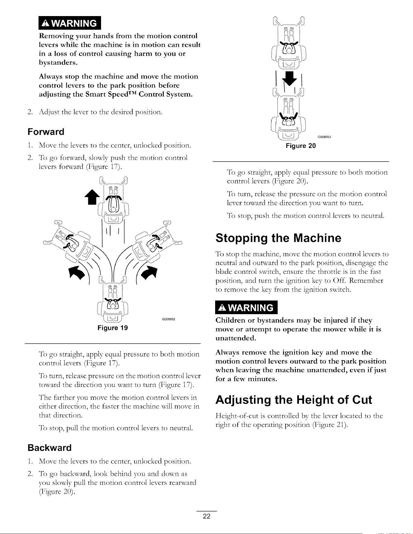
To go straight, apply equal pressure to both motion
control levers (Figure 20).
To turn, release the pressure on the motion control
lever toward the direction you want to turn.
To stop, push the motion control levers to neutral
Stopping the Machine
To stop the machine, move the motion control levers to
neutral and outward to the park position, disengage the
blade control switch, ensure the throttle is in the fast
position, and turn the ignition key to Oft. Remember
to remove the key from the ignition switch.
Figure 19
To go straight, apply equal pressure to both motion
control levers (Figure i7).
To turn, release pressure on the motion control lever
toward the direction you want to turn (Figure i7).
The farther you move the motion control levers in
either direction, the faster the machine will move in
that direction.
To stop, Dull the motion control levers to neutral
Children or bystanders may be injured if they
move or attempt to operate the mower while it is
unattended.
Always remove the ignition key and move the
motion control levers outward to the park position
when leaving the machine unattended, even if just
for a few minutes.
Adjusting the Height of Cut
Height-of-cut is controlled by the lever located to the
right of the operating position (Figure 2i).
Backward
.
2.
Move the levers to the center, unlocked position.
To go backward, look behind you and down as
you slowly pull the motion control levers rearward
(Figure 20).
22
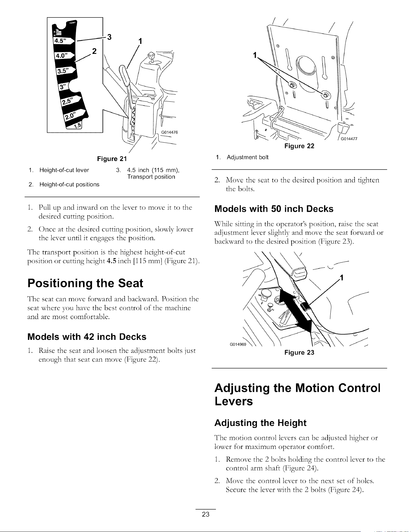
G014476
Figure 21
1. Height-of-cut lever 3. 4.5 inch (115 mm),
Transport position
2. Height-of-cut positions
/
o!
1. Adjustment bolt
Figure 22
G014477
2. Move the seat to the desired position and tighten
the bolts.
.
.
Pull up and inward on the lever to move it to the
desired cutting position.
Once at the desired cutting position, slowly lower
the lever until it engages the position.
The transport position is the highest height-of-cut
position or cutting height 4.5 inch [i 15 ram] (Figure 2i).
Positioning the Seat
The seat can move forward and backward. Position the
seat where you have the best control of the machine
and are most comfortable.
Models with 42 inch Decks
1. Raise the seat and loosen the adjustment bolts just
enough that seat can move (Figure 22).
Models with 50 inch Decks
While sitting in the operator's position, raise the seat
adjustment lever slightly and move the seat forward or
backward to the desired position (Figure 23).
\
G014969
Figure 23
Adjusting the Motion Control
Levers
Adjusting the Height
The motion control levers can be adjusted higher or
lower for maximum operator comfort.
1. Remove the 2 bolts holding the control lever to the
control arm shaft (Figure 24).
2. Move the control lever to the next set of holes.
Secure the lever with the 2 bolts (Figure 24).
23
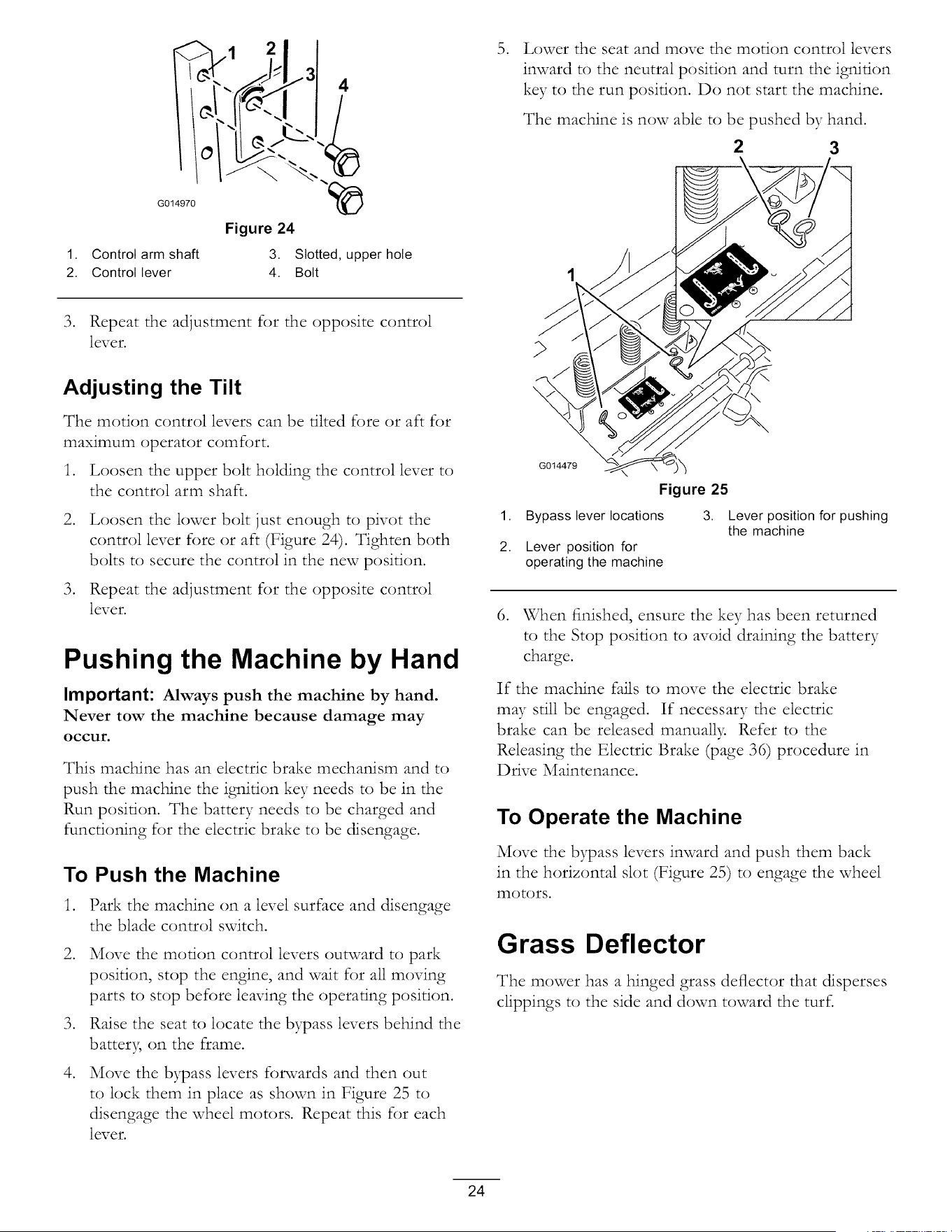
G014970
1. Control arm shaft
2. Control lever
Figure 24
3. Slotted, upper hole
4. Bolt
3. Repeat the adjustment for the opposite control
lever.
Adjusting the Tilt
The motion control levers can be tilted fore or aft for
maximum operator comfort.
1. Loosen the upper bolt holding the control lever to
the control arm shaft.
.
.
Loosen the lower bolt just enough to pivot the
control lever fore or aft (Figure 24). Tighten both
bolts to secure the control in the new position.
Repeat the adjustment for the opposite control
lever.
Pushing the Machine by Hand
Important: Always push the machine by hand.
Never tow the machine because damage may
occur.
This machine has an electric brake mechanism and to
push the machine the ignition key needs to be in the
Run position. The battery needs to be charged and
functioning for the electric brake to be disengage.
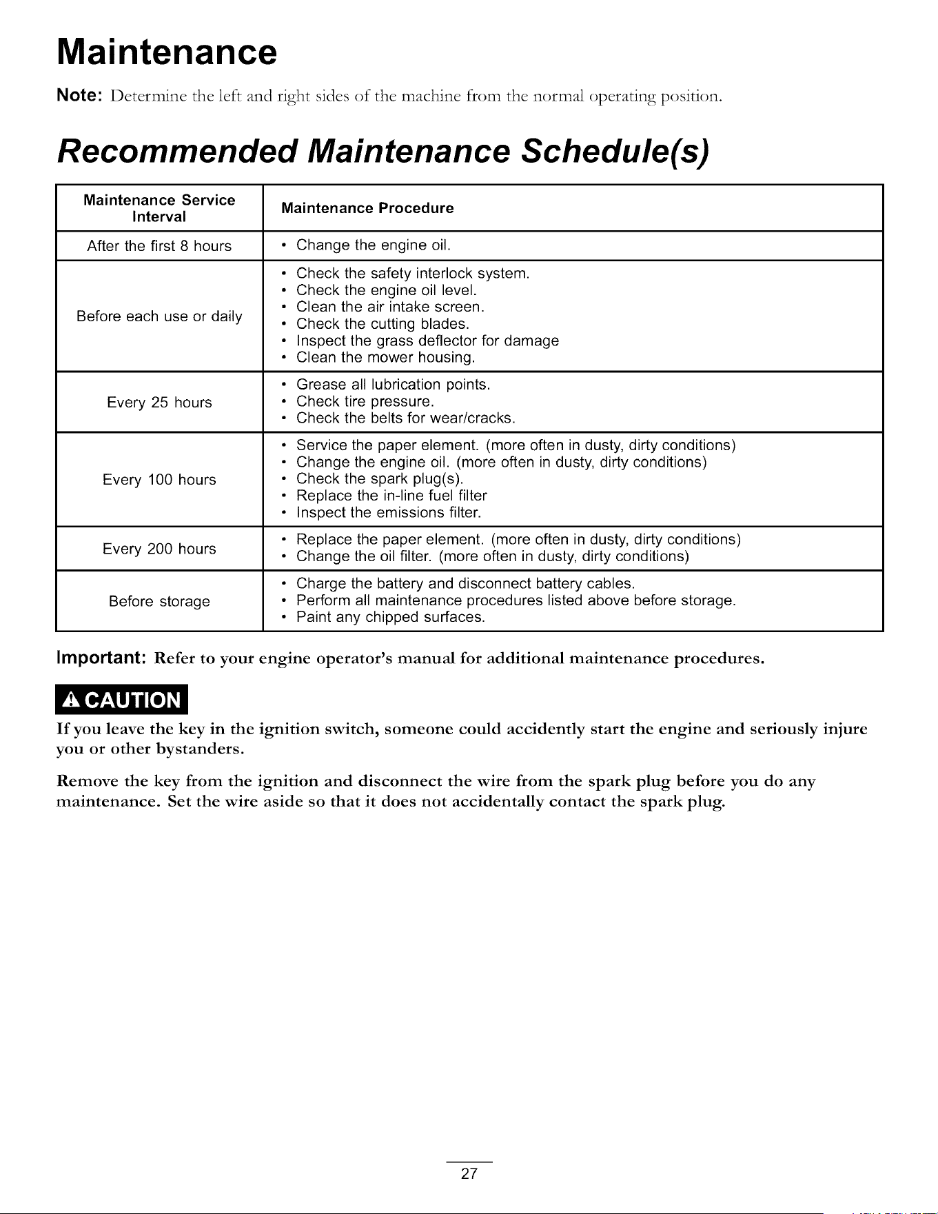
To Push the Machine
1. Park the machine on a level surface and disengage
the blade control switch.
2. Move the motion control levers outward to park
position, stop the engine, and wait for all moving
parts to stop before leaving the operating position.
3. Raise the seat to locate the bypass levers behind the
batter}; on the frame.
.
Move the bypass levers forwards and then out
to lock them in place as shown in Figure 25 to
disengage the wheel motors. Repeat this for each
lever.
. Lower the scat and move the motion control levers
inward to the neutral position and turn the ignition
key to the run position. Do not start the machine.
The machine is now able to be pushed by hand.
2 3
1,
2.
G014479
Figure 25
Bypass lever locations 3. Lever position for pushing
the machine
Lever position for
operating the machine
6. When finished, ensure the key has been returned
to the Stop position to avoid draining the battery
charge.
If the machine fails to move the electric brake
may still be engaged. If necessary the electric
brake can be released manually. Refer to the
Releasing the Electric Brake (page 36) procedure in
Drive Maintenance.
To Operate the Machine
Move the bypass levers inward and push them back
in the horizontal slot (Figure 25) to engage the wheel
motors.
Grass Deflector
The mower has a hinged grass deflector that disperses
clippings to the side and down toward the turf.
24

Without the grass deflector, discharge cover, or
complete grass catcher assembly mounted in
place, you and others are exposed to blade contact
and thrown debris. Contact with rotating mower
blade(s) and thrown debris will cause injury or
death.
Never remove the grass deflector from the
mower because the grass deflector routes
material down toward the turf. If the
grass deflector is ever damaged, replace it
immediately.
Never put your hands or feet under the mower.
Never try to clear discharge area or mower
blades unless you move the blade control switch
to Off and rotate the ignition key to Off. Also
remove the key and pull the wire off the spark
plug(s).
Operating Tips
Fast Throttle Setting
For best mowing and maximum air circulation, operate
the engine at the Fast position. Air is required to
thoroughly cut grass clippings, so do not set the
height-of-cut so low as to totally surround the mower
by uncut grass. Always try to have one side of the
mower free from uncut grass, which allows air to be
drawn into the mower.
Using the Smart Speed TM Control
System
The Smart Speed TM Control System lever, located
below the operating position, gives the operator a
choice to drive the machine at two speed ranges, high
and low. An operator can benefit from the lower speed
setting when maneuvering the machine in tight spaces
or operating around delicate landscapes. The low
setting can also be used to operate the machine at a
high throttle setting and blade speed while still being
able to reduce ground speed to increase quality of cut.
Cutting a Lawn for the First Time
Cut grass slightly longer than normal to ensure that the
cutting height of the mower does not scalp any uneven
ground. However, the cutting height used in the past is
generally the best one to use. When cutting grass longer
than six inches tall, you may want to cut the lawn twice
to ensure an acceptable quality of cut.
Cut 1/3 of the Grass Blade
It is best to cut only about i/3 of the grass blade.
Cutting more than that is not recommended unless
grass is sparse, or it is late fall when grass grows more
slowly
Mowing Direction
Alternate mowing direction to keep the grass standing
straight. This also helps disperse clippings which
enhances decomposition and fertilization.
Mow at Correct Intervals
Normall3; mow every fi)ur days. But remember,
grass grows at different rates at different times. So
to maintain the same cutting height, which is a good
practice, mow more often in early spring. As the grass
growth rate slows in mid summer, mow less frequently.
If you cannot mow for an extended period, first mow
at a high cutting height; then mow again two days later
at a lower height setting.
Avoid Cutting Too Low
If the cutting width of the mower is wider than the
mower you previously used, raise the cutting height to
ensure that uneven turf is not cut too short.
Long Grass
If the grass is ever allowed to grow slightly longer than
normal, or if it contains a high degree of moisture, raise
the cutting height higher than usual and cut the grass at
this setting. Then cut the grass again using the lower,
normal setting.
When Stopping
If the machine's forward motion must be stopped while
mowing, a clump of grass clippings may drop onto your
lawn. To avoid this, move onto a previously cut area
with the blades engaged.
Keep the Underside of the Mower
Clean
Clean clippings and dirt from the underside of the
mower after each use. If grass and dirt build up inside
the mower, cutting quality will eventually become
unsatisfactor}.
Blade Maintenance
Maintain a sharp blade throughout the cutting season
because a sharp blade cuts cleanly without tearing or
25

shredding the grass blades. Tearing and shredding turns
grass brown at the edges, which slows growth and
increases the chance of disease. Check the cutter blades
daily for sharpness, and for aW wear or damage. File
down aW nicks and sharpen the blades as necessar> If
a blade is damaged or worn, replace it immediately with
a genuine _l-bro replacement blade.
26
Maintenance
Note: Determine the left and right sides of the machine from the normal operating position.
Recommended Maintenance Schedule(s)
Maintenance Service
Maintenance Procedure
Interval
After the first 8 hours • Change the engine oil.
Before each use or daily
Every 25 hours
Every 100 hours
• Check the safety interlock system.
° Check the engine oil level.
• Clean the air intake screen.
° Check the cutting blades.
• Inspect the grass deflector for damage
° Clean the mower housing.
• Grease all lubrication points.
° Check tire pressure.
° Check the belts for wear/cracks.
• Service the paper element. (more often in dusty, dirty conditions)
• Change the engine oil. (more often in dusty, dirty conditions)
° Check the spark plug(s).
° Replace the in-line fuel filter
° Inspect the emissions filter.
° Replace the paper element. (more often in dusty, dirty conditions)
Every 200 hours
• Change the oil filter. (more often in dusty, dirty conditions)
° Charge the battery and disconnect battery cables.
Before storage • Perform all maintenance procedures listed above before storage.
• Paint any chipped surfaces.
Important: Refer to your engine operator's manual for additional maintenance procedures.
If you leave the key in the ignition switch, someone could accidently start the engine and seriously injure
you or other bystanders.
Remove the key from the ignition and disconnect the wire from the spark plug before you do any
maintenance. Set the wire aside so that it does not accidentally contact the spark plug.
27
Premaintenance
Procedures
Raising the Seat
Make sure the motion control levers are locked in the
park position. Lift the seat forward.
The following components can be accessed by raising
the seat:
• Serial plate
• Service decal
• Seat adjustment bolts
• Fuel filter
• Battery and battery cables
Lubrication
Greasing the Bearings
Service Interval: Every 25 hours--Grease all
lubrication points.
Grease Type: No. 2 General Purpose Lithium Base
Grease
1. Park the machine on a level surface and disengage
the blade control switch.
.
.
Move the motion control levers outward to the
park position, stop the engine, remove the ke3, and
wait for all moving parts to stop before leaving the
operating position.
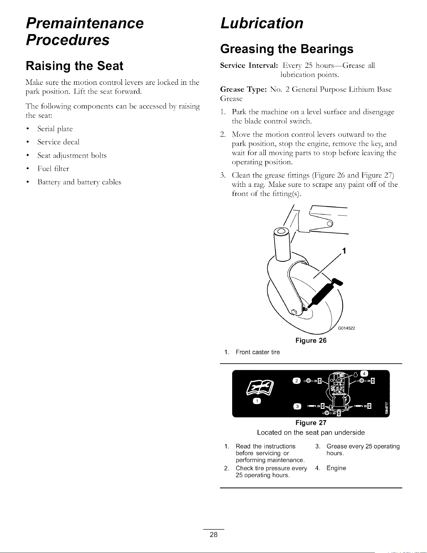
Clean the grease fittings (Figure 26 and Figure 27)
with a rag. Make sure to scrape any paint off of the
front of the fitting(s).
1. Front caster tire
Figure 26
G014522
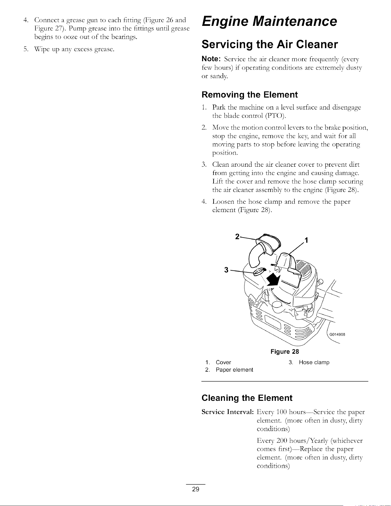
Figure 27
Located on the seat pan underside
1. Read the instructions
before servicing or
performing maintenance.
2. Check tire pressure every
25 operating hours.
3. Grease every 25 operating
hours.
4. Engine
28
.
Connect a grease gun to each fitting (Figure 26 and
Figure 27). Pump grease into the fittings until grease
begins to ooze out of the bearings.
5. Wipe up any excess grease.
Engine Maintenance
Servicing the Air Cleaner
Note: Service the air cleaner more frequently (every
few hours) if operating conditions are extremely dusty
or sandy.
Removing the Element
1. Park the machine on a level surface and disengage
the blade control (PTO).
.
Move the motion control levers to the brake position,
stop the engine, remove the ke5 and wait for all
moving parts to stop before leaving the operating
position.
.
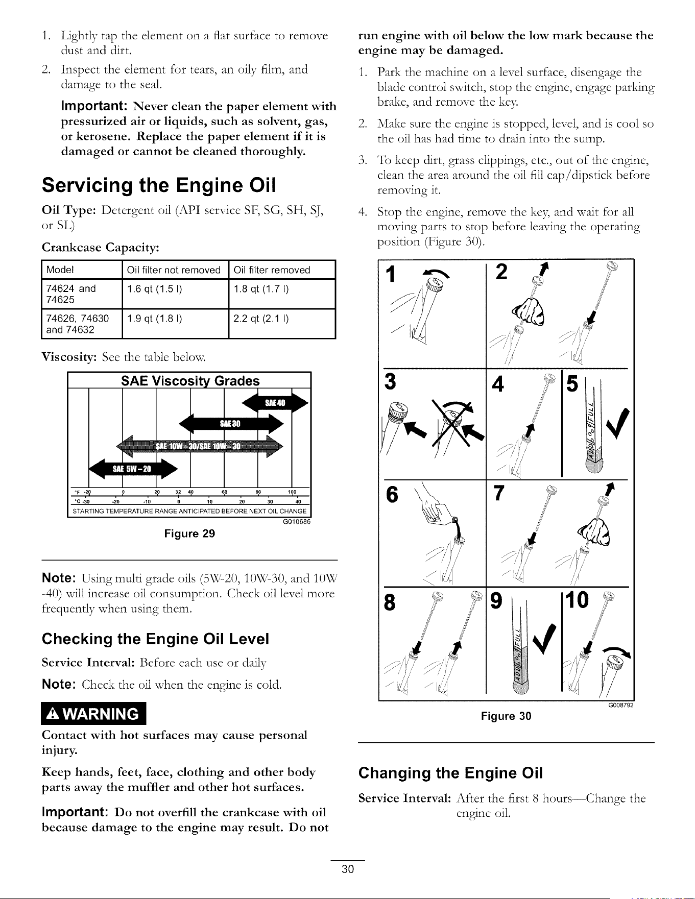
Clean around the air cleaner cover to prevent dirt
from getting into the engine and causing damage.
Lift the cover and remove the hose clamp securing
the air cleaner assembly to the engine (Figure 28).
4. Loosen the hose clamp and remove the paper
element (Figure 28).
3014908
1. Cover
2. Paper element
Figure 28
3. Hose clamp
Cleaning the Element
Service Interval: Every i00 hours--Service the paper
element. (more often in dust 5 dirty
conditions)
Every 200 hours/Yearly (whichever
comes first)--Rcplace the paper
element. (more often in dust 5 dirty
conditions)
29
.
.
Lightly tap the element on a flat surface to remove
dust and dirt.
Inspect the element for tears, an oily film, and
damage to the seal.
Important: Never clean the paper element with
pressurized air or liquids, such as solvent, gas,
or kerosene. Replace the paper element if it is
damaged or cannot be cleaned thoroughly.
Servicing the Engine Oil
Oil Type: Detergent oil (API service SF, SG, SH, SJ,
or SL)
Crankcase Capacity:
Model Oil filter not removed Oil filter removed
74624 and 1.6 qt (1.5 1) 1.8 qt (1.7 I)
74625
74626, 74630 1.9 qt (1.8 I) 2.2 qt (2.1 I)
and 74632
Viscosity: See the table below.
SAE Viscosity Grades _"
°F *20 0 20 32 40 60 80 100
,= , i , i / i , = , = , = ,
°C *30 -20 -10 0 10 20 30 40
STARTING TEMPERATURE RANGE ANTICIPATED BEFORE NEXT OIL CHANGE
G010686
Figure 29
Note: Using multi grade oils (5W-20, 10W-30, and I0W
-40) will increase oil consumption. Check oil level more
frequently when using them.
Checking the Engine Oil Level
Service Interval: Before each use or daily
Note: Check the oil when the engine is cold.
Contact with hot surfaces may cause personal
injury.
Keep hands, feet, face, clothing and other body
parts away the muffler and other hot surfaces.
Important: Do not overfill the crankcase with oil
because damage to the engine may result. Do not
run engine with oil below the low mark because the
engine may be damaged.
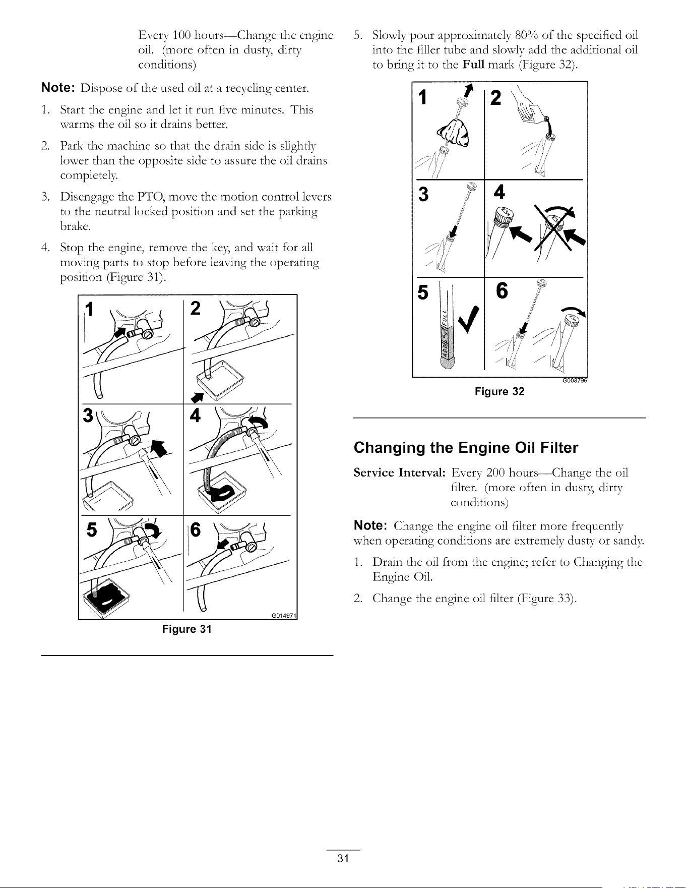
.
.
.
.
Park the machine on a level surface, disengage the
blade control switch, stop the engine, engage parking
brake, and remove the key.
Make sure the engine is stopped, level, and is cool so
the oil has had rime to drain into the sump.
To keep dirt, grass clippings, etc., out of the engine,
clean the area around the oil fill cap/dipstick before
removing it.
Stop the engine, remove the key, and wait for all
moving parts to stop before leaving the operating
position (Figure 30).
3
6
8
2
/ ,,,{
i /
9
¢
10
Figure 30
G008792
Changing the Engine Oil
Service Interval: After the first 8 hours--Change the
engine oil.
3O
Every 100 hours--Change the engine
oil. (more often in dusty, dirty
conditions)
Note: Dispose of the used oil at a recycling center.
1. Start the engine and let it run five minutes. This
warms the oil so it drains better.
.
.
Park the machine so that the drain side is slightly
lower than the opposite side to assure the oil drains
completely.
Disengage the PTO, move the motion control levers
to the neutral locked position and set the parking
brake.
4. Stop the engine, remove the key, and wait for all
moving parts to stop before leaving the operating
position (Figure 31).
Figure 31
G01497_
.
Slowly pour approximately 80% of the specified oil
into the filler tube and slowly add the additional oil
to bring it to the Full mark (Figure 32).
1
3
5
m
2
4
6
Figure 32
G008796
Changing the Engine Oil Filter
Service Interval: Every 200 hours--Change the oil
filter. (more often in dusty, dirty
conditions)
Note: Change the engine oil filter more frequently
when operating conditions are extremely dusty or sandy.
1. Drain the oil from the engine; refer to (;hanging the
Engine Oil.
2. Change the engine oil filter (Figure 33).
31
3
2
6
6_..
Figure 33
3/4
G008748
.
Note: Ensure the oil filter gasket touches the engine
and then an extra 3/4 turn is completed.
Fill the crankcase with the proper type of new oil;
refer to (;hanging the Oil.
Servicing the Spark Plug
Service Interval: Every i00 hours--Check the spark
plug(s).
Make sure the air gap between the center and side
electrodes is correct before installing the spark plug.
Use a spark plug wrench for removing and installing
the spark plug(s) and a gapping tool/feeler gauge to
check and adjust the air gap. Install a new spark plug(s)
if necessar>
Type: NGK BPR4ES (or equivalent)
Air Gap: 0.030 inch (0.76 ram)
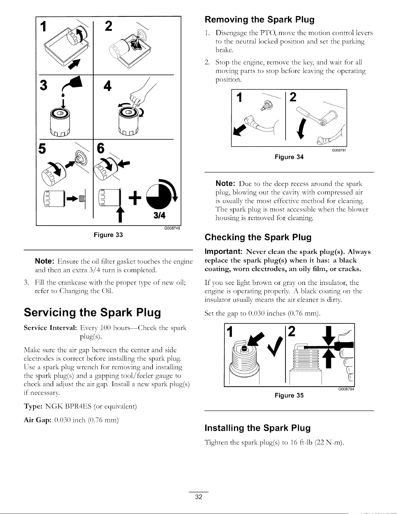
Removing the Spark Plug
1. Disengage the PTO, move the motion control levers
to the neutral locked position and set the parking
brake.
2. Stop the engine, remove the key, and wait for all
moving parts to stop before leaving the operating
position.
G008791
Figure 34
Note: Due to the deep recess around the spark
plug, blowing out the cavity with compressed air
is usually the most effective method for cleaning.
The spark plug is most accessible when the blower
housing is removed for cleaning.
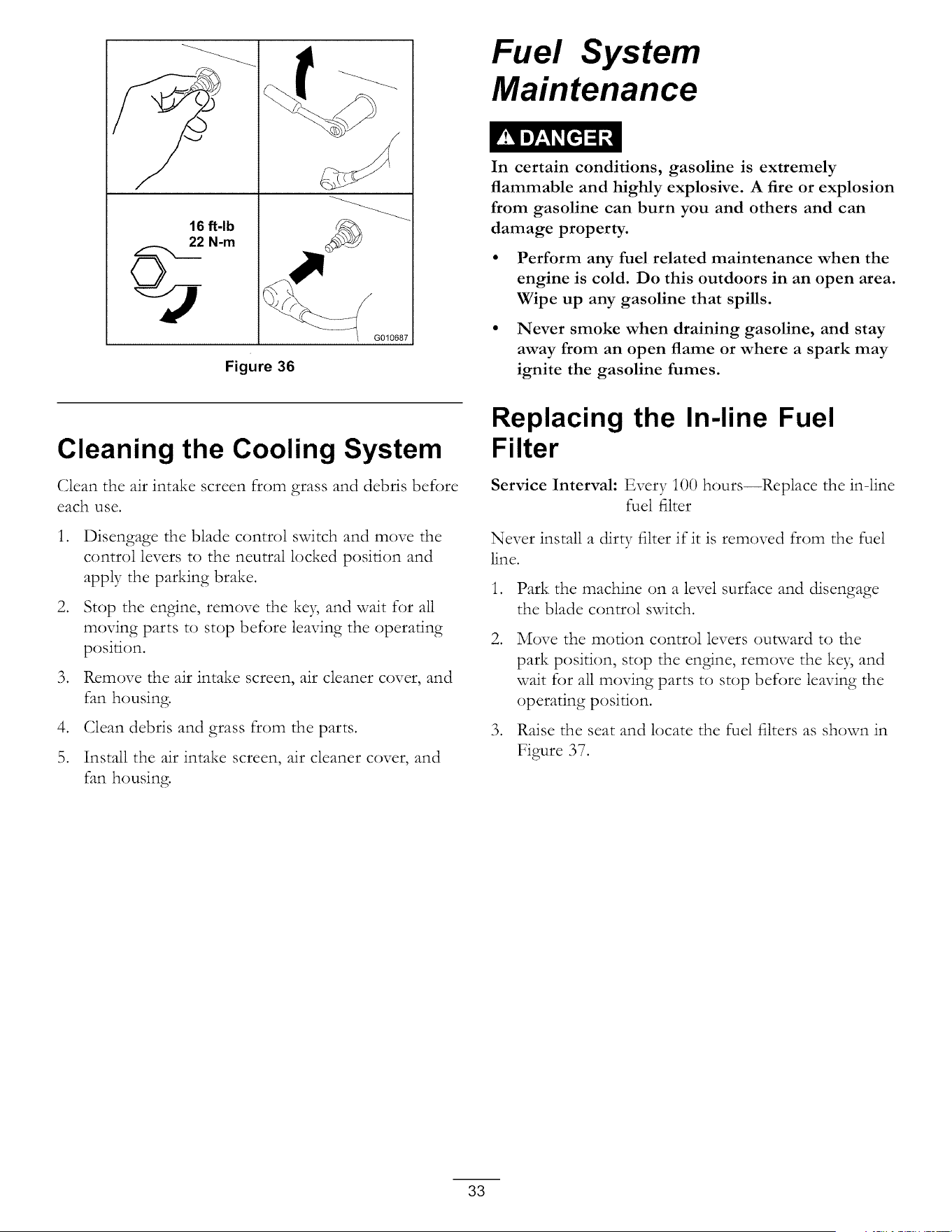
Checking the Spark Plug
Important: Never clean the spark plug(s). Always
replace the spark plug(s) when it has: a black
coating, worn electrodes, an oily film, or cracks.
If you see light brown or gray on the insulator, the
engine is operating properly. A black coating on the
insulator usually means the air cleaner is dirty.
Set the gap to 0.030 inches (0.76 ram).
2
Figure 35
G008794
Installing the Spark Plug
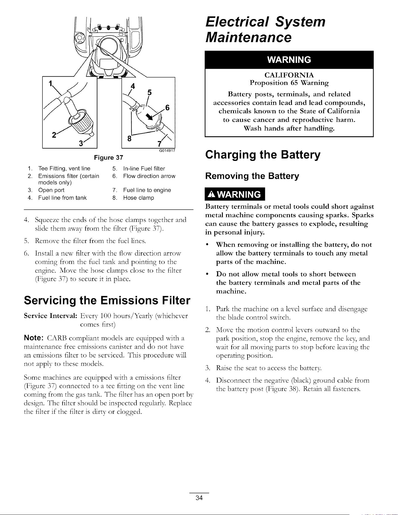
Tighten the spark plug(s) to 16 fr-lb (22 N-m).
32
16 ft-lb
_/ 22 N-m
G010687
Figure 36
Fuel System
Maintenance
In certain conditions, gasoline is extremely
flammable and highly explosive. A fire or explosion
from gasoline can burn you and others and can
damage property.
• Perform any fuel related maintenance when the
engine is cold. Do this outdoors in an open area.
Wipe up any gasoline that spills.
• Never smoke when draining gasoline, and stay
away from an open flame or where a spark may
ignite the gasoline fumes.
Cleaning the Cooling System
(;lean the air intake screen from grass and debris before
each use.
.
.
.
.
5.
Disengage the blade control switch and move the
control levers to the neutral locked position and
apply the parking brake.
Stop the engine, remove the key, and wait for all
moving parts to stop before leaving the operating
position.
Remove the air intake screen, air cleaner cover, and
fan housing.
(;lean debris and grass from the parts.
Install the air intake screen, air cleaner cover, and
fan housing.
Replacing the In-line Fuel
Filter
Service Interval: Every i00 hours--Replace the in-line
fuel filter
Never install a dirty filter if it is removed from the fuel
line.
1. Park the machine on a level surface and disengage
the blade control switch.
.
.
Move the motion control levers outward to the
park position, stop the engine, remove the key and
wait for all moving parts to stop before leaving the
operating position.
Raise the seat and locate the fuel filters as shown in
Figure 37.
33
Electrical System
Maintenance
2
8
Figure 37
5
7 i
G014917
1. Tee Fitting, vent line 5. In-line Fuel filter
2. Emissions filter (certain 6. Flow direction arrow
models only)
3. Open port 7. Fuel line to engine
4. Fuel line from tank 8. Hose clamp
.
.
6.
Squeeze the ends of the hose clamps together and
slide them away from the filter (Figure 37).
Remove the filter from the fuel lines.
Install a new filter with the flow direction arrow
coming from the fuel tank and pointing to the
engine. Move the hose clamps close to the filter
(Figure 37) to secure it in place.
Servicing the Emissions Filter
Service Interval: Every i00 hours/Yearly (whichever
comes first)
Note: CARB compliant models are equipped with a
maintenance free emissions canister and do not have
an emissions filter to be serviced. This procedure will
not apply to these models.
Some machines are equipped with a emissions filter
(Figure 37) connected to a tee fitting on the vent line
coming from the gas tank. The filter has an ()pen port by
design. The filter should be inspected regularly Replace
the filter if the filter is dirty or clogged.
CALIFORNIA
Proposition 65 Warning
Battery posts, terminals, and related
accessories contain lead and lead compounds,
chemicals known to the State of California
to cause cancer and reproductive harm.
Wash hands after handling.
Charging the Battery
Removing the Battery
Battery terminals or metal tools could short against
metal machine components causing sparks. Sparks
can cause the battery gasses to explode, resulting
in personal injury.
• When removing or installing the battery, do not
allow the battery terminals to touch any metal
parts of the machine.
• Do not allow metal tools to short between
the battery terminals and metal parts of the
machine.
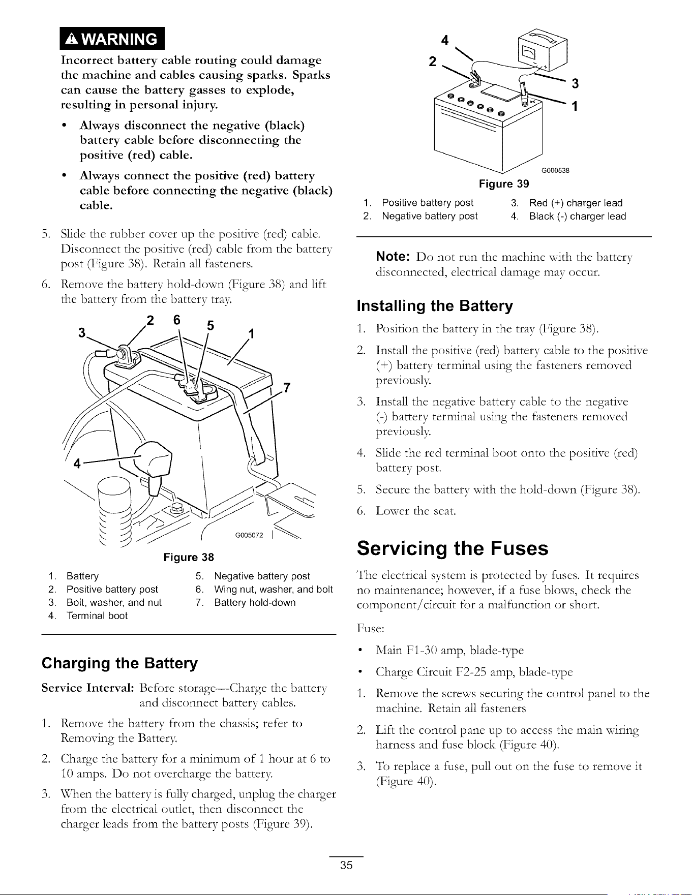
.
.
.
4.
Park the machine on a level surface and disengage
the blade control switch.
Move the motion control levers outward to the
park position, stop the engine, remove the ke), and
wait for all moving parts to stop before leaving the
operating position.
Raise the seat to access the battery.
Disconnect the negative (black) ground cable from
the battery post (Figure 38). Retain all fasteners.
34
Incorrect battery cablerouting could damage
themachine and cablescausingsparks. Sparks
can causethe battery gassesto explode,
resulting in personalinjury.
• Mways disconnect the negative (black)
battery cable before disconnecting the
positive (red) cable.
• Mways connect the positive (red) battery
cable before connecting the negative (black)
cable.
5. Slide the rubber cover up the positive (red) cable.
Disconnect the positNe (red) cable from the battery
post (Figure 38). Retain all fasteners.
6. Rcmove the battery hold-down (Figure 38) and lift
the battery from the battery tra>
2 6
5
G005072
Figure 38
1. Battery
2. Positive battery post
3. Bolt, washer, and nut
4. Terminal boot
5. Negative battery post
6. Wing nut, washer, and bolt
7. Battery hold-down
Charging the Battery
Service Interval: Before storage--Charge the battery
and disconnect battery cables.
1. Remove the battery from the chassis; refer to
Removing the Batter>
2. Charge the battery for a minimum of 1 hour at 6 to
1() amps. Do not overcharge the batter>
3. When the battery is fully charged, unplug the charger
from the electrical outlet, then disconnect the
charger leads from the battery posts (Figure 39).
4
2
3
1
G000538
Figure 39
1. Positive battery post 3. Red (+) charger lead
2. Negative battery post 4. Black (-) charger lead
Note: Do not run the machine with the battery
disconnected, electrical damage may occur.
Installing the Battery
1. Position the battery in the tray (Figure 38).
2. Install the positive (red) battery cable to the positive
(÷) battery terminal using the fasteners removed
previousl>
3. Install the negatNe battery cable to the negative
(=) battery terminal using the fasteners removed
previousl>
4. Slide the red terminal boot onto the positive (red)
battery post.
5. Secure the battery with the hold=down (Figure 38).
6. Lower the seat.
Servicing the Fuses
The electrical system is protected by fuses. It requires
no maintenance; however, if a fuse blows, check the
component/circuit for a malfunction or short.
Fuse:
• Main FI40 amp, blade=type
• Charge Circuit F2-25 amp, blade=type
1. Remove the screws securing the control panel to the
machine. Retain all fasteners
.
.
Lift the control pane up to access the main wiring
harness and fuse block (Figure 40).
_l-breplace a fuse, pull out on the fuse to remove it
(Figure 40).
35
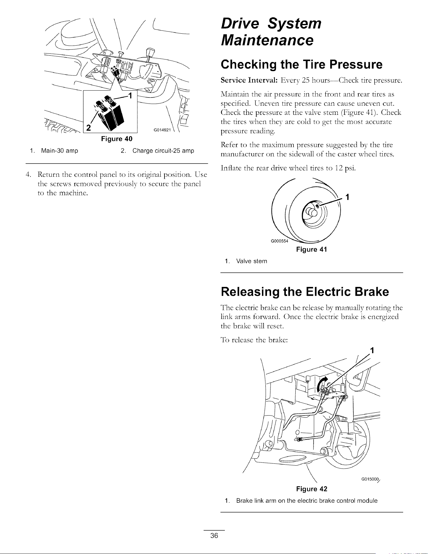
1,
.
/
Figure 40
Main-30 amp
2. Charge circuit-25 amp
Return the control panel to its original position. Use
the screws removed previously to secure the panel
to the machine.
Drive System
Maintenance
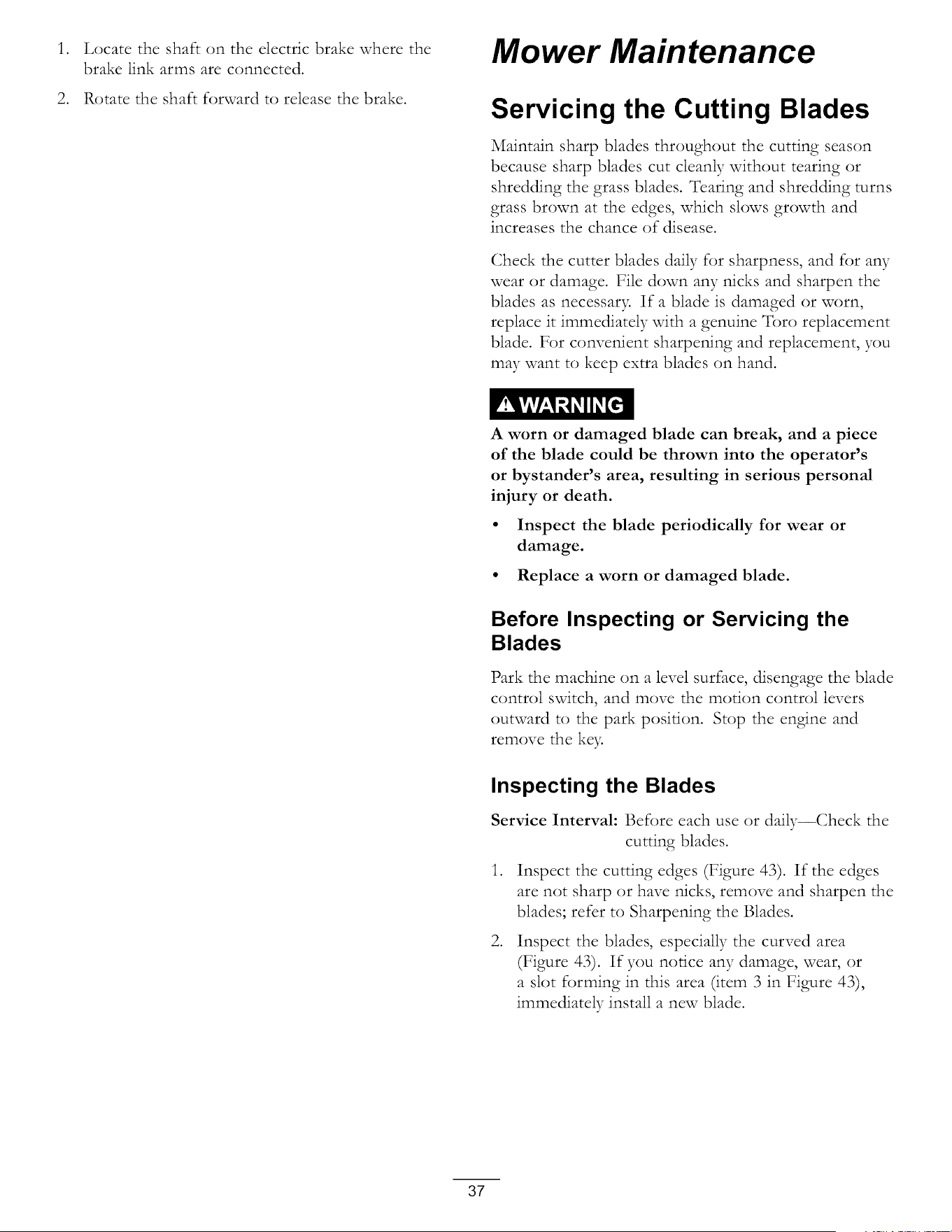
Checking the Tire Pressure
Service Interval: Every 25 hours--Check tire pressure.
Maintain the air pressure in the front and rear tires as
specified. Uneven tire pressure can cause uneven cut.
Check the pressure at the vane stem (Figure 41). Check
the tires when they are cold to get the most accurate
pressure reading.
Refer to the maximum pressure suggested by the fire
manufacturer on the sidewall of the caster wheel tires.
Inflate the rear drive wheel fires to 12 psi.
G000554
Figure 41
1. Valve stem
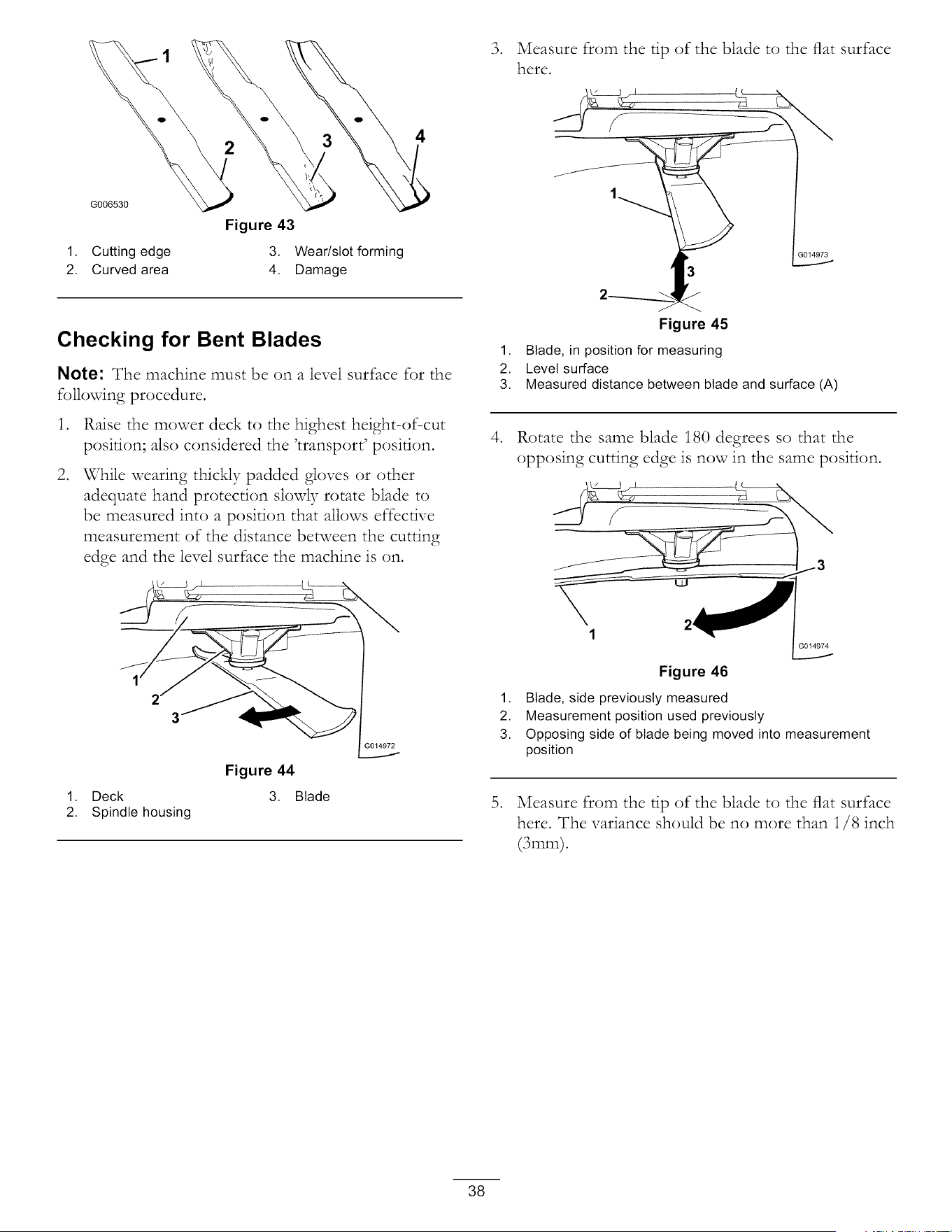
Releasing the Electric Brake
The electric brake can be release by manually rotating the
link arms forward. Once the electric brake is energized
the brake will reset.
To release the brake:
1,
G015000/
Figure 42
Brake link arm on the electric brake control module
36
. Locate the shaft on the electric brake where the
brake link arms are connected.
2. Rotate the shaft forward to release the brake.
Mower Maintenance
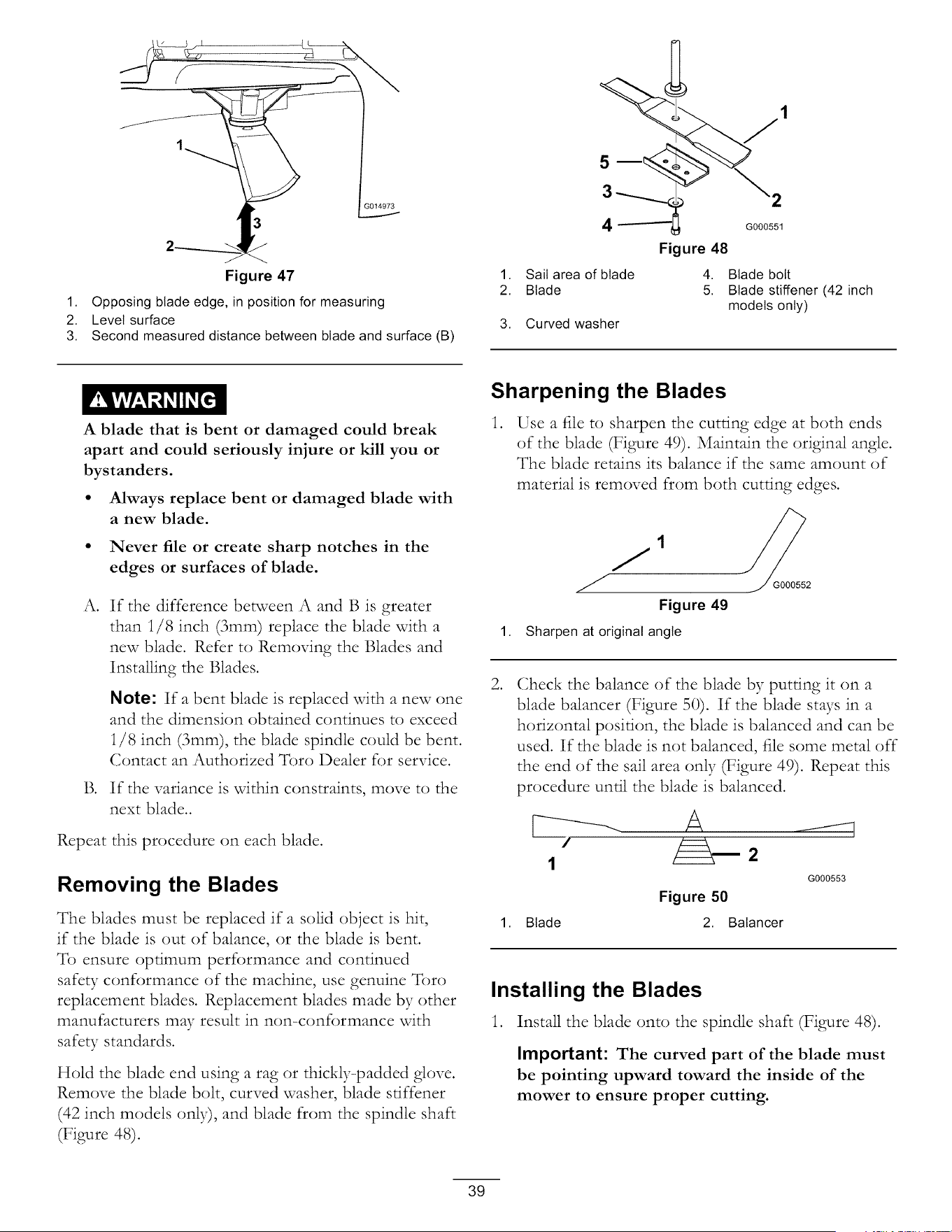
Servicing the Cutting Blades
Maintain sharp blades throughout the cutting season
because sharp blades cut cleanly without tearing or
shredding the grass blades. Tearing and shredding turns
grass brown at the edges, which slows growth and
increases the chance of disease.
Check the cutter blades daily for sharpness, and for a W
wear or damage. File down any nicks and sharpen the
blades as necessar> If a blade is damaged or worn,
replace it immediately with a genuine Toro replacement
blade. For convenient sharpening and replacement, you
may want to keep extra blades on hand.
A worn or damaged blade can break, and a piece
of the blade could be thrown into the operator's
or bystander's area, resulting in serious personal
injury or death.
• Inspect the blade periodically for wear or
damage.
• Replace a worn or damaged blade.
Before Inspecting or Servicing the
Blades
Park the machine on a level surface, disengage the blade
control switch, and move the motion control levers
outward to the park position. Stop the engine and
remove the ke>
Inspecting the Blades
Service Interval: Before each use or daily--Check the
cutting blades.
.
.
Inspect the cutting edges (Figure 43). If the edges
are not sharp or have nicks, remove and sharpen the
blades; refer to Sharpening the Blades.
Inspect the blades, especially the curved area
(Figure 43). If you notice any damage, wear, or
a slot forming in this area (item 3 in Figure 43),
immediately install a new blade.
37
G006530
Figure 43
1. Cutting edge 3. Wear/slot forming
2. Curved area 4. Damage
4
3. Measure from the tip of the blade to the flat surface
here.
}014973
Checking for Bent Blades
Rote: The machine must be on a level surface for the
following procedure.
.
.
Raise the mower deck to the highest height-of-cut
position; also considered the 'transport' position.
While wearing thickly padded gloves or other
adequate hand protection slowly rotate blade to
be measured into a position that allows effective
measurement of the distance between the cutting
edge and the level surface the machine is on.
1. Deck
2. Spindle housing
Figure 44
3. Blade
G014972
4.
.
Figure 45
1. Blade, in position for measuring
2. Level surface
3. Measured distance between blade and surface (A)
Rotate the same blade i80 degrees so that the
opposing cutting edge is now in the same position.
G014974
Figure 46
1. Blade, side previously measured
2. Measurement position used previously
3. Opposing side of blade being moved into measurement
position
Measure from the tip of the blade to the flat surface
here. The variance should be no more than 1/8 inch
(3mm).
38
G014973
5
3 _2
G000551
Figure 48
Figure 47 1. Sail area of blade 4. Blade bolt
2. Blade 5. Blade stiffener (42 inch
1. Opposing blade edge, in position for measuring models only)
2. Level surface 3. Curved washer
3. Second measured distance between blade and surface (B)
A blade that is bent or damaged could break
apart and could seriously injure or kill you or
bystanders.
• Always replace bent or damaged blade with
a new blade.
• Never file or create sharp notches in the
edges or surfaces of blade.
B.
If the difference between A and B is greater
than i/8 inch (3ram) replace the blade with a
new blade. Refer to Removing the Blades and
Installing the Blades.
Note: If a bent blade is replaced with a new one
and the dimension obtained continues to exceed
1/8 inch (3ram), the blade spindle could be bent.
Contact an Authorized Toro Dealer for service.
If the variance is within constraints, move to the
next blade..
Repeat this procedure on each blade.
Removing the Blades
The blades must be replaced if a solid object is hit,
if the blade is out of balance, or the blade is bent.
To ensure optimum performance and continued
safety conformance of the machine, use genuine Toro
replacement blades. Replacement blades made by other
manufacturers may result in non-conformance with
safety standards.
Hold the blade end using a rag or thickly-padded glove.
Remove the blade bolt, curved washer, blade stiffener
(42 inch models only), and blade from the spindle shaft
(Figure 48).
Sharpening the Blades
.
Use a file to sharpen the cutting edge at both ends
of the blade (Figure 49). Maintain the original angle.
The blade retains its balance if the same amount of
material is removed from both cutting edges.
Figure 49
1. Sharpen at original angle
.
Check the balance of the blade by putting it on a
blade balancer (Figure 50). If the blade stays in a
horizontal position, the blade is balanced and can be
used. If the blade is not balanced, file some metal off
the end of the sail area only (Figure 49). Repeat this
procedure until the blade is balanced.
A _-------q
1
Figure 50
1. Blade 2. Balancer
G000553
Installing the Blades
1. Install the blade onto the spindle shaft (Figure 48).
Important: The curved part of the blade must
be pointing upward toward the inside of the
mower to ensure proper cutting.
39
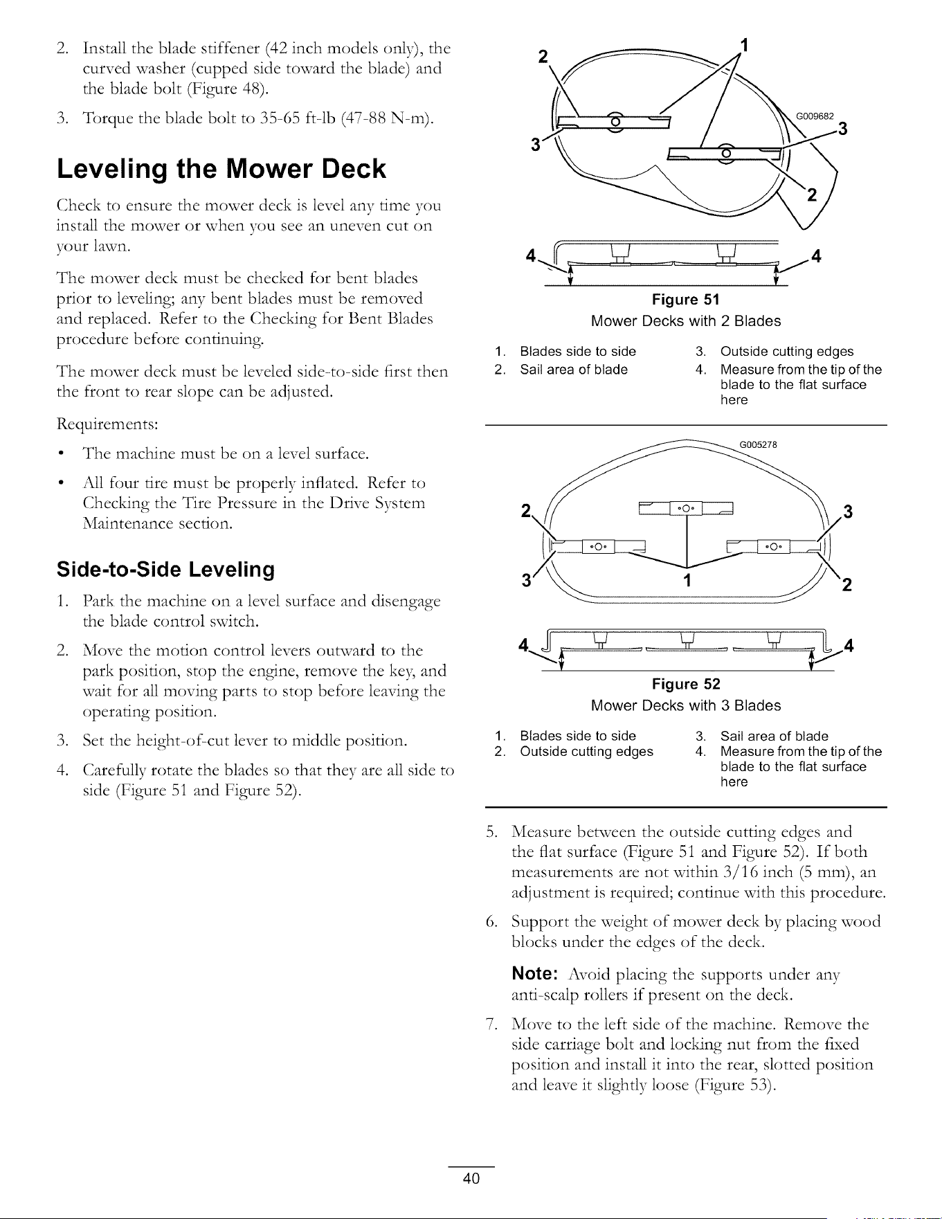
.
Install the blade stiffener (42 inch models only), the
curved washer (cupped side toward the blade) and
the blade bolt (Figure 48).
3. Torque the blade bolt to 35-65 ft-lb (47-88 N-m).
2
G009682
Leveling the Mower Deck
Check to ensure the mower deck is level any time you
install the mower or when you see an uneven cut on
your lawn.
The mower deck must be checked for bent blades
prior to leveling; any bent blades must be removed
and replaced. Refer to the Checking for Bent Blades
procedure before continuing.
The mower deck must be leveled side-to-side first then
the front to rear slope can be adjusted.
Requirements:
• The machine must be on a level surface.
• All four tire must be properly inflated. Refer to
Checking the Tire Pressure in the Drive System
Maintenance section.
Side-to-Side Leveling
1. Park the machine on a level surface and disengage
the blade control switch.
.
.
4.
Move the motion control levers outward to the
park position, stop the engine, remove the ke), and
wait for all moving parts to stop before leaving the
operating position.
Set the height-of-cut lever to middle position.
Carefully rotate the blades so that they are all side to
side (Figure 5i and Figure 52).
.
.
.
Figure 51
Mower Decks with 2 Blades
1. Blades side to side 3. Outside cutting edges
2. Sail area of blade 4. Measure from the tip of the
blade to the flat surface
here
G005278
2\
Figure 52
Mower Decks with 3 Blades
1. Blades side to side 3. Sail area of blade
2. Outside cutting edges 4. Measure from the tip of the
blade to the flat surface
here
Measure between the outside cutting edges and
the flat surface (Figure 5i and Figure 52). If both
measurements are not within 3/i6 inch (5 mm), an
adjustment is required; continue with this procedure.
Support the weight of mower deck by placing wood
blocks under the edges of the deck.
Note: Avoid placing the supports under any
anti-scalp rollers if present on the deck.
Move to the left side of the machine. Remove the
side carriage bolt and locking nut from the fixed
position and install it into the rear, slotted position
and leave it slightly loose (Figure 53).
4O
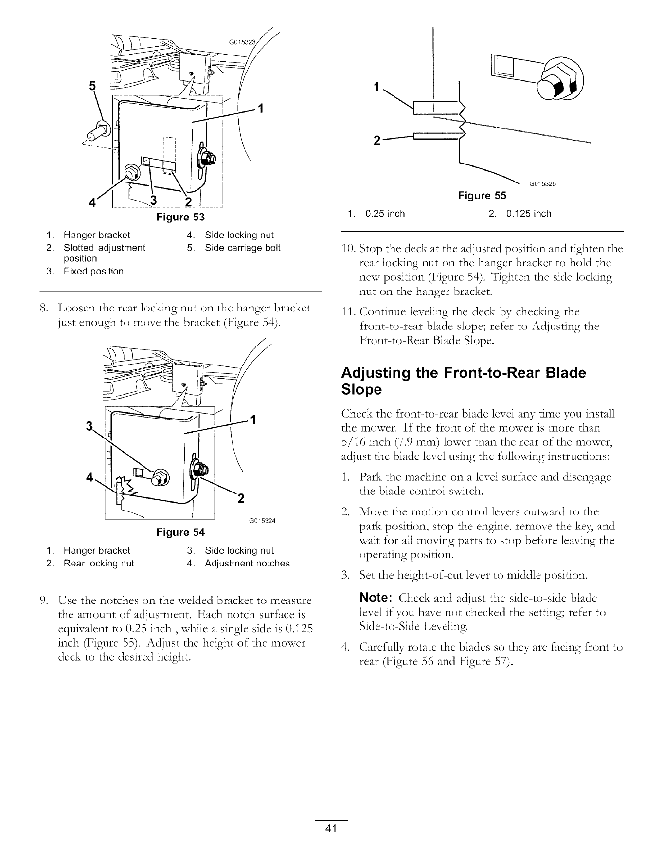
.
.
G015323
----...3
Figure 53
1. Hanger bracket 4. Side locking nut
2. Slotted adjustment 5. Side carriage bolt
position
3. Fixed position
Loosen the rear locking nut on the hanger bracket
just enough to move the bracket (Figure 54).
a.,
4_
Figure 54
G015324
1. Hanger bracket 3. Side locking nut
2. Rear locking nut 4. Adjustment notches
Use the notches on the welded bracket to measure
the amount of adjustment. Each notch surface is
equivalent to 0.25 inch, while a single side is 0.125
inch (Figure 55). Adjust the height of the mower
deck to the desired height.
1,
Figure 55
0.25 inch 2. 0.125 inch
iO.
11.
Stop the deck at the adjusted position and tighten the
rear locldng nut on the hanger bracket to hold the
new position (Figure 54). Tighten the side locking
nut on the hanger bracket.
Continue leveling the deck by checking the
front-to-rear blade slope; refer to Adjusting the
Front-to-Rear Blade Slope.
Adjusting the Front-to-Rear Blade
Slope
Check the front-to-rear blade level any time you install
the mower. If the front of the mower is more than
5/16 inch (7.9 ram) lower than the rear of the mower,
adjust the blade level using the following instructions:
1. Park the machine on a level surface and disengage
the blade control switch.
. Move the motion control levers outward to the
park position, stop the engine, remove the ke), and
wait for all moving parts to stop before leaving the
operating position.
3. Set the height-of-cut lever to middle position.
.
Note: Check and adjust the side-to-side blade
level if you have not checked the setting; refer to
Side-to-Side Leveling.
Carefully rotate the blades so they are facing front to
rear (Figure 56 and Figure 57).
41
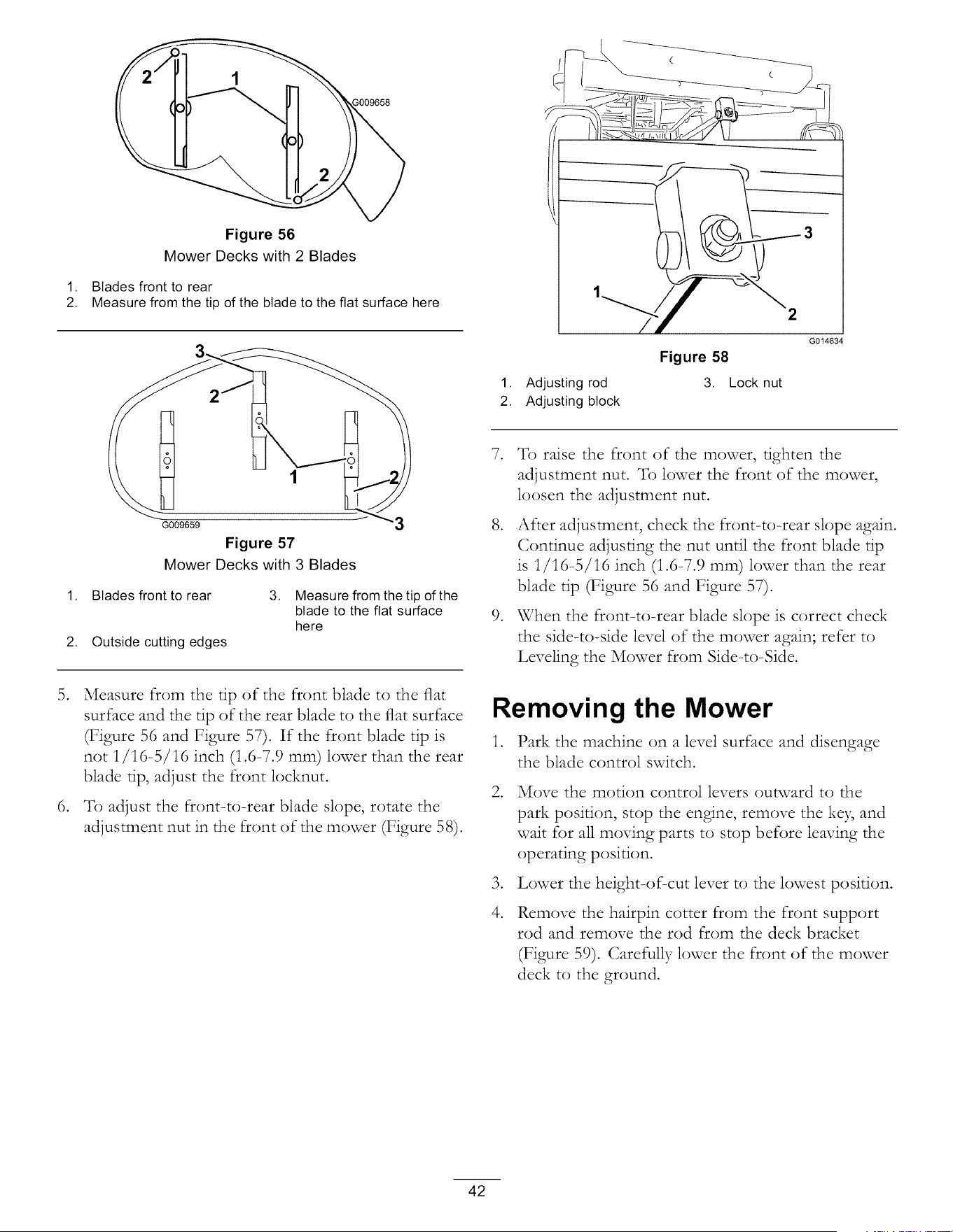
Figure 56
Mower Decks with 2 Blades
1. Blades front to rear
2. Measure from the tip of the blade to the flat surface here
1. Adjusting rod
2. Adjusting block
2
Figure 58
3. Lock nut
G014634
.
.
G009659
Figure 57
Mower Decks with 3 Blades
1. Blades front to rear 3.
2. Outside cutting edges
Measure from the tip of the
blade to the flat surface
here
Measure from the tip of the front blade to the fiat
surface and the tip of the rear blade to the fiat surface
(Figure 56 and Figure 57). If the front blade tip is
not 1/16-5/16 inch (1.6-7.9 ram) lower than the rear
blade rip, adjust the front locknut.
To adjust the front=to=rear blade slope, rotate the
adjustment nut in the front of the mower (Figure 58).
.
.
.
To raise the front of the mower, tighten the
adjustment nut. _fb lower the front of the mower,
loosen the adjustment nut.
After adjustment, check the front-to-rear slope again.
Continue adjusting the nut until the front blade tip
is 1/16-5/16 inch (1.6-7.9 mm) lower than the rear
blade tip (Figure 56 and Figure 57).
When the front=to-rear blade slope is correct check
the side-to-side level of the mower again; refer to
Leveling the Mower from Side-to-Side.
Removing the Mower
1. Park the machine on a level surface and disengage
the blade control switch.
.
.
4.
Move the motion control levers outward to the
park position, stop the engine, remove the ke3, and
wait for all moving parts to stop before leaving the
operating position.
Lower the height-of-cut lever to the lowest position.
Remove the hairpin cotter from the front support
rod and remove the rod from the deck bracket
(Figure 59). Carefully lower the front of the mower
deck to the ground.
42
.
3
1. Front support rod
2. Locking nut
G014635
Figure 59
3. Deck bracket
Lift the mower deck and hanger brackets clear of
the rear lift rod and lower the mower carefully to
the ground (Figure 60).
1. Mower deck
2. Hanger bracket
G005077
Figure 60
3. Rear lift rod
Mower Belt Maintenance
Inspecting the Belts
Service Interval: Every 25 hours--Check the belts for
wear/cracks.
Check the belts for cracks, frayed edges, burn marks, or
any other damage. Replace damaged belts.
Replacing the Mower Belt
Squealing when the belt is rotating, blades slipping when
cutting grass, frayed belt edges, burn marks, and cracks
are signs of a worn mower belt. Replace the mower belt
if aW of these conditions are evident.
1. Park the machine on a level surface and disengage
the blade control switch.
.
.
.
Move the motion control levers outward to the
park position, stop the engine, remove the key and
wait for all moving parts to stop before leaving the
operating position.
Set the height-of-cut at the lowest cutting position
[i-1/2 inch (38 mm)].
Using a spring removal tool, (Toro part no. 92-5771),
remove the idler spring from the deck hook to
remove tension on the idler pulley and roll the belt
oft-of the pulleys (Figure 61 and Figure 62).
The spring is under tension when installed and
can cause personal injury.
Be careful when removing the belt.
6. Slide the mower deck rearward to remove the mower
belt from the engine pulley.
7. Slide the mower deck out from underneath the
machine.
Note: Retain all parts for future installation.
43
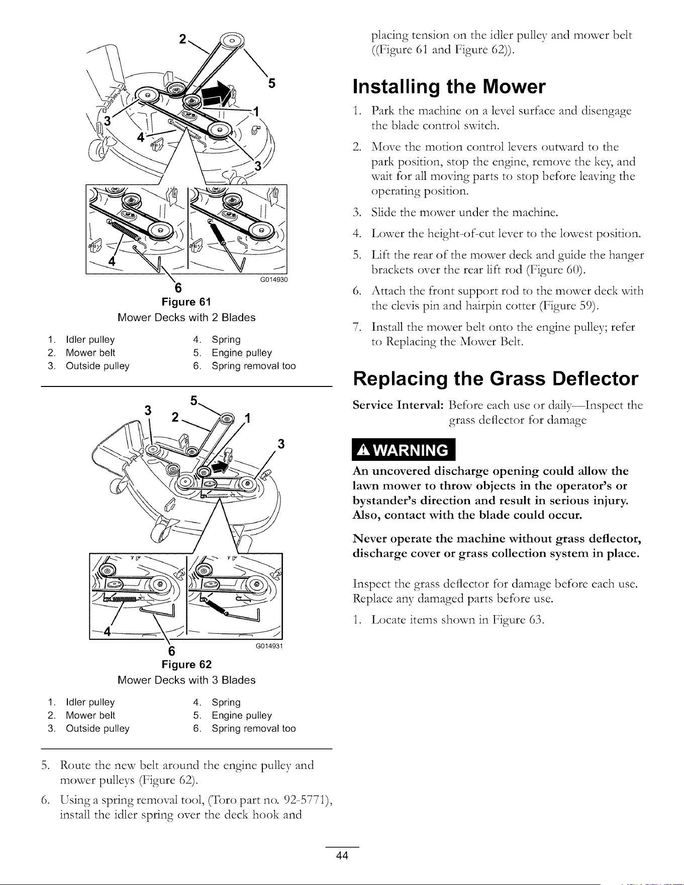
6
Figure 61
Mower Decks with 2 Blades
1. Idler pulley 4. Spring
2. Mower belt 5. Engine pulley
3. Outside pulley 6. Spring removal too
3
3
,_ ,_.-_7_ ,__ ,_
G014931
Figure 62
Mower Decks with 3 Blades
1. Idler pulley 4. Spring
2. Mower belt 5. Engine pulley
3. Outside pulley 6. Spring removal too
placing tension on the idler pulley and mower belt
((Figure 61 and Figure 62)).
Installing the Mower
1. Park the machine on a level surface and disengage
the blade control switch.
. Move the motion control levers outward to the
park position, stop the engine, remove the ke}; and
wait for all moving parts to stop before leaving the
operating position.
3. Slide the mower under the machine.
4. Lower the height-of-cut lever to the lowest position.
5. Lift the rear of the mower deck and guide the hanger
brackets over the rear lift rod (Figure 60).
6. Attach the front support rod to the mower deck with
the clevis pin and hairpin cotter (Figure 59).
7. Install the mower belt onto the engine pulley; refer
to Replacing the Mower Belt.
Replacing the Grass Deflector
Service Interval: Before each use or daily--Inspect the
grass deflector for damage
An uncovered discharge opening could allow the
lawn mower to throw objects in the operator's or
bystander's direction and result in serious injury.
Also, contact with the blade could occur.
Never operate the machine without grass deflector,
discharge cover or grass collection system in place.
Inspect the grass deflector for damage before each use.
Replace aW damaged parts before use.
1. Locate items shown in Figure 63.
5. Route the new belt around the engine pulley and
mower pulleys (Figure 62).
6. Using a spring removal tool, (Toro part no. 92-5771),
install the idler spring over the deck hook and
44
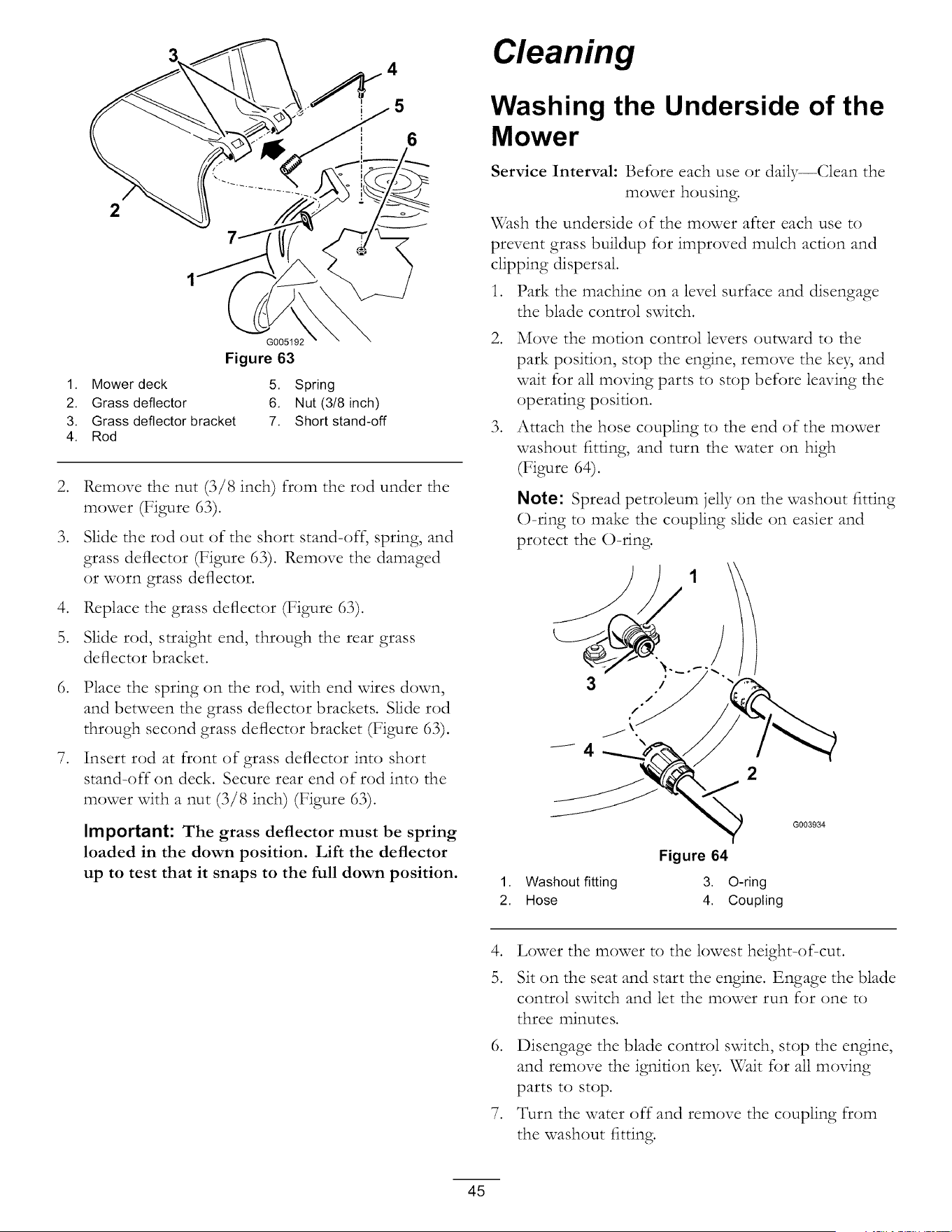
.
.
.
5.
.
.
4
6
2
G005192
Figure 63
1. Mower deck 5. Spring
2. Grass deflector 6. Nut (3/8 inch)
3. Grass deflector bracket 7. Short stand-off
4. Rod
Remove the nut (3/8 inch) from the rod under the
mower (Figure 63).
Slide the rod out of the short stand-off; spring, and
grass deflector (Figure 63). Remove the damaged
or worn grass deflector.
Replace the grass deflector (Figure 63).
Slide rod, straight end, through the rear grass
deflector bracket.
Place the spring on the rod, with end wires down,
and between the grass deflector brackets. Slide rod
through second grass deflector bracket (Figure 63).
Insert rod at front of grass deflector into short
stand-off on deck. Secure rear end of rod into the
mower with a nut (3/8 inch) (Figure 63).
Important: The grass deflector must be spring
loaded in the down position. Lift the deflector
up to test that it snaps to the full down position.
Cleaning
Washing the Underside of the
Mower
Service Interval: Before each use or daily--Clean the
mower housing.
Wash the underside of the mower after each use to
prevent grass buildup for improved mulch action and
clipping dispersal.
1. Park the machine on a level surface and disengage
the blade control switch.
2. Move the motion control levers outward to the
park position, stop the engine, remove the ke B and
wait for all moving parts to stop before leaving the
operating position.
3. Attach the hose coupling to the end of the mower
washout fitting, and turn the water on high
(Figure 64).
Note: Spread petroleum jelly on the washout fitting
()=ring to make the coupling slide on easier and
protect the ()=ring.
3
2
Figure 64
1. Washout fitting 3. O-ring
2. Hose 4. Coupling
G003934
.
5.
Lower the mower to the lowest height=of=cut.
Sit on the seat and start the engine. Engage the blade
control switch and let the mower run for one to
three minutes.
6. Disengage the blade control switch, stop the engine,
and remove the ignition ke> Wait for all moving
parts to stop.
7. Turn the water off-and remove the coupling from
the washout fitting.
45
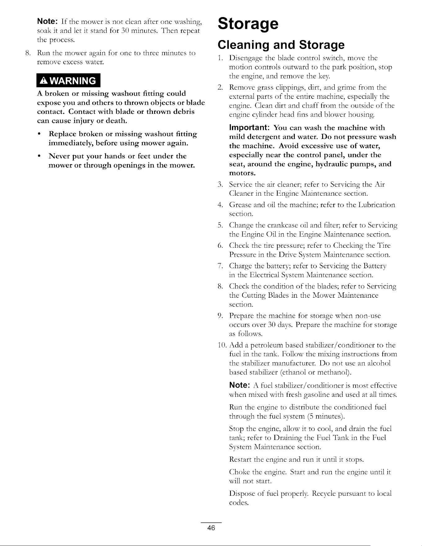
.
Note: If the mower is not clean after one washing,
soak it and let it stand for 30 minutes. Then repeat
the process.
Run the mower again for one to three minutes to
remove excess water.
A broken or missing washout fitting could
expose you and others to thrown objects or blade
contact. Contact with blade or thrown debris
can cause injury or death.
• Replace broken or missing washout fitting
immediately, before using mower again.
• Never put your hands or feet under the
mower or through openings in the mower.
Storage
Cleaning and Storage
1. Disengage the blade control switch, move the
motion controls outward to the park position, stop
the engine, and remove the ke>
2. Remove grass clippings, dirt, and grime from the
external parts of the entire machine, especially the
engine. Clean dirt and chaff from the outside of the
engine cylinder head fins and blower housing.
Important: You can wash the machine with
mild detergent and water. Do not pressure wash
the machine. Avoid excessive use of water,
especially near the control panel, under the
seat, around the engine, hydraulic pumps, and
motors.
3. Service the air cleaner; refer to Servicing the Air
(;leaner in the Engine Maintenance section.
4. Grease and oil the machine; refer to the Lubrication
section.
5. Change the crankcase oil and filter; refer to Servicing
the Engine Oil in the Engine Maintenance section.
6. Check the tire pressure; refer to Checldng the Tire
Pressure in the Drive System Maintenance section.
7. Charge the battery; refer to Servicing the Battery
in the Electrical System Maintenance section.
8. Check the condition of the blades; refer to Servicing
the Cutting Blades in the Mower Maintenance
SeCtiOn.
.
i0.
Prepare the machine for storage when non-use
occurs over 30 days. Prepare the machine for storage
as follows.
Add a petroleum based stabilizer/conditioner to the
fuel in the tank. Follow the mixing instructions from
the stabilizer manufacturer. Do not use an alcohol
based stabilizer (ethanol or methanol).
Note: A fuel stabilizer/conditioner is most effective
when mixed with fresh gasoline and used at all times.
Run the engine to distribute the conditioned fuel
through the fuel system (5 minutes).
Stop the engine, allow it to cool, and drain the fuel
tank; refer to Draining the Fuel Tank in the Fuel
System Maintenance section.
Restart the engine and run it until it stops.
Choke the engine. Start and run the engine until it
will not start.
Dispose of fuel properly. Recycle pursuant to local
codes.
46
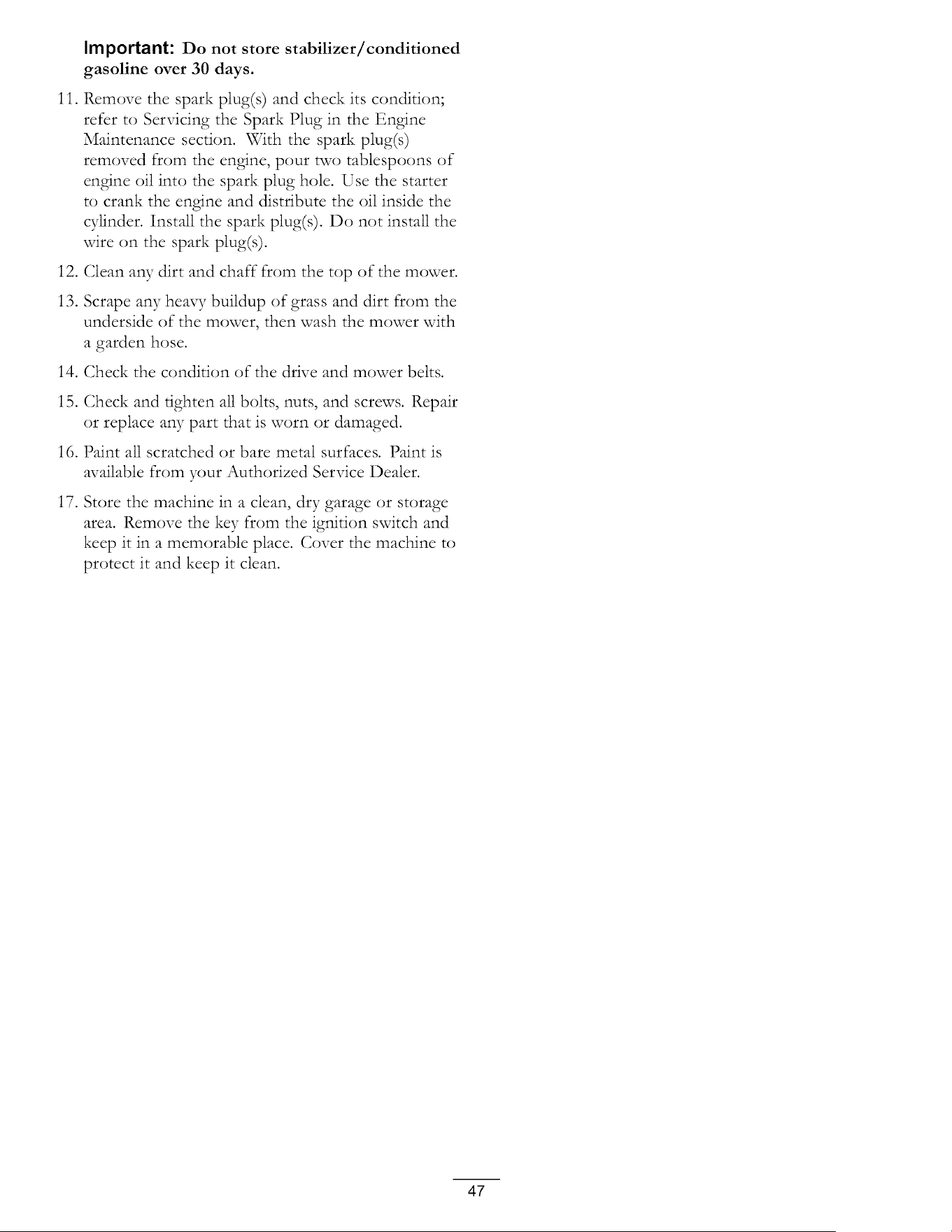
Important: Do not store stabilizer lconditioned
gasoline over 30 days.
11. Remove the spark plug(s) and check its condition;
refer to Servicing the Spark Plug in the Engine
Maintenance section. With the spark plug(s)
removed from the engine, pour two tablespoons of
engine oil into the spark plug hole. Use the starter
to crank the engine and distribute the oil inside the
cylinder. Install the spark plug(s). Do not install the
wire on the spark plug(s).
12. Clean aW dirt and chaff-from the top of the mower.
13. Scrape any heax3 Tbuildup of grass and dirt from the
underside of the mower, then wash the mower with
a garden hose.
14. Check the condition of the drive and mower belts.
15. Check and tighten all bolts, nuts, and screws. Repair
or replace aW part that is worn or damaged.
16. Paint all scratched or bare metal surfaces. Paint is
available from your Authorized Service Dealer.
17. Store the machine in a clean, dry garage or storage
area. Remove the key from the ignition switch and
keep it in a memorable place. Cover the machine to
protect it and keep it clean.
47

Troubleshootin
Problem
The engine overheats.
The starter does not crank 1.
2.
3.
4.
5.
6.
The engine wilt not start, starts hard, or 1.
fails to keep running. 2.
3.
4.
5.
6.
7.
8.
9.
The engine loses power. 1.
2.
3.
4.
The machine does not drive. 1.
2.
Possible Cause Corrective Action
1. The engine load is excessive.
2. The oil level in the crankcase is low.
3. The cooling fins and air passages
under the engine blower housing are
plugged.
4. The air cleaner is dirty.
5.
Dirt, water, or stale fuel is in fuel
system.
The blade control switch is engaged.
The motion control levers are not in the
park position.
The battery is dead.
The electrical connections are corroded
or loose.
A fuse is blown.
A relay or switch is damaged.
The fuel tank is empty.
The choke is not on.
The air cleaner is dirty.
The spark plug wire(s) is loose or
disconnected.
The spark plug(s) is pitted, fouled, or
the gap is incorrect.
There is dirt in fuel filter.
Dirt, water, or stale fuel is in fuel
system.
There is incorrect fuel in the fuel tank.
The oil level in the crankcase is low.
The engine load is excessive.
The air cleaner is dirty.
The oil level in the crankcase is low.
The cooling fins and air passages
under the engine blower housing are
plugged.
5. The spark plug(s) is pitted, fouled, or
the gap is incorrect.
6. The fuel tank vent is blocked.
7. There is dirt in the fuel filter.
8. Dirt, water, or stale fuel is in the fuel
system.
9. There is incorrect fuel in the fuel tank.
3,
4.
The bypass valves are open
The traction belts are worn, loose, or
broken.
The traction belts are off of the pulleys.
The transmission has failed.
1. Reduce ground speed.
2. Add oil to the crankcase.
3. Remove the obstruction from the
cooling fins and air passages.
4. Clean or replace the air cleaner
element.
5. Contact an Authorized Service Dealer
1,
2.
3.
4.
5.
6.
1.
2.
3.
4.
5.
6.
7.
8.
9.
1.
2.
3.
4.
Move the blade control switch to
Disengaged.
Move the motion control levers outward
to the park position.
Charge the battery.
Check the electrical connections for
good contact.
Replace the fuse.
Contact an Authorized Service Dealer.
Fill the fuel tank.
Move the choke lever to On.
Clean or replace the air cleaner
element.
Install the wire(s) on the spark plug.
Install a new, correctly gapped spark
plug(s).
Replace the fuel filter.
Contact an Authorized Service Dealer.
Drain the tank and replace the fuel with
the proper type.
Add oil to the crankcase.
Reduce ground speed.
Clean the air cleaner element.
Add oil to the crankcase.
Remove the obstruction from the
cooling fins and air passages.
5. Install a new, correctly gapped spark
plug(s).
6. Contact an Authorized Service Dealer.
7. Replace the fuel filter.
8. Contact an Authorized Service Dealer.
g,
Drain the tank and replace the fuel with
the proper type.
1. Close the tow valves.
2. Contact an Authorized Service Dealer.
3. Contact an Authorized Service Dealer.
4. Contact an Authorized Service Dealer.
48
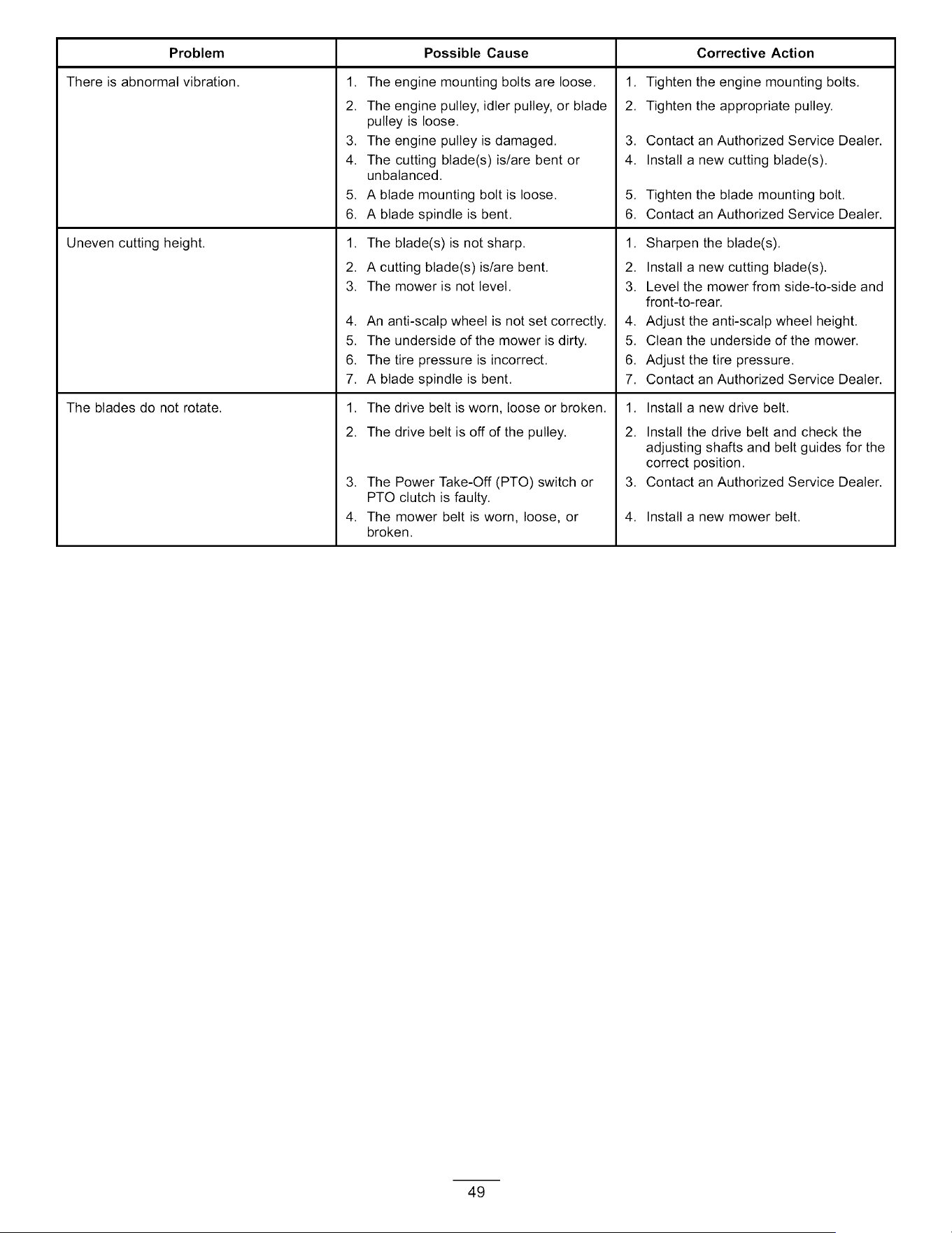
Problem Possible Cause
There is abnormal vibration.
Uneven cutting height.
The blades do not rotate.
1. The engine mounting bolts are loose.
2. The engine pulley, idler pulley, or blade
pulley is loose.
3. The engine pulley is damaged.
4. The cutting blade(s) is/are bent or
unbalanced.
5. A blade mounting bolt is loose.
6. A blade spindle is bent.
1. The blade(s) is not sharp.
2. A cutting blade(s) is/are bent.
3. The mower is not level.
4. An anti-scalp wheel is not set correctly.
5. The underside of the mower is dirty.
6. The tire pressure is incorrect.
7. A blade spindle is bent.
1. The drive belt is worn, loose or broken.
2. The drive belt is off of the pulley.
3. The Power Take-Off (PTO) switch or
PTO clutch is faulty.
4. The mower belt is worn, loose, or
broken.
Corrective Action
1. Tighten the engine mounting bolts.
2. Tighten the appropriate pulley.
3. Contact an Authorized Service Dealer.
4. Install a new cutting blade(s).
5. Tighten the blade mounting bolt.
6. Contact an Authorized Service Dealer.
1. Sharpen the blade(s).
2. Install a new cutting blade(s).
3. Level the mower from side-to-side and
front-to-rear.
4. Adjust the anti-scalp wheel height.
5. Clean the underside of the mower.
6. Adjust the tire pressure.
7. Contact an Authorized Service Dealer.
1. Install a new drive belt.
2. Install the drive belt and check the
adjusting shafts and belt guides for the
correct position.
3. Contact an Authorized Service Dealer.
4. Install a new mower belt.
49
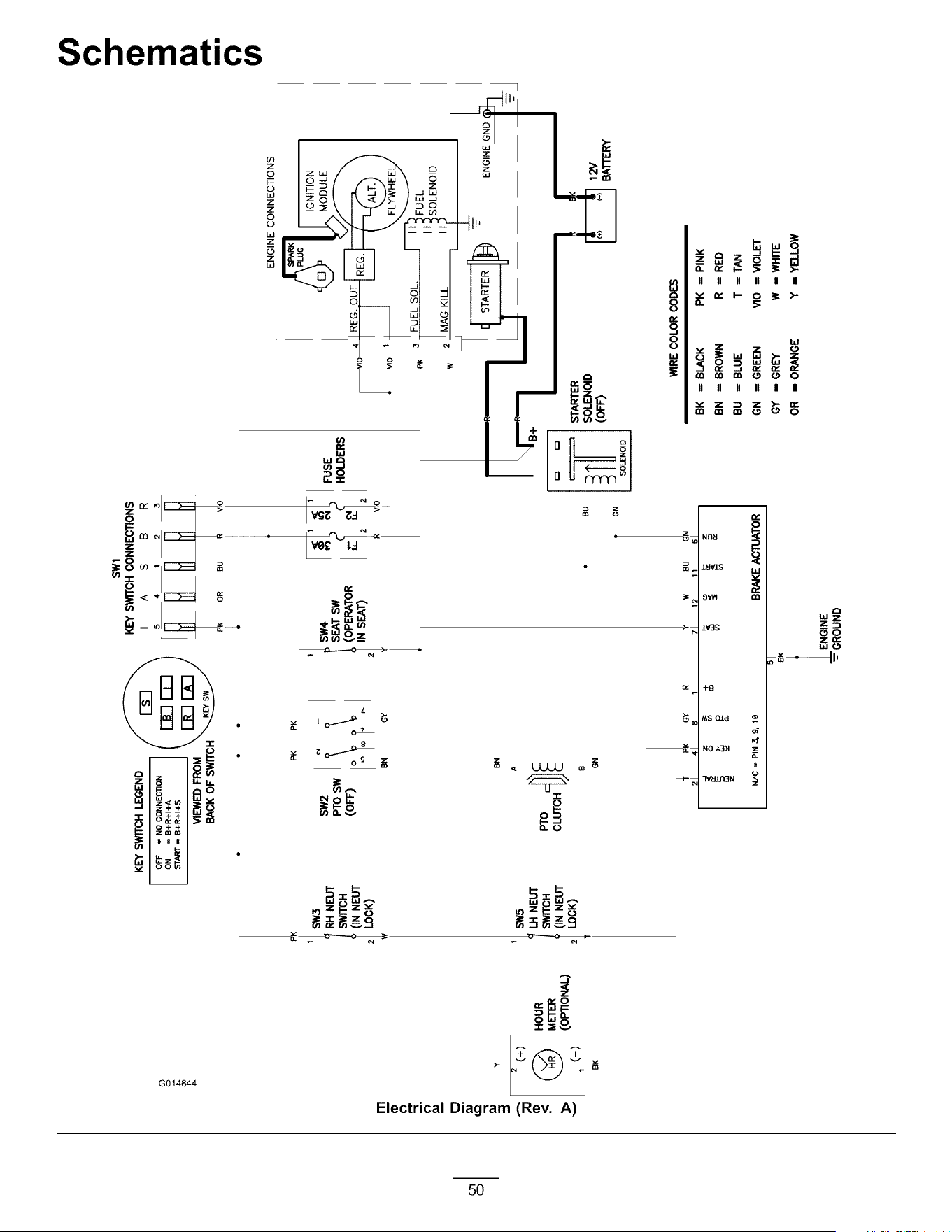
ITI
¢D
€3
--=
€3
0
LQ
B
KEY SWITCH LEGEND _ r--_--I "_
oFF=_O00N_E_O_I f _-----'--r--_\
ON = B+R+I+A I I _ _ I
VI_EDfROM \_o_--/
BACK OF SWITCH
SWl
KEY SWITCH CONNECTIONS
I A S B R
5 4 1 2 3
HOUR
METER
(OPTIONAL)
F
RH NEUT
SWITCH
(IN NEUT
LOCK)
SW5
LH NEUT
SWITCH
(IN NEUT
2 LOCK)
SW2
PTOSW
(OFF)
A
B
(
21 41 81
1t SW4,
SEAT SW
(OPERATOR
IN SEAT)
2
I
+
N/C = PIN _ 9, le
BK
71
in
121
BRAKE ACTUATOR
ENGINE CONNECTIONS
_ _ I IGNITION
FUSE \L J7 I _ MODULE
HOLDERS F. _---IY__y_
'- wo 4 REG. OUT I___ r----F------_ \
, I " ";_OLENO,D
jMAG KILL
r_ I I_i _ STARTER I_ T ENGINEGND
IN ii OlD 12V
NOID I
WIRE COLOR CODES
111 sl BK ==BLACK PK == PINK
BN = BROWN R = RED
BU == BLUE T ==TAN
GN = GREEN VIO = VIOLET
GY = GREY W = WHITE
OR = ORANGE Y = YELLOW
_ENGINE
--- GROUND
0
¢D
3
U_

Notes:
51
The Toro Total Coverage Warranty
Limited Warranty (see warranty periods below)
TimeCutter
and
TITAN
Mowers
Conditions and Products Covered
The Toro Company and its affiliate, Toro Warranty Company, pursuant to
an agreement between them, jointly promise to the original purchaser
to repair the Toro Products listed below if defective in materials or
workmanship.
The following time periods apply from the date of purchase by the original
owner:
Products
All Mowers
•Engine
•Battery
•Belts and Tires
TimeCutter Z Mowers and
Attachments
TITAN Mowers and Attachments
•Frame
TITAN MX Mowers and Attachments
•Frame
Warranty Period
See engine manufacturer's warranty 1
1-90 days Parts and Labor
91-365 days Parts only
90 days
30 Days Commercial Use
3 years Residential Use 2
3 years or 240 hours 3
Lifetime (original owner only) 4
3 years or 400 hours 3
Lifetime (original owner only) 4
1Some engines used on Tore Products are warranted by the engine manufacturer.
2Residential use means use of the product on the same lot as your home, Use at more than one
location is considered commercial use and the commercial use warranty would apply.
3Whichever occurs first,
4Lifetime Frame Warranty _ If the main frame, consisting of the parts welded together to form the
tractor structure that other components such as the engine are secured to, cracks or breaks in
normal use, it will be repaired or replaced, at Toro's option, under warranty at no cost for parts
and labor. Frame failure due to misuse or abuse and failure or repair required due to rust or
corrosion are not covered,
This warranty includes the cost of parts and labor, but you must pay
transportation costs.
2.
3.
Bring the product and your proof of purchase (sales receipt) to the
Service Dealer. The dealer will diagnose the problem and determine
if it is covered under warranty.
If for any reason you are dissatisfied with the Service Dealer's
analysis or with the assistance provided, contact us at:
Customer Care Department, RLC Division
Toro Warranty Company
8111 Lyndale Avenue South
Bloomington, MN 55420-1196
Toll free at 866-216-6029 (U.S. customers)
Toll free at 866-216-6030 (Canadian customers)
Items and Conditions Not Covered
There is no other express warranty except for special emission system
coverage and engine warranty coverage on some products. This express
warranty does not cover the following:
Cost of regular maintenance service or parts, such as filters, fuel,
lubricants, oil changes, spark plugs, air filters, blade sharpening/worn
blade on mowers, cable/linkage adjustments, or brake and clutch
adjustments
• Components failing due to normal wear are not covered by this
warranty
• Any product or part which has been altered or misused and requires
replacement or repair due to accidents or lack of proper maintenance
• Repairs necessary due to improper battery care, failure to use fresh
fuel (less than one month old), or failure to properly prepare the unit
prior to any period of non-use over one month
• Pickup and delivery charges
• Operational misuse, neglect, or accidents
• Repairs or attempted repairs by anyone other than an Authorized
Toro Service Dealer
General Conditions
Warranty may be denied if the hour meter is disconnected, altered, or
shows signs of being tampered with.
Owner Responsibilities
You must maintain your Toro Product by following the maintenance
procedures described in the Operator's Manual. Such routine
maintenance, whether performed by a dealer or by you, is at your expense.
Instructions for Obtaining Warranty Service
If you think that your Toro Product contains a defect in materials or
workmanship, follow this procedure:
1.
Contact any Authorized Toro Service Dealer to arrange service at their
dealership. To locate a dealer convenient to you, refer to the Yellow
Pages of your telephone directory (look under "Lawn Mowers") or
access our web site at www.Toro.com. You may also call the numbers
listed in item #3 to use the 24-hour Toro Dealer Iocator system.
All repairs covered by these warranties must be performed by an
Authorized Toro Service Dealer using Toro approved replacement parts.
Neither The Toro Company nor Toro Warranty Company is liable for
indirect, incidental or consequential damages in connection with the
use of the Toro Products covered by this warranty, including any
cost or expense of providing substitute equipment or service during
reasonable periods of malfunction or non-use pending completion
of repairs under this warranty.
All implied warranties of merchantability (that the product is fit for
ordinary use) and fitness for use (that the product is fit for a particular
purpose) are limited to the duration of the express warranty
Some states do not allow exclusions of incidental or consequential
damages, or limitations on how long an implied warranty lasts, so
the above exclusions and limitations may not apply to you.
This warranty gives you specific legal rights, and you may also have other
rights which vary from state to state.
Countries Other than the United States or Canada
Customers who have purchased Toro products outside the United States or Canada should contact their Toro Distributor (Dealer) to obtain guarantee
policies for your country, province, or state. If for any reason you are dissatisfied with your Distributor's service or have difficulty obtaining guarantee
information, contact the Toro importer. If all other remedies fail, you may contact us at Toro Warranty Company.
374-0258 Rev B
Form No. 3369-576 Rev A
Count on it.
0
0
mmmm
m
Cortac_sped con conductor
TimeCutter_ SS 4235, SS 4260,
SS 5000 y SS 5060
N° de modelo 74624mN ° de serie 311000001 y superiores
N° de modelo 74625mN ° de serie 311000001 y superiores
N° de modelo 74626_N ° de serie 311000001 y superiores
N° de modelo 74630_N ° de serie 311000001 y superiores
N° de modelo 74632_N ° de serie 311000001 y superiores
Para registrar su producto o para descargar un Manual del operador o un Catalogo de piezas sin cargo alguno, vaya Traducci6n del original (ES)
a www.Toro.com.
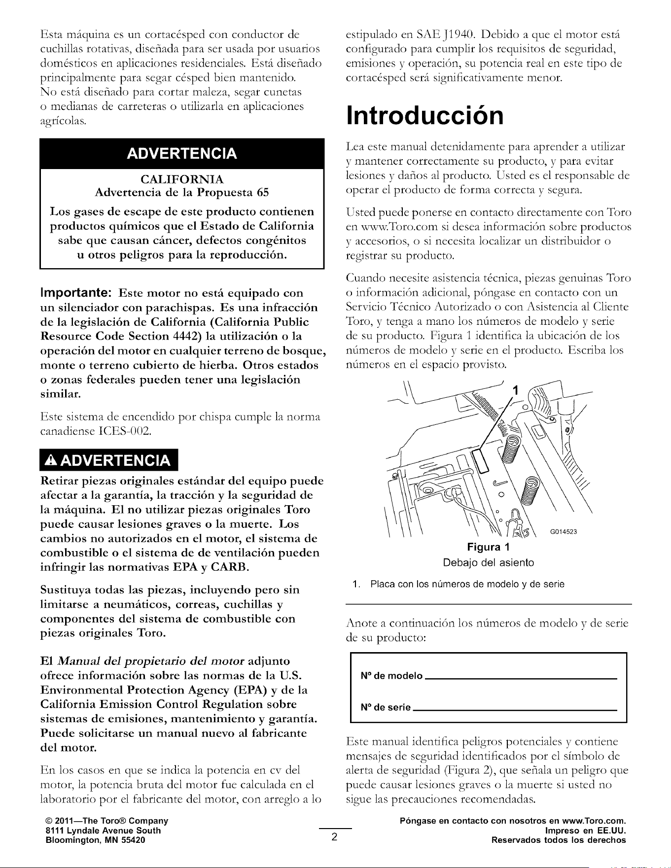
Esta mfiquina es un cortac&ped con conductor de
cuchillas rotativas, disefiada para set usada pot usuarios
dom&dcos en aplicaciones residenciales. Esdt disefiado
principalmente para segar c&ped bien mantenido.
No est(t disefiado para cortar maleza, segar cunetas
o medianas de carreteras o utilizarla en aplicaciones
agdcolas.
CALIFORNIA
Advertencia de la Propuesta 65
Los gases de escape de este producto contienen
productos quimicos que el Estado de California
sabe que causan cfincer, defectos cong_nitos
u otros peligros para la reproducci6n.
Importante: Este motor no estfi equipado con
un silenciador con parachispas. Es una infracci6n
de la legislaci6n de California (California Public
Resource Code Section 4442) la utilizaci6n o la
operaci6n del motor en cualquier terreno de bosque,
monte o terreno cubierto de hierba. Otros estados
o zonas federales pueden tener una legislaci6n
similar.
Este sistema de encendido pot chispa cumple la norma
canadiense ICES-002.
Retirar piezas originales estfindar del equipo puede
afectar a la garantia, la tracci6n y la seguridad de
la mfiquina. E1 no utilizar piezas originales Toro
puede causar lesiones graves o la muerte. Los
cambios no autorizados en el motor, el sistema de
combustible o el sistema de de ventilaci6n pueden
infringir las normativas EPA y CARB.
Sustituya todas las piezas, incluyendo pero sin
limitarse a neumfiticos, correas, cuchillas y
componentes del sistema de combustible con
piezas originales Toro.
E1 Ma_uM del propietario del motor adjunto
ofrece informaci6n sobre las normas de la U.S.
Environmental Protection Agency (EPA) y de la
California Emission Control Regulation sobre
sistemas de emisiones, mantenimiento y garantia.
Puede solicitarse un manual nuevo al fabricante
del motor.
En los casos en que se indica la potencia en cv del
motor, la potencia bruta del motor rue calculada en el
laboratorio pot el fabricante del motor, con arreglo a lo
© 2011--The Toro® Company
8111 Lyndale Avenue South
Bloomington, MN 55420
estipulado en SAE J1940. Debido a que el motor esdt
configurado para cumpfir los requisitos de seguridad,
emisiones y operaci6n, su potencia real en este tipo de
cortac4sped ser(t significativamente menor.
Introduccion
Lea este manual detenidamente para aprender a utilizar
y mantener correctamente su producto, y para evitar
lesiones y dafios al producto. Usted es el responsable de
operar el producto de forma correcta y segura.
Usted puede ponerse en contacto directamente con Toro
en www.Toro.com si desea informaci6n sobre productos
3 accesorios, o si necesita localizar un distribuidor o
registrar su producto.
Cuando necesite asistencia t&nica, piezas genuinas Toro
o informaci6n adicional, p6ngase en contacto con un
Servicio T_cnico Autorizado o con Asistencia al Cliente
Toro, y tenga a mano los nt_meros de modelo y serie
de su producto. Figura i idenrifica la ubicaci6n de los
nt_meros de modelo y serie en el producto. Escriba los
nt_meros en el espacio provisto.
\\
G014523
Figura 1
Debajo del asiento
1. Placa con los nOmeros de modelo y de serie
Anote a condnuaci6n los n_meros de modelo y de serie
de su producto:
N° de modelo
N° de serie
Este manual identifica peligros potenciales y contiene
mensajes de seguridad idendficados pot el dmbolo de
alerta de seguridad (Figura 2), que sefiala un peligro que
puede causar lesiones graves o la muerte si usted no
sigue las precauciones recomendadas.
Pongase en contacto con nosotros en www.Toro.com.
Impreso en EE.UU.
Reservados todos los derechos
1.
Figura 2
Simboto de aterta de seguridad.
Este manual utiliza dos palabras m(ts para resaltar
informaci6n. Importante llama la atenci6n sobre
informaci6n mec(mica especial, y Nota resalta
informaci6n general que merece una atenci6n especial.
Contenido
Introducci_3n ................................................................ 2
Seguridad ..................................................................... 4
Pr_tcticas de operaci6n segura ................................ 4
Seguridad para cortac&pedes Toro con
conductor ......................................................... 6
Indicador de pendientes ........................................ 8
Pegatinas de seguridad e instrucciones ................... 9
E1 producto ................................................................ 15
Controles ........................................................... 16
Operaci6n .................................................................. 17
Primero la seguridad ........................................... 17
Antes del uso ...................................................... 19
C6mo arrancar el motor ...................................... 2i
Operaci6n de las cuchillas ................................... 22
Comprobaci6n del sistema de interruptores
de seguridad ................................................... 22
C6mo parar el motor .......................................... 23
Conducci6n ........................................................ 23
Parada de la m(tquina .......................................... 25
Ajuste de la altura de corte .................................. 25
Colocaci6n del asiento ........................................ 25
Ajuste de las palancas de control de
movimiento .................................................... 26
Empujar la m_tquina a mano ................................ 26
Deflector de hierba ............................................. 27
Consejos de operaci6n ........................................ 27
Mantenimiento ........................................................... 29
Calendario recomendado de mantenimiento ............ 29
Procedimientos previos al mantenimiento ............... 30
C6mo levantar el asiento ..................................... 30
Lubricaci6n ............................................................ 30
Engrasado de los cojinetes .................................. 30
Mantenimiento del motor ....................................... 3i
Mantenimiento del limpiador de aire ................... 3i
Mantenimiento del aceite de motor ..................... 32
Mantenimiento de la bujfa ................................... 34
Limpieza del sistema de refrigeraci6n .................. 35
Mantenimiento del sistema de combustible ............. 36
C_3mo cambiar el filtro de combustible en
lfnea ............................................................... 36
Mantenimiento del filtro de emisiones ................. 36
Mantenimiento del sistema elSctrico ........................ 37
C6mo cargar la baterfa ........................................ 37
Mantenimiento de los fusibles ............................. 38
Mantenimiento del sistema de transmisi6n .............. 39
Comprobaci6n de la presi6n de los
neum_tticos ..................................................... 39
Para quitar el freno el_ctrico ................................ 39
Mantenimiento del cortac&ped .............................. 40
Mantenimiento de las cuchillas de corte ............... 40
NNelaci6n de la carcasa de corte ......................... 42
C6mo retirar el cortac&ped ................................ 45
Mantenimiento de la correa del
cortac&ped .................................................... 46
C6mo instalar el cortac&ped .............................. 47
Cambio del deflector de hierba ............................ 47
Limpieza ................................................................ 48
C6mo lavar los bajos del cortac&ped ................... 48
Almacenamiento ........................................................ 49
Limpieza y almacenamiento ................................ 49
Soluci6n de problemas ............................................... 50
Esquemas ................................................................... 52
Seguridad
Esta mfiquina cumple o supera las especificaciones
de la norma ANSI B71.1-2003 vigentes en el
momento de la fabricaci6n. Sin embargo, el uso
o mantenimiento indebido por parte del usuario
o propietario puede causar lesiones. Para reducir
el riesgo de lesiones, cumpla estas instrucciones
de seguridad y preste siempre atenci6n al simbolo
de alerta de seguridad, que significa CUIDADO,
ADVERTENCIA o PELIGRO - "instrucci6n de
seguridad personal". E1 incumplimiento de estas
instrucciones puede dar lugar a lesiones personales
e incluso la muerte.
Pr&cticas de operacibn segura
Este producto es capaz de amputar manos y pies
y de lanzar objetos al aire. Siga siempre todas las
instrucciones de seguridad con el fin de evitar lesiones
corporales graves e incluso la muerte.
Las siguientes instrucciones provienen de la norma
ANSI B71.1-2003. _l-bdo el contenido de esta norma
ANSI es aplicable a esta mftquina; sin embargo,
debido a la aplicaci6n de la norma a muchos tipos de
productos difcrentes, algunos textos pueden parecer
demasiado generales o llevar a malentendidos. En
estos casos, _l_)ro ha modificado el texto para transmitir
el significado de la norma con un lenguaje mejor
adaptado al producto descrito en este Manual de/operal/or.
Puede encontrar informaci6n de seguridad adicional
a las instrucciones contenidas en la norma ANSI y
reproducida a continuaci6n, en el apartado Seguridad
para cortac&pedes con conductor "l-_)ro, al final de esta
secci6n.
Operacion general
• Lea, comprenda 3 siga todas las instrucciones del
manual del operador y las colocadas en la mftquina
antes de arrancarla.
• No coloque las manos o los pies cerca de las piezas
rotativas o debajo de la mftquina. Mantdngase alejado
del conducto de descarga en todo momento.
• S61o permita que utilicen esta mftquina adultos
responsables y familiarizados con las instrucciones.
• Despeje la zona de objetos tales como pie&as,
juguetes, alambres, etc., que podr_an ser recogidos y
arrojados por la cuchilla.
• Asegt_rese de que no haya otras personas en la zona
antes de segar. Pare la mftquina si alguien entra en
la zona.
Nunca transporte pasajeros.
No corte el c4sped en marcha atffts a menos que sea
absolutamente necesario. Antes de desplazarse hacia
atffts y mientras lo hace, mire siempre hacia abajo y
detffts de usted.
Sepa el sentido de descarga del cortac4sped y no
oriente la descarga hacia nadie. Evite descargar
material contra una pared u otra obstrucci6n. E1
material podr_a rebotar hacia el operador. Pare la(s)
cuchilla(s) al cruzar superficies de grava.
No udlice la mftquina sin tenet colocado y
funcionando un deflector, una tapa de descarga o el
sistema de recogida de hierba completo.
Est_ alerta, vaya mfts despacio y extreme las
precauciones en los giros. Mire detffts y al lado antes
de cambiar de direcci6n.
No deje nunca desatendida la m_tquina si estd
funcionando. Siempre desconecte las cuchillas,
ponga el freno de estacionamiento, pare el motor, y
retire la llave antes de bajarse de la mftquina.
Desconecte las cuchillas cuando la mftquina no est4
segando. Pare el motor, espere hasta que se detengan
completamente todos los componentes y retire la
llave antes de limpiar la mftquina, retirar el recogedor
o desatascar el conducto de descarga.
Utilice la mfiquina solamente con luz natural o con
una buena iluminaci6n artificial.
No opere la mftquina bajo la influencia de drogas o
alcohol.
Vigile el trftfico cuando est4 cerca de una calle o
carretera o cuando cruce una.
Extreme las precauciones al cargar o descargar la
mftquina en/desde un remolque o un cami6n.
Siempre utilice protecci6n ocular mientras usa el
cortac4sped.
Los datos indican que en un gran porcentaje
de lesiones relacionadas con cortac4spedes con
conductor esffm involucrados operadores con edades
de 60 afios o mfrs. Los operadores deben evaluar
su capacidad para manejar el cortac4sped con
conductor con suficiente seguridad para protegerse a
si mismos y a otras personas de lesiones graves.
Siempre siga las recomendaciones respecto a
cualquier uso de contrapesos.
Los rayos pueden causar graves lesiones o incluso
la muerte. Si se yen relftmpagos o rayos o se oyen
truenos en la zona, no utilice la mftquina; busque un
lugar donde resguardarse.
Operacion en pendientes
Las pendientes son una de las principales causas
de accidentes pot pdrdida de control y xqaelcos, que
pueden causar lesiones graves o la muerte. En todas
las pendientes y cuestas se necesita tenet un cuidado
especial. Si usted no puede subir la cuesta en marcha
atrfts, o no se siente cdmodo en ella, no la siegue.
No siegue en pendientes o cuestas de mils de
15 grado s.
Estd alerta a zanjas, hoyos, rocas, ondulaciones y
pendientes que cambian el fingulo de operacidn,
puesto que el terreno irregular podrfa volcar la
mfiquina.
Seleccione una velocidad sobre el terreno baja para
que no tenga que parar mientras est_ en la pendiente.
No siegue en pendientes si la hierba est_i mojada. Las
condiciones deslizantes reducen la traccidn y pueden
hacer que la m_iquina parine y que usted pierda el
control.
Mantenga siempre las ruedas mortices engranadas al
bajar pot una pendiente.
Rcduzca la velocidad y extreme las precauciones en
cuestas o pendientes.
No haga cambios bruscos de velocidad o de
direccidn.
Retire o sefiale cualquier obst_iculo, como pot
ejemplo pie&as, ramas de ftrboles, etc., de la zona de
siega. La hierba alta puede ocultar obstftculos.
Evite arrancar repentinamente al segar cuesta arriba,
porque el cortacdsped podrfa volcar hacia atrfts.
Sepa que podria perder traccidn al bajar cuestas. La
transfcrencia de peso alas ruedas delanteras puede
hacer que patinen las ruedas mortices, causando una
pdrdida de frenado o de direccidn.
Evite siempre arrancar () parar repentinamente
en una cuesta o pendiente. Si las ruedas pierden
traccidn, pare la m_iquina, desengrane las cuchillas y
salga lentamente de la cuesta.
Extreme las precauciones cuando utilice el
recogehierbas u otros accesorios. Estos pueden
cambiar la estabilidad de la m_iquina y causar pdrdidas
de control.
• No intente estabilizar la m_iquina poniendo el pie
en el suelo.
• No siegue cerca de terraplenes, zanjas, taludes
empinados o agua. Si una rueda pasa pot el borde de
un terrapldn o una zanja, puede causar un xqaelco,
que puede dar lugar a lesiones graves o la muerte.
Utilice un cortacdsped dirigido y/o una desbrozadora
manual cerca de terraplenes, zanjas, taludes
empinados o agua.
Ni_os
Pueden ocurrir accidentes tr_gicos si el operador no est_i
alerta a la presencia de nifios. A menudo los nifios se
sienten atra{dos pot la m_iquina y la actividad de segar.
No suponga nunca que los nifios van a permanecer en el
tiltimo lugar en que los rio.
• Mantenga a los nifios alejados de la zona de siega y
bajo la atenta mirada de un adulto responsable que
no sea el operador.
• Estd alerta y pare la m_iquina si entran nifios en la
zona.
• Antes de ir hacia atrfts o cambiar de sentido, y
mientras lo hace, mire hacia atrfts, hacia abajo y hacia
los lados pot si hubiera nifios pequefios.
• No lleve nifios en la m_iquina, incluso si las cuchillas
estfin desconectadas. Pueden caerse y sufrir graves
lesiones, o interfcrir con la operacidn segura de la
m_iquina.
• Cualquier nifio que haya sido transportado en el
pasado puede aparecer de pronto en la zona de
trabajo buscando otto paseo, y puede set arrollado
pot el cortacdsped, incluso en marcha atrfts.
• Nunca permita a los nifios urilizar la m_iquina.
• Extreme la precaucidn al acercarse a esquinas ciegas,
arbustos, ftrboles, el extremo de una valla u otros
objetos que puedan dificultar la visidn.
Remolcado
Estft disponible un kit de enganche para esta m_iquina,
que puede obtenerse a travds de un Distribuidor
autorizado Toro. No remolque sin haber instalado este
enganche homologado. Las siguientes directrices son
aplicables cuando se remolca con el kit de enganche
homologado instalado.
• Rcmolque finicamente si la m_iquina tiene un
enganche disefiado para el remolcado. Enganche
el equipo a remolcar finicamente en el punto de
enganche.
• Siga las recomendaciones del fabricante sobre los
limites de peso de los equipos remolcados y sobre
remolcar en pendientes.
• No deje que suban nifios u otras personas en los
equipos remolcados.
• En las pendientes, el peso del equipo remolcado
pucdc eausar una p&dida de traeei6n y de control.
• Conduzea lcntamcntc y dcjc una distancia de parada
mayor.
Mantenimiento
Manejo seguro de la gasolina:
Para evitar lesiones personales o dafios matcriales,
extreme las precauciones al manejar la gasolina y otros
combustibles. Son inflamables y sus vapores son
explosivos.
• Apague cualquier cigarrillo, cigarro, pipa u otra
fuente de ignici6n.
• Udlice solamente un recipiente homologado.
• No retire nunca el tap6n de combustible ni afiada
combustible con el motor en marcha. Deje que se
enfrfe el motor antes de repostar combustible.
• No reposte nunca la miquina en un recinto cerrado.
• No guarde nunca la maquina o un recipiente de
combustible dentro de un edificio cerca de una llama
desnuda, pot ejemplo, cerca de un calentador de
agua o una caldera.
• No llene nunca los recipientes dentro de un vehfculo
o sobre la carcasa de un cami6n o remolque con
forro de phistico. Coloque siempre los recipientes
de gasolina en el suelo, lejos del veh_culo, antes de
llenarlos.
• Retire un equipo con motor de gasolina del cami6n
o del remolque y rep6stelo en el suelo. Si esto no
es posible, reposte el equipo desde un recipiente
port_til, en vez de usar un surtidor o boquilla
dosificadora de gasolina.
• Mantenga la boquilla en contacto con el horde del
dep6sito de combustible o el orificio del recipiente
en todo momento hasta que termine de repostar. No
urilice dispositivos que mantengan abierta la boquilla.
• Si se derrama combustible sobre su ropa, c_mbiese
de ropa inmediatamente.
• Nunca llene demasiado el dep6sito de combustible.
Vuelva a colocar el tap6n de gasolina y apri&elo
firmemente.
Mantenimiento generah
• No haga funcionar nunca la m_iquina en un lugar
cerrado. Los gases de escape del motor contienen
mon6xido de carbono, que es un veneno inodoro
que puede matarle.
• Mantenga firmemente apretados los pernos y las
tuercas, sobre todo los pernos de acoplamiento de las
cuchillas. Mantenga el equipo en buenas condiciones
de funcionamiento.
No manipule nunca los disposidvos de seguridad.
Compruebe regularmente que funcionan
correctamente.
• Mantenga la m_quina libre de acumulaciones de
hierba, hojas y otros residuos. Limpie cualquier
derrame de aceite o combustible y retire cualquier
residuo empapado en combustible. Deje que se
enfrfe la m_quina antes de almacenarla.
• Pare e inspeccione el equipo si golpea un objeto. Si
es necesario, rep_rela antes de arrancar de nuevo.
• Nunca haga ajustes o reparaciones con el motor en
marcha.
• Los componentes del recogehierbas estin sujetos
a desgaste, dafios y deterioro, y podrfan quedar
expuestas las piezas m6viles y arrojarse objetos
hacia el exterior. Compruebe frecuentemente
los componentes y sustitdyalos con las piezas
recomendadas pot el fabricante cuando sea necesario.
• Las cuchillas del cortac&ped estin afiladas y pueden
cortarle. Emmelva la(s) cuchilla(s) o lleve guantes,
y extreme las precauciones al realizar tareas de
mantenimiento.
Compruebe frecuentemente el correcto
funcionamiento de los frenos. Ajdstelos y realice el
mantenimiento de los mismos cuando sea necesario.
Rcpare o sustituya las pegatinas de seguridad e
instrucciones cuando sea necesario.
Utilice solamente piezas de repuesto genuinas Toro
para asegurar que se mantengan los niveles de calidad
originales.
Seguridad para cortacdspedes
Toro con conductor
La siguiente lista contiene informaci6n especKica para
productos Toro u otra informaci6n sobre seguridad
que usted debe saber y que puede no estar incluida en
la norma ANSI.
• Pare el motor, mueva las palancas de control de
movimiento a punto muerto y luego hacia fuera, a la
posici6n de aparcar, desengrane el mando de control
de las cuchillas, retire la llave y desconecte el/los
cable/s de la/s bujfa/s antes de realizar cualquier
revisi6n, reparaci6n, mantenimiento o ajuste.
• Cuando el motor est_ en marcha, mantenga las
manos, los pies, el pelo y la ropa suelta alejados de
la zona de descarga de los accesorios, los bajos del
cortac&ped y las piezas en movimiento.
No toqueningtSnequipoo piezaquepueda
estarcalientedebidoala operaci6n.Dejequese
enfr{enantesderealizarcualquieroperaci6nde
mantenimiento,ajusteo revisi6n.
E1 ftcido de la bateria es venenoso y puede causar
quemaduras. Evite el contacto con la piel, los ojos y
la ropa. Protdjase la cara, los ojos y la ropa cuando
trabaje con una bater_a.
Los gases de la bater_a pueden explotar. Mantenga
alejados de la bater_a cigarrillos, chispas y llamas.
Utilice solamente accesorios homologados pot
Toro. La garant_a puede quedar anulada si se utilizan
accesorios no autorizados.
Para cargar la m_iquina en un remolque o cami(;n,
utilice finicamente una sola tampa de ancho
completo. E1 fmgulo de la tampa no debe superar
los 15 grados.
Indicador de pendientes
|
Ii\\
| i l\
\
|ll\
|ll \
| II \
| II \
| l l \
I l \ \
I l \ \
! l \ \
I l \ \
\
I l \
I l \ \
\
! l
\
! l
\
I l
\
! l \
I l
\
\
\
\
\
\ \
| 1 l \
I l \ \
I l \ \
I l \ \
I l \ \
Figura 3
Esta pagina puede copiarse para el uso personal.
o
\
G011841
1. La pendiente m_xima en que puede utilizarse la m_quina con seguridad es de 15 grados. Utilice et Diagrama de pendientes para
determinar et _ngulo de una pendiente antes de proseguir. No utilice esta maquina en pendientes de mas de 15 grados.Dobte
por la tinea correspondiente a ta pendiente recomendada.
2. Atinee este borde con una superficie vertical (_rbol, edificio, el poste de una vatla, etc.).
3. Ejemplo de c6mo comparar la pendiente con et borde dobtado.
Pegatinas de seguridad e
instrucciones
Las pegatinas de seguridad e instrucciones estfin a la vista del operador y estfin ubicadas cerca de
cualquier zona de peligro potencial. Sustituya cualquier pegatina que est8 dafiada o que fake.
114-1606
1. Peligro de enredamiento, correa - mantenga cotocados
todos los protectores.
93-7009
1. Advertencia - no haga funcionar et cortac6sped con
el deflector elevado o retirado; mantenga cotocado el
deflector.
2. Petigro de corte/desmembramiento de mano o pie por la
cuchitla det cortac6sped - no se acerque alas piezas en
movimiento. 1,
99-3943
Para modelos con carcasa de 50 pulgadas
Motor
1,
Marca del fabricante
Indica que la cuchilla ha sido identificada como pieza del
fabricante original de la m_quina.
105-7015
106-8717
1. Lea las instrucciones antes de realizar cuatquier operaci6n
de mantenimiento o ajuste.
2. Compruebe la presi6n de los neum_ticos cada 25 horas
de operaci6n.
3. Engrase cada 25 horas de operaci6n.
4. Motor
Para modelos con carcasa de 42 pulgadas
117-2718
Modelo 74625 solamente

110-6691
0
1. Petigro de objetos arrojados - mantenga a otras personas
a una distancia prudencial de la m_quina.
2. Peligro de objetos arrojados, cortac6sped - no haga
funcionar ei cortac6sped sin que est6 cotocado ei deflector,
la tapa de descarga o et sistema de recogida de hierba.
3. Petigro de corte/desmembramiento de mano o pie - no se
acerque alas piezas en movimiento.
o N
119-8814
1. Posici6n de aparcado 4.
2. R_pido 5.
3. Lento
0
0
0
0
Punto muerto
Marcha atr_s
112-9840
Unidades de 50 pulgadas solamente
1. Lea et Manual del 3.
operador.
2. AItura de corte
119-8870
Retire ta Ilave de contacto
y lea tas instrucciones
antes de reatizar
cualquier operaci6n de
mantenimiento o ajuste a
la m_quina.
0
0
0
0
1. Posici6n de aparcado
2. R_pido
3. Lento
N(¢)
119-8815
4.
5.
0
Punto muerto
Marcha atr_s
1,
S61o en determinados modelos
Altura de corte
10
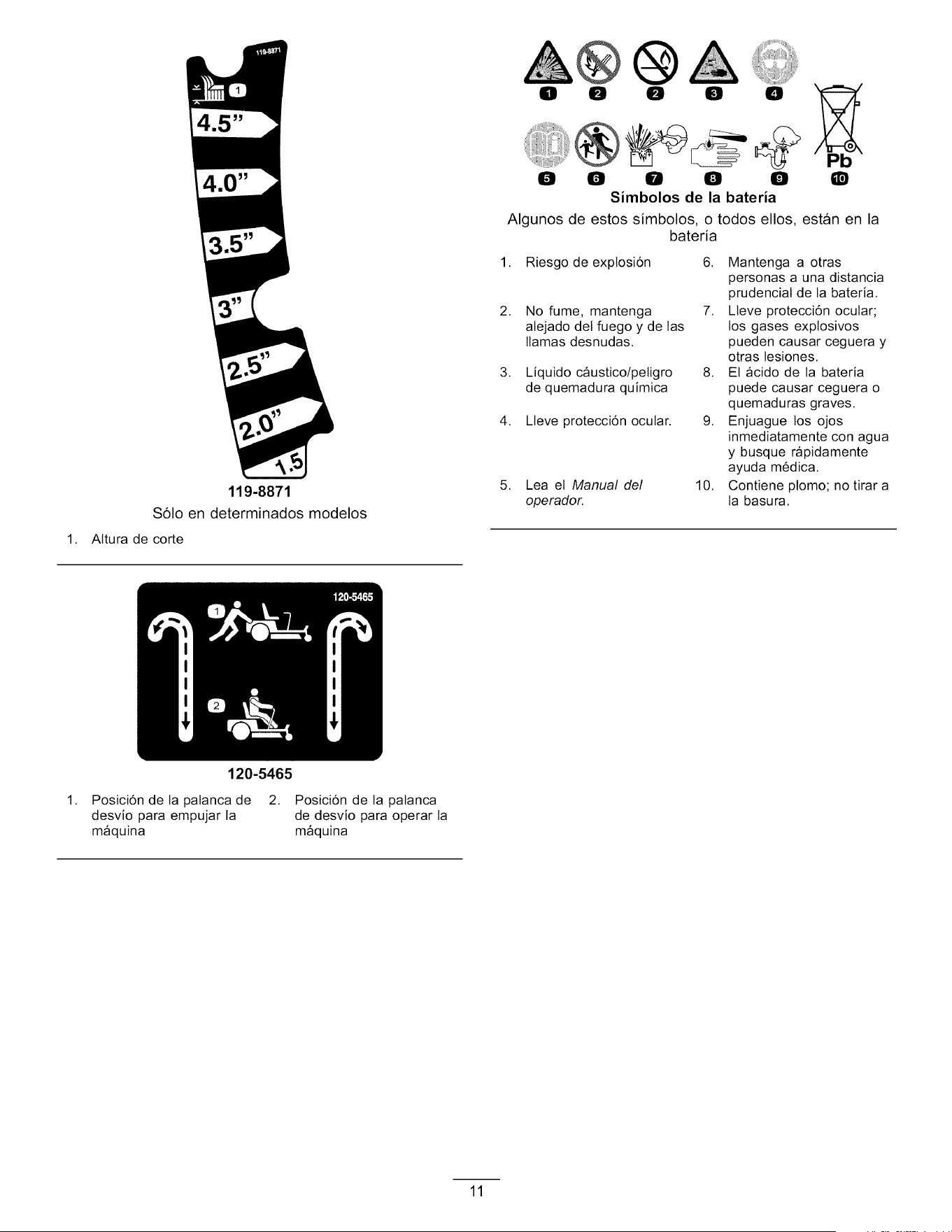
1,
119-8871
S61o en determinados modelos
Altura de corte
120-5465
0 0 0 0 0
0 0 0 0 0
Simbolos de la bateria
Q
Algunos de estos simbolos, o todos ellos, estan en la
bateria
1. Riesgo de explosi6n
2. No fume, mantenga
alejado det fuego y de las
llamas desnudas.
3. Liquido c_ustico/petigro
de quemadura quimica
4. Lleve protecci6n ocular.
5. Lea et Manual del
operador.
6. Mantenga a otras
personas a una distancia
prudencial de la bateria.
7. Lleve protecci6n ocular;
los gases exptosivos
pueden causar ceguera y
otras lesiones.
8. El _cido de la bateria
puede causar ceguera o
quemaduras graves.
9. Enjuague los ojos
inmediatamente con agua
y busque r_pidamente
ayuda m6dica.
10. Contiene plomo; no tirar a
la basura.
1. Posici6n de ta patanca de 2. Posici6n de la patanca
desvio para empujar la de desvio para operar la
m_quina m_quina
11
1. Velocidad baja
119-8874
2. Velocidad atta
1. R_pido
2. Ajuste variable continuo
3. Lento
4. Est_rter
119-8873
S61o en determinados modelos
5. Toma de fuerza (PTO), Mando de control de las cuchillas en
algunos modetos
6. Mando de control de las cuchillas- Desengranado
7. Mando de control de las cuchillas - Engranado
12

1. R_pido
2. Ajuste variable continuo
3. Lento
4. Est_rter
119-8872
S61o en determinados modelos
5. Toma de fuerza (PTO), Mando de control de las cuchillas en
algunos modetos
6. Mando de control de las cuchillas - Engranado
7. Mando de control de las cuchiltas- Desengranado
13
1,
2.
3,
4,
Advertencia - lea el Manual del operador.
120-2239
Advertencia - lea las instrucciones antes de realizar ajustes o
tareas de mantenimiento; mueva las patancas de control de
movimiento a ta posici6n de aparcado (frenado), retire la llave
de contacto y desconecte et cable de la bujia.
Petigro de desmembramiento, cuchilla det cortac6sped;
petigro de enredamiento, correa -- no se acerque a tas piezas
en movimiento; mantenga cotocados todos los protectores.
Petigro de objetos arrojados - mantenga a otras personas a
una distancia prudenciat de la m_quina y recoja cualquier
residuo antes de operar; mantenga cotocado et deflector.
5. Advertencia -- no utitice rampas individuates; utilice una
rampa de ancho compteto al transportar la m_quina.
6. Petigro de p6rdida de tracci6n/control, pendientes - en caso
de p6rdida de tracci6n/control en una pendiente, desengrane
et mando de control de tas cuchillas (toma de fuerza), salga
lentamente de ta pendiente.
7. Petigro de aptastamiento/desmembramiento
de otras personas, marcha atr_s; peligro de
aplastamiento/desmembramiento de otras personas
- no Ileve pasajeros, mire hacia atr_s y hacia abajo mientras
conduzca en marcha atr_s.
8. Petigro de vuetco - no siegue pendientes de m_s de 15
grados, evite giros repentinos y cerrados en las pendientes.
14
El producto
2
\
1. Deflector
2. Rueda motriz trasera
3. Palancas de control de
movimiento
6
12
7
11 2/_._
Figura 4
Modelos con carcasa de 42 pulgadas
4. Patanca de ajuste de altura
de corte
5. Asiento det operador
6. Palanca Smart Speed TM
7. Reposapi6s 10. Motor
8. Tap6n det dep6sito de 11. Protector del motor
combustible (determinados modelos
sotamente)
9. Panel de control 12. Rueda giratoria delantera
2
8
1. Pedal de etevaci6n asistida
(determinados modelos
sotamente)
2. Patanca de ajuste de altura
de corte
3. Palancas de control de
movimiento
4. Asiento det operador
(reposabrazos opcionales)
7
/_ 12
10 1! \
G014910
_14 13
Figura 5
Modelos con carcasa de 50 pulgadas
5. Palanca Smart Speed TM 9. Reposapi6s
13. Deflector
6. Carcasa de corte 10. Tap6n det dep6sito de
combustible
7. Rodillo protectordel c6sped 11. Motor
8. Rueda giratoria delantera 12. Panel de control
14. Rueda motriz trasera
15. Protector det motor
15
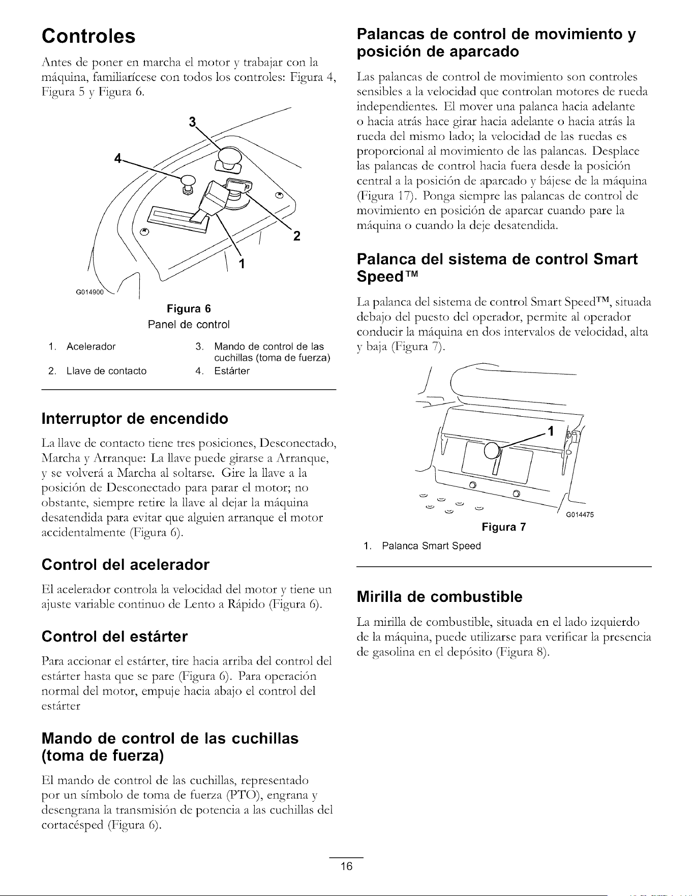
Controles
Antes de poner en marcha el motor y trabajar con la
m(tquina, familiar{cese con todos los controles: Figura 4,
Figura 5 y Figura 6.
2
1
Figura 6
Panel de control
1. Acelerador
2. Llave de contacto
3. Mando de control de tas
cuchiltas (toma de fuerza)
4. Est_rter
Palancas de control de movimiento y
posicion de aparcado
Las palancas de control de movimiento son controles
sensibles a la velocidad que controlan motores de rueda
independientes. E1 mover una palanca hacia adelante
o hacia atr(ts hace girar hacia adelante o hacia atr(ts la
rueda del mismo lado; la velocidad de las ruedas es
proporcional al movimiento de las palancas. Desplace
las palancas de control hacia fuera desde la posici6n
central a la posici6n de aparcado y b(tjese de la m(tquina
(Figura i7). Ponga siempre las palancas de control de
movimiento en posici6n de aparcar cuando pare la
m(tquina o cuando la deje desatendida.
Palanca del sistema de control Smart
Speed TM
La palanca del sistema de control Smart Speed TM, situada
debajo del puesto del operador, permite al operador
conducir la mfiquina en dos intervalos de velocidad, alta
y baja (Figura 7).
Interruptor de encendido
La llave de contacto tiene tres posiciones, Desconectado,
Marcha y Arranque: La llave puede girarse a Arranque,
y se volverfi a Marcha al soltarse. Gire la llave a la
posici6n de Desconectado para parar el motor; no
obstante, siempre retire la llave al dejar la m_quina
desatendida para evitar que alguien arranque el motor
accidentalmente (Figura 6).
Control del acelerador
E1 acelerador controla la velocidad del motor y tiene un
ajuste variable conrinuo de Lento a R(tpido (Figura 6).
Control del estarter
Para accionar el est(trter, tire hacia arriba del control del
est_trter basra que se pare (Figura 6). Para operaci6n
normal del motor, empuje hacia abajo el control del
est(trter
Figura 7
1. Palanca Smart Speed
G014475
Mirilla de combustible
La mirilla de combustible, situada en el 1ado izquierdo
de la m(tquina, puede utilizarse para verificar la presencia
de gasolina en el dep6sito (Figura 8).
Mando de control de las cuchillas
(toma de fuerza)
E1 mando de control de las cuchillas, representado
pot un simbolo de toma de fuerza _T()), engrana y
desengrana la transmisi6n de potencia alas cuchillas del
cortac&ped (Figura 6).
16
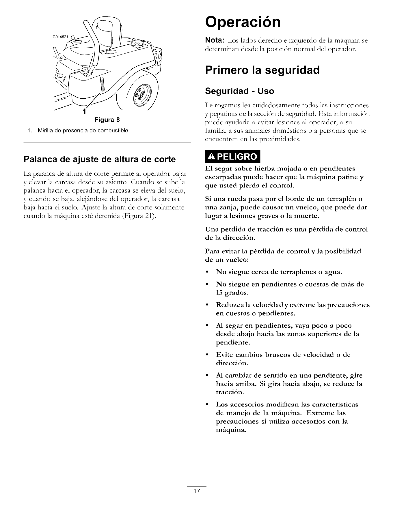
G014521
Ope ""
raclon
Nota: Los lados derecho e izquierdo de la mfiquina se
determinan desde la posici6n normal del operador.
1,
1
Figura 8
Mirilta de presencia de combustible
Primero la seguridad
Seguridad - Uso
Le rogamos lea cuidadosamente todas las instrucciones
y pegarinas de la secci6n de seguridad. Esta informaci6n
puede ayudarle a evitar lesiones al operador, a su
familia, a sus animales dom&ricos o a personas que se
encuentren en las proximidades.
Palanca de ajuste de altura de corte
La palanca de altura de corte permite al operador bajar
y elevar la carcasa desde su asiento. Cuando se sube la
palanca hacia el operador, la carcasa se eleva del suelo,
y cuando se baja, alefimdose del operador, la carcasa
baja hacia el suelo. Ajuste la altura de corte solamente
cuando la m_quina est8 detenida (Figura 2i).
E1 segar sobre hierba mojada o en pendientes
escarpadas puede hacer que la mfiquina patine y
que usted pierda el control.
Si una rueda pasa por el borde de un terrapl_n o
una zanja, puede causar un vuelco, que puede dar
lugar a lesiones graves o la muerte.
Una p&rdida de tracci6n es una p&rdida de control
de la direcci6n.
Para evitar la p&rdida de control y la posibilidad
de un vuelco:
No siegue cerca de terraplenes o agua.
No siegue en pendientes o cuestas de mils de
15 grados.
Reduzca la velocidad y extreme las precauciones
en cuestas o pendientes.
AI segar en pendientes, vaya poco a poco
desde abajo hacia las zonas superiores de la
pendiente.
Evite cambios bruscos de velocidad o de
direcci6n.
• AI cambiar de sentido en una pendiente, gire
hacia arriba. Si gira hacia abajo, se reduce la
tracci6n.
Los accesorios modifican las caracteristicas
de manejo de la mfiquina. Extreme las
precauciones si utiliza accesorios con la
mfiquina.
17
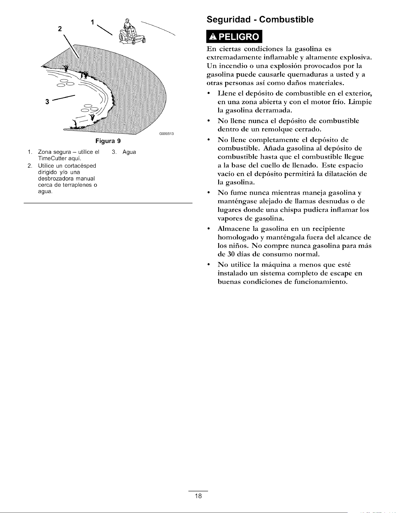
1,
2.
2
Figura 9
Zona segura - utilice el
TimeCutter aqui.
Utitice un cortac6sped
dirigido y/o una
desbrozadora manual
cerca de terraplenes o
agua.
3,
Agua
G000513
Seguridad - Combustible
En ciertas condiciones la gasolina es
extremadamente inflamable y altamente explosiva.
Un incendio o una explosi6n provocados por la
gasolina puede causarle quemaduras a usted y a
otras personas asi como dafios materiales.
• Llene el dep6sito de combustible en el exterior,
en una zona abierta y con el motor frio. Limpie
la gasolina derramada.
• No llene nunca el dep6sito de combustible
dentro de un remolque cerrado.
• No llene completamente el dep6sito de
combustible. Afiada gasolina al dep6sito de
combustible hasta que el combustible llegue
a la base del cuello de llenado. Este espacio
vacio en el dep6sito permitirfi la dilataci6n de
la gasolina.
• No fume nunca mientras maneja gasolina y
mant_ngase alejado de llamas desnudas o de
lugares donde una chispa pudiera inflamar los
vapores de gasolina.
• Mmacene la gasolina en un recipiente
homologado y mant_ngala fuera del alcance de
los nifios. No compre nunca gasolina para mils
de 30 dias de consumo normal.
• No utilice la mfiquina a menos que est_
instalado un sistema completo de escape en
buenas condiciones de funcionamiento.
18
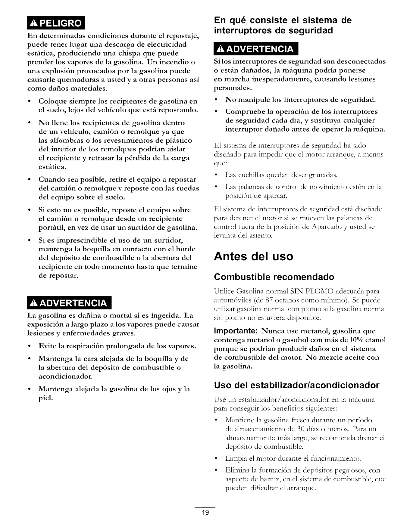
En determinadas condiciones durante el repostaje,
puede tener lugar una descarga de electricidad
estfitica, produciendo una chispa que puede
prender los vapores de la gasolina. Un incendio o
una explosi6n provocados por la gasolina puede
causarle quemaduras a usted y a otras personas asi
como dafios materiales.
Coloque siempre los recipientes de gasolina en
el suelo, lejos del vehiculo que estfi repostando.
No llene los recipientes de gasolina dentro
de un vehiculo, cami6n o remolque ya que
las alfombras o los revestimientos de plfistico
del interior de los remolques podrian aislar
el recipiente y retrasar la p_rdida de la carga
estfitica.
Cuando sea posible, retire el equipo a repostar
del cami6n o remolque y reposte con las ruedas
del equipo sobre el suelo.
Si esto no es posible, reposte el equipo sobre
el cami6n o remolque desde un recipiente
portfitil, en vez de usar un surtidor de gasolina.
Si es imprescindible el uso de un surtidor,
mantenga la boquilla en contacto con el horde
del dep6sito de combustible o la abertura del
recipiente en todo momento hasta que termine
de repostar.
La gasolina es dafiina o mortal si es ingerida. La
exposici6n a largo plazo a los vapores puede causar
lesiones y enfermedades graves.
• Evite la respiraci6n prolongada de los vapores.
• Mantenga la cara alejada de la boquilla y de
la abertura del dep6sito de combustible o
acondicionador.
• Mantenga alejada la gasolina de los ojos y la
piel.
En que consiste el sistema de
interruptores de seguridad
Si los interruptores de seguridad son desconectados
o estfin dafiados, la mfiquina podria ponerse
en marcha inesperadamente, causando lesiones
personales.
• No manipule los interruptores de seguridad.
• Compruebe la operaci6n de los interruptores
de seguridad cada dia, y sustituya cualquier
interruptor dafiado antes de operar la mfiquina.
E1 sistema de interruptores de seguridad ha sido
disefiado para impedir que el motor arranque, a menos
que"
• Las cuchillas quedan desengranadas.
• Las palancas de control de movimiento estSn en la
posici6n de aparcar.
E1 sistema de interruptores de seguridad ester disefiado
para detener el motor si se mueven las palancas de
control fuera de la posici6n de Aparcado y usted se
levanta del asiento.
Antes del uso
Combustible recomendado
Utilice Gasolina normal SIN PLOMO adecuada para
autom6viles (de 87 octanos como m_nimo). Se puede
utilizar gasolina normal con plomo si la gasolina normal
sin plomo no estuviera disponible.
Importante: Nunca use metanol, gasolina que
contenga metanol o gasohol con mils de 10% etanol
porque se podrian producir dafios en el sistema
de combustible del motor. No mezcle aceite con
la gasolina.
Uso del estabilizador/acondicionador
Use un estabilizador/acondicionador en la m(tquina
para conseguir los beneficios siguientes:
• Mantiene la gasolina fresca durante un per_odo
de almacenamiento de 30 dias o menos. Para un
almacenamiento m(ts largo, se recomienda drenar el
dep6sito de combustible.
• Limpia el motor durante el funcionamiento.
• Elimina la formaci6n de dep6sitos pegajosos, con
aspecto de barniz, en el sistema de combustible, que
pueden dificultar el arranque.
19
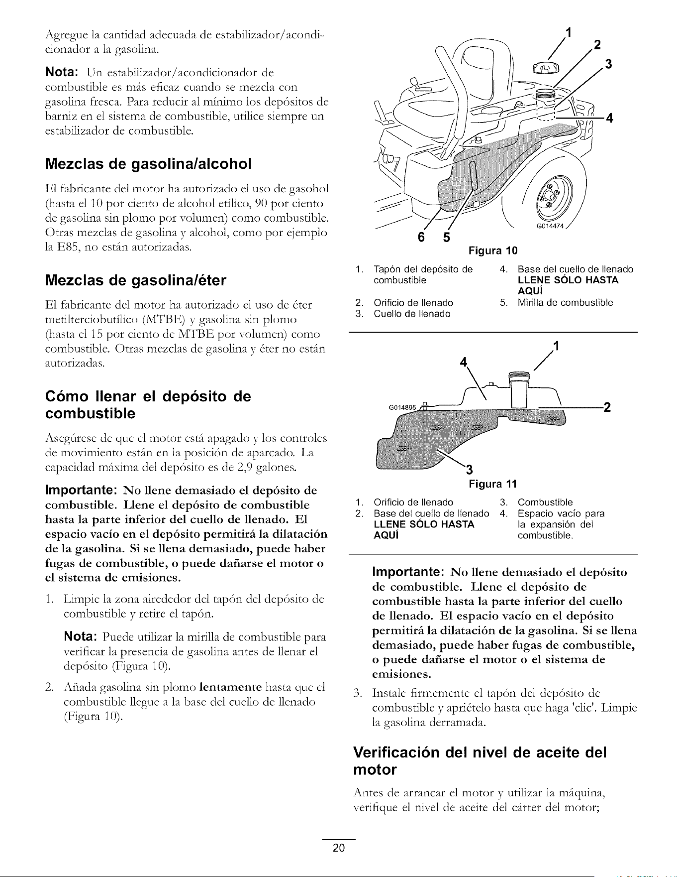
Agregue la cantidad adecuada de estabilizador/acondi-
cionador a la gasolina.
Nota: Un estabilizador/acondicionador de
combustible es mils eficaz cuando se mezcla con
gasolina fresca. Para reducir al minim(:) los dep6sitos de
barniz en el sistema de combustible, utilice siempre un
estabilizador de combustible.
Mezclas de gasolina/alcohol
E1 fabricante del motor ha autorizado el us() de gasohol
(basra el i0 pot ciento de alcohol etiiico, 90 pot ciento
de gasolina sin plomo pot volumen) como combustible.
Otras mezclas de gasolina y alcohol, como pot ejemplo
la E85, no esdm autorizadas.
Mezclas de gasolina/6ter
E1 fabricante del motor ha autorizado el us() de &er
metilterciobutflico (MTBE) y gasolina sin plomo
(basra el i5 pot ciento de MTBE pot volumen) como
combustible. Otras mezclas de gasolina y &er no estfin
autorizadas.
6
5
Figura 10
1. Tap6n det dep6sito de
combustible
1
2
0 3
4
G014474
2. Orificio de Ilenado
3. Cuetto de Ilenado
4. Base det cuetto de Ilenado
LLENE SOLO HASTA
AQUi
5. Mirilta de combustible
Como Ilenar el deposito de
combustible
Asegflrese de que el motor est(t apagado y los controles
de movimiento est(m en la posici6n de aparcado. La
capacidad m(txima del dep6sito es de 2,9 galones.
Importante: No llene demasiado el dep6sito de
combustible. Llene el dep6sito de combustible
hasta la parte inferior del cuello de llenado. E1
espacio vacio en el dep6sito permitirfi la dilataci6n
de la gasolina. Si se llena demasiado, puede haber
fugas de combustible, o puede dafiarse el motor o
el sistema de emisiones.
,
,
Limpie la zona alrededor del tap6n del dep6sito de
combustible y retire el tap6n.
Nota: Puede utilizar la mirilla de combustible para
verificar la presencia de gasolina antes de llenar el
dep6sito (Figura i0).
Afiada gasolina sin plomo lentamente hasta que el
combustible llegue a la base del cuello de llenado
(Figura 10).
G014895 2
1,
2.
3
Figura 11
Orificio de llenado 3. Combustible
Base del cuetto de Ilenado 4. Espacio vacio para
LLENE SOLO HASTA la expansi6n del
AQUi combustible.
°
Importante: No llene demasiado el dep6sito
de combustible. Llene el dep6sito de
combustible hasta la parte inferior del cuello
de llenado. E1 espacio vacio en el dep6sito
permitirfi la dilataci6n de la gasolina. Si se llena
demasiado, puede haber fugas de combustible,
o puede dafiarse el motor o el sistema de
emisiones.
Instale firmemente el tap6n del dep6sito de
combustible y apri&elo basra que haga 'clic'. Limpie
la gasolina derramada.
Verificacion del nivel de aceite del
motor
Antes de arrancar el motor y utilizar la m(tquina,
verifique el nivel de aceite del c(trter del motor;
2O
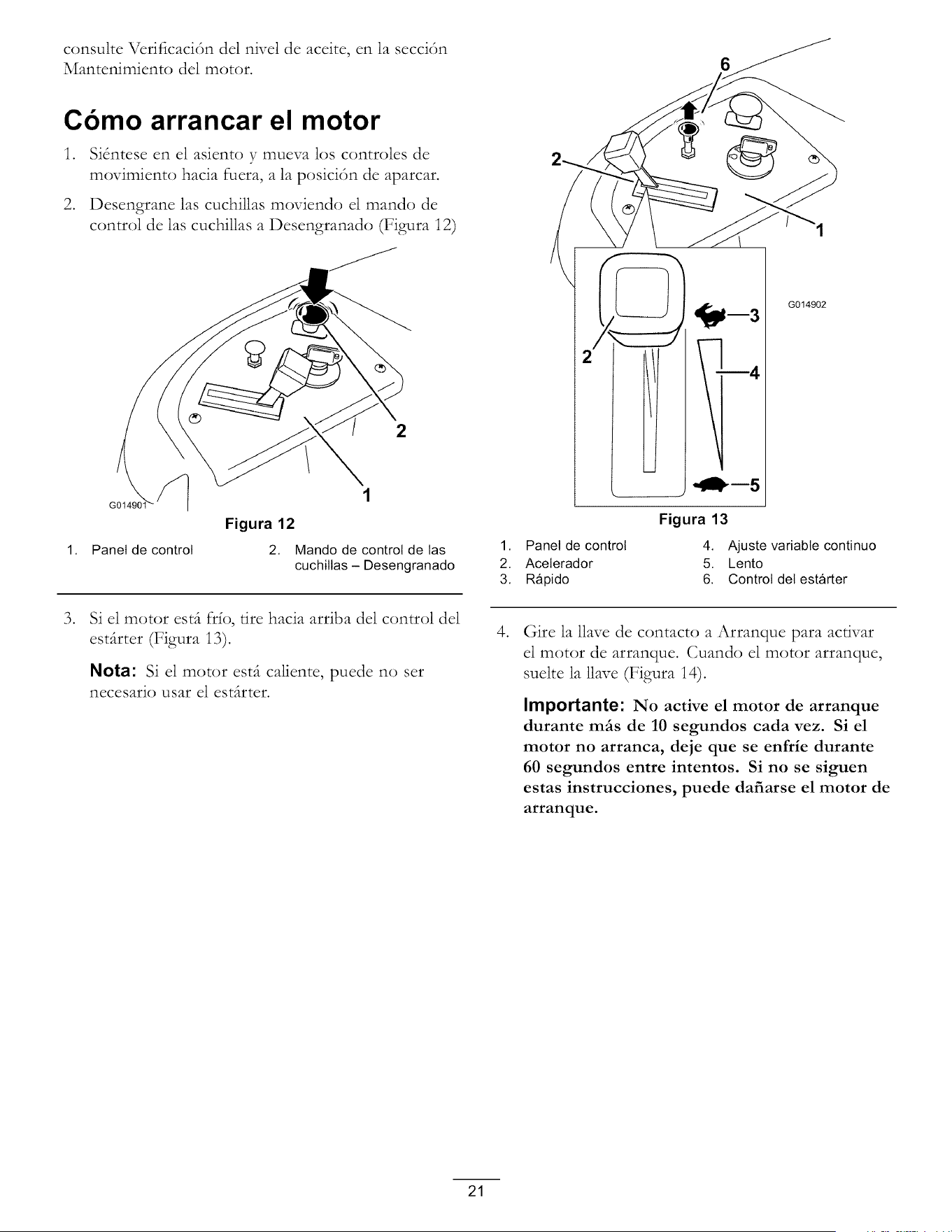
consulte Vcrificaci6n del nivel de aceite, en la secci6n
Mantenimiento del motor.
Cbmo arrancar el motor
.
.
Si_ntese en el asiento y mueva los controles de
movimiento hacia fuera, a la posici6n de aparcar.
Desengrane las cuchillas moviendo el mando de
control de las cuchillas a Desengranado (Figura 12)
2
1. Panel de control
1
Figura 12
2. Mando de control de las
cuchillas - Desengranado
°
Si el motor est(t fr_o, tire hacia arriba del control del
est_irter (Figura i3).
Nota: Si el motor est(t caliente, puede no set
necesario usar el est(trter.
6
J
Figura 13
G014902
1. Panel de control 4. Ajuste variable continuo
2. Aceterador 5. Lento
3. R_pido 6. Control del est_rter
°
Gire la llave de contacto a Arranque para activar
el motor de arranque. Cuando el motor arranque,
suelte la llave (Figura 14).
Importante: No active el motor de arranque
durante mils de 10 segundos cada vez. Si el
motor no arranca, deje que se enfrie durante
60 segundos entre intentos. Si no se siguen
estas instrucciones, puede dafiarse el motor de
arranque.
21
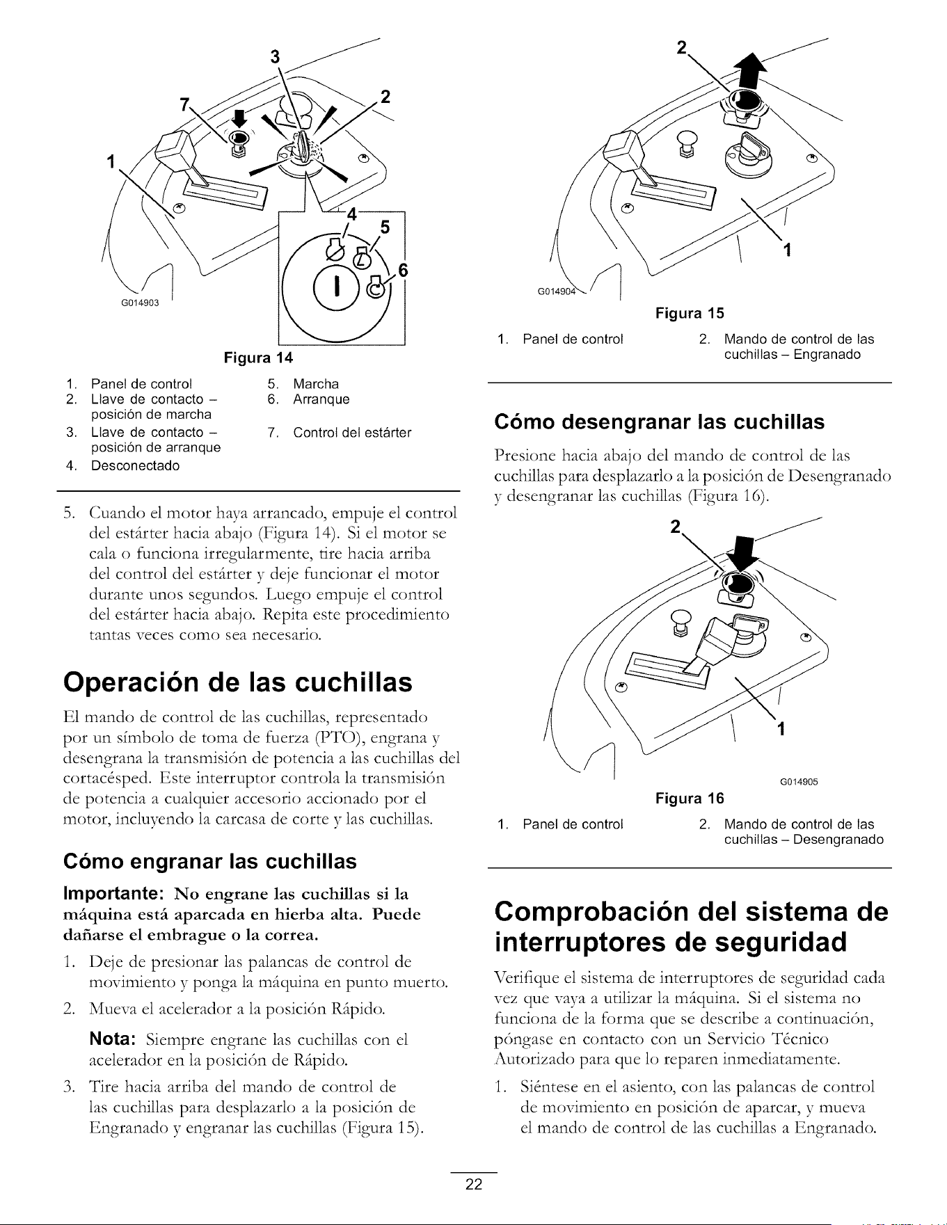
G014903
3
2
1. Panel de control
2. Llave de contacto -
posici6n de marcha
3. Llave de contacto -
posici6n de arranque
4. Desconectado
Figura 14
°
5. Marcha
6. Arranque
7. Control del est_rter
Cuando el motor haya arrancado, empuje el control
del esdtrter hacia abajo (Figura i4). Si el motor se
cala o funciona irregularmente, tire hacia arriba
del control del esdtrter y deje funcionar el motor
durante unos segundos. Luego empuje el control
del esdtrter hacia abajo. Rcpita este procedimiento
tantas veces como sea necesario.
2
\
1. Panel de control
Figura 15
2. Mando de control de las
cuchiltas - Engranado
Como desengranar las cuchillas
Presione hacia abajo del mando de control de las
cuchillas para desplazarlo a la posici6n de Desengranado
y desengranar las cuchillas (Figura 16).
2
\
Operacibn de las cuchillas
E1 mando de control de las cuchillas, representado
pot un sfmbolo de toma de fuerza (PTO), engrana y
desengrana la transmisidn de potencia alas cuchillas del
cortacdsped. Este interruptor controla la transmisidn
de potencia a cualquier accesorio accionado pot el
motor, incluyendo la carcasa de corte y las cuchillas.
Como engranar las cuchillas
Importante: No engrane las cuchillas si la
mfiquina estfi aparcada en hierba alta. Puede
dafiarse el embrague o la correa.
1. Deje de presionar las palancas de control de
movimiento y ponga la m(tquina en punto muerto.
2. Mueva el acelerador a la posicidn Rftpido.
,
Nota: Siempre engrane las cuchillas con el
acelerador en la posici6n de Rftpido.
Tire hacia arriba del mando de control de
las cuchillas para desplazarlo a la posicidn de
Engranado y engranar las cuchillas (Figura 15).
1. Panel de control
G014905
Figura 16
2. Mando de control de las
cuchiltas - Desengranado
Comprobacibn del sistema de
interruptores de seguridad
Vcrifique el sistema de interruptores de seguridad cada
vez que vaya a utilizar la m(tquina. Si el sistema no
funciona de la forma que se describe a continuacidn,
pdngase en contacto con un Servicio Tdcnico
Autorizado para que lo reparen inmediatamente.
1. Sidntese en el asiento, con las palancas de control
de movimiento en posicidn de aparcar, y mueva
el mando de control de las cuchillas a Engranado.
22
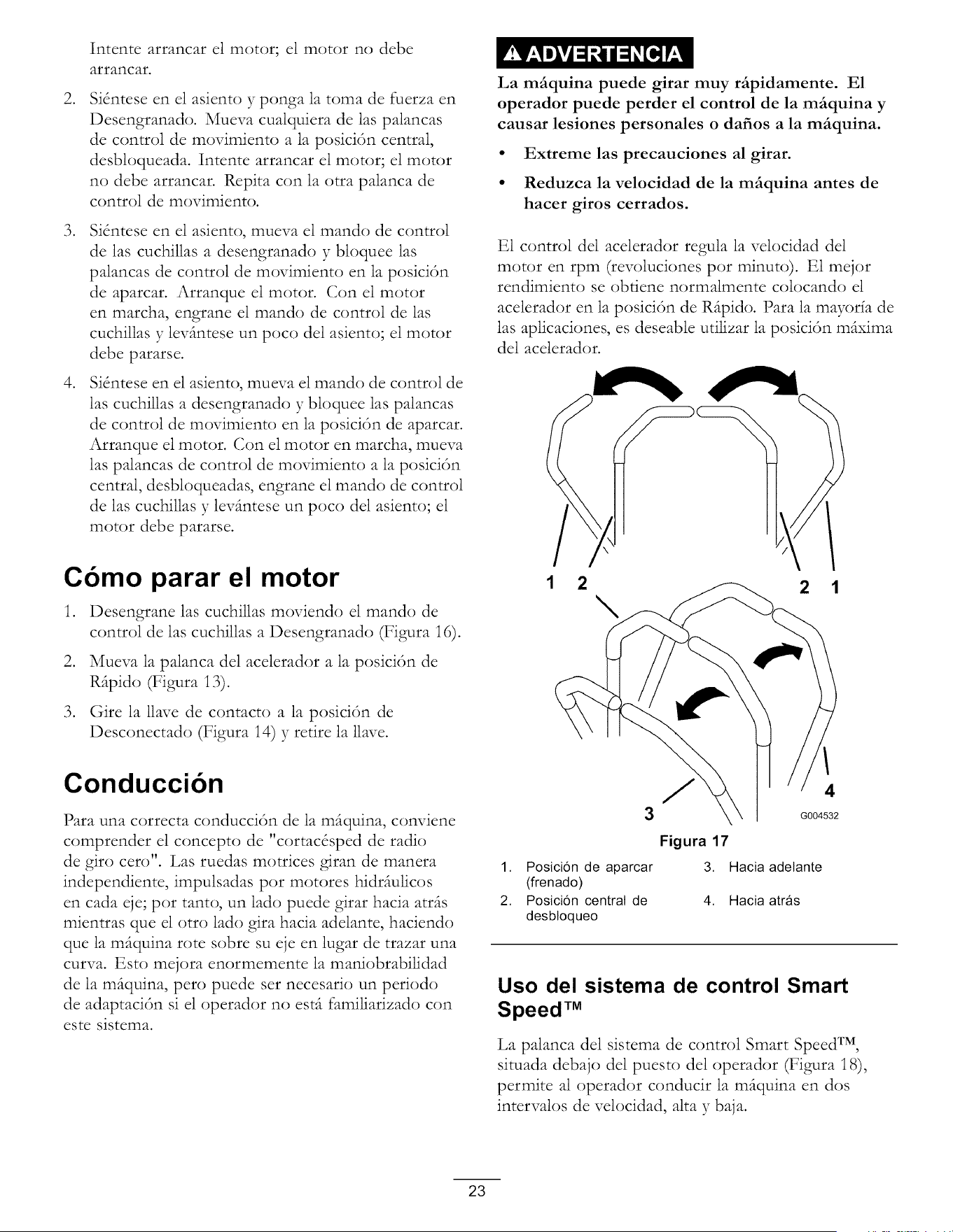
.
.
.
Intentearrancarelmotor;elmotor no debe
arrancar.
SKntese en el asiento y ponga la toma de fuerza en
Desengranado. Mueva cualquiera de las palancas
de control de movimiento a la posici6n central,
desbloqueada. Intente arrancar el motor; el motor
no debe arrancar. Repita con la otra palanca de
control de movimiento.
SKntese en el asiento, mueva el mando de control
de las cuchillas a desengranado y bloquee las
palancas de control de movimiento en la posici6n
de aparcar. Arranque el motor. Con el motor
en marcha, engrane el mando de control de las
cuchillas y lev(mtese un poco del asiento; el motor
debe pararse.
SKntese en el asiento, mueva el mando de control de
las cuchillas a desengranado y bloquee las palancas
de control de movimiento en la posici6n de aparcar.
Arranque el motor. Con el motor en marcha, mueva
las palancas de control de movimiento a la posici6n
central, desbloqueadas, engrane el mando de control
de las cuchillas y lev(mtese un poco del asiento; el
motor debe pararse.
La mfiquina puede girar muy rfipidamente. E1
operador puede perder el control de la mfiquina y
causar lesiones personales o dafios a la mfiquina.
• Extreme las precauciones al girar.
• Reduzca la velocidad de la mfiquina antes de
hacer giros cerrados.
E1 control del acelerador regula la velocidad del
motor en rpm (revoluciones pot minuto). E1 mejor
rendimiento se obtiene normalmente colocando el
acelerador en la posici6n de R(tpido. Para la mayor_a de
las aplicaciones, es deseable utilizar la posici6n m(txima
del acelerador.
Cbmo parar el motor
1. Desengrane las cuchillas moviendo el mando de
control de las cuchillas a Desengranado (Figura 16).
2. Mueva la palanca del acelerador a la posici6n de
R_tpido (Figura 13).
3. Gire la llave de contacto a la posici6n de
Desconectado (Figura 14) y retire la llave.
Conduccibn
Para una correcta conducci6n de la mfiquina, conviene
comprender el concepto de "cortac&ped de radio
de giro cero". Las ruedas mortices giran de manera
independiente, impulsadas pot motores hidrfiulicos
en cada eje; pot tanto, un lado puede girar hacia atrfis
mientras que el otto lado gira hacia adelante, haciendo
que la m_quina rote sobre su eje en lugar de trazar una
curva. Esto mejora enormemente la maniobrabilidad
de la m_quina, pert) puede set necesario un periodo
de adaptaci6n si el operador no est_ familiarizado con
este sistema.
2 1
3
1. Posici6n de aparcar
(frenado)
2. Posici6n central de
desbtoqueo
/
4
G004532
Figura 17
3. Hacia adelante
4. Hacia atr_s
Uso del sistema de control Smart
Speed TM
La palanca del sistema de control Smart Speed TM,
situada debajo del puesto del operador (Figura 18),
permite al operador conducir la m(tquina en dos
intervalos de velocidad, alta y baja.
23
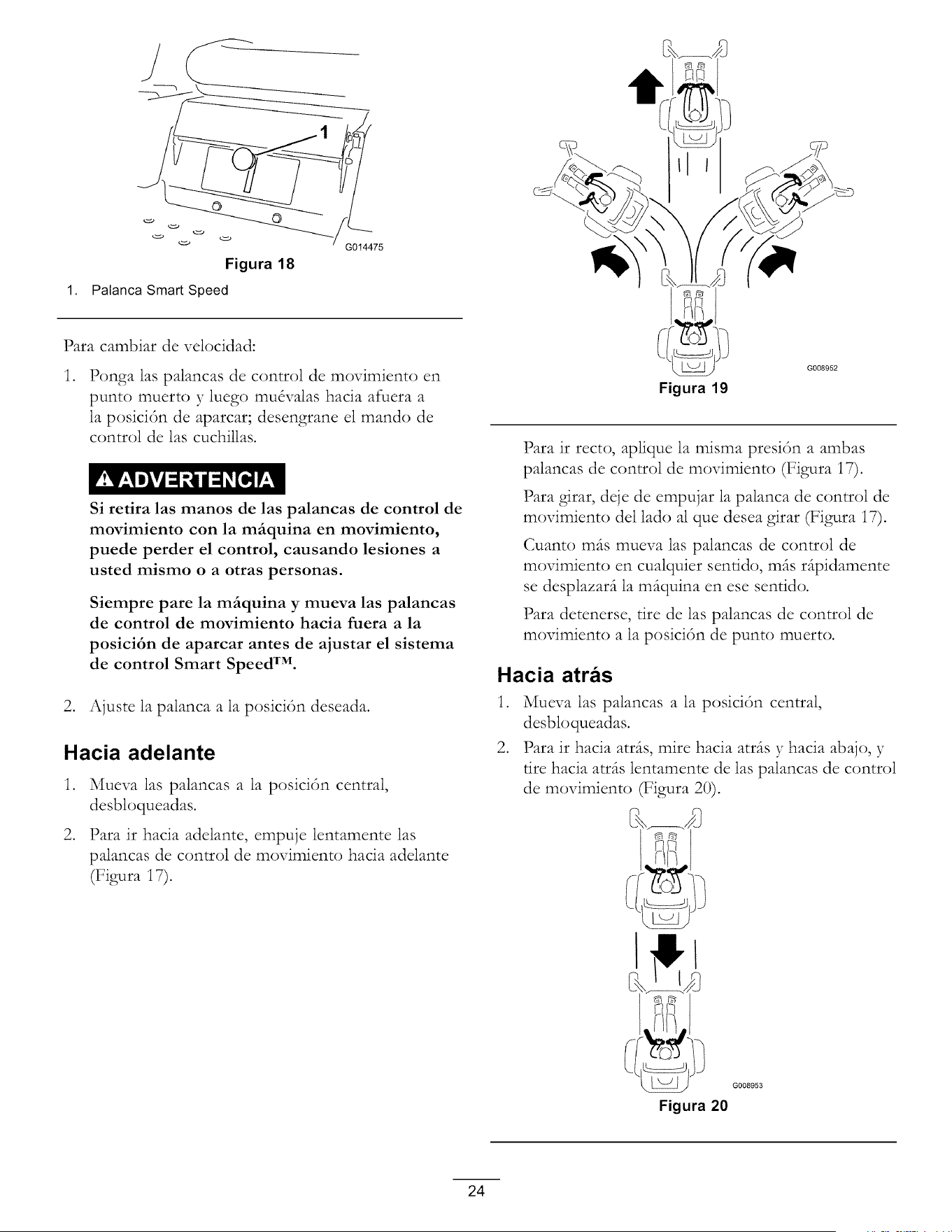
Figura 18
1. Palanca Smart Speed
G014475
Para cambiar de velocidad:
.
Ponga las palancas de control de movimiento en
punto muerto y luego mudvalas hacia afuera a
la posicidn de aparcar; desengrane el mando de
control de las cuchillas.
Si retira las manos de las palancas de control de
movimiento con la mfiquina en movimiento,
puede perder el control, causando lesiones a
usted mismo o a otras personas.
Siempre pare la mfiquina y mueva las palancas
de control de movimiento hacia fuera a la
posici6n de aparcar antes de ajustar el sistema
de control Smart Speed TM.
2. Ajuste la palanca a la posici6n deseada.
Hacia adelante
.
.
Mueva las palancas a la posici6n central,
desbloqueadas.
Para ir hacia adelante, empuje lentamente las
palancas de control de movimiento hacia adelante
(Figura 17).
Figura 19
Para ir recto, aplique la misma presi6n a ambas
palancas de control de movimiento (Figura 17).
Para girar, deje de empujar la palanca de control de
movimiento del lado al que desea girar (Figura 17).
Cuanto m(ts mueva las palancas de control de
movimiento en cualquier sentido, m(ts r(tpidamente
se desplazar(t la m(tquina en ese sentido.
Para detenerse, tire de las palancas de control de
movimiento a la posici6n de punto muerto.
Hacia atras
1. Mueva las palancas a la posici6n central,
desbloqueadas.
2. Para ir hacia atrds, mire hacia atr(ts y hacia abajo, y
tire hacia atr(ts lentamente de las palancas de control
de movimiento (Figura 20).
_ G008953
Figura 20
24
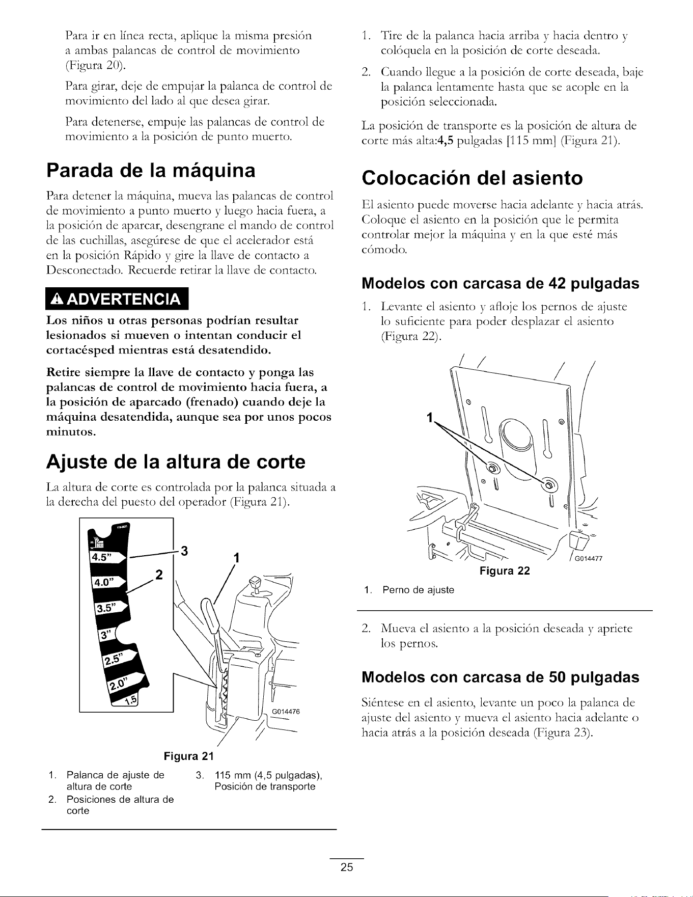
Para ir en l_nea recta, aplique la misma presi6n
a ambas palancas de control de movimiento
(Figura 20).
Para girar, deje de empujar la palanca de control de
movimiento del lado al que desea girar.
Para detenerse, empuje las palancas de control de
movimiento a la posici6n de punt<) muerto.
Parada de la m quina
Para detener la m(tquina, mueva las palancas de control
de movimiento a punto muerto y luego hacia fuera, a
la posici6n de aparcar, desengrane el mando de control
de las cuchillas, asegdrese de que el acelerador est(t
en la posici6n R(tpido y gire la llave de contacto a
Desconectado. Rccuerde retirar la llave de contacto.
Los nifios u otras personas podrian resultar
lesionados si mueven o intentan conducir el
cortac&sped mientras estfi desatendido.
Retire siempre la llave de contacto y ponga las
palancas de control de movimiento hacia fuera, a
la posici6n de aparcado (frenado) cuando deje la
mfiquina desatendida, aunque sea por unos pocos
minutos.
Ajuste de la altura de corte
La altura de cortees controlada pot la palanca situada a
la derecha del puesto del operador (Figura 2i).
.
.
Tire de la palanca hacia arriba }Thacia dentro y
col6quela en la posici6n de corte deseada.
Cuando llegue a la posici6n de corte deseada, baje
la palanca lentamente basra que se acople en la
posici6n seleccionada.
La posici6n de transporte es la posici6n de altura de
corte m_is alta:4,5 pulgadas [115 mm] (Figura 2i).
Colocacibn del asiento
E1 asiento puede moverse hacia adelante y hacia atr(ts.
Coloque el asiento en la posici6n que le permita
controlar mejor la m(tquina y en la que est_ m(ts
c6modo.
Modelos con carcasa de 42 pulgadas
1. Levante el asiento y afloje los pernos de ajuste
lo suficiente para poder desplazar el asiento
(Figura 22).
/
Figura 21
1. Palanca de ajuste de 3.
altura de corte
2. Posiciones de altura de
corte
G014476
115 mm (4,5 pulgadas),
Posici6n de transporte
1. Perno de ajuste
Figura 22
G014477
2. Mueva el asiento a la posici6n deseada y apriete
los pernos.
Modelos con carcasa de 50 pulgadas
Si_ntese en el asiento, levante un poco la palanca de
ajuste del asiento y mueva el asiento hacia adelante o
hacia atr(ts a la posici6n deseada (Figura 23).
25
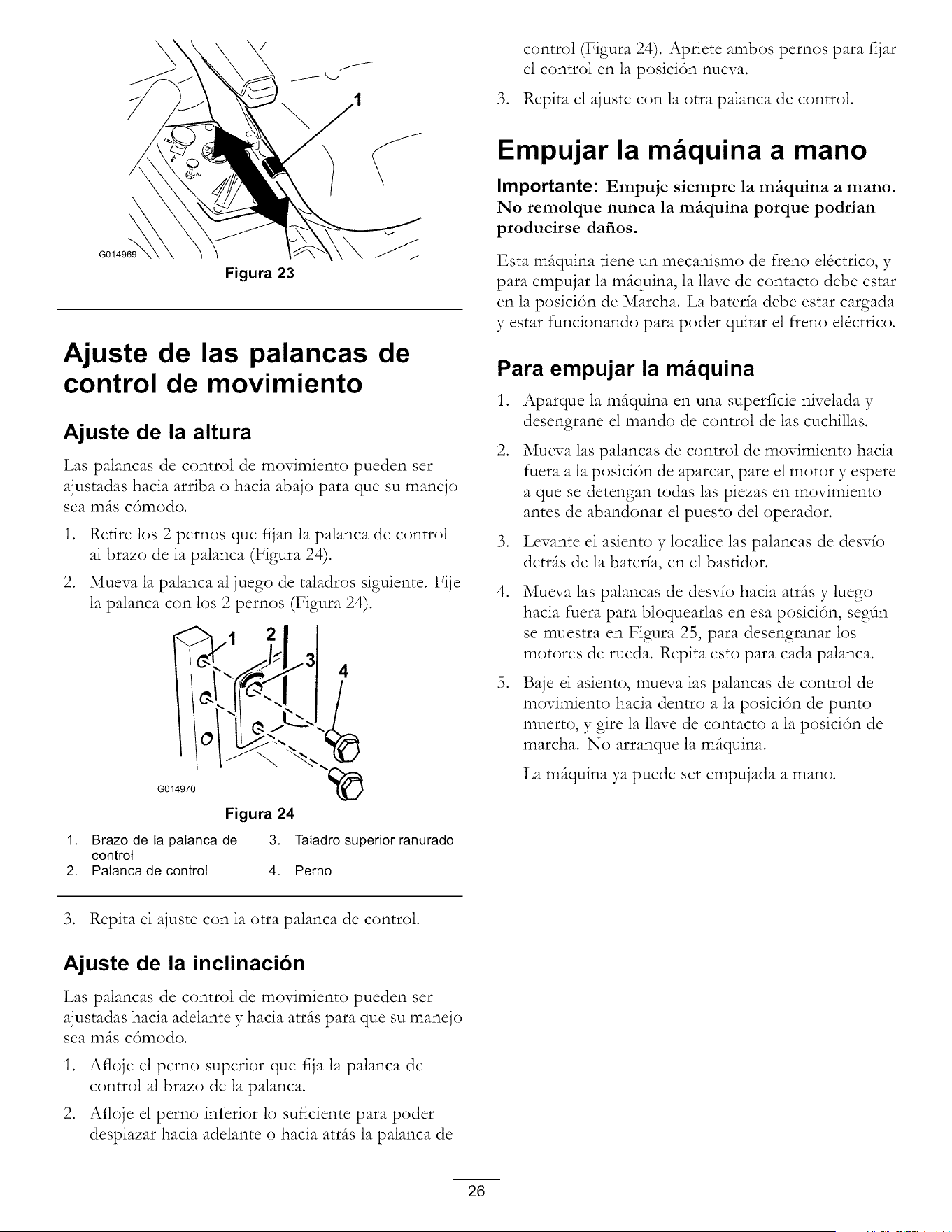
control (Figura 24). Apriete ambos pernos para fijar
el control en la posici6n nueva.
3. Repita el ajuste con la otra palanca de control.
Figura 23
Ajuste de las palancas de
control de movimiento
Ajuste de la altura
Las palancas de control de movimiento pueden set
ajustadas hacia arriba o hacia abajo para que su manejo
sea m(ts c6modo.
1. Retire los 2 pernos que fijan la palanca de control
al brazo de la palanca (Figura 24).
2. Mueva la palanca al juego de taladros siguiente. Fije
la palanca con los 2 pernos (Figura 24).
G014970
1. Brazo de la palanca de 3. Taladro superior ranurado
control
2. Palanca de control 4. Perno
Empujar la m quina a mano
Importante: Empuje siempre la mfiquina a mano.
No remolque nunca la mfiquina porque podrian
producirse dafios.
Esta m(tquina tiene un mecanismo de freno e16ctrico, y
para empujar la m(tquina, la llave de contacto debe estar
en la posici6n de Marcha. La baterfa debe estar cargada
y estar funcionando para poder quitar el freno el6ctrico.
Para empujar la maquina
1. Aparque la mfiquina en una superficie nivelada y
desengrane el mando de control de las cuchillas.
.
Mueva las palancas de control de movimiento hacia
fuera a la posici6n de aparcar, pare el motor y espere
a que se detengan todas las piezas en movimiento
antes de abandonar el puesto del operador.
3. Levante el asiento y localice las palancas de desvio
detrfis de la bater_a, en el basridor.
.
Mueva las palancas de desv{o hacia atrfis y luego
hacia fuera para bloquearlas en esa posici6n, segdn
se muestra en Figura 25, para desengranar los
motores de rueda. Rcpita esto para cada palanca.
,
Baje el asiento, mueva las palancas de control de
movimiento hacia dentro a la posici6n de punt()
muerto, y gire la llave de contacto a la posici6n de
marcha. No arranque la m_quina.
La m_quina ya puede set empujada a man(:).
3. Repita el ajuste con la otra palanca de control.
Ajuste de la inclinacion
Las palancas de control de movimiento pueden set
ajustadas hacia adelante y hacia atr(ts para que su manejo
sea m(ts c6modo.
1. Afloje el perno superior que fija la palanca de
control al brazo de la palanca.
2. Afloje el perno inferior lo suficiente para poder
desplazar hacia adelante o hacia atrfis la palanca de
26
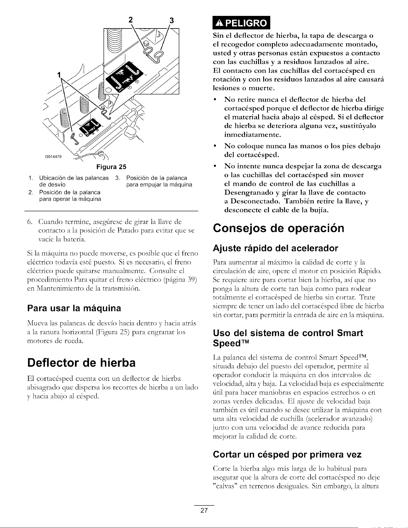
2 3
\
G014479
Figura 25
1. Ubicaci6n de las palancas
de desvio
2. Posici6n de la palanca
para operar la m_quina
3. Posici6n de la patanca
para empujar la m_quina
6. Cuando termine, asegdrese de girar la llave de
contacto a la posici6n de Parado para evitar que se
vacfe la baterfa.
Si la m(tquina no puede moverse, es posible que el freno
el_ctrico todavfa est_ puesto. Si es necesario, el freno
el_ctrico puede quitarse manualmente. Consulte el
procedimiento Para quitar el freno el_ctrico (pdgina 39)
en Mantenimiento de la transmisi6n.
Para usar la maquina
Mueva las palancas de desvfo hacia dentro y hacia atr(ts
a la ranura horizontal (Figura 25) para engranar los
motores de rueda.
Deflector de h ierba
E1 cortac&ped cuenta con un deflector de hierba
abisagrado que dispersa los recortes de hierba a un lad(:)
y hacia abajo al c&ped.
Sin el deflector de hierba, la tapa de descarga o
el recogedor completo adecuadamente montado,
usted y otras personas estfin expuestos a contacto
con las cuchillas y a residuos lanzados al aire.
E1 contacto con las cuchillas del cortac&sped en
rotaci6n y con los residuos lanzados al aire causarfi
lesiones o muerte.
No retire nunca el deflector de hierba del
cortac&sped porque el deflector de hierba dirige
el material hacia abajo al c&sped. Si el deflector
de hierba se deteriora alguna vez, sustit_yalo
inmediatamente.
No coloque nunca las manos o los pies debajo
del cortac&sped.
No intente nunca despejar la zona de descarga
o las cuchillas del cortac_sped sin mover
el mando de control de las cuchillas a
Desengranado y girar la llave de contacto
a Desconectado. Tambi&n retire la llave, y
desconecte el cable de la bujia.
Consejos de operacibn
Ajuste rapido del acelerador
Para aumentar al m(tximo la calidad de corte y la
circulaci6n de aire, opere el motor en posici6n R_ipido.
Se requiere aire para cortar bien la hierba, asf que no
ponga la altura de corte tan baja como para rodear
totalmente el cortac_sped de hierba sin cortar. Trate
siempre de tenet un lad() del cortac&ped libre de hierba
sin cortar, para permirir la entrada de aire en la m(tquina.
Uso del sistema de control Smart
Speed TM
La palanca del sistema de control Smart Speed TM,
situada debajo del puesto del operador, permite al
operador conducir la m(tquina en dos intervalos de
velocidad, alta y baja. La velocidad baja es especialmente
dril para hacer maniobras en espacios estrechos o en
zonas verdes delicadas. E1 ajuste de velocidad baja
tambidn es dtil cuando se desee utilizar la m(tquina con
una alta velocidad de cuchilla (acelerador avanzado)
junto con una velocidad de avance reducida para
mejorar la calidad de corte.
Cortar un cesped por primera vez
Corte la hierba algo m(ts larga de lo habitual para
asegurar que la altura de corte del cortac&ped no deje
" al as"
c v _ en terrenos desiguales. Sin embargo, la altura
27
de corte ud_izada habitualmente suele set la mejor. A1
cortar hierba de m_is de 15 cm (6 pulg.) de alto, suele
set prefcrible cortar el c&ped dos veces para asegurar
una calidad de corte aceptable.
Corte un tercio de la hoja de hierba
Es mejor cortar solamente un tercio aproximadamente
de la hoja de hierba. No se recomienda cortar m(ts, a
menos que la hierba sea escasa o al final del otofio,
cuando la hierba crece m(ts despacio.
Direccion de corte
Alterne la direcci6n de corte para mantener la hierba
erguida. De esta forma tambKn se aFuda a dispersar
mejor los recortes sobre el c&ped y se conseguir(t una
mejor descomposici6n y fcrrilizaci6n.
Corte la hierba a los intervalos
correctos
En general, corte la hierba cada cuatro dias. Pero
recuerde, la hierba crece a velocidades distintas segfin
las temporadas. Pot ello, para mantener la misma altura
de corte, lo cual esfft recomendado, corte el c&ped
con m(ts frecuencia durante la primavera. A medida
que avanza el verano, la velocidad de crecimiento de
la hierba decrece, pot ello debe cortarse con menor
frecuencia. Si no puede cortar la hierba durante un
per{odo prolongado, corte primero con una altura de
corte alta}; despu& de dos dias, xqaelva a cortar con
un ajuste m_is bajo.
Evite cortar demasiado la hierba
Si la anchura de corte del cortac&ped es mayor que la
del cortac&ped que us6 anteriormente, eleve la altura
de corte para asegurarse de no cortar demasiado un
c&ped desigual.
Hierba alta
Si se deja crecer la hierba m_is de lo habitual, o si &ta
condene un grado de humedad elevado, utilice una
altura de corte mayor de lo normal y corte la hierba con
este ajuste. Despu& vueNa a cortar la hierba urilizando
el ajuste habitual.
AI detenerse
Si es necesario detener el avance de la m(tquina mientras
se corta el c&ped, es posible que caiga un mont6n de
recortes sobre el c&ped. Para evitar esto, dirijase a una
zona del c&ped que haya sido segada, con 1as cuchillas
engranadas.
Mantenga limpia la parte inferior del
cortacesped
Limpie los recortes y la suciedad de los bajos del
cortac&ped despu& de cada uso. Si la hierba y la
suciedad se acumulan en el interior del cortac&ped, se
deteriorar(t la calidad del corte.
Mantenimiento de las cuchillas
Mantenga las cuchillas afiladas durante toda la
temporada de corte, ya que una cuchilla afilada corta
limpiamente y sin rasgar o deshilachar las hojas de
hierba. Si se rasgan o se deshilachan, los bordes de
las hojas se secar(m, lo cual retardar(t su crecimiento y
favorecer(t la aparici6n de enfcrmedades. Compruebe
cada Na que las cuchillas de corte esffm afiladas y que
no esffm desgastadas o dafiadas. Elimine cualquier
mella con una lima, y afile las cuchillas si es necesario.
Si una cuchilla est(t desgastada o deteriorada, sustitfiyala
inmediatamente pot una cuchilla nueva genuina Toro.
28
Mantenimiento
Nota: Los lados derecho e izquierdo de la m_quina se determinan desde la posici6n normal del operador.
Calendario recomendado de mantenimiento
Intervalo de manteni-
Procedimiento de mantenimiento
miento y servicio
Despues de las primeras • Cambie el aceite del motor.
8 horas
Cada vez que se utilice
o diariamente
Cada 25 horas
Cada 100 horas
Cada 200 horas
Antes del almacenamiento
• Compruebe el sistema de interruptores de seguridad.
• Compruebe el nivel de aceite del motor.
• Limpie la rejilla de la entrada de aire.
• Compruebe las cuchillas de corte.
• Compruebe que el deflector de hierba no esta deteriorado.
• Limpie la carcasa del cortacesped.
° Lubrique todos los puntos de engrase.
• Compruebe la presi6n de los neumaticos.
• Compruebe que las correas no estan desgastadas ni agrietadas.
• Revise el elemento de papel. (mas a menudo en condiciones de mucho polvo o
suciedad)
• Cambie el aceite del motor. (mas a menudo en condiciones de mucho polvo o
suciedad)
• Compruebe la(s) bujia(s).
• Cambie el filtro de combustible en linea
• Inspeccione el filtro de emisiones.
• Cambie elelemento de papel. (mas a menudo en condiciones de mucho polvo o
suciedad)
• Cambie elfiltro de aceite. (mas a menudo en condiciones de mucho polvo o
suciedad)
• Cargue la bateria y desconecte los cables.
• Realice todos los procedimientos de mantenimiento arriba citados antes del
almacenamiento
• Pinte cualquier superficie desconchada.
Importante: Consuhe en el manual del operador del motor procedimientos adicionales de mantenimiento.
Si deja la llave en el interruptor de encendido, alguien podria arrancar el motor accidentalmente y causar
lesiones graves a usted o a otras personas.
Retire la llave del interruptor de encendido y desconecte el cable de la bujia antes de realizar cualquier
operaci6n de mantenimiento. Aparte el cable para evitar su contacto accidental con la bujia.
29
Procedimientos previos
al mantenimiento
Cbmo levantar el asiento
Asegdrese de que las palancas de control de movimiento
estfin bloqueadas en la posici6n de aparcar. Mueva el
asiento hacia adelante.
Es posible acceder a los siguientes componentes
levantando el asiento:
• Placa de ndmero de serie
• Pegatina de mantenimiento
• Pernos de ajuste del asiento
• Filtro de combustible
• Bateda y cables
Lubricaci6n
Engrasado de los cojinetes
Intervalo de mantenimiento: Cada 25
horas--Lubrique todos los puntos de
engrase.
Tipo de grasa: Grasa de lid(:) de prop6sito general N ° 2.
.
.
.
Aparque la m_tquina en una superficie nivelada y
desengrane el mando de control de las cuchillas.
Mueva las palancas de control de movimiento hacia
fuera a la posici6n de aparcar, pare el motor, retire
la llave y espere a que se detengan todas las piezas
en movimiento antes de abandonar el puesto del
operador.
Limpie con un trap(:) los puntos de engrase (Figura 26
y Figura 27). Asegdrese de rascar cualquier pintura
que hubiera sobre los puntos de engrase.
1,
Figura 26
Rueda giratoria delantera
G014522
Figura 27
Ubicada debajo del asiento
1. Lea las instrucciones
antes de reatizar
cuatquier operaci6n de
mantenimiento o ajuste.
2. Compruebe ta presi6n
de los neum_ticos cada
25 horas de operaci6n.
3. Engrase cada 25 horas de
operaci6n.
4. Motor
3O
.
Conecte una pistola de engrasar a cada punt(:) de
engrase (Figura 26 y Figura 27). Bombee grasa hasta
que empiece a rezumar grasa de los cojinetes.
5. Limpie cualquier exceso de grasa.
Mantenimiento del motor
Mantenimiento del limpiador
de aire
Nota: Haga el mantenimiento del limpiador de aire con
mayor frecuencia (despuds de pocas horas) si el entorno
de trabajo tiene much(:) polvo o arena.
Como retirar el elemento
.
.
.
.
Aparque la m_tquina en una superficie nivelada y
desengrane el control de las cuchillas _TO).
Mueva las palancas de control de movimiento a
la posici6n de frenado, pare el motor, retire la
llave y espere a que se detengan todas las piezas
en movimiento antes de abandonar el puesto del
operador.
Limpie alrededor de la tapa del hmpiador de aire para
evitar que la suciedad penetre en el motor y cause
dafios. Levante la cubierta y retire la abrazadera que
sujeta el conjunto del limpiador de aire al motor
(Figura 28).
Afloje la abrazadera y retire el element(:) de
papel(Figura 28).
$014908
Figura 28
1. Tapa 3. Abrazadera
2. Elemento de papel
Limpieza del elemento
Intervalo de mantenimiento: Cada i 00 horas--Revise
el element() de papel. (m_is a menudo
en condiciones de much() polvo o
suciedad)
31
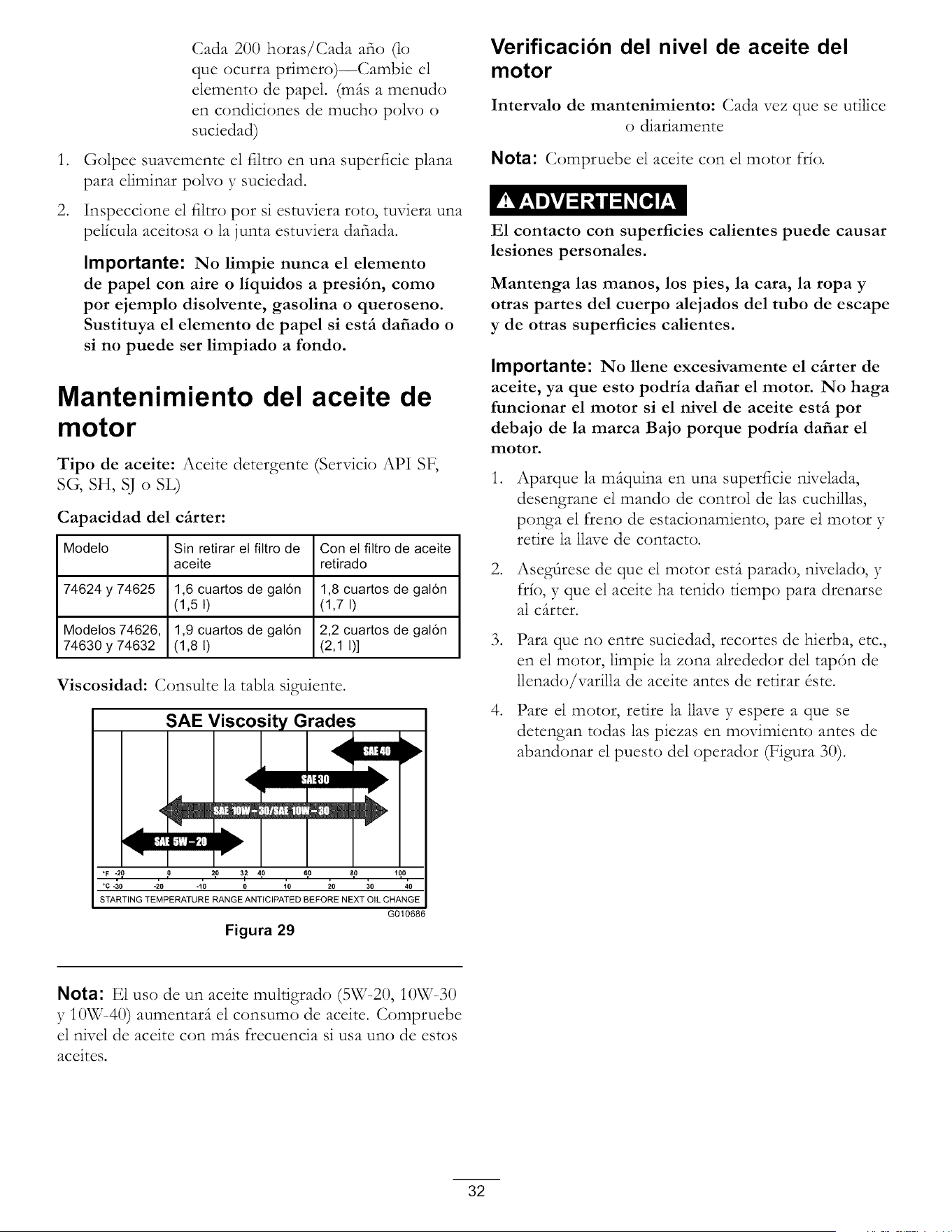
.
.
Cada 200 horas/Cada afio (lo
que ocurra primero)--Cambie el
elemento de papel. (mils a menudo
en condiciones de mucho poNo o
suciedad)
Golpee suavemente el filtro en una superficie plana
para eliminar polvo y suciedad.
Inspeccione el filtro pot si estuviera roto, tuviera una
pel{cula aceitosa o la junta estuviera dafiada.
Importante: No limpie nunca el elemento
de papel con aire o liquidos a presi6n, como
por ejemplo disolvente, gasolina o queroseno.
Sustituya el elemento de papel si estfi dafiado o
si no puede ser limpiado a rondo.
Modelo
74624 y 74625
Modetos 74626,
74630 y 74632
Manten
motor
Tipo de aceite: Aceite detergente
SG, SH, SJ o SL)
Capacidad del cfirter:
Sin retirar el filtro de
aceite
1,6 cuartos de gal6n
(1,5 I)
1,9 cuartos de gal6n
(1,8 I)
imiento del aceite de
'Servicio API SF,
Con et filtro de aceite
retirado
1,8 cuartos de gat6n
(1,7 I)
2,2 cuartos de gat6n
(2,1 I)]
Viscosidad: Consulte la tabla sigu_ente.
SAE Viscosity Grades
|_]
<
i!_tl]
°F -20 0 20 32 40 60 80 100
°C -30 -20 -10 0 10 20 30 40
STARTING TEMPERATURE RANGE ANTICIPATED BEFORE NEXT OIL CHANGE
G010686
Figura 29
Verificacion del nivel de aceite del
motor
Intervalo de mantenimiento: Cada vez que se utilice
o diariamente
Nota: Compruebe el aceite con el motor fdo.
E1 contacto con superficies calientes puede causar
lesiones personales.
Mantenga las manos, los pies, la cara, la ropa y
otras partes del cuerpo alejados del tubo de escape
y de otras superficies calientes.
Importante: No llene excesivamente el cfirter de
aceite, ya que esto podria dafiar el motor. No haga
funcionar el motor si el nivel de aceite estfi por
debajo de la marca Bajo porque podria dafiar el
motor.
.
.
.
°
Aparque la mfiquina en una superficie nivelada,
desengrane el mando de control de las cuchillas,
ponga el freno de estacionamiento, pare el motor y
retire la llave de contact().
Asegfirese de que el motor estfi parado, nivelado, y
fdo, y que el aceite ha tenido tiempo para drenarse
al critter.
Para que no entre suciedad, recortes de hierba, etc.,
en el motor, limpie la zona alrededor del tap6n de
llenado/varilla de aceite antes de retirar dste.
Pare el motor, retire la llave y espere a que se
detengan todas las piezas en movimiento antes de
abandonar el puesto del operador (Figura 30).
Nota: E1 uso de un aceite muldgrado (5W=20, IOW-30
y IOW-40) aumentarfi el consumo de aceite. Compruebe
el nivel de aceite con mils frecuencia si usa uno de estos
aceites.
32
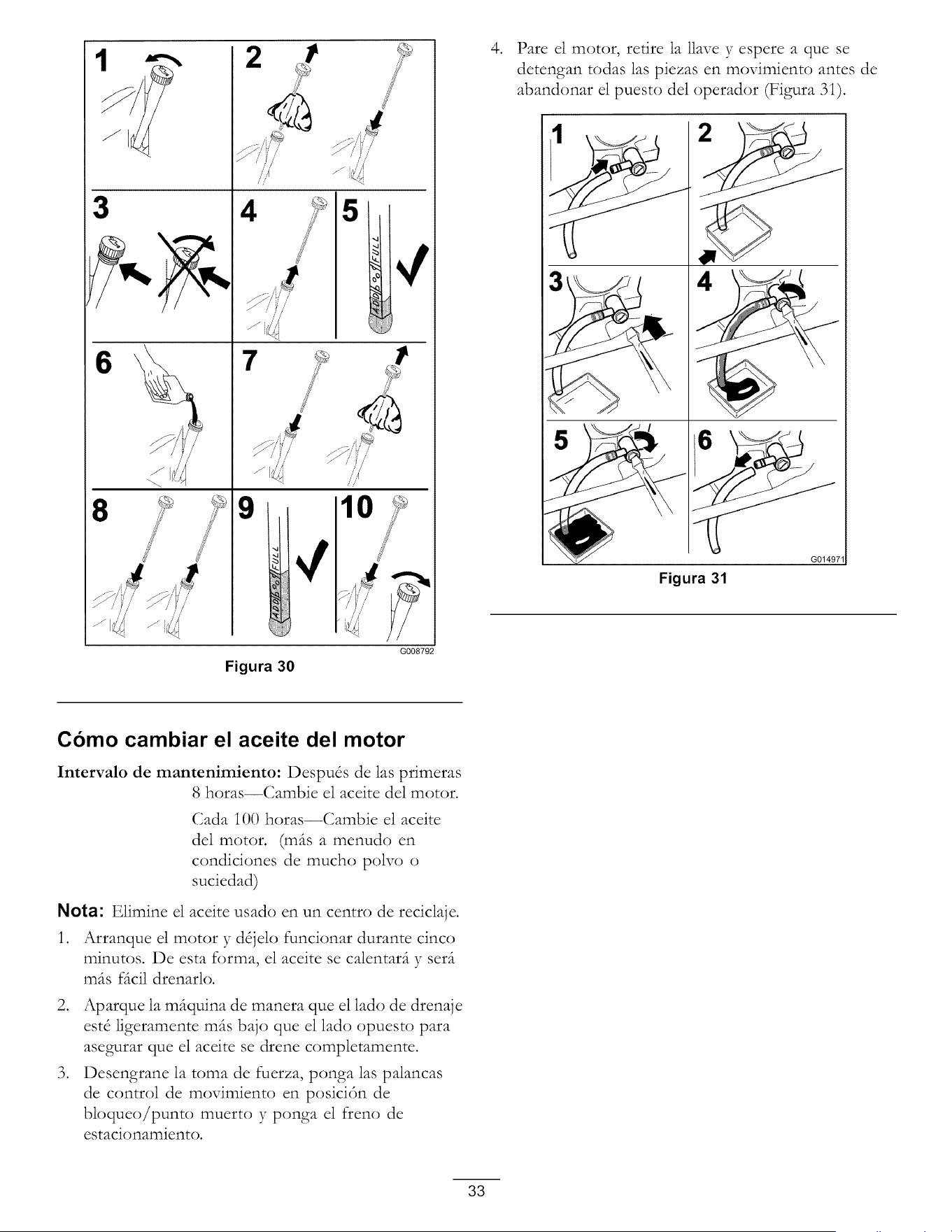
3
8
6
i/
4 5
m
M'
J,
/ _/,,, /,,,_
I'°
G008792
Figura 30
.
Pare el motor, retire la llave y espere a que se
detengan todas las piezas en movimiento antes de
abandonar el puesto del operador (Figura 3i).
Figura 31
G01497"
Como cambiar el aceite del motor
Intervalo de mantenimiento: Despu& de las primeras
8 horas--Cambie el aceite del motor.
Cada i00 horas--Cambie el aceite
del motor. (m_ts a menudo en
condiciones de much(:) polvoo
suciedad)
Nota: Elimine el aceite usado en un centro de reciclaje.
1. Arranque el motor y d_jelo funcionar durante cinco
minutos. De esta forma, el aceite se calentar(t y ser(t
m_ts fdcil drenarlo.
2. Aparque la m_tquina de manera que el lad() de drenaje
est_ ligeramente m_ts bajo que el lad() opuesto para
asegurar que el aceite se drene completamente.
3. Desengrane la toma de fuerza, ponga las palancas
de control de movimiento en posici6n de
bloqueo/punto muerto y ponga el freno de
estacionamiento.
33
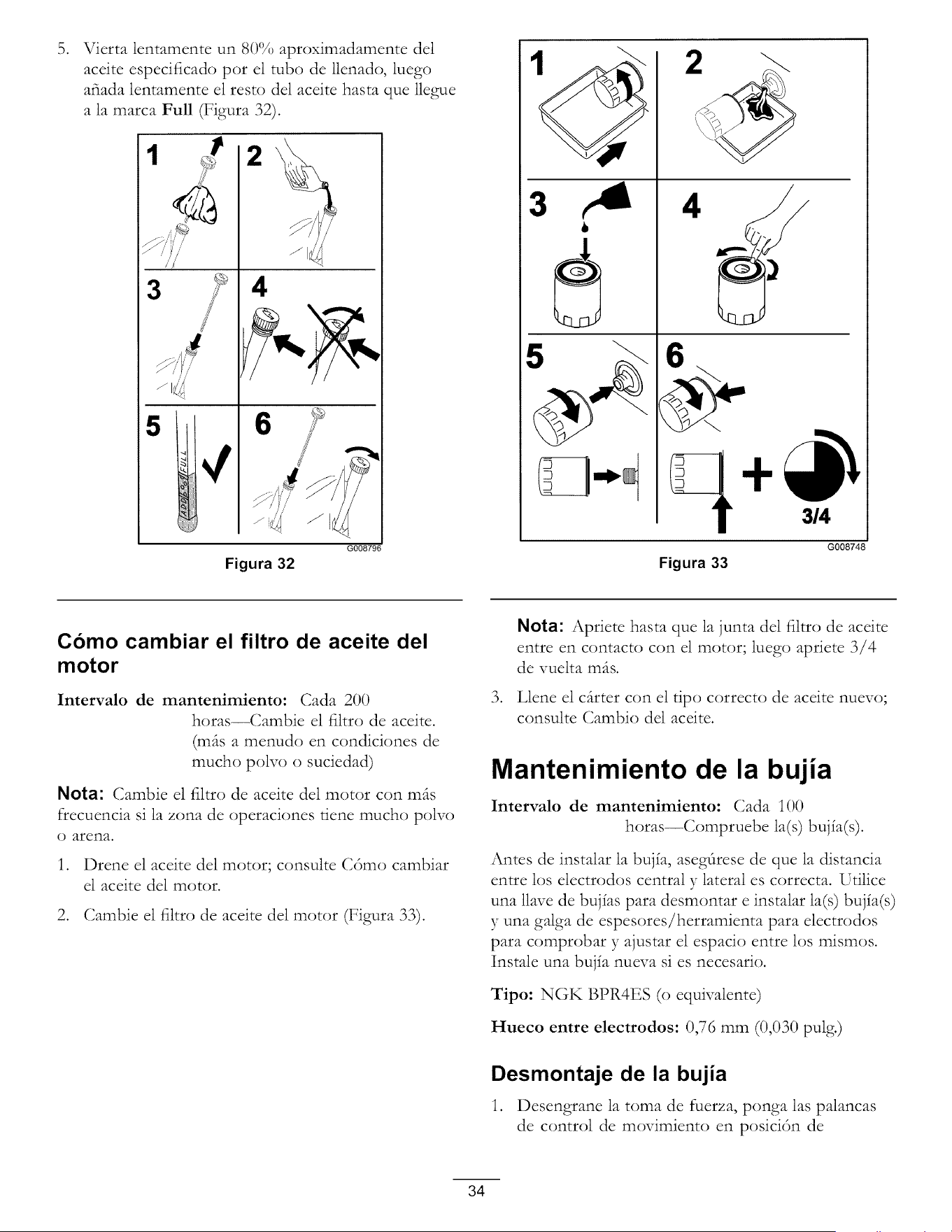
.
Vierta lentamente un 80% aproximadamente del
aceite especificado por el tubo de llenado, luego
afiada lentamente el resto del aceite hasta que lle_ue
a la marca Full (Figura 32).
1
3
5
2
4
Figura 32
G008796
3
2
6_
q
Figura 33
3/4
G008748
Como cambiar el filtro de aceite del
motor
Intervalo de mantenimiento: Cada 200
horas--Cambie el film) de aceite.
(mils a menudo en condiciones de
much(;) polvo o suciedad)
Nota: Cambie el filtro de aceite del motor con mils
frecuencia si la zona de operaciones tiene much(;) polvo
o arena.
1. Drene el aceite del motor; consulte C6mo cambiar
el aceite del motor.
2. Cambie el filtro de aceite del motor (Figura 33).
.
Nota: Apriete hasta que la junta del filtro de aceite
entre en contacto con el motor; luego apriete 3/4
de vuelta mils.
Llene el critter con el tip() correcto de aceite nuevo;
consulte Cambio del aceite.
Mantenimiento de la bujia
Intervalo de mantenimiento: Cada i00
horas--Compruebe la(s) bujia(s).
Antes de instalar la bujia, aseg_rese de que la distancia
entre los electrodos central y lateral es correcta. Utilice
una llave de bujias para desmontar e instalar la(s) bujia(s)
y una galga de espesores/herramienta para electrodos
para comprobar y ajustar el espacio entre los mismos.
Instale una bujia nueva si es necesario.
Tipo: NGK BPR4ES (o equivalente)
Hueco entre electrodos: 0,76 mm (0,030 pulg.)
Desmontaje de la bujia
1. Desengrane la toma de fuerza, ponga las palancas
de control de movimiento en posici6n de
34
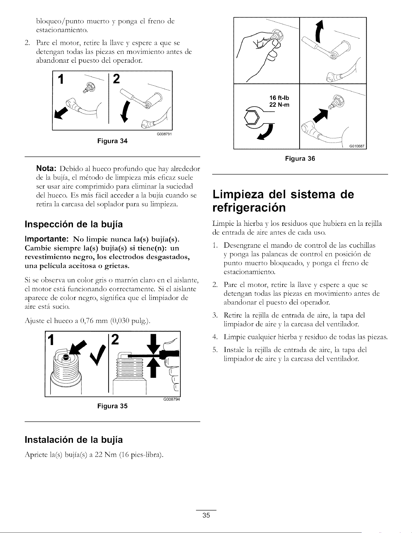
.
bloqueo/punto muerto y ponga el ffeno de
estacionamiento.
Pare el motor, retire la llave y espere a que se
detengan todas las piezas en movimiento antes de
abandonar el puesto del operador.
Figura 34
G008791
Nota: Debido al hueco profundo que hay alrededor
de la bujfa, el m&odo de limpieza mils eficaz suele
set usar aire comprimido para eliminar la suciedad
del hueco. Es mils fdcil acceder a la bujfa cuando se
redra la carcasa del soplador para su limpieza.
Inspeccion de la bujia
Importante: No limpie nunca la(s) bujia(s).
Cambie siempre la(s) bujia(s) si tiene(n): un
revestimiento negro, los electrodos desgastados,
una pelicula aceitosa o grietas.
Si se observa un color gris o marr6n claro en el aislante,
el motor estfi funcionando correctamente. Si el aislante
aparece de cok)r negro, significa que el limpiador de
aire estfi sucio.
Ajuste el hueco a 0,76 mm (0,030 pulg.).
Figura 35
G008794
16 ft-lb
_/ 22 N-m
G010687
Figura 36
Limpieza del sistema de
refrigeracibn
Limpie la hierba y los residuos que hubiera en la rejilla
de entrada de aire antes de cada us(:).
.
Desengrane el mando de control de las cuchillas
y ponga las palancas de control en posici6n de
punt(:) muerto bloqueado, y ponga el freno de
estacionamiento.
.
.
°
5.
Pare el motor, retire la llave y espere a que se
detengan todas las piezas en movimiento antes de
abandonar el puesto del operador.
Retire la rejilla de entrada de aire, la tapa del
limpiador de aire y la carcasa del vendlador.
Limpie cualquier hierba y residuo de todas las piezas.
Instale la rejilla de entrada de aire, la tapa del
limpiador de aire y la carcasa del vendlador.
Instalacion de la bujia
Apriete la(s) buj_a(s) a 22 Nm (16 pies-libra).
35
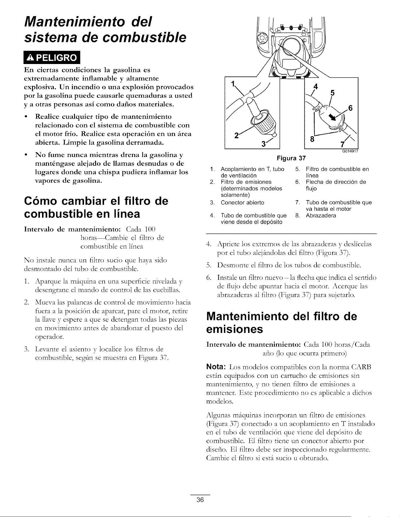
Mantenimiento del
sistema de combustible
En ciertas condiciones la gasolina es
extremadamente inflamable y altamente
explosiva. Un incendio o una explosi6n provocados
por la gasolina puede causarle quemaduras a usted
y a otras personas asi como dafios materiales.
Realice cualquier tipo de mantenimiento
relacionado con el sistema de combustible con
el motor frio. Realice esta operaci6n en un firea
abierta. Limpie la gasolina derramada.
No fume nunca mientras drena la gasolina y
mant_ngase alejado de llamas desnudas o de
lugares donde una chispa pudiera inflamar los
vapores de gasolina.
Cbmo cambiar el filtro de
combustible en linea
Intervalo de mantenimiento: Cada i00
horas--Cambie el filtro de
combustible en lfnea
No instale nunca un filtro sucio que haya sido
desmontado del tub(:) de combustible.
.
.
.
Aparque la mfiquina en una superficie nivelada y
desengrane el mando de control de las cuchillas.
Mueva las palancas de control de movimiento hacia
fuera a la posicidn de aparcar, pare el motor, retire
la llave y espere a que se detengan todas las piezas
en movimiento antes de abandonar el puesto del
operador.
Levante el asiento y localice los filtros de
combustible, segdn se muestra en Figura 37.
1,
2.
3,
4.
Figura 37
4
5
8
7
G014917
Acoplamiento en T, tubo 5. Filtro de combustible en
de ventilacidn linea
Fittro de emisiones 6. Ftecha de direccidn de
(determinados modetos fiujo
solamente)
Conector abierto 7. Tubo de combustible que
va hasta et motor
Tubo de combustible que 8. Abrazadera
viene desde el depdsito
.
.
6.
Apriete los extremos de las abrazaderas y deslicelas
pot el tub(:) alejdndolas del filtro (Figura 37).
Desmonte el filtro de los tubos de combustible.
Instale un filtro nuevo - la flecha que indica el sentido
de flujo debe apuntar hacia el motor. Acerque las
abrazaderas al filtro (Figura 37) para sujetarlo.
Mantenimiento del filtro de
emisiones
Intervalo de mantenimiento: Cada 100 horas/Cada
aft(:) (lo que ocurra primer(:))
Nota: Los modelos compatibles con la norma CARB
estfin equipados con un cartucho de emisiones sin
mantenimiento, y no tienen filtro de emisiones a
mantener. Este procedimiento no es aplicable a dichos
modelos.
Algunas mfiquinas incorporan un filtro de emisiones
(Figura 37) conectado a un acoplamiento en T instalado
en el tub() de ventilacidn que viene del depdsito de
combustible. E1 filtro tiene un conector abierto pot
disefio. E1 filtro debe set inspeccionado regularmente.
Cambie el filtro si estfi sucio u obturado.
36
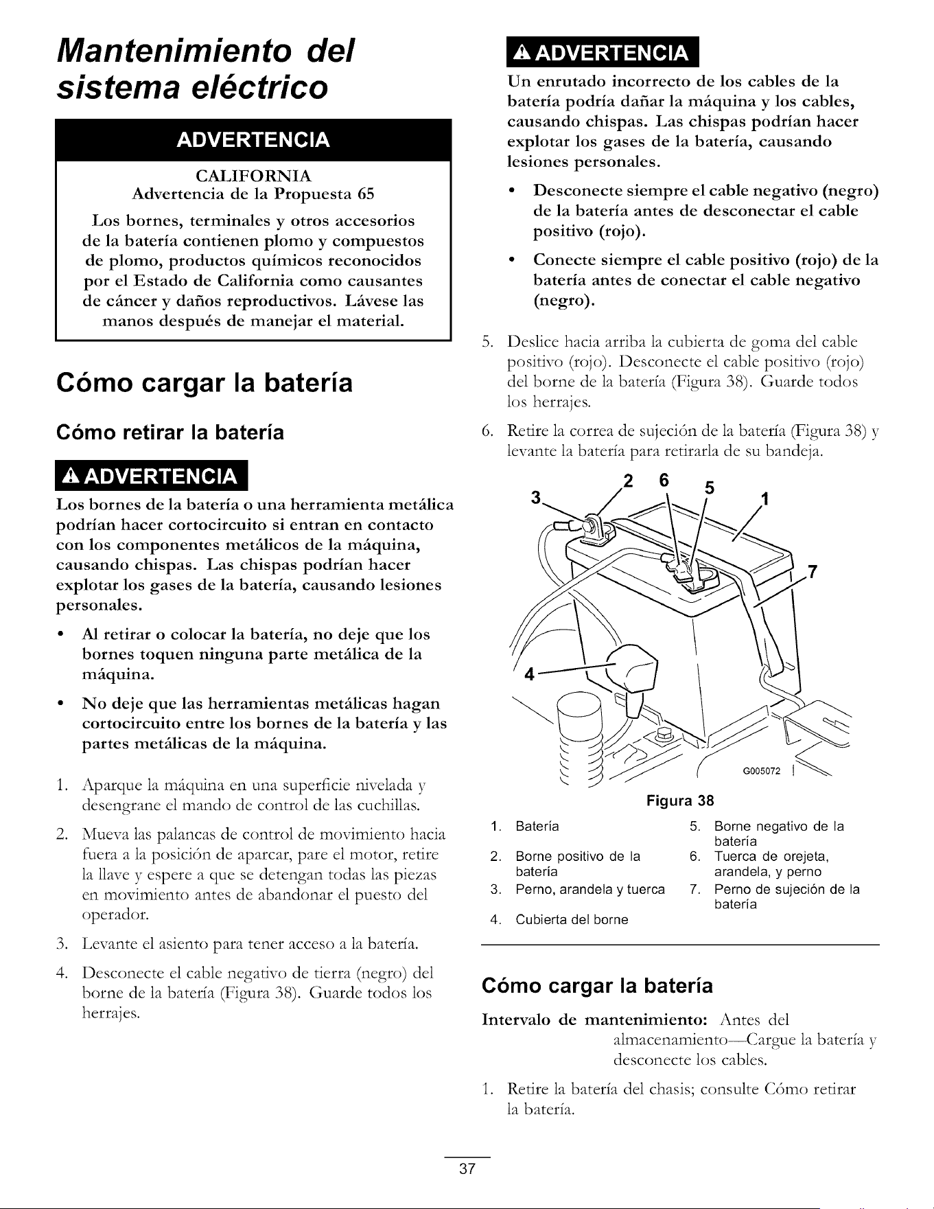
Mantenimiento del
sistema el ctrico
CALIFORNIA
Advertencia de la Propuesta 65
Los bornes, terminales y otros accesorios
de la bateria contienen plomo y compuestos
de plomo, productos quimicos reconocidos
por el Estado de California como causantes
de cfincer y dafios reproductivos. Lfivese las
manos despu_s de manejar el material.
Cbmo cargar la bateria
Como retirar la bateria
Los bornes de la bateria o una herramienta metfilica
podrian hacer cortocircuito si entran en contacto
con los componentes metfilicos de la mfiquina,
causando chispas. Las chispas podrian hacer
explotar los gases de la bateria, causando lesiones
personales.
• AI retirar o colocar la bateria, no deje que los
bornes toquen ninguna parte metfilica de la
mfiquina.
• No deje que las herramientas metfilicas hagan
cortocircuito entre los homes de la bateria y las
partes metfilicas de la mfiquina.
.
.
.
4.
Aparque la m_quina en una superficie nivelada y
desengrane el mando de control de las cuchillas.
Mueva las palancas de control de movimiento hacia
fuera a la posici6n de aparcar, pare el motor, retire
la llave y espere a que se detengan todas las piezas
en movimiento antes de abandonar el puesto del
operador.
Levante el asiento para tenet acceso a la baterfa.
Desconecte el cable negativo de tierra (negro) del
borne de la baterfa (Figura 38). Guarde todos los
herrajes.
.
°
Un enrutado incorrecto de los cables de la
bateria podria dafiar la mfiquina y los cables,
causando chispas. Las chispas podrian hacer
explotar los gases de la bateria, causando
lesiones personales.
• Desconecte siempre el cable negativo (negro)
de la bateria antes de desconectar el cable
positivo (rojo).
• Conecte siempre el cable positivo (rojo) de la
bateria antes de conectar el cable negativo
(negro).
Deslice hacia arriba la cubierta de goma del cable
positivo (rojo). Desconecte el cable positivo (rojo)
del borne de la baterfa (Figura 38). Guarde todos
los herrajes.
Retire la correa de sujeci6n de la baterfa (Figura 38) y
levante la baterfa para retirarla de su bandeja.
2 6
5
G005072
Figura 38
1. Bateria 5. Borne negativo de la
bateria
2. Borne positivo de la 6. Tuerca de orejeta,
bateria arandeta, y perno
3. Perno, arandela y tuerca 7. Perno de sujeci6n de la
bateria
4. Cubierta del borne
Como cargar la bateria
Intervalo de mantenimiento: Antes del
almacenamiento--Cargue la baterfa y
desconecte los cables.
1. Retire la baterfa del chasis; consulte C6mo retirar
la baterfa.
37
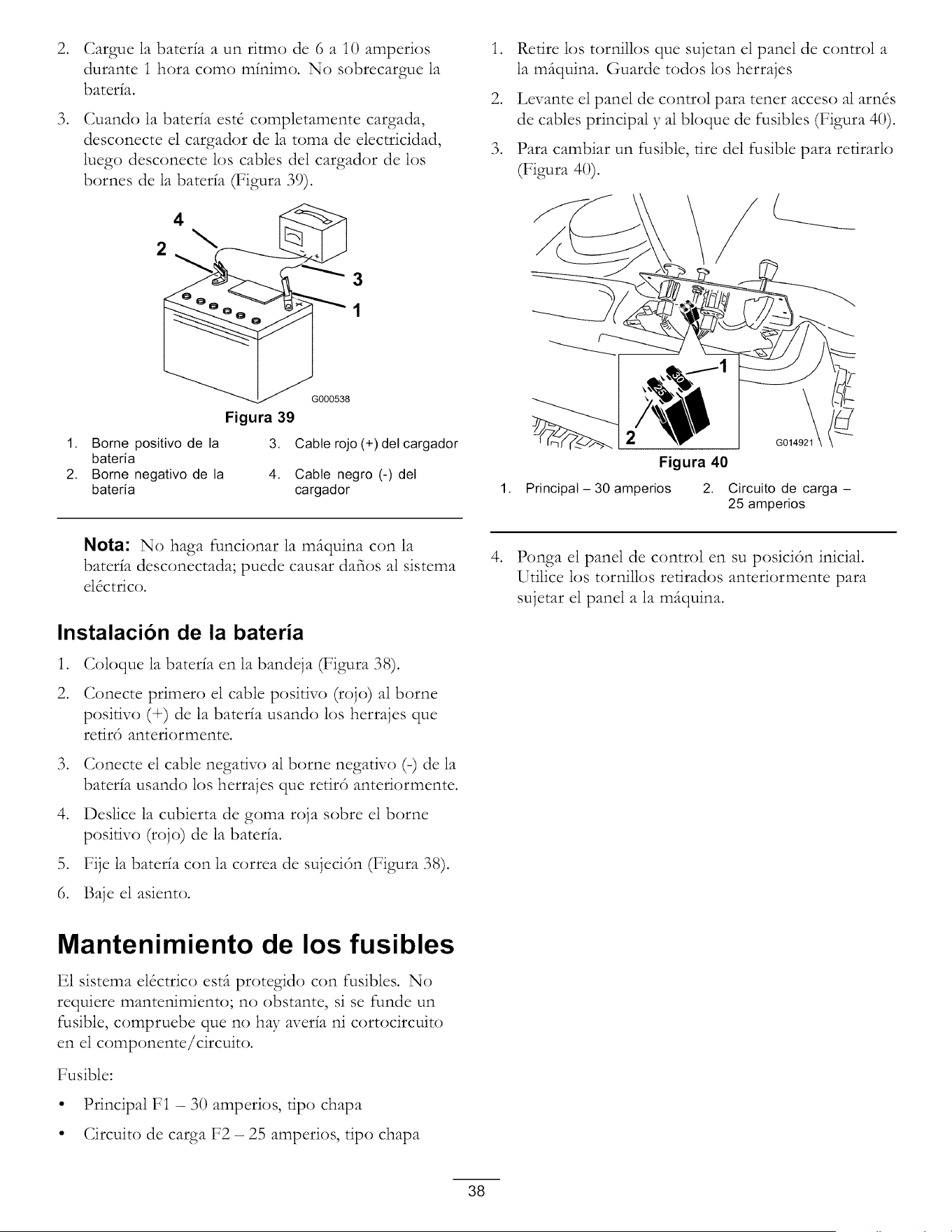
+
+
Cargue la bateda a un ritmo de 6 a 10 amperios
durante 1 hora como mfnimo. No sobrecargue la
bateda.
Cuando la bater{a est_ completamente cargada,
desconecte el cargador de la toma de electricidad,
luego desconecte los cables del cargador de los
bornes de la bateda (Figura 39).
2
3
1
G000538
Figura 39
1. Borne positivo de la 3. Cable rojo (+)del cargador
bateria
2. Borne negativo de la 4. Cable negro (-) det
bateria cargador
°
°
°
Retire los tornillos que sujetan el panel de control a
la m(tquina. Guarde todos los herrajes
Levante el panel de control para tener acceso al am&
de cables principal y al bloque de fusibles (Figura 40).
Para cambiar un fusible, tire del fusible para redrarlo
(Figura 40).
1,
Figura 40
Principal - 30 amperios 2. Circuito de carga -
25 amperios
Nota: No haga funcionar la mfiquina con la
bateda desconectada; puede causar dafios al sistema
el&trico.
Instalacion de la bateria
°
2.
Coloque la bateda en la bandeja (Figura 38).
Conecte primero el cable posidvo (rojo) al borne
positivo (4-) de la bater{a usando los herrajes que
retir6 anteriormente.
°
°
Conecte el cable negativo al borne negativo (-) de la
bateda usando los herrajes que retir6 anteriormente.
Desiice la cubierta de goma roja sobre el borne
posidvo (rojo) de la bateda.
5. Fije la bater{a con la correa de sujeci<Sn (Figura 38).
6. Baje el asiento.
°
Ponga el panel de control en su posici6n inicial.
Utilice los tornillos redrados anteriormente para
sujetar el panel a la m(tquina.
Mantenimiento de los fusibles
E1 sistema el&trico estfi protegido con fusibles. No
requiere mantenimiento; no obstante, si se funde un
fusible, compruebe que no hay aveda ni cortocircuito
en el componente/circuito.
Fusible:
• Principal FI - 30 amperios, tipo chapa
• Circuito de carga F2 - 25 amperios, tipo chapa
38
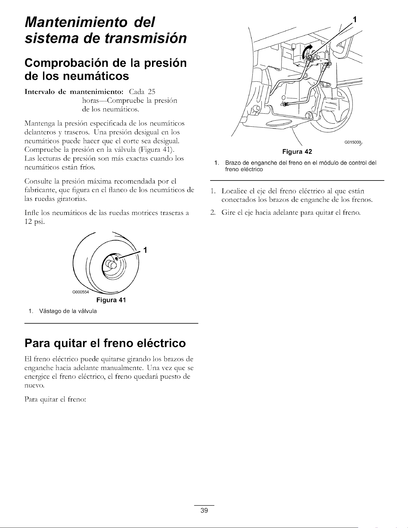
Mantenimiento del
sistema de transmisi6n
Comprobacibn de la presibn
de los neumfiticos
Intervalo de mantenimiento: Cada 25
horas--Compruebe la presi6n
de los neum(tticos.
Mantenga la presi6n especificada de los neum_tticos
delanteros y traseros. Una presi6n desigual en los
neum(tticos puede hacer que el corte sea desigual.
Compruebe la presi6n en la vdlxqala (Figura 4i).
Las lecturas de presi6n son m(ts exactas cuando los
neum(tticos est(m frfos.
Consulte la presi6n m(txima recomendada pot el
fabricante, que figura en el flanco de los neum(tticos de
las ruedas giratorias.
Infle los neum(tticos de las ruedas mortices traseras a
12 psi.
G000554
Figura 41
1. Vfistago de la vfilvula
1,
,
G015000/
Figura 42
Brazo de enganche del freno en el m6dulo de control del
freno el6ctrico
Localice el eje del freno el&trico al que esdm
conectados los brazos de enganche de los frenos.
2. Gire el eje hacia adelante para quitar el freno.
Para quitar el freno eldctrico
E1 freno el&trico puede quitarse girando los brazos de
enganche hacia adelante manualmente. Una vez que se
energice el freno el_ctrico, el freno quedar(t puesto de
nuevo.
Para quitar el freno:
39
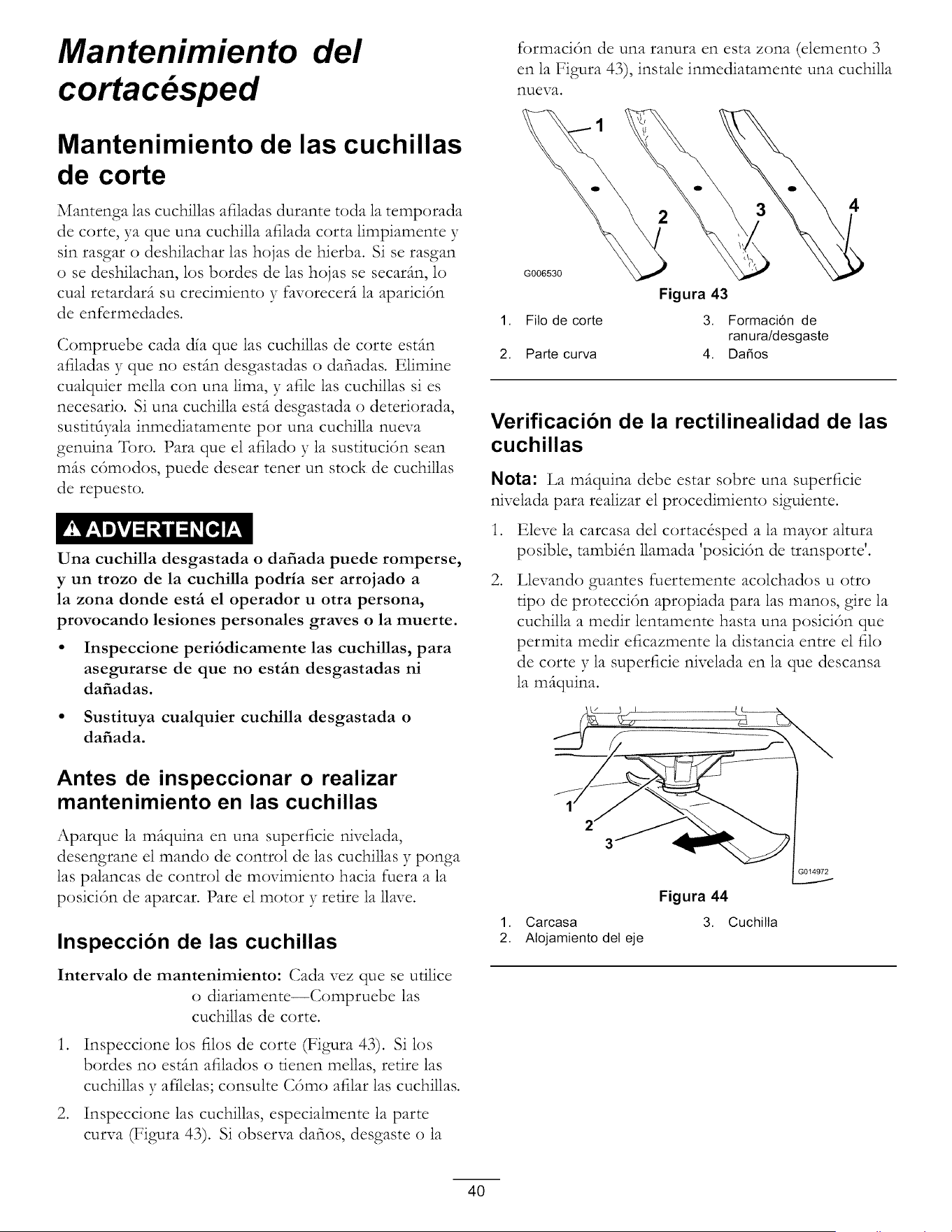
Mantenimiento
cortac sped
del
Mantenimiento de las cuchillas
de corte
Mantenga las cuchillas afiladas durante toda la temporada
de corte, ya que una cuchilla afilada corta limpiamente y
sin rasgar o deshilachar las hojas de hierba. Si se rasgan
o se deshilachan, los bordes de las hojas se secar_m, lo
cual retardar(t su crecimiento y favorecer(t la aparici6n
de enfcrmedades.
Compruebe cada dfa que las cuchillas de corte esdm
afiladas y que no esdm desgastadas o dafiadas. Elimine
cualquier mella con una lima, y afile las cuchillas si es
necesario. Si una cuchilla est(t desgastada o deteriorada,
sustitdyala inmediatamente pot una cuchilla nueva
genuina Toro. Para que el afilado y la sustituci6n sean
m_ts c6modos, puede desear tenet un stock de cuchillas
de repuesto.
Una cuchilla desgastada o dafiada puede romperse,
y un trozo de la cuchilla podria ser arrojado a
la zona donde estfi el operador u otra persona,
provocando lesiones personales graves o la muerte.
• Inspeccione peri6dicamente las cuchillas, para
asegurarse de que no estfin desgastadas ni
dafiadas.
• Sustituya cualquier cuchilla desgastada o
dafiada.
Antes de inspeccionar o realizar
mantenimiento en las cuchillas
Aparque la mdquina en una superficie nivelada,
desengrane el mando de control de las cuchillas y ponga
las palancas de control de movimiento hacia fuera a la
posici6n de aparcar. Pare el motor y retire la llave.
Inspeccion de las cuchillas
Intervalo de mantenimiento: Cada vez que se udlice
o diariamente--Compruebe las
cuchillas de corte.
.
.
Inspeccione los filos de corte (Figura 43). Si los
bordes no esdm afilados o tienen mellas, retire las
cuchillas y afflelas; consulte C6mo afilar las cuchillas.
Inspeccione las cuchillas, especialmente la parte
curva (Figura 43). Si observa dafios, desgaste o la
formaci6n de una ranura en esta zona (element() 3
en la Figura 43), instale inmediatamente una cuchilla
nueva.
2
G006530
4
Figura 43
1. Filo de corte 3. Formaci6n de
ran ura/d esgaste
2. Parte curva 4. Dafios
Verificacion de la rectilinealidad de las
cuchillas
Nota: La m_iquina debe estar sobre una superficie
nivelada para realizar el procedimiento siguiente.
.
.
Eleve la carcasa del cortac&ped a la mayor altura
posible, tambidn llamada posici6n de transporte.
Llevando guantes fuertemente acolchados u otto
tipo de protecci6n apropiada para las manos, gire la
cuchilla a medir lentamente basra una posici6n que
permita medir eficazmente la distancia entre el filo
de corte y la superficie nivelada en la que descansa
la m(tquina.
Figura 44
1. Carcasa 3. Cuchilla
2. Alojamiento det eje
4O
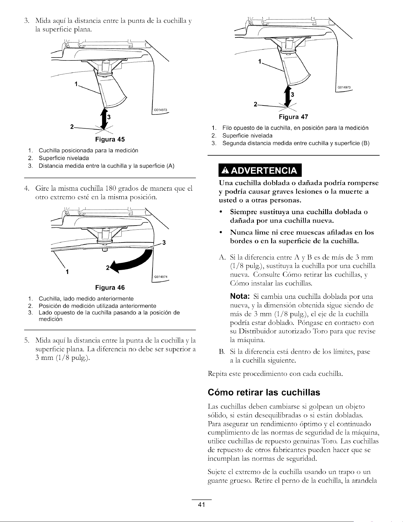
.
Mida aquf la distancia entre la punta de la cuchilla y
la superficie plana.
}014973
.
.
G014973
Figura 45
1. Cuchilta posicionada para la medici6n
2. Superficie nivetada
3. Distancia medida entre la cuchilla y la superficie (A)
Gire la misma cuchilla i80 grados de manera que el
otto extremo est_ en la misma posici6n.
Figura 46
1. Cuchilla, lado medido anteriormente
2. Posici6n de medici6n utilizada anteriormente
3. Lado opuesto de la cuchilla pasando a la posici6n de
medici6n
Mida aquf la distancia entre la punta de la cuchilla y la
superficie plana. La difcrencia no debe set superior a
3 mm (1/8 pulg.).
Figura 47
1. Filo opuesto de la cuchilla, en posici6n para la medici6n
2. Superficie nivetada
3. Segunda distancia medida entre cuchilta y superficie (B)
Una cuchilla doblada o dafiada podria romperse
y podria causar graves lesiones o la muerte a
usted o a otras personas.
• Siempre sustituya una cuchilla doblada o
dafiada por una cuchilla nueva.
• Nunca lime ni cree muescas afiladas en los
bordes o en la superficie de la cuchilla.
B°
Rcpita
Si la difcrencia entre A y B es de m(ts de 3 mm
(1/8 pulg.), sustituya la cuchilla pot una cuchilla
nueva. Consulte C6mo retirar las cuchillas, y
C6mo instalar las cuchillas.
Nora: Si cambia una cuchilla doblada pot una
nueva, y la dimensi6n obtenida sigue siendo de
m(ts de 3 mm (1/8 pulg.), el eje de la cuchilla
podda estar doblado. P6ngase en contacto con
su Distribuidor autorizado Toro para que revise
la m(tquina.
Si la difcrencia est(t dentro de los l{mites, pase
a la cuchilla siguiente.
este procedimiento con cada cuchilla.
Como retirar las cuchillas
Las cuchillas deben cambiarse si golpean un objeto
s61ido, si esgn desequilibradas o si esgn dobladas.
Para asegurar un rendimiento 6primo y el continuado
cumplimiento de las normas de seguridad de la m(tquina,
utilice cuchillas de repuesto genuinas Toro. Las cuchillas
de repuesto de otros fabricantes pueden hacer que se
incumplan las normas de seguridad.
Sujete el extremo de la cuchilla usando un trap(:) o un
guante grueso. Retire el perno de la cuchilla, la arandela
41
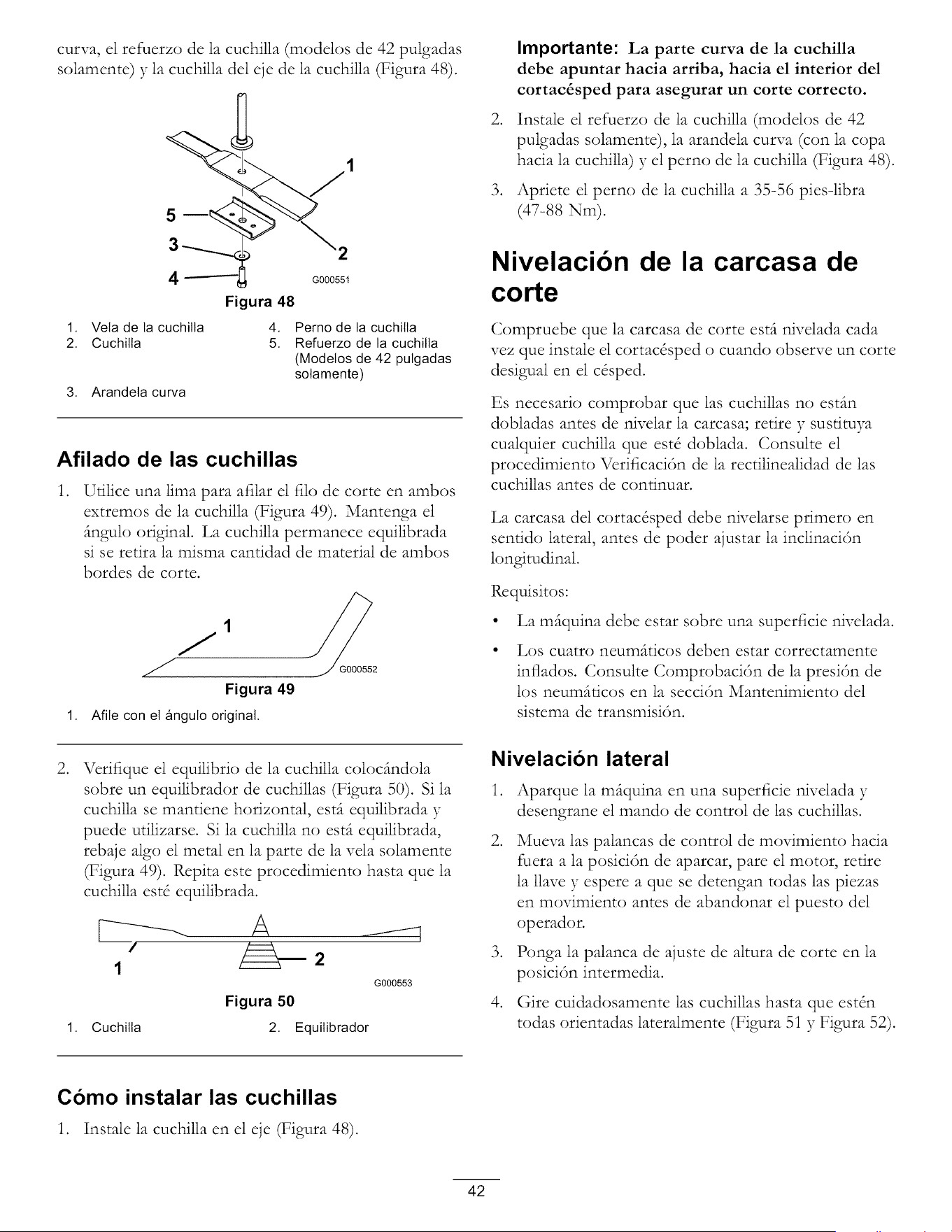
curva, el refuerzo de la cuchilla (modelos de 42 pulgadas
solamente) y la cuchilla del eje de la cuchilla (Figura 48).
5
4
1. Veta de la cuchilla
2. Cuchilla
3. Arandela curva
2
G000551
Figura 48
4. Perno de la cuchilta
5. Refuerzo de la cuchitla
(Modetos de 42 pulgadas
sotamente)
Afilado de las cuchillas
,
Utilice una lima para afilar el filo de corte en ambos
extremos de la cuchilla (Figura 49). Mantenga el
(mgulo original. La cuchilla permanece equilibrada
si se retira la misma cantidad de material de ambos
hordes de corte.
Figura 49
1. Afile con el _ngulo original.
G000552
,
°
Importante: La parte curva de la cuchilla
debe apuntar hacia arriba, hacia el interior del
cortac&sped para asegurar un corte correcto.
Instale el refuerzo de la cuchilla (modelos de 42
pulgadas solamente), la arandela curva (con la copa
hacia la cuchilla) y el perno de la cuchilla (Figura 48).
Apriete el perno de la cuchilla a 35=56 piesqibra
(47=88 Nm).
Nivelacibn de la carcasa de
corte
Compruebe que la carcasa de corte esdt nivelada cada
vez que instale el cortac&ped o cuando observe un corte
desigual en el c&ped.
Cs necesario comprobar que las cuchillas no esdm
dobladas antes de nivelar la carcasa; retire y sustituya
cualquier cuchilla que est_ doblada. Consulte el
procedimiento Vcrificaci6n de la rectilinealidad de las
cuchillas antes de conrinuar.
La carcasa del cortac&ped debe nivelarse primero en
senddo lateral, antes de poder ajustar la inclinaci6n
longitudinal.
Rcquisitos:
• La mftquina debe estar sobre una superficie nivelada.
• Los cuatro neum(tticos deben estar correctamente
inflados. Consulte Comprobaci6n de la presi6n de
los neumftticos en la secci6n Mantenimiento del
sistema de transmisi6n.
°
Vcrifique el equilibrio de la cuchilla colocdmdola
sobre un equilibrador de cuchillas (Figura 50). Si la
cuchilla se mantiene horizontal, estft equilibrada y
puede utilizarse. Si la cuchilla no esdt equilibrada,
rebaje algo el metal en la parte de la vela solamente
(Figura 49). Rcpita este procedimiento basra que la
cuchilla est_ equilibrada.
F---------- A
1
Figura 50
1. Cuchilla 2. Equilibrador
G000553
Nivelacion lateral
°
°
°
°
Aparque la m_tquina en una superficie nivelada y
desengrane el mando de control de las cuchillas.
Mueva las palancas de control de movimiento hacia
fuera a la posici6n de aparcar, pare el motor, retire
la llave y espere a que se detengan todas las piezas
en movimiento antes de abandonar el puesto del
operador.
Ponga la palanca de ajuste de altura de corte en la
posici6n intermedia.
(}ire cuidadosamente 1as cuchillas basra que est4n
todas orientadas lateralmente (Figura 5i y Figura 52).
Como instalar las cuchillas
1. Instale la cuchilla en el eje (Figura 48).
42
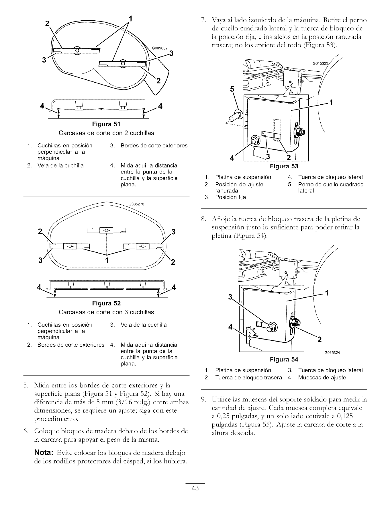
G009682
.
Vaya al lado izquierdo de la m_iquina. Retire el perno
de cuello cuadrado lateral y la tuerca de bloqueo de
la posici6n fija, e inst_ilelos en la posici6n ranurada
trasera; no los apriete del todo (Figura 53).
Figura 51
Carcasas de corte con 2 cuchillas
1. Cuchiltas en posici6n
perpendicular a la
m_quina
2. Vela de la cuchilla
3. Bordes de corte exteriores
4,
Mida aqui la distancia
entre la punta de la
cuchilta y la superficie
plana.
2 // _ _/_/3
3 2
.
5
_3
Figura 53
1. Ptetina de suspensi6n 4. Tuerca de btoqueo lateral
2. Posici6n de ajuste 5. Perno de cuelto cuadrado
ranurada lateral
3. Posici6n fija
Afloje la tuerca de bloqueo trasera de la pletina de
suspensi6n justo lo suficiente para poder retirar la
plerina (Figura 54).
.
.
Figura 52
Carcasas de corte con 3 cuchillas
1. Cuchiltas en posici6n
perpendicular a la
m_quina
2. Bordes de corte exteriores
3. Veta de la cuchilta
4,
Mida aqui la distancia
entre la punta de la
cuchilta y la superficie
plana.
Mida entre los hordes de corte exteriores y la
superficie plana (Figura 5i y Figura 52). Si hay una
difcrencia de m_s de 5 mm (3/i6 pulg.) entre ambas
dimensiones, se requiere un ajuste; siga con este
procedimiento.
Coloque bloques de madera debajo de los bordes de
la carcasa para apoyar el peso de la misma.
Nota: Evite colocar los bloques de madera debajo
de los rodilk)s protectores del c&ped, si los hubiera.
1,
2.
.
G015324
Figura 54
Pletina de suspensi6n 3. Tuerca de btoqueo lateral
Tuerca de btoqueo trasera 4. Muescas de ajuste
Utilice las muescas del soporte soldado para medir la
cantidad de ajuste. Cada muesca completa equivale
a 0,25 pulgadas, y un solo lad() equivale a 0,i25
pulgadas (Figura 55). Ajuste la carcasa de corte a la
altura deseada.
43
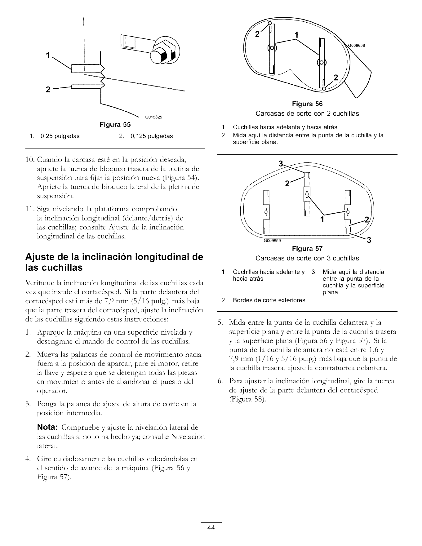
1
G015325
Figura 55
1. 0,25 pulgadas 2. 0,125 pulgadas
10. Cuando la carcasa est_ en la posici_3n deseada,
apriete la tuerca de bloqueo trasera de la pletina de
suspensi6n para fijar la posici6n nueva (Figura 54).
Apriete la tuerca de bloqueo lateral de la pletina de
suspensi6n.
11. Siga nivelando la plataforma comprobando
la inclinaci6n longitudinal (delante/detr_s) de
las cuchillas; consulte Ajuste de la inclinaci6n
longitudinal de las cuchillas.
Ajuste de la inclinacion longitudinal de
las cuchillas
Vcrifique la inclinaci6n longitudinal de las cuchillas cada
vez que instale el cortac&ped. Si la parte delantera del
cortac&ped est(t m(ts de 7,9 mm (5/16 pulg.) m(ts baja
que la parte trasera del cortac&ped, ajuste la inclinaci6n
de las cuchillas siguiendo estas instrucciones:
,
,
,
,
Aparque la mfiquina en una superficie nivelada y
desengrane el mando de control de las cuchillas.
Mueva las palancas de control de movimiento hacia
fuera a la posici6n de aparcar, pare el motor, retire
la llave y espere a que se detengan todas las piezas
en movimiento antes de abandonar el puesto del
operador.
Ponga la palanca de ajuste de altura de corte en la
posici6n intermedia.
Nota: Compruebe y ajuste la nivelaci6n lateral de
las cuchillas si no lo ha hecho ya; consulte Nivelaci6n
lateral.
(}ire cuidadosamente las cuchillas coloc(mdolas en
el senrido de avance de la m(tquina (Figura 56 y
Figura 57).
Figura 56
Carcasas de corte con 2 cuchillas
.
.
1. Cuchillas hacia adetante y hacia atr_s
2. Mida aquila distancia entre la punta de la cuchilla y la
superficie plana.
G009659 3
Figura 57
Carcasas de corte con 3 cuchillas
1. Cuchiltas hacia adetante y 3. Mida aquila distancia
hacia atr_s entre la punta de la
cuchilla y la superficie
ptana.
2. Bordes de corte exteriores
Mida entre la punta de la cuchilla delantera y la
superficie plana y entre la punta de la cuchilla trasera
y la superficie plana (Figura 56 y Figura 57). Si la
punta de la cuchilla delantera no est(t entre 1,6 y
7,9 mm (i/16 y 5/i6 pulg.) m(ts baja que la punta de
la cuchilla trasera, ajuste la contratuerca delantera.
Para ajustar la inclinaci_3n longitudinal, gire la tuerca
de ajuste de la parte delantera del cortac&ped
(Figura 58).
44
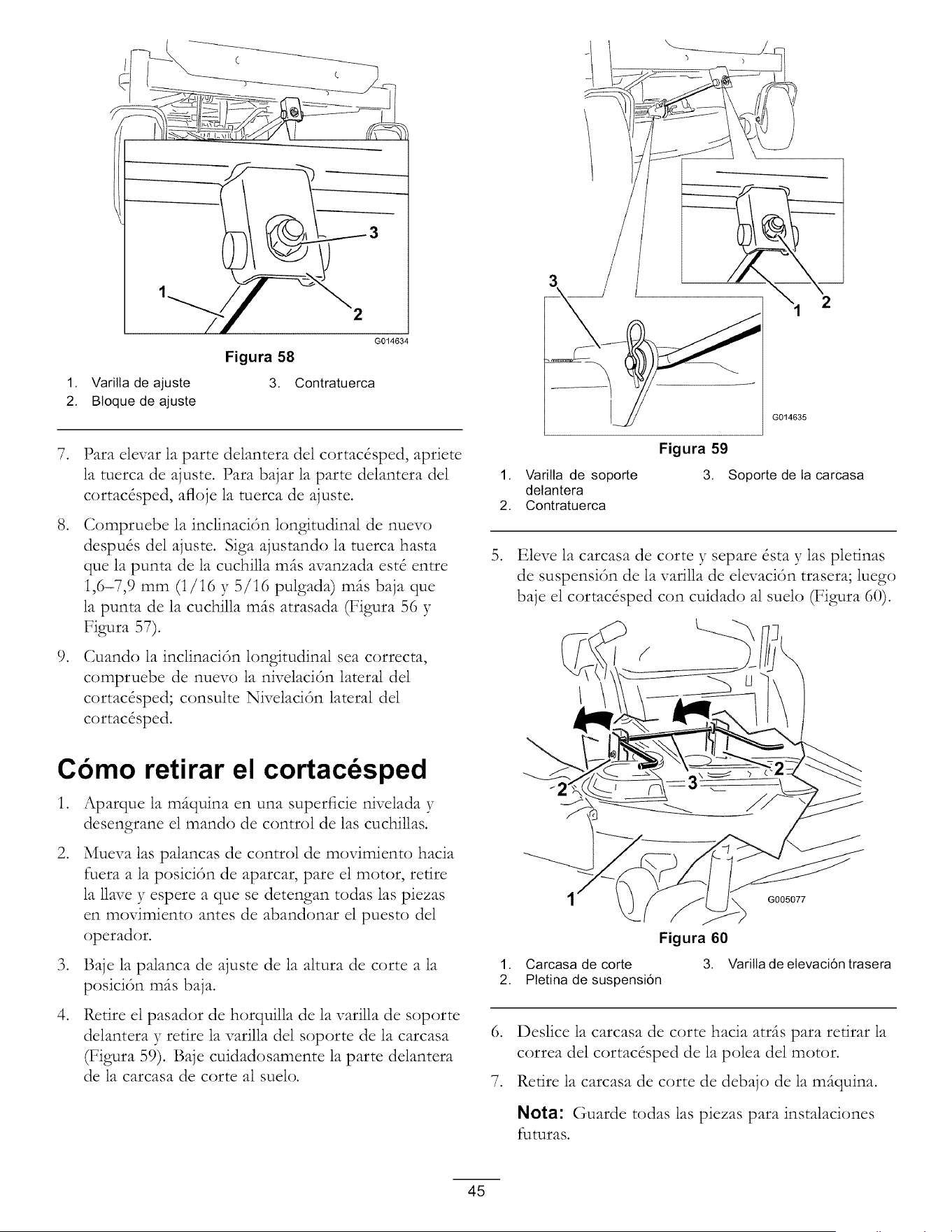
1. Varilla de ajuste
2. Bloque de ajuste
2
G014634
Figura 58
3. Contratuerca
°
°
.
Para elevar la parte delantera del cortac&ped, apriete
la tuerca de ajuste. Para bajar la parte delantera del
cortac&ped, afloje la tuerca de ajuste.
Compruebe la inclinaci6n longitudinal de nuevo
despu& del ajuste. Siga ajustando la tuerca basra
que la punta de la cuchilla m(ts avanzada est_ entre
1,6-7,9 mm (i/16 y 5/16 pulgada) m_ts baja que
la punta de la cuchilla m(ts atrasada (Figura 56 y
Figura 57).
Cuando la inclinaci6n longitudinal sea correcta,
compruebe de nuevo la nivelaci6n lateral del
cortac&ped; consulte Nivelaci6n lateral del
cortac&ped.
Cbmo retirar el cortac sped
1. Aparque la m_tquina en una superficie nivelada y
desengrane el mando de control de las cuchillas.
.
Mueva las palancas de control de movimiento hacia
fuera a la posici6n de aparcar, pare el motor, retire
la llave y espere a que se detengan todas las piezas
en movimiento antes de abandonar el puesto del
operador.
3. Baje la palanca de ajuste de la altura de corte a la
posici6n m_ts baja.
°
Retire el pasador de horquilla de la varilla de soporte
delantera y retire la varilla del soporte de la carcasa
(Figura 59). Baje cuidadosamente la parte delantera
de la carcasa de corte al suelo.
.
3
1. Varilla de soporte
detantera
2. Contratuerca
1,
2.
G014635
Figura 59
3. Soporte de la carcasa
Eleve la carcasa de corte y separe &tay las pletinas
de suspensi6n de la varilla de elevaci6n trasera; luego
baje el cortac&ped con cuidado al suelo (Figura 60).
1 G005077
Figura 60
Carcasa de corte 3. Vadlla de elevaci6n trasera
Pletina de suspensi6n
6. Deslice la carcasa de corte hacia atr(ts para retirar la
correa del cortac&ped de la polea del motor.
7. Retire la carcasa de corte de debajo de la m(tquina.
Nota: Guarde todas las piezas para instalaciones
futuras.
45
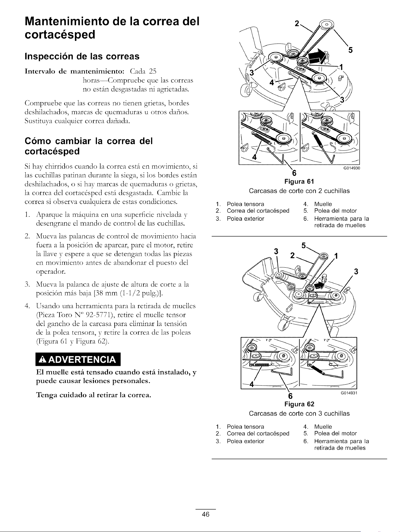
Mantenimiento de la correa del
cortac sped
Inspeccion de las correas
Intervalo de mantenimiento: Cada 25
horas--Compruebe que las correas
no estfin desgastadas ni agrietadas.
Compruebe que las correas no tienen grietas, bordes
deshilachados, marcas de quemaduras u otros dafios.
Sustituya cualquier correa dafiada.
Como cambiar la correa del
cortacesped
Si hay chirridos cuando la correa est(t en movimiento, si
las cuchillas patinan durante la siega, si los bordes esdm
deshilachados, o si ha}* marcas de quemaduras o grietas,
la correa del cortac&ped est(t desgastada. Cambie la
correa si observa cualquiera de estas condiciones.
.
.
.
.
Aparque la m_tquina en una superficie nivelada y
desengrane el mando de control de las cuchillas.
Mueva las palancas de control de movimiento hacia
fuera a la posici6n de aparcar, pare el motor, retire
la llave y espere a que se detengan todas las piezas
en movimiento antes de abandonar el puesto del
operador.
Mueva la palanca de ajuste de altura de corte a la
posici6n m_ts baja [38 mm (1-1/2 pulg.)].
Usando una herramienta para la retirada de muelles
_ieza Toro N ° 92-577i), retire el muelle tensor
del gancho de la carcasa para eliminar la tensi6n
de la polea tensora, y retire la correa de las poleas
(Figura 61 y Figura 62).
E1 muelle estfi tensado cuando estfi instalado, y
puede causar lesiones personales.
Tenga cuidado al retirar la correa.
5
7
\
6
)
G014930
Figura 61
Carcasas de corte con 2 cuchillas
1. Potea tensora 4. Muetle
2. Correa det cortac6sped 5. Potea det motor
3. Potea exterior 6. Herramienta para la
retirada de muelles
3
3
I ///i_"-> ""
G014931
Figura 62
Carcasas de corte con 3 cuchillas
1. Potea tensora 4. Muetle
2. Correa det cortac6sped 5. Potea det motor
3. Potea exterior 6. Herramienta para la
retirada de muelles
46
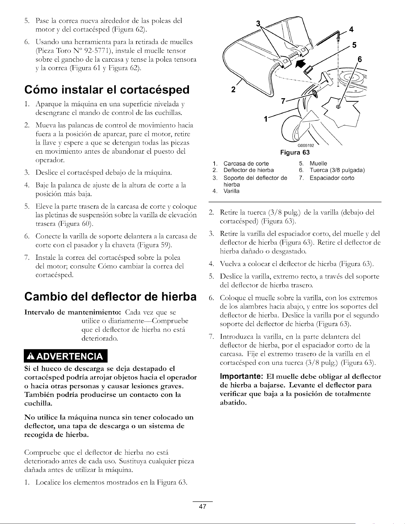
.
.
Pase la correa nueva alrededor de las poleas del
motor y del cortac&ped (Figura 62).
Usando una herramienta para la retirada de muelles
_ieza Toro N ° 92-5771), instale el muelle tensor
sobre el gancho de la carcasa y tense la polea tensora
y la correa (Figura 61 y Figura 62).
Cbmo instalar el cortacdsped
1. Aparque la mfiquina en una superficie nivelada y
desengrane el mando de control de las cuchillas.
,
Mueva las palancas de control de movimiento hacia
fuera a la posici6n de aparcar, pare el motor, retire
la llave y espere a que se detengan todas las piezas
en movimiento antes de abandonar el puesto del
operador.
3. Deslice el cortac&ped debajo de la miquina.
4. Baje la palanca de ajuste de la altura de corte a la
posici6n mils baja.
5. Eleve la parte trasera de la carcasa de corte y coloque
las plefinas de suspensi6n sobre la varilla de elevaci6n
trasera (Figura 60).
6. Conecte la varilla de soporte delantera a la carcasa de
corte con el pasador y la chaveta (Figura 59).
7. Instale la correa del cortac&ped sobre la polea
del motor; consulte C6mo cambiar la correa del
cortac&ped.
Cambio del deflector de hierba
Intervalo de mantenimiento: Cada vez que se
utilice o diariamente--Compruebe
que el deflector de hierba no esti
deteriorado.
Si el hueco de descarga se deja destapado el
cortac&sped podria arrojar objetos hacia el operador
o hacia otras personas y causar lesiones graves.
Tambi_n podria producirse un contacto con la
cuchilla.
No utilice la mfiquina nunca sin tener colocado un
deflector, una tapa de descarga o un sistema de
recogida de hierba.
Compruebe que el deflector de hierba no esti
deteriorado antes de cada uso. Sustituya cualquier pieza
dafiada antes de utilizar la miquina.
1. Localice los elementos mostrados en la Figura 63.
,
,
,
5.
.
°
4
6
2
G005192
Figura 63
1. Carcasa de corte 5. Muetle
2. Deflector de hierba 6. Tuerca (3/8 pulgada)
3. Soporte del deflector de 7. Espaciador corto
hierba
4. Varilla
Retire la tuerca (3/8 pulg.) de la varilla (debajo del
cortac&ped) (Figura 63).
Retire la varilla del espaciador corto, del muelle y del
deflector de hierba (Figura 63). Retire el deflector de
hierba dahado o desgastado.
Vuelva a colocar el deflector de hierba (Figura 63).
Deslice la varilla, extremo recto, a tray& de1 soporte
del deflector de hierba trasero.
Coloque el muelle sobre la varilla, con los extremos
de los alambres hacia abajo, y entre los soportes del
deflector de hierba. Deslice la varilla pot el segundo
soporte del deflector de hierba (Figura 63).
Introduzca la varilla, en la parte delantera del
deflector de hierba, pot el espaciador corto de la
carcasa. Fije el extremo trasero de la varilla en el
cortac&ped con una tuerca (3/8 pulg.) (Figura 63).
Importante: E1 muelle debe obligar al deflector
de hierba a bajarse. Levante el deflector para
verificar que baja a la posici6n de totalmente
abatido.
47
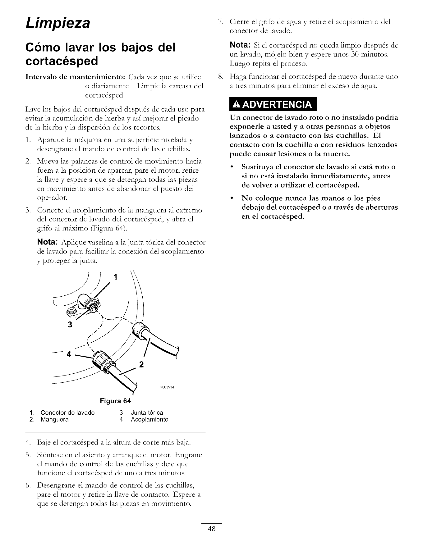
Limpieza
Cbmo lavar los bajos del
cortacdsped
Intervalo de mantenimiento: Cada vez que se utilice
() diariamente--Limpie la carcasa del
cortac&ped.
Lave los bajos del cortac&ped despu& de cada uso para
evitar la acumulaci6n de hierba y asf mejorar el picado
de la hierba y la dispersi6n de los recortes.
1. Aparque la m_tquina en una superficie nivelada y
desengrane el mando de control de las cuchillas.
2. Mueva las palancas de control de movimiento hacia
fuera a la posici6n de aparcar, pare el motor, retire
la llave y espere a que se detengan todas las piezas
en movimiento antes de abandonar el puesto del
operador.
3. Conecte el acoplamiento de la manguera al extremo
del conector de lavado del cortac&ped, y abra el
grifo al m(tximo (Figura 64).
Nota: Aplique vaselina a la junta t6rica del conector
de lavado para facilitar la conexi6n del acoplamiento
y proteger la junta.
3
°
.
Cierre el grifo de agua y retire el acoplamiento del
conector de lavado.
Nota: Si el cortac&ped no queda limpio despu& de
un lavado, m6jelo bien y espere unos 30 minutos.
Luego repita el proceso.
Haga funcionar el cortac&ped de nuevo durante uno
atres minutos para eliminar el exceso de agua.
Un conector de lavado roto o no instalado podria
exponerle a usted y a otras personas a objetos
lanzados o a contacto con las cuchillas. E1
contacto con la cuchilla o con residuos lanzados
puede causar lesiones o la muerte.
• Sustituya el conector de lavado si estfi roto o
si no estfi instalado inmediatamente, antes
de volver a utilizar el cortac&sped.
• No coloque nunca las manos o los pies
debajo del cortac&sped o a trav&s de aberturas
en el cortac_sped.
G003934
Figura 64
1. Conector de lavado 3. Junta t6rica
2. Manguera 4. Acoptamiento
4. Baje el cortac&ped a la altura de corte m(ts baja.
5. Si_ntese en el asiento y arranque el motor. Engrane
el mando de control de las cuchillas y deje que
funcione el cortac&ped de uno atres minutos.
6. Desengrane el mando de control de las cuchillas,
pare el motor y retire la llave de contacto. Espere a
que se detengan todas las piezas en movimiento.
48

Almacenamiento
Limpieza y almacenamiento
1. Desengrane el mando de control de las cuchillas,
mueva los controles de movimiento hacia fuera a la
posici6n de aparcar, pare el motor y retire la llave.
2. Retire los recortes de hierba, la suciedad y la
mugre de las piezas externas de toda la mfiquina,
especialmente el motor. Limpie la suciedad y la broza
de la parte exterior del alojamiento de las aletas de la
culata de cilindros del motor y del soplador.
.
Importante: La mfiquina puede lavarse con un
detergente suave y agua. No lave la mfiquina
a presi6n. Evite el uso excesivo de agua,
especialmente cerca del panel de control, debajo
del asiento, y alrededor del motor, de las bombas
hidrfiulicas y de los motores el&ctricos.
Revise el limpiador de aire; consulte Mantenimiento
del limpiador de aire en la secci6n Mantenimiento
del motor.
4. Cngrase y lubrique la mfiquina; consulte la secci6n
Lubricaci6n.
5. Cambie el aceite del critter y el filtro; consulte
Mantenimiento del aceite del motor, en la secci6n
Mantenimiento del Motor.
6. Compruebe la presi6n de los neumfiticos; consulte
Comprobaci6n de la presi6n de los neumfiticos en la
secci6n Mantenimiento del sistema de transmisi6n.
7. (;argue la bater_a; consulte Mantenimiento de la
bater_a en la secci6n Mantenimiento del sistema
el&trico.
8. Compruebe la condici6n de las cuchillas; consulte
Mantenimiento de las cuchillas en la secci6n de
Mantenimiento del cortac&ped.
9. Prepare la mfiquina para su almacenamiento cuando
no la vaya a utilizar durante mils de 30 dias. Prepare
la mfiquina para el almacenamiento de la manera
siguiente:
10. Agregue un estabilizador/acondicionador a base
de petr61eo al combustible del dep6sito. Siga
las instrucciones de mezcla del fabricante del
estabilizador. No use un estabilizador a base de
alcohol (etanol o metanol).
Nota: Un estabilizador/acondicionador de
combustible es mils eficaz cuando se mezcla con
gasolina fresca y se utiliza en todo momento.
Haga funcionar el motor para distribuir el
combustible con acondicionador pot todo el sistema
de combustible (5 minutos).
11.
12.
13.
14.
15.
16.
17.
Pare el motor, deje que se enfr_e, y drene el dep6sito
de combustible; consulte Drenaje del dep6sito
de combustible, en la secci6n Mantenimiento del
sistema de combustible.
Vuelva a arrancar el motor y hfigalo funcionar hasta
que se pare.
Accione el estfirter. Arranque el motor y d_jelo
funcionar hasta que no xmelva a arrancar.
Deseche el combustible adecuadamente. Recicle
observando la normativa local.
Importante: No guarde la gasolina con
estabilizador/acondicionador durante mils de
30 dias.
Retire la(s) buj_a(s) y verifique su condici6n;
consulte Mantenimiento de la buj_a, en la secci6n
Mantenimiento del Motor. Con la(s) buj_a(s)
retirada(s) del motor, vierta dos cucharadas soperas
de aceite de motor en el agujero de la bufia. Utilice
el motor de arranque para hacer girar el motor y
distribuir el aceite dentro del cilindro. Instale la(s)
buj_a(s). No instale los cables en la(s) buj_a(s).
Limpie cualquier suciedad y recortes de encima del
cortac&ped.
Rasque cualquier acumulaci6n importante de hierba
y suciedad de los bajos del cortacdsped, luego lfivelo
con una manguera de jardin.
Compruebe la condici6n de las correas de
transmisi6n y del cortac&ped.
Revise y apriete todos los pernos, tuercas y tornillos.
Repare o sustituya cualquier pieza desgastada o
dafiada.
Pinte las superficies que estSn arafiadas o donde
est8 visible el metal. Puede adquirir la pintura en su
Servicio T&nico Autorizado.
Guarde la mfiquina en un garaje o almacdn seco y
limpio. Retire la llave de contacto y gu_trdela en un
lugar seguro que le sea fdcil de recordar. Cubra la
mfiquina para protegerla y para conservarla limpia.
49

Solucion de problemas
Problema Posible causa
El motor se sobrecalienta.
El motor de arranque no gira.
El motor no arranca, arranca con dificultad,
o no sigue funcionando.
El motor pierde potencia.
1,
2.
3.
4,
5.
La carga del motor es excesiva.
El nivet de aceite det c_rter est_ bajo.
Las atetas de refrigeraci6n y los
conductos de aire situados debajo del
atojamiento det soplador del motor
est_n obstruidos.
El limpiador de aire est_ sucio.
Hay suciedad, agua o combustible
viejo en el sistema de combustible.
1. El mando de control de las cuchiltas
est_ engranado.
2. Las patancas de control de movimiento
no est_n en la posici6n de aparcar.
3. La bateria est_ descargada.
4. Las conexiones et6ctricas est_n
corroidas o suettas.
5. Un fusible esta fundido.
6. Un rel6 o interruptor est_ dadado.
1,
2.
3.
4.
5.
6,
7.
El dep6sito de combustible est_ vacio.
El est_rter no est_ cerrado.
El limpiador de aire est_ sucio.
El/los cable(s) de la(s) bujia(s) est,(n)
suetto(s) o desconectado(s).
La bujia est_ picada, sucia o la
distancia entre los electrodos es
incorrecta.
El filtro de combustible est_ sucio.
Hay suciedad, agua o combustible
viejo en et sistema de combustible.
8. Hay combustible incorrecto en el
dep6sito de combustible.
9. El nivel de aceite del c_rter est_ bajo.
1. La carga del motor es excesiva.
2. El limpiador de aire est_ sucio.
3. El nivet de aceite det c_rter est_ bajo.
4. Las atetas de refrigeraci6n y los
conductos de aire situados debajo del
atojamiento det soplador del motor
est_n obstruidos.
5. La bujia est_ picada, sucia o la
distancia entre los electrodos es
incorrecta.
6. El orificio de ventilaci6n det dep6sito
de combustible est_ obstruido.
7. El filtro de combustible est_ sucio.
8. Hay suciedad, agua o combustible
viejo en et sistema de combustible.
9. Hay combustible incorrecto en el
dep6sito de combustible.
1,
2.
3.
Accion correctora
Reduzca la vetocidad sobre el terreno.
Arhada aceite at c_rter.
Elimine la obstrucci6n de las atetas
de refrigeraci6n y de los conductos de
aire.
4. Limpie o cambie el filtro del limpiador
de aire.
5. P6ngase en contacto con et Servicio
T6cnico Autorizado.
1. Mueva et mando de control de las
cuchillas a Desengranado.
2. Mueva las palancas de control de
movimiento hacia afuera a la posici6n
de aparcar.
3. Cargue la bateria.
4. Verifique que hay buen contacto en las
conexiones et6ctricas.
5. Cambie et fusible.
6. P6ngase en contacto con et Servicio
T6cnico Autorizado.
1. Llene et dep6sito de combustible.
2. Mueva la patanca del est_rter a
Cerrado.
3. Limpie o cambie el filtro del limpiador
de aire.
4. Instale el cable en la bujia.
5. Instate una bujia nueva, con los
electrodos a la distancia correcta.
6. Cambie et filtro de combustible.
7. P6ngase en contacto con et Servicio
T6cnico Autorizado.
8. Drene et dep6sito y rellene con
combustible det tipo correcto.
9. A5ada aceite al c_rter.
1. Reduzca la velocidad sobre el terreno.
2. Limpie et filtro del limpiador de aire.
3. Adada aceite at c_rter.
4. Elimine la obstrucci6n de las atetas
de refrigeraci6n y de los conductos de
aire.
5,
Instate una bujia nueva, con los
electrodos a la distancia correcta.
6. P6ngase en contacto con et Servicio
T6cnico Autorizado.
7. Cambie et filtro de combustible.
8. P6ngase en contacto con et Servicio
T6cnico Autorizado.
9. Drene et dep6sito y rellene con
combustible del tipo correcto.
50
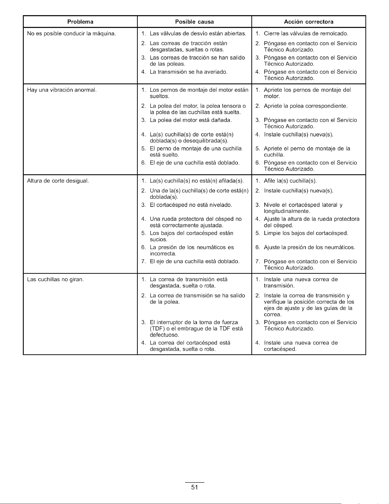
Problema
No es posibte conducir la m_quina.
Hay una vibraci6n anormal.
Altura de corte desigual.
Las cuchillas no giran.
1.
2. Las correas de tracci6n est_n
desgastadas, suettas o rotas.
3. Las correas de tracci6n se han satido
de las poteas.
4. La transmisi6n se ha averiado.
1.
2.
3.
4.
5.
6.
Posible causa Accion correctora
Las v_lvulas de desvio est_n abiertas. Cierre las v_tvulas de remotcado.
1.
2.
3.
4.
5.
6.
7.
Los pernos de montaje del motor est_n
suettos.
La potea det motor, la polea tensora o
la potea de las cuchiltas est_ suetta.
La polea det motor est_ da5ada.
La(s) cuchilta(s) de corte est.(n)
dobtada(s) o desequilibrada(s).
El pemo de montaje de una cuchilta
est_ suetto.
El eje de una cuchilla est_ dobtado.
La(s) cuchitla(s) no est.(n) afilada(s).
Una de la(s) cuchilla(s) de corte est.(n)
dobtada(s).
El cortac6sped no est_ nivelado.
Una rueda protectora det c6sped no
est_ correctamente ajustada.
Los bajos del cortac6sped est_n
sucios.
La presi6n de los neum_ticos es
incorrecta.
El eje de una cuchilla est_ dobtado.
1. La correa de transmisi6n est_
desgastada, suetta o rota.
2. La correa de transmisi6n se ha salido
de la potea.
3. El interruptor de ta toma de fuerza
(TDF) o et embrague de la TDF est_
defectuoso.
4. La correa det cortac6sped est_
desgastada, suetta o rota.
1.
2.
3.
4.
P6ngase en contacto con et Servicio
T6cnico Autorizado.
P6ngase en contacto con et Servicio
T6cnico Autorizado.
P6ngase en contacto con et Servicio
T6cnico Autorizado.
1. Apriete los pernos de montaje del
motor.
2. Apriete la potea correspondiente.
3. P6ngase en contacto con et Servicio
T6cnico Autorizado.
4. Instale cuchilta(s) nueva(s).
5. Apriete et perno de montaje de la
cuchilta.
6. P6ngase en contacto con et Servicio
T6cnico Autorizado.
1.
2.
3.
4.
5.
6.
7.
1.
2.
3.
4.
Afile la(s) cuchilla(s).
Instale cuchilta(s) nueva(s).
Nivete et cortac6sped lateral y
Iongitudinatmente.
Ajuste la altura de la rueda protectora
det c6sped.
Limpie los bajos del cortac6sped.
Ajuste la presi6n de los neum_ticos.
P6ngase en contacto con et Servicio
T6cnico Autorizado.
Instate una nueva correa de
transmisi6n.
Instate ta correa de transmisi6n y
verifique la posici6n correcta de los
ejes de ajuste y de las guias de la
correa.
P6ngase en contacto con et Servicio
T6cnico Autorizado.
Instate una nueva correa de
cortac6sped.
51
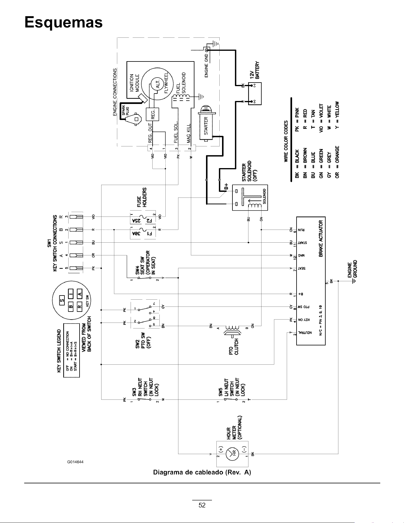
0
m"
LQ
B
3
Q..
(I)
(3
0"
.<
KEY SWITCH LEGEND F I'-_'-I _
oFF=NOCONN_C_O.1/ r--._r_'_ \
ON = B+R+I+A I I _ I I I I
VIEWED FROM __/
BACK OF SWITCH
SWl
KEY SWITCH CONNECTIONS
I A S B R
5 4 1 2 3
)
H°U_R
(o_o_)
P
RH NEUT
SWITCH
(IN NEUT
LOCK)
I
SW5
SW2
PTOsw
LH NEUT
SWITCH
(IN NEUT
2 LOCK)
(OFF)
A
B
÷
21
i(
41 BI
SEAT SW
(OPERATOR
IN SEAT)
2
__p, ENO,NECONNECT,ONS
' J_l ,GN,T,ON
FUSE U,,L.I/PI ]",. MODULE
HOLDERS r.. _ _
2 _O2 VlO 4 REG. OUT
l_
PK 3 FUEL SOL. ' "'_FUEL
, I " II_soLENOID
w [_ MAG KILL iii
oiil , ,_O,_NO,D
[NOID J
WIRE COLOR CODES
N/C = PIN 3, 9, lg
11 71 121 11 sl
BRAKE ACTUATOR
BK
__ENGINE
-": GROUND
BK = BLACK PK = PINK
BN = BROWN R = RED
BU = BLUE T = TAN
GN = GREEN VIO = VIOLET
GY = GREY W = WHITE
OR = ORANGE Y = YELLOW
ITI
U)
.Q
€1)
3
U_

Notas:
53

Notas:
54

Notas:
55
La Garantia Toro de cobertura total
cortac6spedes TITAN (ver periodos de garantia m_s adetante)
Cortac6spe-
des Time-
Cutter
Y
Garantia
limitada
sobre
Condiciones y productos cubiertos
The Toro Company y su afiliado, Toro Warranty Company, bajo un acuerdo entre si,
prometen conjuntamente at comprador original reparar los Productos Toro citados a
continuaci6n si tienen defectos de mater!ales o mano de obra.
Los siguientes plazos son aplicabtes desde la fecha de la compra por et propietario
original:
Productos
Todos los cortac6spedes
• Motor
• Bateria
•Correas y neum_ticos
Cortac6spedes y accesorios TimeCutter
Z
Cortac6spedes y accesorios TITAN
• Bastidor
Cortac6spedes y accesorios TITAN MX
• Bastidor
Periodo de garantia
Consulte la garantia det fabricante det
motor 1
1-90 dias piezas y mane de obra
91-365 dias s61o piezas
90 dias
30 dias uso comerciat
3 afios en uso residenciat 2
3 afios o 240 horas 3
Vida det producto (Qnicamente et
propietario original) 4
3 afios o 400 horas 3
Vida det producto (Qnicamente et
propietario original) 4
IAIgunos motores utilizados en los productos Toro estgn garantizados por el fabricante det rnotoc
2"Uso residenciaF significa et uso det producto en ta rnisrna parceta en que se encuentra su
vivienda. El uso en rngs de un lugar se considera corno uso cornercial y ser9 aplicable la garantia
de uso cornerciaL
3El que ocurra primero.
4Garantia de por vida del bastidor Si el bastidor principal, que consta de las piezas que
estgn soldadas entre si para forrnar la estructura de tractor a la que estgn conectados otros
cornponentes tales corno et motor, se agrieta 0 se rornpe durante et uso normal, ser9 reparado 0
sustituido, a discreci6n de Toro, bajo la garantia sin coste alguno en concepto de piezas 0 rnano
de obra. Quedan excluidos los fatlos del bastidor causados por rnal uso 0 abuso y los fallos 0 las
reparaciones necesarias a causa de 6xido 0 corrosi6n.
Esta garantia inctuye et coste de piezas y mano de obra, pero usted debe pagar
los costes de transporte.
La garantia puede ser rechazada si et contador de horas es desconectado o
modificado, o muestra sefiates de manipulaci6n indebida.
Responsabilidades del propietario
Usted debe mantener su Producto Toro siguiendo los procedimientos de
mantenimiento descritos en et Manual del operador. Dicho mantenimiento rutinario,
sea reatizado por un distribuidor o por usted mismo, es por cuenta de usted.
Instrucciones para obtener asistencia bajo la garantia
Si usted cree que su producto Toro tiene un defecto de mater!ales o de mane de
obra, siga este procedimiento:
P6ngase en contacto con cualquier Distribuidor Autorizado Toro para concertar
et mantenimiento en sus instataciones. Para Iocalizar un distribuidor cerca de
usted, consulte las Paginas Amarillas tetef6nicas (mire en "cortac6spedes")
o visite nuestro sitio web en www.Toro.com. Tambi6n puede llamar a los
nt_meros que aparecen en et apartado 3 para usar et sistema de Iocatizaci6n
de Distribuidores Toro las 24 horas at dia.
Lleve et producto y su prueba de compra (recibo o factura de venta) at
Distribuidor. El distribuidor diagnosticar_ et probtema y determinar_ si est_
cubierto por la garantia.
Si per atguna raz6n usted no est_ satisfecho con et anatisis det Distribuidor o
con ta asistencia recibida, p6ngase en contacto con nosotros en la direcci6n
siguiente:
Customer Care Department, RLC Division
Toro Warranty Company
8111 Lyndate Avenue South
Bloomington, MN 55420-1196
Tet6fono gratuito: 866-216-6029 (ctientes de EE.UU.)
Tet6fono gratuito: 866-216-6030 (clientes de Canada)
Elementos y condiciones no cubiertos
No hay otra garantia expresa salvo la cobertura especial de sistemas de emisi6n y la
garantia sobre motores en atgunos productos. Esta garantia expresa no cubre:
Et coste de mantenimiento regular, servicio o piezas, come por ejemplo
filtros, combustible, lubricantes, cambios de aceite, bujias, filtros de aire,
afilado de cuchillas/cuchillas desgastadas en cortac6spedes, ajustes de
cabtes/acoplamientos o ajustes de frenos y embragues
• Los componentes que fallan debido al uso y desgaste normates no est_n
cubiertos por esta garantia.
• Cuatquier producto o pieza que haya sido modificado o real utilizado o que
haya necesitado ser sustituido o reparado debido a accidente o fatta de
mantenimiento adecuado
Reparaciones debidas a cuidados incorrectos de la bateria, irregularidades en
et suministro et6ctrico, et no utilizar combustible fresco (comprado hace menos
de un rues) o no preparar adecuadamente la unidad antes de cuatquier periodo
de no utilizaci6n superior a un rues.
Costes de recogida y entrega
Mat uso, negligencia o accidentes
Reparaciones o intentos de reparaci6n por parte de personas no pertenecientes
a un Distribuidor Autorizado Toro
Condiciones generales
Todas las reparaciones cubiertas por estas garantias deben ser reatizadas por un
Servicio T6cnico Toro Autorizado usando piezas de repuesto aprobados por Toro.
Ni The Toro Company ni Toro Warranty Company son responsables de da_os
directos, indirectos o consecuentes en conexibn con el uso de los productos
Toro cubiertos por esta garantia, incluyendo cualquier coste o gasto por la
provisibn de equipos de sustitucibn o servicio durante periodos razonables
de mal funcionamiento o no utilizacibn hasta la terminacibn de reparaciones
bajo esta garantia.
Toda garantia implicita de mercantibilidad (que el producto es adecuado para el
uso normal) y adecuacibn a un uso determinado (que el producto es adecuado
para un propbsito determinado) se limitan a la duracibn de la garantia expresa
Algunos estados no permiten exclusiones de da_os incidentales o
consecuentes, ni limitaciones sobre la duracibn de una garantia implicita, de
manera que las exclusiones y limitaciones arriba citadas pueden no serle
aplicables a usted.
Esta garantia le otorga a usted derechos legates especificos; es posibte que usted
tenga otros derechos que varian de un estado a otro.
Paises fuera de Estados Unidos o Canad&
Los clientes que compraron productos Toro exportados de los Estados Unidos o Canad_ deben ponerse en contacto con su Distribuidor (Concesionario) Toro para obtener
p61izas de garantia para su pais, provincia o estado. Si por cuatquier raz6n usted no est_ satisfecho con et servicio ofrecido por su distribuidor, o si tiene dificultad
en obtener informaci6n sobre la garantia, p6ngase en contacto con et importador Toro. Si fatlan todos los demos recursos, puede ponerse en contacto con nosotros
en Toro Warranty Company.
374-0258 Rev B