IB-205070
Owner's Manual
I CRRFTSMRN1
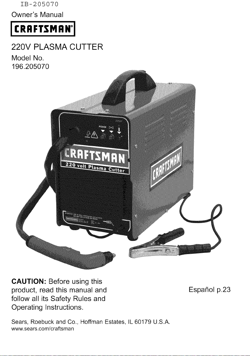
220V PLASMA CUTTER
Model No.
196.205070
CAUTION: Before using this
product, read this manual and
follow all its Safety Rules and
Operating Instructions.
Sears, Roebuck and Co., Hoffman Estates, IL 60179 U.S.A.
www.sears.com/craftsman
Espa_ol p.23
Craftsman Limited Warranty .............. 2
Introduction ........................................ 2
Safety Summary .................................. 3
Safety Information .............................. 3
Shock Hazards .................................. 4
Flash Hazards .................................... 4
Fire Hazards ...................................... 5
Plasma Arc Hazards .......................... 6
Fume Hazards .................................... 6
Additional Safety Information ............ 7
Plasma Cutter Specifications ............ 8
Description ........................................ 8
Operating Characteristics .................. 8
Duty Cycle ........................................ 8
Internal Thermal Protection .............. 8
Pneumatic Protection ...................... 8
Electric Shock Protection ................ 8
Know Your Plasma Cutter .................. 9
Plasma Cutter Installation .................. 10
Site Selection .................................... 10
Power Source Connection ................ 10
Power Requirements ........................ 10
Connect to Power Source ................ 10
Extension Cords .............................. 10
Assembling the Plasma Cutter .......... 10
Unpacking the Plasma Cutter .......... 10
Packing List...................................... 10
Assemble the Face Shield .............. 11
Installing the Handle ........................ 11
Operation ............................................ 11
Connecting the Air Supply .................. 11
Connecting the Ground Clamp to the
Workpiece .......................................... 12
Powering Up the Unit ........................ 12
Principles of Plasma Cutting .............. 12
Learning to Plasma Cut ...................... 12
Holding the Torch ............................ 13
Position the Torch to the Workpiece 13
Cutting ................................................ 13
Piercing .............................................. 14
Recommended Cutting Speeds ........ 14
Maintenance ........................................ 15
Draining Condensation ...................... 15
Replacing the Nozzle ........................ 15
Replacing the Electrode .................... 16
Replacing the Swirl Ring .................... 16
Replacing the Nozzle Cap .................. 16
Troubleshooting .................................. 16
Wiring Diagram .................................... 18
Parts List .............................................. 19
Limited Three-Year Warranty on Craftsman Plasma Cutter
For three years from the date of purchase, if any part of this plasma cutter, except for the gun
or cables, fails due to a defect in material or workmanship, return it to your nearest Sears Parts
& Repair Center, and it will be repaired free of charge. Sears will repair the gun or cables free
of charge for only one year from the date of purchase. This warranty does not cover expend-
able parts such as electrodes, nozzles or nozzle caps, which are consumed during normal
plasma cutter operation. This warranty applies only while this product is used in the United
States. This warranty gives you specific legal rights, and you may also have other rights which
vary from state to state.
Sears, Roebuck and Co., D/817WA, Hoffman Estates, IL 60179
This owner's manual provides all of the specific information you need to safely and effectively use
your Plasma Cutter. Itcontains instructions on safety, set-up, installation and actual Plasma Cutter
operation.
Everycraftsmanrespectsthetoolswith
whichtheywork.Theyknowthatthetools
representyearsofconstantlyimproved
designsanddevelopments,Thetrue
craftsmanalsoknowsthattoolsare
dangerousifmisusedorabused,
Readingthisoperator'smanualbeforeusing
theplasmacutterwiltenableyoutodoabet-
ter,saferjob.Learntheplasmacutter's
applicationsandlimitationsasweltasthe
specificpotentialhazardspeculiartoplasma
cutting.
IMPORTANT SAFETY
INFORMATION
The following safety information is provided
as guidelines to help you operate your new
plasma cutter under the safest possible con-
ditions. Any equipment that uses electrical
power can be potentially dangerous to use
when safety or safe handling instructions are
not known or not followed. The following
safety information is provided to give the
user the information necessary for safe use
and operation.
A procedure step preceded by a
WARNING is an indication that the next step
contains a procedure that might be injurious
to a person if proper safety precautions are
not heeded,
A procedure step preceded by a CAUTION
is an indication that the next step contains a
procedure that might damage the equipment
being used,
A NOTE may be used before or after a
procedure step to highlight or explain
something in that step.
READ ALL SAFETY INSTRUCTIONS
CAREFULLY before attempting to install,
operate, or service this plasma cutter. Failure
to comply with these instructions could result
in personal injury and/or property damage.
RETAIN THESE INSTRUCTIONS FOR
FUTURE REFERENCE.
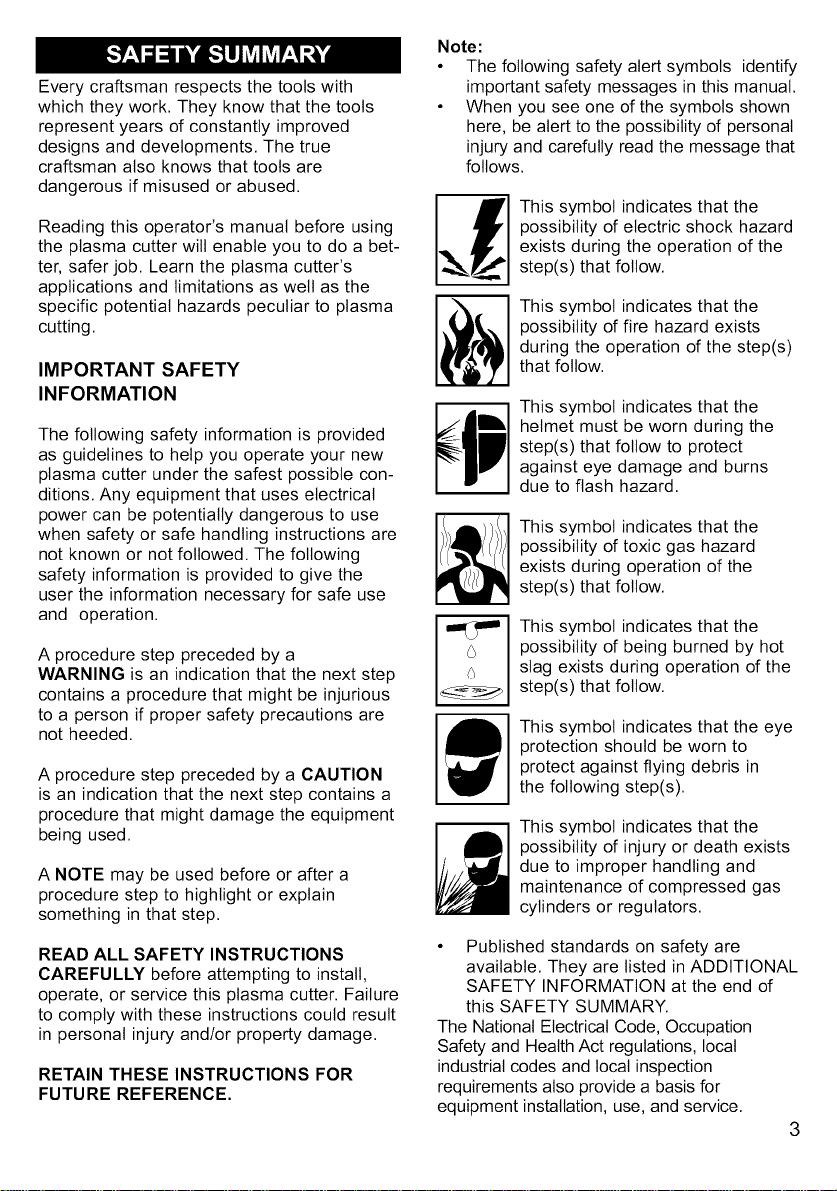
Note:
• The following safety alert symbols identify
important safety messages in this manual.
• When you see one of the symbols shown
here, be alert to the possibility of personal
injury and carefully read the message that
follows.
This symbol indicates that the
possibility of electric shock hazard
exists during the operation of the
step(s) that follow.
This symbol indicates that the
possibility of fire hazard exists
during the operation of the step(s)
that follow.
This symbol indicates that the
helmet must be worn during the
step(s) that follow to protect
against eye damage and burns
due to flash hazard.
This symbol indicates that the
possibility of toxic gas hazard
exists during operation of the
step(s) that follow.
This symbol indicates that the
possibility of being burned by hot
slag exists during operation of the
step(s) that follow.
This symbol indicates that the eye
protection should be worn to
protect against flying debris in
the following step(s).
This symbol indicates that the
possibility of injury or death exists
due to improper handling and
maintenance of compressed gas
cylinders or regulators.
Published standards on safety are
available. They are listed in ADDITIONAL
SAFETY INFORMATION at the end of
this SAFETY SUMMARY.
The National Electrical Code, Occupation
Safety and Health Act regulations, local
industrial codes and local inspection
requirements also provide a basis for
equipment installation, use, and service.
3
SHOCK HAZARDS
WARNING
ELECTRIC SHOCK CAN KILLt To reduce
the risk of death or serious injury from shock,
read, understand, and follow the following
safety instructions. In addition, make certain
that anyone else who uses this equipment,
or who is a bystander in the operating area
understands and follows these safety instruc-
tions as welt.
• IMPORTANT! TO REDUCE THE RISK
OF DEATH, INJURY, OR PROPERTY
DAMAGE, DO NOT ATTEMPT
OPERATION of this equipment until you
have read and understand the following
safety summary.
• Do not, in any manner, come into
physical contact with any part of the cut-
ting current circuit. The cutting current
circuit includes:
a. the work piece or any conductive
material in contact with it,
b. the ground clamp,
c. the torch,
d. any metal parts on the torch.
• Do not operate in a damp area or come
in contact with a moist or wet surface.
• Do not attempt to operate if any part of
clothing or body is wet.
• Do not allow the equipment to come in
contact with water or moisture.
• Do not drag cables, cutting torch, or
power cord through or allow them to
come into contact with water or moisture.
• Do not touch unit or attempt to turn unit on
or off if any part of the body or clothing is
moist or if you are in physical contact with
water or moisture.
• Do not attempt to plug the unit into the
power source if any part of body or cloth-
ing is moist, or if you are in physical
contact with water or moisture.
• Do not connect ground clamp to or cut on
electrical conduit.
• Do not alter power cord or power cord
plug in any way.
• Do not attempt to plug the unit
into the power source if the ground prong
on power cord plug is bent over, broken
off, or missing.
• Do not allow the unit to be connected to
the power source or attempt to operate if
the unit, cables, work area, or power cord
are exposed to any form of atmospheric
precipitation, or salt water spray.
• Do not carry coiled cables around shoul-
ders, or any other part of the body, when
they are plugged into the unit.
• Do not modify any wiring, ground
connections, switches, or fuses in this
equipment.
• Wear welding gloves to help insulate
hands from cutting circuit.
• Keep all liquid containers far enough
away from the unit and work area so that
if spilled, the liquid can not possibly come
in contact with any part of the unit or elec-
trical circuit.
• Replace any cracked or damaged parts
that are insulated or act as
insulators such as cables, power cord, or
electrode holder IMMEDIATELY.
FLASH HAZARDS
WARNING
ARC RAYS CAN INJURE EYES AND
BURN SKIN! To reduce the risk of injury
from arc rays, read, understand, and follow
the following safety instructions. In addition,
make certain that anyone else that uses this
equipment, or is a bystander in the work
area understands and follows these safety
instructions as well. Headshields and filter
should conform to ANSI Z87.1 standards.
• Do not look at an electric arc without proper
protection. A cutting arc is extremely bright
and intense and, with inadequate or no eye
protection, the retina can be burned, leav-
ing a permanent dark spot in the field of
vision. A shield or helmet with a number 8
shade filter tens (minimum) must be used.
• Do not strike an arc until all bystanders
and the operator have protective shields
and/or helmets in place.
• Do not wear a cracked or broken
helmet and replace any cracked or
broken filter lenses IMMEDIATELY.
Topreventanarcflashfrombeingcreat-
edoncontactdonotallowtheuninsutat-
edportionofthecuttingtorchtotouch
thegroundclamporgroundedwork.
Providebystanderswithshieldsor
helmetsfittedwitha#8shadefilterlens.
Wearprotectiveclothing.Theintense
lightofthecuttingarccanburntheskin
inmuchthesamewayasthesun,even
throughtight-weightclothing.Weardark
clothingofheavymaterial.Theshirtworn
shouldbelongsleevedandthecollar
keptbuttonedtoprotectchestandneck.
ProtectagainstREFLECTEDARCRAYS.
Arcrayscanbereflectedoffshinysurfaces
suchasaglossypaintedsurface,
aluminum,stainlesssteel,andglass.Itis
possibleforyoureyestobeinjuredby
reflectedarcraysevenwhenwearinga
protectivehelmetorshield.Ifworkingwith
areflectivesurfacebehindyou,arcrays
canbounceoffthesurface,thenoffthefil-
terlensontheinsideofyourhelmetor
shield,thenintoyoureyes.Ifareflective
backgroundexistsinyourworkarea,either
removeitorcoveritwithsomethingnon-
flammableandnon-reflective.Reflective
arcrayscanalsocauseskinbuminaddi-
tiontoeyeinjury.
FIRE HAZARDS
WARNING
FIRE OR EXPLOSION CAN CAUSE
DEATH, INJURY, AND PROPERTY DAM-
AGE! To reduce the risk of death, injury, or
property damage from fire or explosion, read,
understand, and follow the following safety
instructions. In addition, make certain that
anyone else that uses this equipment, or is a
bystander in the work area, understands and
follows these safety instructions as well.
REMEMBER!Plasma arc cutting, by nature
produces sparks, hot spatter, molten metal
drops, hot slag, and hot metal parts that can
start fires, burn skin, and damage eyes.
• Do not wear gloves or other clothing that
contains oil, grease, or other
flammable substances.
• Do not wear flammable hair
preparations.
• Do not work in an area until it is checked
and cleared of combustible and/or
flammable materials. BE AWARE that
sparks and slag can fly 35 feet and can
pass through small cracks and openings.
If work and combustibles cannot be
separated by a minimum of 35 feet,
protect against ignition with suitable,
snug-fitting, fire resistant, covers or
shields.
• Do not plasma cut on walls until checking
for and removing combustibles touching
the other side of the walls.
• Do not weld, cut, or perform other such
work on used barrels, drums, tanks, or
other containers that had contained a
flammable or toxic substance. The
techniques for removing flammable sub-
stance and vapors, to make a used
container safe for welding or cutting, are
quite complex and require special
education and training.
• Do not strike an arc on a compressed
gas or air cylinder or other pressure
vessel. Doing so wilt create a brittle area
that can result in a violent rupture
immediately or at a later time as a result
of rough handling.
• Do not weld or cut in an area where the
air may contain flammable dust (such as
grain dust), gas, or liquid vapors (such as
gasoline).
• Do not handle hot metal, such as the work
piece or electrode stubs, with bare hands.
• Wear leather gloves, heavy long sleeve
shirt, cuffless trousers, high-topped
shoes, helmet, and cap. As necessary,
use additional protective clothing such as
leather jacket or sleeves, fire resistant
leggings, or apron. Hot sparks or metal
can lodge in rolled up sleeves, trouser
cuffs, or pockets. Sleeves and collars
should be kept buttoned and pockets
eliminated from the shirt front.
• Have fire extinguisher equipment handy
for immediate use! A portable chemical
fire extinguisher, type ABC, is
recommended.
• Wear ear plugs when working overhead
to prevent spatter or slag from falling
into ear.
• Make sure work area has a good, solid,
5
safefloor,preferablyconcreteormason-
ry,nottiled,carpeted,ormadeofany
otherflammablematerial.
Protectflammablewalls,ceilings,
andfloorswithheatresistantcovers
orshields.
Checkworkareatomakesureitisfree
ofsparks,glowingmetalor
stag,andflamesbeforeleavingthe
workarea.
PLASMA ARC HAZARDS
WARNING
THE HEAT FROM THE PLASMA ARC CAN
CAUSE SERIOUS BURNS. THE FORCE
OF THE ARC ADDS GREATLY TO THE
BURN HAZARD. THE INTENSELY HOT
AND POWERFUL ARC CAN QUICKLY CUT
THROUGH GLOVES AND TISSUE.
• Keep away from the torch tip.
• Do not grip material near the cutting
path.
• The pilot arc can cause burns - keep
away from torch tip when trigger is
pressed.
• Wear proper flame retardant clothing cov-
ering all exposed body areas.
• Point torch away from your body and
toward work when pressing the
torch trigger
• Turn off power source and disconnect
input power before disassembling torch
or changing torch parts.
FUME HAZARDS
WARNING
FUMES, GASSES, AND VAPORS CAN
CAUSE DISCOMFORT, ILLNESS, AND
DEATH! To reduce the risk of discomfort,
illness, or death, read, understand, and
follow the following safety instructions. In
addition, make certain that anyone else that
uses this equipment or is a bystander in the
work area, understands and follows these
safety instructions as welt.
6
• Do not work in an area until it is checked
for adequate ventilation as described in
ANSI standard #Z49.1. If ventilation is
not adequate to exchange all fumes and
gasses generated during the cutting
process with fresh air, do not plasma cut
unless the operator and all bystanders
are wearing air-supplied respirators.
• Do not heat metals coated with, or that
contain, materials that produce toxic
fumes (such as galvanized steel), unless
the coating is removed. Make certain the
area is well ventilated, and the operator
and all bystanders are wearing air-sup-
plied respirators.
• Do not weld, cut, or heat lead, zinc,
cadmium, mercury, beryllium, or similar
metals without seeking professional
advice and inspection of the ventilation of
the work area. These metals produce
EXTREMELY TOXIC fumes which can
cause discomfort, illness, and death.
• Do not weld or cut in areas that are near
chlorinated solvents. Vapors from
chlorinated hydrocarbons, such as
trichtoroethytene and perchtoroethylene,
can be decomposed by the heat of an
electric arc or its ultraviolet radiation.
These actions can cause PHOSGENE, a
HIGHLY TOXIC gas to form, along with
other lung and eye-irritating gasses. Do
not weld or cut where these solvent
vapors can be drawn into the work area
or where the ultraviolet radiation can
penetrate to areas containing even very
small amounts of these vapors.
• Do not weld or cut in a confined area
unless it is being ventilated or the opera-
tor (and anyone else in the area) is wear-
ing an air-supplied respirator.
• Stop working if you develop momentary
eye, nose, or throat irritation as this
indicates inadequate ventilation. Stop
work and take necessary steps to
improve ventilation in the work area. Do
not resume work if physical discomfort
persists.
ADDITIONAL SAFETY
INFORMATION
For additional information concerning
welding and cutting safety, refer to the follow-
ing standards and comply with them as
applicable.
• ANSI Standard Z49.1 - SAFETY IN
WELDING AND CUTTING - obtainable
from the American Welding Society, 550
NW Le Jeune Road, Miami, FL 33126
Telephone (800) 443-9353,
Fax (305) 443-7559 - www.amweld.org
or www.aws.org
• ANSI Standard Z87.1 - SAFE PRAC-
TICE FOR OCCUPATION AND
EDUCATIONAL EYE AND FACE
PROTECTION - obtainable from the
American National Standards Institute,
11 West 42nd St., New York, NY 10036
Telephone (212) 642-4900,
Fax (212) 398-0023 - www.ansi.org
• NFPA Standard 51B - CUTTING AND
WELDING PROCESS - obtainable from
the National Fire Protection Association,
1 Batterymarch Park, P.O. Box 9101,
Quincy, MA 02269-9101
Telephone (617) 770-3000
Fax (617) 770-0700 - www.nfpa.org
• OSHAStandard 29 CFR, Part 1910,
Subpart Q., WELDING, CUTTING AND
BRAZING - obtainable from your state
OSHA office or U.S. Dept. of Labor
OSHA, Office of Public Affairs, Room
N3647, 200 Constitution Ave.,
Washington, DC 20210 - www.osha.gov
• CSA Standard Wl17.2 - Code for
SAFETY IN WELDING AND CUTTING.-
obtainable from Canadian Standards
Association, 178 Rexdale Blvd.,
Etobicoke, Ontario M9W 1R3 -
www.csa.ca
• American Welding Society Standard
A6.0. WELDING AND CUTTING
CONTAINERS WHICH HAVE HELD
COMBUSTIBLES. - obtainable from the
American Welding Society, 550 NW Le
Jeune Road, Miami, FL 33126
Telephone (800) 443-9353,
Fax (305) 443-7559 - www.amweld.org
or www.aws.org
7
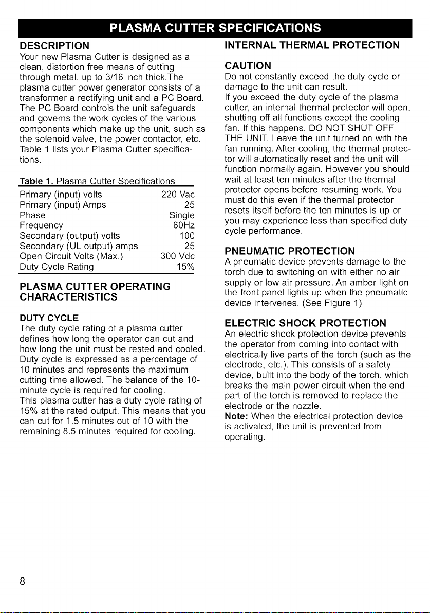
DESCRIPTION
Your new Plasma Cutter is designed as a
clean, distortion free means of cutting
through metal, up to 3/16 inch thick.The
plasma cutter power generator consists of a
transformer a rectifying unit and a PC Board.
The PC Board controls the unit safeguards
and governs the work cycles of the various
components which make up the unit, such as
the solenoid valve, the power contactor, etc.
Table 1 lists your Plasma Cutter specifica-
tions.
Table 1. Plasma Cutter Specifications
Primary (input) volts 220 Vac
Primary (input) Amps 25
Phase Single
Frequency 60Hz
Secondary (output) volts 100
Secondary (UL output) amps 25
Open Circuit Volts (Max.) 300 Vdc
Duty Cycle Rating 15%
PLASMA CUTTER OPERATING
CHARACTERISTICS
DUTY CYCLE
The duty cycle rating of a plasma cutter
defines how long the operator can cut and
how long the unit must be rested and cooled.
Duty cycle is expressed as a percentage of
10 minutes and represents the maximum
cutting time allowed. The balance of the 10-
minute cycle is required for cooling.
This plasma cutter has a duty cycle rating of
15% at the rated output. This means that you
can cut for 1.5 minutes out of 10 with the
remaining 8.5 minutes required for cooling.
INTERNAL THERMAL PROTECTION
CAUTION
Do not constantly exceed the duty cycle or
damage to the unit can result.
If you exceed the duty cycle of the plasma
cutter, an internal thermal protector wilt open,
shutting off all functions except the cooling
fan. If this happens, DO NOT SHUT OFF
THE UNIT. Leave the unit turned on with the
fan running. After cooling, the thermal protec-
tor wilt automatically reset and the unit will
function normally again. However you should
wait at least ten minutes after the thermal
protector opens before resuming work. You
must do this even if the thermal protector
resets itself before the ten minutes is up or
you may experience less than specified duty
cycle performance.
PNEUMATIC PROTECTION
A pneumatic device prevents damage to the
torch due to switching on with either no air
supply or low air pressure. An amber light on
the front panel lights up when the pneumatic
device intervenes. (See Figure 1)
ELECTRIC SHOCK PROTECTION
An electric shock protection device prevents
the operator from coming into contact with
electrically live parts of the torch (such as the
electrode, etc.). This consists of a safety
device, built into the body of the torch, which
breaks the main power circuit when the end
part of the torch is removed to replace the
electrode or the nozzle.
Note: When the electrical protection device
is activated, the unit is prevented from
operating.
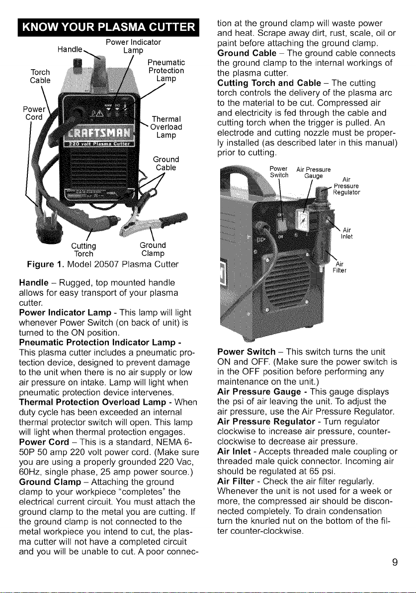
Torch
Cable
Power_
Cord
Power Indicator
Handle, Lamp
Pneumatic
Protection
Lamp
Thermal
Lamp
Ground
Cable
tion at the ground clamp will waste power
and heat. Scrape away dirt, rust, scale, oil or
paint before attaching the ground clamp.
Ground Cable - The ground cable connects
the ground clamp to the internal workings of
the plasma cutter.
Cutting Torch and Cable - The cutting
torch controls the delivery of the plasma arc
to the material to be cut. Compressed air
and electricity is fed through the cable and
cutting torch when the trigger is pulled. An
electrode and cutting nozzle must be proper-
ly installed (as described later in this manual)
prior to cutting.
Power Air Pressure
Switch Gauge Air
Pressure
Jlator
Cutting Ground
Torch Clamp
Figure 1. Model 20507 Plasma Cutter
Handle - Rugged, top mounted handle
allows for easy transport of your plasma
cutter.
Power Indicator Lamp - This lamp will light
whenever Power Switch (on back of unit) is
turned to the ON position.
Pneumatic Protection Indicator Lamp -
This plasma cutter includes a pneumatic pro-
tection device, designed to prevent damage
to the unit when there is no air supply or low
air pressure on intake. Lamp wilt light when
pneumatic protection device intervenes.
Thermal Protection Overload Lamp - When
duty cycle has been exceeded an internal
thermal protector switch will open. This lamp
will light when thermal protection engages.
Power Cord - This is a standard, NEMA 6-
50P 50 amp 220 volt power cord. (Make sure
you are using a properly grounded 220 Vac,
60Hz, single phase, 25 amp power source.)
Ground Clamp -Attaching the ground
clamp to your workpiece "completes" the
electrical current circuit. You must attach the
ground clamp to the metal you are cutting. If
the ground clamp is not connected to the
metal workpiece you intend to cut, the plas-
ma cutter will not have a completed circuit
and you will be unable to cut. A poor connec-
Inlet
Air
Filter
Power Switch - This switch turns the unit
ON and OFF. (Make sure the power switch is
in the OFF position before performing any
maintenance on the unit.)
Air Pressure Gauge - This gauge displays
the psi of air leaving the unit. To adjust the
air pressure, use the Air Pressure Regulator.
Air Pressure Regulator - Turn regulator
clockwise to increase air pressure, counter-
clockwise to decrease air pressure.
Air Inlet - Accepts threaded mate coupling or
threaded mate quick connector. Incoming air
should be regulated at 65 psi.
Air Filter - Check the air filter regularly.
Whenever the unit is not used for a week or
more, the compressed air should be discon-
nected completely. To drain condensation
turn the knurled nut on the bottom of the fit-
ter counter-clockwise.
9
SITE SELECTION
Select a clean, dry location with adequate
working space around all components.
The power supply is fan cooled by air flow
through the front and rear panels. This air
flow must not be obstructed. Provide at least
two feet of space in front of and behind the
unit to allow for free flow of air.
POWER SOURCE CONNECTION
POWER REQUIREMENTS
This plasma cutter is designed to operate on
a properly grounded 220 volt, 60Hz, single-
phase alternating current (ac) power source
fused with a 25 amp time delayed fuse or
circuit breaker, It is recommended that a
qualified electrician verify the ACTUAL
VOLTAGE at the receptacle into which the
plasma cutter will be plugged and confirm
that the receptacle is properly fused and
grounded. The use of the proper circuit size
can eliminate nuisance circuit breaker
tripping when working,
DO NOT OPERATE THIS UNIT if the
ACTUAL power source voltage is tess than
198 volts ac or greater than 240 volts ac,
Contact a qualified electrician if this problem
exists, Improper performance and/or damage
to the plasma cutter wilt result if operated on
inadequate or excessive power,
CONNECT TO POWER SOURCE
WARNING
High voltage danger from power source!
Consult a qualified electrician for proper
installation of receptacle at the power source,
This plasma cutter must be grounded while in
use to protect the operator from electrical
shock. If you are not sure if your outlet is prop-
erly grounded, have it checked by a qualified
electrician, Do not cut off the grounding prong
or alter the plug in any way and do not use
any adapters between the plasma cutter's
power cord and the power source receptacle,
Make sure the POWER switch is OFF then
connect your plasma cutter's power cord to a
properly grounded 220 Vac, 60 Hz, single
phase, 25 amp power source,
10
EXTENSION CORDS
For optimum performance, an extension cord
should not be used unless absolutely neces-
sary. If necessary, care must be taken in
selecting an extension cord appropriate for
use with your specific plasma cutter.
Select a properly grounded extension cord
that will mate directly with the power source
receptacle and the plasma cutter power cord
without the use of adapters. Make certain
that the extension cord is properly wired and
in good electrical condition.
Extension cords must be a #12 gauge cord
at the smallest. Do not use an extension
cord over 25 ft. in length.
ASSEMBLING THE PLASMA CUTTER
The following procedures describe the
process required to assemble, install, main-
tain, and prepare to work with your new plas-
ma cutter.
UNPACKING THE PLASMA CUTTER
1. Remove any cartons or bags containing
parts/accessories.
2. Open the cartons or bags packed with your
plasma cutter and inspect their contents for
damage.
3. Lay out the parts and compare them to
the packing list in Table 2 to familiarize
yourself with the parts and what they are
called. This wilt help you when reading
the manual.
PACKING LIST
Table 2 contains a list of the items you will
find packed in the carton.
Table 2. Packing List
ITEM QTY.
Plasma Cutter 1
Face Shield 1
Face Shield Handle 1
Shaded Lens 1
Top Mount Handle 1
Handle Screws 2
Parts Bag 1
Swirl Ring (1isinstalled) 2
Electrodes (1isinstalled) 2
Nozzles (1is installed) 2
1/4" Mate Coupler 1
Manual, Instruction 1
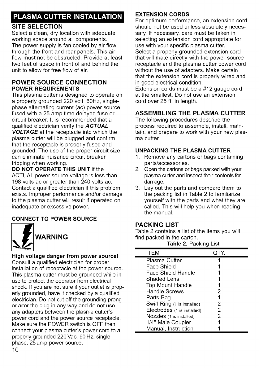
ASSEMBLE THE FACE SHIELD
1. Remove the lens retaining pegs and
shield handle nut from the arm of the
shield handle. (DO NOT DISCARD!)
2. Place the shaded lens into the space
provided on the inside of the face shield.
3. Screw the lens retaining nuts into the
holes to either side of the lens until they
are tight against lens.
4. Insert threaded peg on shield handle into
hole on face shield. Press firmly until
threaded peg and smaller peg below it
are locked into place.
5. From inside of shield, screw the shield
handle nut tightly onto peg threads.
CONNECTING THE AIR SUPPLY
1. Before attaching the air supply to the
plasma cutter, pull out the air pressure
regulator knob and turn it fully counter-
clockwise. This will set the regulator to its
lowest pressure. (see Figure 4)
÷
Figure 4
Lowering Regulator
Pressure
Figure 2. Face Shield Assembly
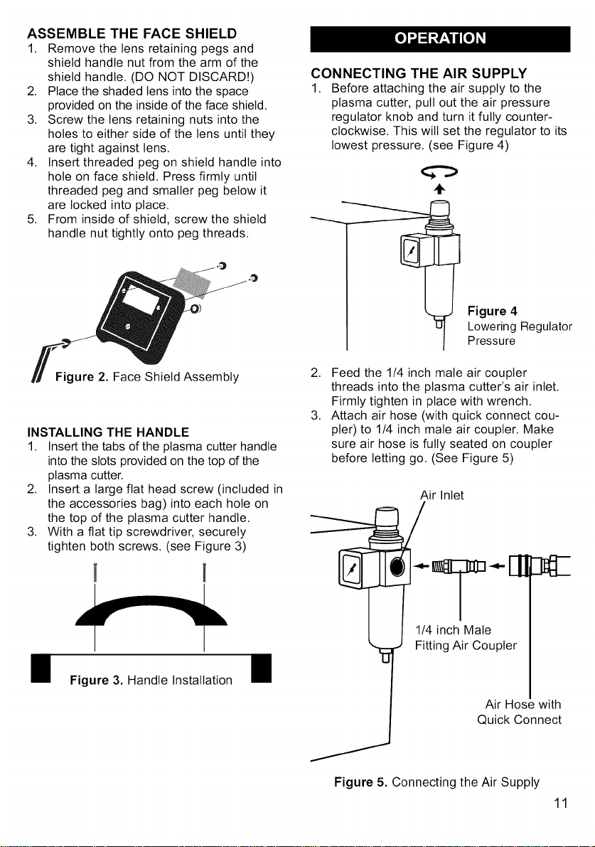
INSTALLING THE HANDLE
1. Insert the tabs of the plasma cutter handle
into the slots provided on the top of the
plasma cutter.
2. Insert a large flat head screw (included in
the accessories bag) into each hole on
the top of the plasma cutter handle.
3. With a fiat tip screwdriver, securely
tighten both screws. (see Figure 3)
Figure 3. Handle Installation
2. Feed the 1/4 inch male air coupler
threads into the plasma cutter's air inlet.
Firmly tighten in place with wrench.
3. Attach air hose (with quick connect cou-
pler) to 1/4 inch male air coupler. Make
sure air hose is fully seated on coupler
before letting go. (See Figure 5)
Air Inlet
Figure 5. Connecting the Air Supply
11
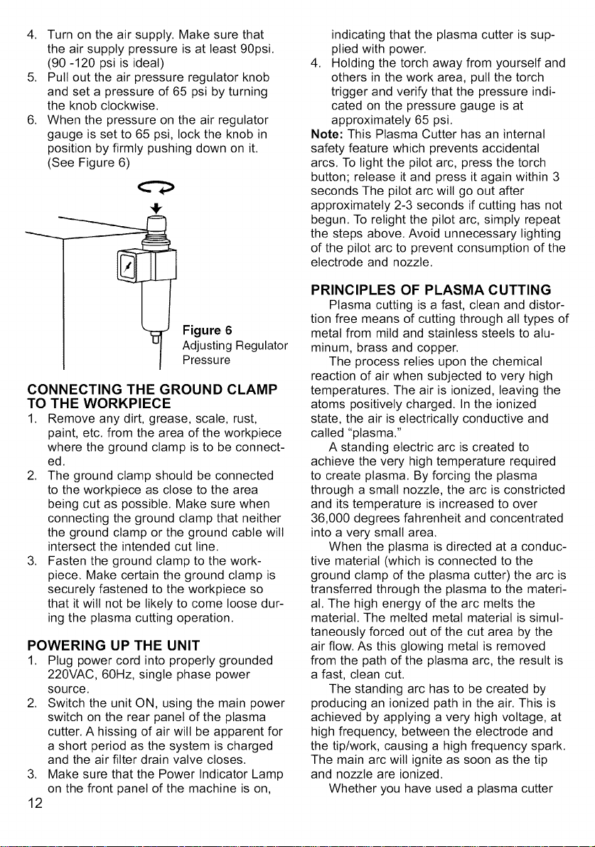
4. Turn on the air supply. Make sure that
the air supply pressure is at least 90psi.
(90 -120 psi is ideal)
5. Pull out the air pressure regulator knob
and set a pressure of 65 psi by turning
the knob clockwise.
6. When the pressure on the air regulator
gauge is set to 65 psi, lock the knob in
position by firmly pushing down on it.
(See Figure 6)
0
Figure 6
Adjusting Regulator
Pressure
CONNECTING THE GROUND CLAMP
TO THE WORKPIECE
1. Remove any dirt, grease, scale, rust,
paint, etc. from the area of the workpiece
where the ground clamp is to be connect-
ed.
2. The ground clamp should be connected
to the workpiece as close to the area
being cut as possible. Make sure when
connecting the ground clamp that neither
the ground clamp or the ground cable wilt
intersect the intended cut line.
3. Fasten the ground clamp to the work-
piece. Make certain the ground clamp is
securely fastened to the workpiece so
that it will not be likely to come loose dur-
ing the plasma cutting operation.
POWERING UP THE UNIT
1. Plug power cord into properly grounded
220VAC, 60Hz, single phase power
source.
2. Switch the unit ON, using the main power
switch on the rear panel of the plasma
cutter. A hissing of air wilt be apparent for
a short period as the system is charged
and the air filter drain valve closes.
Make sure that the Power Indicator Lamp
on the front panel of the machine is on,
3,
12
indicating that the plasma cutter is sup-
plied with power.
4. Holding the torch away from yourself and
others in the work area, pull the torch
trigger and verify that the pressure indi-
cated on the pressure gauge is at
approximately 65 psi.
Note: This Plasma Cutter has an internal
safety feature which prevents accidental
arcs. To light the pilot arc, press the torch
button; release it and press it again within 3
seconds The pilot arc will go out after
approximately 2-3 seconds if cutting has not
begun. To relight the pilot arc, simply repeat
the steps above. Avoid unnecessary lighting
of the pilot arc to prevent consumption of the
electrode and nozzle.
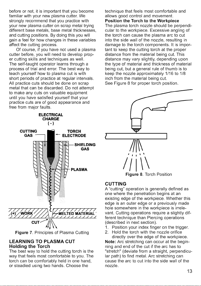
PRINCIPLES OF PLASMA CUTTING
Plasma cutting is a fast, clean and distor-
tion free means of cutting through all types of
metal from mild and stainless steels to alu-
minum, brass and copper.
The process relies upon the chemical
reaction of air when subjected to very high
temperatures. The air is ionized, leaving the
atoms positively charged. In the ionized
state, the air is electrically conductive and
called "plasma."
A standing electric arc is created to
achieve the very high temperature required
to create plasma. By forcing the plasma
through a small nozzle, the arc is constricted
and its temperature is increased to over
36,000 degrees fahrenheit and concentrated
into a very small area.
When the plasma is directed at a conduc-
tive material (which is connected to the
ground clamp of the plasma cutter) the arc is
transferred through the plasma to the materi-
al. The high energy of the arc melts the
material. The melted metal material is simul-
taneously forced out of the cut area by the
air flow. As this glowing metal is removed
from the path of the plasma arc, the result is
a fast, clean cut.
The standing arc has to be created by
producing an ionized path in the air. This is
achieved by applying a very high voltage, at
high frequency, between the electrode and
the tip/work, causing a high frequency spark.
The main arc will ignite as soon as the tip
and nozzle are ionized.
Whether you have used a plasma cutter
beforeornot,itisimportantthatyoubecome
familiarwithyournewplasmacutter.We
stronglyrecommendthatyoupracticewith
yournewplasmacutteronscrapmetaltrying
differentbasemetals,basemetalthicknesses,
andcuttingpositions.Bydoingthisyouwilt
gainafeelforhowchangesinthesevariables
affectthecuttingprocess.
Ofcourse,ifyouhavenotusedaplasma
cutterbefore,youwiltneedtodevelopprop-
ercuttingskillsandtechniquesaswell.
Theself-taughtoperatorlearnsthrougha
processoftrialanderror.Thebestwayto
teachyourselfhowtoplasmacutiswith
shortperiodsofpracticeatregularintervals.
Allpracticecutsshouldbedoneonscrap
metalthatcanbediscarded.Donotattempt
tomakeanycutsonvaluableequipment
untilyouhavesatisfiedyourselfthatyour
practicecutsareofgoodappearanceand
freefrommajorfaults.
ELECTRICAL
CHARGE
(-)
CUTTING TORCH
GAS -- ELECTRODE
-- SHIELDING
GAS
PLASMA
LEARNING TO PLASMA CUT
Holding the Torch
The best way to hold the cutting torch is the
way that feels most comfortable to you. The
torch can be comfortably held in one hand,
or steadied using two hands. Choose the
technique that feels most comfortable and
allows good control and movement.
Position the Torch to the Workpiece
The plasma torch nozzle should be perpendi-
cular to the workpiece. Excessive angling of
the torch can cause the plasma arc to cut
into the side wall of the nozzle, resulting in
damage to the torch components. It is impor-
tant to keep the cutting torch at the proper
distance from the material being cut. This
distance may vary slightly, depending upon
the type of material and thickness of material
being cut, but a general rule of thumb is to
keep the nozzle approximately 1/16 to 1/8
inch from the material being cut.
See Figure 8 for proper torch position.
I
I t
I I t
/I
Figure 8. Torch Position
CUTTING
A "cutting" operation is generally defined as
one where the penetration begins at an
existing edge of the workpiece. Whether this
edge is an outer edge or a previously made
hole somewhere in the workpiece is irrele-
vant. Cutting operations require a slightly dif-
ferent technique than Piercing operations
(described in next section).
1. Position your index finger on the trigger.
2. Hold the torch with the nozzle orifice
directly over the edge of the workpiece.
Note: Arc stretching can occur at the begin-
ning and end of the cut if the arc has to
"stretch" (deviate from a straight, perpendicu-
lar path) to find metal. Arc stretching can
cause the arc to cut into the side wall of the
nozzle.
13
WARNING
EXPOSURE TO A PLASMA ARC IS
EXTREMELY HARMFUL TO THE EYES
AND SKIN! Prolonged exposure to the plas-
ma arc can cause blindness and burns.
Never strike an arc or begin cutting until you
are adequately protected. Wear flameproof
welding gloves, a heavy long sleeved shirt,
cufftess trousers, high topped shoes and a
welding helmet.
3. With the torch in the starting position pull
and hold the trigger. The pilot arc will
come on until the cutting arc starts.
(Once on, the main arc stays on as long
as the trigger is held down, unless the
torch is withdrawn from the work or the
cutting motion is too stow.)
4. With the torch nozzle perpendicular to
the workpiece, pull (or push) the torch
across the area to be cut at a moderate,
steady pace.
5. To shut the torch off, simply release the
trigger.
Note: When the trigger is released and the
arc is extinguished, compressed air wilt con-
tinue to flow for a short period, in order to
cool the torch. DO NOT switch off the
machine until the air has stopped flowing or
damage to the torch may occur.
PIERCING
A "piercing" operation is defined as one
where the plasma arc creates a new pene-
tration in a workpiece. Unlike a Cutting oper-
ation, this means that there is no existing
edge to begin work from. The arc is forced
through the workpiece, thereby creating a
new "edge." After the initial penetration has
been made, a piercing operation is treated in
the same manner as a cutting operation.
1. Position your index finger on the trigger.
2. Hold the torch approximately 1/4 inch
above the workpiece, with the nozzle ori-
fice directly over the spot on the work-
piece where piercing is desired. It may
be necessary to angle the torch VERY
slightly while at this point to ensure that
sparks and/or spatter will not rebound
into the nozzle cap and nozzle.
14
WARNING
EXPOSURE TO A PLASMAARC IS
EXTREMELY HARMFUL TO THE EYES
AND SKIN! Prolonged exposure to the plas-
ma arc can cause blindness and burns.
Never strike an arc or begin cutting until you
are adequately protected. Wear flameproof
welding gloves, a heavy long sleeved shirt,
cuffless trousers, high topped shoes and a
welding helmet.
3. Pull and hold the torch trigger.
4. Lower the tip of the torch to within 1/8
inch of the workpiece or until the main
cutting arc transfers to the workpiece and
sparks start.
4. Ifyou intend only to pierce the workpiece,
release the trigger when the plasma
stream has penetrated the material.
5. For extended cuts, proceed to putt (or
push) the torch across the area to be cut
at a moderate, steady pace.
6. To shut the torch off, simply release the
trigger.
Note: When the trigger is released and the
arc is extinguished, compressed air will con-
tinue to flow for a short period, in order to
cool the torch. DO NOT switch off the
machine until the air has stopped flowing or
damage to the torch may occur.
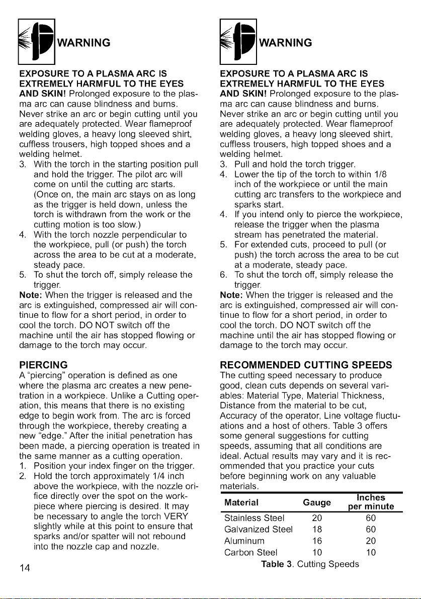
RECOMMENDED CUTTING SPEEDS
The cutting speed necessary to produce
good, clean cuts depends on several vari-
ables: Material Type, Material Thickness,
Distance from the material to be cut,
Accuracy of the operator, Line voltage fluctu-
ations and a host of others. Table 3 offers
some general suggestions for cutting
speeds, assuming that all conditions are
ideal. Actual results may vary and it is rec-
ommended that you practice your cuts
before beginning work on any valuable
materials.
Inches
Material Gauge per minute
Stainless Steel 20 60
Galvanized Steel 18 60
Aluminum 16 20
Carbon Steel 10 10
Table 3. Cutting Speeds
Thisplasmacutterhasbeenengineeredto
givemanyyearsoftroublefreeservicepro-
vidingthatafewverysimplestepsaretaken
toproperlymaintainit.
1. Keeptheunitcleanandfreeofdust.
Periodicallyusedry,compressedairto
cleandustdepositsfromfaceplateand
vents
2. Checktheairfilterregularly.Draincon-
densationbeforeeveryuse.
3. Keepthetorchcomponentsfreeofslag
atalltimes.Acloggednozzleorelec-
trodewiltnotallowproperairflowand
maydamagethetorch.
4. Keepconsumablesingoodworkingcon-
dition.Replaceconsumablesasneeded.
5. Formaregularhabitofcheckingelectri-
calcableandtorchcable.Ifanydamage
isapparent,thecableshouldbereplaced
immediately.
DRAINING CONDENSATION
Keeping a clean, dry air flow to your plasma
cutter is essential for reliable, trouble free
service. By regularly draining condensation
from the Air Filter you will promote a longer
life for consumable parts.
Note: If your plasma cutter will not be used
for extended periods of time, disconnect it
from the air supply.
1. Slowly turn the knurled drain valve on the
bottom of the Air Filter housing counter-
clockwise (as viewed from bottom of unit)
until it is fully open.
2. Allow all condensation to drain.
3. Retighten drain valve.
]
Valve
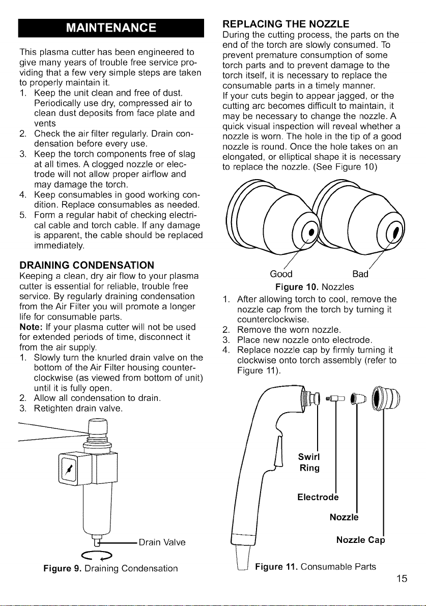
REPLACING THE NOZZLE
During the cutting process, the parts on the
end of the torch are slowly consumed. To
prevent premature consumption of some
torch parts and to prevent damage to the
torch itself, it is necessary to replace the
consumable parts in a timely manner.
If your cuts begin to appear jagged, or the
cutting arc becomes difficult to maintain, it
may be necessary to change the nozzle. A
quick visual inspection wilt reveal whether a
nozzle is worn. The hole in the tip of a good
nozzle is round. Once the hole takes on an
elongated, or elliptical shape it is necessary
to replace the nozzle. (See Figure 10)
Good Bad
Figure 10. Nozzles
1. After allowing torch to coot, remove the
nozzle cap from the torch by turning it
counterclockwise.
2. Remove the worn nozzle.
3. Place new nozzle onto electrode.
4. Replace nozzle cap by firmly turning it
clockwise onto torch assembly (refer to
Figure 11).
Swirl
Ring
Electrode
Nozzle
Nozzle Cap
Figure 11. Consumable Parts
Figure 9. Draining Condensation
15
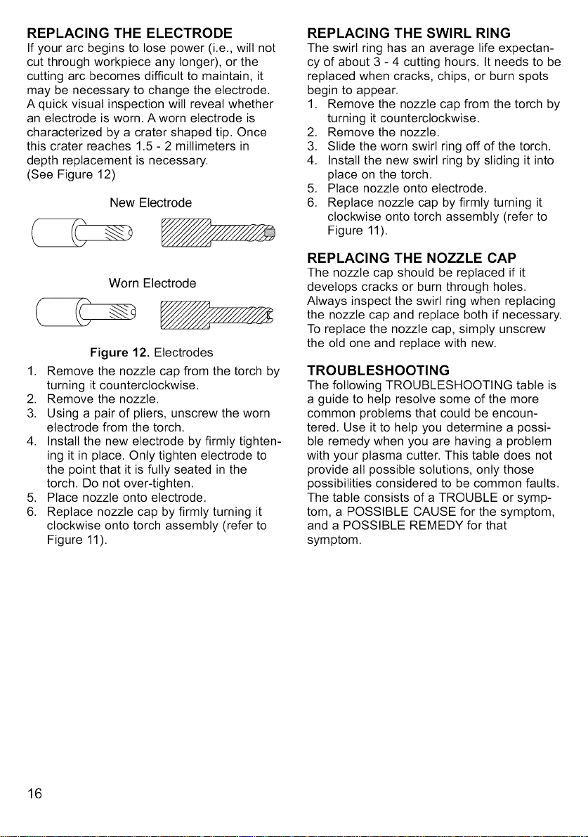
REPLACING THE ELECTRODE
If your arc begins to lose power (i.e., will not
cut through workpiece any longer), or the
cutting arc becomes difficult to maintain, it
may be necessary to change the electrode.
A quick visual inspection will reveal whether
an electrode is worn. A worn electrode is
characterized by a crater shaped tip. Once
this crater reaches 1.5 - 2 millimeters in
depth replacement is necessary.
(See Figure 12)
New Electrode
Worn Electrode
Figure 12. Electrodes
1. Remove the nozzle cap from the torch by
turning it counterclockwise.
2. Remove the nozzle.
3. Using a pair of pliers, unscrew the worn
electrode from the torch.
4. Install the new electrode by firmly tighten-
ing it in place. Only tighten electrode to
the point that it is fully seated in the
torch. Do not over-tighten.
5. Place nozzle onto electrode.
6. Replace nozzle cap by firmly turning it
clockwise onto torch assembly (refer to
Figure 11).
REPLACING THE SWIRL RING
The swirl ring has an average life expectan-
cy of about 3 - 4 cutting hours. It needs to be
replaced when cracks, chips, or burn spots
begin to appear.
1. Remove the nozzle cap from the torch by
turning it counterclockwise.
2. Remove the nozzle.
3. Slide the worn swirl ring off of the torch.
4. Install the new swirl ring by sliding it into
place on the torch.
5. Place nozzle onto electrode.
6. Replace nozzle cap by firmly turning it
clockwise onto torch assembly (refer to
Figure 11).
REPLACING THE NOZZLE CAP
The nozzle cap should be replaced if it
develops cracks or burn through holes.
Always inspect the swirl ring when replacing
the nozzle cap and replace both if necessary.
To replace the nozzle cap, simply unscrew
the old one and replace with new.
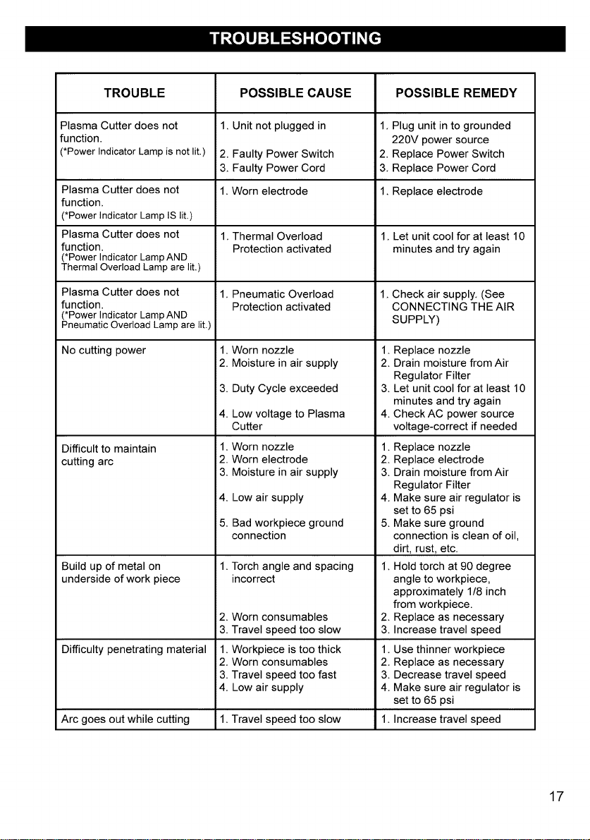
TROUBLESHOOTING
The following TROUBLESHOOTING table is
a guide to help resolve some of the more
common problems that could be encoun-
tered. Use it to help you determine a possi-
ble remedy when you are having a problem
with your plasma cutter. This table does not
provide all possible solutions, only those
possibilities considered to be common faults.
The table consists of a TROUBLE or symp-
tom, a POSSIBLE CAUSE for the symptom,
and a POSSIBLE REMEDY for that
symptom.
16
TROUBLE
Plasma Cutter does not
function.
(*Power Indicator Lampis notlit.)
Plasma Cutter does not
function,
(*Power Indicator Lamp IS lit.)
Plasma Cutter does not
function.
(*Power Indicator Lamp AND
Thermal Overload Lamp are lit.)
Plasma Cutter does not
function.
(*Power Indicator Lamp AND
Pneumatic Overload Lamp are lit.)
No cutting power
Difficult to maintain
cutting arc
Build up of metal on
underside of work piece
POSSIBLE CAUSE
1, Unit not plugged in
2. Faulty Power Switch
3. Faulty Power Cord
1. Worn electrode
1. Thermal Overload
Protection activated
1. Pneumatic Overload
Protection activated
1. Worn nozzle
2. Moisture in air supply
3. Duty Cycle exceeded
4. Low voltage to Plasma
Cutter
1. Worn nozzle
2. Worn electrode
3. Moisture in air supply
4. Low air supply
5. Bad workpiece ground
connection
1. Torch angle and spacing
incorrect
2. Worn consumables 2.
3. Travel speed too slow 3.
Difficulty penetrating material 1. Workpiece is too thick 1.
2. Worn consumables 2.
3. Travel speed too fast 3.
4. Low air supply 4.
Arc goes out while cutting 1. Travel speed too slow 1.
POSSIBLE REMEDY
1, Plug unit in to grounded
220V power source
2. Replace Power Switch
3. Replace Power Cord
1. Replace electrode
1_Let unit cool for at least 10
minutes and try again
1_Check air supply. (See
CONNECTING THE AIR
SUPPLY)
1. Replace nozzle
2. Drain moisture from Air
Regulator Filter
3. Let unit cool for at least 10
minutes and try again
4. Check AC power source
voltage-correct if needed
1. Replace nozzle
2. Replace electrode
3. Drain moisture from Air
Regulator Filter
4. Make sure air regulator is
set to 65 psi
5. Make sure ground
connection is clean of oil,
dirt, rust, etc.
1. Hold torch at 90 degree
angle to workpiece,
approximately 1/8 inch
from workpiece.
Replace as necessary
Increase travel speed
Use thinner workpiece
Replace as necessary
Decrease travel speed
Make sure air regulator is
set to 65 psi
Increase travel speed
17
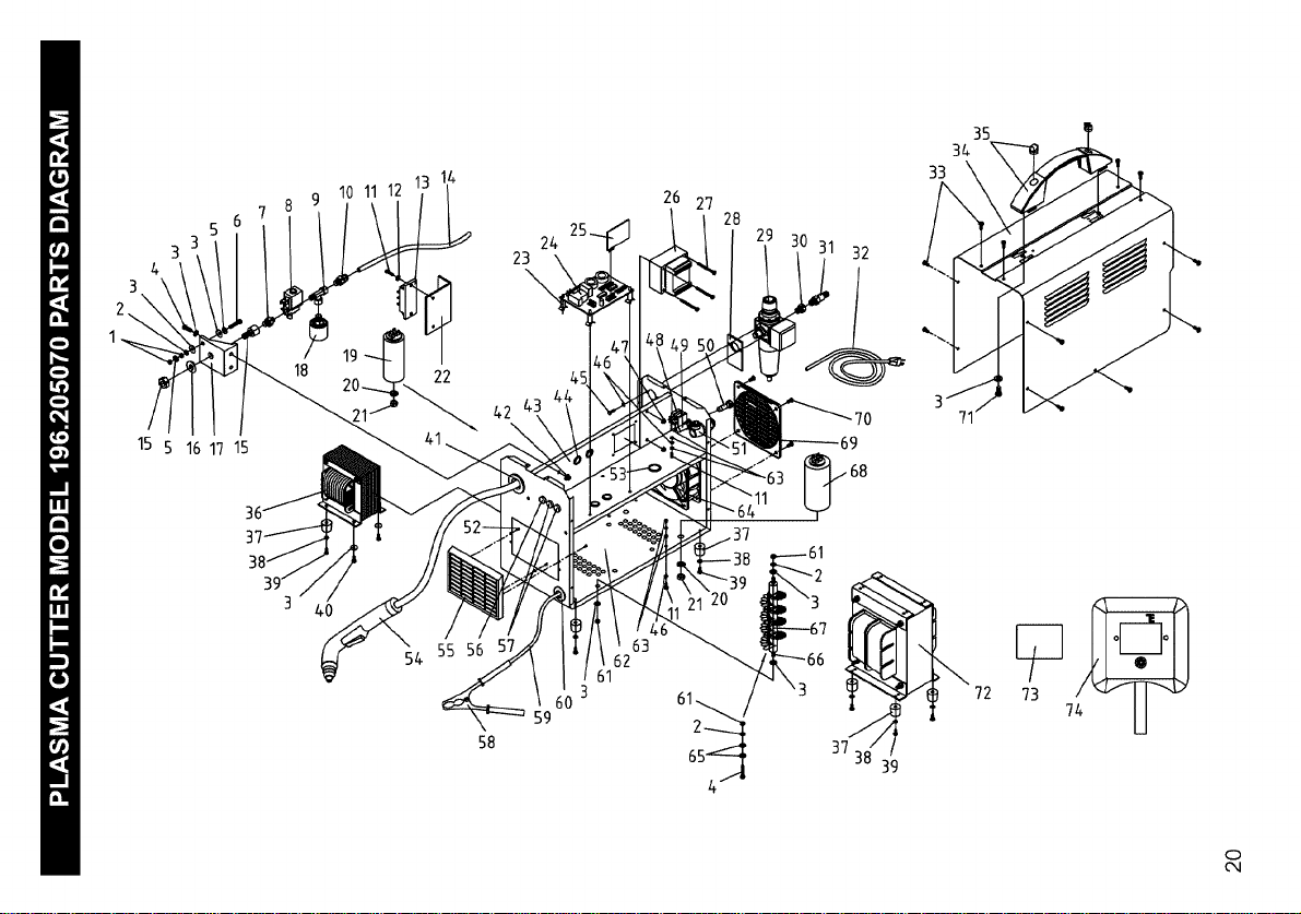
18
2_V
NO,
Ol
O2
o3
o4
05
06
o7
08
09
lO
11
12
13
14
15
16
17
18
19
20
21
22
23
24
25
26
27
28
29
3o
31
32
33
34
35
36
37
38
39
40
41
42
43
44
45
46
47
48
49
50
51
52
53
54
55
56
57
58
59
60
61
62
63
64
65
66
67
68
69
70
71
72
73
74
Code
WE20507-21045004
WE20507-21035004
WE20507-21030011
WE20507-21000020
WE20507-21050003
WE20507-21040011
WE20507-22910007
WE20507-22900002
WE20507-22910037
WE20507-22910060
WE20507-21005012
WE20507-21030002
WE20507-22400093
WE20507-10900008
WE20507-23015001
WE20507-21050013
WE20507-21890020
WE20507-22900005
WE20507-22315007
WE20507-21035005
WE20507-21025011
WE20507-33820071
WE20507-21690120
WE20507-22720022
WE20507-22720012
WE20507-44140055
WE20507-21020044
WE20507-30490047
WE20507-22905072
WE20507-22910068
WE20507-22910074
WE20507-20220120
WE20507-21020017
WE20507-33705374
WE20507-21600030
WE20507-44135009
WE20507-21610001
WE20507-21030003
WE20507-21020021
WE20507-21020025
WE20507-21605023
WE20507-21025028
WE20507-33720122
WE20507-21605007
WE20507-21000002
WE20507-21035002
WE20507-21025029
WE20507-22200025
WE20507-22220016
WE20507-22220021
WE20507-21605036
WE20507-21020002
WE20507-21605023
WE20507-23010049
WE20507-21690286
WE20507-22610004
WE20507-22610011
WE20507-22110005
WE20507-43210028
WE20507-21605032
WE20507-21025008
WE20507-33700200
WE20507-21025004
WE20507-22800021
WE20507-21030004
WE20507-21015018
WE20507-22305003
WE20507-22315008
WE20507-21690287
WE20507-21020026
WE20507-21020032
WE20507-44130066
WE20507-21905007
WE20507-21905002
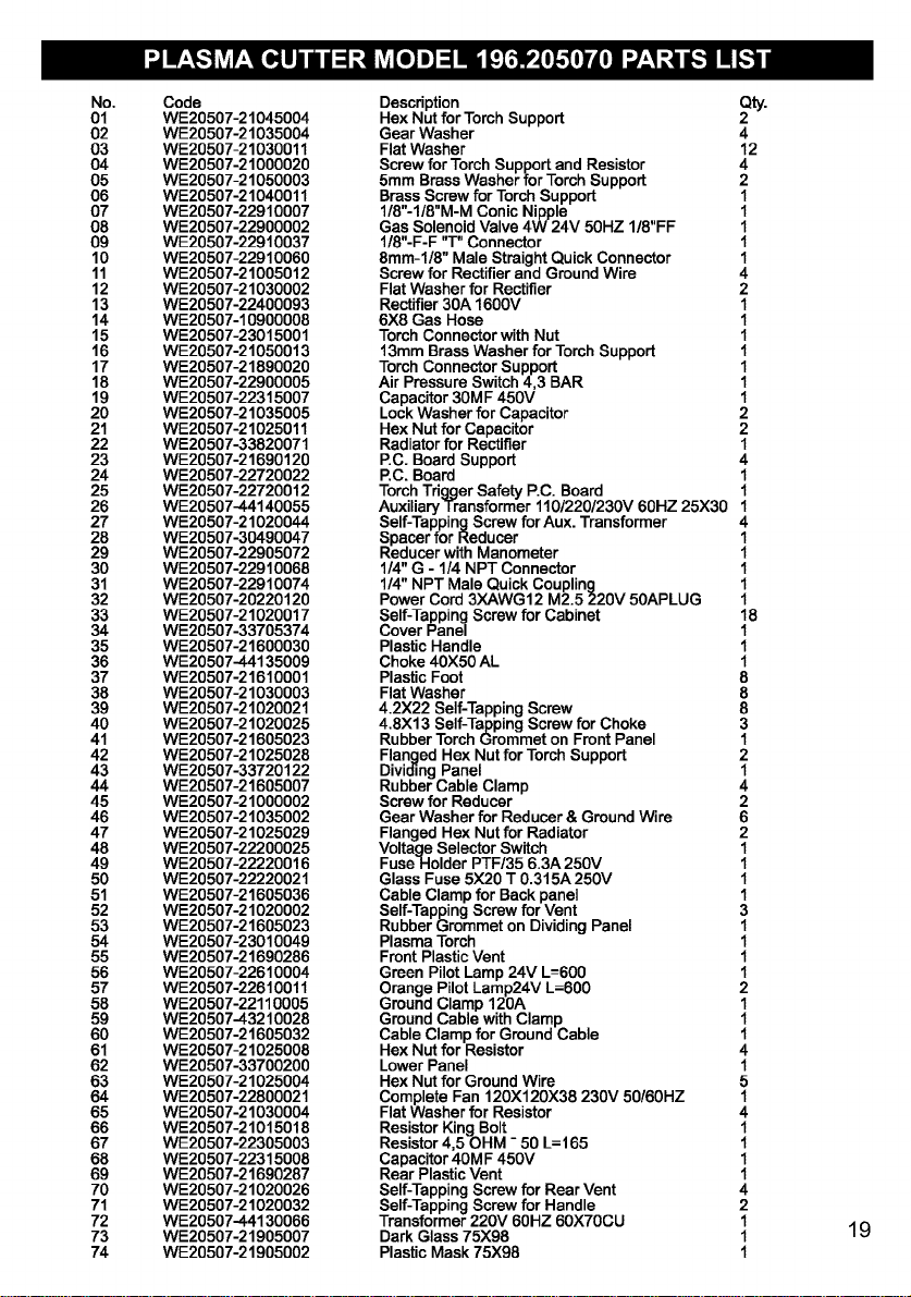
Description Qty.
Hex Nut for Torch Support
Gear Washer 4
Flat Washer 12
Screwfor TorchSupportand Resistor 4
5mm Brass Washer for TorchSupport 2
Brass Screw for Torch Support 1
1/8"-1/8"M-M Conic Nipple 1
Gas Solenoid Valve 4W 24V 50HZ I/8"FF 1
I/8"-F-F "T" Connector 1
8mm-1/8" Male StraightQuick Connector 1
Screwfor Rectifier and Ground Wire 4
Flat Washer for Rectifier 2
Rectifier 30A 1600V 1
6X8 Gas Hose 1
Torch Connector with Nut 1
13mm BrassWasher for TorchSupport 1
TorchConnectorSupport 1
AirPressureSwitch 4,3 BAR 1
Capacitor30M F 450V 1
LockWasher for Capacitor 2
Hex Nut for Capacitor 2
Radiator for Rectifier 1
P.C.Board Support 4
P.C.Board 1
TorchTriggerSafety P.C. Board 1
Auxiliary Trensformer110/220/230V 60HZ 25X30 1
Self-TappingScrewfor Aux. Transformer 4
Spacer for Reducer 1
Reducer withManometer 1
1/4" G - 1/4 NPT Connector 1
1/4" NPT Male Quick Coupling 1
Power Cord 3XAWG12 M2.5 220V 50APLUG 1
Self-TappingScrewfor Cabinet 18
Cover Panel 1
Plastic Handle 1
Choke 40X50 AL 1
Plastic Foot 8
Flat Washer 8
4.2X22 Self-TappingScrew 8
4.8X13 Self-TappingScrewfor Choke 3
Rubber TorchGrommet on FrontPanel 1
Flanged Hex Nut for TorchSupport 2
DividingPanel 1
Rubber Cable Clamp 4
Screwfor Reducer 2
Gear Washer for Reducer & Ground Wire 6
Flanged Hex Nut for Radiator 2
VoltageSelector Switch 1
FuseHolder PTF/35 6.3A 250V 1
Glass Fuse 5)(20 T 0.315A 250V 1
Cable Clamp for Back panel 1
Self-TappingScrewfor Vent 3
Rubber Grommet on DividingPanel 1
Plasma Torch 1
FrontPlastic Vent 1
Green PilotLamp 24V L--600 1
Orange PilotLamp24V L=600 2
GroundClamp 120A 1
GroundCable withClamp 1
Cable Clamp for Ground Cable 1
Hex Nut for Resistor 4
LowerPanel 1
Hex Nut for Ground Wire 5
Complete Fan 120X120X38 230V 50/60HZ 1
Flat Washer for Resistor 4
ResistorKing Bolt 1
Resistor4,5 OHM - 50 L=165 1
Capacitor40M F 450V 1
Rear PlasticVent 1
Self-TappingScrewfor Rear Vent 4
Self-TappingScrewfor Handle 2
Transformer220V 60HZ 60X70GU 1
Dark Glass75)(98 1
Plastic Mask 75X98 1
19
3
4
15 5 16 17 15
18
10 11 12
19
22
24
23
\
42\
26 27
28
32
54 55 56
58
59
62
61
3
65
72
73 7
CD
Cq
]
5_
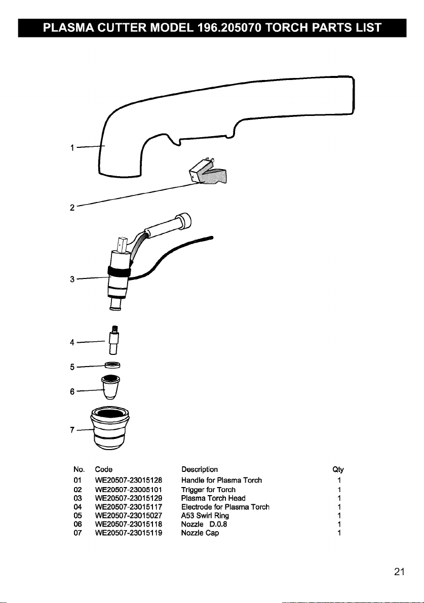
No. Code Description
01 WE20507-23015128 Handlefor Plasma Torch
02 WE20507-23005101 Triggerfor Torch
03 WE20507-23015129 PlasmaTorch Head
04 WE20507-23015117 Electrodefor PlasmaTorch
05 WE20507-23015027 A53 Swirl Ring
06 WE20507-23015118 Nozzle D.0.8
07 WE20507-23015119 Nozzle Cap
Qty
1
1
1
1
1
1
1
21

Garantia Limitada de Craftsman ...... 23
Introduccion ...................... 23
Resumen de Seguridad ............. 24
Informaci6n de Seguridad ........... 24
Riesgos de Descarga El6ctrica ....... 25
Riesgos de Destetlo del Arco ........ 25
Riesgos de Incendio ............... 26
Riesgos del Arco de Plasma ........ 27
Riesgos de Vapores ............... 27
Informaci6n Adicional de Seguridad ...28
Especificaciones de la Cortadora
de Plasma ........................ 29
Descripci6n ...................... 29
Caracteristicas de Operaci6n ........ 29
Cicto de Funcionamiento .......... 29
Protecci6n T6rmica Interna ........ 29
Protecci6n Neumatica ............ 29
Protecci6n contra Descarga EI6ctrica .29
Conozca su Cortadora de Plasma ..... 30
Instalacion de la Cortadora
de Plasma ........................ 31
Ubicaci6n ........................ 31
Conexi6n al Suministro EI6ctrico ..... 31
Electricidad Requerida ............ 31
Conexi6n al Tomacorriente ........ 31
Cordones de Extensi6n ........... 31
Armado de la Cortadora de Plasma ...31
Desempacado de la Cortadora
de Plasma ..................... 31
Lista de Empaque ............... 31
Armado de la Mascara para Soldar..32
Instalaci6n de la Manija ........... 32
Operacion ........................ 32
Conexi6n del Suministro de Aire ...... 32
Conexi6n de la Pinza de Tierra
a la Pieza de Trabajo ............... 33
Encendido de la Unidad ............ 33
Principios det Corte con Plasma ...... 33
Aprendiendo a Cortar con Plasma .... 34
Sosteniendo el Soplete ........... 34
Posicionado et Soptete en
la Pieza de Trabajo .............. 34
Cortando ........................ 34
Perforando ....................... 35
Velocidades de Corte Recomendadas ...35
Mantenimiento ..................... 36
Drenaje de la Condensaci6n ......... 36
Reemplazo del Pico ................ 36
Reemplazo det Electrodo ........... 37
Reemptazo del Anillo de Turbutencia . .37
Reemplazo de la Tapa del Pico ....... 37
Diagn6stico de Probtemas ........... 37
Diagrama Electrico ................. 39
Lista de Partes .................... 40
Garantia Limitada de Tres Ahos de la Cortadora de Plasma Craftsman
Por tres a_os desde la fecha de compra, si cuatquier parte de esta cortadora de plasma, con
excepci6n de la pistola y los cables, fatla debido a un defecto de material o fabricaci6n,
ret6rnela a su Centro Sears de Reparaci6n y Repuestos mas cercano, y sera reparada sin
cargo. Sears reparara la pistola o los cables gratis por un a_o desde la fecha de compra. Esta
garantia no cubre partes desechables como los etectrodos, picos o tapas de picos, las que se
consumen durante la operaci6n normal de la cortadora de plasma. Esta garantia solo es
vatida mientras et producto se utilice en los EE.UU. Esta garantia le otorga derechos legales
especificos, y usted puede tambi6n tener otros derechos los que varian de estado a estado.
Sears, Roebuck and Co., D/817WA, Hoffman Estates, IL 60179
Este manual det usuario le proporciona toda la informaci6n especifica que necesita para poder
utilizar su Cortadora de Plasma de forma segura y efectiva. Contiene instrucciones de
seguridad, configuraci6n, instataci6n y operaci6n de la Cortadora de Plasma.
23
Todo artesano respeta las herramientas con las
que trabaja. Sabe que las herramientas
representan afios de mejoras y desarroNo
constantes. Un verdadero artesano tambi6n
sabe que las herramientas son peligrosas si se
usan mal o se maltratan.
El leer este manual det usuario antes de
utilizar el cortador de plasma le permitira
realizar un trabajo mejor y mas seguro.
Aprenda las apticaciones y limitaciones del
cortador de plasma asi como los petigros
potenciales especificos referentes a
cortadores de plasma.
INFORMACION IMPORTANTE
DE SEGURIDAD
La siguiente informaci6n de seguridad se
proporciona como una guia para ayudarto a
operar su nuevo cortador de plasma bajo tas
condiciones mas seguras posibles. Cualquier
equipo que use energfa el6ctrica puede ser
potencialmente peligroso cuando no se siguen o
se desconocen las instrucciones de seguridad y
de manipulaci6n. A continuaci6n se provee la
informaci6n necesaria para que el usuario opere
y use la unidad en forma segura.
Un aviso de ADVERTENCIA precediendo un
paso de un procedimiento indica que el siguiente
paso podrfa lesionar a la persona si es que no
se cumplen con las precauciones de seguridad
apropiadas.
Un aviso de PRECAUCION precediendo un
paso de un procedimiento indica que el siguiente
paso podrfa dafiar el equipo en uso.
Se puede usar una NOTA antes o despu6s de
un paso en un procedimiento para remarcar o
explicar algo propio de ese paso.
LEER TODAS LAS INSTRUCCIONES DE
SEGURIDAD CUIDADOSAMENTE antes de
intentar instalar, operar o darle servicio a esta
soldadora. Ignorar estas instrucciones, podrfa
causar lesiones personales y/o dafios a la
propiedad.
CONSERVAR ESTAS INSTRUCClONES PARA
REFERENClA FUTURA.
Nota:
• Los siguientes sfmbolos de alerta de seguridad
24
identifican mensajes de seguridad importantes
en este manual.
• Cuando vea uno de estos sfmbolos que se
indicana continuaci6n, est6 alerta a la
posibilidad de lesiones personales y lea
cuidadosamente el mensaje que le sigue.
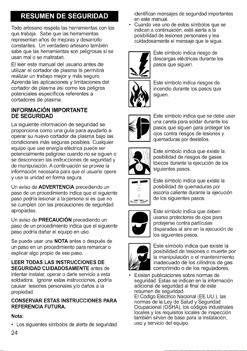
m
m
Este sfmbolo indica riesgo de
descargas el6ctricas durante los
pasos que siguen.
Este sfmbolo indica riesgos de
incendio durante los pasos que
siguen.
Este sfmbolo indica que se debe usar
una careta para soldar durante los
pasos que siguen para proteger los
ojos contra riesgos de lesiones y
quemaduras por destellos.
Este sfmbolo indica que existe la
posibilidad de riesgos de gases
t6xicos durante la ejecuci6n de los
siguientes pasos.
Este sfmbolo indica que existe la
posibilidad de quemaduras por
escoria caliente durante la ejecuci6n
de los siguientes pasos.
Este sfmbolo indica que deben
usarse protectores de ojos para
protejerse contra partfculas
disparadas al aire en la ejecuci6n de
los siguientes pasos.
Este simboto indica que existe la
posibilidad de lesiones o muerte por
la manipulaci6n o et mantenimiento
inadecuado de los citindros de gas
comprimido o de los regutadores.
• Existen publicaciones sobre normas de
seguridad. Estas se indican en la informaci6n
adicional de seguridad al final de este
resumen de seguridad.
El C6digo EI6ctrico Nacional (EE.UU.), las
normas de la Ley de Salud y Seguridad
Ocupacional (OSHA), los c6digos industriales
locales y los requisitos locales de inspecci6n
tambi6n sirven de base para la instalaci6n,
uso y servicio del equipo.
RIESGOS DE CHOQUE ELI_CTRICO
_ ADVERTENCIA
iLAS DESCARGAS EL#CTRICAS
PUEDEN CAUSAR LA MUERTE! Para
reducir el riesgo de muerte o heridas graves
por descargas, lea, entienda y siga las
siguientes instrucciones de seguridad.
Ademas, asegQrese de que cuatquier otra
persona que utiNce el equipo, o que est6
presente en et area de operaci6n tambi6n
entienda y siga estas instrucciones de
seguridad.
• ilMPORTANTE! PARA REDUCIR EL
RIESGO DE MUERTE, HERIDAS, O
DANOS MATERIALES, NO INTENTE LA
OPERACION de este equipo hasta que
haya tefdo y entendido et siguiente
resumen de seguridad.
• Nunca, de ninguna manera, entre en
contacto fisico con atguna de las partes
det circuito de corte. El circuito de corte
incluye:
a. las piezas de trabajo de cuatquier
material conductor en contacto con 61,
b. la pinza de tierra,
c. el soplete,
d. cualquier parte material det soptete.
• Nunca trabaje en un area h6meda o entre
en contacto con una superficie h6meda.
• No intente utiNzar la unidad si atguna parte
de su ropa o cuerpo esta hQmeda.
• No permita que el equipo entre en
contacto con agua o humedad.
• No arrastre los cables, soptete o cable de
aNmentaci6n o permita que entren en
contacto con agua o humedad.
• No toque la unidad ni intente encenderla o
apagarla si atguna parte de su cuerpo o
ropa esta hQmeda o si se encuentra en
contacto fisico con agua o humedad.
• No intente enchufar ta unidad en un
tomacorriente si atguna parte de su cuerpo
o ropa esta h6meda o si se encuentra en
contacto fisico con agua o humedad.
• No conecte la pinza de tierra a un caSo
el6ctrico o intente cortarlo.
• No modifique et cable de alimentaci6n o el
enchufe de ninguna forma.
• No intente enchufar la unidad en un
tomacorriente si et terminal de tierra del
enchufe esta dobtado, roto o se ha satido.
• No permita que se enchufe la unidad at
tomacorriente o que se intente usar si la
unidad, cables, area de trabajo, o cable de
atimentaci6n estan expuestos a cualquier
forma de precipitaci6n atmosf6rica, o rocfo
de agua salada.
• No lleve los cables enroscados en sus
hombros, o ninguna otra parte det cuerpo,
cuando est6n enchufados a la unidad.
• No modifique ningQn cableado, conexiones
a tierra, Naves o fusibles det equipo.
• Use guantes de soldador para aistar las
manos del circuito de corte.
• Mantenga todos los recipientes de Nquidos
suficientemente alejados de la unidad y el
area de trabajo de manera que si se
derraman, et Nquido no pueda entrar en
contacto con ninguna parte de la unidad o
circuito et6ctrico.
• Reemptace INMEDIATAMENTE todas las
partes rajadas o da_adas que est6n
aistadas o act6en como aislador tales
como cables, cable de atimentaci6n o
soporte del electrodo.
DESTELLOS PELIGROSOS
_ ADVERTENCIA
iLOS RAYOS DE LOS ARCOS PUEDEN
LESIONAR LOS OJOS Y QUEMAR LA
PIEL! Para reducir el riesgo de heridas por
rayos, lea, entienda y siga las siguientes
instrucciones de seguridad. Ademas,
aseg6rese de que cuatquier otra persona
que utitice et equipo, o que est6 presente en
el area de operaci6n tambi6n entienda y siga
estas instrucciones de seguridad. Los
protectores y filtros deben cumptir con las
normas ANSI Z87.1.
• No mire directamente a un arco el6ctrico
sin la protecci6n adecuada. Un arco de
corte es extremadamente britlante e
intenso y con protecci6n ocular
inadecuada o nula, puede quemarse la
retina, dejando un punto oscuro
permanente en et campo visual. Debe
utilizarse una mascara o casco con un
lente de protecci6n oscuro n6mero 8
(como mfnimo).
• No produzca un arco hasta que todos los
observadores y el operador se hayan
colocado los protectores y/o cascos.
25
• Nouseuncascorajadoorotoyreemptace
INMEDIATAMENTEcualquierlentedefiltro
rajadooroto.
• Paraprevenirlaformaci6ndeunarco
el6ctriconopermitaquelapartesin
aistamientodelapistoladecortetoqueta
pinzadetierraolapiezaconectadaatierra.
• Proporcionealosespectadoresmascaraso
cascosconlentesoscurosdeprotecci6n#8.
• Useropaprotectora.Laluzintensadelarco
decortepuedequemarlapieldelamisma
formaquelohaceelsol,inclusoatrav6s
deropagruesa.Useropaoscurade
materialpesado.Sedebeutilizaruna
camisademangaslargasymantener
abotonadoelcuelloparaprotegerelpecho
yelcuelto.
• Prot6jasecontraRAYOSDEARCOS
REFLEJADOS.Losrayosdelosarcos
puedenreflejarseensuperficiesbritlantes
comosuperficiesconpinturabrittante,
aluminio,aceroinoxidabteyvidrio.Susojos
puedendaSarseporrayosdearcos
reflejados,inclusoalusaruncascoo
mascaradeprotecci6n.AItrabajarconuna
superficiereflectantedetrassuyo,losrayos
delosarcospuedenrebotarenesa
superficie,luegoenelinteriordetlente
protectordesucascoyIlegarasusojos.Si
suareadetrabajotieneunfondoreflectante,
tratedesacarloocubrirloconalgoqueno
reflejeyquenoseainflamabte.Losrayosde
arcoreflejadostambi6npuedenquemarla
pielapartededaSarlosojos.
RIEGOSDE INCENDIO
_ ADVERTENCIA
iLOS INCENDIOS O EXPLOSIONES
PUEDEN CAUSAR MUERTE, LESIONES Y
DANOS MATERIALES! Para reducir el
riesgo de muerte, heridas, o daSos
materiates por incendio o exptosi6n, tea,
entienda y siga las siguientes instrucciones
de seguridad. Ademas, aseg6rese de que
cualquier otra persona que utilice el equipo,
o que est6 presente en el area de operaci6n
tambi6n entienda y siga estas instrucciones
de seguridad, iRECUERDE! El cortado por
plasma produce naturatmente chispas,
satpicaduras de material catiente, gotas de
material fundido, escoria catiente, y partes
26
metMicas catientes que pueden iniciar un
incendio, quemar la piel y daSar los ojos.
• No use guantes ni ropa que contenga
aceite, grasa u otras sustancias inflamabtes.
• No use preparaciones inflamabtes en el
cabelto.
• No trabaje en un area hasta que se haya
verificado y est6 libre de combustibles y/o
materiales inflamables. TENGA EN CUENTA
que las chispas y escoria pueden votar hasta
35 pies y pasar por pequeSas rajaduras y
aberturas. Si la zona de trabajo no puede
separase de combustibles por un minimo de
35 pies, prot6jalos contra et fuego cubiertas
o escudos aistantes adecuados.
• No haga cortes con plasma en paredes
antes de verificar y quitar cuatquier
combustible det otro lado de la pared.
• No suelde, corte, ni reatice trabajos
similares en tambores, cilindros, tanques,
ni otros contenedores que hayan contenido
substancias inflamabtes o t6xicas. Las
t6cnicas para evacuar las sustancias y
vapores inflamabtes para que un
contenedor quede seguro para soldar o
cortar, son bastante complejas y requieren
entrenamiento y capacitaci6n especial
• No forme un arco el6ctrico en un cilindro
de gas o de aire comprimido, ni en un
contenedor presurizado atguno; porque se
creara un area quebradiza que podria
causar una ruptura violenta
inmediatamente o en el futuro como
consecuencia de una manipulaci6n brusca.
• No suetde ni corte en una zona donde el
aire pueda contener polvo inflamabte
(como polvo de granos), gases, liquidos o
vapores (como de gasolina).
• No agarre metales calientes como la pieza
de trabajo o los restos de etectrodos con
las manos desnudas.
• Use guantes de cuero, camisa gruesa de
manga larga, pantatones sin dobtadilto o
basta, botines que cubran los pies hasta
arriba, casco, careta y capa.
• SegQn fuese necesario, use ropa
protectora adicional como saco con
mangas de cuero, polainas o mandil
resistentes at fuego. Las chispas o
metales calientes pueden alojarse en el
dobtadillo de las mangas, la basta de los
pantatones o los bolsitlos. Los pu_os y los
cuetlos de las camisas deben mantenerse
abotonadas y se deben eliminar los
bolsillos del pecho de la camisa.
•AItrabajarhaciaarriba,usetaponespara
losoidosparaevitarquerestosdematerial
puedancaerenlosoidos,
•Aseg_resedequeetareadetrabajotenga
unpisoenbuenascondiciones,s61idoy
seguro,preferentementedeconcretoode
mamposteria,nodebaldosas,atfombrao
decualquierottomaterialinflamabte,
•Protejalasparedes,cieloraso,ylospisos
demateriatesinflamabtesconcubiertas
resistentesatcalor,
•Verifiquequeelareadetrabajoest6libre
dechispas,metalincandescenteoescoria
yllamasantesdeirse,
PELIGROS DEL ARCO DE PLASMA
ADVERTENCIA
EL CALOR DEL ARCO DE PLASMA
PUEDE CAUSAR QUEMADURAS
GRAVES. LA FUERZA DEL ARCO
AUMENTA CONSIDERABLEMENTE EL
PELIGRO DE QUEMADURAS. EL ARCO
INTENSAMENTE CALIENTE Y
PODEROSO PUEDE CORTAR
RAPIDAMENTE GUANTES Y TEJIDO.
• No toque la punta det soptete,
• No sostenga et material muy cerca de la
Ifnea de corte,
• El arco pitoto puede causar quemaduras -
no se acerque a la punta del soptete al
apretar el gatillo,
• Use ropa a prueba de fuego adecuada en
todas las pares del cuerpo expuestas,
• Apunte el soptete hacia la pieza de trabajo
y no hacia usted at apretar el gatilto - el
arco piloto aparece inmediatamente,
• Apague la fuente de atimentaci6n y
desconecte la alimentaci6n antes de
desarmar o cambiar partes del soptete,
RIESGOS DE VAPORES
ADVERTENCIA
iLAS EMANACIONES, GASES Y
VAPORES PUEDEN CAUSAR
INCOMODIDAD, ENFERMEDAD O
MUERTE! Para evitar estos riesgos, lea,
entienda y siga las siguientes instrucciones
de seguridad, Ademas, aseg_rese de que
cualquier otra persona que utilice et equipo, o
que est6 presente en el area de operaci6n
tambi6n entienda y siga estas instrucciones
de seguridad,
• No trabaje en un area hasta que se haya
verificado la adecuada ventilaci6n tal como
se describe en ta norma ANSI #Z49,1, Si
la ventilaci6n no es adecuada para
intercambiar todos los vapores y gases
generados durante el proceso de corte con
aire fresco, no corte a menos que el
operador y todos los espectadores est6n
equipados con respiradores con suministro
de aire,
• No caliente metales cubiertos con, o que
contengan, materiales que produzcan
vapores t6xicos (como acero gatvanizado),
a menos que primero se saque el
recubrimiento, Asegurarse que et area
est6 bien ventilada y que et operador y
todas las otras personas en el area de la
soldadura usen equipos respiradores
autocontenidos,
• No suetde, corte ni caliente ptomo, zinc,
cadmio, mercurio, berilio, ni metales
similares sin asesoramiento profesionat y
sin haber inspeccionado la ventilaci6n del
area donde se va a soldar, Estos metates
producen vapores EXTREMADAMENTE
TOXICOS que pueden causar
incomodidad, enfermedad o muerte,
• No suetde ni corte en areas donde existan
solventes ctorinados, Los vapores de los
hidrocarburos clorinados tales como et
trictoroetileno y percloroetileno, pueden
descomponerse con el cator de un arco
et6ctrico o su radiaci6n uttravioleta, Esto
puede generar fosgeno, un gas altamente
t6xico y otros gases irritantes de los ojos y
los pulmones, No suetde ni corte cuando
estos vapores puedan ingresar at area de
trabajo o donde la radiaci6n uttravioleta
pueda penetrar las areas que contengan
aunque sea pequeSas cantidades de esos
vapores,
• No suetde ni corte en un area cerrada a
menos que se est6 ventitando o que el
operador (y cuatquier otra persona en el
area) tengan equipos respiradores
autocontenidos,
• Deje de trabajar si nota la irritaci6n
momentanea de los ojos, nariz o garganta
ya que eso indica una ventilaci6n
27
inadecuada. Suspenda el trabajo y haga Io
necesario para mejorar la ventilaci6n det
area de trabajo. No contin6e trabajando si
persiste la incomodidad fisica.
INFORMACION ADICIONAL
DE SEGURIDAD
Para informaci6n adicional referente a la
seguridad para soldar, referirse alas siguientes
Normas y cumpla con Io que sea aplicable.
• Norma Z49.1 de ANSl-Seguridad para Soldar
y Cortar: Se puede obtener en la Sociedad
Americana de Soldadura, 550 NW Le Jeune,
Miami, FL 33126,
tel6fono (800) 443-9353,
fax (305) 443-7559;
www.amweld.org o www.aws.org
• Norma Z87.1 de ANSl, Practicas Seguras
para el Trabajo y Educaci6n para la
Protecci6n de los Ojos y la Cara:
Se puede obtener en el
Instituto Nacional Americano de Normas,
11 West 42nd Street, New York,
New York 10036,
tel6fono (212) 642-4900,
fax (212) 398-0023,
www.ansi.org
• Norma 51B NFPA, Proceso de Corte y
Soldadura: Se puede obtener en la
Asociaci6n Nacional
de Protecci6n Contra Incendios,
1 Batterymarch Park,
RO. Box 9101, Quince,
Ma. 02269-9101,
tel6fono (617) 770-3000,
fax (617) 770-0700,
www.nfpa.org
• Norma 29CFR de OSHA, parte 1910,
Secci6n Q, Soldadura, Corte y Soldadura
Fuerte: Se puede obtener en la oficina de
OSHA en su estado, o en la Secretarfa de
Trabajo de EE.UU.
Oficina de Relaciones Publicas,
Room N3847, 200 Constituci6n Ave.,
Washington D.C. 20210,
www.osha.gov
• Norma Wl17.2 de CSA, C6digo de
Seguridad para Soldar y Cortar:
Puede obtenerse de la Asociaci6n
Canadiense de Normas,
178 Rexdale Boulevard,
Etobicoke, Ontario, M9W 1R3,
www.csa.ca
• Norma A6.0 de la Asociaci6n Americana de
Soldadura - Soldadura y Corte de
Contenedores que han Contenido
Combustible:
Se puede obtener de la Sociedad
Americana de Soldadura,
550 NW Le Jeune Road,
Miami, FL 33126,
tel6fono (800) 443-9353,
fax (305) 443-7759,
www.amweld.org o www.aws.org
28
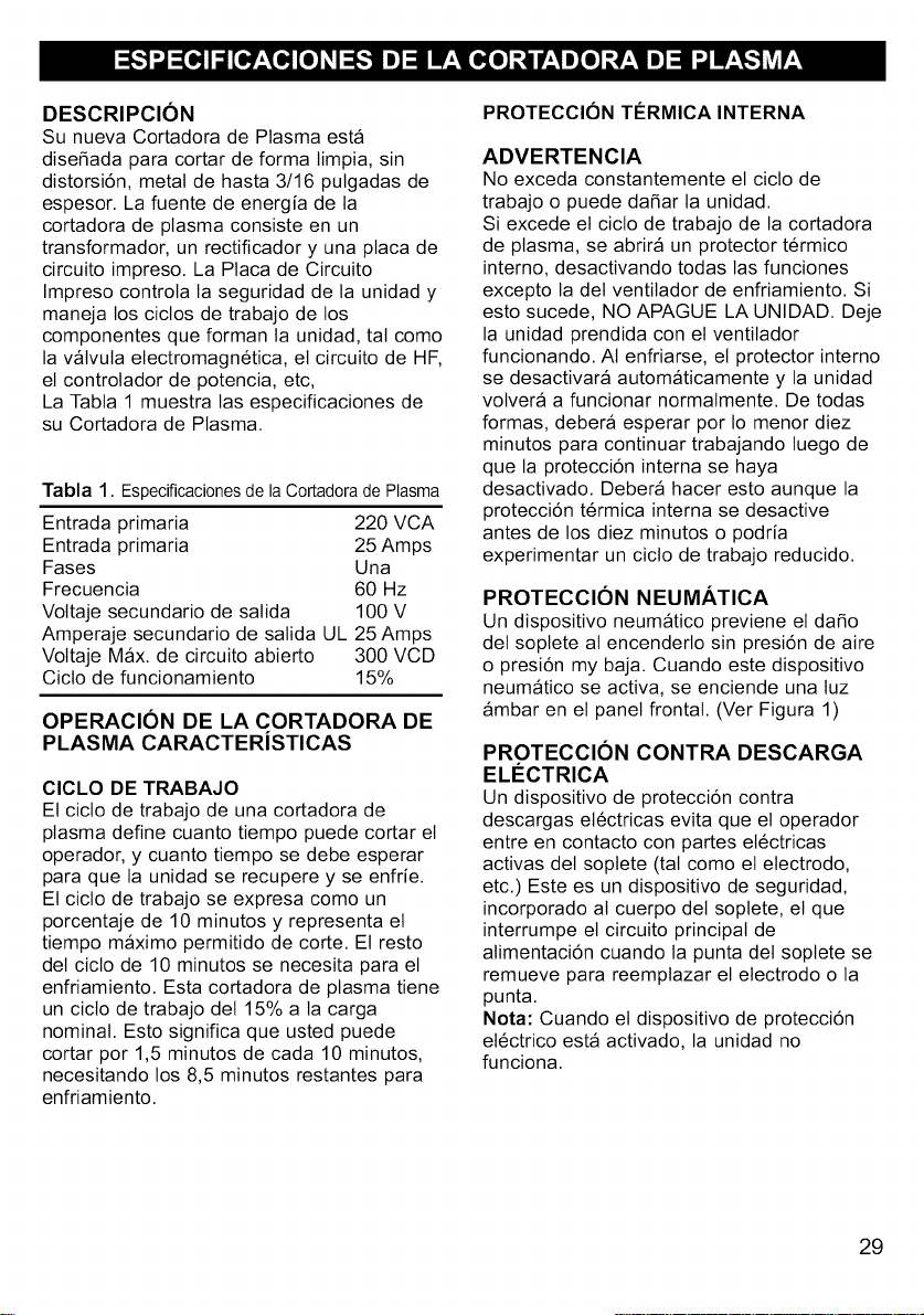
DESCRIPCION
Su nueva Cortadora de Plasma esta
disei_ada para cortar de forma limpia, sin
distorsi6n, metal de hasta 3/16 putgadas de
espesor. La fuente de energ{a de la
cortadora de plasma consiste en un
transformador, un rectificador y una ptaca de
circuito impreso. La Placa de Circuito
Impreso controla la seguridad de la unidad y
maneja los ciclos de trabajo de los
componentes que forman ta unidad, tat como
la valvula electromagn6tica, et circuito de HF,
el controlador de potencia, etc,
La Tabta 1 muestra tas especificaciones de
su Cortadora de Plasma.
Tabla 1. Especificacionesde laCortadoradePlasma
Entrada primaria 220 VCA
Entrada primaria 25 Amps
Fases Una
Frecuencia 60 Hz
Voltaje secundario de satida 100 V
Amperaje secundario de satida UL 25 Amps
Vottaje Max. de circuito abierto 300 VCD
Cicto de funcionamiento 15%
OPERACION DE LA CORTADORA DE
PLASMA CARACTERiSTICAS
ClCLO DE TRABAJO
El cicto de trabajo de una cortadora de
plasma define cuanto tiempo puede cortar el
operador, y cuanto tiempo se debe esperar
para que la unidad se recupere y se enfrie.
El cicto de trabajo se expresa como un
porcentaje de 10 minutos y representa el
tiempo maximo permitido de core. El resto
det ciclo de 10 minutos se necesita para el
enfriamiento. Esta cortadora de plasma tiene
un cicto de trabajo det 15% a ta carga
nominal. Esto significa que usted puede
cortar por 1,5 minutos de cada 10 minutos,
necesitando los 8,5 minutos restantes para
enfriamiento.
PROTECCION TI_RMICA INTERNA
ADVERTENCIA
No exceda constantemente et ciclo de
trabajo o puede daSar la unidad.
Si excede el ciclo de trabajo de la cortadora
de plasma, se abrira un protector t6rmico
interno, desactivando todas las funciones
excepto la del ventilador de enfriamiento. Si
esto sucede, NO APAGUE LA UNIDAD. Deje
la unidad prendida con el ventitador
funcionando. At enfriarse, el protector interno
se desactivara automaticamente y la unidad
volvera a funcionar normatmente. De todas
formas, debera esperar por Io menor diez
minutos para continuar trabajando tuego de
que la protecci6n interna se haya
desactivado. Debera hacer esto aunque la
protecci6n t6rmica interna se desactive
antes de los diez minutos o podria
experimentar un cicto de trabajo reducido.
PROTECCION NEUMATICA
Un dispositivo neumatico previene et daSo
del soptete at encenderlo sin presi6n de aire
o presi6n my baja. Cuando este dispositivo
neumatico se activa, se enciende una tuz
ambar en et panel frontal. (Ver Figura 1)
PROTECCION CONTRA DESCARGA
ELI_CTRICA
Un dispositivo de protecci6n contra
descargas et6ctricas evita que el operador
entre en contacto con partes et6ctricas
activas del soptete (tal como el electrodo,
etc.) Este es un dispositivo de seguddad,
incorporado at cuerpo det soptete, el que
interrumpe el circuito principal de
atimentaci6n cuando la punta del soplete se
remueve para reemptazar el electrodo o la
punta.
Nota: Cuando et dispositivo de protecci6n
electrico esta activado, la unidad no
funciona.
29
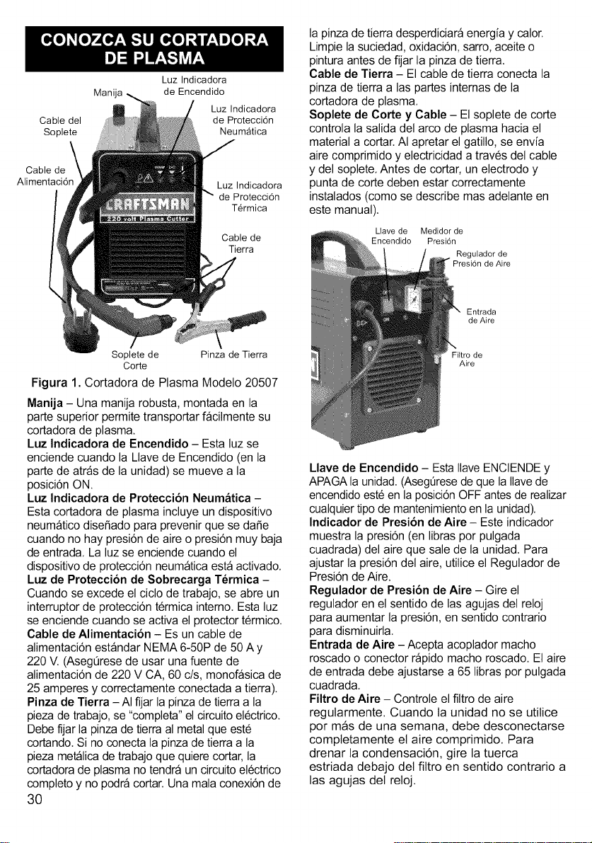
Luz Indicadora
Manija de Encendido
Luz Indicadora
Cable del de Protecci6n
Soplete Neumatica
Cable de
Alimentaci6n
Luz Indicadora
de Protecci6n
T_rmica
Cable de
Tierra
la pinza de tierra desperdiciara energia y calor.
Limpie la suciedad,oxidaci6n, sarro, aceiteo
pinturaantes de fijar la pinza de tierra.
Cable de Tierra - El cable de tierra conecta la
pinza de tierra alas partes internas de la
cortadora de plasma.
Soplete de Corte y Cable - El soplete de corte
controla la salida del arco de plasma hacia el
material a cortar.AI apretar el gatillo, se envia
aire comprimido y electricidad a traves del cable
y del soplete. Antes de cortar, un electrodo y
punta de corte deben estar correctamente
instalados (como se describe mas adelante en
este manual).
Uave de Medidor de
Encendido Presi6n
Regulador de
Presi6n de Aire
Entrada
de Aire
Soplete de Pinza de Tierra
Corte
Figura 1. Cortadora de Plasma Modelo 20507
Manija - Una manija robusta, montada en la
parte superior permite transportar facilmente su
cortadora de plasma.
Luz Indicadora de Encendido - Esta luz se
enciende cuando la Llave de Encendido (en la
parte de atras de la unidad) se mueve a la
posici6n ON.
Luz Indicadora de Protecci6n Neum_tica -
Esta cortadora de plasma incluye un dispositivo
neumatico diseSadopara prevenir que se daSe
cuando no hay presi6n de aire o presi6n muy baja
de entrada. La luz se enciende cuando el
dispositivode protecci6n neumatica esta activado.
Luz de Proteccibn de Sobrecarga T_rmica -
Cuando se excede el ciclo de trabajo, se abre un
interruptor de protecci6n termica interno. Esta luz
se enciende cuando se activa el protector termico.
Cable de Alimentaci6n - Es un cable de
alimentaci6n estandar NEMA 6-50P de 50 Ay
220 V.(AsegQresede usar una fuente de
alimentaci6n de 220 V CA, 60 c/s, monofasica de
25 amperes y correctamente conectada a tierra).
Pinza de Tierra -AI fijar la pinza de tierraa la
pieza de trabajo, se "completa" elcircuito electrico.
Debe fijar la pinza de tierraal metal que este
cortando.Si no conecta la pinza de tierraa la
pieza metalica de trabajo que quiere cortar,la
cortadorade plasma no tendra un circuitoelectrico
completoy no podra cortar. Unamala conexi6n de
3O
Filtro de
Aire
Llave de Encendido - EstaIlave ENCIENDEy
APAGAla unidad.(AsegQresede que la Ilavede
encendido est6 en la posici6n OFF antes de realizar
cualquiertipo de mantenimientoen la unidad).
Indicador de Presi6n de Aire - Este indicador
muestra la presi6n (en libras por pulgada
cuadrada) del aire que sale de la unidad. Para
ajustar la presi6n del aire, utilice el Regulador de
Presi6n de Aire.
Regulador de Presi6n de Aire - Gire el
regulador en el sentido de las agujas del reloj
para aumentar la presi6n, en sentido contrario
para disminuirla.
Entrada de Aire - Acepta acoplador macho
roscado o conector rapido macho roscado. El aire
de entrada debe ajustarse a 65 libras por pulgada
cuadrada.
Filtro de Aire - Controle el flltro de aire
regularmente. Cuando la unidad no se utilice
por mas de una semana, debe desconectarse
comptetamente el aire comprimido. Para
drenar la condensaci6n, gire la tuerca
estriada debajo del filtro en sentido contrario a
las agujas del reloj.
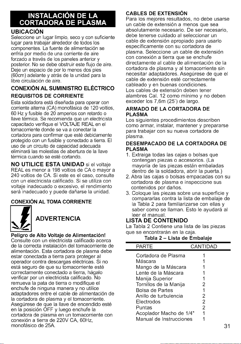
UBICACION
Seleccioneunlugarlimpio,secoyconsuficiente
lugarparatrabajaralrededordetodoslos
componentes.Lafuentedealimentaci6nse
enfriapormediodeunacorrientedeaire
forzadoatravesdelospanelesanteriory
posterior.Nosedebeobstruiresteflujodeaire.
DejeunespaciodeporIomenosdospies
(60cm)adelanteyatrasdelaunidadparala
librecirculaci6ndeaire.
CONEXIONAL SUMINISTRO ELC:CTRICO
REQUISITOS DE CORRIENTE
Esta soldadora esta disefiada para operar con
corriente alterna (CA) monofasica de 120 voltios,
60 Hz y fusible de 20 amperios con retardo o
Ilave termica. Se recomienda que un electricista
capacitado verifique el VOLTAJE REAL en el
tomacorriente donde se va a conectar la
cortadora para confirmar que este debidamente
protegido con un fusible y conectado a tierra. El
uso de un circuito de capacidad adecuada
eliminara las molestias de abertura de la Ilave
termica cuando se este cortando.
NO UTILICE ESTA UNIDAD si el voltaje
REAL es menor a 198 voltios de CA o mayor a
240 voltios de CA. Si este es el caso, consulte
con un electricista caiificado. Si se utiliza con
voltaje inadecuado o excesivo, el rendimiento
sera inadecuado y puede dafiarse la unidad.
CONEXION AL TOMA CORRIENTE
_ ADVERTENCIA
Peligro de Alto Voltaje de Alimentacibn!
Consutte con un etectricista calificado acerca
de la correcta instalaci6n det tomacorriente de
alimentaci6n. Esta cortadora de plasma debe
estar conectada a tierra para proteger at
operador contra descargas el6ctricas. Si no
esta seguro de que su tomacorriente est6
correctamente conectado a tierra, hagalo
verificar por un electricista calificado. No
remueva ta pata de tierra o modifique el
enchufe de ninguna manera y no utilice
adaptadores entre et cable de alimentaci6n de
la cortadora de plasma y et tomacorriente.
AsegQrese de que la tlave de encendido est6
en la posici6n OFF y luego enchufe la
cortadora de plasma en un tomacorriente con
conexi6n a tierra de 220V CA, 60Hz,
monofasico de 25A.
CABLES DE EXTENSION
Para los mejores resultados, no debe usarse
un cable de extensi6n a menos que sea
absolutamente necesario. De ser necesario,
debe tenerse cuidado at seleccionar un
cable de extensi6n apropiado para usarlo
especificamente con su cortadora de
plasma. Seleccione un cable de extensi6n
con conexi6n a tierra que se enchufe
directamente al cable de atimentaci6n de la
cortadora de plasma y al tomacorriente sin
necesitar adaptadores. AsegQrese de que el
cable de extensi6n est6 correctamente
cabteado yen buenas condiciones.
Los cables de extensi6n deben tener
alambres Cat. 12 como minimo y no deben
exceder los 7,6m (25') de largo.
ARMADO DE LA CORTADORA DE
PLASMA
Los siguientes procedimientos describen
como armar, instatar, mantener y prepararse
para trabajar con su nueva cortadora de
plasma.
DESEMPACADO DE LA CORTADORA DE
PLASMA
1. Extraiga todas las cajas o bolsas que
contengan piezas o accesorios. (La
mayoria de las piezas estan embaladas
dentro de la sotdadora, abrir la puerta.)
2. Abra las cajas o bolsas empacadas con su
cortadora de plasma e inspeccione sus
contenidos por dafios.
3. Cotoque las piezas sobre una superficie y
compararlas contra la tista de embataje de
la Tabta 2 para familiarizarse con elias y
saber como se Ilaman. Esto le ayudara al
leer el manual.
LISTA DE CONTENIDO
La Tabta 2 Contiene una lista de las piezas
que se encontraran en la caja.
Tabla 2 - Lista de Embalaje
PARTE CANTI DAD
Cortadora de Plasma 1
Mascara 1
Mango de la Mascara 1
Lente de la Mascara 1
Manija Superior 1
Tornitlos de la Manija 2
Bolsa de Partes 1
Anitlo de turbutencia 2
Electrodos 2
Puntas 2
Acoptador Macho de 1/4" 1
Manual de Instrucciones 1
31
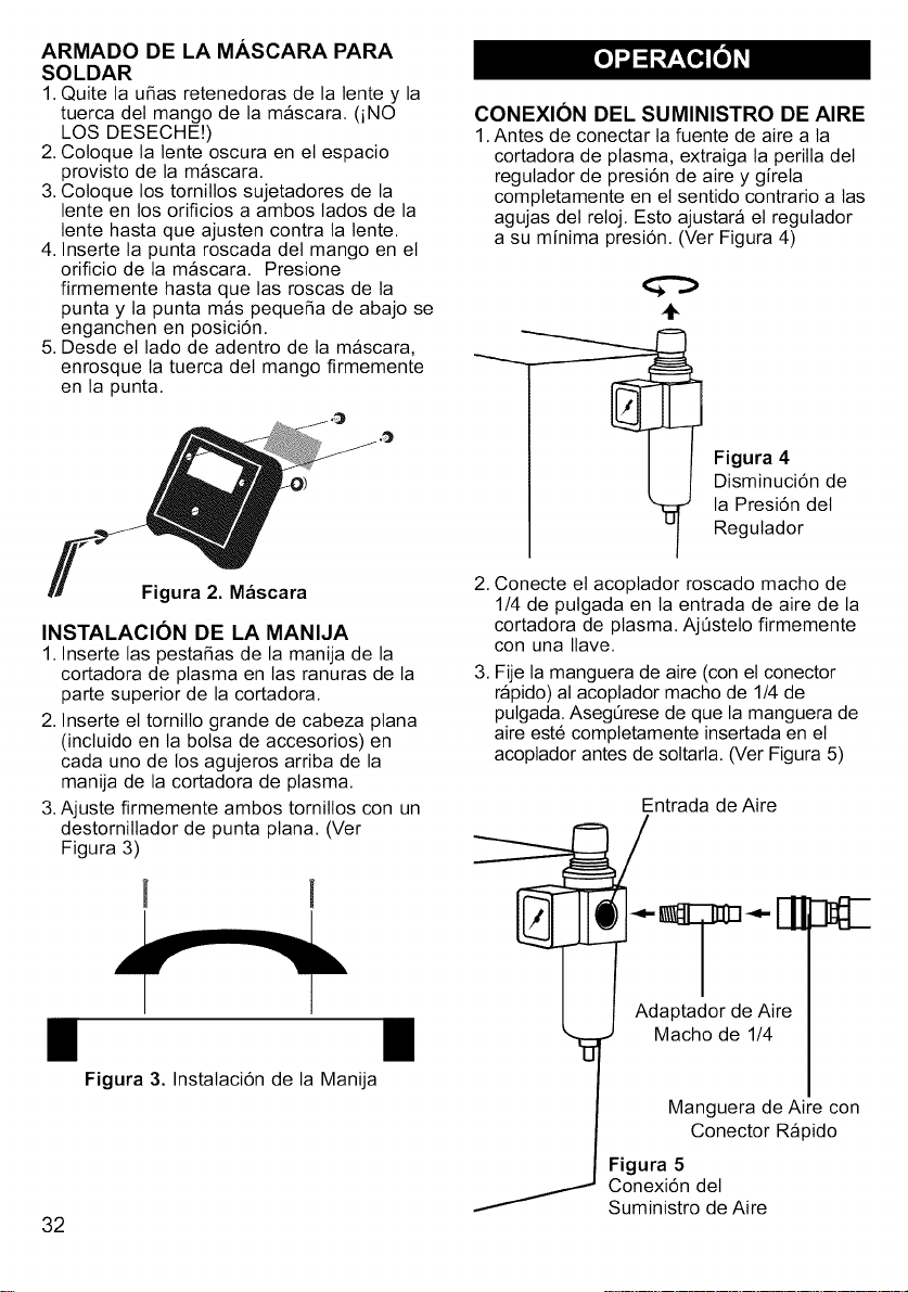
ARMADO DE LA MASCARA PARA
SOLDAR
1. Quite la u_as retenedoras de la lente y la
tuerca del mango de la mascara. (iNO
LOS DESECHE!)
2. Coloque la lente oscura en et espacio
provisto de la mascara.
3. Coloque los tornitlos sujetadores de la
lente en los orificios a ambos lados de la
lente hasta que ajusten contra ta tente.
4. Inserte la punta roscada del mango en el
orificio de la mascara. Presione
firmemente hasta que las roscas de ta
punta y la punta mas peque_a de abajo se
enganchen en posici6n.
5. Desde et lado de adentro de ta mascara,
enrosque la tuerca del mango firmemente
en la punta.
CONEXION DEL SUMINISTRO DE AIRE
1.Antes de conectar ta fuente de aire a la
cortadora de plasma, extraiga la peritta del
regutador de presi6n de aire y gireta
comptetamente en et sentido contrario a tas
agujas det retoj. Esto ajustara et regutador
a su minima presi6n. (Ver Figura 4)
÷
Figura 4
Disminuci6n de
la Presi6n del
Regutador
Figura 2. Mascara
INSTALACION DE LA MANIJA
1. Inserte las pestaSas de la manija de la
cortadora de plasma en las ranuras de la
parte superior de la cortadora.
2. Inserte el tornitlo grande de cabeza ptana
(incluido en ta bolsa de accesorios) en
cada uno de los agujeros arriba de la
manija de la cortadora de plasma.
3.Ajuste firmemente ambos tornillos con un
destomillador de punta ptana. (Ver
Figura 3)
I!
Figura 3. Instataci6n de la Manija
32
2. Conecte et acoptador roscado macho de
1/4 de putgada en la entrada de aire de la
cortadora de plasma. Aj0stelo firmemente
con una Ilave.
3. Fije la manguera de aire (con et conector
rapido) al acoplador macho de 1/4 de
pulgada. Aseg0rese de que la manguera de
aire est6 comptetamente insertada en el
acoplador antes de sottarla. (Ver Figura 5)
Entrada de Aire

4.Abralaentradadeaire.Aseg0resedeque
lapresi6ndelaentradadeaireseadepor
Iomenos90psi.(1oidealesentre90y
120psi)
5.Extraigalaperiltadelregutadordeairey
ajustelapresi6na65psigirandolaperilla
enetsentidodelasagujasdetretoj.
6.Cuandolapresi6nenetindicadordel
regutadorIteguea65psi,trabelaperiltaen
esaposici6nempujandolafirmemente.
(VerFigura6)
O
Figura 6
Ajuste de la
Presi6n del
Regutador
CONEXION DE LA PINZA DE TIERRA
A LA PIEZA DE TRABAJO
1. Quite toda la tierra, grasa, sarro,
oxidaci6n, pintura, etc. del area de la
pieza de trabajo donde conectara la pinza
de tierra.
2. La pinza de tierra debe conectarse a la
pieza de trabajo Io mas cerca posible del
area a cortar. AsegQrese de que tanto la
pinza de tierra como et cable de tierra
estaran en el camino de la linea de corte.
3.Ajuste la pinza de tierra a ta pieza de
trabajo. AsegQrese de que la pinza de
tierra est6 seguramente agarrada a la
pieza de trabajo de manera que no se
aftoje durante la operaci6n de corte.
ENCENDIENDO LA UNIDAD
1. Enchufe el cable de alimentaci6n en un
tomacorriente de 220V CC, 60Hz,
monofasico correctamente conectado a
tierra.
2. Encienda ta unidad, mediante la Ilave de
encendido principal en el panel posterior de
la cortadora de plasma. Se escuchara un
soptido por unos instantes hasta que et
sistema se cargue y se cierre la valvula de
drenaje del filtro de aire.
3.AsegQrese de que la Luz Indicadora de
Encendido se encienda en et panel frontal
de la maquina, indicando que la cortadora
de plasma esta recibiendo energia el6ctrica.
4. Mientras sostiene et soptete tejos de usted
y otras personas en el area de trabajo,
presione et gatitlo y verifique que la
presi6n indicada en et medidor sea
aproximadamente 65psi.
Nota: Esta Cortadora de Plasma tiene un
sistema interno de seguridad para evitar los
arcos accidentales. Para encender el arco
piloto, apriete el gatillo del soplete; sueltelo y
aprietelo nuevamente dentro de los 3
segundos. El arco piloto se apagara
automaticamente luego de 2-3 segundos si no
se ha comenzado a cortar. Para encender
nuevamente el arco piloto, simple repetir los
instrucciones previos. Evite el encendido
innecesario del arco piloto para evitar que se
gaste el electrodo y la punta.
PRINClPIOS DEL CORTE CON
PLASMA
El corte de plasma es una forma rapida,
limpia y sin distorsi6n, de cortar todo tipo de
metales desde livianos y aceros inoxidables
hasta aluminio, bronce y cobre.
El proceso se basa en la reacci6n quimica
del aire sujeto a temperaturas muy altas. El
aire se ioniza, dejando los atomos cargados
positivamente. En este estado ionizado, el
aire es conductor de electricidad y se
denomina "plasma".
Un arco electrico estable es creado para
alcanzar la alta temperatura necesaria para
crear plasma. AI forzar el plasma a traves de
un pico pequefio, el arco se concentra y su
temperatura se eleva a mas de 36.000 grados
Fahrenheit y se concentra en un area muy
pequefia.
AI dirigir el plasma hacia un material
conductor (conectado a la pinza de tierra de la
cortadora de plasma) el arco se transfiere al
material a traves del plasma. La alta energia
del arco funde el material. El material fundido
es simultaneamente forzado fuera del area de
corte por el flujo de aire. AI remover el metal
fundido de la linea de corte del arco de
plasma, se obtiene un corte rapido y limpio.
El arco estable se crea produciendo un
camino ionizado en el aire. Esto se Iogra
aplicando un voltaje muy alto, de alta
frecuencia, entre el electrodo y la pieza a
trabajar, causando un arco de alta frecuencia.
El arco principal se dispara ni bien la punta y
el pico se ionizan.
Aunque usted ya haya utilizado una
cortadora de plasma anteriormente, es
importante que se familiarice con su nueva
cortadora. Le recomendamos que practique
con su nueva cortadora de plasma en trozos
33

demetaldedescartededistintotipo,distintos
espesores,ydistintasposicionesdecorte.AI
reatizarestoustedaprenderacomolos
cambiosenestasvariablesafectanel
procesodecorte.
Siustednuncahautilizadounacortadora
deplasma,necesitaradesarrollarhabilidady
t6cnicadecorteapropiadas.
Eloperadorautodidactaaprende
medianteunprocesodepruebayerror.La
mejorformadeaprenderporsimismocomo
cortarconplasmaesmedianteperiodos
cortosdepracticaaintervalosregulates.
Todosloscortesdepracticadebenhacerse
sobremetaldedescarte.Nointentecortar
ning6nequipovaliosohastaqueest6
satisfechodequesuscortesdepracticason
satisfactoriosysinmayoresdefectos.
CARGA
EL_CTRICA
(-)
GAS DE ELECTRODO
_-DELSOPLETE
GAS DE
PROTECCION
PLASMA
Figura 7. Principios del Corte con Plasma
APRENDIENDO A CORTAR CON
PLASMA
Sosteniendo el Soplete
La mejor forma de sostener el soptete de
corte es de la forma que le sea mas
c6modo. El soptete puede agarrarse
c6modamente con una mano, o sostenerse
con ambas. Escoja la t6cnica que le sea
mas c6modo y que le permita controlar el
movimiento.
34
Posicionado el Soplete en la Pieza de
Trabajo
La punta det soplete de plasma debe estar
perpendicular a la pieza a cortar. Un anguto
excesivo del soptete puede causar que el
arco de plasma corte la pared det costado de
la punta daSando los componentes del
soptete. Es importante et mantener el soplete
de corte a la distancia correcta det material a
cortar. Esta distancia puede variar levemente,
dependiendo del tipo de material a cortar o de
su espesor, pero como regta general,
mantenga ta punta a aproximadamente 1/16 -
1/8 de putgada del material a cortar.
La Figura 8 muestra la posici6n correcta del
soplete.
I t
I I t
/I
Figura 8. Posicidn del Soptete
CORTAN DO
Una operaci6n de "corte" se define
generalmente como una operaci6n donde la
penetraci6n comienza en un borde existente
de la pieza de trabajo. No importa si este
borde es exterior o es un agujero hecho
previamente en la pieza de trabajo. La
operaci6n de corte requiere una t6cnica
levemente distinta que la operaci6n de
Perforaci6n (descripta en la secci6n
siguiente),
1. Coloque su dedo indice sobre el gatitlo.
2. Sostenga el soptete con el orificio de la
punta directamente sobre el borde de la
pieza de trabajo.
Nota: El arco se puede doblar at principio y
at final det corte si es queet arco debe
"estirarse" (desviarse de la linea recta,
perpendicular) para encontrar el metal. Un
arco doblado puede cortar el costado de la
punta del soptete.
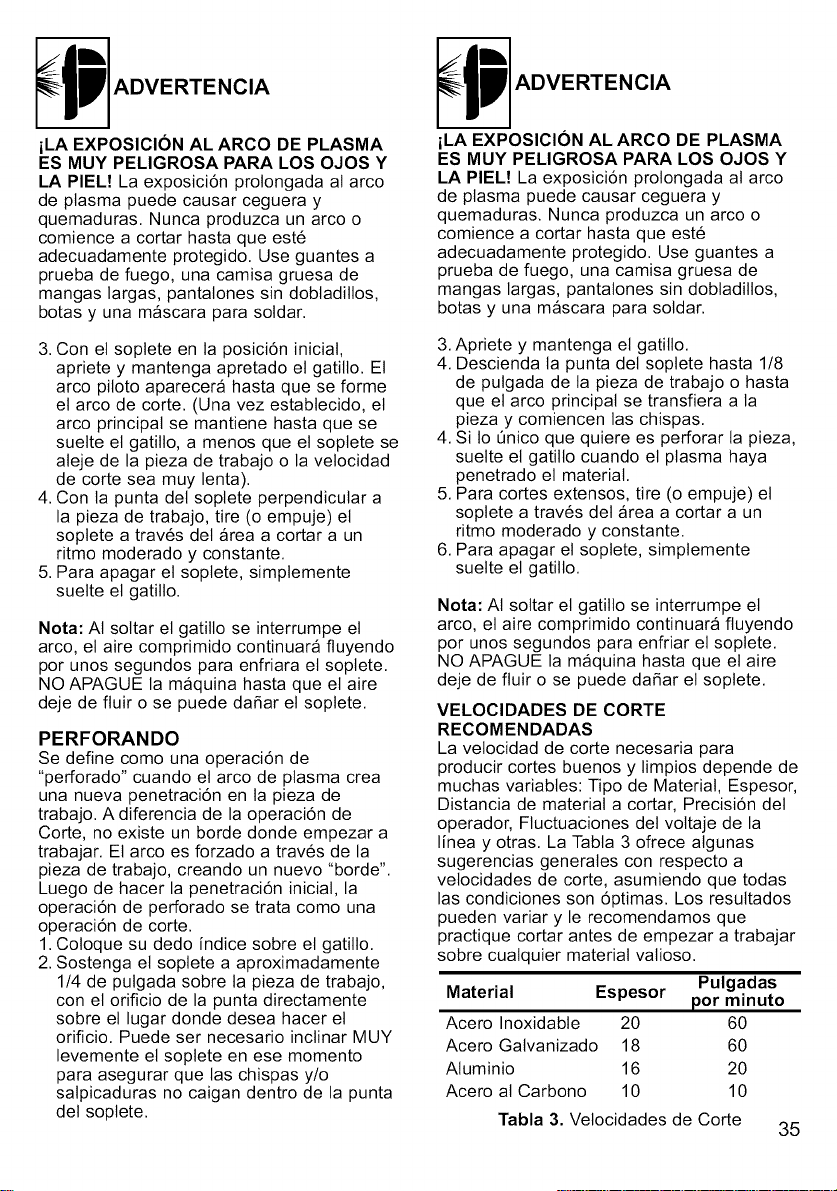
ADVERTENCIA
iLA EXPOSICION AL ARCO DE PLASMA
ES MUY PELIGROSA PARA LOS OJOS Y
LA PIEL! La exposici6n prolongada at arco
de plasma puede causar ceguera y
quemaduras. Nunca produzca un arco o
comience a cortar hasta que est6
adecuadamente protegido. Use guantes a
prueba de fuego, una camisa gruesa de
mangas largas, pantalones sin dobtaditlos,
botas y una mascara para sotdar.
3. Con el soptete en la posici6n iniciat,
apriete y mantenga apretado et gatilto. El
arco piloto aparecera hasta que se forme
et arco de corte. (Una vez estabtecido, el
arco principal se mantiene hasta que se
suelte el gatillo, a menos que et soptete se
ateje de la pieza de trabajo o la velocidad
de corte sea muy lenta).
4. Con ta punta det soplete perpendicular a
la pieza de trabajo, tire (o empuje) el
soptete a trav6s det area a cortar a un
ritmo moderado y constante.
5. Para apagar el soptete, simptemente
suette et gatillo.
Nota: AI soltar et gatillo se interrumpe el
arco, et aire comprimido continuara fluyendo
por unos segundos para enfriara el soptete.
NO APAGUE la maquina hasta que el aire
deje de fluir o se puede dafiar el soptete.
PERFORANDO
Se define como una operaci6n de
"perforado" cuando el arco de plasma crea
una nueva penetraci6n en ta pieza de
trabajo. A diferencia de la operaci6n de
Corte, no existe un borde donde empezar a
trabajar. El arco es forzado a trav6s de la
pieza de trabajo, creando un nuevo "borde".
Luego de hacer la penetraci6n iniciat, la
operaci6n de perforado se trata como una
operaci6n de corte.
1. Coloque su dedo indice sobre el gatillo.
2. Sostenga et soplete a aproximadamente
1/4 de pulgada sobre la pieza de trabajo,
con el orificio de la punta directamente
sobre el lugar donde desea hacer et
orificio. Puede ser necesario inclinar MUY
levemente el soptete en ese momento
para asegurar que las chispas y/o
salpicaduras no caigan dentro de la punta
del soptete.
ADVERTENCIA
iLA EXPOSICION AL ARCO DE PLASMA
ES MUY PELIGROSA PARA LOS OJOS Y
LA PIEL! La exposici6n prolongada at arco
de plasma puede causar ceguera y
quemaduras. Nunca produzca un arco o
comience a cortar hasta que est6
adecuadamente protegido. Use guantes a
prueba de fuego, una camisa gruesa de
mangas largas, pantalones sin dobtadillos,
botas y una mascara para soldar.
3.Apriete y mantenga el gatilto.
4. Descienda la punta det soptete hasta 1/8
de putgada de la pieza de trabajo o hasta
que el arco principal se transfiera a la
pieza y comiencen las chispas.
4. Si to Onico que quiere es perforar ta pieza,
suette el gatilto cuando el plasma haya
penetrado el material.
5. Para cortes extensos, tire (o empuje) el
soptete a trav6s det area a cortar a un
ritmo moderado y constante.
6. Para apagar et soptete, simptemente
suelte el gatilto.
Nota: AI soltar et gatilto se interrumpe et
arco, et aire comprimido continuara fluyendo
por unos segundos para enfriar et soptete.
NO APAGUE la maquina hasta que el aire
deje de fluir o se puede dafiar el soptete.
VELOCIDADES DE CORTE
RECOMENDADAS
La velocidad de corte necesaria para
producir cortes buenos y limpios depende de
muchas variables: Tipo de Material, Espesor,
Distancia de material a cortar, Precisi6n del
operador, Fluctuaciones del voltaje de la
linea y otras. La Tabta 3 ofrece algunas
sugerencias generates con respecto a
vetocidades de corte, asumiendo que todas
las condiciones son 6ptimas. Los resultados
pueden variar y le recomendamos que
practique cortar antes de empezar a trabajar
sobre cuatquier material vatioso.
Pulgadas
Material Espesor por minuto
Acero Inoxidable 20 60
Acero Gatvanizado 18 60
Atuminio 16 20
Acero at Carbono 10 10
Tabla 3. Velocidades de Corte
35
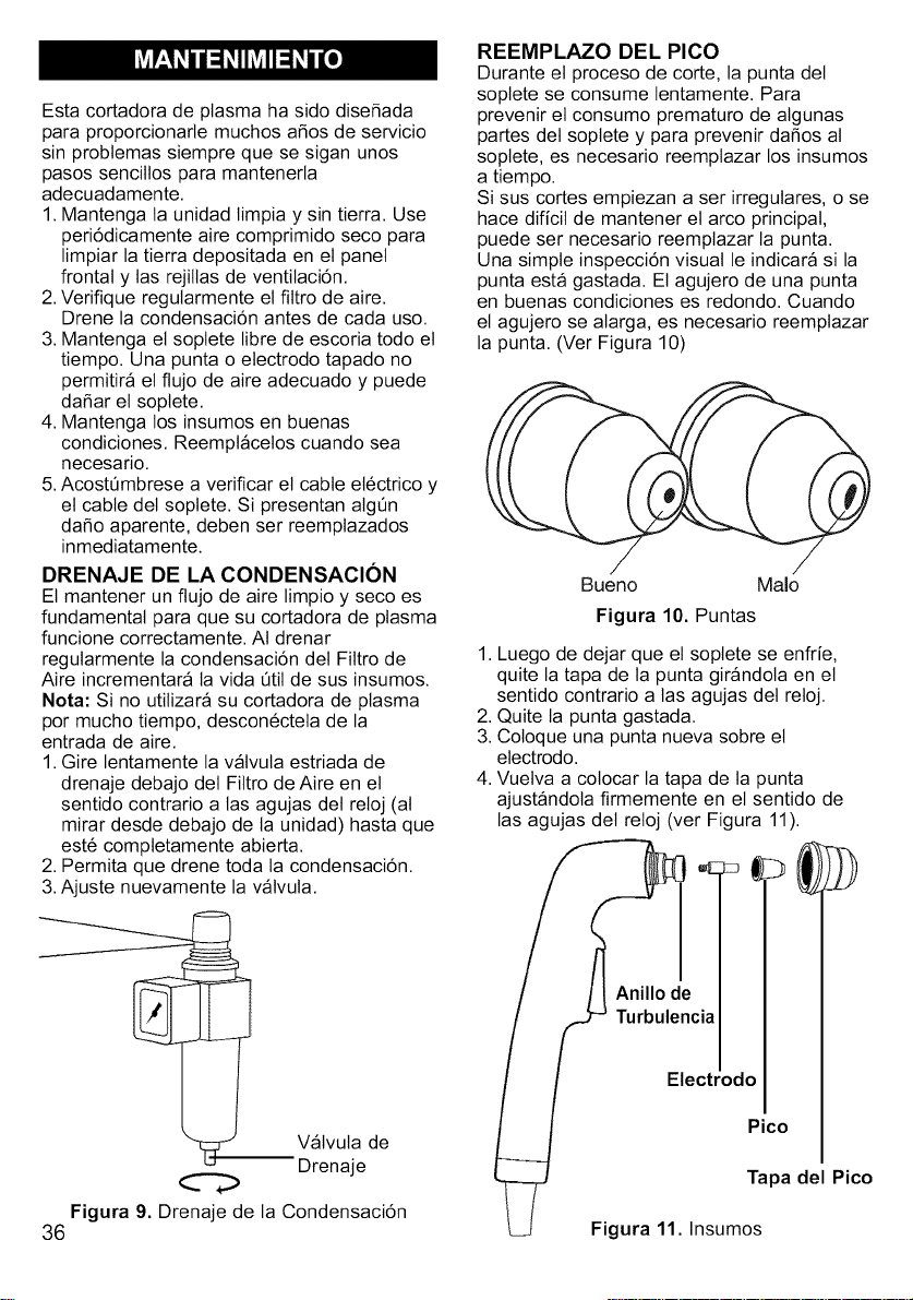
Esta cortadora de plasma ha sido dise_ada
para proporcionarle muchos a_os de servicio
sin probtemas siempre que se sigan unos
pasos senciltos para mantenerla
adecuadamente.
1. Mantenga la unidad limpia y sin tierra. Use
peri6dicamente aire comprimido seco para
limpiar la tierra depositada en et panel
frontal y las rejillas de ventilaci6n.
2. Verifique regularmente el filtro de aire.
Drene la condensaci6n antes de cada uso.
3. Mantenga el soplete libre de escoria todo el
tiempo. Una punta o electrodo tapado no
permitira el flujo de aire adecuado y puede
da_ar el soptete.
4. Mantenga los insumos en buenas
condiciones. Reemptacelos cuando sea
necesario.
5.Acost6mbrese a verificar el cable el6ctrico y
et cable del soplete. Si presentan atgOn
da_o aparente, deben ser reemplazados
inmediatamente.
DRENAJE DE LA CONDENSACION
El mantener un flujo de aire limpio y seco es
fundamental para que su cortadora de plasma
funcione correctamente. AI drenar
regularmente la condensaci6n det Filtro de
Aire incrementara la vida 6til de sus insumos.
Nora: Si no utilizara su cortadora de plasma
por mucho tiempo, descon6ctela de la
entrada de aire.
1. Gire lentamente la valvuta estriada de
drenaje debajo det Filtro de Aire en el
sentido contrario alas agujas del reloj (al
mirar desde debajo de la unidad) hasta que
est6 completamente abierta.
2. Permita que drene toda ta condensaci6n.
3.Ajuste nuevamente la vatvula.
Vatvuta de
Drenaje
REEMPLAZO DEL PICO
Durante el proceso de corte, la punta det
soptete se consume lentamente. Para
prevenir et consumo prematuro de algunas
partes del soptete y para prevenir da_os al
soptete, es necesario reemptazar los insumos
a tiempo.
Si sus cortes empiezan a ser irregutares, o se
hace dificit de mantener et arco principal,
puede set necesario reemplazar la punta.
Una simple inspecci6n visual le indicara si la
punta esta gastada. El agujero de una punta
en buenas condiciones es redondo. Cuando
el agujero se atarga, es necesario reemplazar
la punta. (Ver Figura 10)
Bueno Malo
Figura 10. Puntas
1. Luego de dejar que et soptete se enfrie,
quite la tapa de la punta girandola en el
sentido contrario a las agujas del reloj.
2. Quite ta punta gastada.
3. Cotoque una punta nueva sobre et
electrodo.
4. Vuelva a colocar la tapa de la punta
ajustandola firmemente en et sentido de
las agujas det reloj (ver Figura 11).
Anillo de
Turbulencia
Electrodo
Pico
Tapa del Pico
Figura 9. Drenaje de la Condensaci6n
36 Figura 11. Insumos
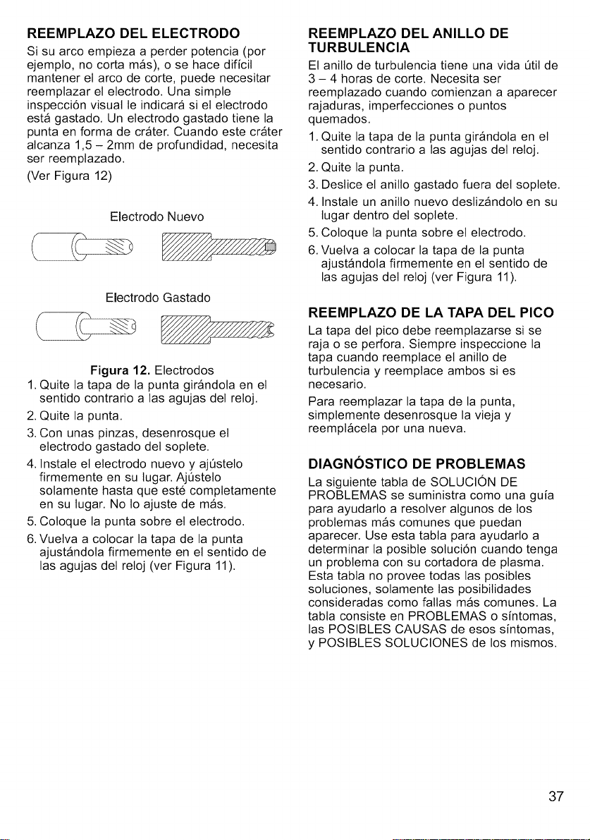
REEMPLAZO DEL ELECTRODO
Si su arco empieza a perder potencia (por
ejempto, no corta mas), o se hace dificil
mantener el arco de corte, puede necesitar
reemptazar el etectrodo. Una simple
inspecci6n visual le indicara si el electrodo
esta gastado. Un electrodo gastado tiene la
punta en forma de crater. Cuando este crater
alcanza 1,5 - 2mm de profundidad, necesita
ser reemplazado.
(Ver Figura 12)
Electrodo Nuevo
Electrodo Gastado
Figura 12. Electrodos
1. Quite la tapa de la punta girandola en el
sentido contrario a las agujas del reloj.
2. Quite la punta.
3. Con unas pinzas, desenrosque el
etectrodo gastado det soptete.
4. Instate et electrodo nuevo y ajOstelo
firmemente en su tugar. AjOstelo
solamente hasta que est6 comptetamente
en su tugar. No 1oajuste de mas.
5. Coloque la punta sobre et electrodo.
6. Vuetva a colocar la tapa de la punta
ajustandola firmemente en el sentido de
las agujas del reloj (ver Figura 11).
REEMPLAZO DEL ANILLO DE
TURBULENCIA
El anillo de turbulencia tiene una vida _til de
3 - 4 horas de core. Necesita ser
reemplazado cuando comienzan a aparecer
rajaduras, imperfecciones o puntos
quemados.
1. Quite la tapa de la punta girandola en el
sentido contrario alas agujas del reloj.
2. Quite la punta.
3. Destice et anitlo gastado fuera del soptete.
4. Instate un anillo nuevo destizandolo en su
lugar dentro det soptete.
5. Coloque la punta sobre et electrodo.
6. Vuelva a colocar la tapa de la punta
ajustandola firmemente en el sentido de
las agujas del reloj (ver Figura 11).
REEMPLAZO DE LA TAPA DEL PICO
La tapa det pico debe reemptazarse si se
raja o se perfora. Siempre inspeccione la
tapa cuando reemptace et anillo de
turbulencia y reemptace ambos si es
necesario.
Para reemplazar la tapa de la punta,
simptemente desenrosque la vieja y
reemptacela por una nueva.
DIAGNOSTICO DE PROBLEMAS
La siguiente tabla de SOLUCION DE
PROBLEMAS se suministra como una guia
para ayudarlo a resolver algunos de los
problemas mas comunes que puedan
aparecer. Use esta tabta para ayudarlo a
determinar la posibte soluci6n cuando tenga
un probtema con su cortadora de plasma.
Esta tabta no provee todas las posibles
soluciones, solamente las posibitidades
consideradas como fatlas mas comunes. La
tabla consiste en PROBLEMAS o sintomas,
las POSlBLES CAUSAS de esos sintomas,
y POSlBLES SOLUClONES de los mismos.
37
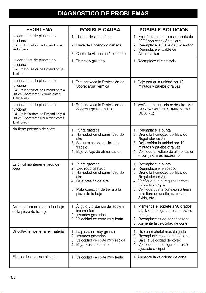
PROBLEMA
La cortadora de plasma no
funciona
(LaLuzIndicadorade Encendidono
se ilumina)
La cortadora de plasma no
funciona
(La Luz Indicadora de Encendido se
ilumina)
La cortadora de plasma no
funciona
(La Luz Indicadora de Encendido y la
Luz de Sobrecarga T_rmica est_n
iluminadas)
La cortadora de plasma no
funciona
(La Luz Indicadora de Encendido y la
Luz de Sobrecarga Neum_tica est_n
iluminadas)
No tiene potencia de corte
Es diffcil mantener el arco de 1.
corte 2.
3.
4.
5.
Acumulacidn de material debajo 1.
de la pieza de trabajo
2.
3.
Dificultad en penetrar el material 1.
2.
3.
4.
El arco desaparece al cortar 1.
POSIBLE CAUSA
1. Unidad desenchufada
2. Llave de Encendido da_ada
3. Cable de Alimentaci6n da_ado
1. Electrodo gastado
1. Est_ activada la Protecci6n de
Sobrecarga Termica
1. Est_ activada la Protecci6n de
Sobrecarga Neumatica
1. Punta gastada
2. Humedad en el suministro de
aire
3. Se ha excedido el ciclo de
trabajo
4. Bajo voltaje de alimentaci6n
Punta gastada
Electrodo gastado
Humedad en el suministro de
aire
Baja presi6n de aire
Mala conexi6n de tierra a la
pieza de trabajo
,&ngulo y distancia del soplete
incorrectos
Insumos gastados
Velocidad de corte muy lenta
La pieza es muy gruesa
Insumos gastados
Velocidad de corte muy rapida
Baja presi6n de aire
POSIBLE SOLUCION
1. EnchOfela en un tomacorriente de
220V con conexidn a tierra
2. Reemplace la Llave de Encendido
3. Reemplace el Cable de
Alimentaci6n
1. Reemplace el electrodo
1. Deje enfriar la unidad por 10
minutos y pruebe otra vez
1.Verifique el suministro de aire (Ver
CONEXION DEL SUMINISTRO
DE AIRE)
1. Reemplace la punta
2. Drene la humedad del filtro de
Regulador de Aire
3. Deje enfriar la unidad por 10
minutos y pruebe otra vez
4. Verifique el voltaje de alimentaci6n
- corrijalo si es necesario
1. Reemplace la punta
2. Reemplace el electrodo
3. Drene la humedad del filtro de
Regulador de Aire
4. Verifique que el regulador est6
ajustado a 65psi
5. Verifique que la conexidn a tierra
est6 libre de aceite, suciedad,
6xido, etc.
1. Mantenga el soplete a 90 grados
y a 1/8 de pulgada de la pieza de
trabajo
2. Reemplacelos de ser necesario
3. Aumente la velocidad de corte
1. Use un material mas delgado
2. Reemplacelos de ser necesario
3. Baje la velocidad de corte
4. Verifique que el regulador est6
ajustado a 65psi
Velocidad de corte muy lenta 1.Aumente la velocidad de corte
38
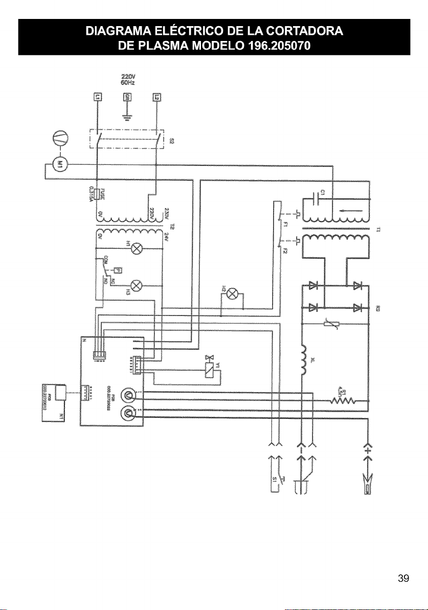
2_V
39

4O
No. Cbdigo
01 WE20507-21045004
02 WE20507-21035004
03 WE20507-21030011
04 WE20507-21000020
05 WE20507-21050003
06 WE20507-21040011
07 WE20507-22910007
08 WE20507-22900002
09 WE20507-22910037
10 WE20507-22910060
11 WE20507-21005012
12 WE20507-21030002
13 WE20507-22400093
14 WE20507-10900008
15 WE20507-23015001
16 WE20507-21050013
17 WE20507-21890020
18 WE20507-22900005
19 WE20507-22315007
20 WE20507-21035005
21 WE20507-21025011
22 WE20507-33820071
23 WE20507-21690120
24 WE20507-22720022
25 WE20507-22720012
26 WE20507-44140055
27 WE20507-21020044
28 WE20507-30490047
29 WE20507-22905072
30 WE20507-22910068
31 WE20507-22910074
32 WE20507-20220120
33 WE20507-21020017
34 WE20507-33705374
35 WE20507-21600030
36 WE20507-44135009
37 WE20507-21610001
38 WE20507-21030003
39 WE20507-21020021
40 WE20507-21020025
41 WE20507-21605023
42 WE20507-21025028
43 WE20507-33720122
44 WE20507-21605007
45 WE20507-21000002
46 WE20507-21035002
47 WE20507-21025029
48 WE20507-22200025
49 WE20507-22220016
50 WE20507-22220021
51 WE20507-21605036
52 WE20507-21020002
53 WE20507-21605023
54 WE20507-23010049
55 WE20507-21690286
56 WE20507-22610004
57 WE20507-22610011
58 WE20507-22110005
59 WE20507-43210028
60 WE20507-21605032
61 WE20507-21025008
62 WE20507-33700200
63 WE20507-21025004
64 WE20507-22800021
65 WE20507-21030004
66 WE20507-21015018
67 WE20507-22305003
68 WE20507-22315008
69 WE20507-21690287
70 WE20507-21020026
71 WE20507-21020032
72 WE20507-44130066
73 WE20507-21905007
74 WE20507-21905002
Descripcibn
Tuerca hexagonal para soporte de sopleta
Arandela dentada
Arandela Plana
Tomillo para soporte de soplete y resistor
Arandela dorada de 5ram para soporte de soplete
Tornillo dorado para soporte de soplete
Casquillo cbnico de 1/8" 1!8" M
M
V&lvula electromagn_tica de gas 4W 24V 60Hz 118"FF
Conector 1/8" F-F"T"
Conector r_pido macho 8mm - 1!8"
Tomillo para rectificador y cable de tierra
Arandela Plana del Rectificador
Rectificador de 30A 1600V
Manguera de gas 6X5
Conector para soplete con tuerca
Arandela dorada de 13ram para soporte de sopleta
Soporte del conector del sopleta
Interrupter de presibn de aire 4.4 BAR
Condensador de 30MF 450V
Arandela de Trabapara Condensador
Tuerca hexagonal del condensador
Disipador del rectificador
Soporte de placa de circuito impreso
Place de circuito imprese
Placa de circuito impreso de seguddad para el gatillo del soplete
Transformador auxiliar 110/220/230V 60Hz 25X30
Tomillo autorroscante para transformador auxiliar
Espaciador para reductor
Reductor con manbmetro
Conector %" G - ¼ NTP
Conector r&pido macho ¼" NTP
Cable de alimentacibn con enchufe 3xAWG12 M2.5 220V 50A
Tomillo Autorroscante para Gabineta
Panel Protector
Manija Pl_stica
Filtro 40X50 AI
Pata de pl&stico
Arandela Plana
Tornillo autorroscanta 4.2X22
Tomillo autorroscante para filtro 4.8X13
Arandela del panel frontal para soplete
Tuerca hexagonal con pestaSa para soporte de sopleta
Panel Divisorio
Abrazadera de goma para cable
Tomillo para reductor .
Arandela dentada para reductor y cable de tierra
Tuerca hexagonal con pestaSa para disipador
Llave Selectora de Voltaje
Porta fusible PTT/35 6 3A 250V
Fusible de vidrio 5X20 T 0 315A 250V
Abrazadera de cable para panel posterior
Tomillo Autorroscante para rejilla de ventilacibn
Arandela de goma del panel divisorio
Soplete de plasma
Rejilla de ventilacibn del panel frontal
Lampara piloto verde 24V L-600
Lampara piloto anaranjada 12V L-500
Pinza de Tierra de 120A
Cable de tierra con pinza
Abrazadera del cable de tierra
Tuerca hexagonal del resistor
Panel Inferior
13erea hexagonal del cable de tierra
Ventilador complete 120X120X38 230V 50160HZ
Arandela plana del resistor
Perno de montaje del resistor
Resistor de 4,5 Hems 50 L=165
Condensador de 40MF 450V
Rejilla pl&stica de ventilaci6n posterior
Tomillo Autorroscante para rejilla de ventilacibn posterior
Tornillo autorroscante para manija
Transformador 220V 60HZ 60X70CU
Vidrio oscuro 75)(98
M&scara de pl&stico 75X98
Cantidad
2
4
12
4
2
1
1
1
1
1
4
4
1
1
1
4
1
1
1
1
1
18
1
1
1
8
8
8
3
1
2
1
4
2
6
2
1
1
1
1
3
1
1
1
1
2
1
1
1
4
1
5
1
4
1
1
1
1
4
2
1
1
t
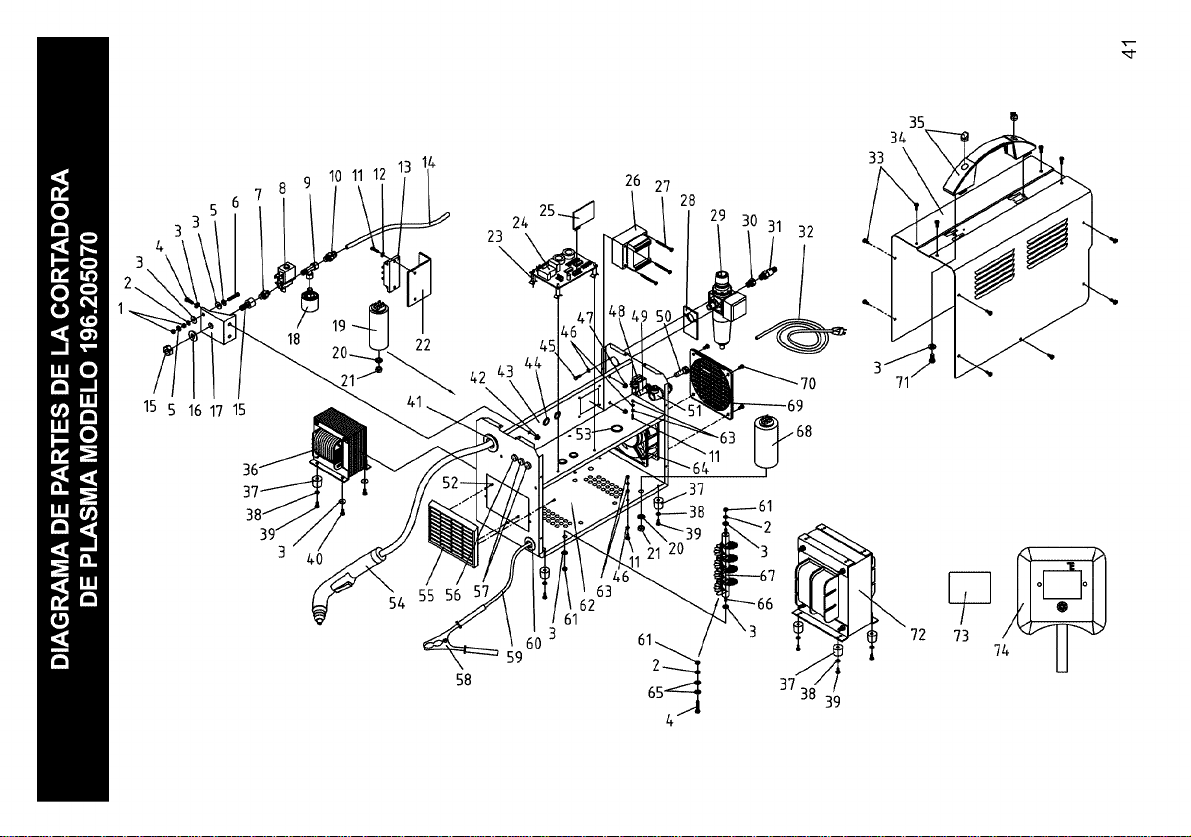
15 5 16 17 15
10 11 12
24
23
\
26 27
28
32
35
3a
71j
58
62
61
3
)
59
65
37
39
72
73 7

1
l
No. C6digo Descripci6n
01 WE20507-23015128 Manija del soplete de plasma
02 WE20507-23015101 Gatillo del soplete
03 WE20507-23015129 Cabeza del soplete de plasma
04 WE20507-23015117 Electrodo para soplete de plasma
05 WE20507-23015027 Anillo de turbulencia
06 WE20507-23015118 Punta D.0.8
07 WE20507-23015119 Tapa de la punta
Cantidad
1
1
1
1
1
1
1
42

Your Home
For repair - in your home - of all major brand appliances,
lawn and garden equipment, or heating and cooling systems,
no matter who made it, no matter who sold it!
For the replacement parts, accessories and
owner's manuals that you need to do-it-yourself.
For Sears professional installation of home appliances
and items like garage door openers and water heaters.
1-800-4-MY-HOME ® Anytime, day or night
(1-800-469-4663) (U.S.A. and Canada)
www.sears.com www.sears.ca
Our Home
1-800-827-6655 (U.S.A.)
Para pedir serviciode reparaci6n
a domicilio,y para ordenar piezas:
1-888-SU-HOGAR sM
(1-888-784-6427)
SEARS
For repair of carry-in products like vacuums, lawn equipment,
and electronics, call or go on-line for the nearest
Sears Parts and Repair Center.
1-800-488-1222 Anytime, day or night (U.S.A. only)
www.sears.com
To purchase a protection agreement (U.S.A.)
or maintenance agreement (Canada) on a product serviced by Sears:
1-800-361-6665 (Canada)
Au Canada pour service en frangais:
1-800-LE-FOYERMc
(1-800-533-6937)
www.sears.ca
(c)Sears, Roebuck and Co.
(R)Registered Trademark / TMTrademark / SMService Mark of Sears, Roebuck and Co.
_) Marca Registrada / TMMarca de F&brica / SMMarca de Servicio de Sears, Roebuck and Co.
MCMarque de commerce / MDMarque depos6e de Sears, Roebuck and Co.