
1
LA600WH WIRED /
WIRELESS DOOR CHIME
To register this product, visit: www.nutone.com
THIS PACKAGE INCLUDES:
n Wired / Wireless Door Chime with MP3 upload capability
n Decorative White Chime Cover
n USB Cable
n Mounting Hardware
n Pushbutton Diode (required for wired installation)
Door chime comes with eight pre-loaded sounds. Prior to installation,
upload desired MP3 sound files.
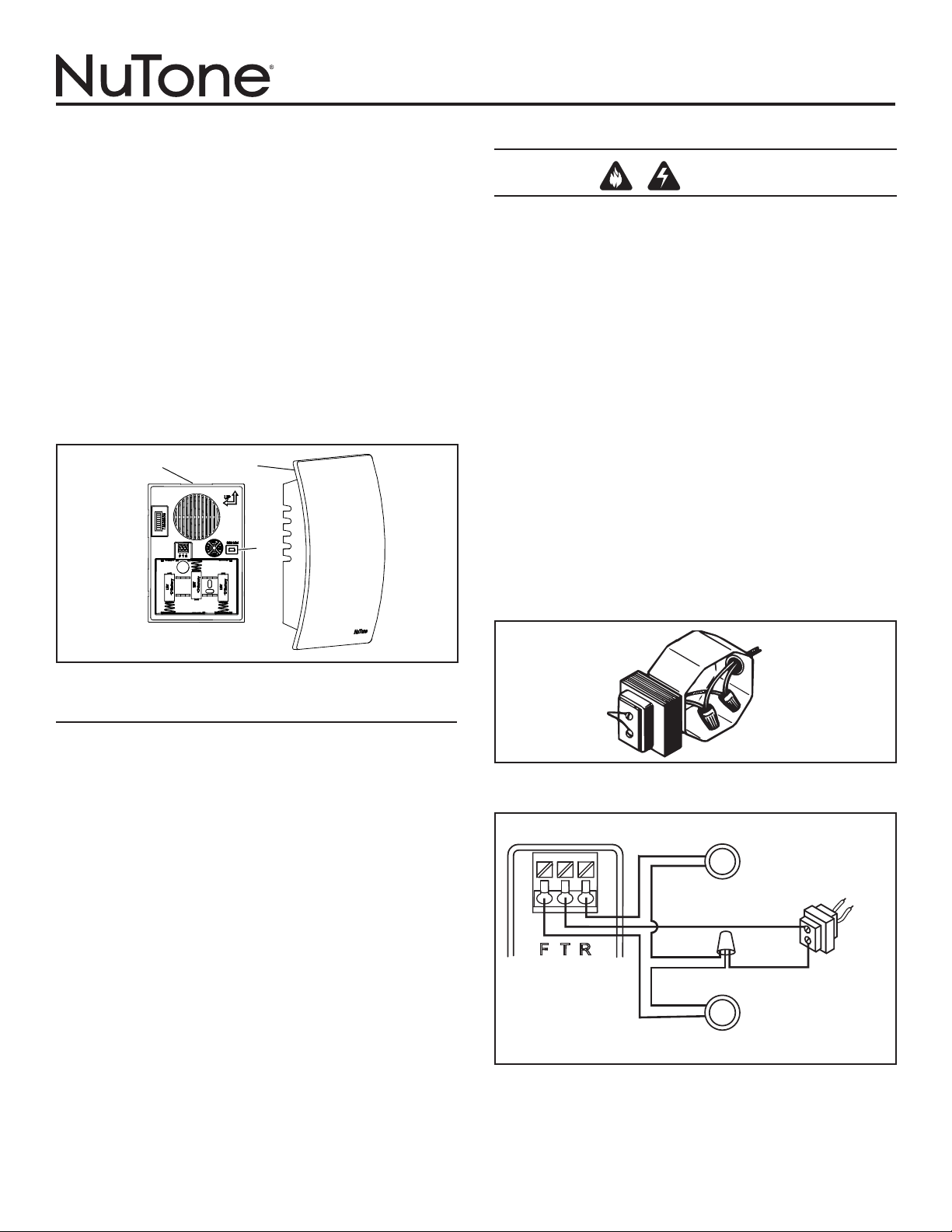
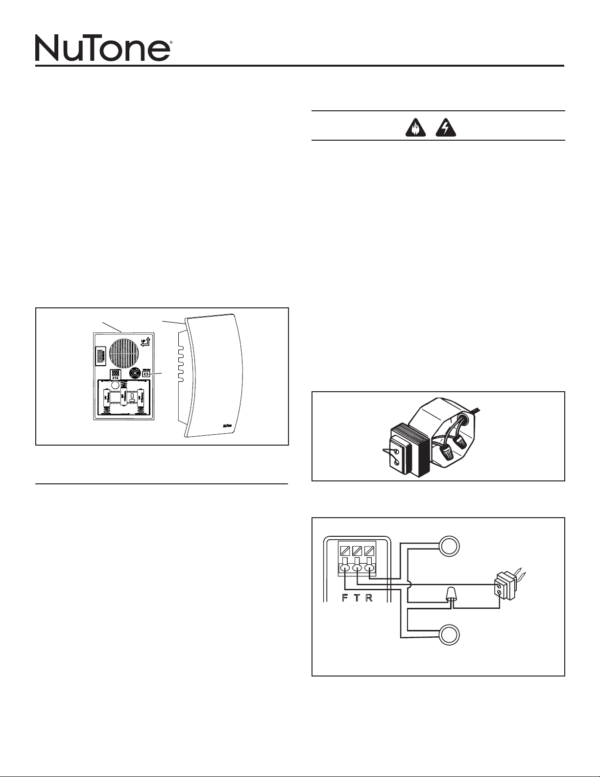
1. Remove chime cover (B) from chime base (A). You may need to
insert a finger into the large hole on the back of the chime base.
(Figure 1)
UPLOAD MP3 TUNES
1. Insert a USB Mini cable end into the doorbell mechanism USB jack
(C). (Figure 1)
2. Insert the remaining larger USB cable end into a USB port on your
computer.
3. On your WINDOWS computer,
• Select “Start” in the bottom corner of your Desktop.
• Select “My Computer”
• Select the new device detected. (The drive “D:”, “E:”, etc. will vary
from computer to computer).
• Select the device.
• You will now see a window that contains several mp3 files. These
are the tunes that are pre-installed on your doorbell mechanism.
• Search your computer for other mp3 songs that you wish to play
on your doorbell mechanism when activated. Note: Files must be
in mp3 format.
• Once you have located those files, simply “COPY” the file and
“PASTE” it into the folder that contains the pre-installed doorbell
files.
• Confirm that the transfered files are complete.
4. Remove USB cable and proceed to one of the following sections.
INSTALLATION & OPERATING INSTRUCTIONS
READ AND SAVE THESE INSTRUCTIONS
WIRES
TO
CHIME
SUPPLY
WIRE
FIGURE 2
FIGURE 3
WIRING DIAGRAM
SCREWLESS
WIRING CONNECTOR
ON CHIME BASE
REAR DOOR PUSHBUTTON
120 VAC
WIRING
TRANSFORMER
FRONT DOOR
PUSHBUTTON WITH
DIODE INSTALLED
A
B
C
FIGURE 1
NEW WIRED CHIME INSTALLATION
WARNING
•
TO REDUCE THE RISK OF FIRE, ELECTRIC SHOCK, OR INJURY TO
PERSONS, OBSERVE THE FOLLOWING:
•
Use this unit only in the manner intended by the manufacturer. If you have
questions, contact the manufacturer at the address or telephone number
listed in the warranty.
•
Before servicing or cleaning unit, switch power off at service panel and
lock the service disconnecting means to prevent power from being
switched on accidentally. When the service disconnecting means cannot
be locked, securely fasten a prominent warning device, such as a tag,
to the service panel.
•
Installation work and electrical wiring must be done by a qualified
person(s) in accordance with all applicable codes and standards, including
fire-rated construction codes and standards.
•
When cutting or drilling into wall or ceiling, do not damage electrical wiring
and other hidden utilities.
•
Use NuTone
®
16 volt transformer with a minimum rating of 10 VA (purchase
separately).
•
When stapling wires to studs or joists, do not allow staples to cut through
wire insulation.
1. Mount the transformer to a junction box (attic location is not
recommended) or circuit breaker box.
2. Connect house power leads to transformer leads: black to black,
white to white, ground to green. (Figure 2)
3. Route 2-conductor 18-22 gauge wire from the transformer screw termi-
nals and from the pushbutton terminals to the chime location. (Figure 3)
4. Label all wires at chime location in the following manner:
“F” – Front Pushbutton Wire
“T” – Transformer Wire
“R” – Rear Pushbutton Wire (if installed)
2
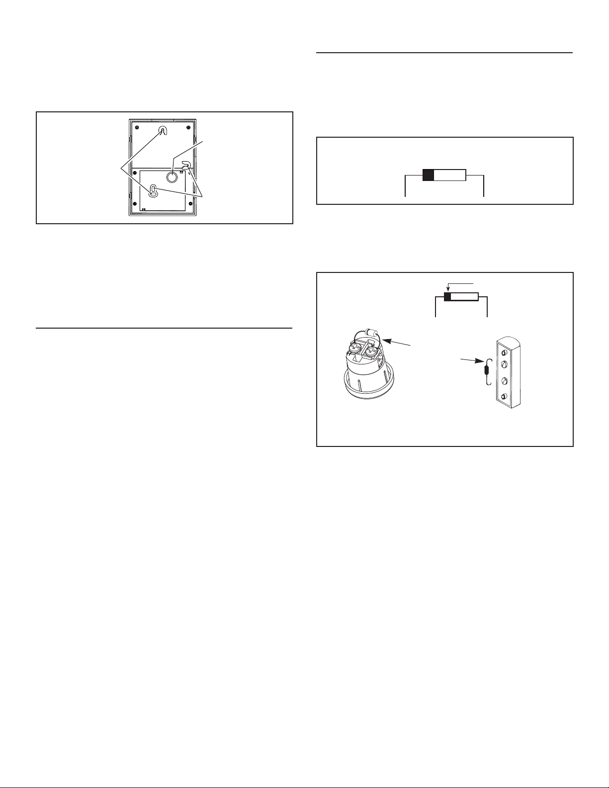
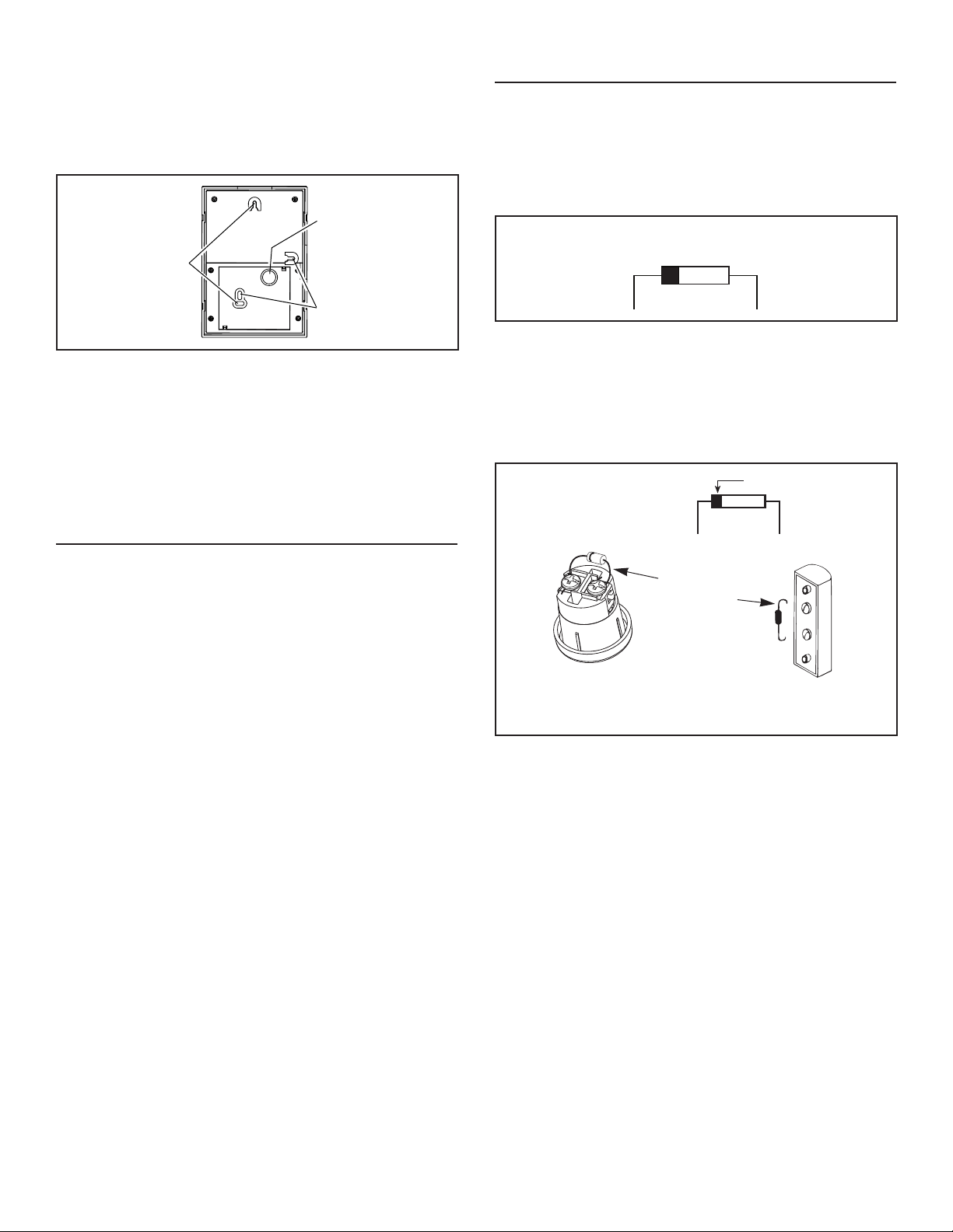
5. The chime can be installed vertically or horizontally. Determine your
preferred orientation. Locate the arrows on the front of the chime
base. Make sure one of the arrows is pointing up. (Figure 4)
6. Bring wires through the circular wire hole (D) in chime base. (Figure
4)
7. Mount chime base to wall using screws provided. Always use 2
screws for wall mounting. (Figure 4)
8. Connect wires to the screwless wiring connector as follows: Wire “F”
to connector terminal “F”, wire “T” to connector terminal “T” and wire
“R” to connector terminal “R” if installed. (Figure 3)
9. Proceed to section titled: “INSTALL WIRED PUSHBUTTON”.
EXISTING WIRED CHIME INSTALLATION
TURN OFF POWER AT SERVICE ENTRANCE.
1. Verify a 16-volt transformer with a minimum rating of 10 VA is in-
stalled.
2. Remove existing chime cover.
3. Label all wires in the following manner:
“F” – Front Pushbutton Wire
“T” – Transformer Wire
“R” – Rear Pushbutton Wire (if installed)
4. Disconnect all wires from existing chime base and remove from wall.
5. Follow Steps 6 through 9 under section titled: “NEW WIRED
INSTALLATION.”
FIGURE 5
DIODE FOR FRONT DOOR
PUSHBUTTON
FIGURE 6
WRAP
DIODE WIRE
AROUND
EACH
TERMINAL
SCREW
AND CLIP
EXCESS
WIRES
DIODE
SILVER BAND
RECESSED FRONT
DOOR PUSHBUTTON
SURFACE-MOUNT FRONT
DOOR PUSHBUTTON
TRANSFORMER
WIRE
FRONT
WIRE
INSTALL WIRED PUSHBUTTONS
Power to transformer should be disconnected during pushbutton
installation.
A diode must be added to the front door pushbutton so that power
will be supplied continuously to the chime.
Do not install a diode on the rear door pushbutton.
1. Locate the envelope containing the front door pushbutton diode.
(Figure 5)
2. If using an existing pushbutton(s), remove existing pushbutton(s)
from wall. If installing new pushbutton(s), refer to installation
instructions provided with pushbutton(s).
3. Gently loosen pushbutton terminal screws and install diode from Step
1 on front door pushbutton only. (Figure 5) Wrap diode wires around
terminals and clip excess wires. (Figure 6)
4. Connect the chime wire to the front door pushbutton terminal closest to
the silver band on the diode. Connect the transformer wire to the other
terminal.
5. Restore power to transformer.
6.
Press the pushbutton and listen for the chime to sound. If chime does
not operate, disconnect power to transformer and reverse orientation of
diode. Restore power to transformer.
7. After confirming chime operates, follow steps under section titled
“Manage Chime Notification” to select a tune, set tune duration, and
set volume.
8. Install pushbutton(s) on wall.
NOTE: To prevent shorting on metal siding, place a piece of
insulating tape on the siding surface near the diode.
NOTE: Lighted pushbutton brightness will be reduced by 30%-40%.
This is normal and will increase the life of the bulb.
9. Place cover (B) over chime base (A) and press down to install.
A “click” will confirm that it is securely attached. (Figure 1)
10. Proceed to section titled: “Manage Chime Notifications”.
D
FIGURE 4
VERTICAL
MOUNTING
HOLES
HORIZONTAL
MOUNTING
HOLES
3
WIRELESS CHIME INSTALLATION
Unobstructed wireless operating range: Up to 100 feet.
NOTE: Wireless pushbutton sold separately. Refer to installation
instructions included with wireless pushbutton.
Keep batteries out of the reach of children.
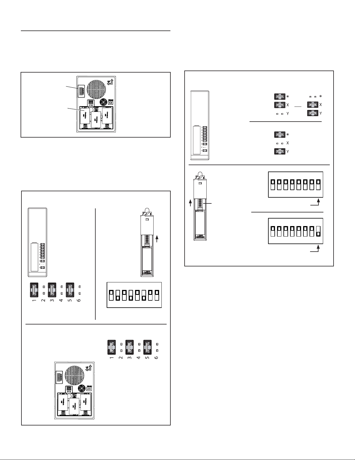
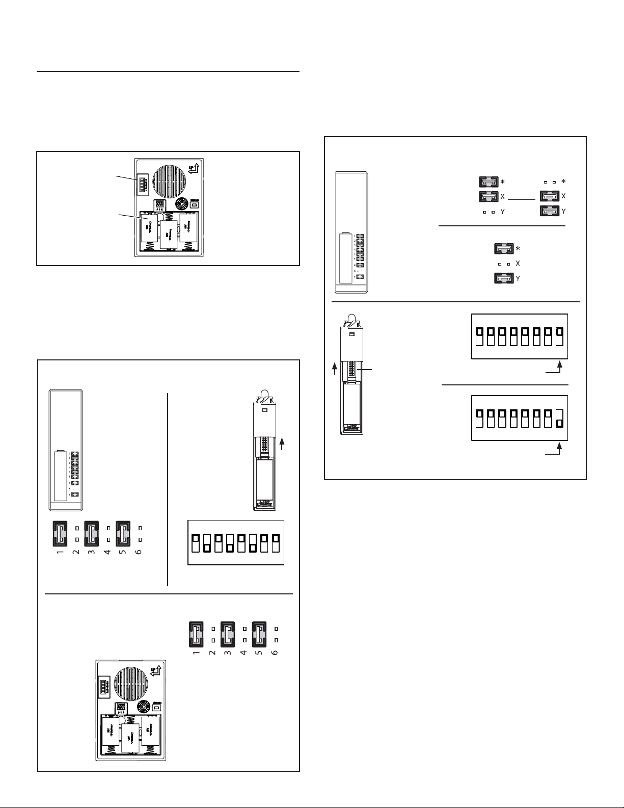
1. Insert three alkaline “D” batteries (not included) (E) in battery com-
partment. Make sure batteries are oriented properly. (Figure 7)
2. Obtain wireless pushbutton(s) (sold separately) and install battery
per wireless pushbutton(s) instructions.
3. Press pushbutton(s) to confirm the chime mechanism and
pushbutton(s) work properly. If the chime does not sound:
a. Confirm the code settings in the chime mechanism and wireless
pushbutton(s) are the same. Jumpers (F) installed on the num-
bered contacts on the chime mechanism must match the switches
or jumpers in the wireless pushbutton(s). (Figures 7 & 8)
E
F
FIGURE 7
1 2 3 4 5 6
ON
7 8
SWITCHES 2, 4, 6
IN OFF POSITION
JUMPERS REMOVED (OFF)
FROM 2, 4, 6
b. Verify proper installation of batteries in chime mechanism and
pushbutton(s).
c. Check condition of batteries in chime mechanism and
pushbutton(s). Replace if required.
4. After confirming chime operates, follow steps under section titled
“Manage Chime Notification” before proceeding to Step 5.
5. If more than one pushbutton is being installed, refer to Figure 9 to
assign doors.
6. Install the wireless pushbutton(s) at the desired door(s). Refer to
installation instructions provided with wireless pushbutton(s).
7. Place chime mechanism in desired location. Confirm operation by
pressing pushbutton(s). If the chime does not sound:
a. The chime or pushbutton(s) are mounted on or near stucco or
metal studs, the transmitter range may be reduced. Use wood
shims to raise chime or pushbutton(s) 1/4” to 1/2” from surface.
b. Concrete floors and walls may also reduce transmitter range.
Move chime away from concrete floor or wall.
c. Install chime mechanism closer to wireless pushbutton(s).
8. Remove batteries from mechanism.
9. Mount chime base to wall using screws provided (see Step 8 in “New
Wired Chime Installation” section).
10. After mounting chime base to wall, install batteries.
11. Place cover (B) over chime base (A) and press down to install.
A “click” will confirm that it is securely attached. (Figure 1).
12. Proceed to section titled: “Manage Chime Notification”.
PUSH
BUTTON
BATTERY
{
CODE SET
JUMPERS 1-6
CODE SET
SWITCHES 1-6
{
WIRELESS PUSHBUTTON - EXAMPLE CODE SETTING
(Pushbutton will have jumpers or switches)
WIRELESS CHIME - EXAMPLE CODE SETTING
JUMPERS REMOVED (OFF)
FROM 2, 4, 6
WIRELESS
CHIME
JUMPERS
{
FIGURE 8
1 8
JUMPERS
{
WIRELESS PUSHBUTTON - ASSIGN DOORS
(Wireless pushbutton will have jumpers or switches)
PUSH
BUTTON
BATTERY
{
DOOR SET
JUMPERS
*,X,Y
DOOR SET
SWITCH 8
1 2 3 4 5 6
ON
7 8
1 2 3 4 5 6
ON
7 8
SWITCH 8 ON
SWITCH 8 OFF
FIGURE 9
OR
FRONT
DOOR
REAR
DOOR
FRONT
DOOR
REAR
DOOR
1 8
4
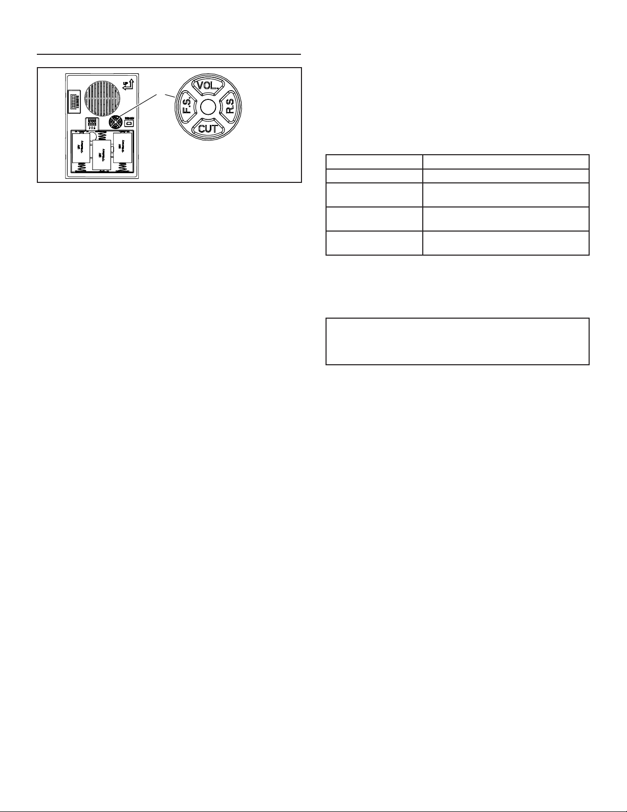
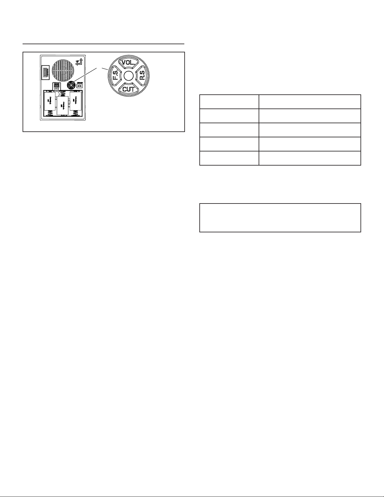
Length of Tune Played Frequency of Flashing LED
5 sec. Flashes once every second for 20 seconds.
10 sec.
Flashes 2 times, delays for 2 seconds, then
repeats for 20 seconds.
20 sec.
Flashes 3 times, delays for 2 seconds, then
repeats for 20 seconds.
Full Song Played
LED is illuminated continuously for 20
seconds.
Regulatory Information
The user is cautioned that changes or modications not expressly
approved by the party responsible for regulatory compliance could
void the user’s authority to operate this equipment.
This device complies with Part 15 of the FCC rules.
This device complies with RSS-210 of the Industrial Canada Rule.
Operation is subject to the following two conditions:
1. This device may not cause harmful interference, and
2. This device must accept any interference received, including
interference that may cause undesired operation.
Adjust volume
While the tune is playing, press “VOL” button (Figure 10) one or more times
to cycle through three volume levels.
MANAGE CHIME NOTIFICATION
Select a Tune
The four button switch and indicator LED (G) on the chime are used to
select the desired tunes for the chime. (Figure 10)
1. Make sure that the chime is powered (batteries or wiring).
2. Press “FS” button (Figure 10) one or more times to cycle through the
tunes for the front door pushbutton. Do not press “FS” button after
desired tune plays.
3. If rear door pushbutton is installed, press “RS” button (Figure 10) one
or more times to cycle through the tunes for the rear door pushbutton.
Do not press “RS” button after desired tune plays.
G
Note: Press buttons with light
fingertip pressure. Do not use
tool to press buttons.
FIGURE 10
Set Tune Duration
1. Once the tune is selected, the time the tune plays can be
adjusted to one of four durations:
• Press the “CUT” button (Figure 10) one or more times to select
the play time desired (5, 10, 20 seconds or the full song).
• The desired play time is indicated by the LED indicator as
outlined in the table below:

5
TROUBLESHOOTING GUIDE
SYMPTOM SOLUTION
Rings once, then stops (wired chime).
1. Change diode orientation.
Ghost ringing (wired chime).
1. Open chime cover and change code with jumper(s).
Ghost ringing (wireless chime).
1. Open chime cover and change code with jumper(s).
2. Also change wireless pushbutton to match new code.
Poor sound quality
1. Quality of MP3 may be poor.
2. Decrease chime volume to reduce distortion.
No sound (wired chime).
1. Wire chime correctly.
2. Make sure transformer is the proper size.
3. Make sure diode orientation is correct. Press and hold pushbutton for 5
seconds and continue to hold, if the door chime rings after 5 seconds then
the diode is connected backwards. If chime doesn’t ring, check items 1 and 2.
No sound (wireless chime). 1. Make sure pushbutton battery orientation is correct.
2. Make sure pushbutton and chime frequency code match.
3. Make sure pushbutton is within range.
4. Make sure music was downloaded properly.
a. Copy paste vs. drag and drop:
i. Both should work, but copy paste is recommended. The more files,
the longer the download may take.
b. File format must be .mp3
c. Only works with Windows PC. Will not work with a Mac.

6
WARRANTY
99528432E
Limited Warranty
Warranty Period and Exclusions: Broan (the “Company”) warrants to the original consumer purchaser of its product (“you”) that the product (the “Prod-
uct”) will be free from material defects in the Product or its workmanship for a period of one (1) year from the date of original purchase.
The limited warranty period for any replacement parts provided by the Company and for any Products repaired or replaced under this limited warranty
shall be the remainder of the original warranty period.
This warranty does not cover speed controls, fluorescent lamp starters, tubes, halogen and incandescent bulbs, fuses, filters, ducts, roof caps, wall
caps and other accessories for ducting that may be purchased separately and installed with the Product. This warranty also does not cover (a) normal
maintenance and service, (b) normal wear and tear, (c) any Products or parts which have been subject to misuse, abuse, abnormal usage, negligence,
accident, improper or insufficient maintenance, storage or repair (other than repair by the Company), (d) damage caused by faulty installation, or instal-
lation or use contrary to recommendations or instructions, (e) any Product that has been moved from its original point of installation, (f) damage caused
by environmental or natural elements, (g) damage in transit, (h) natural wear of finish, (i) Products in commercial or nonresidential use, or (j) damage
caused by fire, flood or other act of God. This warranty covers only Products sold to original consumers in the United States by the Company or U.S.
distributors authorized by the Company.
This warranty supersedes all prior warranties and is not transferable from the original consumer purchaser.
No Other Warranties: This Limited Warranty contains the Company’s sole obligation and your sole remedy for defective products. The foregoing war-
ranties are exclusive and in lieu of any other warranties, express or implied. THE COMPANY DISCLAIMS AND EXCLUDES ALL OTHER EXPRESS
WARRANTIES, AND DISCLAIMS AND EXCLUDES ALL WARRANTIES IMPLIED BY LAW, INCLUDING WITHOUT LIMITATION THOSE OF MER-
CHANTABILITY AND FITNESS FOR A PARTICULAR PURPOSE. To the extent that applicable law prohibits the exclusion of implied warranties, the
duration of any applicable implied warranty is limited to the period specified for the express warranty above. Some states do not allow limitations on
how long an implied warranty lasts, so the above limitation may not apply to you. Any oral or written description of the Product is for the sole purpose of
identifying it and shall not be construed as an express warranty.
Whenever possible, each provision of this Limited Warranty shall be interpreted in such manner as to be effective and valid under applicable law, but if
any provision is held to be prohibited or invalid, such provision shall be ineffective only to the extent of such prohibition or invalidity, without invalidating
the remainder of such provision or the other remaining provisions of the Limited Warranty.
Remedy: During the applicable limited warranty period, the Company will, at its option, provide replacement parts for, or repair or replace, without
charge, any Product or part thereof, to the extent the Company finds it to be covered by and in breach of this limited warranty under normal use and
service. The Company will ship the repaired or replaced Product or replacement parts to you at no charge. You are responsible for all costs for removal,
reinstallation and shipping, insurance or other freight charges incurred in the shipment of the Product or part to the Company. If you must send the
Product or part to the Company, as instructed by the Company, you must properly pack the Product or part—the Company is not responsible for dam-
age in transit. The Company reserves the right to utilize reconditioned, refurbished, repaired or remanufactured Products or parts in the warranty repair
or replacement process. Such Products and parts will be comparable in function and performance to an original Product or part and warranted for the
remainder of the original warranty period.
Exclusion of Damages: THE COMPANY’S OBLIGATION TO PROVIDE REPLACEMENT PARTS, OR REPAIR OR REPLACE, AT THE COMPANY’S
OPTION, SHALL BE YOUR SOLE AND EXCLUSIVE REMEDY UNDER THIS LIMITED WARRANTY AND THE COMPANY’S SOLE AND EXCLUSIVE
OBLIGATION. THE COMPANY SHALL NOT BE LIABLE FOR INCIDENTAL, INDIRECT, CONSEQUENTIAL OR SPECIAL DAMAGES ARISING OUT
OF OR IN CONNECTION WITH THE PRODUCT, ITS USE OR PERFORMANCE.
Some states do not allow the exclusion or limitation of incidental or consequential damages, so the above limitation or exclusion may not apply to you.
This warranty gives you specific legal rights, and you may also have other rights, which vary from state to state.
This warranty covers only replacement or repair of defective Products or parts thereof at the Company’s main facility and does not include the cost of
field service travel and living expenses.
Any assistance the Company provides to or procures for you outside the terms, limitations or exclusions of this limited warranty will not constitute a
waiver of such terms, limitations or exclusions, nor will such assistance extend or revive the warranty.
The Company will not reimburse you for any expenses incurred by you in repairing or replacing any defective Product, except for those incurred with the
Company’s prior written permission.
How to Obtain Warranty Service: To qualify for warranty service, you must (a) notify the Company at the address or telephone number stated below
within seven (7) days of discovering the covered defect, (b) give the model number and part identification and (c) describe the nature of any defect in the
Product or part. At the time of requesting warranty service, you must present evidence of the original purchase date. If you cannot provide a copy of the
original written limited warranty, then the terms of the Company’s most current written limited warranty for your particular product will control. The most
current limited written warranties for the Company’s products can be found at www.broan.com .
Broan 926 West State Street, Hartford, WI 53027 www.broan.com 800-637-1453
7
TIMBRE PARA PUERTA
LA600WH CABLEADO /
INALÁMBRICO
Para registrar este producto, visite: www.nutone.com
ESTE PAQUETE CONTIENE:
n Timbre para puerta cableado/inalámbrico con capacidad de carga
por MP3
n Cubierta decorativa del timbre en color blanco
n Cable USB
n Herraje de montaje
n Diodo de botón (requerido para la instalación cableada)
El timbre para puerta viene con ocho sonidos previamente cargados. Antes de
la instalación, suba los archivos MP3 con los sonidos deseados.
1. Quite la cubierta del timbre (B) de la base del timbre (A). Tal vez necesite
insertar un dedo en el orificio grande al reverso de la base del timbre.
(Figura 1)
SUBA MELODÍAS EN MP3
1. Inserte un extremo del cable miniatura de USB en la clavija USB del
mecanismo del timbre (C). (Figura 1)
2. Inserte el extremo del cable USB más grande en un puerto USB de su
computadora.
3. En su computadora WINDOWS:
• Seleccione “Inicio” en la esquina inferior de su escritorio.
• Seleccione “Mi computadora”.
• Seleccione el nuevo dispositivo detectado (la unidad “D:”, “E:” etc.,
varía de una computadora a otra).
• Seleccione el dispositivo.
• Ahora verá una ventana que contiene varios archivos mp3. Son las
melodías instaladas previamente en el mecanismo de su timbre.
• Busque en su computadora otras canciones mp3 que desee
reproducir en el mecanismo de su puerta cuando se active.
Nota: Los archivos deben estar en formato mp3.
• Una vez que haya localizado esos archivos, simplemente “COPIE”
el archivo y “PÉGUELO” en la carpeta que contiene los archivos del
timbre previamente instalados.
• Confirme que los archivos transferidos estén completos.
4. Retire el cable USB y proceda a una de las siguientes secciones.
INSTRUCCIONES DE INSTALACIÓN Y OPERACIÓN
LEA Y CONSERVE ESTAS INSTRUCCIONES
CABLES AL
TIMBRE
CABLE DE
ALIMENTACIÓN
FIGURA 2
FIGURA 3
DIAGRAMA DE CABLEADO
CONECTOR DE
CABLEADO SIN TORNILLOS
EN LA BASE DEL TIMBRE
BOTÓN DE LA PUERTA
TRASERA
CABLEADO
DE 120 VCA
TRANSFORMADOR
BOTÓN DE LA PUERTA
DELANTERA CON EL
DIODO INSTALADO
A
B
C
FIGURA 1
INSTALACIÓN DE UN TIMBRE
CABLEADO NUEVO
ADVERTENCIA
•
PARA REDUCIR EL RIESGO DE INCENDIOS, DESCARGAS ELÉCTRICAS
O LESIONES PERSONALES, SIGA LAS SIGUIENTES PRECAUCIONES:
•
Use la unidad solo de la manera indicada por el fabricante. Si tiene preguntas,
comuníquese con el fabricante a la dirección o al número telefónico que se
incluye en la garantía.
•
Antes de dar servicio a la unidad o de limpiarla, interrumpa el suministro
eléctrico en el panel de servicio y bloquee los medios de desconexión del
servicio para evitar que la electricidad se reanude accidentalmente. Cuando no
sea posible bloquear los medios de desconexión del servicio, fije firmemente
una señal de advertencia (como una etiqueta) en un lugar visible del panel
de servicio.
•
Una o más personas calificadas deben realizar el trabajo de instalación
y el cableado eléctrico, de acuerdo con todos los códigos y normas
correspondientes, incluidos los códigos y normas de construcción específicos
de protección contra incendios.
•
Al cortar o perforar a través de la pared o del cielo raso, tenga cuidado de no
dañar el cableado eléctrico ni otros servicios ocultos.
•
Utilice un transformador NuTone
®
de 16 voltios con una capacidad nominal
mínima de 10 VA (se compra por separado).
•
Cuando engrape los cables a los montantes o a las vigas, no permita que las
grapas perforen el aislamiento de los cables.
1. Monte el transformador a una caja de conexiones (no se recomienda una
ubicación en un desván) o caja de interruptores de circuitos.
2. Conecte los cables de electricidad de la casa a los cables del
transformador de esta manera: negro con negro, blanco con blanco y
verde con tierra. (Figura 2)
3. Encamine el cable calibre 18-22 de 2 conductores desde los terminales de
tornillo del transformador y de los terminales de los botones al sitio del timbre.
(Figura 3)
4. Etiquete todos los cables en la ubicación del timbre de la siguiente manera:
“F” – Cable para el botón delantero
“T” – Cable del transformador
“R” – Cable para el botón trasero (si está instalado)
8
5. El timbre se puede instalar de manera vertical u horizontal. Determine su
orientación preferida. Encuentre las flechas en la parte delantera de la
base del timbre. Asegúrese de que una de las flechas apunte hacia arriba.
(Figura 4)
6. Pase los cables por el orificio circular (D) en la base del timbre. (Figura 4)
7. Monte la base del timbre a la pared utilizando los tornillos suministrados.
Siempre use 2 tornillos para el montaje en la pared. (Figura 4)
8. Conecte los cables al conector de cableado sin tornillos de la siguiente
manera: cable “F” al terminal de conector “F”, cable “T” al terminal de
conector “T” y cable “R” al terminal de conector “R” si está instalado
(Figura 3)
9. Continúe con la sección titulada: “INSTALE EL BOTÓN CABLEADO”.
INSTALACIÓN DE UN TIMBRE
CABLEADO EXISTENTE
DESCONECTE LA ENERGÍA ELÉCTRICA EN LA ENTRADA DE SERVICIO.
1. Veriquequesetengainstaladountransformadorde16voltiosconuna
capacidad nominal mínima de 10 VA.
2. Retire la cubierta del timbre existente.
3. Etiquetetodosloscablesdelasiguientemanera:
“F” – Cable para el botón delantero
“T” – Cable del transformador
“R” – Cable para el botón trasero (si está instalado)
4. Desconecte todos los cables de la base del timbre existente y retire
de la pared.
5. Siga los pasos 6 a 9 de la sección titulada: “INSTALACIÓN CABLEADA
NUEVA”.
FIGURA 5
DIODO PARA EL BOTÓN
DE LA PUERTA DELANTERA
FIGURA 6
DIODO
BANDA COLOR PLATA
BOTÓN EMPOTRADO
PARA PUERTADELANTERA
BOTÓN DE MONTAJE
EN SUPERFICIE PARA
PUERTA DELANTERA
CABLE DEL
TRANSFORMADOR
CABLE
DELANTERO
ENVUELVA
EL CABLE
DEL DIODO
ALREDEDOR DE
CADA TORNILLO
DE TERMINAL
Y CORTE EL
EXCESO DE
CABLE
INSTALE LOS BOTONES CABLEADOS
Mientras se instale el botón, se debe desconectar la electricidad que va
al transformador.
Debe agregarse un diodo en el botón de la puerta delantera, de tal manera
que se suministre electricidad al timbre de manera continua.
NO INSTALE UN DIODO EN EL BOTÓN DE LA PUERTA TRASERA.
1. Encuentre el sobre que contiene el diodo del botón de la puerta
delantera. (Figura 5)
2. Si utiliza botones existentes, retire los botones existentes de la pared.
Si instala botones nuevos, consulte las instrucciones de instalación
incluidas con los botones.
3. Afloje suavemente los tornillos del terminal del botón e instale el diodo
del paso 1, únicamente en el botón de la puerta delantera. (Figura 5)
Envuelva los cables del diodo alrededor de los terminales y corte el
exceso de cable. (Figura 6)
4. Conecte el cable del timbre al terminal del botón de la puerta delantera más
cercano a la banda color plata en el diodo. Conecte el cable del transformador
al otro terminal.
5. Restaure la electricidad al transformador.
6. Presione el botón y escuche que suene el timbre. Si el timbre no funciona,
desconecte la electricidad al transformador e invierta la orientación del diodo.
Restaure la electricidad al transformador.
7. Después de confirmar que funcione el timbre, siga los pasos de la sección
titulada “Control de notificaciones del timbre” para seleccionar una melodía,
ajustar la duración de la melodía y ajustar el volumen.
8. Instale los botones en la pared.
NOTA: Para prevenir un corto en la chapa metálica, coloque un trozo de cinta
aislante en la superficie de la chapa cerca del diodo.
NOTA: El brillo del botón iluminado se reducirá en un 30 a 40%. Esto es
normal y aumentará la vida de la bombilla.
9. Coloque la cubierta (B) sobre la base del timbre (A) y presione hacia abajo
para instalarla. Un “clic” confirmará que está fija con firmeza. (Figura 1)
10. Continúe con la sección titulada: “Control de notificaciones del timbre”
D
FIGURA 4
ORIFICIOS
PARA MONTAJE
VERTICAL
ORIFICIOS
PARA MONTAJE
HORIZONTAL
9
INSTALACIÓN DEL TIMBRE
INALÁMBRICO
Alcance de operación inalámbrica sin obstrucciones: Hasta 100 pies (30 m).
NOTA: El botón inalámbrico se vende por separado. Consulte las
instrucciones de instalación incluidas con el botón inalámbrico.
MANTENGA LAS PILAS FUERA DEL ALCANCE DE LOS NIÑOS.
1. Inserte tres pilas alcalinas tamaño “D” (no incluidas) (E) en el
compartimiento de las pilas. Asegúrese de que estén orientadas
correctamente. (Figura 7)
2. Consiga los botones inalámbricos (se venden por separado) e instale la
pila según las instrucciones de dichos botones.
3. Presione los botones para confirmar que el mecanismo del timbre y los
botones funcionan adecuadamente. Si el timbre no suena:
a. Confirme que la configuración de los códigos en el mecanismo del
timbre y en los botones inalámbricos sea la misma. Los puentes (F)
instalados en los contactos numerados en el mecanismo del timbre
deben coincidir con los interruptores de los puentes en los botones
inalámbricos. (Figuras 7 y 8)
E
F
FIGURA 7
1 2 3 4 5 6
ON
7 8
INTERRUPTORES 2, 4, 6 EN
LA POSICIÓN DE APAGADO
PUENTES RETIRADOS
(APAGADOS) DE 2, 4, 6
b. Verifique la instalación adecuada de las pilas en el mecanismo del
timbre y en los botones.
c. Verifique la condición de las pilas en el mecanismo del timbre y en los
botones. Reemplace si se requiere.
4. Después de confirmar que funcione el timbre, siga los pasos de la
sección “Control de notificación del timbre” antes de continuar con
el paso 5.
5. Si se instala más de un botón, consulte la figura 9 para asignar
las puertas.
6. Instale los botones inalámbricos en las puertas deseadas. Consulte las
instrucciones de instalación incluidas con los botones inalámbricos.
7. Coloque el mecanismo del timbre en la ubicación deseada. Confirme la
operación presionando los botones. Si el timbre no suena:
a. El timbre o los botones están montados sobre estuco o pasadores
metálicos, o cerca de ellos, y el alcance del transmisor se podría
reducir. Use calzas de madera para subir el timbre o los botones
de ¼ a ½ pulg. (6 a 13 mm) de la superficie.
b. Los pisos y las paredes de concreto también pueden reducir el
alcance del transmisor. Aleje el timbre del piso o la pared de concreto.
c. Instale el mecanismo del timbre más cerca de los botones
inalámbricos.
8. Retire las pilas del mecanismo.
9. Monte la base del timbre a la pared usando los tornillos suministrados
(vea el paso 8 en la sección “Instalación de un timbre cableado nuevo”).
10. Después de montar la base del timbre a la pared, instale las pilas.
11. Coloquelacubierta(B)sobrelabasedeltimbre(A)ypresionehacia
abajoparainstalarla.Un“clic”conrmaráqueestájaconrmeza.
(Figura 1).
12. Continúeconlaseccióntitulada:“Controldenoticacionesdeltimbre”.
BOTÓN
PILA
{
PUENTES PARA
CONFIGURAR
CÓDIGOS 1-6
ENCENDIDO
INTERRUPTORES
PARA
CONFIGURAR
CÓDIGOS 1-6
{
BOTÓN INALÁMBRICO – EJEMPLO DE CONFIGURACIÓN
DE CÓDIGO
(El botón tendrá puentes o interruptores)
TIMBRE INALÁMBRICO – EJEMPLO DE CONFIGURACIÓN
DE CÓDIGO
PUENTES RETIRADOS
(APAGADOS) DE 2, 4, 6
PUENTES
DEL TIMBRE
INALÁMBRICO
{
FIGURA 8
1 8
PUENTES
{
BOTÓN INALÁMBRICO – ASIGNAR PUERTAS
(El botón inalámbrico tendrá puentes o interruptores)
BOTÓN
PILA
{
PUENTES PARA
CONFIGURAR
PUERTA *, X, Y
INTERRUPTOR
8 PARA CONFIGURAR
PUERTA
1 2 3 4 5 6
ENCENDIDO
7 8
1 2 3 4 5 6
ON
7 8
INTERRUPTOR 8
ENCENDIDO
INTERRUPTOR 8 APAGADO
FIGURA 9
O BIEN
PUERTA
DELANTERA
PUERTA
TRASERA
PUERTA
DELANTERA
PUERTA
TRASERA
1 8
ENCENDIDO
10
Duración de melodía
reproducida
Frecuencia del LED destellante
5 seg.
Destellaunavezporsegundodurante
20 segundos.
10 seg.
Destella 2 veces, se demora 2 segundos y
luego repite durante 20 segundos.
20 seg.
Destella 3 veces, se demora 2 segundos y
luego repite durante 20 segundos.
Se reproduce toda
la canción
El LED se enciende continuamente durante
20 segundos.
Información normativa
Se advierte al usuario que cualquier cambio o modicación no aprobado
especícamente por las autoridades normativas podría dar lugar a la
anulación del permiso del usuario para operar este equipo.
Este dispositivo cumple con la Parte 15 de las reglas de la FCC.
Este dispositivo cumple con la norma industrial canadiense RSS-210.
La operación está sujeta a las dos condiciones siguientes:
1. Este dispositivo no puede ocasionar interferencia nociva, y
2. Este dispositivo debe aceptar toda interferencia recibida, incluida
la interferencia que pueda ocasionar una operación indeseada.
Ajuste el volumen
Mientras se reproduce la melodía, presione el botón “VOL” (Figura 10) una vez
o más para alternar entre los tres niveles de volumen.
CONTROL DE NOTIFICACIONES DEL
TIMBRE
Selección de una melodía
Para seleccionar las melodías deseadas para el timbre, se utilizan el
interruptor de cuatro botones y el indicador LED (G) en el timbre. (Figura 10)
1. Asegúrese de que el timbre tenga energía (con pilas o con cableado).
2. Presione el botón “FS” (Figura 10) una vez o más para alternar entre las
melodías para el botón de la puerta delantera. No presione el botón “FS”
después de que se escuche la melodía deseada.
3. Si está instalado el botón de la puerta trasera, presione el botón “RS”
(Figura 10) una vez o más para alternar entre las melodías para el botón de
la puerta trasera. No presione el botón “RS” después de que se escuche la
melodía deseada.
G
Nota: Presione los botones
con una ligera presión de los
dedos. No use herramientas
para presionar los botones.
FIGURA 10
Configure la duración de la melodía
1. Una vez que seleccione la melodía, puede ajustar el tiempo que se
reproduzca con una de cuatro duraciones:
• Presione el botón “CUT” (Figura 10) una vez o más para seleccionar
el tiempo deseado de reproducción (5, 10, 20 segundos o la canción
completa).
• El tiempo de reproducción deseado se indica con el indicador LED,
tal como se define en la tabla siguiente:

11
SÍNTOMA SOLUCIÓN
Suena una vez y luego se detiene (timbre
cableado).
1. Cambie la orientación del diodo.
El timbre suena sin motivo (timbre cableado).
1. Abra la cubierta del timbre y cambie el código con los puentes.
El timbre suena sin motivo
(timbre inalámbrico).
1. Abra la cubierta del timbre y cambie el código con los puentes.
2. Cambie también el botón inalámbrico para que coincida con el nuevo
código.
Mala calidad del sonido
1. La calidad del archivo MP3 puede ser mala.
No hay sonido (timbre cableado).
1. Disminuya el volumen del timbre para reducir la distorsión.
No hay sonido (timbre inalámbrico).
1. Cablee el timbre correctamente.
2. Asegúrese de que el transformador tenga el tamaño adecuado.
3. Asegúrese de que la orientación del diodo sea la correcta. Presione y
mantenga presionado el botón 5 segundos y siga presionándolo; si el
timbre de la puerta suena después de 5 segundos, entonces el diodo
está conectado al revés. Si el timbre no suena, verifique los puntos 1 y 2.
No sound (wireless chime).
1. Asegúrese de que la orientación de la batería del botón sea la correcta.
2. Asegúrese de que coincidan el código de la frecuencia del timbre y el
código del botón.
3. Asegúrese de que el botón esté dentro del alcance.
4. Asegúrese de que la música se descargó adecuadamente.
TROUBLESHOOTING GUIDE

12
99528432E
GARANTÍA
Garantía limitada
Periodo y exclusiones de la garantía: Broan (la “Compañía”) garantiza al consumidor comprador original de su producto (“usted”) que el producto (el
“Producto”) estará libre de defectos en materiales o en mano de obra, por un periodo de un (1) año a partir de la fecha de compra original.
El periodo de garantía limitada para cualquier pieza de repuesto proporcionada por la compañía y para cualquier Producto reparado o reemplazado bajo
esta garantía limitada debe ser lo que reste del periodo de garantía original.
Esta garantía no cubre controles de velocidad, arrancadores de lámparas fluorescentes, tubos, bombillas de halógeno e incandescentes, fusibles,
filtros, conductos, tapas de techo, tapas de pared ni otros accesorios que pudieran ser comprados por separado e instalados con el producto. Esta
garantía tampoco cubre (a) mantenimiento y servicio normal, (b) uso y desgaste normal, (c) Productos o piezas sujetos a mal uso, abuso, uso anormal,
negligencia, accidente, mantenimiento inadecuado o insuficiente, almacenamiento o reparación (que no sea reparación por parte de la Compañía),
(d) daños causados por instalación defectuosa, o bien instalación o uso contrario a las recomendaciones o instrucciones, (e) cualquier Producto que
se haya movido de su punto de instalación original, (f) daños ocasionados por el medio ambiente o los elementos naturales, (g) daños en tránsito, (h)
desgaste natural del acabado, (i) Productos en uso comercial o no residencial, o (j) daños ocasionados por incendio, inundación u otro caso fortuito. Esta
garantía cubre solamente Productos vendidos a clientes originales en los Estados Unidos por la Compañía o a distribuidores de EE. UU. autorizados
por la Compañía.
Esta garantía sustituye todas las garantías anteriores y no es transferible del comprador consumidor original.
No hay otras garantías: Esta garantía limitada contiene la única obligación de la Compañía y su único recurso ante productos defectuosos. Las ga-
rantías anteriores son exclusivas y en lugar de cualquier otra garantía, expresa o implícita. LA COMPAÑÍA NIEGA Y EXCLUYE CUALQUIER OTRA
GARANTÍA EXPRESA, Y NIEGA Y EXCLUYE TODAS LAS GARANTÍAS IMPLÍCITAS POR LEY, INCLUYENDO, ENTRE OTRAS, LAS DE COMER-
CIALIZACIÓN Y APTITUD PARA UN PROPÓSITO EN PARTICULAR. Hasta el grado en que la ley aplicable prohíba la exclusión de las garantías
implícitas, la duración de cualquier garantía implícita aplicable está limitada al periodo especificado para la garantía expresa antes mencionada. Algunos
estados no permiten limitaciones en la duración de una garantía implícita, así que la limitación anterior tal vez no aplique en su caso. Cualquier descrip-
ción verbal o escrita del Producto es para el único propósito de identificarlo y no deberá considerarse como una garantía expresa.
Siempre que sea posible, toda disposición de esta garantía limitada deberá ser interpretada de tal forma que sea efectiva y válida de conformidad con
la ley aplicable, pero si alguna disposición fuera considerada prohibida o inválida, quedará sin efecto solo en virtud de dicha prohibición o invalidez, sin
invalidar el resto de dicha disposición o las demás disposiciones restantes de la garantía limitada.
Recurso: Durante el periodo de garantía limitada aplicable, la Compañía, a su opción, suministrará piezas de repuesto, o reparará o reemplazará,
sin cargo alguno, cualquier Producto o pieza del mismo, hasta el grado en que la Compañía lo encuentre cubierto bajo esta garantía limitada y en
incumplimiento de la misma en condiciones normales de uso y servicio. La Compañía le enviará el Producto reparado o reemplazado o las piezas de
repuesto sin cargo. Usted es responsable de todos los costos de retiro, reinstalación y envío, seguro u otros cargos de flete incurridos en el envío del
Producto o pieza a la Compañía. Si debe enviar el Producto o la pieza a la Compañía, tal como lo indique la Compañía, debe empaquetar adecuada-
mente el Producto o la pieza: la Compañía no se hace responsable por los daños en tránsito. La Compañía se reserva el derecho de utilizar Productos
o piezas reacondicionados, renovados, reparados o refabricados en el proceso de reemplazo o reparación de garantía. Dichos Productos y piezas
serán comparables en función y desempeño a un Producto o una pieza original y tendrán garantía durante el resto del periodo de la garantía original.
Exclusión de daños: LA OBLIGACIÓN DE LA COMPAÑÍA DE SUMINISTRAR PIEZAS DE REPUESTO, O DE REPARAR O REEMPLAZAR, A
OPCIÓN DE LA COMPAÑÍA, SERÁ SU ÚNICO Y EXCLUSIVO RECURSO BAJO ESTA GARANTÍA LIMITADA, Y LA ÚNICA Y EXCLUSIVA OBLIG-
ACIÓN DE LA COMPAÑÍA. LA COMPAÑÍA NO SERÁ RESPONSABLE POR DAÑOS INCIDENTALES, INDIRECTOS, RESULTANTES O ESPECIA-
LES QUE SURJAN POR EL USO O DESEMPEÑO DEL PRODUCTO, O EN RELACIÓN CON EL MISMO.
Algunos estados no permiten la exclusión o limitación de daños incidentales o resultantes, por lo que la limitación antes mencionada podría no aplicarse
a usted. Esta garantía le otorga derechos legales específicos, y usted podría tener otros derechos que varían de un estado a otro.
Esta garantía cubre únicamente el reemplazo o la reparación de Productos defectuosos o piezas de los mismos en la planta principal de la Compañía,
y no incluye el costo del viaje para el servicio de campo ni los viáticos.
Cualquier asistencia que proporcione o procure la Compañía para usted fuera de los términos, limitaciones o exclusiones de esta garantía limitada no
constituirá una renuncia a dichos términos, limitaciones o exclusiones, ni dicha asistencia extenderá o renovará la garantía.
La Compañía no le reembolsará ningún gasto en el que usted haya incurrido al reparar o reemplazar cualquier Producto defectuoso, excepto los incur-
ridos con el permiso previo por escrito de la Compañía.
Cómo obtener el servicio cubierto por la garantía: Para tener derecho al servicio cubierto por la garantía, usted debe (a) notificar a la Compañía a la
dirección o número de teléfono que aparecen abajo en un plazo de siete (7) días después de descubrir el defecto cubierto, (b) proporcionar el número
de modelo y la identificación de la pieza y (c) describir la naturaleza de cualquier defecto en el Producto o la pieza. En el momento de solicitar el servicio
cubierto por la garantía, debe presentar un comprobante de la fecha de compra original. Si usted no puede presentar una copia de la garantía limitada
original por escrito, entonces regirán los términos de la garantía limitada por escrito más actualizada de la compañía para su producto en particular. Las
garantías limitadas por escrito más actualizadas para los productos de la Compañía se pueden encontrar en www.broan.com.
Broan 926 West State Street, Hartford, WI 53027 www.broan.com 800-637-1453
