Loading ...
Loading ...
Loading ...
42
Multi F Standard Wall-Mounted Indoor Unit
Due to our policy of continuous product innovation, some specifications may change without notification.
©LG Electronics U.S.A., Inc., Englewood Cliffs, NJ. All rights reserved. “LG” is a registered trademark of LG Corp.
MA
X
MUL
TI
F
MUL
TI
F
ELECTRICAL WIRING
Indoor Unit Electrical Connections Procedure
Be sure there is no power input to the system before proceeding with
these connections. There is risk of electrical shock resulting in serious
bodily injury or death.
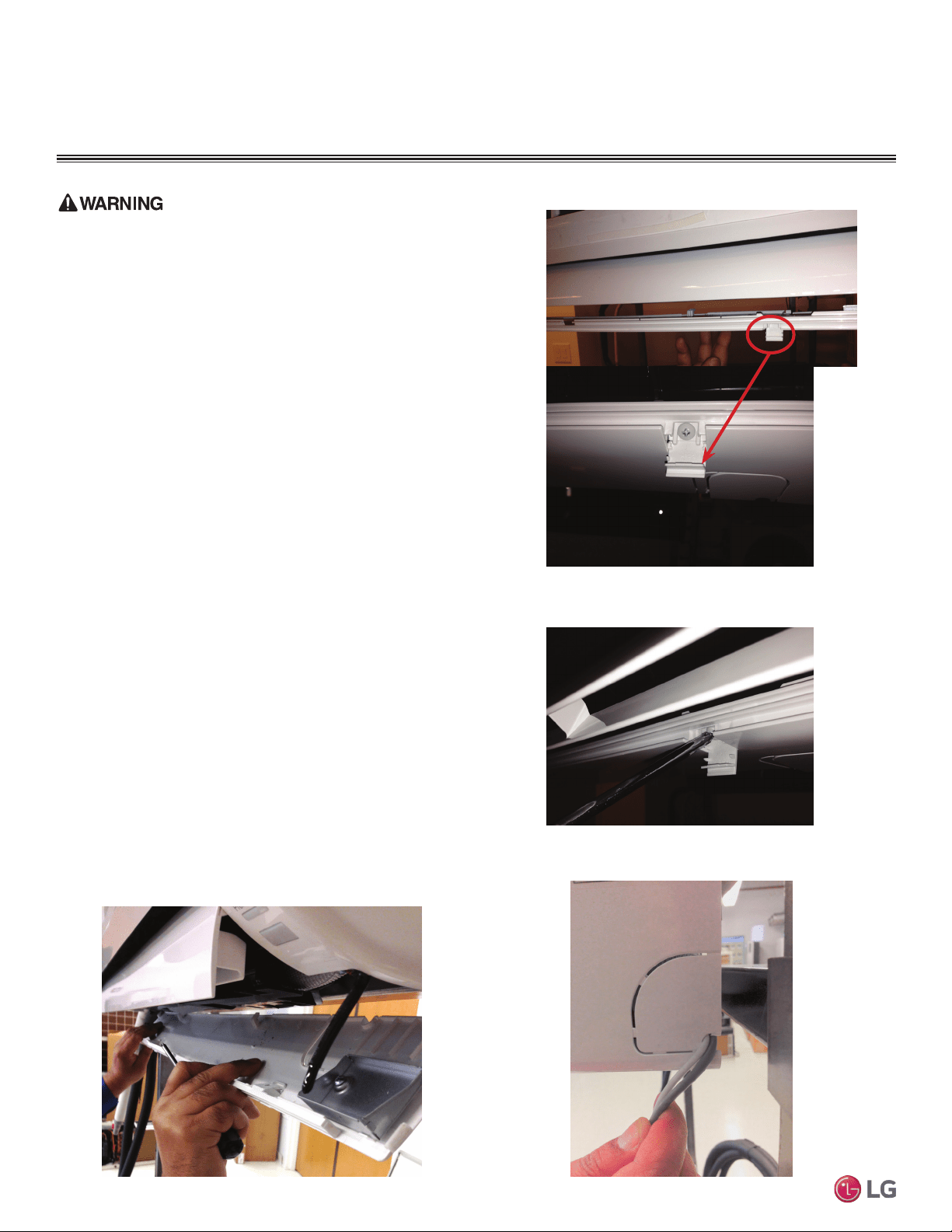
1. At the bottom panel of the indoor unit, unsnap the latches cover-
ing the phillips head screws as shown in Figure 54.
• Normally, there are three (3) screws on the panel, however, your
indoor unit model may differ.
2. Using a phillips head screwdriver, remove the screws from the
bottom panel of the indoor unit and set aside (Figure 55).
3. Remove the bottom panel (Figure 56).
• Removal is necessary to gain access to the terminal block
located at the bottom of most indoor units.
4. Route the electrical/communications wiring through the back/bot-
tom of the indoor unit (through a knockout panel, Figure 57).
5. Using a screwdriver, connect the wires as shown in Figure 58 and
Figure 59. Also refer to the appropriate wiring diagram for the IDU
(Figure 60 through Figure 63).
• Each wire should be securely attached to the terminal block.
• Ensure the green/yellow ground cable is securely connected to
the correct screw terminal.
6. When done, reattach the bottom panel to the indoor unit, being
careful to align panel using the rear tabs.
• You might need to give the panel a gentle tap with the palm of your
hand to be sure it engages at the bottom.
7. Using a phillips screwdriver, reattach the screws to the bottom
panel and secure.
8. Once screws are in place, re-snap the latches over the screws.
9. If all other piping and electrical wiring to the outdoor unit has
been completed, you can turn the system on to test.
• If you have not completed the piping connections, do not turn
power on at this time. Be sure to complete all other piping,
(along with drain hose) and wiring to the system.
Figure 54: Latch over Screws on Bottom Panel, Indoor Unit
Figure 55: Remove Screws from Bottom Panel
Figure 56: Removal (and Reattachment) of Bottom Panel
Figure 57: Indoor Unit Knockout (Communication Wires)
Loading ...
Loading ...
Loading ...