Loading ...
Loading ...
Loading ...
41
Installation Manual
Due to our policy of continuous product innovation, some specifications may change without notification.
©LG Electronics U.S.A., Inc., Englewood Cliffs, NJ. All rights reserved. “LG” is a registered trademark of LG Corp.
MA
X
MUL
TI
F
MUL
TI
F
IDU Electrical Connections Procedure
• Be sure that main power to the unit is completely off before
beginning this procedure. Electric shock can cause severe physical
injury or death.
• Follow all safety and warning information outlined at the beginning
and throughout this manual. Failure to do so may cause bodily injury
or death.
Note:
• Follow all safety and warning information outlined at the begin-
ning and throughout this manual. Failure to do so, may cause unit
failure.
• Some units might require you to remove the Control Cover from
the terminal block area. Most Control Covers are attached with a
phillips screw head.
• Connect the electrical cable to the indoor unit by connecting the
wires to the terminals on the control board individually according to
the outdoor unit connection. Be sure that the color of the wires at
the outdoor unit along with the terminal numbers are the same as
those for the indoor unit.
• Loose wiring may cause unit malfunction, or the terminal to overheat
and catch re. Terminal screws may become loose during transport.
Properly tighten the terminal connections during installation.
Power Wiring / Communications Cable Guidelines
• These instructions are for the IDU only. For ODU wiring, refer to the ODU installation manual.
• Conrm power source specications.
• Conrm that the electrical capacity is sufcient.
• Starting current must be maintained ±10 percent of the rated current marked on the outdoor unit name plate.
• Conrm cable thickness specications.
• It is recommended that a circuit breaker is installed, especially if conditions could become wet or moist.
• Include a disconnect in the power wiring system. Add an air gap contact separation of at least 1/8 inch in each active (phase) conductor.
• A voltage drop may cause the following problems:
1. Magnetic switch vibration, fuse breaks, or disturbance to the
normal function of an overload protection device.
2. Compressor will not receive the proper starting current.
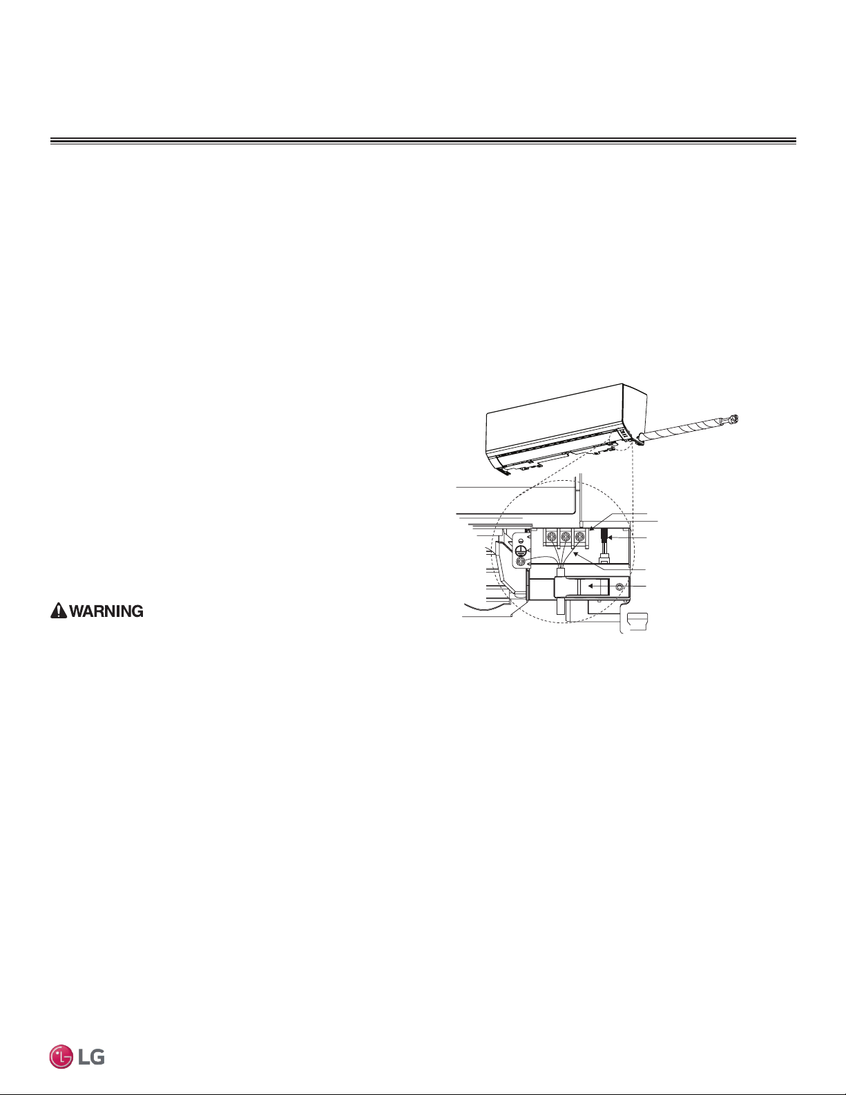
Terminal block
Power wiring /
communications cable
Wired Remote Controlle
r
Terminal (Optional)
Cable restraint
Figure 53: Typical IDU Power and Communications
Cable Connections
ELECTRICAL WIRING
Indoor Unit Electrical Connections Guidelines
The general guidelines for connecting electrical and communication
cables are similar for all standard wall-mounted indoor units; how-
ever, the connections on the terminal block may differ. Depending
on your indoor unit, the location of the terminal block on the indoor
unit might vary from these typical images. Figure 53 shows typical
connections.
The electrical connections procedure includes wiring diagrams for
each type of standard wall-mounted indoor unit.
Loading ...
Loading ...
Loading ...