
INSTRUCTION MANUAL
Cordless Trimmer
DRT50
ENGLISH: Original instructions
Read before use.
2 ENGLISH
SPECIFICATIONS
Model: DRT50
Collet chuck capacity 6 mm, 8 mm, or 1/4″
No load speed 10,000 - 30,000 min
-1
Overall length 226 mm
Rated voltage D.C. 18 V
Net weight 1.8 - 2.1 kg
• Due to our continuing program of research and development, the specications herein are subject to change
without notice.
• Specications and battery cartridge may dier from country to country.
• The weight may dier depending on the attachment(s), including the battery cartridge. The lightest and heavi-
est combinations, according to EPTA-Procedure 01/2014, are shown in the table.
Applicable battery cartridge and charger
Battery cartridge BL1815N / BL1820B / BL1830B / BL1840B / BL1850B / BL1860B
Charger DC18RC / DC18RD / DC18RE / DC18SD / DC18SE / DC18SF /
DC18SH
• Some of the battery cartridges and chargers listed above may not be available depending on your region of
residence.
WARNING: Only use the battery cartridges and chargers listed above. Use of any other battery cartridges
and chargers may cause injury and/or re.
Symbols
The followings show the symbols which may be used
for the equipment. Be sure that you understand their
meaning before use.
Read instruction manual.
Wear safety glasses.
Ni-MH
Li-ion
Only for EU countries
Due to the presence of hazardous com-
ponents in the equipment, waste electrical
and electronic equipment, accumulators
and batteries may have a negative impact
on the environment and human health.
Do not dispose of electrical and electronic
appliances or batteries with household waste!
In accordance with the European Directive
on waste electrical and electronic equip-
ment and on accumulators and batteries
and waste accumulators and batteries,
as well as their adaptation to national law,
waste electrical equipment, batteries and
accumulators should be stored separately
and delivered to a separate collection point
for municipal waste, operating in accor-
dance with the regulations on environmen-
tal protection.
This is indicated by the symbol of the
crossed-out wheeled bin placed on the
equipment.
Intended use
The tool is intended for ush trimming and proling of
wood, plastic and similar materials.
Noise
The typical A-weighted noise level determined accord-
ing to EN62841-2-17:
Work mode: rotation without load
Sound pressure level (L
pA
) : 78 dB(A)
Uncertainty (K) : 3 dB(A)
NOTE:
The declared noise emission value(s) has been
measured in accordance with a standard test method
and may be used for comparing one tool with another.
NOTE: The declared noise emission value(s)
may also be used in a preliminary assessment of
exposure.
WARNING: Wear ear protection.
WARNING: The noise emission during actual
use of the power tool can dier from the declared
value(s) depending on the ways in which the
tool is used especially what kind of workpiece is
processed.
WARNING: Be sure to identify safety mea-
sures to protect the operator that are based on an
estimation of exposure in the actual conditions of
use (taking account of all parts of the operating
cycle such as the times when the tool is switched
o and when it is running idle in addition to the
trigger time).
Vibration
The vibration total value (tri-axial vector sum) deter-
mined according to EN62841-2-17:
Work mode: rotation without load
Vibration emission (a
h
) : 2.5 m/s
2
or less
Uncertainty (K) : 1.5 m/s
2

3 ENGLISH
NOTE: The declared vibration total value(s) has been
measured in accordance with a standard test method
and may be used for comparing one tool with another.
NOTE: The declared vibration total value(s) may also
be used in a preliminary assessment of exposure.
WARNING:
The vibration emission during actual
use of the power tool can dier from the declared val-
ue(s) depending on the ways in which the tool is used
especially what kind of workpiece is processed.
WARNING: Be sure to identify safety mea-
sures to protect the operator that are based on an
estimation of exposure in the actual conditions of
use (taking account of all parts of the operating
cycle such as the times when the tool is switched
o and when it is running idle in addition to the
trigger time).
EC Declaration of Conformity
For European countries only
The EC declaration of conformity is included as Annex A
to this instruction manual.
SAFETY WARNINGS
General power tool safety warnings
WARNING: Read all safety warnings, instruc-
tions, illustrations and specications provided
with this power tool. Failure to follow all instructions
listed below may result in electric shock, re and/or
serious injury.
Save all warnings and instruc-
tions for future reference.
The term "power tool" in the warnings refers to your
mains-operated (corded) power tool or battery-operated
(cordless) power tool.
Work area safety
1. Keep work area clean and well lit. Cluttered or
dark areas invite accidents.
2. Do not operate power tools in explosive atmo-
spheres, such as in the presence of ammable
liquids, gases or dust. Power tools create sparks
which may ignite the dust or fumes.
3. Keep children and bystanders away while
operating a power tool. Distractions can cause
you to lose control.
Electrical safety
1. Power tool plugs must match the outlet. Never
modify the plug in any way. Do not use any
adapter plugs with earthed (grounded) power
tools. Unmodied plugs and matching outlets will
reduce risk of electric shock.
2. Avoid body contact with earthed or grounded
surfaces, such as pipes, radiators, ranges and
refrigerators. There is an increased risk of elec-
tric shock if your body is earthed or grounded.
3. Do not expose power tools to rain or wet con-
ditions. Water entering a power tool will increase
the risk of electric shock.
4. Do not abuse the cord. Never use the cord for
carrying, pulling or unplugging the power tool.
Keep cord away from heat, oil, sharp edges
or moving parts. Damaged or entangled cords
increase the risk of electric shock.
5.
When operating a power tool outdoors, use an
extension cord suitable for outdoor use. Use of a cord
suitable for outdoor use reduces the risk of electric shock.
6. If operating a power tool in a damp location
is unavoidable, use a residual current device
(RCD) protected supply. Use of an RCD reduces
the risk of electric shock.
7. Power tools can produce electromagnetic
elds (EMF) that are not harmful to the user.
However, users of pacemakers and other similar
medical devices should contact the maker of their
device and/or doctor for advice before operating
this power tool.
Personal safety
1. Stay alert, watch what you are doing and use
common sense when operating a power tool.
Do not use a power tool while you are tired or
under the inuence of drugs, alcohol or med-
ication. A moment of inattention while operating
power tools may result in serious personal injury.
2. Use personal protective equipment. Always
wear eye protection. Protective equipment such
as a dust mask, non-skid safety shoes, hard hat or
hearing protection used for appropriate conditions
will reduce personal injuries.
3. Prevent unintentional starting. Ensure the
switch is in the o-position before connecting
to power source and/or battery pack, picking
up or carrying the tool. Carrying power tools with
your nger on the switch or energising power tools
that have the switch on invites accidents.
4. Remove any adjusting key or wrench before
turning the power tool on. A wrench or a key left
attached to a rotating part of the power tool may
result in personal injury.
5. Do not overreach. Keep proper footing and
balance at all times. This enables better control
of the power tool in unexpected situations.
6. Dress properly. Do not wear loose clothing or
jewellery. Keep your hair and clothing away
from moving parts. Loose clothes, jewellery or
long hair can be caught in moving parts.
7. If devices are provided for the connection of
dust extraction and collection facilities, ensure
these are connected and properly used. Use of
dust collection can reduce dust-related hazards.
8.
Do not let familiarity gained from frequent use
of tools allow you to become complacent and
ignore tool safety principles. A careless action can
cause severe injury within a fraction of a second.
9. Always wear protective goggles to protect
your eyes from injury when using power tools.
The goggles must comply with ANSI Z87.1 in
the USA, EN 166 in Europe, or AS/NZS 1336
in Australia/New Zealand. In Australia/New
Zealand, it is legally required to wear a face
shield to protect your face, too.

4 ENGLISH
It is an employer's responsibility to enforce
the use of appropriate safety protective equip-
ments by the tool operators and by other per-
sons in the immediate working area.
Power tool use and care
1. Do not force the power tool. Use the correct
power tool for your application. The correct
power tool will do the job better and safer at the
rate for which it was designed.
2. Do not use the power tool if the switch does
not turn it on and o. Any power tool that cannot
be controlled with the switch is dangerous and
must be repaired.
3. Disconnect the plug from the power source
and/or remove the battery pack, if detachable,
from the power tool before making any adjust-
ments, changing accessories, or storing power
tools. Such preventive safety measures reduce
the risk of starting the power tool accidentally.
4. Store idle power tools out of the reach of chil-
dren and do not allow persons unfamiliar with
the power tool or these instructions to operate
the power tool. Power tools are dangerous in the
hands of untrained users.
5. Maintain power tools and accessories. Check
for misalignment or binding of moving parts,
breakage of parts and any other condition that
may aect the power tool’s operation. If dam-
aged, have the power tool repaired before use.
Many accidents are caused by poorly maintained
power tools.
6. Keep cutting tools sharp and clean. Properly
maintained cutting tools with sharp cutting edges
are less likely to bind and are easier to control.
7. Use the power tool, accessories and tool bits
etc. in accordance with these instructions, tak-
ing into account the working conditions and
the work to be performed. Use of the power tool
for operations dierent from those intended could
result in a hazardous situation.
8. Keep handles and grasping surfaces dry,
clean and free from oil and grease. Slippery
handles and grasping surfaces do not allow for
safe handling and control of the tool in unexpected
situations.
9. When using the tool, do not wear cloth work
gloves which may be entangled. The entangle-
ment of cloth work gloves in the moving parts may
result in personal injury.
Battery tool use and care
1. Recharge only with the charger specied by
the manufacturer. A charger that is suitable for
one type of battery pack may create a risk of re
when used with another battery pack.
2. Use power tools only with specically desig-
nated battery packs. Use of any other battery
packs may create a risk of injury and re.
3. When battery pack is not in use, keep it away
from other metal objects, like paper clips,
coins, keys, nails, screws or other small metal
objects, that can make a connection from one
terminal to another. Shorting the battery termi-
nals together may cause burns or a re.
4.
Under abusive conditions, liquid may be ejected
from the battery; avoid contact. If contact acci-
dentally occurs, ush with water. If liquid con-
tacts eyes, additionally seek medical help. Liquid
ejected from the battery may cause irritation or burns.
5. Do not use a battery pack or tool that is dam-
aged or modied. Damaged or modied batteries
may exhibit unpredictable behaviour resulting in
re, explosion or risk of injury.
6. Do not expose a battery pack or tool to re or
excessive temperature. Exposure to re or tem-
perature above 130 °C may cause explosion.
7.
Follow all charging instructions and do not charge
the battery pack or tool outside the temperature
range specied in the instructions. Charging improp-
erly or at temperatures outside the specied range may
damage the battery and increase the risk of re.
Service
1. Have your power tool serviced by a qualied
repair person using only identical replacement
parts. This will ensure that the safety of the power
tool is maintained.
2. Never service damaged battery packs. Service
of battery packs should only be performed by the
manufacturer or authorized service providers.
3. Follow instruction for lubricating and chang-
ing accessories.
Cordless trimmer safety warnings
1.
Use clamps or another practical way to secure
and support the workpiece to a stable platform.
Holding the work by your hand or against the body
leaves it unstable and may lead to loss of control.
2. Wear hearing protection during extended
period of operation.
3. Handle the trimmer bits very carefully.
4. Check the trimmer bit carefully for cracks or
damage before operation. Replace cracked or
damaged bit immediately.
5. Avoid cutting nails. Inspect for and remove all
nails from the workpiece before operation.
6. Hold the tool rmly.
7. Keep hands away from rotating parts.
8. Make sure the trimmer bit is not contacting the
workpiece before the switch is turned on.
9. Before using the tool on an actual workpiece,
let it run for a while. Watch for vibration or
wobbling that could indicate improperly
installed bit.

5 ENGLISH
10. Be careful of the trimmer bit rotating direction
and the feed direction.
11. Do not leave the tool running. Operate the tool
only when hand-held.
12. Always switch o and wait for the trimmer bit
to come to a complete stop before removing
the tool from workpiece.
13. Do not touch the trimmer bit immediately after
operation; it may be extremely hot and could
burn your skin.
14. Do not smear the base carelessly with thin-
ner, gasoline, oil or the like. They may cause
cracks in the base.
15. Use trimmer bits of the correct shank diameter
suitable for the speed of the tool.
16. Some material contains chemicals which may
be toxic. Take caution to prevent dust inhala-
tion and skin contact. Follow material supplier
safety data.
17.
Always use the correct dust mask/respirator for
the material and application you are working with.
SAVE THESE INSTRUCTIONS.
WARNING: DO NOT let comfort or familiarity
with product (gained from repeated use) replace
strict adherence to safety rules for the subject
product. MISUSE or failure to follow the safety
rules stated in this instruction manual may cause
serious personal injury.
Important safety instructions for
battery cartridge
1.
Before using battery cartridge, read all instruc-
tions and cautionary markings on (1) battery
charger, (2) battery, and (3) product using battery.
2. Do not disassemble or tamper with the battery
cartridge. It may result in a re, excessive heat,
or explosion.
3. If operating time has become excessively
shorter, stop operating immediately. It may
result in a risk of overheating, possible burns
and even an explosion.
4.
If electrolyte gets into your eyes, rinse them out
with clear water and seek medical attention right
away. It may result in loss of your eyesight.
5. Do not short the battery cartridge:
(1) Do not touch the terminals with any con-
ductive material.
(2) Avoid storing battery cartridge in a con-
tainer with other metal objects such as
nails, coins, etc.
(3) Do not expose battery cartridge to water
or rain.
A battery short can cause a large current
ow, overheating, possible burns and even a
breakdown.
6. Do not store and use the tool and battery car-
tridge in locations where the temperature may
reach or exceed 50 °C (122 °F).
7. Do not incinerate the battery cartridge even if
it is severely damaged or is completely worn
out. The battery cartridge can explode in a re.
8. Do not nail, cut, crush, throw, drop the battery
cartridge, or hit against a hard object to the
battery cartridge. Such conduct may result in a
re, excessive heat, or explosion.
9. Do not use a damaged battery.
10.
The contained lithium-ion batteries are subject to
the Dangerous Goods Legislation requirements.
For commercial transports e.g. by third parties,
forwarding agents, special requirement on pack-
aging and labeling must be observed.
For preparation of the item being shipped, consulting an
expert for hazardous material is required. Please also
observe possibly more detailed national regulations.
Tape or mask o open contacts and pack up the
battery in such a manner that it cannot move
around in the packaging.
11.
When disposing the battery cartridge, remove it from
the tool and dispose of it in a safe place. Follow your
local regulations relating to disposal of battery.
12. Use the batteries only with the products
specied by Makita. Installing the batteries to
non-compliant products may result in a re, exces-
sive heat, explosion, or leak of electrolyte.
13. If the tool is not used for a long period of time,
the battery must be removed from the tool.
14. During and after use, the battery cartridge may
take on heat which can cause burns or low
temperature burns. Pay attention to the han-
dling of hot battery cartridges.
15.
Do not touch the terminal of the tool immediately
after use as it may get hot enough to cause burns.
16. Do not allow chips, dust, or soil stuck into the
terminals, holes, and grooves of the battery
cartridge. It may result in poor performance or
breakdown of the tool or battery cartridge.
17. Unless the tool supports the use near
high-voltage electrical power lines, do not use
the battery cartridge near high-voltage electri-
cal power lines. It may result in a malfunction or
breakdown of the tool or battery cartridge.
18. Keep the battery away from children.
SAVE THESE INSTRUCTIONS.
CAUTION:
Only use genuine Makita batteries.
Use of non-genuine Makita batteries, or batteries that
have been altered, may result in the battery bursting
causing res, personal injury and damage. It will also
void the Makita warranty for the Makita tool and charger.
Tips for maintaining maximum
battery life
1.
Charge the battery cartridge before completely dis-
charged. Always stop tool operation and charge the
battery cartridge when you notice less tool power.
2.
Never recharge a fully charged battery cartridge.
Overcharging shortens the battery service life.
3.
Charge the battery cartridge with room tempera-
ture at 10 °C - 40 °C (50 °F - 104 °F). Let a hot
battery cartridge cool down before charging it.
4. When not using the battery cartridge, remove
it from the tool or the charger.
5. Charge the battery cartridge if you do not use
it for a long period (more than six months).

6 ENGLISH
FUNCTIONAL
DESCRIPTION
CAUTION: Always be sure that the tool is
switched o and the battery cartridge is removed
before adjusting or checking function on the tool.
Installing or removing battery
cartridge
CAUTION: Always switch o the tool before
installing or removing of the battery cartridge.
CAUTION: Hold the tool and the battery car-
tridge rmly when installing or removing battery
cartridge. Failure to hold the tool and the battery
cartridge rmly may cause them to slip o your hands
and result in damage to the tool and battery cartridge
and a personal injury.
1
2
3
► 1. Red indicator 2. Button 3. Battery cartridge
To remove the battery cartridge, slide it from the tool
while sliding the button on the front of the cartridge.
To install the battery cartridge, align the tongue on the
battery cartridge with the groove in the housing and slip
it into place. Insert it all the way until it locks in place
with a little click. If you can see the red indicator on the
upper side of the button, it is not locked completely.
CAUTION: Always install the battery cartridge
fully until the red indicator cannot be seen. If not,
it may accidentally fall out of the tool, causing injury to
you or someone around you.
CAUTION: Do not install the battery cartridge
forcibly. If the cartridge does not slide in easily, it is
not being inserted correctly.
Indicating the remaining battery capacity
Only for battery cartridges with the indicator
1
2
► 1. Indicator lamps 2. Check button
Press the check button on the battery cartridge to indi-
cate the remaining battery capacity. The indicator lamps
light up for a few seconds.
Indicator lamps Remaining
capacity
Lighted O Blinking
75% to 100%
50% to 75%
25% to 50%
0% to 25%
Charge the
battery.
The battery
may have
malfunctioned.
NOTE: Depending on the conditions of use and the
ambient temperature, the indication may dier slightly
from the actual capacity.
NOTE: The rst (far left) indicator lamp will blink when
the battery protection system works.
Tool / battery protection system
The tool is equipped with a tool/battery protection sys-
tem. This system automatically cuts o power to the
motor to extend tool and battery life. The tool will auto-
matically stop during operation if the tool or battery is
placed under one of the following conditions:
Overload protection
When the battery is operated in a manner that causes
it to draw an abnormally high current, the tool automat-
ically stops without any indication. In this situation, turn
the tool o and stop the application that caused the tool
to become overloaded. Then turn the tool on to restart.
7 ENGLISH
Overheat protection
When the tool or battery is overheated, the tool stops
automatically and the lamp blinks. In this case, let the
tool and battery cool before turning the tool on again.
Overdischarge protection
When the battery capacity is not enough, the tool stops
automatically. In this case, remove the battery from the
tool and charge the battery.
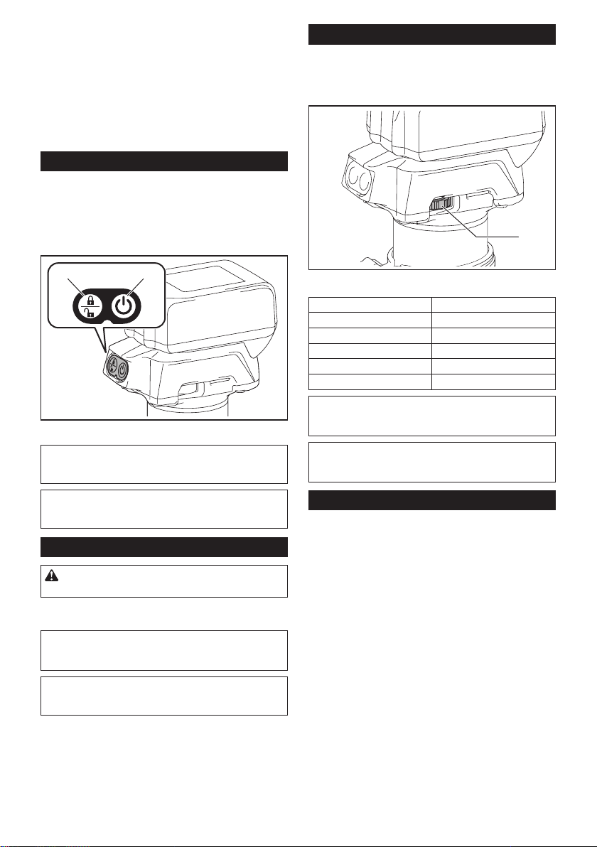
Switch action
To turn on the tool, press the lock/unlock button. The
tool turns into the standby mode. To start the tool, press
the start/stop button in the standby mode. To stop the
tool, press the start/stop button again. The tool turns
into the standby mode. To turn o the tool, press the
lock/unlock button in the standby mode.
21
► 1. Lock/unlock button 2. Start/stop button
NOTE: If the tool is left for 10 seconds without any
operation in the standby mode, the tool automatically
turns o and the lamp goes o.
NOTE: You can also stop and turn o the tool by
pressing the lock/unlock button while the tool is
operating.
Lighting up the front lamp
CAUTION: Do not look in the light or see the
source of light directly.
To turn on the lamp, press the lock/unlock button. To
turn o the lamp, press the lock/unlock button again.
NOTICE: When the tool is overheated, the lamp
ickers. Cool down the tool fully before operating
the tool again.
NOTE: Use a dry cloth to wipe the dirt o the lens of
the lamp. Be careful not to scratch the lens of lamp, or
it may lower the illumination.
Speed adjusting dial
The rotation speed of the tool can be changed by turn-
ing the speed adjusting dial. The table below shows
the number on the dial and the corresponding rotation
speed.
1
► 1. Speed adjusting dial
Number Speed
1 10,000 min
-1
2 15,000 min
-1
3 20,000 min
-1
4 25,000 min
-1
5 30,000 min
-1
NOTICE: If the tool is operated continuously at
low speed for a long time, the motor will get over-
loaded, resulting in tool malfunction.
NOTICE: When changing the speed dial from "5"
to "1", turn the dial counterclockwise. Do not turn
the dial clockwise forcibly.
Electronic function
The tool is equipped with the electronic functions for
easy operation.
• Constant speed control
The speed control function provides the constant
rotation speed regardless of load conditions.
• Soft start
The soft-start function minimizes start-up shock,
and makes the tool start smoothly.
8 ENGLISH
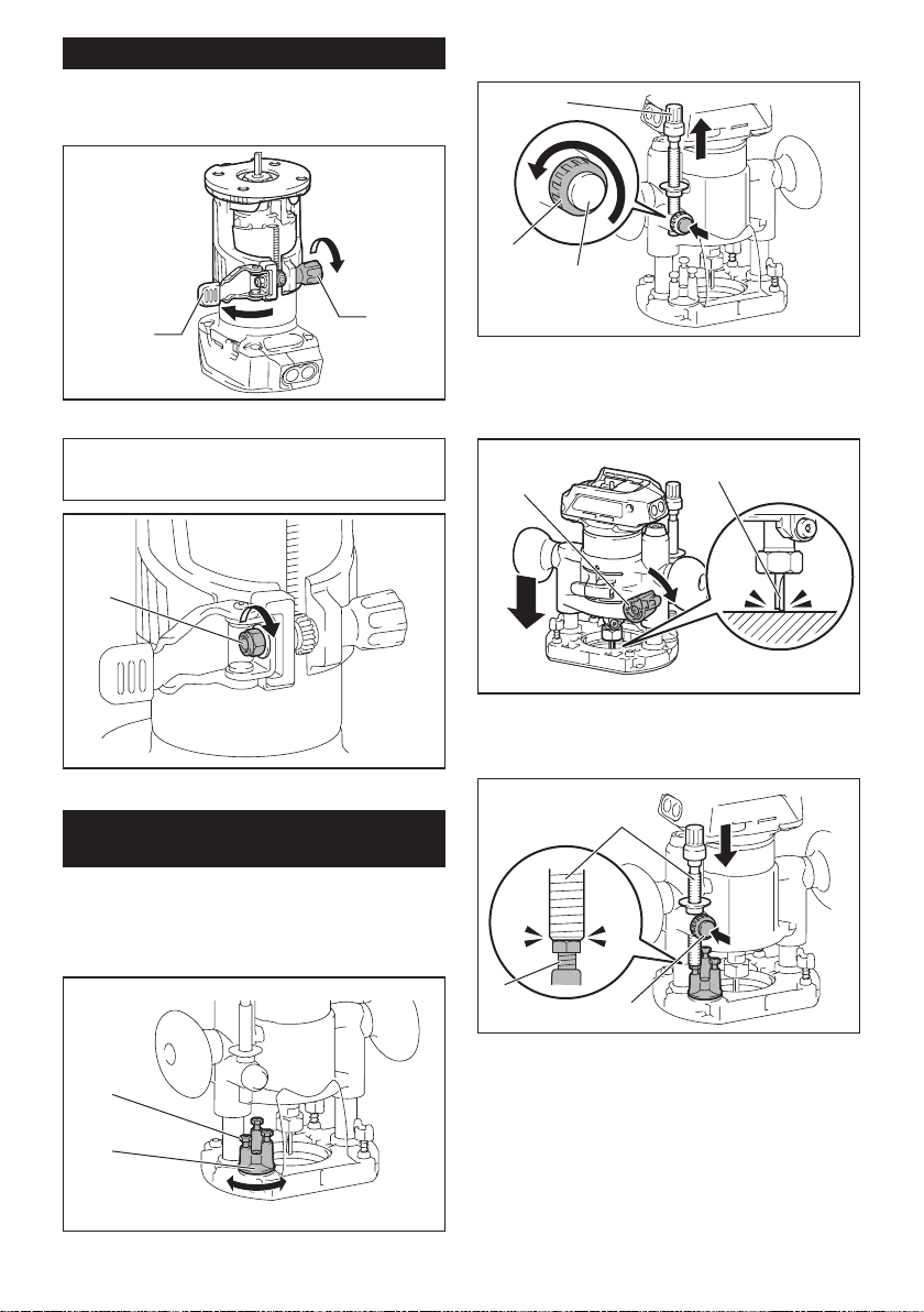
Adjusting cutting depth
To adjust the cutting depth, open the lock lever, then
move the tool base up or down by turning the adjusting
screw. After the adjustment, close the lock lever rmly.
2
1
► 1. Lock lever 2. Adjusting screw
NOTICE: If the tool is not secured after closing
the lock lever, tighten the hex nut, and then close
the lock lever.
1
► 1. Hex nut
Adjusting cutting depth with the
plunge base
Optional accessory
1. Place the tool on the at surface.
2. Select the stopper screw by rotating the stopper
base.
1
2
► 1. Stopper screw 2. Stopper base
3. Loosen the stopper pole xing nut, then pull up the
stopper pole while pressing the feed button.
2
3
1
► 1. Stopper pole 2. Fixing nut 3. Feed button
4. Push down the tool until the tip of the trimmer bit
touches the at surface, and then turn the xing lever to
secure the tool.
1
2
► 1. Fixing lever 2. Trimmer bit
5. Press down the stopper pole while pressing the
feed button until it contacts the stopper screw.
2
3
1
► 1. Stopper pole 2. Stopper screw 3. Feed button

9 ENGLISH
6. Slide the depth pointer so that the pointer indi-
cates "0" on the scale.
1
► 1. Depth pointer
7. Adjust the cutting depth by pulling up the stopper
pole while pressing the feed button.
1
2
► 1. Stopper pole 2. Feed button
8. To perform ne adjustment of the cutting depth,
turn the dial on the stopper pole so that it indicates "0".
1
► 1. Dial
9. Turn the head of the stopper pole to obtain the
desired depth. To increase the depth, turn the head
counterclockwise. To decrease the depth, turn the head
clockwise.
1
► 1. Head of the stopper pole
10. Tighten the stopper pole xing nut.
1
► 1. Fixing nut
11. Release the xing lever.
1
► 1. Fixing lever
10 ENGLISH
ASSEMBLY
CAUTION: Always be sure that the tool is
switched o and the battery cartridge is removed
before carrying out any work on the tool.
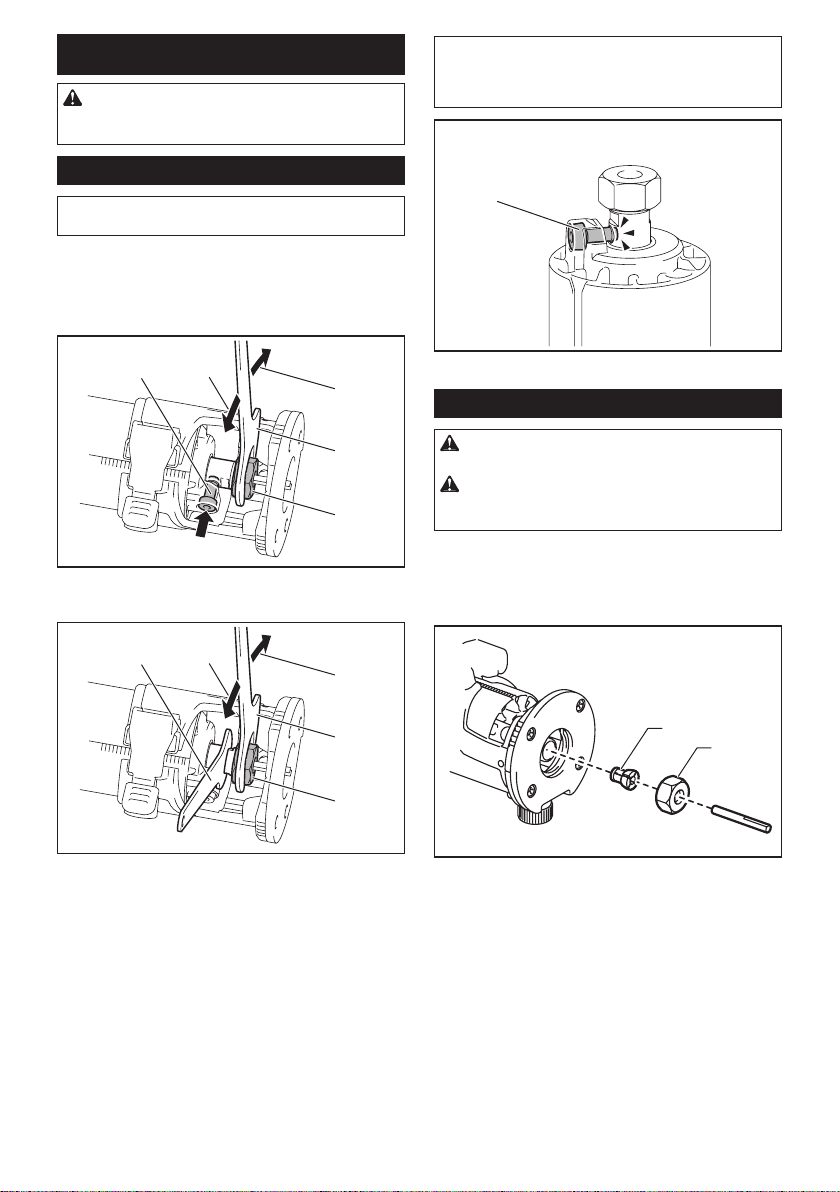
Installing or removing trimmer bit
NOTICE: Do not tighten the collet nut without
inserting the bit. The collet cone may break.
Insert the trimmer bit all the way into the collet cone.
Press the shaft lock and tighten the collet nut with the
wrench or tighten the collet nut securely with the two
wrenches. To remove the bit, follow the installation
procedure in reverse.
1
2
3
4
5
► 1. Shaft lock 2. Loosen 3. Tighten 4. Wrench
5. Collet nut
1
2
3
1
4
► 1. Wrench 2. Loosen 3. Tighten 4. Collet nut
NOTE: The shaft lock may not return to the original
position when you tighten the collet nut at the instal-
lation of the trimmer bit. The shaft lock returns to the
original position when you start the tool.
1
► 1. Shaft lock
Changing the collet cone
CAUTION: Use the correct size collet cone for
the trimmer bit which you intended to use.
CAUTION: Do not tighten the collet nut with-
out installing a trimmer bit, or the collet cone may
break.
1. Loosen the collet nut and remove.
2. Replace the installed collet cone with desired
collet cone.
3. Reinstall collet nut.
1
2
► 1. Collet cone 2. Collet nut

11 ENGLISH
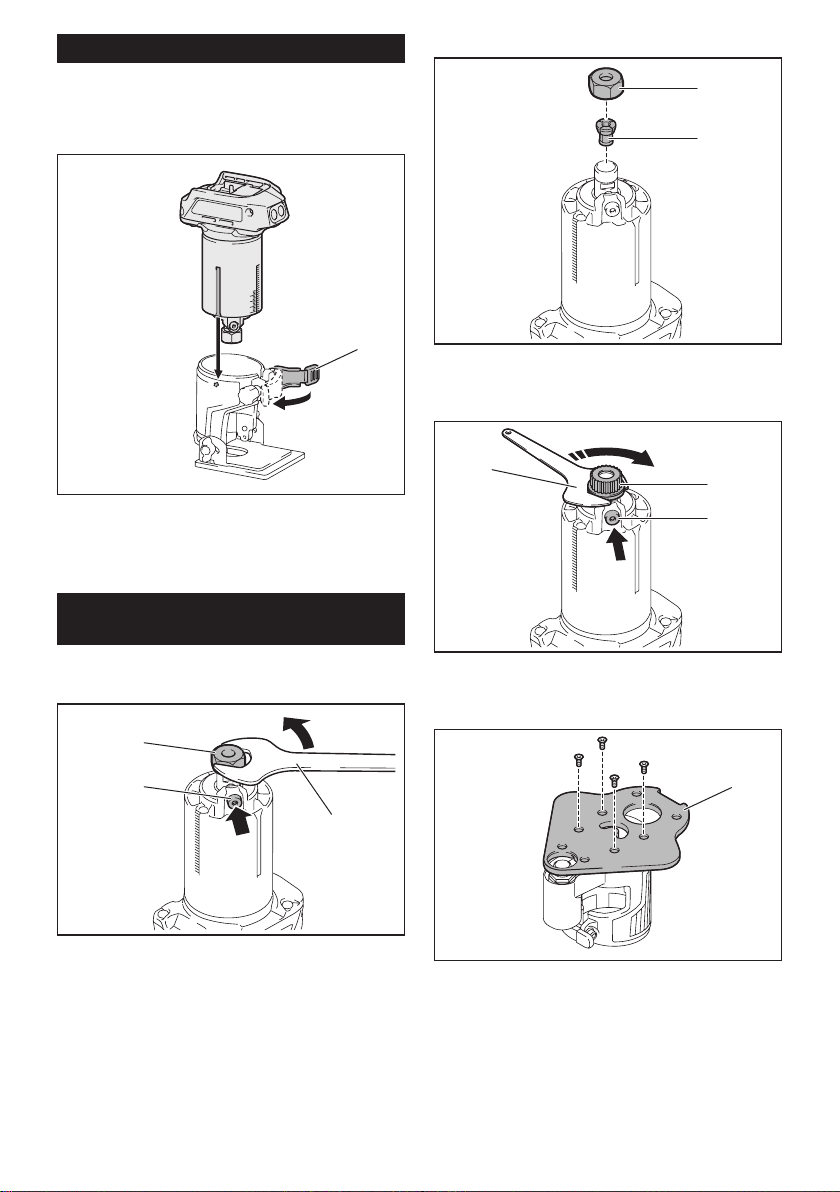
Installing or removing the trimmer
base
1. Open the lock lever of the trimmer base, then
insert the tool into the trimmer base aligning the groove
on the tool with the protrusion on the trimmer base.
1
► 1. Lock lever
NOTE: You can use the trimmer base (resin) as an
optional accessory as shown in the gure. When
using the trimmer base (resin), loosen or tighten the
thumb nut instead of opening or closing the lock lever.
1
► 1. Thumb nut
2. Close the lock lever.
3. Attach the dust nozzle to the trimmer base, and
then tighten the thumb screw.
1
2
► 1. Dust nozzle 2. Thumb screw
To remove the base, follow the installation procedure
in reverse.
CAUTION: When using the tool with the trim-
mer base, be sure to install the dust nozzle on the
trimmer base.
NOTE: In some countries, the dust nozzle may not be
included in the tool package as standard accessory.
12 ENGLISH
Installing or removing the tilt base
Optional accessory
1. Open the lock lever of the tilt base, then insert the
tool into the tilt base aligning the groove on the tool with
the protrusion on the tilt base.
1
► 1. Lock lever
2. Close the lock lever.
To remove the base, follow the installation procedure
in reverse.
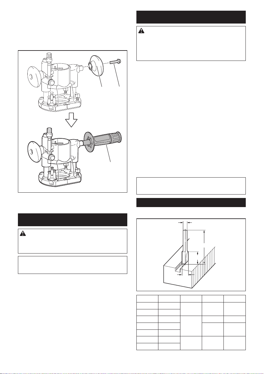
Installing or removing the oset
base
Optional accessory
1. Press the shaft lock, then loosen the collet nut.
1
2
3
► 1. Collet nut 2. Shaft lock 3. Wrench
2. Remove the collet nut and the collet cone.
1
2
► 1. Collet nut 2. Collet cone
3. Install the pulley on the tool by pressing the shaft
lock and tightening the pulley with the wrench.
1
2
3
► 1. Wrench 2. Pulley 3. Shaft lock
4. Loosen the screws on the base plate, and then
remove the base plate.
1
► 1. Base plate
13 ENGLISH
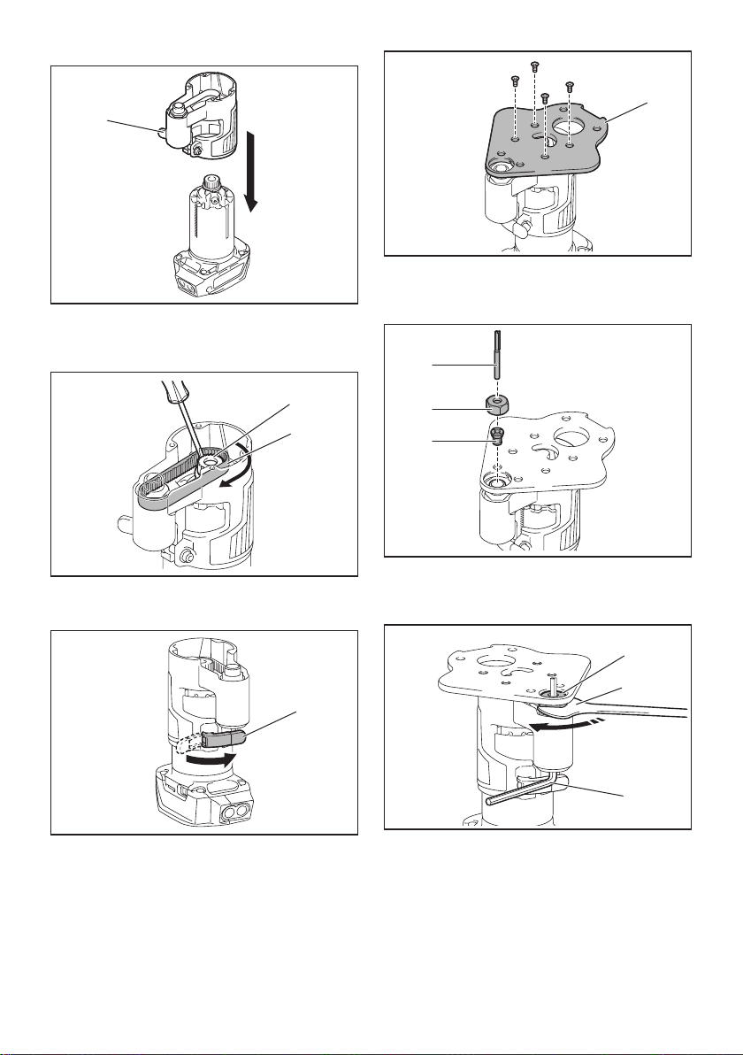
5. Open the lock lever of the oset base, then insert
the tool into the oset base.
1
► 1. Lock lever
6. Mount the belt to the pulley by rotating the belt
manually.
2
1
► 1. Pulley 2. Belt
7. Close the lock lever.
1
► 1. Lock lever
8. Attach the base plate by tightening the screws.
1
► 1. Base plate
9. Insert the collet cone and the trimmer bit into the
oset base, and then tighten the collet nut.
1
2
3
► 1. Trimmer bit 2. Collet nut 3. Collet cone
10. Insert the hex wrench into the hole of the oset
base, and then tighten the collet nut with the wrench.
1
2
3
► 1. Collet nut 2. Wrench 3. Hex wrench
To remove the base, follow the installation procedure
in reverse.
14 ENGLISH
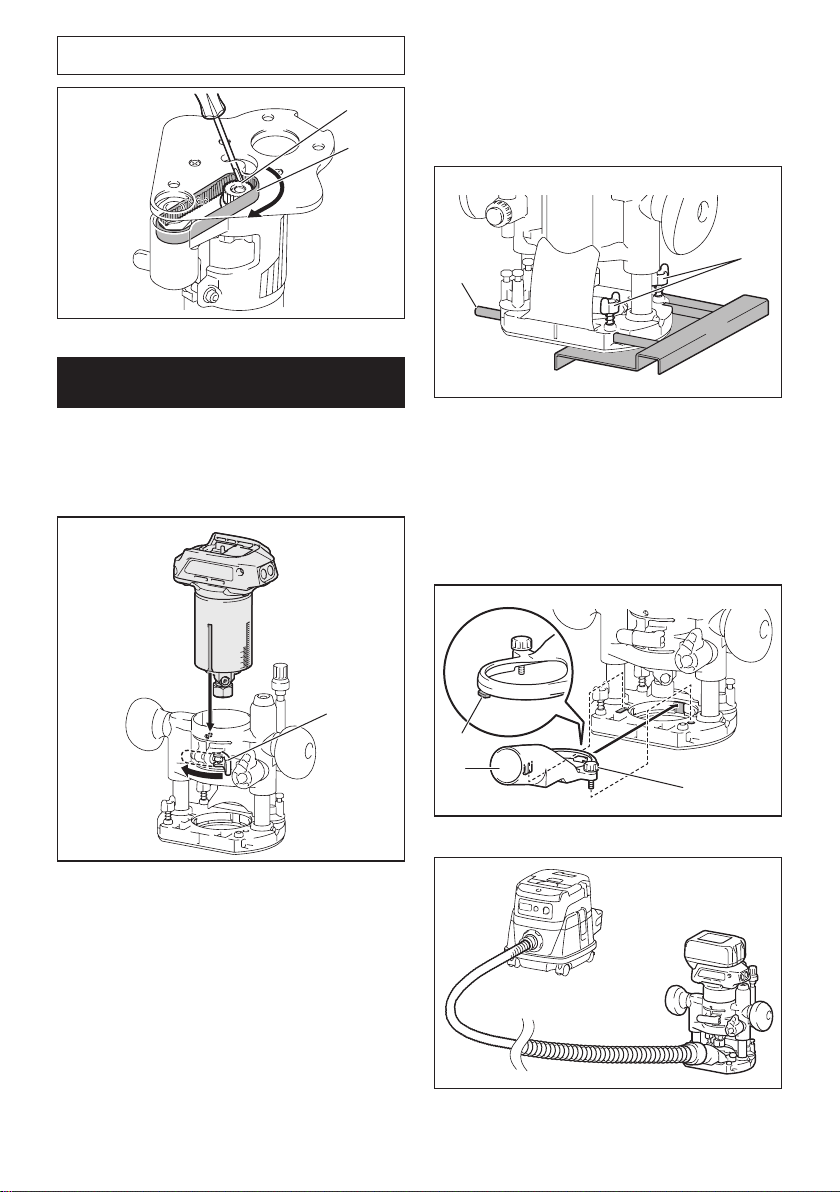
NOTE: You can also mount the belt to the pulley with-
out removing the base plate as shown in the gure.
2
1
► 1. Pulley 2. Belt
Installing or removing the plunge
base
Optional accessory
1. Open the lock lever of the plunge base, then insert
the tool into the plunge base all the way aligning the
groove on the tool with the protrusion on the plunge
base.
1
► 1. Lock lever
2. Close the lock lever.
To remove the base, follow the installation procedure
in reverse.
Installing or removing the parallel
ruler on the plunge base
Optional accessory
Insert the guide bars into the holes in the plunge base,
and then tighten the wing bolts. To remove the ruler,
follow the installation procedure in reverse.
1
2
► 1. Wing bolt 2. Guide bar
Installing or removing the dust
nozzle on the plunge base
Insert the dust nozzle into the plunge base so that the
protrusion on the dust nozzle ts in the notch in the
plunge base, and then tighten the thumb screw on the
dust nozzle. To remove the nozzle, follow the installa-
tion procedure in reverse.
1
2
3
► 1. Protrusion 2. Dust nozzle 3. Thumb screw

15 ENGLISH
OPERATION
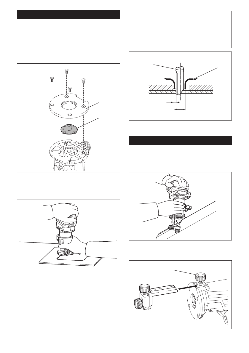
Using the tool with the trimmer base
Set the tool base on the workpiece without the trimmer
bit making any contact. Turn the tool on and wait until
the bit attains full speed. Move the tool forward over
the workpiece surface. Keep the tool base ush while
moving the tool.
When cutting the edge, be sure to keep the workpiece
surface on the left side of the trimmer bit in the feed
direction.
NOTE: Before cutting on the actual workpiece, it is
recommended to make a sample cut. The proper feed
speed depends on the trimmer bit size, the kind of
workpiece, and depth of cut. Moving the tool forward
too fast may cause a poor quality of cut, or damage
to the bit or motor. Moving the tool forward too slowly
may burn and mar the cutting surface.
When using the trimmer shoe, the straight guide, or the
trimmer guide, be sure to keep it on the right side in the
feed direction. This will help to keep it ush with the side
of the workpiece.
1
3
2
► 1. Trimmer bit 2. Workpiece 3. Straight guide
NOTICE: Since excessive cutting may cause
overload of the motor or diculty in controlling
the tool, the depth of cut should not be more than
3 mm at a pass when cutting grooves. When you
wish to cut grooves more than 3 mm deep, make
several passes with progressively deeper bit settings.
Using the straight guide
Optional accessory
1. Assemble the straight guide with the bolt and the
wing nut.
2
1
► 1. Bolt 2. Wing nut
2. Attach the straight guide to the trimmer base with
the clamp screw.
1
► 1. Clamp screw
3. Loosen the wing nut on the straight guide and
adjust the distance between the bit and the straight
guide. At the desired distance, tighten the wing nut.
1
► 1. Wing nut

16 ENGLISH
4. Move the tool with the straight guide ush with the
side of the workpiece.
If the distance (A) between the side of the workpiece
and the cutting position is too wide for the straight
guide, or if the side of the workpiece is not straight, the
straight guide cannot be used.
In this case, rmly clamp a straight board to the work-
piece and use it as a guide against the trimmer base.
Feed the tool in the direction of the arrow.
A
Using the straight guide for circular work
For circular work, assemble the straight guide as shown
in the gures. The minimum and maximum radius of
circles to be cut (distance between the center of circle
and the center of bit) are as follows:
• Minimum: 70 mm
• Maximum: 221 mm
For cutting circles between 70 mm and 121 mm in
radius.
1
► 1. Center hole
For cutting circles between 121 mm and 221 mm in
radius.
1
► 1. Center hole
NOTE: Circles between 172 mm and 186 mm in
radius cannot be cut using this guide.
Align the center hole in the straight guide with the cen-
ter of the circle to be cut. Drive a nail less than 6 mm
in diameter into the center hole to secure the straight
guide. Pivot the tool around the nail in the clockwise
direction.
2
1
► 1. Nail 2. Center hole
17 ENGLISH
Using the templet guide
Optional accessory
The templet guide allows for repetitive cut with templet
patterns by using a templet.
1. Loosen the screws on the base plate, and then
remove the base plate from the trimmer base.
2. Place the templet guide on the base, and then
attach the base plate by tightening the screws.
1
2
► 1. Base plate 2. Templet guide
3. Place the tool on the templet and move the tool
with the templet guide sliding along the side of the
templet.
NOTE: The actual cut size on the workpiece is slightly
dierent from the templet. The dierence is the dis-
tance (X) between the trimmer bit and the outside of
the templet guide. The distance (X) can be calculated
by using the following equation:
Distance (X) = (outside diameter of templet guide -
trimmer bit diameter) / 2
1
2
3
4
► 1. Trimmer bit 2. Templet guide 3. Distance (X)
4. Outside diameter of templet guide
Using the trimmer guide
Optional accessory
The trimmer guide allows for trimming the curved side
like veneers for furniture by moving the guide roller
along the side of the workpiece.
1. Loosen the clamp screw, then install the trimmer
guide on the trimmer base, and then tighten the clamp
screw.
1
► 1. Clamp screw
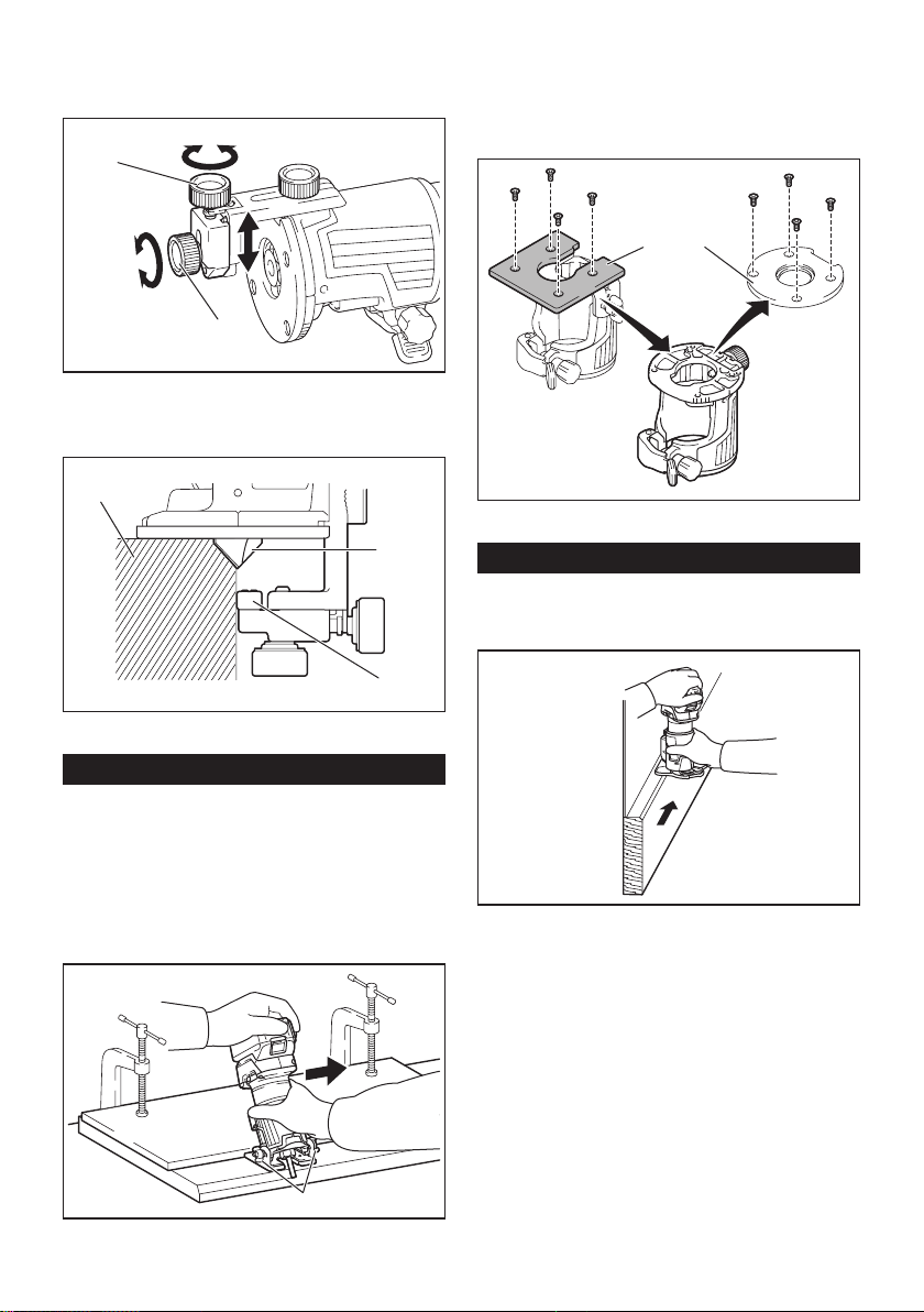
18 ENGLISH
2.
Loosen the clamp screw and adjust the distance
between the trimmer bit and the trimmer guide by turning
the adjusting screw (1 mm per turn). At the desired dis-
tance, tighten the clamp screw to secure the trimmer guide.
1
2
► 1. Adjusting screw 2. Clamp screw
3. Move the tool with the guide roller riding the side
of the workpiece.
1
2
3
► 1. Workpiece 2. Bit 3. Guide roller
Using the tool with the tilt base
The tilt base is used for trimming the edge of laminate
sheet or similar materials.
The tilt base is convenient for chamfering. Loosen the
wing screws, then tilt the tool at the desired angle, and
then tighten the wing screws.
Firmly clamp a straight board to the workpiece and use
it as a guide against the tilt base. Feed the tool in the
direction of the arrow.
1
► 1. Wing screw
Using the tilt base plate with the
trimmer base
To use the trimmer base with a square base plate,
remove the base plate from the tilt base, and then
attach it to the trimmer base.
12
► 1. Tilt base plate 2. Trimmer base plate
Using the tool with the oset base
The oset base is used for trimming the edge of lami-
nate sheet or similar materials. The oset base is con-
venient for work in a tight area.
19 ENGLISH
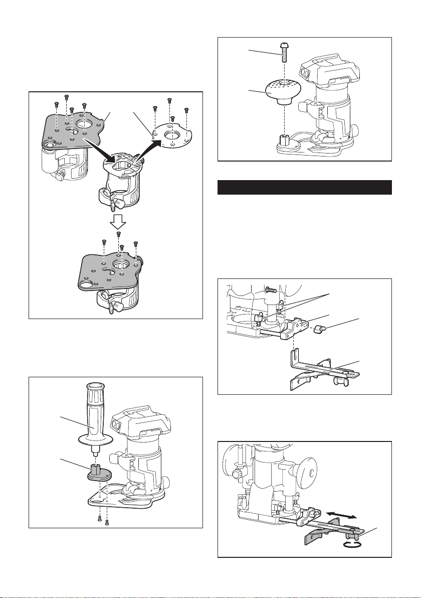
Using the trimmer base with the
oset base plate and grip
The oset base plate can also be used with a trimmer
base and a grip attachment (optional accessory) for
more stability.
1. Loosen the screws on the base plate, then remove
the base plate from the oset base.
12
► 1. Oset base plate 2. Trimmer base plate
2. Attach the oset base plate to the trimmer base by
tightening the screws.
3. Attach the grip attachment and the bar type grip to
the oset base plate by tightening the screws.
2
1
► 1. Bar type grip 2. Grip attachment
The knob type grip removed from the plunge base can
be installed on the oset base instead of the bar type grip.
1
2
► 1. Screw 2. Knob type grip
Using the tool with the plunge base
Always hold the grips rmly with both hands during opera-
tion. Operate the tool in the same way as the trimmer base.
Using the straight guide
Optional accessory
1.
Install the straight guide to the guide holder by
tightening the wing nut. Insert the guide holder into the
holes in the plunge base, and then tighten the wing bolts.
1
2
3
4
►
1. Wing bolt 2. Guide holder 3. Wing nut 4. Straight guide
2. Loosen the wing nut on the straight guide and
adjust the distance between the bit and the straight
guide. At the desired distance, tighten the wing nut.
1
► 1. Wing nut
20 ENGLISH
3. Operate the tool in the same way as the straight
guide for the trimmer base.
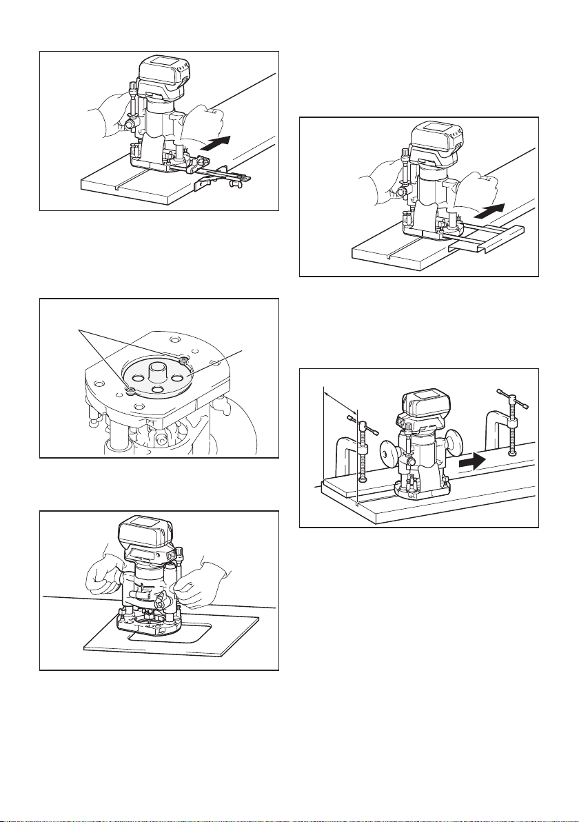
Using the templet guide
Optional accessory
1. Loosen the screws on the base and remove them.
Place the templet guide on the base, and then tighten
the screws.
1
2
► 1. Screw 2. Templet guide
2. Operate the tool in the same way as the templet
guide for the trimmer base.
Using the parallel ruler
The parallel ruler is eectively used for straight cuts
when chamfering or grooving. Adjust the distance
between the bit and the parallel ruler. At the desired
distance, tighten the wing bolts to secure the parallel
ruler. When cutting, move the tool with the parallel ruler
ush with the side of the workpiece.
If the distance (A) between the side of the workpiece
and the cutting position is too wide for the parallel ruler,
or if the side of the workpiece is not straight, the parallel
ruler cannot be used.
In this case, rmly clamp a straight board to the work-
piece and use it as a guide against the plunge base.
Feed the tool in the direction of the arrow.
A
21 ENGLISH
Changing knob type grip to bar type
grip
To install the bar type grip on the plunge base, loosen
the screw of the knob type grip, then remove the knob
type grip, and then install the bar type grip by tightening
it.
12
3
► 1. Knob type grip 2. Screw 3. Bar type grip
MAINTENANCE
CAUTION: Always be sure that the tool is
switched o and the battery cartridge is removed
before attempting to perform inspection or
maintenance.
NOTICE: Never use gasoline, benzine, thinner,
alcohol or the like. Discoloration, deformation or
cracks may result.
To maintain product SAFETY and RELIABILITY,
repairs, any other maintenance or adjustment should
be performed by Makita Authorized or Factory Service
Centers, always using Makita replacement parts.
OPTIONAL ACCESSORIES
CAUTION: These accessories or attachments
are recommended for use with your Makita tool
specied in this manual. The use of any other
accessories or attachments might present a risk of
injury to persons. Only use accessory or attachment
for its stated purpose.
If you need any assistance for more details regard-
ing these accessories, ask your local Makita Service
Center.
• Straight and groove forming bits
• Edge forming bits
• Laminate trimming bits
• Straight guide assembly
• Trimmer guide assembly
• Trimmer base assembly
• Trimmer base assembly (resin)
• Tilt base assembly
• Plunge base assembly
• Oset base assembly
• Grip attachment
• Templet guide
• Collet cone
• Wrench 13
• Wrench 22
• Makita genuine battery and charger
NOTE: Some items in the list may be included in the
tool package as standard accessories. They may
dier from country to country.
Trimmer bits
Straight bit
D
A
L1
L2
D A L1 L2
20 6 20 50 15
20E 1/4"
8 8 8 60 25
8 6 50 18
8E 1/4"
6 6 6 50 18
6E 1/4"
Unit: mm
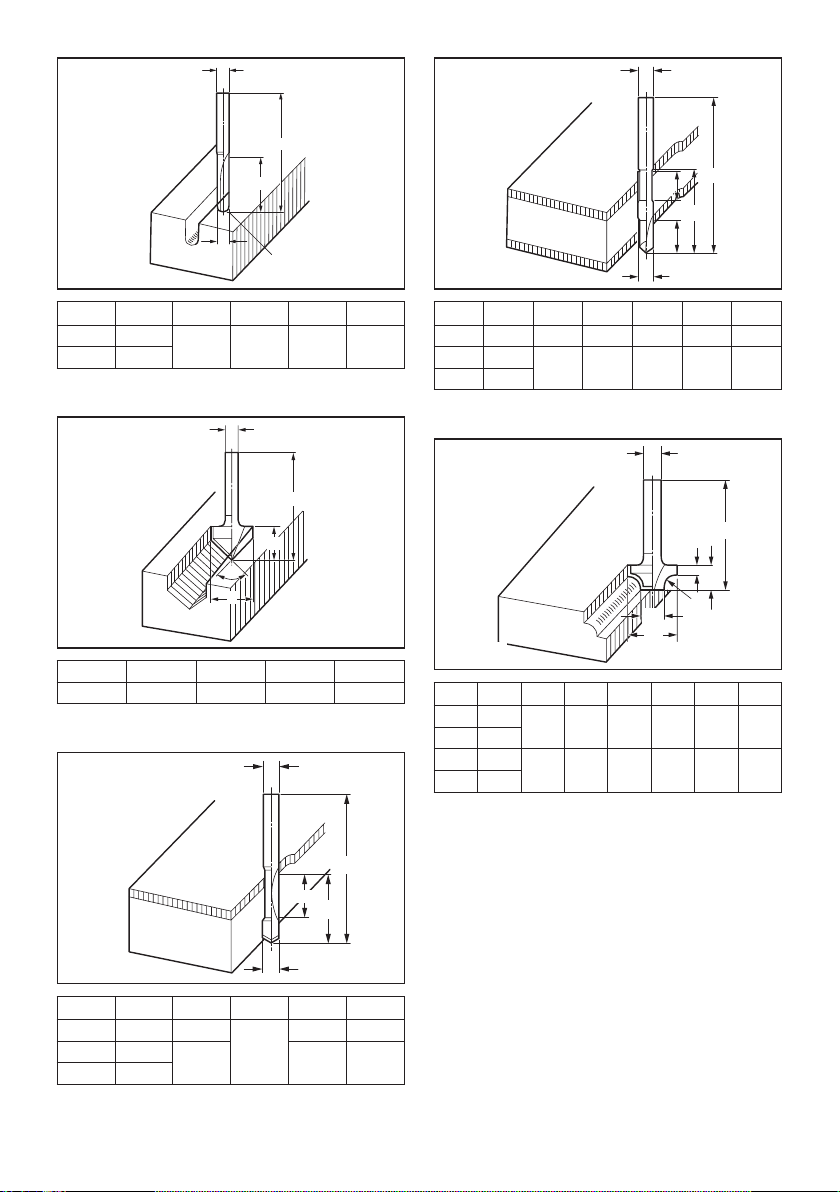
22 ENGLISH
"U" Grooving bit
D
A
L1
L2
R
D A L1 L2 R
6 6 6 50 18 3
6E 1/4"
Unit: mm
"V" Grooving bit
D
A
L1
L2
θ
D A L1 L2 θ
1/4" 20 50 15 90°
Unit: mm
Drill point ush trimming bit
D
A
L1
L2
L3
D A L1 L2 L3
8 8 8 60 20 35
6 6 6 18 28
6E 1/4"
Unit: mm
Drill point double ush trimming bit
D
A
L1
L2
L3
L4
D A L1 L2 L3 L4
8 8 8 80 95 20 25
6 6 6 70 40 12 14
6E 1/4"
Unit: mm
Corner rounding bit
D
A1
A2
L1
L2
L3
R
D A1 A2 L1 L2 L3 R
8R 6 25 9 48 13 5 8
8RE 1/4"
4R 6 20 8 45 10 4 4
4RE 1/4"
Unit: mm
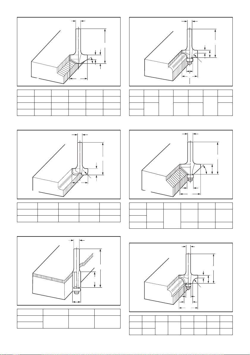
23 ENGLISH
Chamfering bit
D
A
θ
L1
L2
L3
D A L1 L2 L3 θ
6 23 46 11 6 30°
6 20 50 13 5 45°
6 20 49 14 2 60°
Unit: mm
Cove beading bit
D
A
L1
L2
R
D A L1 L2 R
6 20 43 8 4
6 25 48 13 8
Unit: mm
Ball bearing ush trimming bit
D
A
L1
L2
D A L1 L2
6 10 50 20
1/4"
Unit: mm
Ball bearing corner rounding bit
D
A1
A2
L1
L2
L3
R
D A1 A2 L1 L2 L3 R
6 15 8 37 7 3.5 3
6 21 40 10 6
1/4"
Unit: mm
Ball bearing chamfering bit
D
A1
A2
L1
L2
θ
D A1 A2 L1 L2 θ
6 26 8 42 12 45°
1/4"
6 20 41 11 60°
Unit: mm
Ball bearing beading bit
D
A1
A2
A3
L1
L2
L3
R
D A1 A2 A3 L1 L2 L3 R
6 20 12 8 40 10 5.5 4
6 26 42 12 4.5 7
Unit: mm
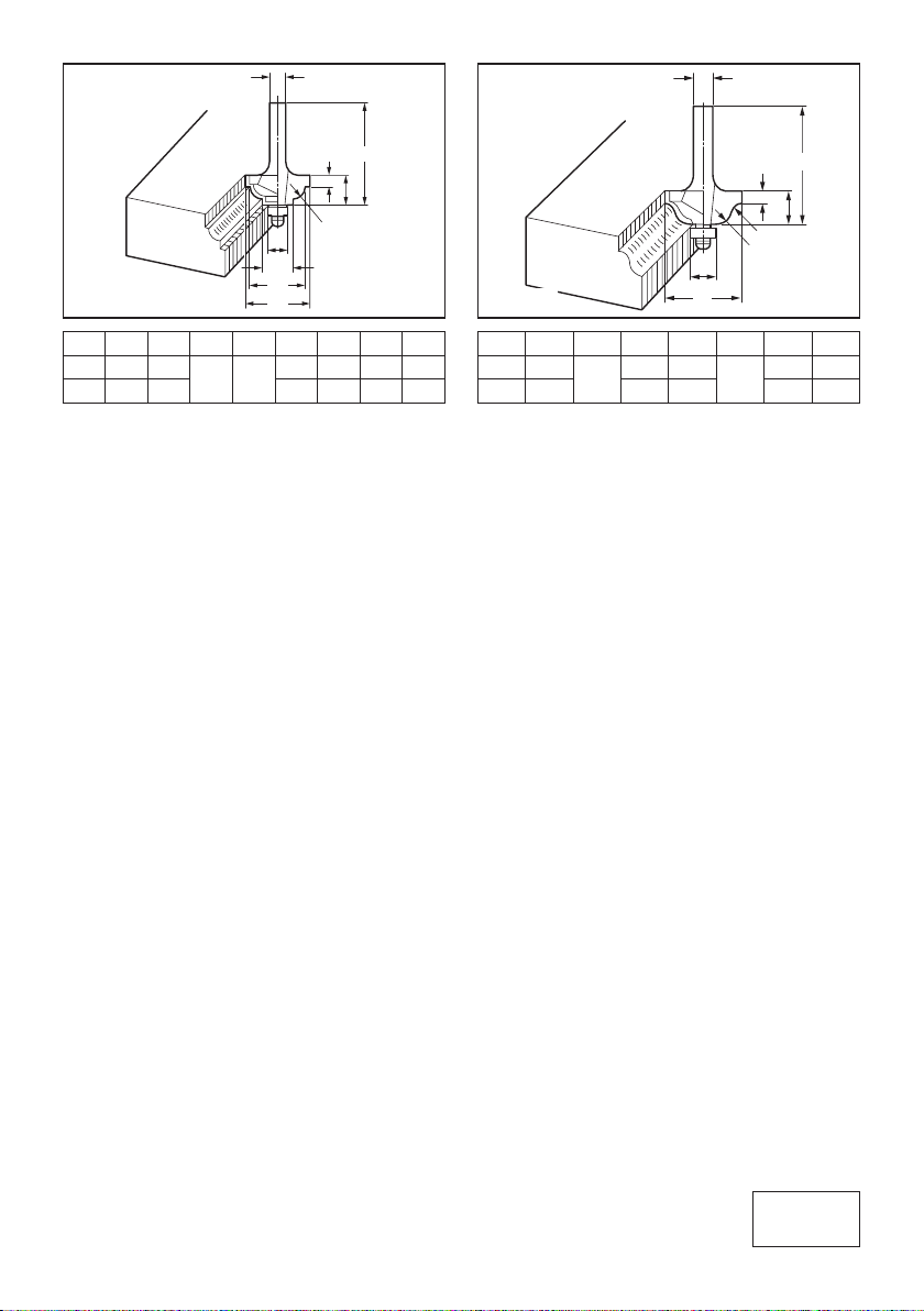
Ball bearing cove beading bit
D
A1
A2
A3
A4
L1
L2
L3
R
D A1 A2 A3 A4 L1 L2 L3 R
6 20 18 12 8 40 10 5.5 3
6 26 22 42 12 5 5
Unit: mm
Ball bearing roman ogee bit
D
A1
A2
L1
L2
L3
R1
R2
D A1 A2 L1 L2 L3 R1 R2
6 20 8 40 10 4.5 2.5 4.5
6 26 42 12 3 6
Unit: mm
www.makita.com
Makita Europe N.V.
Makita Corporation
3-11-8, Sumiyoshi-cho,
Anjo, Aichi 446-8502 Japa
n
Jan-Baptist Vinkstraat 2,
3070 Kortenberg, Belgium
885585H221
EN
20210513