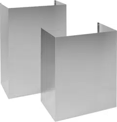
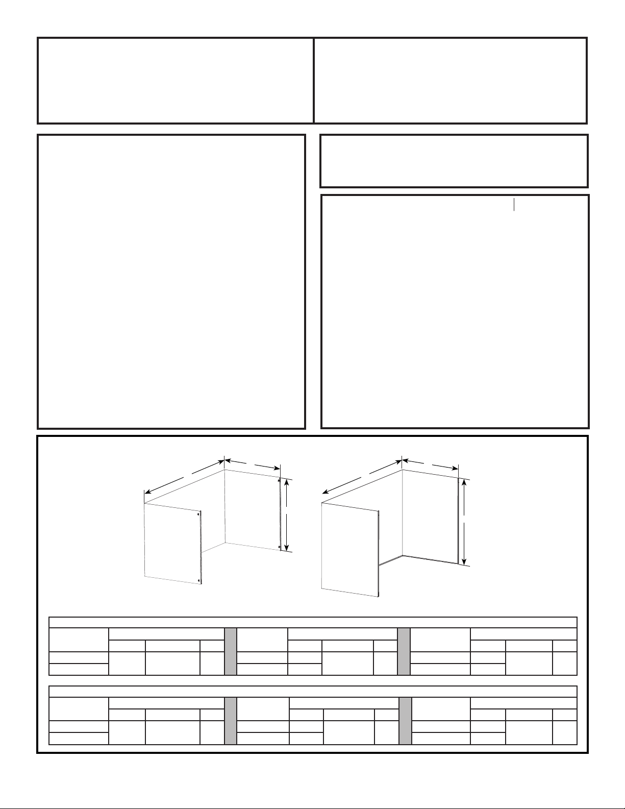
ZX8D13SPXX, ZX8D14SPXX
ZX10D13SPXX, ZX10D14SPXX
ZX12D13SPXX, ZX12D14SPXX
8’, 10’, & 12’ Duct Cover Kits
BEFORE YOU BEGIN
Read these instructions completely and carefully.
■ IMPORTANT — Save these instructions
for local inspector’s use.
■ IMPORTANT — Observe all governing
codes and ordinances.
■ Note to Installer — Be sure to leave these
instructions with the consumer.
■ Note to Consumer — Keep these instructions with
your Owner’s Manual for future reference.
■ These instructions are applicable to 8’, 10’, and 12’
duct cover kit.
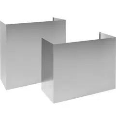
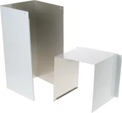
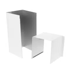
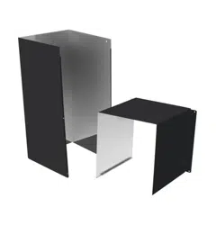
■ The duct cover kits include an upper and a lower
duct cover.
■ The upper duct cover telescopes within the lower
duct cover to reach the desired ceiling height.
■ The installation hardware includes wall brackets to
secure duct covers to the wall.
Installation
Instructions
TOOLS AND MATERIALS REQUIRED
■Glovestoprotectagainstsharpedges
■Safetyglasses
■#2Phillipsscrewdrivers
■Drillwith1/8”bits
■Level
■Pencil
This Kit Includes
■UpperDuctCover
■LowerDuctCover
■2wallBrackets
■Hardwarepackagewith
-Screws3.1x9.5P013QTY:10
-WallAnchorsQTY:4
-Screw4.2x44PZ1QTY:4
31-2000879 Rev. 0 04-21GEA
NOTE: Before making any holes for installations,
determine which venting method will be used and
calculate all measurements.
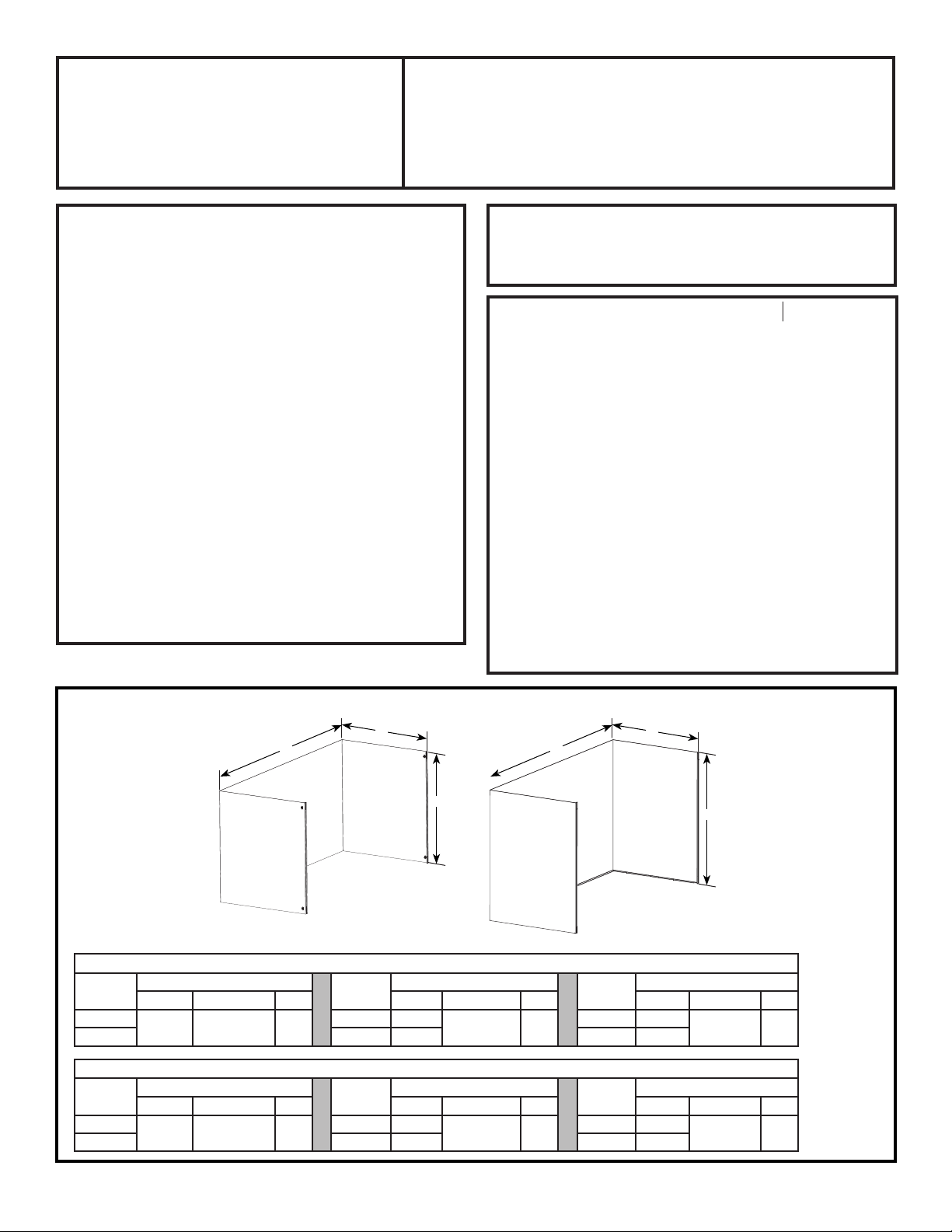
H
D
W
H
D
W
UpperDuctCover LowerDuctCover
36” Models
Duct
Cover
8’ Kit Duct
Cover
10’ Kit Duct
Cover
12’ Kit
H W D H W D H W D
Upper
4-1/2” 23-1/4” 15”
Upper 17”
23-1/4” 15”
Upper 27”
23-1/4” 15”
Lower Lower 20” Lower 34”
48” Models
Duct
Cover
8’ Kit Duct
Cover
10’ Kit Duct
Cover
12’ Kit
H W D H W D H W D
Upper
4-1/2” 35-1/4” 15”
Upper 17”
35-1/4” 15”
Upper 27”
35-1/4” 15”
Lower Lower 20” Lower 34”
■Seetablesbelowforproductdimensions.
2 31-2000879 Rev. 0
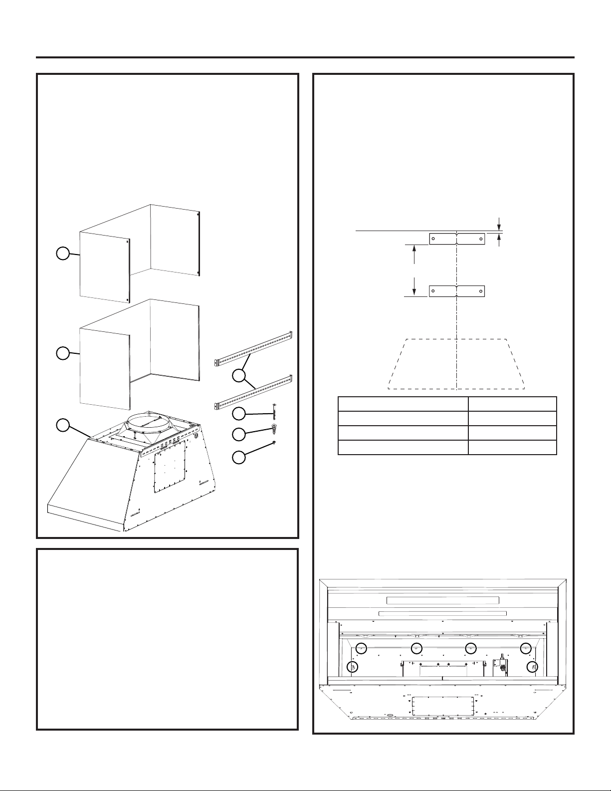
HOOD COMPONENTS
A-RangeHood
B - Screws 3.1x9.5P013 (10)
C-LowerDuctCover(1)
D-UpperDuctCover(1)
E-WallAnchors(4)
F - Wall Bracket (2)
G-Screws4.2x44PZ1(4)
INSTALLATION OF DUCT COVER KIT
(CONT.)
3. Measure straight down a distance (X) from the
bottom of the first wall bracket and make a
horizontalmark.Placethesecondwallbracket(F)
above this mark and align the center of the bracket
with the centerline of the hood. Mark bracket holes.
Remove the bracket and drill 2 clearance holes
forwallanchorswith1/16”drillbit.Installthewall
anchors(E)andsecuresecondwallbrackettothe
wallusingscrews(G).
4.Securetheupperductcovertothewallbracket
using4screws(B).Refertotheinstallationheight
tables to verify available ceiling heights.
5.Placethelowerductcoverontopofthehood.
Slightly spread the sides of the cover apart and
snap to the upper duct cover. Secure the lower
duct cover to the hood body from inside the hood
using6screws(B)atlocationsshownbelow.
Installation
C
L
1/16"
Ceiling
x
A
C
D
F
G
E
B
INSTALLATION OF DUCT COVER KIT
1. Finish hood installation as per the hood install
instructions.
2.Placewallbracket(F)againstthebackwallsothat
thetopedgeis1/16”fromtheceilingandlevel.
Align the center of the bracket with the center
line of the hood and mark bracket holes. Usethe
outermost bracket holes to secure to wall. Remove
the bracket and drill 2 clearance holes for wall
anchorswith1/16”drillbit.Installthewallanchors
(E)andsecurethebrackettothewallusingscrews
(G).
Duct Cover Kit “X”
8’ Kit 3”
10’ Kit 15-1/2”
12”Kit 25-1/2”

31-2000879 Rev. 0 3
Installation
ZX8D13SPSS
ORZX8D14SPSS
ZX10D13SPSS
ORZX10D14SPSS
ZX12D13SPSS
ORZX12D14SPSS
CeilingDuctCoverupto8ft. HighCeilingDuctCoverup
to 10 ft.
HighCeilingDuctCoverup
to 12 ft.
CeilingHeight
(ft./in.)
Installation
OverGas
Range
Installation
OverElectric
Range
CeilingHeight
(ft./in.)
Installation
OverGas
Range
Installation
OverElectric
Range
CeilingHeight
(ft./in.)
Installation
OverGas
Range
Installation
OverElectric
Range
7’0” 24 8’3” 24 9’4” 24
7’1” 24-25 8’4” 24-25 9’5” 24-25
7’2” 24-26 8’5” 24-26 9’6” 24-26
7’3” 25-27 8’6” 24-27 9’7” 24-27
7’4” 26-28 8’7” 24-28 9’8” 24-28
7’5” 27-29 8’8” 24-29 9’9” 24-29
7’6” 28-30 8’9” 24-30 9’10” 24-30
7’7” 29-31 8’10” 24-31 9’11” 24-31
7’8” 30 30-32 8’11” 30 24-32 10’0” 30 24-32
7’9” 30-31 31-33 9’0” 30-31 24-33 10’1” 30-31 24-33
7’10” 30-32 32-34 9’1” 30-32 24-34 10’2” 30-32 24-34
7’11” 31-33 33-35 9’2” 30-33 24-35 10’3” 30-33 24-35
8’0” 32-34 34-36 9’3” 30-34
24-36
10’4” 30-34
24-36
8’1” 33-35 35-36 9’4” 30-35 10’5” 30-35
8’2” 34-36 36 9’5”
30-36
10’6”
30-36
8’3” 35-36 9’6” 10’7”
8’4” 36 9’7” 25-36 10’8”
9’8” 26-36 10’9”
9’9” 27-36 10’10”
9’10” 28-36 10’11”
9’11” 29-36 11’0”
10’0” 30-36 11’1”
10’1” 31-36 11’2”
10’2” 32-36 11’3”
10’3” 31-36 33-36 11’4”
10’4” 32-36 34-36 11’5”
10’5” 33-36 35-36 11’6”
10’6” 34-36 36 11’7” 25-36
10’7” 35-36 11’8” 26-36
10’8” 36 11’9” 27-36
11’10” 28-36
11’11” 29-36
12’0” 30-36
12’1” 31-36
12’2” 32-36
12’3” 31-36 33-36
12’4” 32-36 34-36
12’5” 33-36 35-36
12’6” 34-36 36
12’7” 35-36
12’8” 36

4 31-2000879 Rev. 0
Notes
ZX8D13SPXX, ZX8D14SPXX
ZX10D13SPXX, ZX10D14SPXX
ZX12D13SPXX, ZX12D14SPXX
Kits de Tapas de Conductos de 8’,
10’ y 12’
ANTES DE COMENZAR
Lea estas instrucciones por completo y con
detenimiento
■ IMPORTANTE — Guarde estas instrucciones
para el uso de inspectores locales.
■ IMPORTANTE — Cumpla con todos los
códigos y ordenanzas vigentes.
■ Nota al instalador – Asegúrese de dejar estas
instrucciones con el Consumidor.
■ Nota al consumidor — Guarde estas instrucciones con
su Manual del Propietario para referencia futura.
■ Estas instrucciones se aplican en kits de tapas de
conductos de 8’, 10’ y 12’.
■ Los kits de tapas de conductos incluyen una tapa de
conducto superior y una inferior.
■ La tapa del conducto superior se pliega dentro de la tapa
del conducto inferior para alcanzar la altura deseada del
cielorraso.
■ Las herramientas de instalación incluyen soportes de
pared para asegurar las tapas del conducto a la pared.
Instrucciones
de instalación
HERRAMIENTAS Y MATERIALES
REQUERIDOS
■ Guantesdeproteccióncontraextremospuntiagudos
■ Gafas de seguridad
■ DestornilladoresPhillipsnº2
■ Taladroconbrocasde1/8”
■ Nivel
■ Lápiz
Este Kit Incluye
■TapadelConductoSuperior
■TapadelConductoInferior
■2SoportesdePared
■Paquetedeherramientascon
-Tornillosde3.1x9.5P013, Cant.: 10
- Anclajes de Montaje, Cant.: 4
-Tornillosde4.2x44PZ1,Cant.:4
31-2000879Rev.004-21 GEA
NOTA: Antes de hacer los agujeros para las instalaciones,
determinequémétododeventilaciónseusaráycalcule
todas las medidas.
H
D
W
H
D
W
TapadelConductoSuperior TapadelConductoInferior
Modelo de 36”
Tapa del
conducto
Kit de 8’
Tapa del
conducto
Kit de 10’
Tapa del
conducto
Kit de 12’
H W D H W D H W D
Superior
4-1/2” 23-1/4” 15”
Superior
17”
23-1/4” 15”
Superior
27”
23-1/4” 15”
Inferior Inferior
20”
Inferior
34”
Modelo de 48”
Tapa del
conducto
Kit de 8’
Tapa del
conducto
Kit de 10’
Tapa del
conducto
Kit de 12’
H W D H W D H W D
Superior
4-1/2” 35-1/4” 15”
Superior
17”
35-1/4” 15”
Superior
27”
35-1/4” 15”
Inferior Inferior
20”
Inferior
34”
■Paraconocerlasdimensionesdelproducto,consultelassiguientestablas.
INSTALACIÓN DEL KIT DE TAPA DE
CONDUCTO (Cont.)
3.Midadeformarectahaciaabajounadistancia(X)desde
la parte inferior del primer soporte de pared y haga una
marcahorizontal.Coloqueelsegundosoportedepared
(F)sobreestamarcayalineeelcentrodelsoportecon
lalíneacentraldelacampana.Marqueelagujerodel
soportes.Retireelsoporteyperfore2agujerosenlos
espacioslibresparalosmontajesdeparedconlabroca
detaladrode1/16”.Instalelosmontajesdepared(E)y
asegureelsoportealaparedusandolostornillos(G).
4. Asegure la tapa del conducto superior al soporte
deparedusando4tornillos(B).Consultelastablas
de alturas de la instalación para verificar las alturas
disponiblesdelcielorraso.
5.Coloquelatapadelconductoinferiorsobrelacampana.
Deapocosepareloslateralesdelatapaycalcelos
mismossobrelatapadelconductosuperior.Asegurela
tapa del conducto inferior al cuerpo de la campana desde
laparteinteriordelacampanausando6tornillos(B)en
laubicacionesquesemuestranacontinuación.
INSTALACIÓN DEL KIT DE TAPA DE
CONDUCTO
1.Terminelainstalacióndelacampanadeacuerdoconlas
instrucciones de instalación de la campana.
2.Coloqueelsoportedepared(F)contralaparedtrasera,
demodoqueelextremosuperiorseencuentrea1/16”
desde el cielorraso y nivelado. Alinee el centro del
soporteconlalíneacentraldelacampanaymarquelos
agujeros del soporte. Utilicelosorificiosmásexternosdel
soporte para fijarlo a la pared. Retireelsoporteyperfore
2agujerosenlosespacioslibresparalosmontajes
deparedconlabrocadetaladrode1/16”.Instalelos
montajesdepared(E)yasegureelsoportealapared
usandolostornillos(G).
Instalación
COMPONENTES DE LA CAMPANA
A - Campana de Cocina
B-Tornillos3.1x9.5P013(10)
C - CubiertadelConductoInferior(1)
D-CubiertadelConductoSuperior(1)
E-AnclajesdePared(4)
F-SoportedePared(2)
G-Tornillosde4.2x44PZ1(4)
C
L
1/16"
Ceiling
x
Cielorraso
A
C
D
F
G
E
B
Kit de la Tapa del Conducto “X”
Kit de 8’ 3”
Kit de 10’ 15-1/2”
Kit de 12’ 25-1/2”
Instalación
ZX8D13SPSS
OZX8D14SPSS
ZX10D13SPSS
OZX10D14SPSS
ZX12D13SPSS
OZX12D14SPSS
TapadelConductodel
Cielorraso de hasta 8 pies
TapadelConductodel
Cielorraso hasta 10 pies
TapadelConductodel
Cielorraso hasta 12 pies
Altura del
Cielorraso
(pies/pulg.)
Instalación
sobreCocina
a Gas
Instalación
sobreCocina
Eléctrica
Altura del
Cielorraso
(pies/pulg.)
Instalación
sobreCocina
a Gas
Instalación
sobreCocina
Eléctrica
Altura del
Cielorraso
(pies/pulg.)
Instalación
sobreCocina
a Gas
Instalación
sobreCocina
Eléctrica
7’0” 24 8’3” 24 9’4” 24
7’1” 24-25 8’4” 24-25 9’5” 24-25
7’2” 24-26 8’5” 24-26 9’6” 24-26
7’3” 25-27 8’6” 24-27 9’7” 24-27
7’4” 26-28 8’7” 24-28 9’8” 24-28
7’5” 27-29 8’8” 24-29 9’9” 24-29
7’6” 28-30 8’9” 24-30 9’10” 24-30
7’7” 29-31 8’10” 24-31 9’11” 24-31
7’8” 30 30-32 8’11” 30 24-32 10’0” 30 24-32
7’9” 30-31 31-33 9’0” 30-31 24-33 10’1” 30-31 24-33
7’10” 30-32 32-34 9’1” 30-32 24-34 10’2” 30-32 24-34
7’11” 31-33 33-35 9’2” 30-33 24-35 10’3” 30-33 24-35
8’0” 32-34 34-36 9’3” 30-34
24-36
10’4” 30-34
24-36
8’1” 33-35 35-36 9’4” 30-35 10’5” 30-35
8’2” 34-36 36 9’5”
30-36
10’6”
30-36
8’3” 35-36 9’6” 10’7”
8’4” 36 9’7” 25-36 10’8”
9’8” 26-36 10’9”
9’9” 27-36 10’10”
9’10” 28-36 10’11”
9’11” 29-36 11’0”
10’0” 30-36 11’1”
10’1” 31-36 11’2”
10’2” 32-36 11’3”
10’3” 31-36 33-36 11’4”
10’4” 32-36 34-36 11’5”
10’5” 33-36 35-36 11’6”
10’6” 34-36 36 11’7” 25-36
10’7” 35-36 11’8” 26-36
10’8” 36 11’9” 27-36
11’10” 28-36
11’11” 29-36
12’0” 30-36
12’1” 31-36
12’2” 32-36
12’3” 31-36 33-36
12’4” 32-36 34-36
12’5” 33-36 35-36
12’6” 34-36 36
12’7” 35-36
12’8” 36

4 31-2000879 Rev. 0
Notas