Loading ...
Loading ...
Loading ...

05/2019
- 9 -
Copyright © 2019, Fast ČR, a.s.
EN
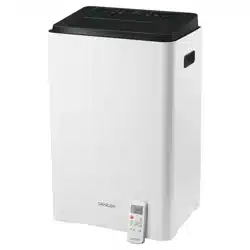
Portable Air Conditioner
User'smanual
■
Prior to using this appliance, please read the user’smanual thoroughly, even in cases, when one has already familiarised themselves with previous use of
similar types of appliances. Only use the appliance in the manner described in this user’smanual. Keep this user’smanual in asafe place where it can be easily
retrieved for future use.
■ We recommend saving the original cardboard box, packaging material, purchase receipt and responsibility statement of the vendor or warranty card for at
least the duration of the legal liability for unsatisfactory performance or quality. In the event of transportation, we recommend that you pack the appliance in
the original box from the manufacturer.
DESCRIPTION OF THE APPLIANCE
A1 Control panel
A2
Automatically-tilting horizontal flaps
A3 Handles (located along both sides)
A4 Remote control sensor
A5 Front cover
A6 Wheels
A7 Top air filter (behind aprotective grille)
A8 Top air inlet
A9 Top drain outlet
A10 Air outlet
A11 Bottom air filter (behind aprotective grille)
A12 Bottom air inlet
A13 Power plug travel compartment
A14 Drain outlet (only on models withapump)
A15 Power cord clip
A16 Power cord outlet
A17 Bottom tank drain hole
DESCRIPTION OF ACCESSORIES
B1 Flexible air exhaust hose
B2 Adapter Afor installation of flexible hose into awall
B3 Flange with plug
B4 Round adapter for connection of flexible hose to air outlet
B5 Drain hose
B6 Window insert with hole
B2 Adapter Bfor installation of flexible hose into awindow
B8 Foam gasket seal
DESCRIPTION OF THE CONTROL PANEL
C1 Automatic shut off indicator
C2 Automatic start indicator
C3 Fan mode indicator
C4 Dehumidification mode indicator
C5 Automatic mode indicator
C6 Cooling mode indicator
C7 LED display
C8 Temperature unit indicator
C9 Power-saving mode indicator (only oncertain models)
C10 Fan speed indicators (low – medium – high)
C11 Sleep function indicator
C12 Power On indicator
C13 SWING button
C14 TIMER button
C15 MODE button
C16 – button
D17 + button
C18 FAN button
C19 SLEEP button
C20 ON/OFF button
REMOTE CONTROL
D1 Display
D2 ON/OFF button
D3 MODE button
D4 FAN button
D5 TEMP button
D6 SLEEP button
D7 SWING button
D8 SHORT CUT button
D9 TIMER ON button
D10 TIMER OFF button
D11 LED button
INSTALLATION
Installation location for the portable air conditioner
Locate the portable air conditioner on an even, dry and stable surface and within reach of agrounded power socket.
To achieve optimal efficiency, maintain adistance of at least 30 cm from the wall or other obstacles.
Note:
Do not use the portable air conditioner to cool aroom where computer servers, etc. are located.
Installation, adjustment, maintenance and repairs must only be performed by aqualified person.
Installation of flexible hose to portable air conditioner
The flexible hose B1 must be connected to the portable air conditioner and installed into awindow / awall in accordance with the operating modes that you
wish to set. Install the flexible hose B1 when you wish to select the operating modes: cooling, dehumidification or automatic mode. It is not necessary to install
the flexible hose B1 when you wish to select the fan mode.
Put the round adapter B4 on to one end of the flexible hose B1 and then attach it to the air outlet A10 so that the tab on the round adapter B4 slides into the
cut-out in the air outlet A10.
On to the free end of the flexible hose attach either adapter Bfor installation of the flexible hose into awindow B7 or adapter Afor installation of the flexible hose
into awall B2.
Installing the flexible hose into aslide window
The window insert with hole B6 is designed to be compatible with the majority of sliding windows (vertical and horizontal). Nevertheless, for certain types of slide
windows it may be necessary to modify the installation procedure described below.
Slide the window sash upwards and place the window insert B6 on to the window sill. Adjust the dimensions of the window insert B6 to the width of the window
(on avertical slide window) / height of the window (on ahorizontal slide window). Secure the set dimension of the window insert B6 using the foam gasket seal
B8. Close the sliding sash all the way on to the window insert B6.
First attach adapter Bfor installation of the flexible hose in awindow B7 on to the free end of the flexible hose. Then stretch out the flexible hose B1 so that it is
possible to attach adapter BB7 to the hole in the window insert B6. Avoid excessive bending of the hose.
Installing the flexible hose into awall
It is important that the installation into awall is performed by aqualified technician.
Drill ahole into the wall with ahole diameter of 125 mm at aheight between 30 cm and 120 cm from floor. Insert the flange with plug B3 into the hole and secure
it to the wall using aset of screws and dowels (these are not included).
Loading ...
Loading ...
Loading ...