
perator's
I:RnFrSMRN°
30 in. Two Bin Rear Bagger
for the Craftsman RERIO00
Model No. 247.24035
\
\\
• Espanol, P. 14
\
/
Before using this equipment,
read this manual and follow
all safety rules and operating
instructions.
For answers to your questions about
this product, Call:
1-800-659-5917
Craftsman Tractor Help Line
7 am = 7 pm CT, Mort. =Sun.
Sears Brands Management Corporation, Hoffman Estates, IL 60179, U.S.A.
Visit our website: www.craftsman.com
FormNo.769-07689
(January2, 2012)

Craftsman One Year Full Warranty
FORONEYEARfrom the dateof purchase,this productis warrantedagainstanydefectsin materialor workmanship.A defectiveproductwill be
replacedfreeof charge.
Forwarrantycoveragedetailsto obtainfree replacement,visit theweb site:www.craftsman.com
Thiswarrantydoesnot coverbags,whichare expendablepartsthat canwear outfromnormalusewithinthe warrantyperiod.
Thiswarrantyis void if thisproductis everusedwhile providingcommercialservicesor if rentedto anotherperson.
Thiswarrantygivesyou specificlegalrights,and you mayalso haveotherrightswhichvary fromstateto state.
Sears Brands Management Corporation, Idoffman Estates, IL 60179
© SearsBrands,LLC 2
Thissymbolpointsout importantsafetyinstructionswhich,if not
followed,couldendangerthepersonalsafetyand/orpropertyof
yourselfandothers. Readand followall instructionsin thismanual
beforeattemptingto operatethismachine.Failureto complywith
theseinstructionsmayresultin personalinjury.Whenyou seethis
symbol,HEEDITSWARNING!
CALIFORNIA PROPOSITION 65
EngineExhaust,someof itsconstituents,andcertainvehicle
componentscontainoremitchemicalsknownto Stateof California
to cause cancerand birthdefects or other reproductiveharm.
Batteryposts,terminals,and relatedaccessoriescontainlead and
leadcompounds,chemicalsknownto the Stateof Californiato
causecancerand reproductiveharm.Washhandsafterhandling.
Thisattachmentwas builtto be usedaccordingto the safeopera-
tion practicesin this manual.Carelessnessor error onthe part of
the operatorcan resultin seriousinjury.Mowersarecapableof
amputatinghandsand feet and throwingobjects.Failureto observe
the followingsafetyinstructionsas wellas the instructionsprovided
withyour mower,could resultin seriousinjuryor death.
Your Responsibility--Restrict the useof thispowermachineto
personswho read,understandand follow thewarningsand instruc-
tionsin this manualandon the machine.
SAVE THESE INSTRUCTIONS!
GENERAL OPERATION
,, Read,understand,and followall instructionson your equipmentand
intheir manualsbeforeattemptingto assembleand operate.Keepthis
manualina safe placefor futureand regularreferenceandfor ordering
replacementparts.
,, Tohelpavoid bladecontact or a thrownobjectinjury,keepbystanders,
helpers,childrenand petsat least 75 feetfrom the mowerwhile it is in
operation.Stop machineif anyoneentersthe area.
,, Thoroughlyinspectthe area wherethe equipmentis to be used.Remove
all stones,sticks, wire, bones, toys,and other foreignobjectswhich
couldbe picked up and thrownby the blade(s).Thrownobjects can
causeseriouspersonalinjury.
,, Alwayswearsafetyglasses or safetygogglesduringoperationand while
performinganadjustmentor repairto protectyoureyes. Thrownobjects
whichricochet can causeseriousinjuryto the eyes.
,, Do not operatethe mowerwithoutthe dischargecoveror entire grass
catcherinits properplace.A missingor damageddischargecoveror
grass bagattachmentcomponentmay result inthrown objectsor blade
contactinjuries.
,, Do not puthands or feet near rotatingparts or underthe cutting deck.
Contactwiththe blade(s) can amputatehandsand feet.
,, Shut off mower'sengineand waitfor bladesto come to a completestop
beforeuncloggingmower'sdischargeopeningor baggerparts.
,, Slow downbeforeturning. Operatethe machinesmoothly.Avoid erratic
operationandexcessivespeed.Be awarethat a grasscatcherattach-
mentcan affectthe handling characteristicsof your mower.
,, Disengageblade(s), set parkingbrake,stopengineand waituntil the
blade(s)cometo a completestop beforeopeningbaggerattachment's
top cover,removinggrass catcher,emptyinggrass,uncloggingchute,
removingany grass ordebris, or makingany adjustments.
,, Neverleave a runningmachineunattended.Alwaysturn offblade(s),
placetransmissionin neutral,set parkingbrake,stop engine andremove
keybeforedismounting.
,, Your machineis designedto cut normalresidentialgrassof a heightno
morethan 10".Do notattemptto mowthrough unusuallytall, dry grass
(e.g.,pasture)or pilesof dry leaves.Drygrass orleaves maycontact
the engineexhaustand/or buildup on the mowerdeckpresentinga
potentialfirehazard.
,, If situationsoccur whichare not coveredinthis manual,use care and
good judgment.Contact 1-800-659-5917for assistance.
3
SLOPE OPERATION
Slopesare a majorfactor relatedto lossof control andtip-overaccidents
whichcan resultinsevere injury or death.Attachmentscan also affect the
stabilityof the machine.All slopesrequireextra caution.
For yoursafety,use the slopegaugeincludedas part of this manualto
estimatetheangle of slopesbeforeoperatingthis machineon a slopedor hilly
area.If theslope is greaterthan 10degreesas shown on the slopeguide,do
notoperatethe mowerwith the grass bagattachmentinstalledonthat area or
seriousinjury could result.
DO:
1. Mowup anddown slopes,not across.Exerciseextremecautionwhen
changingdirectionon slopes.
2. Watchfor holes,ruts,bumps,rocks,or other hiddenobjects. Uneven
terraincouldoverturnthe machine.Tallgrasscan hideobstacles.
3. Useslow speed. Choosea lowenoughspeedsetting sothat you will not
haveto stopor shift whileon the slope.Tires may losetractionon slopes
eventhoughthe brakesarefunctioningproperly.Alwayskeepmachine
in gear when goingdown slopesto takeadvantageof engine braking
action.
4. Followthe manufacturer'srecommendationsfor wheelweightsor
counterweightsto improvestability.
5. Keepall movementon the slopes slow and gradual.Do notmakesud-
denchangesin speedor direction.Rapidengagementor brakingcould
causethe front of the machineto lift and rapidlyflip overbackwards
whichcouldcauseserious injury.
6. Avoidstartingor stoppingon a slope.If tires losetraction,disengagethe
blade(s) andproceedslowly straightdownthe slope.
DO NOT:
1. Do notturn on slopesunlessnecessary;then, turn slowlyand gradually
downhill,if possible.
2. Do notmow near drop-offs,ditchesor embankments.The mowercould
suddenlyturn over if a wheel is overthe edgeof a cliff,ditch,or if an
edge caves in.
3. Do nottry to stabilizethe machineby putting yourfooton theground.
4. Do notuse a grasscatcheron steepslopes.
5. Do notmow on wet grass. Reducedtraction could causesliding.
GENERAL SERVICE
1. Beforecleaning, repairing,or inspecting,makecertainthe blade(s)
and all movingparts havestopped. Disconnectthe spark plugwireand
ground againsttheengine to preventunintendedstarting.
2. Keep all nuts, bolts,and screwstight to be surethe equipmentis in safe
workingcondition.
3. Nevertamperwith yourmower'ssafetyinterlocksystemor othersafety
devices.Checktheir proper operationregularly.
4. Neverattemptto makeadjustmentsor repairswhilethemower'sengine
is running.
5. Grasscatchercomponentsandthe dischargecoverare subjectto wear
and damagewhichcould expose movingpartsor allow objectsto be
thrown.For safetyprotection,frequentlycheck componentsand replace
immediatelywith originalequipmentmanufacturer's(O.E.M.)parts only,
listed inthis manual.Useof parts whichdo not meetthe originalequip-
ment specificationsmay leadto improperperformanceandcompromise
safety!
6. Maintainor replacesafetyand instructionlabels,as necessary.
SAFETY SYMBOLS
This section depicts and describes safety symbols that may appear on this product. Read, understand, and follow all instructions on the machine
before attempting to assemble and operate.
I
I
READTHEOPERATOR'SMANUAL(S)
Read,understand,andfollow all instructionsinthe manual(s)beforeattemptingto assembleand
operate
STOP
Turnoffthe enginebeforeopeningthe baggercover.
4
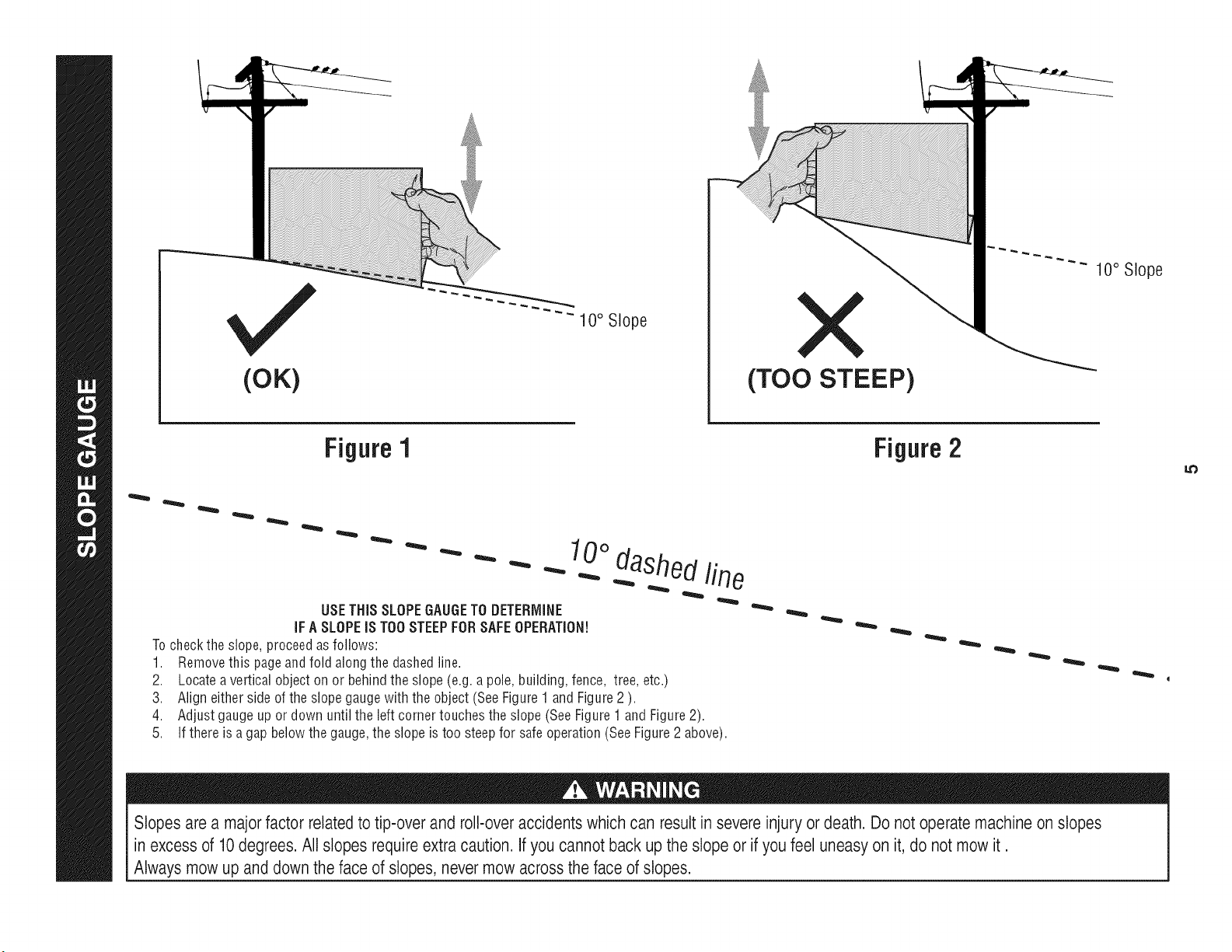
(OK)
10° Slope
(TOO STEEP)
10° Slope
Figure 1
USETHiSSLOPEGAUGETO DETERMINE
iFA SLOPEiS TOOSTEEPFORSAFEOPERATION!
Tocheckthe slope,proceedas follows:
1. Removethis pageandfold alongthe dashedline.
2. Locateavertical objectonor behindthe slope(e.g.a pole,building,fence, tree, etc.)
3. Aligneither sideof the slopegaugewiththe object (SeeFigure1 and Figure2 ).
4. Adjustgaugeup or down until the left cornertouchesthe slope(SeeFigure1 and Figure2).
5.
10odashedline
If there is a gapbelowthe gauge,the slope is too steepfor safeoperation(SeeFigure2 above).
Figure2
Slopes are a majorfactor related to tip-over and roll-over accidents which can result in severe injury or death. Do not operate machine on slopes
in excess of 10degrees. All slopes requireextra caution, if you cannot back up the slope or if you feel uneasy on it, do not mow it.
Always mow up and down the face of slopes, nevermow across the face of slopes.
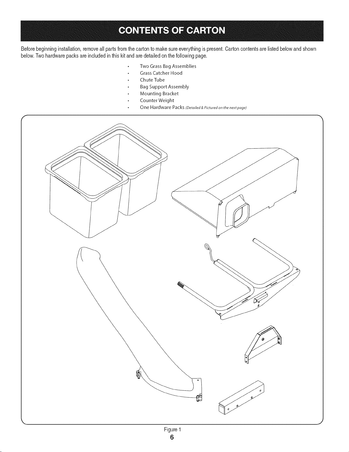
Beforebeginninginstallation,removeall partsfromthe cartonto makesureeverythingis present.Cartoncontentsare listed belowand shown
below.Twohardwarepacksareincludedin thiskit andaredetailedonthe followingpage.
Two Grass Bag Assemblies
Grass Catcher Hood
Chute Tube
Bag Support Assembly
Mounting Bracket
CounterWeight
One Hardware Packs (Detoited&Picturedonthe nextpoge)
Figure1
6
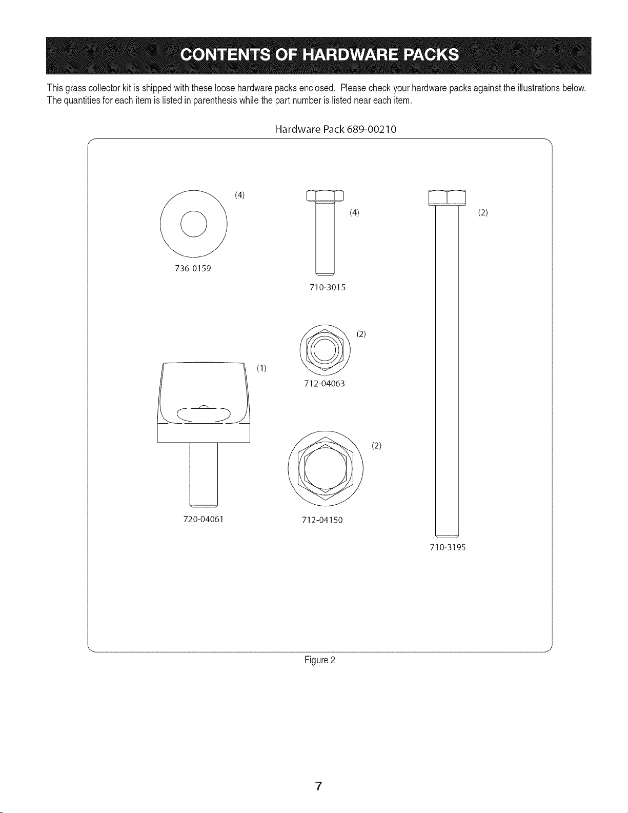
Thisgrasscollectorkit is shippedwith these loosehardwarepacksenclosed, Pleasecheckyourhardwarepacksagainstthe illustrationsbelow,
The quantitiesfor eachitem is listedin parenthesiswhilethe part numberis listedneareach item.
Hardware Pack 689-00210
(4) _ (4)
736-0159
LJ
720-04061
(1)
710-3015
(2)
712-04063
(2)
712-04150
710-3195
(2)
Figure2
7
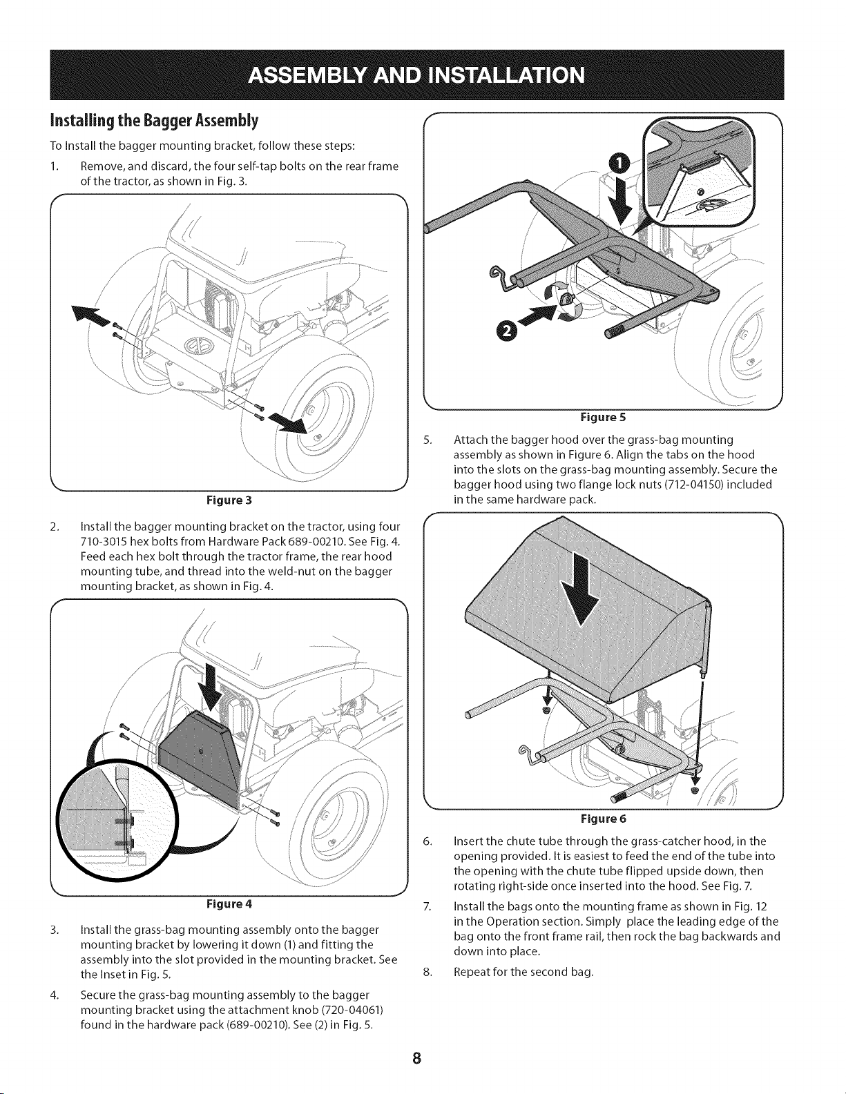
Installingthe BaggerAssembly
To install the bagger mounting bracket, follow these steps:
1. Remove, and discard, the four self-tap bolts on the rear frame
of the tractor, as shown in Fig. 3.
/
/
/
2'
/
/
/
/
Figure 3
5_
Figure 5
Attach the bagger hood over the grass-bag mounting
assembly as shown in Figure 6. Align the tabs on the hood
into the slots on the grass-bag mounting assembly. Secure the
bagger hood using two flange lock nuts (712-04150) included
in the same hardware pack.
2_
Install the bagger mounting bracket on the tractor, using four
710-3015 hex bolts from Hardware Pack 689-00210. See Fig. 4.
Feed each hex bolt through the tractor frame, the rear hood
mounting tube, and thread into the weld-nut on the bagger
mounting bracket, as shown in Fig. 4.
//
Figure 4
3. Install the grass-bag mounting assembly onto the bagger
mounting bracket by lowering it down (1) and fitting the
assembly into the slot provided in the mounting bracket. See
the Inset in Fig. 5.
4. Secure the grass-bag mounting assembly to the bagger
mounting bracket using the attachment knob (720-04061)
found in the hardware pack (689-00210). See (2)in Fig. 5.
Figure 6
6. Insert the chute tube through the grass-catcher hood, in the
opening provided. It is easiest to feed the end of the tube into
the opening with the chute tube flipped upside down, then
rotating right-side once inserted into the hood. See Fig. 7.
7. Install the bags onto the mounting frame as shown in Fig. 12
in the Operation section. Simply place the leading edge of the
bag onto the front frame rail, then rock the bag backwards and
down into place.
8. Repeatforthesecond bag.
8
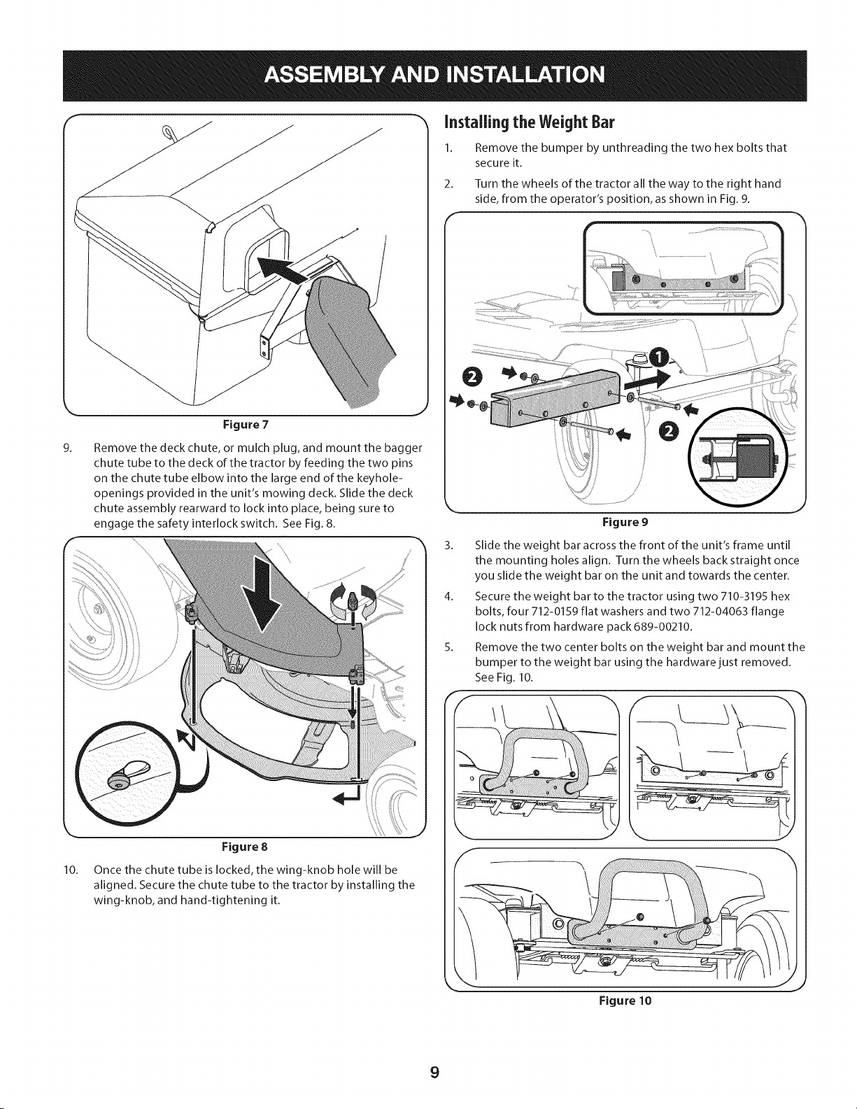
9.
10.
Figure 7
Remove the deck chute, or mulch plug, and mount the bagger
chute tube to the deck of the tractor by feeding the two pins
on the chute tube elbow into the large end of the keyhole-
openings provided in the unit's mowing deck. Slide the deck
chute assembly rearward to lock into place, being sure to
engage the safety interlock switch. See Fig. 8.
\\
J
Figure 8
Once the chute tube is locked, the wing-knob hole will be
aligned. Secure the chute tube to the tractor by installing the
wing-knob, and hand-tightening it.
Installing the Weight Bar
1. Remove the bumper by unthreading the two hex bolts that
secure it.
2. Turn the wheels of the tractor all the way to the right hand
side, from the operator's position, as shown in Fig. 9.
Figure 9
3. Slide the weight bar across the front of the unit's frame until
the mounting holes align. Turn the wheels back straight once
you slide the weight bar on the unit and towards the center.
4. Secure the weight bar to the tractor using two 710-3195 hex
bolts, four 712-0159 flat washers and two 712-04063 flange
lock nuts from hardware pack 689-00210.
5. Remove the two center bolts on the weight bar and mount the
bumper to the weight bar using the hardware just removed.
See Fig. 10.
\
Figure 10
9
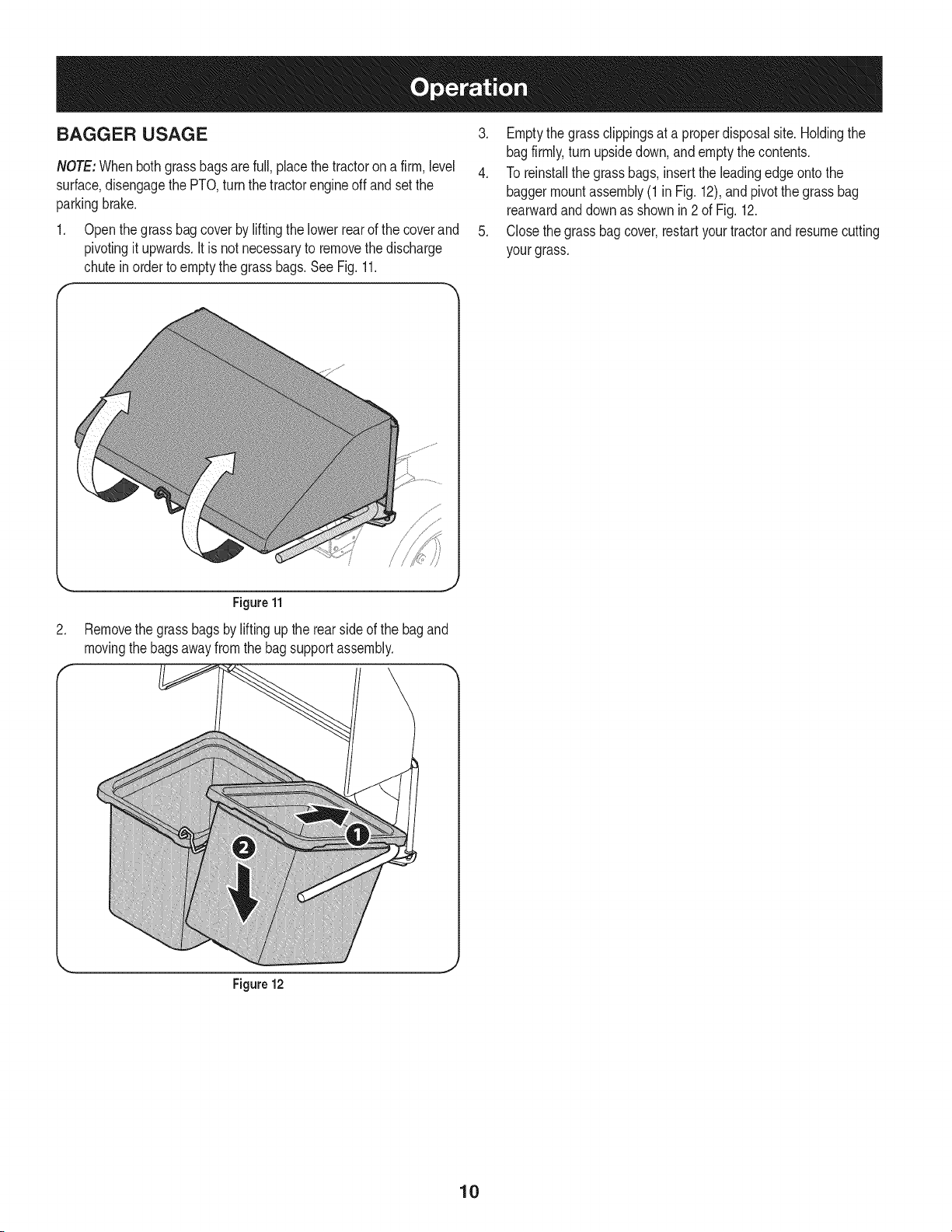
BAGGER USAGE
NOTE:Whenboth grassbagsarefull, placethe tractorona firm, level
surface,disengagethe PTO,turnthe tractorengineoff andsetthe
parkingbrake.
1. Openthe grassbag coverby liftingthe lowerrearof the coverand
pivotingit upwards.It is not necessaryto removethe discharge
chutein order toemptythe grassbags.See Fig.11.
3. Emptythe grassclippingsat a properdisposalsite. Holdingthe
bagfirmly,turn upsidedown,and emptythecontents.
4. To reinstallthe grassbags,insertthe leadingedge ontothe
baggermountassembly(1in Fig.12),andpivotthe grassbag
rearwardand downas shownin2 of Fig. 12.
5. Closethegrassbagcover,restartyourtractorand resumecutting
yourgrass.
Figure 11
2. Removethe grassbagsby liftingup the rearsideof the bag and
movingthebagsawayfromthe bagsupportassembly.
Figure 12
10

This page intentionally left blank. Use this page to make any notes regarding your tractor.
11
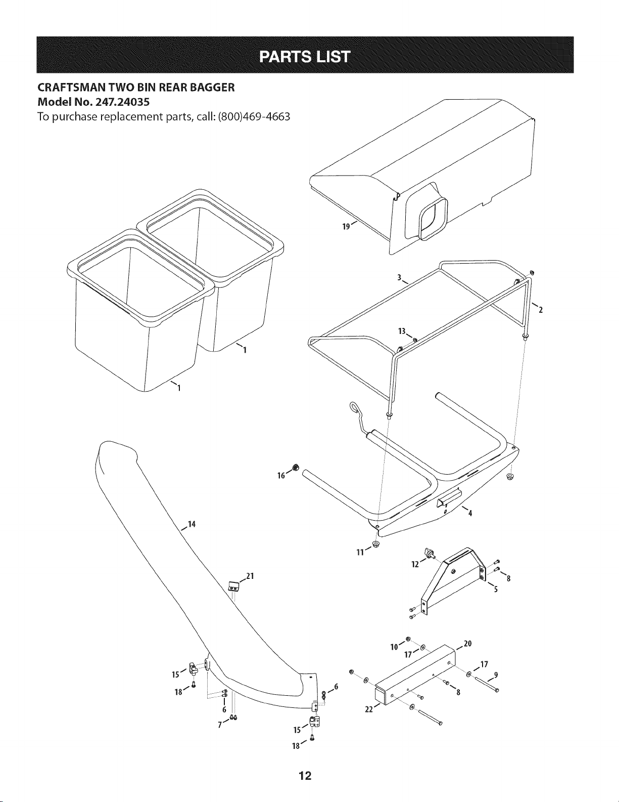
CRAFTSMAN TWO BIN REAR BAGGER
Model No. 247.24035
To purchase replacement parts, call: (800)469-4663
12

!
Ref, I Part Number
1. 664-04167
2. 683-04771
3. 683-04772
4. 683-04775
5. 683-04781
6. 710-0895
Z 710-0599
8. 710-3015
9. 710-3195
lO. 712-04063
II. 712-04150
12. 720-04061
13. 726-0100
14. 731-08548
15. 731-08834
16. 735-0246A
17. 736-0159
18. 738-04519
19. 764-04148
20. 783-07380
21. 783-07286
22. 783-07379
Description
Grass Bag
Front Hood Assembly Frame
Rear Hood Assembly Frame
Bagger Support Assembly
Mounting Bracket
Hex Lock Screw, 1/4-15, 0.75
Tap Screw, 1/4-20, 0.500
Hex Head Screw, 1/4-20, .75
Hex Head Screw, 5/16-18, 4.50
Flange Lock Nut, 5/16-18
Flange Lock Nut, 1/2-13
Knob, 3/8-16, .875
Push Cap, 3/8 ROD
Chute Tube
Chute Mount Bracket
Plug End
Flat Washer, .349 x .879 x .063
Shoulder Screw, 1/4-15, .750
Grass Catcher Hood
Weight Bar Mounting Bracket
Boot Switch Safety Bracket
Weight Bar
13

Garant[a ........................................................................ 14
Medidas importantes de seguridad ............................. 15
Gu_a pendiente de ........................................................ 17
Contenido de la caja y paquetes de hardware ..............18
Montaje e Instalaci6n ................................................... 20
operaci6n de ............................................................... 22
Lista de piezas ............................................................ 12
Craftsman Un ASo De Garantia
Duranteun aSodesdelafechadecompra,esteproductoest&garantizadocontracualquierdefectode materialeso manode obra. Unproducto
defectuososer&reemplazadodeformagratuita.
Forwarrantycoveragedetailsto obtainfree replacement,visit theweb site:www.craftsman.com
Thiswarrantydoesnot coverbags,whichare expendableparts that canwear outfromnormalusewithinthe warrantyperiod.
Thiswarrantyis void if thisproductis everusedwhile providingcommercialservicesor if rentedto anotherperson.
Thiswarrantygivesyou specificlegalrights,andyou mayalso haveotherrights whichvary from stateto state.
Sears Brands Management Corporation, Hoffman Estates, IL 60179
© SearsBrands,LLC 14
Lapresenciadeeste sirnboloindicaque setratade instrucciones
irnportantesde seguridadquese debenrespetarparaevitar
poneren peligrosu seguridadpersonaly/o materialy la de otras
personas.Leay siga todaslas instruccionesdeeste manualantes
de poneren funcionarnientoestarnAquina.Si no respetaestas
instruccionespodria provocarlesionespersonales.Cuandoveaeste
sirnbolo,ipresteatenci6na la advertencia!
PROPOSICION 65 DE CALIFORNIA
Elescapedel motordeeste producto,algunosde suscornponentes
y algunoscornponentesdelvehiculocontieneno liberan sustancias
quirnicasqueel estado de Californiaconsideraque puedenproducir
cancer,defectosde nacirnientouotros problernasreproductivos.
Losbornesdela bateriay los accesoriosalinescontienenplornoy
cornpuestosde plorno,sustanciasquirnicasque seg_nIo estableci-
do porel Estadode Californiacausancancery daSosen el sisterna
reproductivo.Ldveselas manos despu_sde estar en contacto
con estoscomponentes.
EstarnAquinarueconstruidaparaseroperadadeacuerdocon
las reglasde seguridadcontenidasen este manual.AI igualque
concualquiertipo deequipornotorizado,undescuidoo error por
partedeloperadorpuedeproducirlesionesgraves.EstarnAquina
es capazde arnputarrnanosy piesy dearrojarobjetoscon gran
fuerza.Deno respetarlas instruccionesde seguridadsiguientesse
puedenproducirlesionesgraveso larnuerte.
Su responsabilidad--Restrinja el usode esta rnAquina
rnotorizadaa las personasque lean,cornprendany respetenlas
advertenciase instruccionesqueaparecenen este manualy en la
rnAquina.
iGUARDEESTASINSTRUCCIONES!
Fun¢ionamiento general
1. Lea, comprenda y respete todas las instrucciones que figuran
en el equipo yen los manuales antes de intentar armarlo y
hacerlo funcionar. Guarde este manual en un lugar seguro
para consultas futuras y peri6dicas, asi como para solicitar
repuestos.
2. Para ayudar a evitar una lesi6n pot contacto con las cuchillas
o con un objeto que sea arrojado, mantenga alas personas
que observan, a los ayudantes, ni_os y mascotas alejados a no
menos de 25 metros de la m_quina mientras est& funcionando.
Detenga la m&quina si alguien entra en la zona.
3. Revise minuciosamente el _irea donde se va a usar el equipo.
Retire todas las piedras, palos, cables, huesos, juguetes y otros
objetos extra6os que podrian set recogidos y arrojados por la
acci6n de las cuchillas. Los objetos arrojados por la m&quina
pueden causar lesiones graves.
4. Para protegerse los ojos, utilice siempre galas o lentes de
seguridad mientras opera la m&quina o mientras la ajusta
o repara. Los objetos arrojados que rebotan pueden causar
lesiones oculares graves.
5. Nunca opere la cortadora de c_sped sin tenet bien colocada
la cubierta de descarga o el colector de c_sped. Si falta o
est_ da6ada la cubierta de descarga oun componente del
accesorio embolsador puede resultar en lesiones por contacto
con la cuchilla o con objetos arrojados.
6. No ponga las manos ni los pies cerca de las piezas rotatorias ni
debajo de la plataforma de corte. El contacto con las cuchillas
puede resultar en la amputaci6n de una mano o pie.
7. Apague el motor de la cortadora de c_sped y espere que
las cuchillas se detengan totalmente antes de desbloquear
la abertura de descarga de la cortadora o las piezas de la
embolsadora.
8. Reduzca la velocidad antes de girar. Opere la m&quina de
forma pareja. Evite el funcionamiento err_itico y la velocidad
excesiva. Tenga en cuenta que el accesorio colector de c_sped
puede afectar las caracteristicas de manejo de su cortadora.
Fundonamiento en pendientes
Las pendientes son un factor importante en los accidentes
ocasionados pot p_rdida de control y vuelcos que pueden causar
lesiones graves e incluso la muerte. Los accesorios tambien pueden
afectar la estabilidad de la m&quina. La operaci6n en pendiente
requiere mayor precauci6n.
Para seguridad, use el medidor de pendientes que se incluye como
parte de este manual para estimar el _ingulo de la pendiente antes
de hacer funcionar la m_iquina en una zona inclinada. Si la pendiente
es mayor a 10 grados en el medidor, no opere la cortadora con el
accesorio embolsador en ese sector, pues podria causar lesiones
graves.
HagaIo siguiente:
1. Corte hacia arriba y abajo de las pendientes, no en forma
transversal. Tenga sumo cuidado al cambiar de direcci6n en
una pendiente.
2. Est_ atento a los hoyos, surcos, baches, rocas, u otros objetos
ocultos. El terreno desnivelado puede voltear la m&quina. El
pasto alto puede ocultar obst_iculos.
3. Conduzca a baja velocidad. Elija una velocidad Io
suficientemente baja como para no tener que detenerse
o cambiar de marcha mientras est,1 en la pendiente. Los
neum_ticos pueden perder tracci6n en las pendientes aun
cuando los frenos funcionen correctamente. Mantenga
la m&quina siempre en velocidad cuando desciende una
pendiente, para poder frenar con el motor.
15
4. Siga las recomendaciones del fabricante sobre pesos y
contrapesos de las ruedas, para mejorar la estabilidad.
5. Haga que todos los movimientos en las pendientes sean
lentos y graduales. No cambie repentinamente la velocidad
ni la direcci6n. Un frenado o cambio de velocidad repentinos
pueden causar que el frente de la m_quina se levante y d6 una
voltereta hacia atr_s, Io que podria causar lesiones graves.
6. Evite arrancar o detenerse en una pendiente. Silos neum_ticos
pierden tracci6n, desenganche las cuchillas y descienda
lentamente la pendiente.
No haga I0siguiente:
I. No gire en una pendiente a menos que sea imprescindible. De
ser posible, gire lenta y gradualmente cuesta abajo.
2. No corte el c_sped cerca de barrancos, zanjas o terraplenes. La
cortadora de c_sped podria volcarse repentinamente si una de
las ruedas estuviera sobre el borde de un acantilado o zanja, o
si un borde se desmoronara.
3. No intente estabilizar la m_quina poniendo el pie en el suelo.
4. No utilice un colector de c_sped en pendientes empinadas.
5. No corte el c_sped humedo. Una reducci6n en tracci6n puede
causar derrapes.
Servid0 general
I. Antes de limpiar, reparar o inspeccionar la m_quina,
compruebe que las cuchillas y todas las piezas m6viles se
hayan detenido. Desconecte el cable de la bujia y p6ngalo
haciendo masa contra el motor para evitar que arranque
accidentalmente.
2. Mantenga todas las tuercas, pernos y tornillos bien ajustados
para asegurarse de que el equipo est_ en condiciones seguras
de operaci6n.
3. Nunca intente violar el sistema de bloqueo de seguridad u
otros mecanismos de seguridad de la cortadora. Controle
peri6dicamente que funcionan correctamente.
4. No intente nunca hacer ajustes o reparaciones a la cortadora
mientras el motor est_ en marcha.
5. Los componentes del colector de c6sped y la cubierta de
descarga est_n sujetos a desgaste y daffos que podrian dejar
expuestas piezas que se mueven o permitir que se arrojen
objetos. Para proteger su seguridad, verifique frecuentemente
todos los componentes y reempl_celos inmediatamente
0nicamente con piezas de los fabricantes del equipo original
(O.E.M.) indicados en este manual. El uso de piezas que no
cumplen con las especificaciones del equipo original puede
resultar en rendimiento inadecuado y puede poner en peligro
la seguridad.
6. Mantenga o reemplace las etiquetas de seguridad y de
instrucciones seg0n sea necesario.
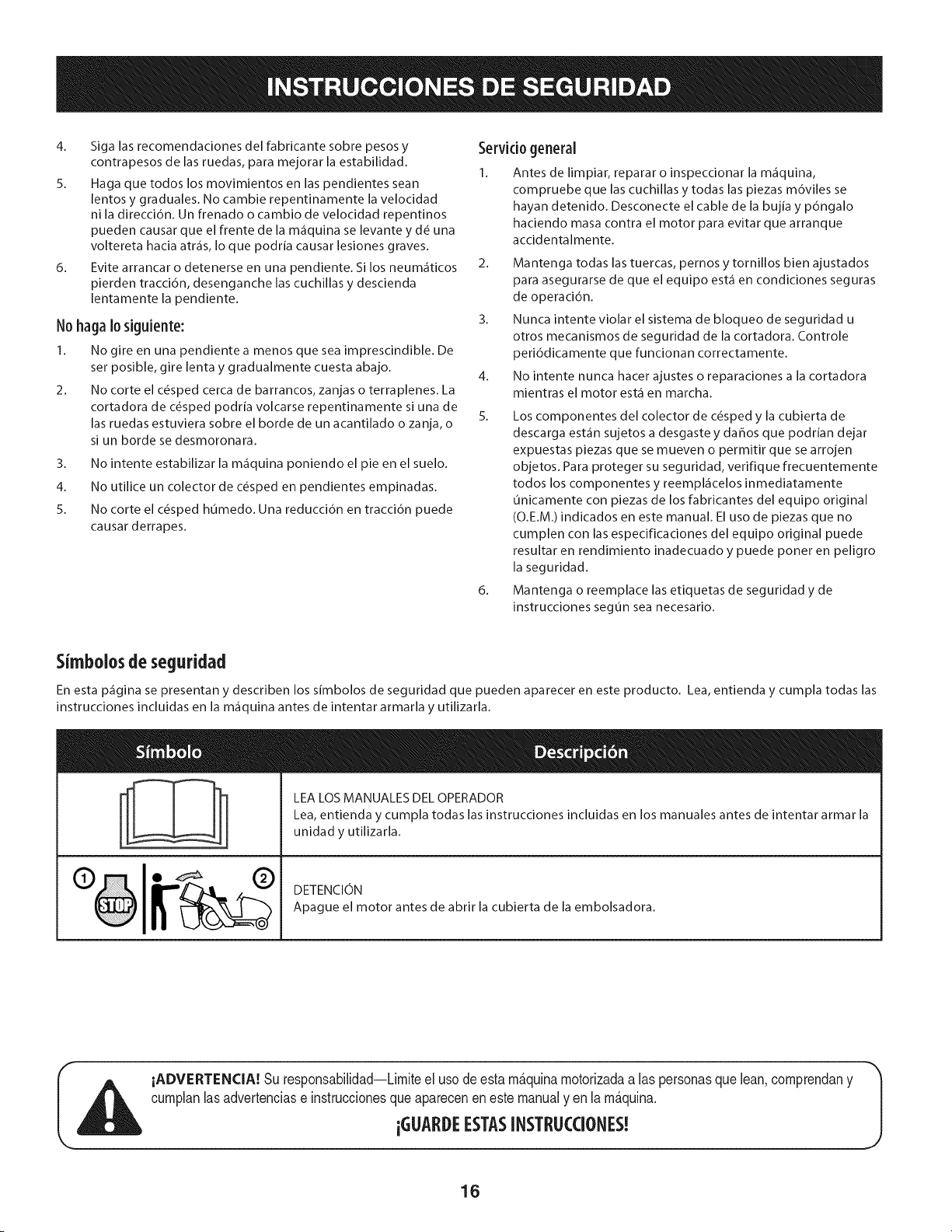
Simbolosde segufidad
En esta p_gina se presentan y describen los simbolos de seguridad que pueden aparecer en este producto. Lea, entienda y cumpla todas las
instrucciones incluidas en la m_quina antes de intentar armarla y utilizarla.
LEA LOS MANUALES DEL OPERADOR
Lea, entienda y cumpla todas las instrucciones incluidas en los manuales antes de intentar armar la
unidad y utilizarla.
DETENCION
Apague el motor antes de abrir la cubierta de la embolsadora.
iADVERTENCIA! Su responsabilidad--Limiteel usode esta m_.quinamotorizadaalas personasque lean,comprendany
cumplanlasadvertenciase instruccionesqueaparecenen este manualyen la m_.quina.
iGLIARDEESTASINSTRL!CCIONES!
16
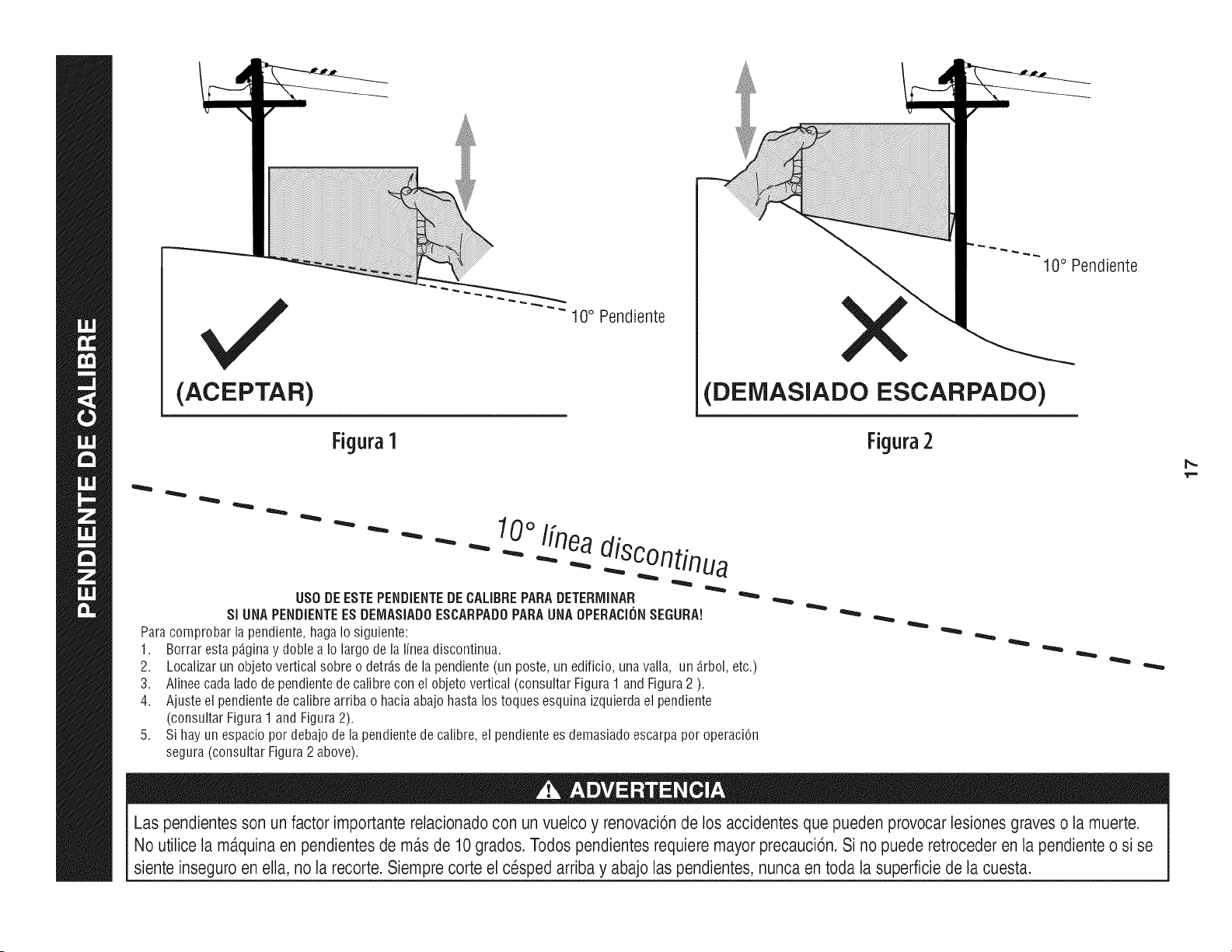
(ACEPTAR)
Figura1
"" 10 ° Pendiente
10° Pendiente
(DEiVIASlADO ESCARPADO)
Figura2
0oI[nea
- - " "" - _ .-...diSC°ntinua
US0 DEESTEPENDIENTEDECALIBREPARADETERiVIINAR
SI UNAPENDiENTEESDEIV1ASiADOESCARPADOPARAUNAOPERACi(_NSEGURA!
Paracomprobarlapendiente,hagaIosiguiente:
1. Borrarestap_.ginay doblea Io largode la lineadiscontinua.
2.
3.
4.
Localizarun objetoverticalsobreo detrJ.sdelapendiente(un poste,un edificio,unavalla, un _.rbol,etc.)
Alineecadaladode pendientede calibrecon elobjetovertical(consultarFigura1 andFigura2 ).
Ajusteel pendientede calibrearriba o haciaabajohastalos toquesesquinaizquierdael pendiente
(consultarFigura1andFigura2).
Sihayun espaciopordebajodela pendientedecalibre,el pendientees demasiadoescarpaporoperaciOn
segura(consultarFigura2 above).
Las pendientesson un factor importante relacionadocon un vuelco y renovaci6nde los accidentes que pueden provocar lesiones graves o la muerte.
No utilice la m_.quinaen pendientes de m_.sde 10grados. Todos pendientesrequiere mayor precauci6n. Si no puede retroceder en la pendiente o si se
siente inseguro en ella, no la recorte. Siempre corte el cesped arriba y abajo laspendientes, nunca en toda la superficie de la cuesta.
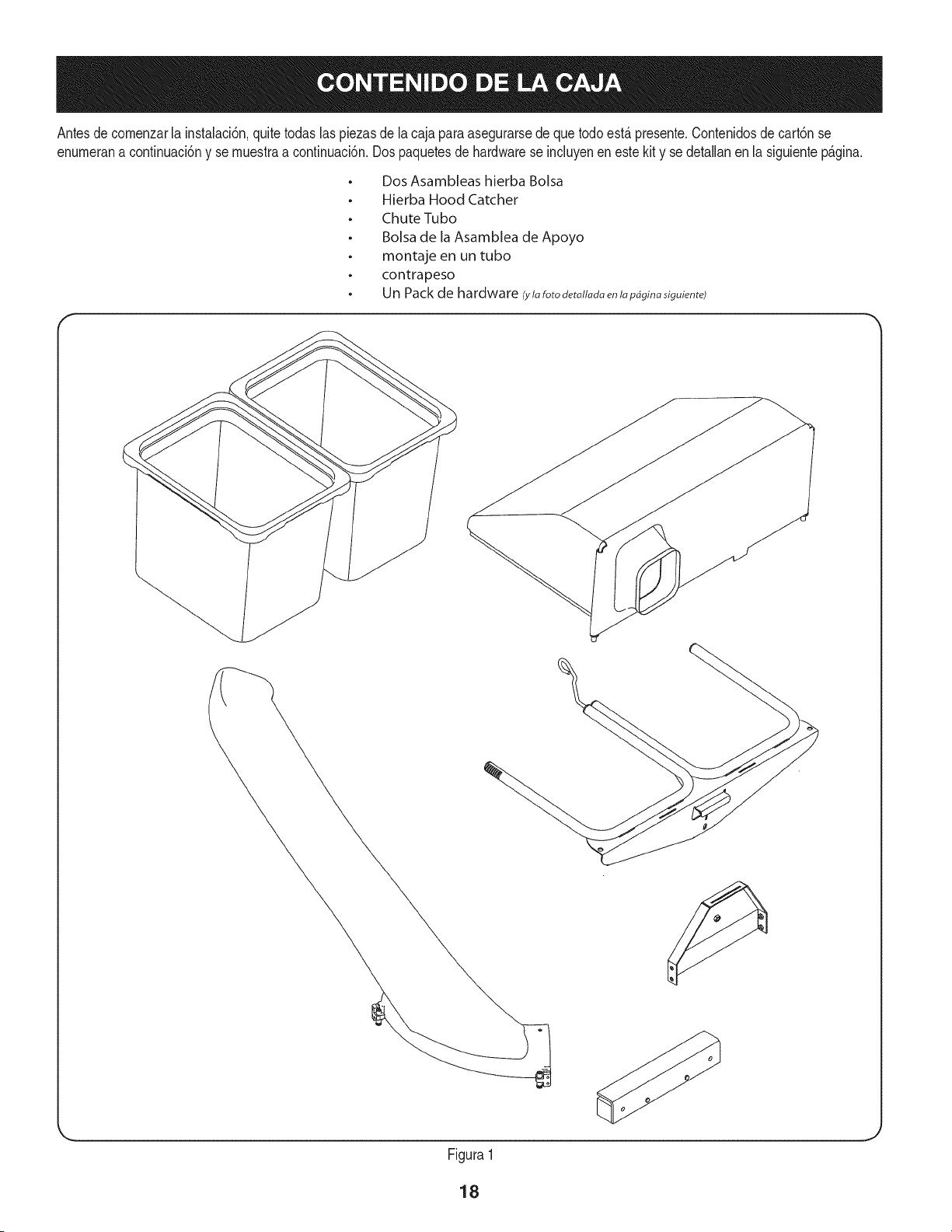
Antesde comenzarla instalaci6n,quitetodaslas piezasde lacaja paraasegurarsede que todoest,. presente.Contenidosde cart6nse
enumerana continuaci6ny se muestraa continuaci6n.Dospaquetesde hardwarese incluyenenestekity se detallanen la siguientep_.gina.
o
o
o
o
o
o
Dos Asambleas hierba Bolsa
Hierba Hood Catcher
Chute Tubo
Bolsa de la Asamblea de Apoyo
montaje en un tubo
contrapeso
Un Pack de hardware (ylafotodetatladaenlapbginasiguiente)
Figura1
18
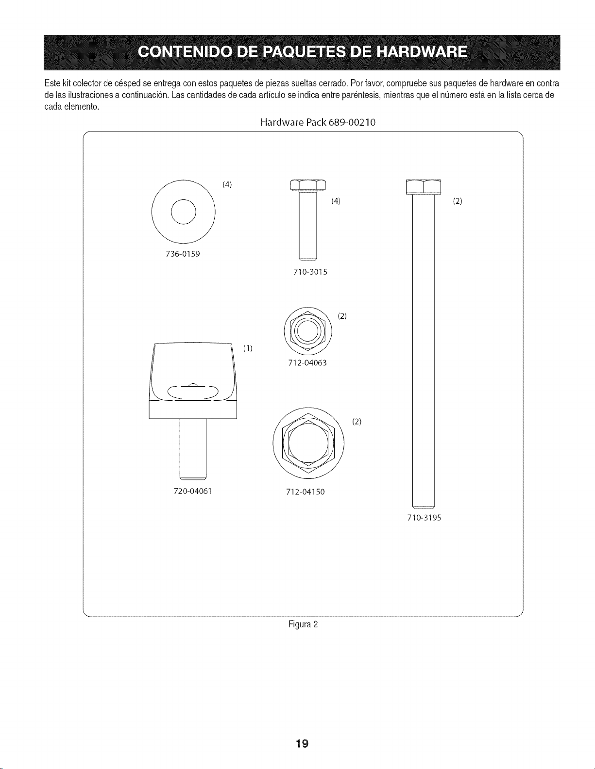
Estekit colectorde c_spedse entregacon estospaquetesdepiezassueltascerrado.Porfavor,compruebesus paquetesde hardwareen contra
de las ilustracionesa continuaci6n.Lascantidadesde cadaarticulo seindicaentre par_ntesis,mientrasqueel nQmeroest,.en la lista cercade
cada eiemento.
Hardware Pack 689-00210
(4) _ (4)
736-0159
720-04061
(1)
710-3015
(2)
712-04063
(2)
712-04150
710-3195
(2)
Figura2
19
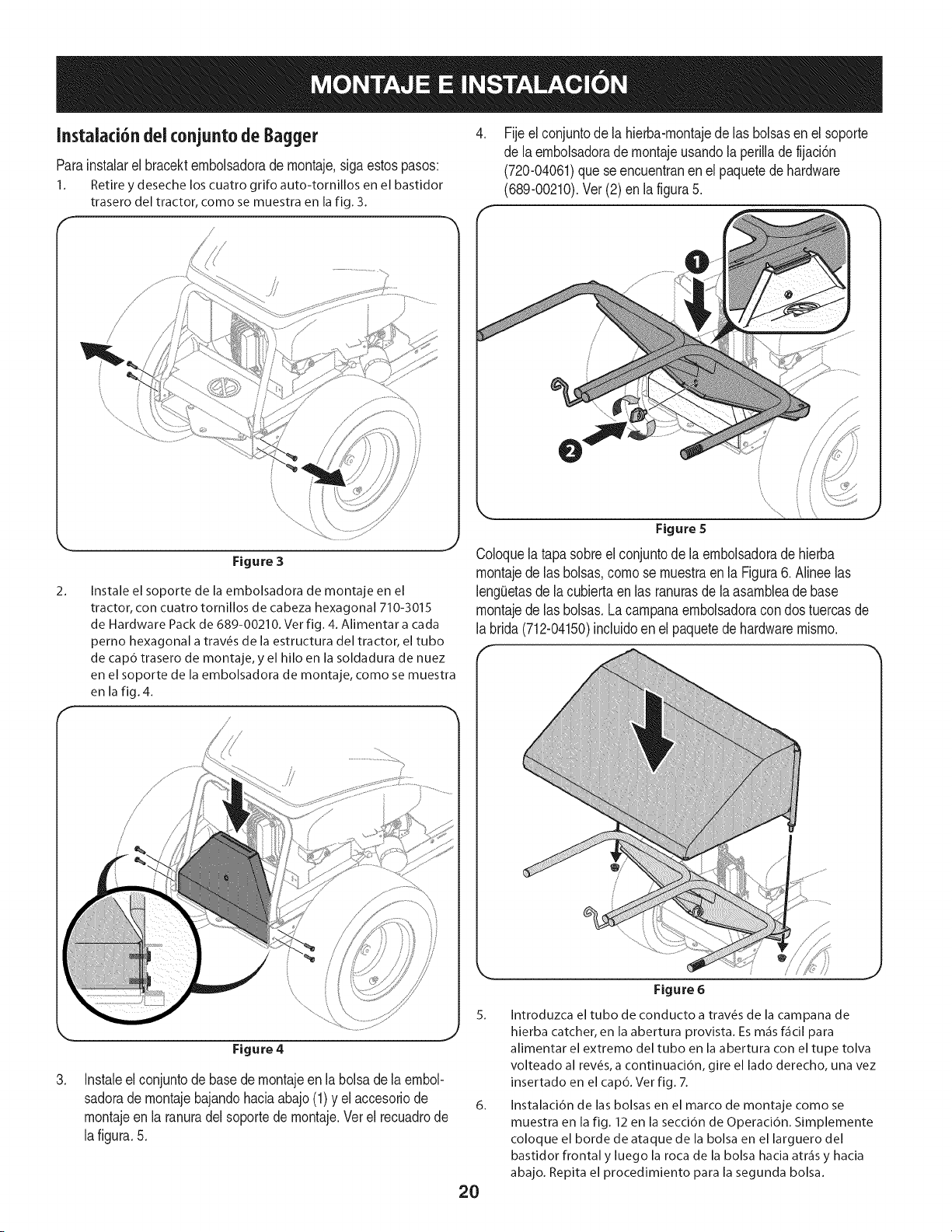
Instalaci6ndeiconjunto deBagger
Parainstalarel bracektembolsadorade montaje,siga estospasos:
1. Retire y deseche los cuatro grifo auto-tornillos en el bastidor
trasero del tractor, como se muestra en la fig. 3.
,
Fijeel conjuntode la hierba-montajede las bolsasenel soporte
de laembolsadorade montajeusandola perillade fijaci6n
(720-04061)que seencuentranenel paquetede hardware
(689-00210).Ver (2) en la figura5.
2_
\
Figure 3
Instale el soporte de la embolsadora de montaje en el
tractor, con cuatro tornillos de cabeza hexagonal 710-3015
de Hardware Pack de 689-00210. Ver fig. 4. Alimentar a carla
perno hexagonal a trav6s de la estructura del tractor, el tubo
de cap6 trasero de montaje, y el hilo en la soldadura de nuez
en el soporte de la embolsadora de montaje, como se muestra
en la fig. 4.
Coloquela tapasobreel conjuntode laembolsadoradehierba
montajede las bolsas,como se muestraen la Figura6. Alineelas
leng0etasde lacubiertaen las ranurasdela asambleade base
montajede las bolsas.Lacampanaembolsadoracon dos tuercasde
la brida(712-04150)incluidoenel paquetede hardwaremismo.
,
Figure 4
Instaleel conjuntodebasede rnontajeen la bolsadela embol-
sadorade montajebajandohaciaabajo(1) y el accesoriode
montajeen la ranuradelsoportede montaje.Verel recuadrode
lafigura.5.
5. Introduzca el tubo de conducto a trav6s de la campana de
hierba catcher, en la abertura provista. Es m_is f_icil para
alimentar el extremo del tubo en la abertura con el tupe tolva
volteado al rev6s, a continuaci6n, gire el lado derecho, una vez
insertado en el cap6. Ver fig. 7.
6. Instalaci6n de las bolsas en el marco de montaje como se
muestra en la fig. 12 en la secci6n de Operaci6n. Simplemente
coloque el borde deataque de la bolsa en el larguero del
bastidor frontal y luego la roca de la bolsa hacia atr_is y hacia
abajo. Repita el procedimiento para la segunda bolsa.
Figure 6
20

7.
.J
Figura 7
Retireel conductodela cubierta,o clavijade abono,y colocar
el tubodelconductode Baggera lacubiertadel tractorpor la
alimentaci6nde los dos pernosen el codo deltubo rampaenel
extremograndede lacerradurade las aberturasexistentesen la
plataformade corte de la unidad.Desliceel canalde la cubierta
traserademontajepara bloquearen su lugar,asegur_.ndosede
activarel interruptorde seguridad.Vet fig.8.
\
Instalaci6n de ia barra de peso
1. Retireel topedesenroscandolos dos tornilloshexagonalesque
Io sujetan.
2. Girarlas ruedasdel tractor,todoel caminohastael lado derecho,
desdela posici6ndeloperador,comose muestraen la fig. 9.
\
Figura 9
3. Deslicelabarra de pesoa travesde la partedelanteradel marco
de launidadhasta que losorificiosde montajeest_nalineados.
Girarlas ruedasespaldarecta,una vez que deslice la barra de
pesode launidady haciaelcentro.
4. Asegurela barrade pesoenel tractorcon dos tornillosde cabeza
hexagonal710-3195,712-0159cuatroarandelasplanasy dos
tuercasde fijaci6n712-04063bridade hardwarepack689-00210.
5. Retirelos dostornillosdel centrode la barrade pesoy montarel
parachoquesde labarra de peso utilizandoelhardwareacabade
quitar.Verfig. 10.
Una vez que el tubo de conducto est& bloqueado, el agujero
del ala-mando se ajustar,:in. Asegure el tubo de conducto para
el tractor mediante la instalaci6n de la ala-mando, y la mano de
apriete.
Figura 10
21
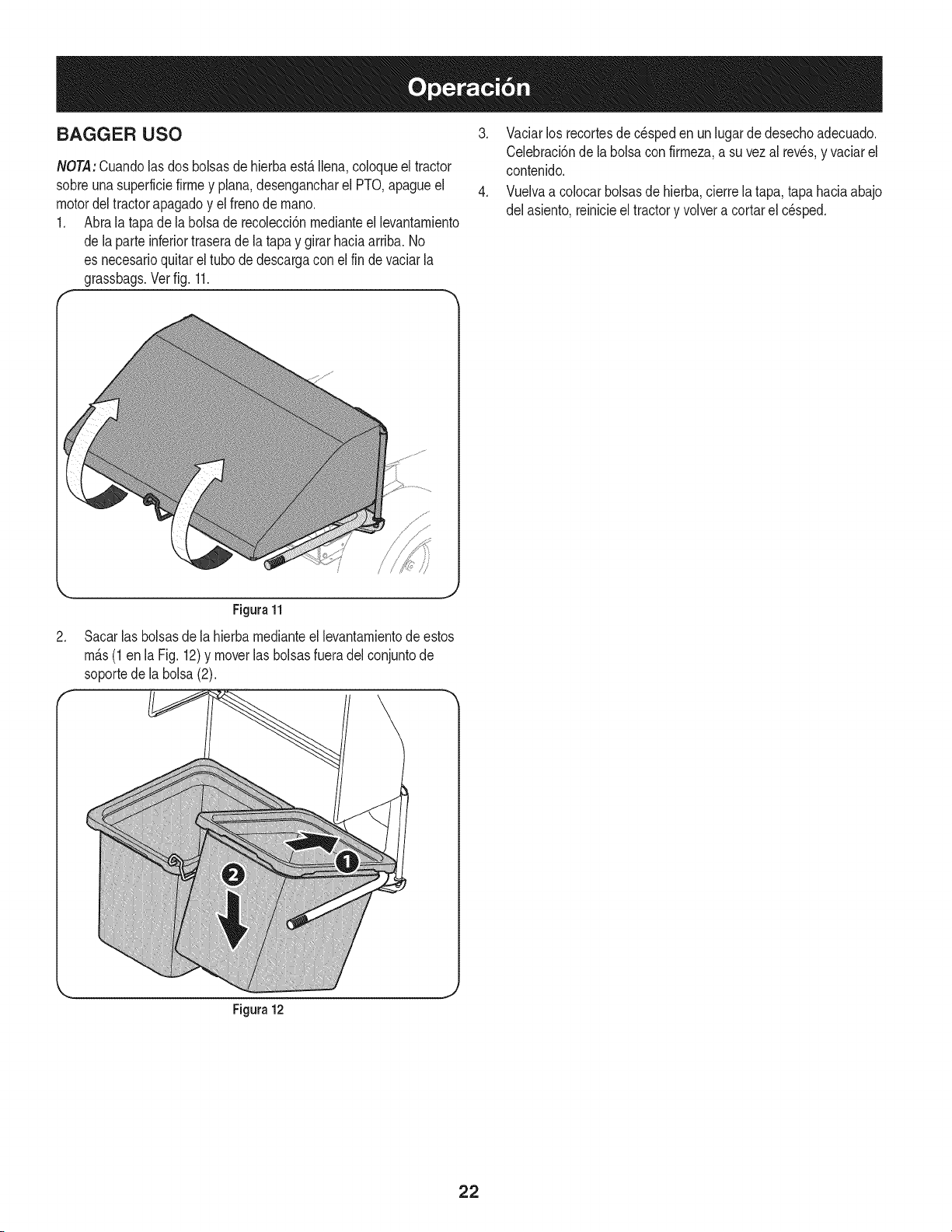
BAGGER USO
NOTA:Cuandolas dosbolsasde hierbaest,. llena,coloqueel tractor
sobreunasuperfMefirmey plana,desengancharel PTO,@agueel
motordeltractorapagadoy el frenode mano.
1. Abralatapa dela bolsade recolecd6nmedianteel levantamiento
de laparte inferiortraserade la tapay girarhaciaarriba. No
es necesarioquitarel tubode descargacon elfin de vaciarla
grassbags.Verfig. 11.
r
3. Vaciarlos recortesde c_speden un lugar de desechoadecuado.
Celebraci6nde labolsacon firmeza,asu vezal reves,y vaciarel
contenido.
4. Vuelvaa colocarbolsasde hierba,cierrela tapa, tapa haciaabajo
del asiento,reinicieel tractory volvera cortarel cesped.
2.
Figura 11
Sacarlas bolsasdela hierbamedianteel levantamientode estos
m_.s(1 en la Fig. 12)y moverlas bolsasfueradel conjuntode
soportede labolsa(2).
Figura 12
22

Esta pagina se dej6 intencionalmente en blanco. Utilice esta pagina para tomar notas acerca de su tractor.
23

Your Home
For troubleshooting, product manuals and expert advice:
managernylife
www.managemylife.com
For repair - in your home - of all major brand appliances,
lawn and garden equipment, or heating and cooling systems,
no matter who made it, no matter who sold it!
For the replacement parts, accessories and
owner's manuals that you need to do-it-yourself.
For Sears professional installation of home appliances
and items like garage door openers and water heaters.
1-800-4-MY-HOME ® (1-800-469-4663)
Call anytime, day or night (U.S.A. and Canada)
www.sears.com www.sears.ca
Our Home
For repair of carry-in items like vacuums, lawn equipment,
and electronics, call anytime for the location of your nearest
Sears Parts & Repair Service Center
1-800-488-1222 (U.S.A.) 1-800-469-4663 (Canada)
www.sears.com www.sears.ca
To purchase a protection agreement on a product serviced by Sears:
1-800-827-6655 (U.S.A.) 1-800-361-6665 (Canada)
Para pedir servicio de reparaci6n
a domicilio, y para ordenar piezas:
1-888-SU-HOGAR ®
(1-888-784-6427)
www.sears.com
Au Canada pour service en frangais:
1-800-LE-FOYER Mc
(1-800-533-6937)
www.sears.ca
® Registered Trademark / TMTrademark of KCD IP, LLC in the United States, or Sears Brands, LLC in other countries
® Marca Registrada ! TMMarca de Fabrica de KCD IP, LLC en Estados Unidos, o Sears Brands, LLC in otros paises
MCMarque de commerce ! MDMarque deposee de Sears Brands, LLC