
Loading ...
Loading ...
Loading ...
INSTALLATION INSTRUCTIONS
INSTALL THE RANGE
(9) ANTI-TIP DEVICE INSTALLATION
WARNING
Tip-Over Hazard
• A child or adult can tip the range and be killed.
• Install the anti-tip bracket to the wall or fl oor.
• Engage the range to the anti-tip bracket by sliding the range back so the anti-tip
arm slides under the anti-tip bracket.
• Re-engage the anti-tip bracket if the range is moved.
• Failure to do so can result in death or serious burns to children or adults.
To reduce the RISK OF TIPPING the range, the range must be secured by a properly installed ANTI-TIP BRACKET.
Secure the bracket with the screws provided. See installation instructions for complete details before attempting to install.
NOTE: The installation of the ANTI-TIP bracket must meet all local codes for securing the appliance.
STEP 1 LOCATE THE BRACKET
IMPORTANT:
Determine the fi nal location of the range before attempting to install the
bracket.
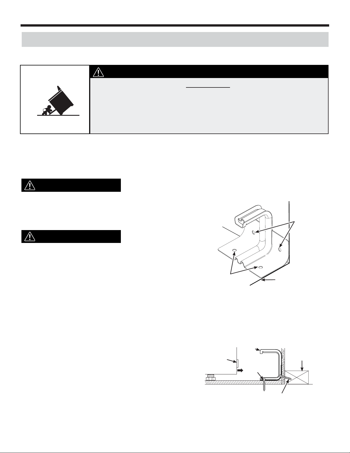
Place the bracket on the fl oor with the back edge against
the rear wall. If the range does not reach the rear wall,
align the back edge of the bracket with the rear panel of
the range in its fi nal location.
Rear Wall
Adjacent cabinet or
nal location of right
range side panel
Loc. A
Loc. B
Two screws must enter oor
or wall at Loc. A or B.
IMPORTANT:
If the bracket does not touch the rear wall, you MUST
screw the bracket to the FLOOR as described in Step 2.
Position the side of the bracket against the right cabinet. If
there is no adjacent cabinet, align the edge of the bracket
with the right side panel of the range in its fi nal location. If
the countertop overhangs the cabinet, offset the bracket
from the cabinet by the amount of the overhang.
A
B
Mark the location for the pair of holes to be used (see illustration above).
NOTE: For FLOOR installation use Loc. A. For REAR WALL installation use Loc. B.
C
STEP 2 SECURE THE BRACKET
Screw must
enter wood
or concrete
Attachment to Floor or Rear Wall
Wall sill plate
Screw must enter wood
Bracket
Anti-tip
arm
The bracket must be screwed to either the FLOOR or the REAR
WALL.
FLOOR Installation
WOOD FLOOR: Use the screws provided to secure the bracket
using the pair of marked holes (Loc. A).
CONCRETE FLOOR: Using a concrete bit, drill a 5/32” pilot hole
2” deep into the concrete at the center of each of the marked holes
(Loc. A). Use the screws provided to secure the bracket into the
fl oor.
22
REAR WALL Installation
Use the 2 screws provided to secure the bracket using the pair of marked holes at Loc. B. The screws MUST enter into a
wood sill plate. If the wall contains any metal studs or similar materials, then the fl oor must be used.
Loading ...
Loading ...
Loading ...