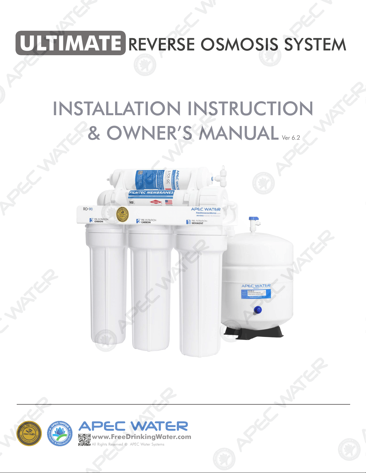
ULTIMATE REVERSE OSMOSIS SYSTEM
INSTALLATION INSTRUCTION
& OWNER’S MANUAL
All Rights Reserved © APEC Water Systems
www.FreeDrinkingWater
.com
Ver 6.2

TABLE OF CONTENT
1. Installation:
Preparation ................................................................................. page 1
Filter housings assembly ............................................................... page 4
Feed water connection .................................................................. page 5
Drain saddle connection .............................................................. page 9
Faucet mounting ......................................................................... page 11
Connecting the system ................................................................ page 14
2. Maintenance:
Filter change schedule & instructions .......................................... page 19
3. Owner’s Manual - RO Basics:
System flow diagram .................................................................. page 24
Input water pressure: most important factor ................................ page 25
Tank volume & delivery pressure ................................................. page 25-26
Misc. topics ................................................................................. page 26
4. Trouble-shoot Guide:
RO Head diagram ....................................................................... page 28
Air bubbles ................................................................................. page 29
No water at dispensing faucet ...................................................... page 29
Slow output ................................................................................. page 30
Filter housing is leaking ............................................................... page 30
TDS (Total Dissolved Solids) Level Reads Higher Than Normal ....... page 31
There is a leak at the tank ball valve connection .......................... page 32
System shut off is abnormal ......................................................... page 32
How to Test RO’s Shut-Off Function .............................................. page 33
Pure water still tastes like tap water ............................................. page 33
RO Makes Humming Noise .......................................................... page 34
5. Other Information:
AirGap Faucet Installation .......................................................... page 36
6. Warranty ....................................................................................... page 38
Please keep this Owner’s Manual for future reference.
It contains useful information on how to maintain and care for your
APEC Reverse Osmosis water filter system.
1
Thank you for choosing APEC reverse osmosis systems.
You now own the finest water filter in America.
Please read and become familiar with instructions and parts needed before proceeding with the in-
stallation.
BEFORE INSTALLATION:
Inspect the system:
Please take the system and all the components out of the box. Inspect the system and all the connection
fittings carefully, make sure nothing is damaged during shipping. If any part is cracked or broken, please
do not proceed with the installation and contact APEC or your distributor for an exchange or diagnosis.
Recommended tools list:
• Variable speed drill
• Drill bit: 1/4” (for the drain line), 1/8” (as pilot, not mandatory), and 1/2” (for standard faucet
hole, air-gap faucet requires 1”d hole)
• 5/8”, 9/16” open-end wrench, or adjustable wrench, pliers
• Phillips screwdriver
• Utility knife, or scissors
• Teflon tape
Operating Parameter
• Operating pressure: 85psi maximum
• Feed water temperature: 40 – 100 °F (4-37 °C)
• Feed water TDS level: 2000ppm maximum
• Do not connect this unit to hot water source
• Install the RO in a sheltered environment, avoid exposure to hot and cold weather or under direct
sunlight.
General Installation/Operation/Maintenance Requirements
• Installation needs to comply with state and local laws and regulations.
• System must be installed indoor away from possible environmental damage
• Do not use with water that is microbiologically unsafe or of unknown quality without adequate
disinfection before or after system. Systems certified for cyst reduction may be used on disinfected
water that may contain filterable cysts.
• This reverse osmosis system contains a replaceable treatment component critical for effective re-
duction of total dissolved solids. The product water shall be tested periodically to verify that system
is performing satisfactorily.
Important! Please TURN OFF the main cold water supply to the RO system when the unit is not in use dur-
ing a vacation or extended leave. During very cold or freezing weather conditions, please also TURN OFF
the main cold water supply and completely drain all of the water from the RO system and water storage
tank.
Copyright:
This manual is copyrighted by APEC Inc. Under the copyright laws, this manual may not be reproduced in any form, in whole or
part, without the prior written consent of APEC Inc. Manual print ver. 6.2, 2020 Feb.
2
1 Faucet with tubing,
washers and nuts
(Faucet color may vary,
depends on the color selected)
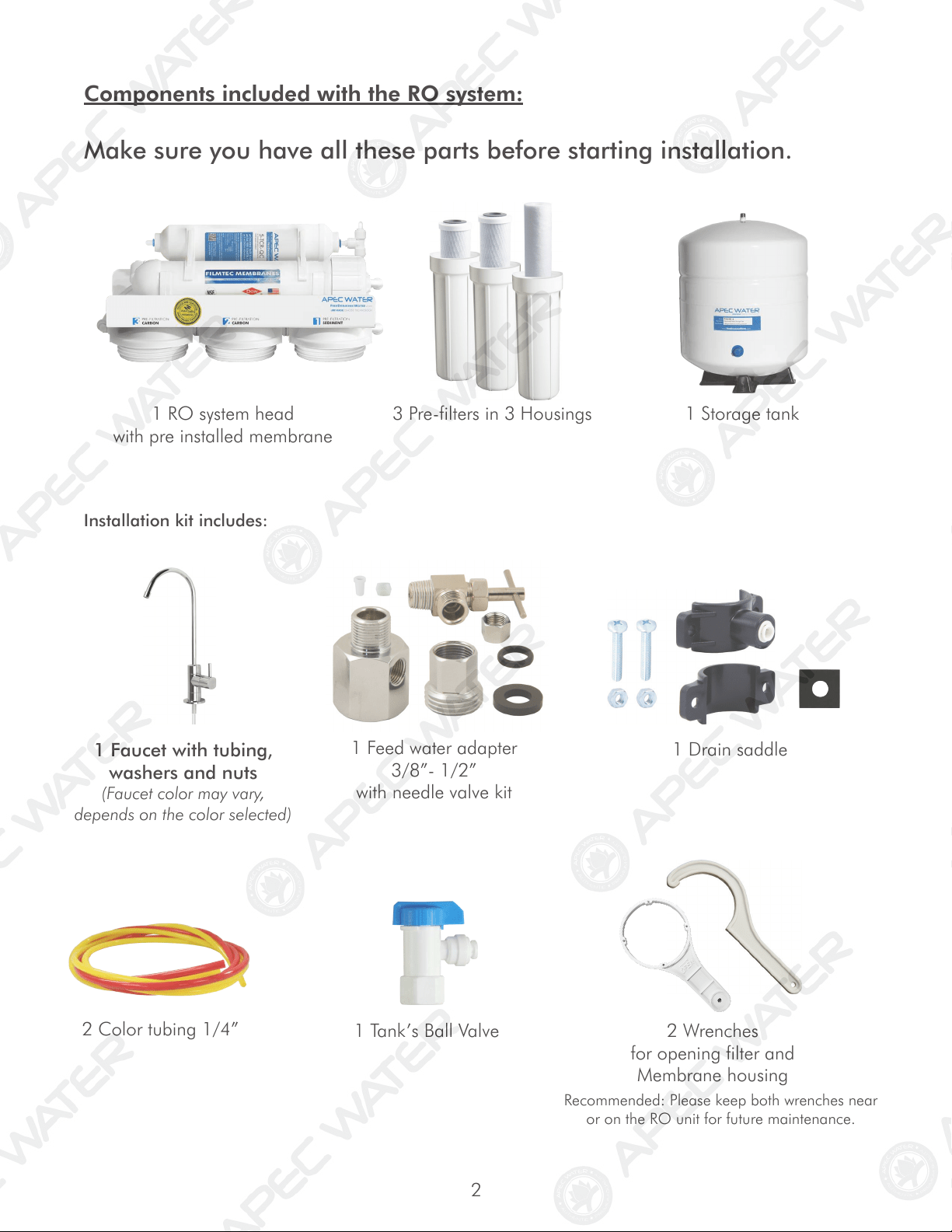
Components included with the RO system:
Make sure you have all these parts before starting installation.
1 RO system head
with pre installed membrane
3 Pre-filters in 3 Housings
1 Storage tank
Installation kit includes:
1 Feed water adapter
3/8”- 1/2”
with needle valve kit
1 Drain saddle
2 Color tubing 1/4”
1 Tank’s Ball Valve 2 Wrenches
for opening filter and
Membrane housing
Recommended: Please keep both wrenches near
or on the RO unit for future maintenance.
3
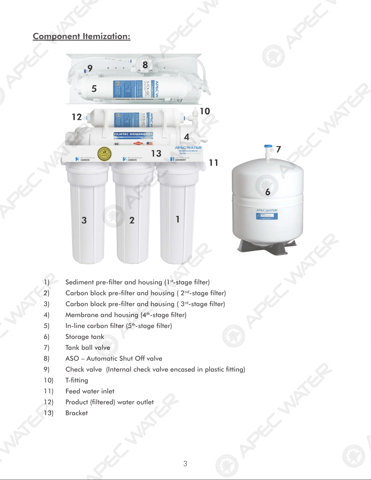
Component Itemization:
1) Sediment pre-filter and housing (1
st
-stage filter)
2) Carbon block pre-filter and housing ( 2
nd
-stage filter)
3) Carbon block pre-filter and housing ( 3
rd
-stage filter)
4) Membrane and housing (4
th
-stage filter)
5) In-line carbon filter (5
th
-stage filter)
6) Storage tank
7) Tank ball valve
8) ASO – Automatic Shut Off valve
9) Check valve (Internal check valve encased in plastic fitting)
10) T-fitting
11) Feed water inlet
12) Product (filtered) water outlet
13) Bracket
4
THERE ARE TWO PARTS TO INSTALLING THE RO SYSTEM:
Part I. Assemble the filters and housings onto the main system
Part II. Installing the system
Note: The RO Membrane Element has already been pre-installed.
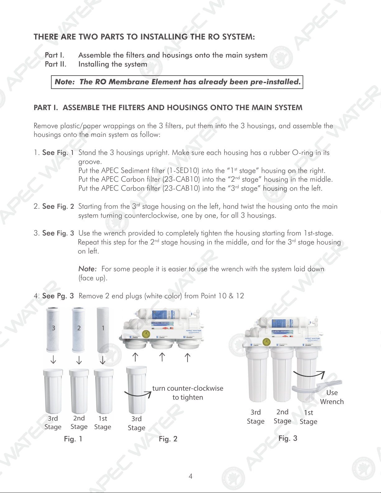
PART I. ASSEMBLE THE FILTERS AND HOUSINGS ONTO THE MAIN SYSTEM
Remove plastic/paper wrappings on the 3 filters, put them into the 3 housings, and assemble the
housings onto the main system as follow:
1. See Fig. 1 Stand the 3 housings upright. Make sure each housing has a rubber O-ring in its
groove.
Put the APEC Sediment filter (1-SED10) into the “1
st
stage” housing on the right.
Put the APEC Carbon filter (23-CAB10) into the “2
nd
stage” housing in the middle.
Put the APEC Carbon filter (23-CAB10) into the “3
rd
stage” housing on the left.
2. See Fig. 2 Starting from the 3
rd
stage housing on the left, hand twist the housing onto the main
system turning counterclockwise, one by one, for all 3 housings.
3. See Fig. 3 Use the wrench provided to completely tighten the housing starting from 1st-stage.
Repeat this step for the 2
nd
stage housing in the middle, and for the 3
rd
stage housing
on left.
Note: For some people it is easier to use the wrench with the system laid down
(face up).
4. See Pg. 3 Remove 2 end plugs (white color) from Point 10 & 12
Fig. 1
Fig. 2
Fig. 3
turn counter-clock
wise
to tighten
3rd
Stage
3rd
Stage
2nd
Stage
1st
Stage
Use
Wr
ench
Use
5
PART II. INSTALLING THE SYSTEM
Space: Make sure there is sufficient space under the counter for installation (an area of about 17”L x
6”W x 18”H for the system, 11”D x 18”H for tank).
The RO system is best installed under the kitchen sink. But if that is not feasible you can install the system
anywhere where there is a cold water supply with sufficient water pressure for the chosen RO model, and
an outlet to drain off the drain water from the system.
Mounting: No need to mount the RO system on the wall. The RO system can stand in the sink cabinet
without mounting, this makes future filter change easy and convenient. If you prefer to mount the system
to the wall, please make sure it can be taken down easily for filter replacement.
Feed Water: RO systems are designed to treat both hard and soft water and can handle incoming TDS
levels up to 2,000 ppm.
Fig. 4
Step 1: Feed Water Connection
The RO system must be connected to the COLD water supply only!
1. Locate the Cold water supply valve under the kitchen sink (the round or oblong handle on
the right side). Turn off the incoming cold water completely by turning the shut off handle
clockwise.
Note: If the cold water shut off valve can not turn off the water, the main water supply
to the house must be shut off for the installation. Another option is to use a “self
piercing saddle valve” from APEC or from a local hardware store.
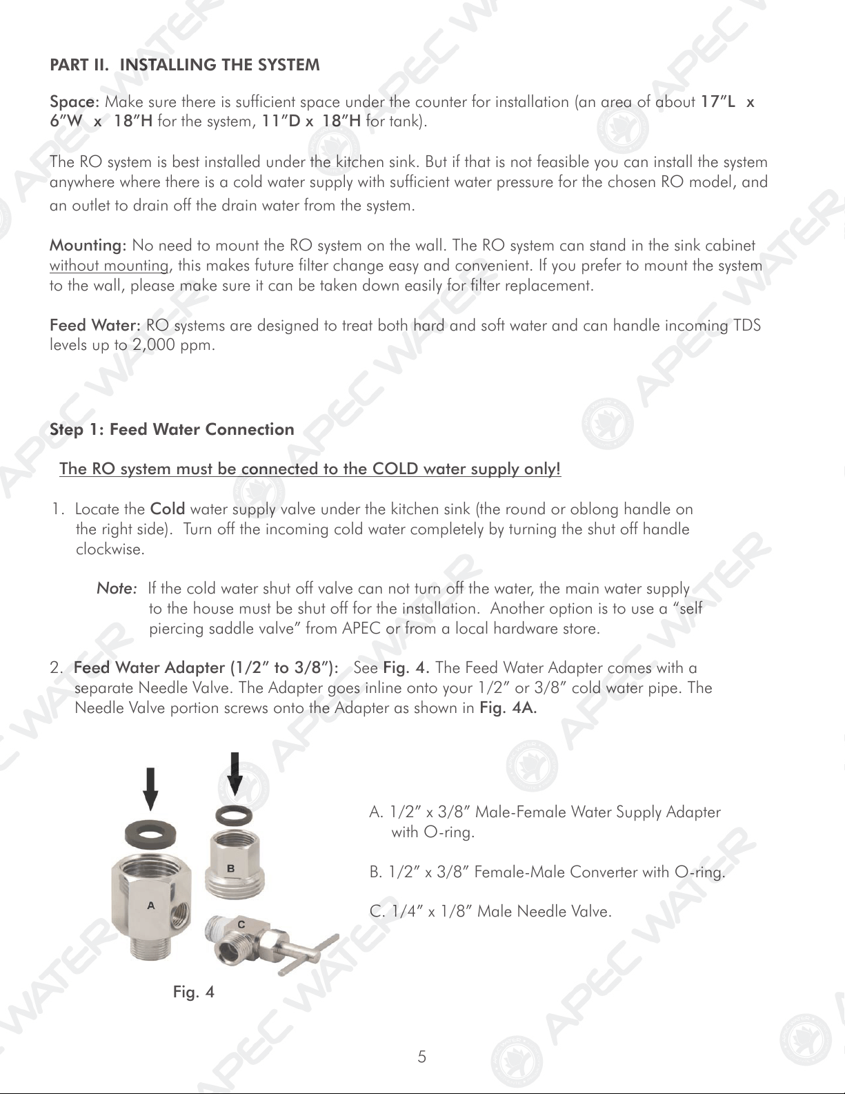
2. Feed Water Adapter (1/2” to 3/8”): See Fig. 4. The Feed Water Adapter comes with a
separate Needle Valve. The Adapter goes inline onto your 1/2” or 3/8” cold water pipe. The
Needle Valve portion screws onto the Adapter as shown in Fig. 4A.
A. 1/2” x 3/8” Male-Female Water Supply Adapter
with O-ring.
B. 1/2” x 3/8” Female-Male Converter with O-ring.
C. 1/4” x 1/8” Male Needle Valve.
6
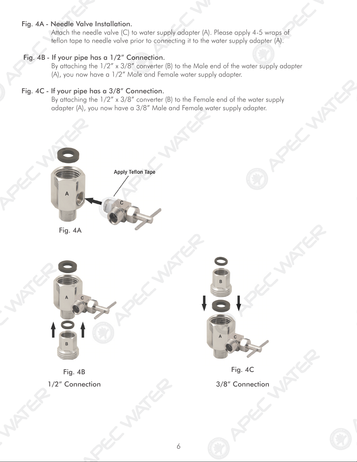
Fig. 4A - Needle Valve Installation.
Attach the needle valve (C) to water supply adapter (A). Please apply 4-5 wraps of
teflon tape to needle valve prior to connecting it to the water supply adapter (A).
Fig. 4B - If your pipe has a 1/2” Connection.
By attaching the 1/2” x 3/8” converter (B) to the Male end of the water supply adapter
(A), you now have a 1/2” Male and Female water supply adapter.
Fig. 4C - If your pipe has a 3/8” Connection.
By attaching the 1/2” x 3/8” converter (B) to the Female end of the water supply
adapter (A), you now have a 3/8” Male and Female water supply adapter.
Fig. 4A
Fig. 4B
1/2” Connection 3/8” Connection
Fig. 4C
7
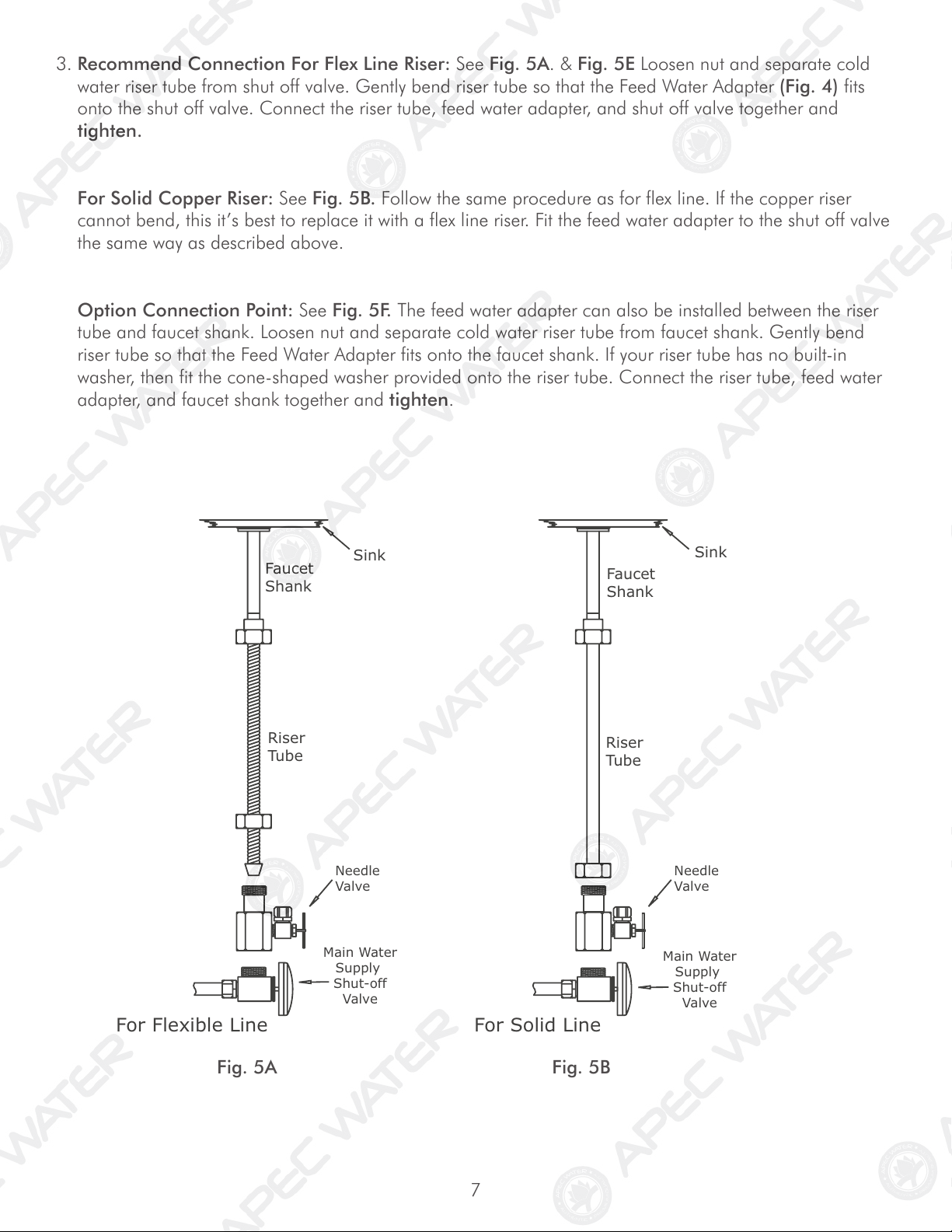
3. Recommend Connection For Flex Line Riser: See Fig. 5A. & Fig. 5E Loosen nut and separate cold
water riser tube from shut off valve. Gently bend riser tube so that the Feed Water Adapter (Fig. 4) fits
onto the shut off valve. Connect the riser tube, feed water adapter, and shut off valve together and
tighten.
For Solid Copper Riser: See Fig. 5B. Follow the same procedure as for flex line. If the copper riser
cannot bend, this it’s best to replace it with a flex line riser. Fit the feed water adapter to the shut off valve
the same way as described above.
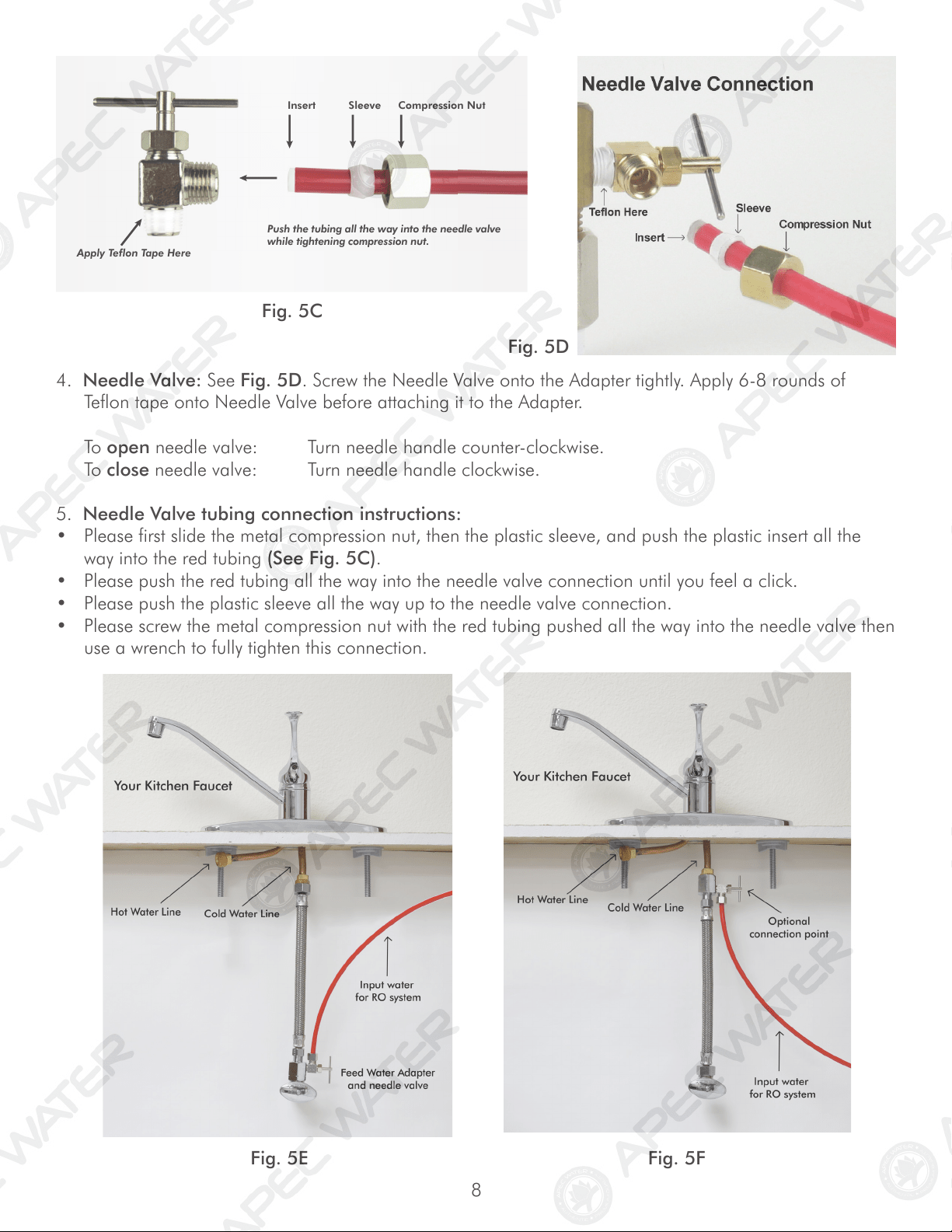
Option Connection Point: See Fig. 5F. The feed water adapter can also be installed between the riser
tube and faucet shank. Loosen nut and separate cold water riser tube from faucet shank. Gently bend
riser tube so that the Feed Water Adapter fits onto the faucet shank. If your riser tube has no built-in
washer, then fit the cone-shaped washer provided onto the riser tube. Connect the riser tube, feed water
adapter, and faucet shank together and tighten.
Riser
Tube
For Flexible Line
Faucet
Shank
Main Water
Supply
Shut-off
Valve
Riser
Tube
For Solid Line
Faucet
Shank
Needle
Valve
Needle
Valve
Main Wate
r
Supply
Shut-off
Valve
Sink
Sink
Fig. 5A Fig. 5B
8
Fig. 5C
5. Needle Valve tubing connection instructions:
• Please first slide the metal compression nut, then the plastic sleeve, and push the plastic insert all the
way into the red tubing (See Fig. 5C).
• Please push the red tubing all the way into the needle valve connection until you feel a click.
• Please push the plastic sleeve all the way up to the needle valve connection.
• Please screw the metal compression nut with the red tubing pushed all the way into the needle valve then
use a wrench to fully tighten this connection.
Fig. 5E Fig. 5F
4. Needle Valve: See Fig. 5D. Screw the Needle Valve onto the Adapter tightly. Apply 6-8 rounds of
Teflon tape onto Needle Valve before attaching it to the Adapter.
To open needle valve: Turn needle handle counter-clockwise.
To close needle valve: Turn needle handle clockwise.
Fig. 5D
Insert Sleeve Compression Nut
Apply Teflon Tape Here
Push the tubing all the way into the needle valve
while tightening compression nut.
9
MOUNT DRAIN
SADDLE AT
EITHER
LOCATION
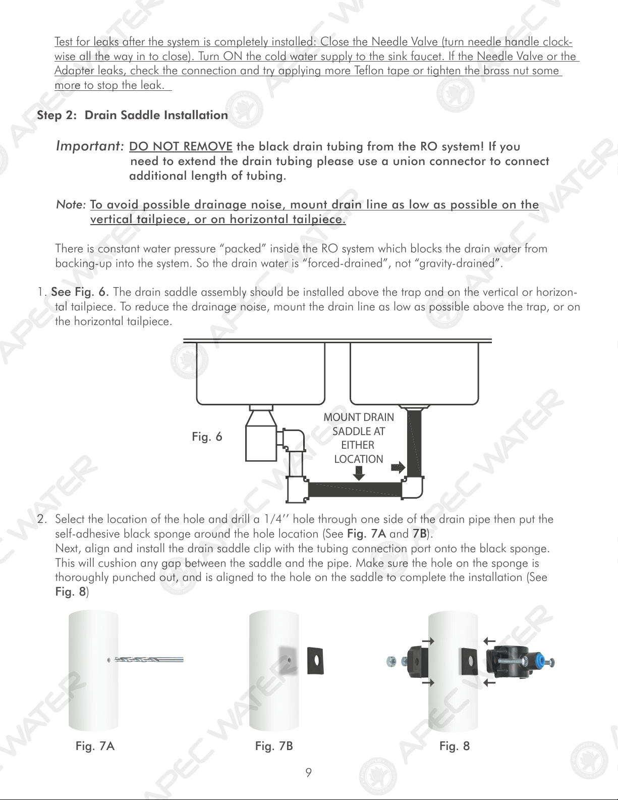
Step 2: Drain Saddle Installation
Important: DO NOT REMOVE the black drain tubing from the RO system! If you
need to extend the drain tubing please use a union connector to connect
additional length of tubing.
Note: To avoid possible drainage noise, mount drain line as low as possible on the
vertical tailpiece, or on horizontal tailpiece.
There is constant water pressure “packed” inside the RO system which blocks the drain water from
backing-up into the system. So the drain water is “forced-drained”, not “gravity-drained”.
1. See Fig. 6. The drain saddle assembly should be installed above the trap and on the vertical or horizon-
tal tailpiece. To reduce the drainage noise, mount the drain line as low as possible above the trap, or on
the horizontal tailpiece.
2. Select the location of the hole and drill a 1/4’’ hole through one side of the drain pipe then put the
self-adhesive black sponge around the hole location (See Fig. 7A and 7B).
Next, align and install the drain saddle clip with the tubing connection port onto the black sponge.
This will cushion any gap between the saddle and the pipe. Make sure the hole on the sponge is
thoroughly punched out, and is aligned to the hole on the saddle to complete the installation (See
Fig. 8)
Fig. 6
Fig. 7A Fig. 8
Test for leaks after the system is completely installed: Close the Needle Valve (turn needle handle clock-
wise all the way in to close). Turn ON the cold water supply to the sink faucet. If the Needle Valve or the
Adapter leaks, check the connection and try applying more Teflon tape or tighten the brass nut some
more to stop the leak.
Fig. 7B
10
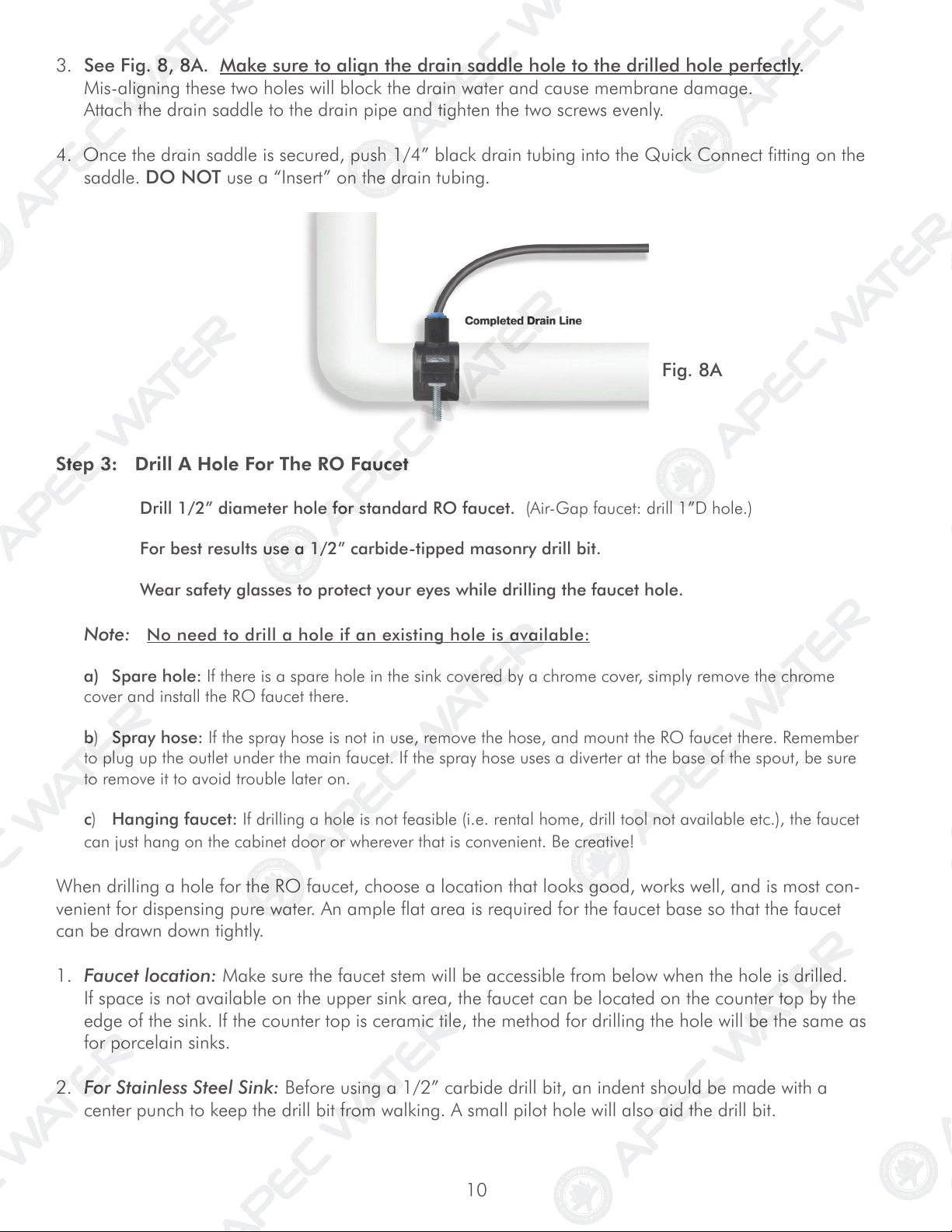
3. See Fig. 8, 8A. Make sure to align the drain saddle hole to the drilled hole perfectly.
Mis-aligning these two holes will block the drain water and cause membrane damage.
Attach the drain saddle to the drain pipe and tighten the two screws evenly.
4. Once the drain saddle is secured, push 1/4” black drain tubing into the Quick Connect fitting on the
saddle. DO NOT use a “Insert” on the drain tubing.
Fig. 8A
Step 3: Drill A Hole For The RO Faucet
Drill 1/2” diameter hole for standard RO faucet. (Air-Gap faucet: drill 1”D hole.)
For best results use a 1/2” carbide-tipped masonry drill bit.
Wear safety glasses to protect your eyes while drilling the faucet hole.
Note: No need to drill a hole if an existing hole is available:
a) Spare hole: If there is a spare hole in the sink covered by a chrome cover, simply remove the chrome
cover and install the RO faucet there.
b) Spray hose: If the spray hose is not in use, remove the hose, and mount the RO faucet there. Remember
to plug up the outlet under the main faucet. If the spray hose uses a diverter at the base of the spout, be sure
to remove it to avoid trouble later on.
c) Hanging faucet: If drilling a hole is not feasible (i.e. rental home, drill tool not available etc.), the faucet
can just hang on the cabinet door or wherever that is convenient. Be creative!
When drilling a hole for the RO faucet, choose a location that looks good, works well, and is most con-
venient for dispensing pure water. An ample flat area is required for the faucet base so that the faucet
can be drawn down tightly.
1. Faucet location: Make sure the faucet stem will be accessible from below when the hole is drilled.
If space is not available on the upper sink area, the faucet can be located on the counter top by the
edge of the sink. If the counter top is ceramic tile, the method for drilling the hole will be the same as
for porcelain sinks.
2. For Stainless Steel Sink: Before using a 1/2” carbide drill bit, an indent should be made with a
center punch to keep the drill bit from walking. A small pilot hole will also aid the drill bit.
11
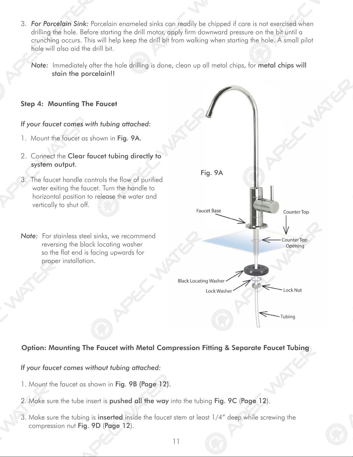
Black Locating Washer
Lock Washer
Lock Nut
Tubing
Counter Top
Counter Top
Opening
Faucet Base
3. For Porcelain Sink: Porcelain enameled sinks can readily be chipped if care is not exercised when
drilling the hole. Before starting the drill motor, apply firm downward pressure on the bit until a
crunching occurs. This will help keep the drill bit from walking when starting the hole. A small pilot
hole will also aid the drill bit.
Note: Immediately after the hole drilling is done, clean up all metal chips, for metal chips will
stain the porcelain!!
Note: For stainless steel sinks, we recommend
reversing the black locating washer
so the flat end is facing upwards for
proper installation.
Fig. 9A
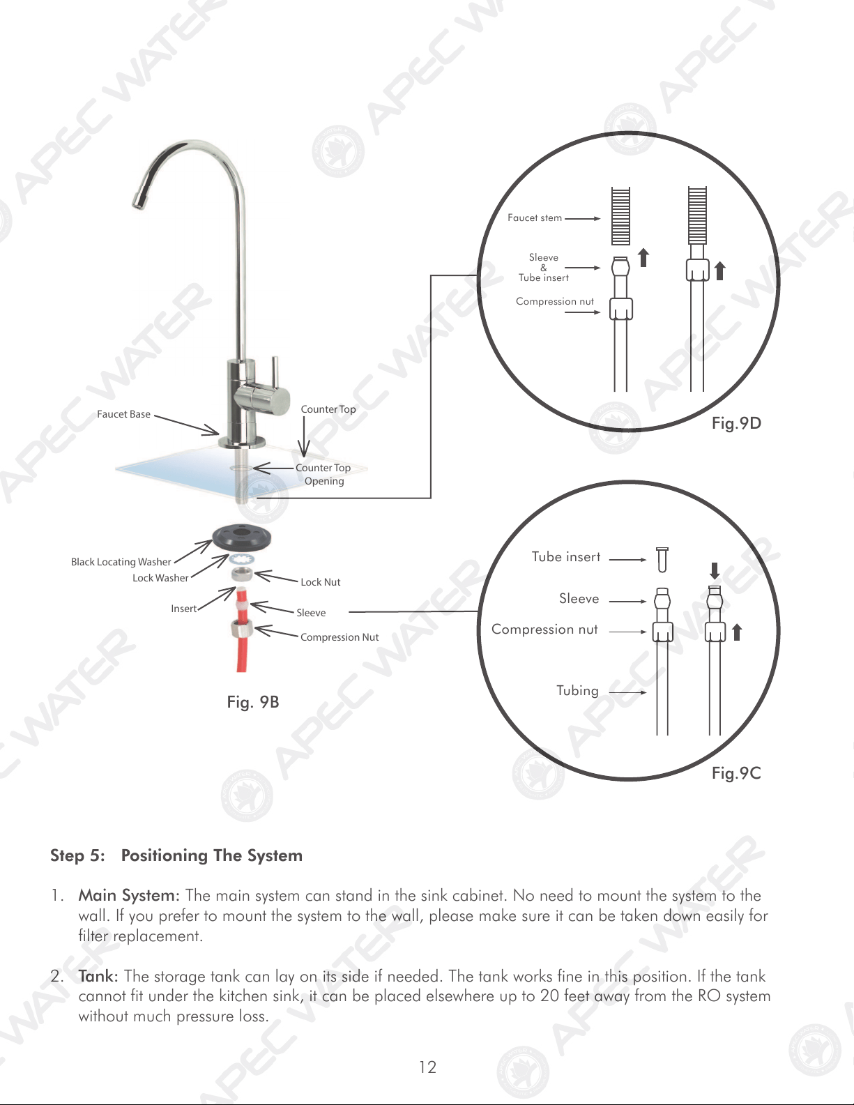
If your faucet comes without tubing attached:
Option: Mounting The Faucet with Metal Compression Fitting & Separate Faucet Tubing
1. Mount the faucet as shown in Fig. 9B (Page 12).
2. Make sure the tube insert is pushed all the way into the tubing Fig. 9C (Page 12).
3. Make sure the tubing is inserted inside the faucet stem at least 1/4” deep while screwing the
compression nut Fig. 9D (Page 12).
Step 4: Mounting The Faucet
If your faucet comes with tubing attached:
1. Mount the faucet as shown in Fig. 9A.
2. Connect the Clear faucet tubing directly to
system output.
3. The faucet handle controls the flow of purified
water exiting the faucet. Turn the handle to
horizontal position to release the water and
vertically to shut off.
12
Step 5: Positioning The System
1. Main System: The main system can stand in the sink cabinet. No need to mount the system to the
wall. If you prefer to mount the system to the wall, please make sure it can be taken down easily for
filter replacement.
2. Tank: The storage tank can lay on its side if needed. The tank works fine in this position. If the tank
cannot fit under the kitchen sink, it can be placed elsewhere up to 20 feet away from the RO system
without much pressure loss.
Faucet Base
Black Locating Washer
Lock Washer
Lock Nut
Insert
Sleeve
C
ompression Nut
Counter Top
Counter Top
Opening
Tube insert
Sleeve
Compression nut
Tubing
Faucet stem
Sleeve
&
Tube insert
Compression nut
Fig. 9B
Fig.9D
Fig.9C
13
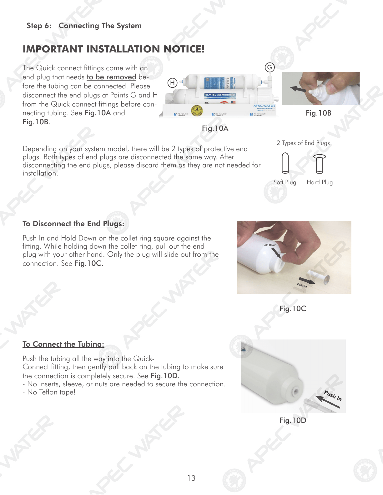
IMPORTANT INSTALLATION NOTICE!
The Quick connect fittings come with an
end plug that needs to be removed be-
fore the tubing can be connected. Please
disconnect the end plugs at Points G and H
from the Quick connect fittings before con-
necting tubing. See Fig.10A and
Fig.10B.
Fig.10A
Fig.10B
Step 6: Connecting The System
Fig.10C
Fig.10D
To Disconnect the End Plugs:
Push In and Hold Down on the collet ring square against the
fitting. While holding down the collet ring, pull out the end
plug with your other hand. Only the plug will slide out from the
connection. See Fig.10C.
Depending on your system model, there will be 2 types of protective end
plugs. Both types of end plugs are disconnected the same way. After
disconnecting the end plugs, please discard them as they are not needed for
installation.
Soft Plug Hard Plug
2 Types of End Plugs
To Connect the Tubing:
Push the tubing all the way into the Quick-
Connect fitting, then gently pull back on the tubing to make sure
the connection is completely secure. See Fig.10D.
- No inserts, sleeve, or nuts are needed to secure the connection.
- No Teflon tape!
H
G
14
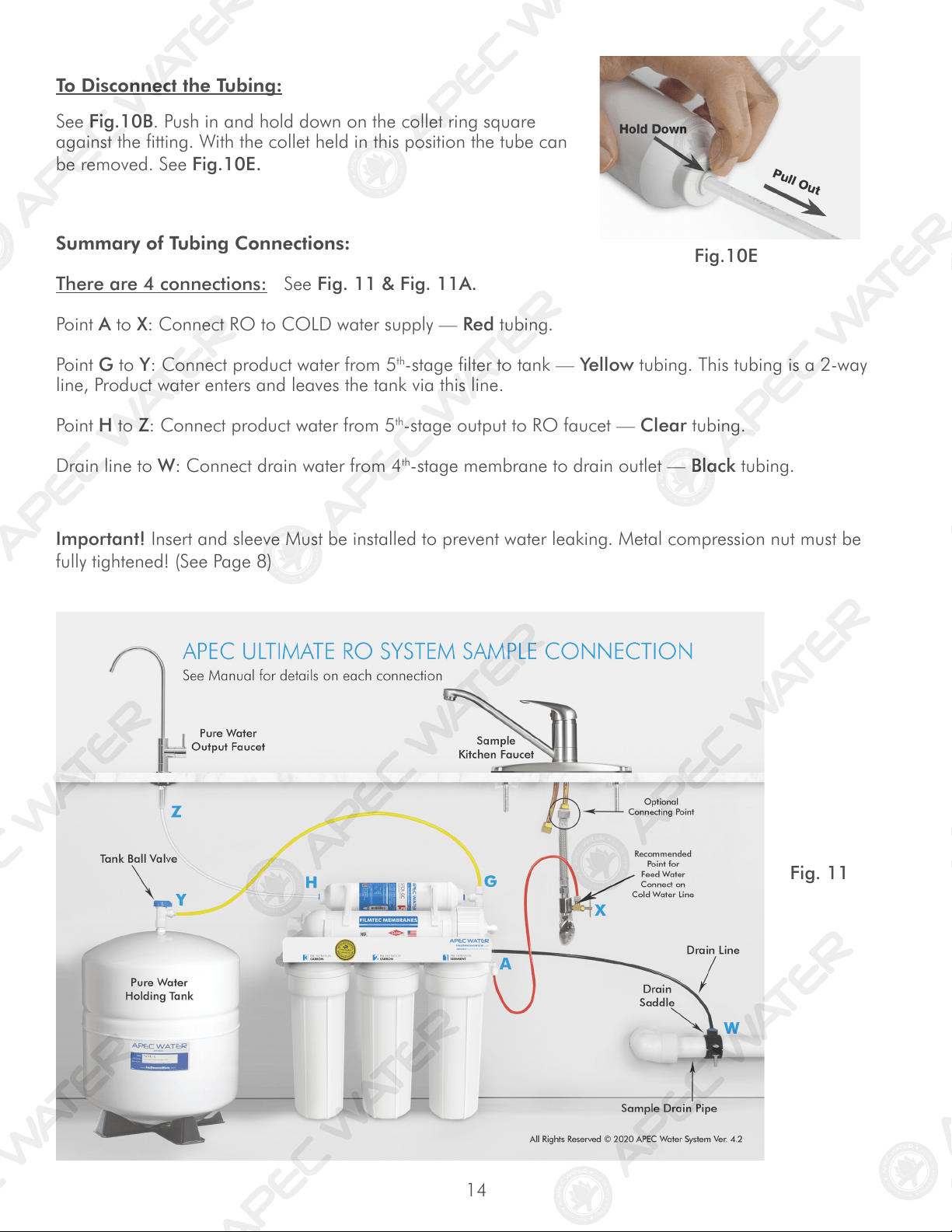
Summary of Tubing Connections:
There are 4 connections: See Fig. 11 & Fig. 11A.
Point A to X: Connect RO to COLD water supply — Red tubing.
Point G to Y: Connect product water from 5
th
-stage filter to tank — Yellow tubing. This tubing is a 2-way
line, Product water enters and leaves the tank via this line.
Point H to Z: Connect product water from 5
th
-stage output to RO faucet — Clear tubing.
Drain line to W: Connect drain water from 4
th
-stage membrane to drain outlet — Black tubing.
Fig. 11
Fig.10E
To Disconnect the Tubing:
See Fig.10B. Push in and hold down on the collet ring square
against the fitting. With the collet held in this position the tube can
be removed. See Fig.10E.
Important! Insert and sleeve Must be installed to prevent water leaking. Metal compression nut must be
fully tightened! (See Page 8)
15
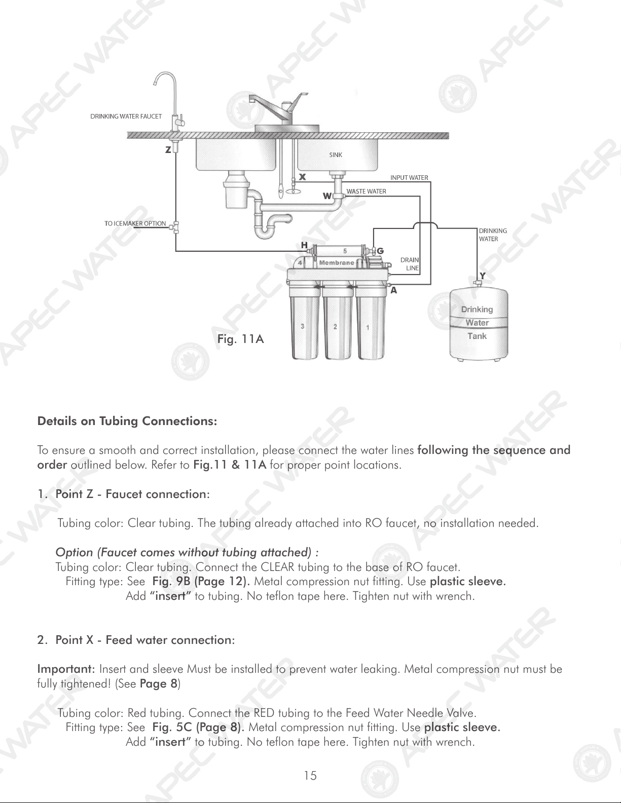
Fig. 11A
Details on Tubing Connections:
To ensure a smooth and correct installation, please connect the water lines following the sequence and
order outlined below. Refer to Fig.11 & 11A for proper point locations.
1. Point Z - Faucet connection:
Tubing color: Clear tubing. The tubing already attached into RO faucet, no installation needed.
Option (Faucet comes without tubing attached) :
Tubing color: Clear tubing. Connect the CLEAR tubing to the base of RO faucet.
Fitting type: See Fig. 9B (Page 12). Metal compression nut fitting. Use plastic sleeve.
Add “insert” to tubing. No teflon tape here. Tighten nut with wrench.
2. Point X - Feed water connection:
Important: Insert and sleeve Must be installed to prevent water leaking. Metal compression nut must be
fully tightened! (See Page 8)
Tubing color: Red tubing. Connect the RED tubing to the Feed Water Needle Valve.
Fitting type: See Fig. 5C (Page 8). Metal compression nut fitting. Use plastic sleeve.
Add “insert” to tubing. No teflon tape here. Tighten nut with wrench.
16
3. Point W - Drain water connection:
Tubing color: Black tubing. Connect the BLACK tubing from the RO to the Drain Saddle.
Fitting type: Simply push the Clear tubing into the Quick Connect fitting. No Inserts, Sleeves or Nuts
are needed to secure the connection. No Teflon tape needed here.
4. Point A - System water inlet (to Stage 1 pre-filter) connection:
Tubing color: Red tubing. Connect the RED tubing from the Feed Water Valve to the RO’s stage -1
prefilter.
Fitting type: Quick Connect fitting See Fig. 10D (Page 13). Simply push the Red tubing into the QC
fitting. No Inserts, Sleeves or Nuts are needed to secure the connection. No Teflon tape
needed here.
5. Point H - Stage-5 filtered water to faucet connection:
Tubing color: Clear tubing. Connect the CLEAR tubing from the faucet base stud to the Stage-5 filter’s
outflow end at point H. (See “Flow -->” arrow on the filter is the output to faucet at Point Z.)
Fitting type: Quick Connect: Simply push the Clear tubing into the QC fitting. No Inserts, Sleeves or
Nuts are needed to secure the connection. No Teflon tape needed here.
6. Point G - Stage-5 filter’s T-fitting connection:
Tubing color: Yellow tubing. Connect the YELLOW tubing to Stage-5 filter’s T-fitting.
Fitting type: Quick Connect: Simply push the Yellow tubing into the QC fitting. No Inserts, Sleeves or
Nuts are needed to secure the connection. No Teflon tape needed here.
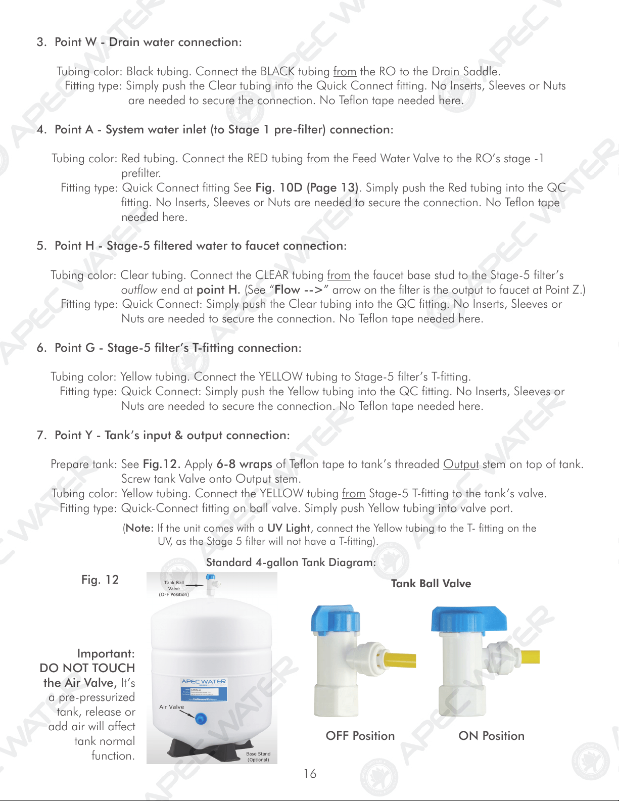
7. Point Y - Tank’s input & output connection:
Prepare tank: See Fig.12. Apply 6-8 wraps of Teflon tape to tank’s threaded Output stem on top of tank.
Screw tank Valve onto Output stem.
Tubing color: Yellow tubing. Connect the YELLOW tubing from Stage-5 T-fitting to the tank’s valve.
Fitting type: Quick-Connect fitting on ball valve. Simply push Yellow tubing into valve port.
Standard 4-gallon Tank Diagram:
Tank Ball Valve
OFF Position ON Position
Fig. 12
Important:
DO NOT TOUCH
the Air Valve, It’s
a pre-pressurized
tank, release or
add air will affect
tank normal
function.
(Note: If the unit comes with a UV Light, connect the Yellow tubing to the T- fitting on the
UV, as the Stage 5 filter will not have a T-fitting).
17
Shut Off Valve
Tee fitting for icemaker & output
Ball Valve Position
ON OFF
Z
H
Y
X
Insert
Sleeve
Tube
Metal Nut
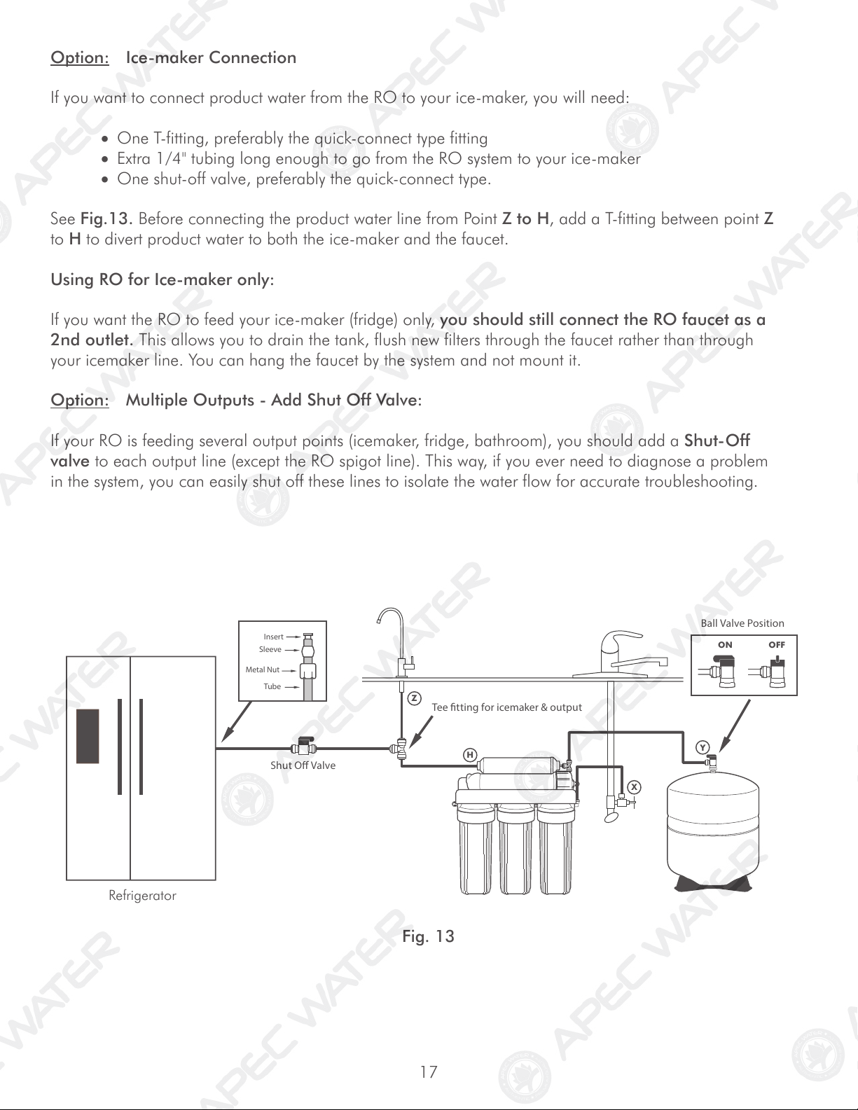
Option: Ice-maker Connection
If you want to connect product water from the RO to your ice-maker, you will need:
• One T-fitting, preferably the quick-connect type fitting
• Extra 1/4" tubing long enough to go from the RO system to your ice-maker
• One shut-off valve, preferably the quick-connect type.
See Fig.13. Before connecting the product water line from Point Z to H, add a T-fitting between point Z
to H to divert product water to both the ice-maker and the faucet.
Using RO for Ice-maker only:
If you want the RO to feed your ice-maker (fridge) only, you should still connect the RO faucet as a
2nd outlet. This allows you to drain the tank, flush new filters through the faucet rather than through
your icemaker line. You can hang the faucet by the system and not mount it.
Option: Multiple Outputs - Add Shut Off Valve:
If your RO is feeding several output points (icemaker, fridge, bathroom), you should add a Shut-Off
valve to each output line (except the RO spigot line). This way, if you ever need to diagnose a problem
in the system, you can easily shut off these lines to isolate the water flow for accurate troubleshooting.
Fig. 13
Refrigerator
18
3. Wait for tank to fill: Before usage, allow the tank to fill. Tank normally takes 2-3 hours to fill.
When the tank is filled, the RO will shut off automatically.
4. Drain Tank: Please do not use the first tank of water. Once the tank has filled, open
the drinking water faucet to drain the tank and filters. It will usually take
about 5 minutes to flush the unit. When the tank is completely empty water will
simply trickle out the faucet. At this time, please close the drinking faucet and allow
the unit another 2-3 hours to refill the tank. The 2nd tank of water will be ready for
use.
Please Note: Water may come out dark for the first few seconds on the initial
flush, and then clear right up. This is due to the GAC (granular activated carbon)
post filter.
5. Clean up area: Allow the system to run while cleaning up tools and work area.
6. Check for leaks! Make sure no leaking at joints, fittings, valves, and tubing connections.
Congratulations! You have successfully installed the Reverse Osmosis System!
* * * End Installation Section * * *
Step 7: System Start-Up
1. Turn on feed water: Slowly, turn on your Cold water supply. Open the Needle Valve (turn counter-
clockwise) to allow the raw water to enter the system. Check for leaks!
2. Open tank valve: Open the tank’s ball valve to allow water to enter the tank. The tank’s valve is
“On” when the valve handle is parallel (in the same direction) with the valve’s outlet (see Fig. 12).
Check for leaks!
Tips!
If Point X leaks after you have tightened the brass nut, check to make sure you did put
the plastic “insert” into the tubing. If the insert is already in place, then try applying Teflon
tape from the threaded metal stud all the way to the plastic tubing, wrap the whole connec-
tion with 8-10 rounds of Teflon tape. Smooth out the tape on the threaded part with your
fingers. Tighten brass nut again. This should stop the leak.
If the plastic sleeve is damaged, you can use the metal sleeve, but you need to apply
Teflon tape as described above, this should stop the leak.
If Point Y (tank ball valve) leaks, please make sure there was 6-8 wraps of Teflon tape
applied onto the tank metal stem before screwing on tank ball valve.
19
SYSTEM MAINTENANCE
The system requires very little maintenance. Just change the filter cartridges regularly as suggested below.
Keep the system indoors away from extreme heat or cold temperatures, and run the system within its
reasonable output capacity (i.e. allow the system to rest at least a few hours a day).
To properly maintain your APEC drinking water system,
please use only genuine APEC Water replacement filters at
www.freedrinkingwater.com/filters
Stages 1, 2, 3 Pre-Filters: Replace every 12 months.
(FILTER-SET) (Private well water source: may need to replace pre-filters sooner than
12 months due to heavy sediments and other particles.)
Stage-4 Membrane: City Water: Replace every 3-5 years depending on input
(MEM-90) use MEM-45 for pump models water quality, water usage, and prefilter change maintenance
Private Well Water: Replace every 2-3 years depending on
well water quality, and prefilter change maintenance.
Stage-5 Carbon Filter: Replace every 3-5 years: It’s best to replace this filter when
(5-TCR-QC) replacing the stage-4 membrane.
Filter Housing O-rings: We recommend replacing the filter housing O-ring every year or
when replacing the 3 pre-filters.
Important! It is important to change the 3 pre-filters timely, at least every 6-12 months. The
pre-filters protect the stage-4 membrane. If they are not changed timely and
become over-depleted, the membrane life capacity may be reduced and affect
contaminant removal and pure water production rate.
It’s best to use APEC replacement filters. Using “non APEC”and lesser quality filters
may clog up the RO system and damage the membrane.
We recommend that stage 1-3 filter housings be replaced every 5 years.
FILTER CHANGE INSTRUCTIONS
How To Replace Stages 1, 2, 3 Pre-Filters:
1) Turn OFF cold water supply to RO system. Turn OFF tank ball-valve. Turn on the RO faucet lever to
relieve the built-up pressure inside the RO system. This will make opening the housings easier.
2) Open housing: Have the RO standing upright. Slip the plastic wrench onto the 1st housing. Looking
down from a top view, you should open the housing turning clockwise. If necessary, lay RO down on
the floor to get a better leverage. If the housing is too tight, use a hammer and gently tap on the wrench
handle to help turn the wrench. See Fig.14 (Page 20).
20
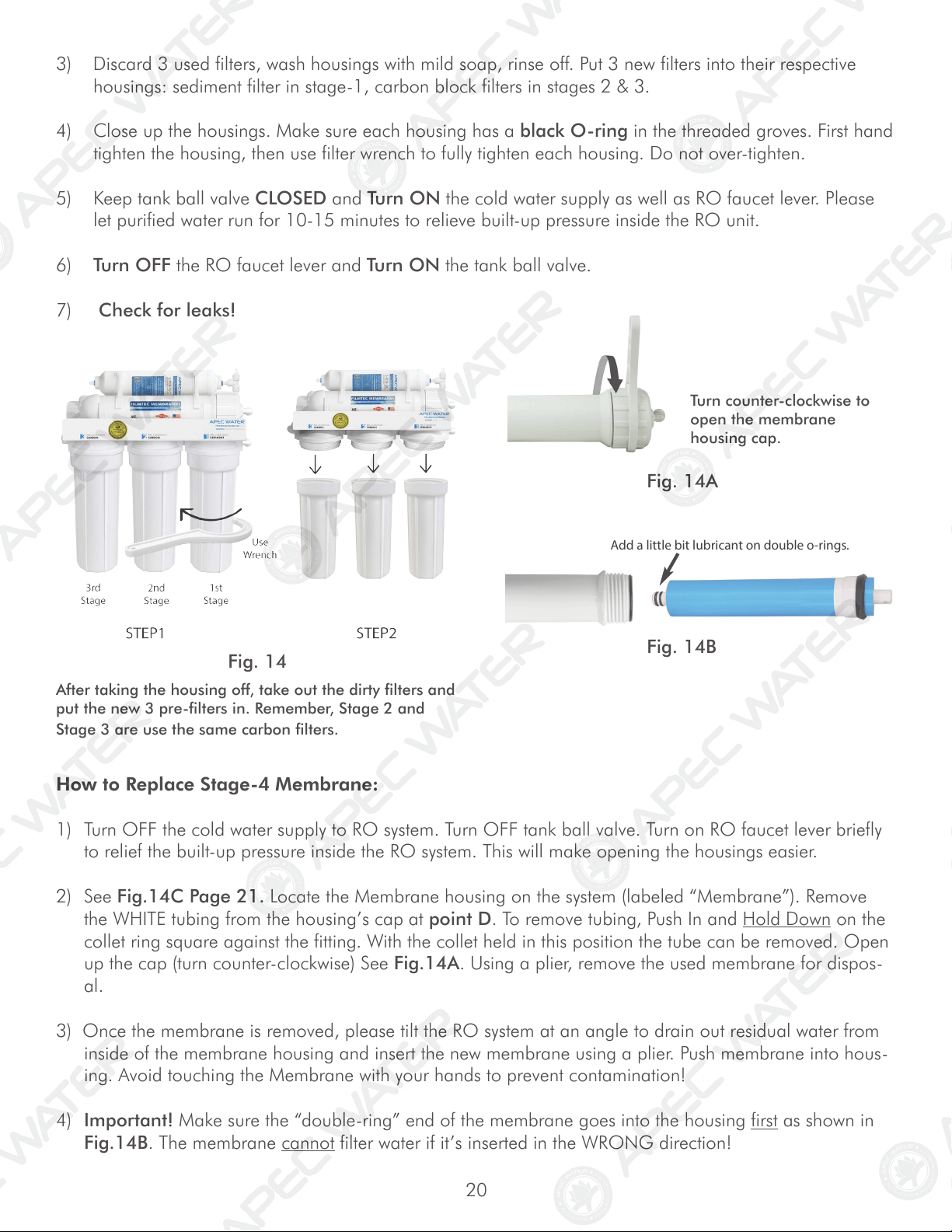
3) Discard 3 used filters, wash housings with mild soap, rinse off. Put 3 new filters into their respective
housings: sediment filter in stage-1, carbon block filters in stages 2 & 3.
4) Close up the housings. Make sure each housing has a black O-ring in the threaded groves. First hand
tighten the housing, then use filter wrench to fully tighten each housing. Do not over-tighten.
5) Keep tank ball valve CLOSED and Turn ON the cold water supply as well as RO faucet lever. Please
let purified water run for 10-15 minutes to relieve built-up pressure inside the RO unit.
6) Turn OFF the RO faucet lever and Turn ON the tank ball valve.
7) Check for leaks!
How to Replace Stage-4 Membrane:
1) Turn OFF the cold water supply to RO system. Turn OFF tank ball valve. Turn on RO faucet lever briefly
to relief the built-up pressure inside the RO system. This will make opening the housings easier.
2) See Fig.14C Page 21. Locate the Membrane housing on the system (labeled “Membrane”). Remove
the WHITE tubing from the housing’s cap at point D. To remove tubing, Push In and Hold Down on the
collet ring square against the fitting. With the collet held in this position the tube can be removed. Open
up the cap (turn counter-clockwise) See Fig.14A. Using a plier, remove the used membrane for dispos-
al.
3) Once the membrane is removed, please tilt the RO system at an angle to drain out residual water from
inside of the membrane housing and insert the new membrane using a plier. Push membrane into hous-
ing. Avoid touching the Membrane with your hands to prevent contamination!
4) Important! Make sure the “double-ring” end of the membrane goes into the housing first as shown in
Fig.14B. The membrane cannot filter water if it’s inserted in the WRONG direction!
After taking the housing off, take out the dirty filters and
put the new 3 pre-filters in. Remember, Stage 2 and
Stage 3 are use the same carbon filters.
Fig. 14
Add a little bit lubricant on double o-rings.
Turn counter-clockwise to
open the membrane
housing cap.
Fig. 14A
Fig. 14B
21
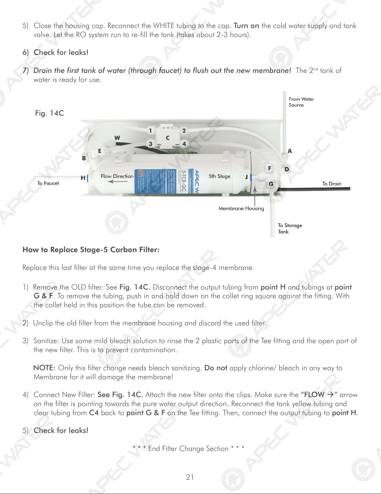
How to Replace Stage-5 Carbon Filter:
Replace this last filter at the same time you replace the stage-4 membrane.
1) Remove the OLD filter: See Fig. 14C. Disconnect the output tubing from point H and tubings at point
G & F. To remove the tubing, push in and hold down on the collet ring square against the fitting. With
the collet held in this position the tube can be removed.
2) Unclip the old filter from the membrane housing and discard the used filter.
3) Sanitize: Use some mild bleach solution to rinse the 2 plastic ports of the Tee fitting and the open port of
the new filter. This is to prevent contamination.
NOTE: Only this filter change needs bleach sanitizing. Do not apply chlorine/ bleach in any way to
Membrane for it will damage the membrane!
4) Connect New Filter: See Fig. 14C. Attach the new filter onto the clips. Make sure the “FLOW ” arrow
on the filter is pointing towards the pure water output direction. Reconnect the tank yellow tubing and
clear tubing from C4 back to point G & F on the Tee fitting. Then, connect the output tubing to point H.
5) Check for leaks!
* * * End Filter Change Section * * *
Fig. 14C
5) Close the housing cap. Reconnect the WHITE tubing to the cap. Turn on the cold water supply and tank
valve. Let the RO system run to re-fill the tank (takes about 2-3 hours).
6) Check for leaks!
7) Drain the first tank of water (through faucet) to flush out the new membrane! The 2
nd
tank of
water is ready for use.
22
23
OWNER’S MANUAL
Please read this section for useful RO system and mainte-
nance information.
TABLE OF CONTENT
Part I: RO Basics
Basic terms ................................................................................. page 24
System flow diagram ................................................................... page 24
Water pressure -- The most important factor ............................... page 25
Tank -- Fill up time. Fill up volume. Delivery pressure ................ page 25-26
Icemaker and multiple output points ........................................... page 26
Insufficient water Pressure -- Problems with non-pump systems .... page 27
How to test your water pressure ................................................. page 27
Premature membrane failure ...................................................... page 27
Part II: Trouble-shoot Guide
RO Head diagram ....................................................................... page 28
Air bubbles ................................................................................. page 29
No water at dispensing faucet ...................................................... page 29
Slow output ................................................................................. page 30
Filter housing is leaking ............................................................... page 30
TDS (Total Dissolved Solids) Level Reads Higher Than Normal ....... page 31
There is a leak at the tank ball valve connection .......................... page 32
System shut off is abnormal ......................................................... page 32
How to Test RO’s Shut-Off Function .............................................. page 33
Pure water still tastes like tap water ............................................. page 33
RO Makes Humming Noise ......................................................... page 34
24
Fig. 15
This section provides basic concepts on how an RO system works, how it performs in relation to your
house’s water condition. We hope this information helps keep your ROES system running at top
performance for years to come.
1) Basic Terms
GPD = Gallons Per Day (flow rate)
PSI = Pounds per Square Inch (pressure)
TDS = Total Dissolved Solids (contaminants)
PPM = Parts Per Million (unit used to measure TDS level)
TDS Meter = A digital meter for measuring the TDS level in the water
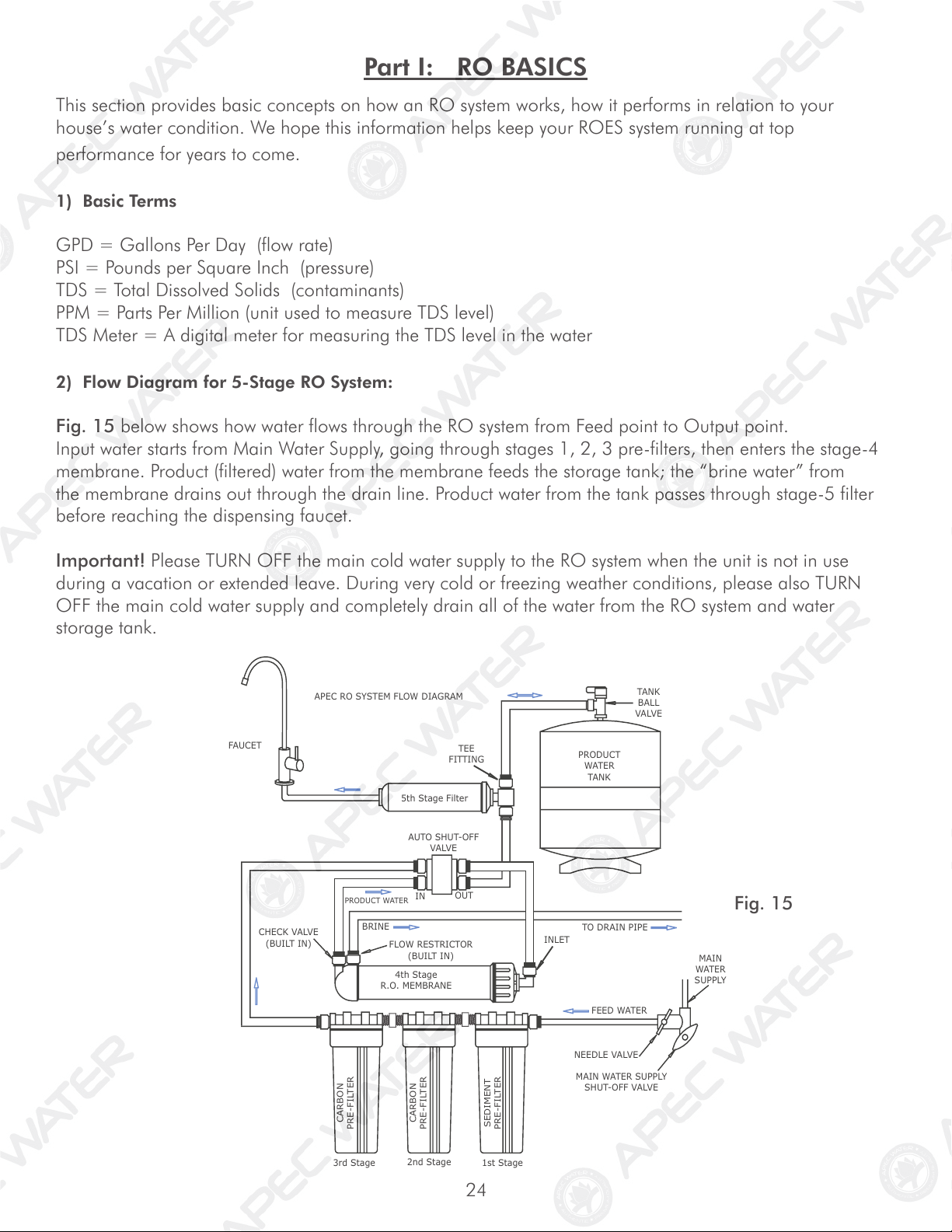
2) Flow Diagram for 5-Stage RO System:
Fig. 15 below shows how water flows through the RO system from Feed point to Output point.
Input water starts from Main Water Supply, going through stages 1, 2, 3 pre-filters, then enters the stage-4
membrane. Product (filtered) water from the membrane feeds the storage tank; the “brine water” from
the membrane drains out through the drain line. Product water from the tank passes through stage-5 filter
before reaching the dispensing faucet.
Important! Please TURN OFF the main cold water supply to the RO system when the unit is not in use
during a vacation or extended leave. During very cold or freezing weather conditions, please also TURN
OFF the main cold water supply and completely drain all of the water from the RO system and water
storage tank.
Part I: RO BASICS
APEC RO SYSTEM FLOW DIAGRAM
5th Stage Filter
PRODUCT
WATER
TANK
FAUCET
MAIN
WATER
SUPPLY
FEED WATER
NEEDLE VALVE
MAIN WATER SUPPLY
SHUT-OFF VALVE
CARBON
PRE-FILTER
CARBON
PRE-FILTER
SEDIMENT
PRE-FILTER
2nd Stage
3rd Stage
1st Stage
CHECK VALVE
(BUILT IN)
4th Stage
R.O. MEMBRANE
PRODUCT WATER
IN
OUT
FLOW RESTRICTOR
(BUILT IN)
INLET
TEE
FITTING
TANK
BALL
VALVE
AUTO SHUT-OFF
VALVE
TO DRAIN PIPE
BRINE
25
3) Water Pressure – The Most Important Factor!
RO systems run on water pressure. Therefore your water pressure has the most direct effect on how
well your RO will perform. With sufficient water pressure (85 psi max.), your RO system will func-
tion well, give high output with high removal rate, and fill up the storage tank quickly.
4) TDS Meter (Option) – How to Test Your Water Quality:
The TDS meter is used to test your water’s quality before and after the RO system. It also tells you when the
membrane needs to be changed.
Please follow instructions below:
Use 2 clean glasses, fill one glass with Tap water, fill the other glass with Product (filtered) water
(rinse this glass with filtered water several times to get an accurate reading). Remove the Sensor cap on the
TDS meter and rinse the meter sensor with filtered water several times, then Turn on the meter.
The meter will show “000” reading on its screen. Place the TDS meter into the Product water. Record Prod-
uct water’s TDS reading. Then do the same for the Tap water. Record the Tap water’s reading. Compare the
2 readings.
The Product water’s TDS should be about 3%-10% of your Tap water’s TDS. This is a normal range.
For example:
Your Tap water’s TDS: 100 ppm
Your Product water’s TDS should read within: 10% of 100ppm => 10ppm
This means that with 100 ppm input, the RO system has removed 90% of the contaminants (TDS)
from the source, leaving only 10% (10 ppm) residual TDS in the Product water. This is a normal
range. Which means the RO membrane is in good condition.
If your Product water TDS reads less than 10%, that is a very good and normal reading.
You should test your water once or twice a year to monitor the membrane condition. As the membrane gets
depleted overtime, its rejection capacity will decrease. When this happens, the TDS in the Product water will
increase.
When your Product water TDS creeps up to 15%- 20% of input water’s TDS, it’s time to replace the
membrane.
5) How Long Does It Take to Fill Tank?
Depending on your water pressure, the standard tank will fill up in 2-3 hours. After the tank is filled, the RO
will shut off automatically.
Important! Please TURN OFF the main cold water supply to the RO system when the unit is not in use
during a vacation or extended leave. During very cold or freezing weather conditions, please also TURN
OFF the main cold water supply and completely drain all of the water from the RO system and water
storage tank.
26
6) How Full Can My Tank Fill Up?
Your water pressure and temperature will determine how full and how fast the storage tank will be filled
up. The stronger your input water pressure, the faster and fuller the tank can fill. If water pressure is low, the
tank will fill slower and will not fill up to its full capacity.
For a non-pumped RO system:
The 4* gallon tank will fill up according to your input water pressure as follows:
Input 70+ psi —> tank fills 3.1 gallon ( almost 100% full )
Input 60 psi —> tank fills 2.8 gallon ( about 88% full )
Input 50 psi —> tank fills 2.5 gallon ( about 70% full )
Input 40 psi —> tank fills 1.9 gallon ( about 50% full )
So, if your input water pressure is low, the tank will not fill up to full.
* 4-gal refers to tank’s total volume (air space & bladder). At 80-90psi, tank bladder’s capacity is around 3.2 gallons.
7) How Much Pressure Can RO Deliver to My Ice-Maker?
The RO’s delivery pressure depends on how full the tank is. The pressure is high when tank is full, and
drops when tank depletes. See chart below for 4-gallon tank.
4-gallon tank’s delivery pressure:
3.0 gallon —> 50 psi output/delivery pressure (pressure inside tank)
2.5 gallon —> 36 psi
2.0 gallon —> 24 psi
1.5 gallon —> 18 psi
1.0 gallon —> 14 psi
0.5 gallon —> 10 psi
Tank empty —> 5 psi (pre-charged pressure)
8) Ice-Maker Inlet Pressure Requirement:
If your ice-maker requires a minimum input water pressure of 20-30psi, you need to have at least 50+psi
input water pressure going into your non-pump RO system. If your water pressure is under 50psi, the tank
will not fill up enough, and the delivery pressure to your ice-maker may be sluggish and unstable. To boost
output pure water pressure, you can add a Permeate Pump to your RO system.
9) Feeding Multiple Outlets:
Feeding the filtered water to multiple outlets is doable. The key is choosing the right RO model that fits your
house’s water pressure level. This model should fill up the tank quickly and fully. A frequently full tank will
then provide good delivery pressure to feed the multiple outlets in your house.
We suggest limiting output points to no more than 3 outlets. Total tubing distance should be within 40 ft.
horizontal and 15 ft. vertical from the RO system (more or less).
27
10) Insufficient Water Pressure – Problems with Non-Pump RO Systems:
The 3 most common problems caused by low input water pressure:
1) Tank does not fill up, get little water from tank
2) Sluggish flow at the dispensing faucet
3) RO makes water slower than the claimed GPD
If you experience these problems, Please check your input water pressure as the first step. This will often
solve the above listed problems.
11) How to Test Your Water Pressure:
Get a water pressure gauge that adapts onto your sink or garden faucet (from hardware store),
attach gauge onto faucet, turn water on to FULL, then take a reading.
For some areas, water pressure is lower during the day and higher at night when less people are using
water. So to get an accurate average, take several measurements at different times of the day and average
them out.
12) Premature Membrane Failure:
There are 4 common causes that lead to premature membrane failure:
1. Failing to replace the 3 pre-filters as frequently as needed:
If you’re on city water: The over-depleted carbon pre-filters allow the chlorine to get through and
damage the membrane.
If you’re on private well water: The overloaded pre-filters allow excessive sediments and particles to get
through and clog up the membrane surface.
2. Your water source may contain certain organic or chemical compounds that form a slimy film which
covers up the membrane’s surface. This will disable the membrane prematurely. In this case, adding a
UV light could help extend the membrane’s life.
3. Your water source is extremely hard. This will clog up the membrane with heavy calcification. Adding a
water softener will help greatly.
4. If the drain water flow is somehow restricted or blocked, the membrane will be damaged
prematurely. So please check to make sure the drain water is draining off unhindered.
* * * End RO Basics Section * * *
28
Part II: Trouble-Shoot Guide
For Newly Installed RO System
After installation, if you encounter any of the problems described below, please follow this guide to trouble-
shoot. In most cases, the problem is quickly solved by following this guide.
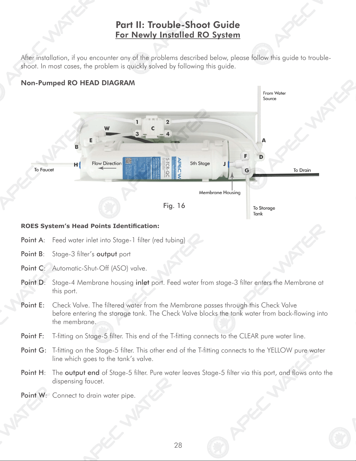
Non-Pumped RO HEAD DIAGRAM
ROES System’s Head Points Identication:
Point A: Feed water inlet into Stage-1 filter (red tubing)
Point B: Stage-3 filter’s output port
Point C: Automatic-Shut-Off (ASO) valve.
Point D: Stage-4 Membrane housing inlet port. Feed water from stage-3 filter enters the Membrane at
this port.
Point E: Check Valve. The filtered water from the Membrane passes through this Check Valve
before entering the storage tank. The Check Valve blocks the tank water from back-flowing into
the membrane.
Point F: T-fitting on Stage-5 filter. This end of the T-fitting connects to the CLEAR pure water line.
Point G: T-fitting on the Stage-5 filter. This other end of the T-fitting connects to the YELLOW pure water
line which goes to the tank’s valve.
Point H: The output end of Stage-5 filter. Pure water leaves Stage-5 filter via this port, and flows onto the
dispensing faucet.
Point W: Connect to drain water pipe.
Fig. 16
29
2) No Water at Dispensing Faucet
- Water supply is off —> Turn on the water supply, or open Needle Valve ( turn needle handle
counter clockwise)
- Tank’s valve is closed —> Turn tank valve to an “Open” position
- Output line is crimped —> Remove crimp
- Incorrect installation —> See Fig.11 (Page 14). Verify all line connections.
- Low tank pre-charge pressure —> Raise tank air pressure to 5-7 psi.
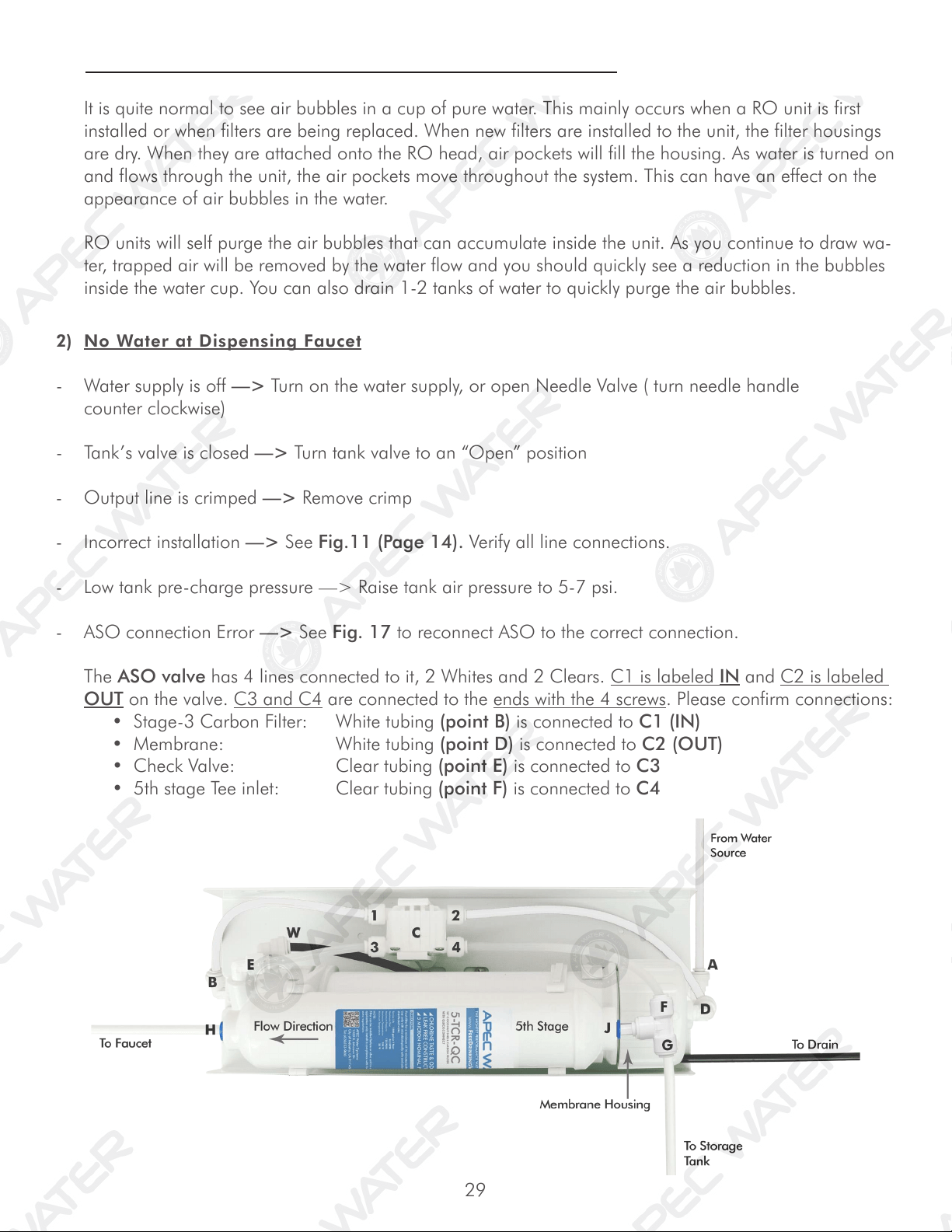
- ASO connection Error —> See Fig. 17 to reconnect ASO to the correct connection.
The ASO valve has 4 lines connected to it, 2 Whites and 2 Clears. C1 is labeled IN and C2 is labeled
OUT on the valve. C3 and C4 are connected to the ends with the 4 screws. Please confirm connections:
•Stage-3CarbonFilter: Whitetubing(point B) is connected to C1 (IN)
•Membrane: Whitetubing(point D) is connected to C2 (OUT)
•CheckValve: Cleartubing(point E) is connected to C3
•5thstageTeeinlet: Cleartubing(point F) is connected to C4
1) Air Bubbles: Lots of Air bubbles in cup or bottle when filling
It is quite normal to see air bubbles in a cup of pure water. This mainly occurs when a RO unit is first
installed or when filters are being replaced. When new filters are installed to the unit, the filter housings
are dry. When they are attached onto the RO head, air pockets will fill the housing. As water is turned on
and flows through the unit, the air pockets move throughout the system. This can have an effect on the
appearance of air bubbles in the water.
RO units will self purge the air bubbles that can accumulate inside the unit. As you continue to draw wa-
ter, trapped air will be removed by the water flow and you should quickly see a reduction in the bubbles
inside the water cup. You can also drain 1-2 tanks of water to quickly purge the air bubbles.
30
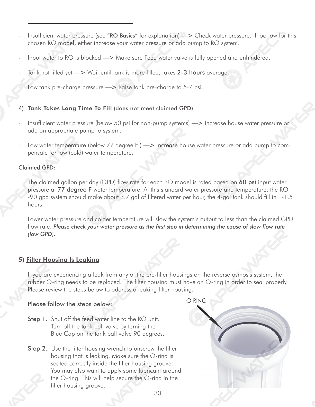
5) Filter Housing Is Leaking
If you are experiencing a leak from any of the pre-filter housings on the reverse osmosis system, the
rubber O-ring needs to be replaced. The filter housing must have an O-ring in order to seal properly.
Please review the steps below to address a leaking filter housing.
Please follow the steps below:
Step 1. Shut off the feed water line to the RO unit.
Turn off the tank ball valve by turning the
Blue Cap on the tank ball valve 90 degrees.
Step 2. Use the filter housing wrench to unscrew the filter
housing that is leaking. Make sure the O-ring is
seated correctly inside the filter housing groove.
You may also want to apply some lubricant around
the O-ring. This will help secure the O-ring in the
filter housing groove.
4) Tank Takes Long Time To Fill (does not meet claimed GPD)
- Insufficient water pressure (below 50 psi for non-pump systems) —> Increase house water pressure or
add an appropriate pump to system.
- Low water temperature (below 77 degree F ) —> Increase house water pressure or add pump to com-
pensate for low (cold) water temperature.
Claimed GPD:
The claimed gallon per day (GPD) flow rate for each RO model is rated based on 60 psi input water
pressure at 77 degree F water temperature. At this standard water pressure and temperature, the RO
-90 gpd system should make about 3.7 gal of filtered water per hour, the 4-gal tank should fill in 1-1.5
hours.
Lower water pressure and colder temperature will slow the system’s output to less than the claimed GPD
flow rate. Please check your water pressure as the first step in determining the cause of slow flow rate
(low GPD).
3) Sluggish Flow At Dispensing Faucet
- Insufficient water pressure (see “RO Basics” for explanation) —> Check water pressure. If too low for this
chosen RO model, either increase your water pressure or add pump to RO system.
- Input water to RO is blocked —> Make sure Feed water valve is fully opened and unhindered.
- Tank not filled yet —> Wait until tank is more filled, takes 2-3 hours average.
- Low tank pre-charge pressure —> Raise tank pre-charge to 5-7 psi.
31
Step 3. Re-attach the filter housing to the RO head. Hand tighten the housing, then use the filter
housing wrench and simply give an additional quarter inch turn. Do Not over tighten the
housing.
Step 4. Open the tank ball valve and feed water line. Check for leaks. If the filter housing continues to
leak, please contact APEC technician for replacement assistance.
- Forgot to insert membrane into its housing —> Put membrane into housing.
- Membrane is inserted incorrectly —> Re-insert membrane correctly. See Fig.14B, page 20.
- Water pressure too low, causing TDS to be higher than usual —> Raise water pressure or add
pump to RO.
- Input source water has very high TDS and/or contains certain heavy dissolved elements resulting in
TDS higher than usual.
- Drain water flow is restricted or clogged —> Check and re-align the drain saddle and drain line.
- Your input water’s TDS fluctuates resulting in high “composite” TDS in the holding tank —> To
verify this, test the filtered water’s TDS before it enters the tank. Do test as follows:
Test #1 TDS from tank: Dispense some water from the RO faucet, this water comes directly from the tank.
Test TDS, record the reading, then Do Test #2.
Test #2 TDS bypassing tank: Turn OFF tank valve. Disconnect the Yellow line from the tank’s valve. A
stream of filtered water will trickle out of the Yellow line. Let the water trickle freely for about 1 minute,
then Catch some water here and do a TDS test. The TDS here is the actual “real time TDS” the RO is
producing before water enters the tank. Compare this TDS reading with the tank’s TDS you get in Test
#1.
If tank TDS is higher than Yellow line TDS, that means your source water’s TDS level fluctuates over time.
So, from day to day, the TDS highs and lows accumulate in the tank resulting in a high “composite TDS”
reading. This is especially true if you’re on a private well. The well pump’s fluctuating pressure cycles
also cause TDS to go up and down. In this case, the “real-time” TDS from the Yellow line (prior to the
tank) is the system’s true performance. If this number is within 10% of your tap TDS, then it is within an
acceptable range, and your RO system is working fine.
Drawing more water can help stabilize the TDS. If you are only drawing a small amount of water every
time, the unit will quickly turn On and Off, not allowing the membrane to receive full inlet pressure,
causing a spike in the TDS.
6) TDS (Total Dissolved Solids) Level Reads Higher Than Normal
How to test TDS correctly: See “TDS Meter -- How to Test Your Water Quality” instructions on page
25.
If the filtered water’s TDS reads higher than the normal 10% range, these are the possible causes:
32
7) There is a leak at the Tank ball valve connection
If you are experiencing a leak from where the tank ball valve attaches to the tank stem, you may not
have applied enough Teflon tape to the stem when you first installed the valve. To correct this issue,
please turn off the supply water to the system and turn on the drinking water faucet to completely empty
the tank. Then, unscrew the tank ball valve and apply 6-8 wraps of Teflon Tape to the tank stem and
screw on the tank ball valve back onto the tank. Please double check the connection for leaks.
8) System Slow Shut-Off: Drain water runs for hours (6-7 hrs) - but Eventually Stops
The most common cause for “slow-shut-off” is insufficient input water pressure. RO needs
sufficient input pressure to shut off promptly.
- Input water pressure too low (below 40psi). Not enough pressure to shut off RO promptly —>
Check input water pressure. If pressure is low, boost house pressure or add pump to RO.
- Feed water valve partially blocked, not opened fully, reducing input water pressure to RO —>
Check and fix feed water valve, make sure it is opened fully to allow maximum pressure to RO.
- Stages 1, 2, 3 pre-filters partially clogged, reducing the input water pressure in RO —> Check stage-1
filter to see if it’s very dirty. If this filter has turned brown or other color in just 1-3 months, that means
your input water has very heavy sediments and other clogging agents. Need to replace stage-1 filter
frequently.
- RO busy feeding multiple output points —> If your RO feeds multiple outlets (icemaker,
bathroom, aquarium), the drain water will run as long as the RO is making water to fill the tank and
other output points. In this case, it’s normal to hear drain water running.
NOTE: Very cold tap water temperature may cause slower shut off
9) System Does Not Shut-Off: Drain water runs all day - and Never Stops
- Input pressure way too low (below 30psi). Not enough pressure to shut off the RO at all —> Check in-
put water pressure. If pressure is below 30psi, need switch to Booster-Pumped RO model. Contact APEC
customer service for assistance.
- One of the shut-off valves are defective, so RO cannot shut off —> Do a shut-off test to determine
which valve is defective. Do test as shown below.
33
10) How to Test RO’s Shut-Off Function:
The RO system should shut off automatically when the tank is filled. When the RO fails to shut off after
tank is filled, drain water will keep running down the drain depleting the pre-filters, the membrane, and
may lead to higher water bills. To test if your RO system is shutting down normally, please follow the
steps below.
- Draw 3-4 glasses of water from spigot. RO will start making water to fill tank.
- Turn OFF the blue tank ball valve on top of the water storage tank clockwise 90 degrees to
mimic a full tank.
- If your RO feeds multiple output points (icemaker, bathroom, etc), please use a manual shut
off valve to shut OFF water to those lines.
- Wait up to 10 minutes, then check to see if the drain water starts slowing down to a stop.
- Check drain water by pulling the black drain tubing out from the drain pipe and let water flow
into a good size bucket to view it.
- If drain water stops running --> The RO is shutting off properly no additional test is needed.
- If drain water continues to run after 10 minutes --> it could be caused by the following:
a. Insufficient or low water pressure.
b. Colder tap water during winter seasons.
c. System part or filter not working correctly.
Please contact an APEC Product Specialist at your earliest convenience to help take care of this
issue quickly.
11) Pure water still tastes like Tap water:
If the RO system is newly installed, please make sure the first 1-2 tanks of water have been completely
flushed out. The new filters on your system needs to be flushed out before use.
Once the tank has been fully filled and flushed 1-2 times, use the TDS meter to check the tap water vs.
pure water TDS. With good water pressure and normal water quality, our RO units are designed to re-
move 90-99% of total dissolved solids impurities from water. Please contact an APEC product specialist
if you have any questions or need assistance.
34
Tilt
System
Check
Valve
Close
Tank
Valve
If the noise comes back, try the above procedure again another 2-3 times. Sometimes it takes several
tries to get rid of all the air in the system.
If the noise persists after a few days, that means there is air in your water source, or the current Check
Valve is resonating with your water pressure and pipes, creating the noise.
In this case, a new Check Valve will solve the problem. Contact APEC customer service for assistance.
* * * End Trouble-Shoot Guide * * *
Fig. 18
Step 1 Step 2 Step 3
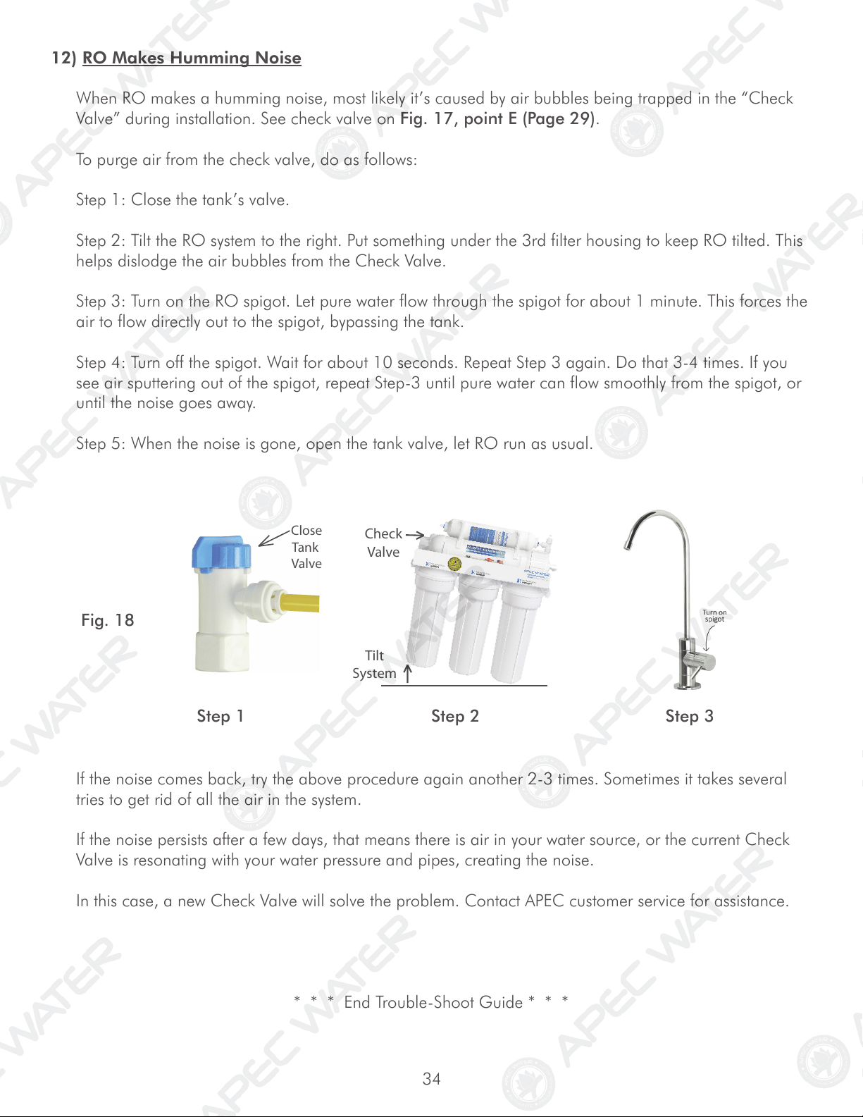
12) RO Makes Humming Noise
When RO makes a humming noise, most likely it’s caused by air bubbles being trapped in the “Check
Valve” during installation. See check valve on Fig. 17, point E (Page 29).
To purge air from the check valve, do as follows:
Step 1: Close the tank’s valve.
Step 2: Tilt the RO system to the right. Put something under the 3rd filter housing to keep RO tilted. This
helps dislodge the air bubbles from the Check Valve.
Step 3: Turn on the RO spigot. Let pure water flow through the spigot for about 1 minute. This forces the
air to flow directly out to the spigot, bypassing the tank.
Step 4: Turn off the spigot. Wait for about 10 seconds. Repeat Step 3 again. Do that 3-4 times. If you
see air sputtering out of the spigot, repeat Step-3 until pure water can flow smoothly from the spigot, or
until the noise goes away.
Step 5: When the noise is gone, open the tank valve, let RO run as usual.

35
36
OTHER INFORMATION
AirGap Faucet Installation (Optional)
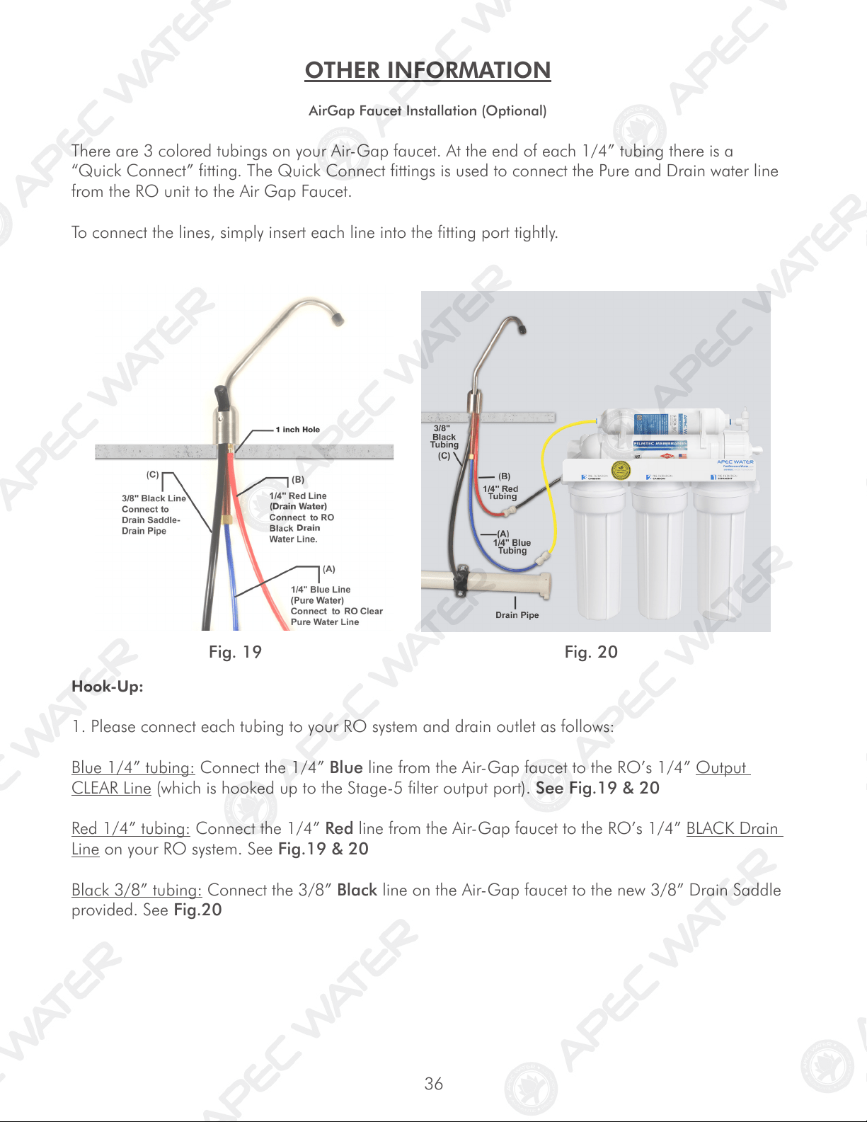
There are 3 colored tubings on your Air-Gap faucet. At the end of each 1/4” tubing there is a
“Quick Connect” fitting. The Quick Connect fittings is used to connect the Pure and Drain water line
from the RO unit to the Air Gap Faucet.
To connect the lines, simply insert each line into the fitting port tightly.
Hook-Up:
1. Please connect each tubing to your RO system and drain outlet as follows:
Blue 1/4” tubing: Connect the 1/4” Blue line from the Air-Gap faucet to the RO’s 1/4” Output
CLEAR Line (which is hooked up to the Stage-5 filter output port). See Fig.19 & 20
Red 1/4” tubing: Connect the 1/4” Red line from the Air-Gap faucet to the RO’s 1/4” BLACK Drain
Line on your RO system. See Fig.19 & 20
Black 3/8” tubing: Connect the 3/8” Black line on the Air-Gap faucet to the new 3/8” Drain Saddle
provided. See Fig.20
Fig. 19 Fig. 20
37
How drain water is disposed via Air-Gap faucet:
Drain water is routed through the Air-Gap faucet prior to being drained off into the standard drain-
pipe outlet. The 1/4” BLACK drain water line from the RO system will discharge through the 1/4”
RED line to the Air-Gap faucet. The drain water will then flow back down the 3/8” BLACK drain
water line of the Air-Gap faucet to your drain pipe.
Pure water output flow:
After the Air Gap faucet is installed, the RO pure water output line will flow from the Stage-5 filter,
through the BLUE line of the Air-Gap faucet, to the dispensing faucet.
* * * End AirGap Faucet Installation * * *
38
LIMITED PRODUCT WARRANTY
Scope
APEC takes pride in selling a superb line of products, including this reverse osmosis system (“Product”). As such, APEC expressly
warrants to the original purchaser that, for a period of one (1) year from the date of purchase, the Product will be reasonably free of
defects in materials and workmanship. Within that one (1) year period from the original purchase, APEC will, at its option, repair or
replace the Product without charge, or refund the cost of the Product, if the Product fails or does not perform as warranted solely due
to a manufacturing defect within the warranty period, subject to the limitations and exclusions set forth in this Limited Product War-
ranty. This Limited Product Warranty only applies when the Product is used, stored, handled, fabricated and/or installed in the manner
recommended by APEC in the Installation Instruction & Owner’s Manual (“Manual”).
Repair or Replacement
Repair or replacement during this one (1) year warranty shall include reasonable labor charges necessary to repair or replace the de-
fective Product, but shall not include freight charges or any other local labor charges from third parties other than APEC, unless APEC
expressly approves such charges in writing. During the entire one (1) year warranty, APEC’s obligation to repair or replace shall further
be limited to repair or replacement with the styles, models, products, colors, etc. of the Product that are available at the time of the
repair or replacement, and shall be limited to the repair or replacement of only the specific Product that fails due to a manufacturing
defect. Any repaired or replaced product shall also remain subject to the original one (1) year warranty from the date of the original
purchase, and any repair or replacement shall not extend the original warranty period in any manner or start a new warranty period.
Conditions of Validity of this Limited Product Warranty
Even though the Product has extremely high endurance for operating conditions such as pH, maximum TDS, temperature, and opti-
mum water pressure, THIS LIMITED PRODUCT WARRANTY SHALL ONLY BE VALID IF:
1. The replaceable filters and membrane are changed and maintained on a regular basis as directed in the Manual. Moreover,
depending on local water input water quality, regular maintenance may need to be increased.
2. The Product is operated within the confines of the following standard operating conditions:
Water Pressure pH Range Max. TDS Water Temperature
Standard System 40- 85 psi 2-11 2000 ppm 40-100 ºF
Permeate Low Pressure System 30- 85 psi 2-11 2000 ppm 40-100 ºF
Booster Pumped System 0- 30 psi 2-11 2000 ppm 40-100 ºF
Any information or suggestion by APEC with respect to the Product concerning applications, specifications or compliance with codes
and standards is provided solely for your convenient reference and is made without any representation as to accuracy or suitability. You
must verify and test the suitability of any information with respect to the Product for your specific application.
Non-Covered Defects
THIS LIMITED PRODUCT WARRANTY DOES NOT COVER DEFECTS CAUSED BY:
1. Improper storage, installation, maintenance, handling, use and/or alterations of the Product, including, but not limited to, non-
compliance with the installation, maintenance and standard operation conditions stated in the Manual and this Limited Product
Warranty.
2. Unreasonable use, unintended use, or misuse of the Product for something other than its intended purpose as a reverse osmosis
system.
3. Use of replacement parts, filters, membranes or other accessories that are not sold or manufactured by APEC for use with this
particular Product.
4. Damage not resulting from manufacturing defects that occur while the Product is in the original purchaser’s possession.
5. Installation of the Product with known or visible manufacturing defects at the time of installation.
6. Damage caused by freezing, flood, fire or Act of God.
39
CONDITIONS THAT RENDER THIS LIMITED PRODUCT WARRANTY VOID
THIS LIMITED PRODUCT WARRANTY SHALL BE VOID IF:
1. The Product is not operated in compliance with normal municipal water conditions for which the particular model of this Product
is intended.
2. The person seeking to invoke the warranty is not the original purchaser. That is, this Limited Product Warranty only extends to
original purchasers.
3. The product is purchased used. That is, this Limited Product Warranty only covers new products.
4. The Product is purchased from someone other than APEC or one of APEC’s authorized dealers. This is because, unless the
Product was sold by APEC or one of its authorized dealers, APEC cannot verify or guarantee the integrity or authenticity of the
Product.
General Conditions
The warranties set forth herein are the only warranties made by APEC in connection with the product. APEC cannot and
does not make any implied or express warranties with respect to the product, and disclaims all other warranties, includ-
ing, but not limited to, any warranty of merchantability or fitness for a particular purpose. Products sold by APEC are
sold only to the specifications specifically set forth by APEC in writing. Other than the limited product warranty set forth
herein, APEC makes no other warranties, express or implied. APEC’s sole obligation under this warranty shall be repair
or replacement of a non-conforming product or parts of the product, or at the option of APEC, return of the product and
a refund of the purchase price. Buyer assumes all risk whatsoever as to the result of the use of the product purchased,
whether used singularly or in combination with any other products or substances.
No claim by the buyer/owner of any kind, including claims for indemnification, shall be greater in amount than the
purchase price of the products in respect to which damages are claimed. In no event shall APEC be liable to buyer/owner
in tort, contract or otherwise, for any special, indirect, incidental, consequential, reliance, statutory, special, punitive or
exemplary damages, including, but not limited to, lost profits, loss of use, loss of time, inconvenience, damage to good
will or reputation, or loss of data, even if advised of the possibility of such damages or such damages could have been
reasonably foreseen, in connection with, arising out of, or as a result of, the sale, delivery, servicing, use or loss of use of
the products sold hereunder, or for any liability of buyer to any third party with respect thereto.
Obtaining Warranty Coverage or General Inquiries
If coverage is available, you may obtain coverage under this Limited Product Warranty by providing APEC with proof of original
purchase, and that you are the original purchaser. For service under this Limited Product Warranty, you must notify APEC by phone at
1-800-880-4808, by email at techsupport@freedrinkingwater.com, or in writing at 1320 S. Johnson Dr., City of Industry, CA 91745.
In making the claim, please provide your name, address, phone number, a description of the product involved, and an explanation of
the defect.
California Proposition 65 Warning
WARNING: This product contains chemicals known to the State of California to cause cancer or birth defects or other
reproductive harm. For more information go to www.P65Warnings.ca.gov.

Advanced Purification Engineering Corp.
1320 S Johnson Drive
City of Industry, CA 91745
For questions or comments please visit our website at:
www.FreeDrinkingWater.com
For technical support contact us at:
Techsupport@freedrinkingwater.com
1-800-880-4808