REVERSE OSMOSIS
DRINKING WATER SYSTEM
INSTALLATION GUIDE AND OWNER’S MANUAL

Congratulations on choosing a superior reverse osmosis unit for your tap!
This installation and owner’s manual details the standard installation, care and maintenance,
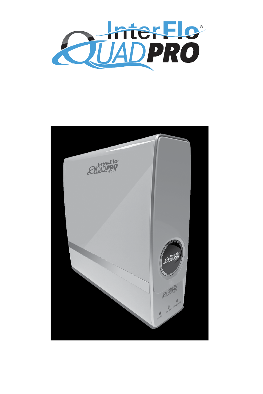
and general operating instructions for the QuadPro SST reverse osmosis system.
TABLE OF CONTENTS
Pre-Installation
.........................................................................
3
Installation
...............................................................................
5
Care & Maintenance
..................................................................
11
Troubleshooting
.......................................................................
13
Additional Installation Conguration
..............................................
14
Performance Data
....................................................................
15
Limited Warranty
......................................................................
18
Cartridge Replacement Checklist
..................................................
19
3
PRE-INSTALLATION
The InterFlo QuadPro SST is a sophisticated, tankless reverse osmosis unit designed to provide drinking water
on demand. The contents in the box includes everything that you will need to complete a standard, below-the-
sink installation with the included dispensing e-faucet. Additionally, a pressure transducer has been included to
accommodate installations for un-powered faucets. Installations that differ from the below-the-sink method are
not covered in this guide, but are possible.
Please keep this guide for reference following installation.
Dealers and Installers: Read and reference installation instructions prior to installation.
Owners: Understand the lter replacement schedule and how to read the cartridge life indicator lights on the
front of the unit.
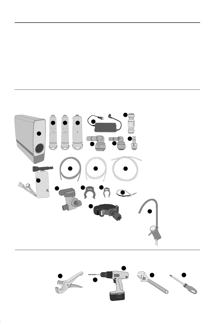
BOX CONTENTS:
Ensure that all of the following components are included in the box prior to installation.
A. QUADPRO SST REVERSE OSMOSIS
UNIT (1)
B. PRE-FILTER CARTRIDGE (1)
C. POST-FILTER CARTRIDGE (1)
D. RO CARTRIDGE (1)
E. POWER TRANSFORMER (1)
F. 3/8” FITTING ELBOW (3)
G. 1/4” FITTING ELBOW (1)
H. 1/4” STRAIGHT FITTING (3)
I. CHECK VALVE
J. RED 1/4” DRAIN TUBING (1)
K. WHITE 1/4” TUBING (1)
L. WHITE 3/8” PRODUCT WATER TUBING (2)
M. LARGE LOCKING CLIP (3)
N. SMALL LOCKING CLIP (1)
O. ZIP TIE (5)
P. PRESSURE TRANSDUCER (1)
Q. JOHN GUEST VALVE (1)
R. DRAIN INSTALLATION CLAMP (1)
INCLUDES 2 ADHESIVE PADS
S. E-FAUCET ASSEMBLY (1)
A
B C D
F
E
H
I
G
KJ
L
M
N
O
P
Q
R
S
NECESSARY TOOLS:
The following tools are recommended for a standard installation.
● Tube Cutter (a)
● Battery Powered Drill (b)
● 1/4” Drill Bit (c)
● Adjustable Wrench (d)
● Phillips Screwdriver (e)
● Pencil
● 2.5mm Allen Wrench
a
d
c
b
e
4
PRE-INSTALLATION
SITE PREPARATION:
The QuadPro SST is designed for an under-sink installation. In cases of space limitations or if an under-sink
installation is not possible, the unit may be installed in other locations. Some considerations when choosing a
location include:
● Close proximity to a cold water tap line.
● Close proximity to a suitable drain.
● Accessibility to a non-switched outlet. The outlet must provide consistent power to activate when the faucet is
turned on.
● Accessibility for lter cartridge replacements. Cartridges must be changed out on a regular schedule.
● The location must meet temperature requirements. Components must not be exposed to freezing
temperatures.
PRECAUTIONS:
● Do not disassemble or modify the unit. If interior components need repair or maintenance, contact the
manufacturer.
● Installation should only be carried out by authorized professionals.
● Do not place the unit near a heat source.
● Do not use power beyond the rated value of the machine. Only use the included AC power adapter.
● Keep the device unplugged when performing maintenance or installing.
● Do not install the unit outdoors or in direct sunlight.
● DO NOT USE WITH WATER THAT IS MICROBIOLOGICALLY UNSAFE OR OF UNKNOWN QUALITY,
WITHOUT ADEQUATE DISINFECTION BEFORE OR AFTER THE SYSTEM.
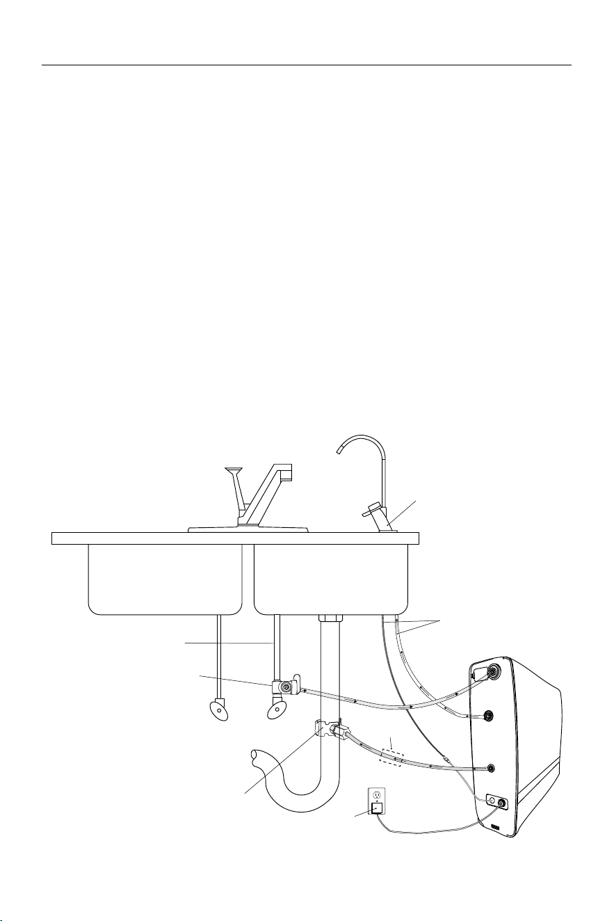
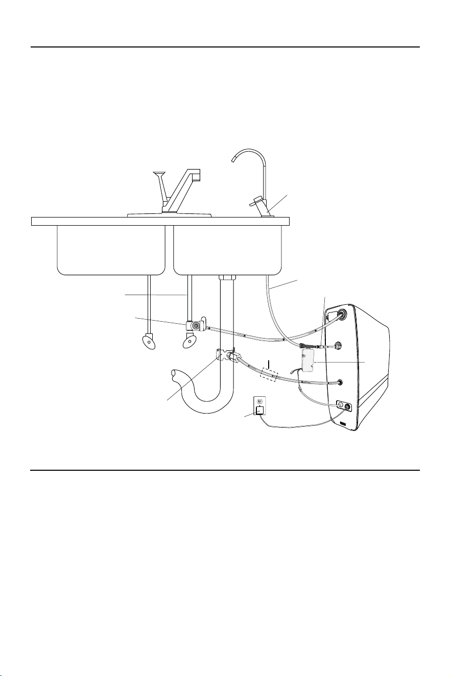
INSTALLATION DIAGRAM:
With included E-Faucet
E-Faucet
Feed Water
To E-Faucet
Pure
Water
Drain
Water
Power Connection
Drain Adapter
John Guest Valve
Cold Water Line
P
r
o
p
e
r
l
y
A
i
r
G
a
p
F
o
r
L
o
c
a
l
C
o
d
e
s
*Install Air Gap
*Air gap must be two pipe diameters or 1 inch (25mm), whichever is larger.
5
INSTALLATION
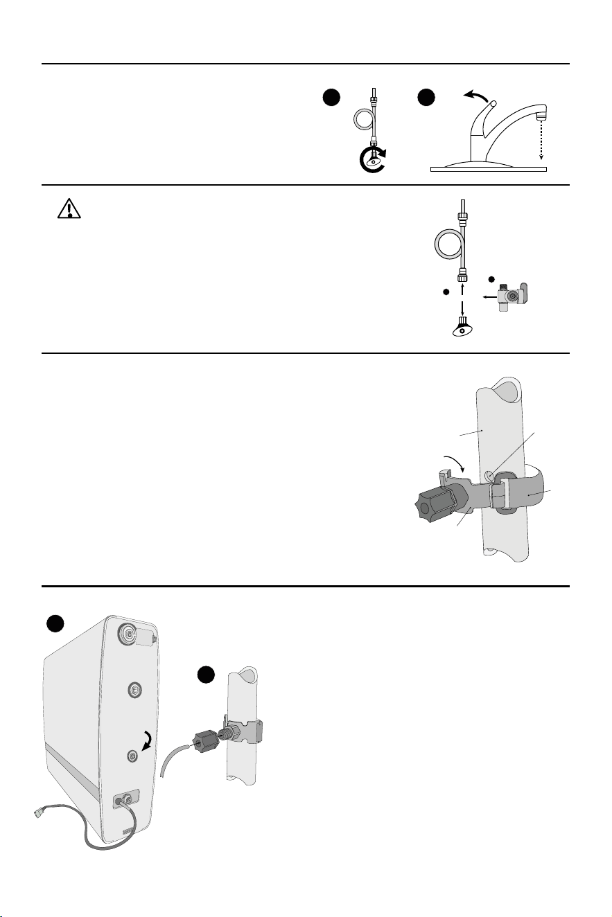
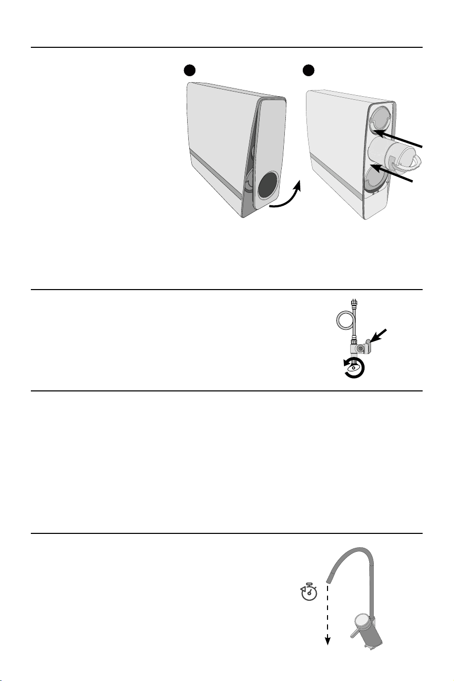
1 SHUT OFF COLD WATER SUPPLY
Shut the cold water supply off beneath the sink by
hand-rotating the shutoff handle clockwise until fully
closed. Open the cold water tap to relieve water
pressure.
2 DISCONNECT WATER SUPPLY AND ATTACH JOHN GUEST VALVE
Using an adjustable wrench, disconnect the cold water supply from the
shutoff valve.
Attach the John Guest valve to the cold water shutoff in the orientation
shown on the right Once installed, attach the cold water line to the threaded
top of the John Guest valve.
3 PREPARE DRAIN CLAMP
Choose a location on the sink’s drain pipe that is unobstructed and above the
drain trap. Ensure that this location is easy to access and can accommodate
drilling. The waste water must go to drain through an anti-siphon air gap.
Mark a location on the drain pipe and, using a battery powered drill
equipped with a 1/4” bit, drill a hole into the wall of the drain pipe. TAKE
CARE TO NOT PENETRATE THE OPPOSITE SIDE OF THE PIPE.
Affix an adhesive pad over the rear of the outlet on the drain clamp
assembly. Position the drain clamp assembly over the newly drilled hole
and line up the hole with the clamp’s outlet. When lined up properly, rmly
press the clamp to the drain pipe and attach the Velcro strap tightly.
4 CONNECT DRAIN LINE
Insert one end of the 1/4” red drain line to the quick connect
drain outlet on the rear of the QuadPro SST RO Unit. Run the
other end to the drain clamp installed in step 3.
Using a tube cutter, cut the red drain line to length. Ensure that
there is little to no sag in the drain line to prevent noise and
thrashing while the unit is draining.
Remove the nut from the drain clamp and run the second end of the
red drain line through the hole in the nut, into the installed drain clamp
assembly, and into the hole cut into the drain pipe. Hand tighten the
nut with the drain line back into the drain clamp assembly.
I
nstall an air gap on the drain line. This must be installed
between the system and the drain adapter. Air gap not included
in this system.
1 2
Disconnect
Install
1
2
Drain Pipe
Apply Adhesive
Pad to rear of drain
clamp
Velcro
Strap
Drill 1/4”
Hole
Drain Clamp
I
N
S
E
R
T
R
E
D
D
R
A
I
N
L
I
N
E
1
2
Insert Red
Drain Line
Remove four screws from bottom plate before installation.
6
INSTALLATION
5 INSTALL FAUCET
If installing the e-faucet included with the QuadPro SST unit, proceed to page 8 and return to step 6 once complete.
If installing a different faucet, if replacing an existing RO unit and will be using the existing faucet, or if using
the reverse osmosis unit for a different application than a dispensing faucet (such as an ice maker), please
reference page 9.
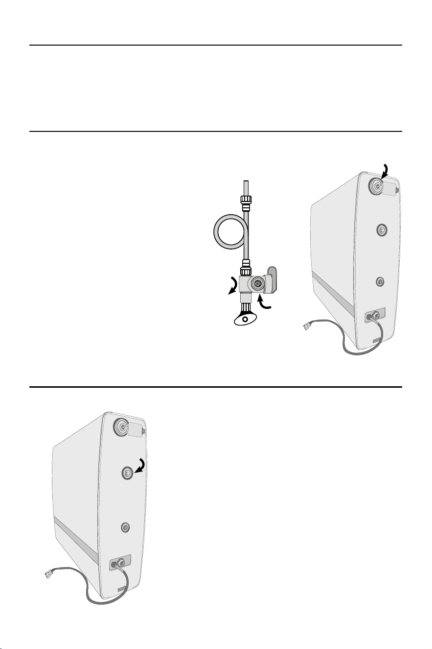
6 MAKE FEED WATER CONNECTION
Connect one end of a 3/8” White Product Water
Tubing into the quick-connect port on the
previously installed John Guest Valve. Run the
other end of the tubing to the QuadPro SST
reverse osmosis unit, approximately close to
where its nal position will be. Using a tube cutter,
cut the tubing to a desired length. Use included
tting installation elbows as needed.
7 MAKE PRODUCT WATER CONNECTION
Connect one end of a 3/8” White Product Water Tubing
into the connection on the faucet. Run the other end of
the tubing to the QuadPro SST reverse osmosis unit,
approximately close to where its nal position will be. Using
a tube cutter, cut the tubing to a desired length. Use tting
installation elbows as needed.
Insert White
3/8” Tubing
Insert White
3/8” Tubing
Insert White
3/8” Tubing
7
INSTALLATION
9 CONNECT TRANSFORMER AND TEST FOR LEAKS
Connect the power transformer to the connection on the QuadPro SST. Turn the
cold water supply on by hand rotating the shutoff valve handle in the counter-
clockwise direction and ensure the John Guest valve will allow ow to the unit.
Check for leaks around the raw water connections, including the John Guest
valve and the raw water input on the unit.
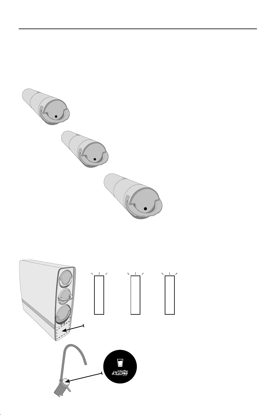
8 INSERT FILTRATION CARTRIDGES
Remove the front faceplate of the
unit by lifting up on the bottom of the
magnetized faceplate connector and
pulling upwards. Set aside the faceplate.
Insert the replacement cartridges into
the unit in the order shown by pressing
the cartridge until an audible “click”
sound is heard. Ensure that the handle
is in the “locked” position. Repeat with
the remaining cartridges.
Top: Pre-Filter Cartridge
Middle: Post-Filter Cartridge
Bottom: RO Cartridge
NOTE: Filtration cartridges may come pre-installed in the unit. In this case, remove each cartridge and
inspect for any packaging. Re-install each cartridge once it is conrmed that no packaging is present
on the cartridge or in the cartridge port.
10 PLUG UNIT IN TO POWER SOURCE
Plug unit into the designated power supply. The pump will begin to run and will initiate its startup cycle. During
startup, water will run to the drain. The startup cycle will last for approximately sixteen minutes. Once the pump
stops making noise and water stops running to the drain, the startup cycle is complete.
Ensure that the indicator lights are white for each lter cartridge. For more information on the indicator lights,
see page 11.
NOTE: Prior to plugging unit in, ensure that all water connections have been made and are secure.
Plugging the unit in activates the pump and may result in signicant water leakage if all connections
are not made.
11 CLEAR WATER LINE
Turn the RO faucet on and let run for a full fteen minutes. Ensure
that no air pockets are observed following the fteen minutes of
run-time.
Once complete, shut off the RO faucet and do a nal check for
leaks, inspecting each of the connections. If no leaks are present,
position the unit in its nal location.
LIFT AND
PULL UP
1 2
John Guest
Valve Handle
should be in the
“up” position
15 mins
8
INSTALLATION
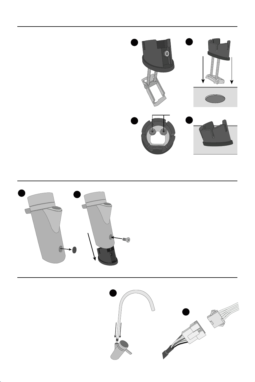
1 INSTALL FAUCET BASE ASSEMBLY
Using a 2.5mm Allen wrench, remove and set aside
the hex bolt on the rear of the faucet base assembly.
If the sink does not have an existing 0.8-1.2 inch hole
pre-drilled, such as for an existing spray attachment
hole, the sink top will need to be drilled.
Note: If the sink has a pre-drilled hole of a larger
diameter than instructed to drill herein
(0.8-1.2 inch), it is necessary to purchase
a suitable escutcheon or cover plate
adequate for the pre-drilled hole. Such
a part/kit is not included in the IAPMO
certication of this system to CSA B483.1
Insert the faucet base assembly into the designated
hole on the sink top. Orient the faucet base assembly
so its rear (where the hex bolt was removed) is facing
away from the sink.
2 INSTALL FAUCET ONTO BASE ASSEMBLY
Remove the rubber screw cap from the rear of
the faucet and set aside. Insert the power cord
connected to the faucet through the center of the
faucet base assembly. Slide the faucet onto the
base assembly in the orientation shown and push
down until fully inserted.
Using a 2.5mm Allen wrench, insert and tighten the
hex screw into the faucet base assembly. Replace
the rubber screw cap.
3 CONNECT FAUCET AND POWER
Insert the faucet neck into the faucet
handle. Push down until the faucet neck is
seated properly.
Connect the power cord that was previously
run through the faucet base to the power
cord on the rear of the RO unit.
Following power connection, the faucet
installation is complete. Return to step 6
on page 6.
1
2
3
4
Tighten
1
2
a.
b.
1
2
RO UNIT
FAUCET
Using a Phillip’s screwdriver, tighten the two screws visible on the top of the faucet base assembly.
Once the screws are tightened, the faucet base assembly should rest snugly, without any “give” or movement.
9
INSTALLATION
PRESSURE TRANSDUCER INSTRUCTIONS (OPTIONAL)
The included powered faucet communicates with the QuadPro SST unit in one important way.
● It signals the reverse osmosis unit to turn on the pump when the tap is opened.
For installations that are not using the included dispensing faucet, a pressure transducer has been included.
This transducer replaces the rst function of the QuadPro SST faucet by turning on the pump when water is
drawn through it. The following instructions detail the installation of the transducer only.
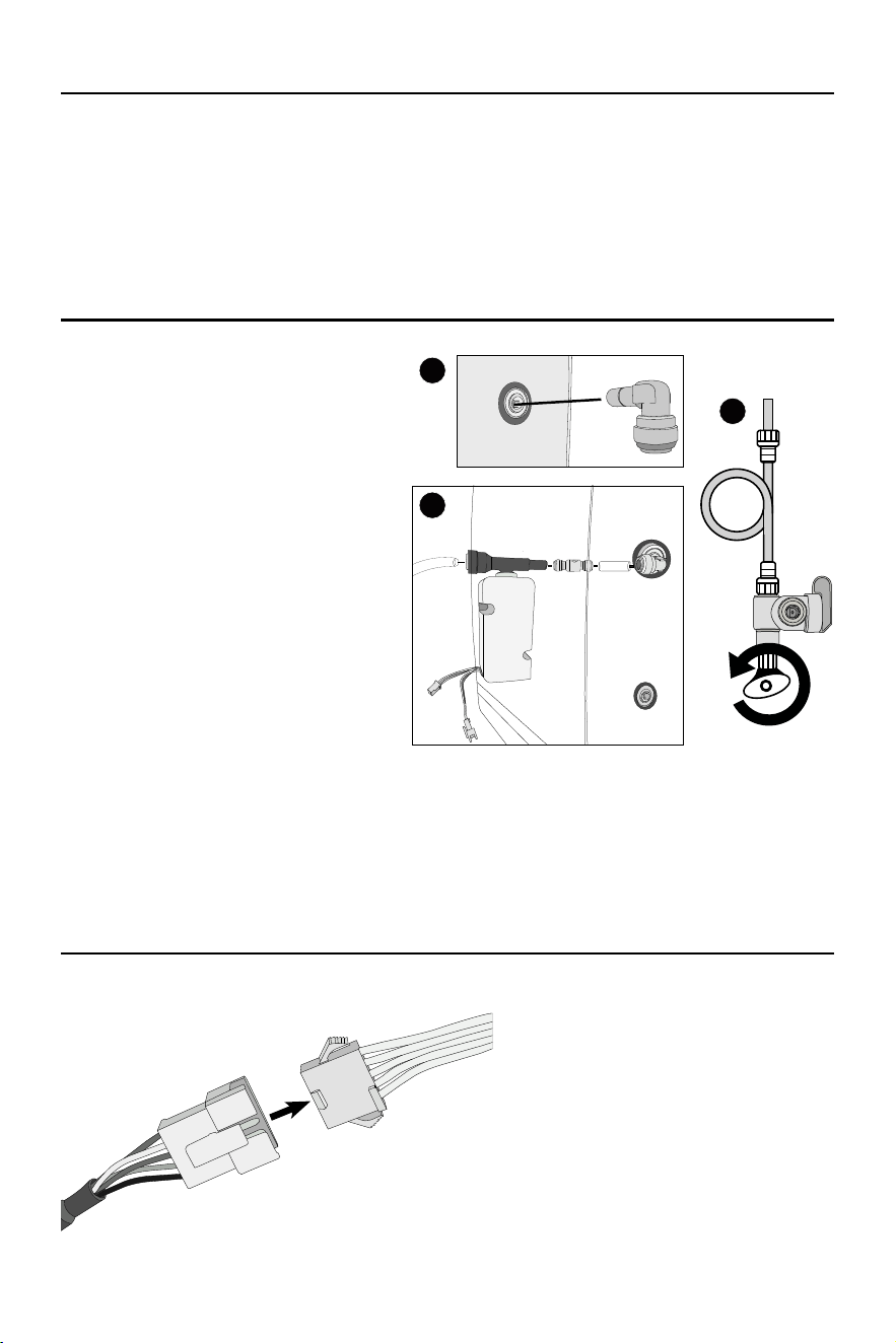
1 CONNECT THE PRESSURE TRANSDUCER
Ensure that the unit is not connected to a power
source.
Insert an included 3/8” tting elbow into the pure
water quick connect port on the rear of the unit.
Insert an end of 3/8” white product tubing into
the tting elbow and cut the other end to length
(it is recommended to keep this line between
10 - 12 inches).
Insert the other end of tubing into the included
check valve (ensure that the arrow on the check
valve is facing away from the unit and towards
where the pressure transducer will be added).
Insert the 3/8” end of the pressure transducer
into the check valve.
Insert the 3/8” tubing connected to the faucet
into the end of the pressure transducer.
Turn the cold water supply on by hand turning
the shutoff valve in the counter-clockwise
direction. Check for leaks in the pressure
transducer connections.
2 CONNECT POWER SUPPLY
Insert the power connector on the rear of the
RO unit into the corresponding connector on
the pressure transducer.
1
2
3
RO UNIT
PRESSURE TRANSDUCER
10
INSTALLATION
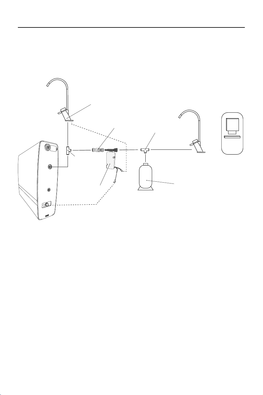
Feed Water
Pure
Water
Drain
Water
Faucet
(Non E-Faucet)
Pressure Transducer
To Faucet
Power Connection
Drain Adapter
John Guest Valve
Cold Water Line
Check Valve
*Install Air Gap
P
r
o
p
e
r
l
y
A
i
r
G
a
p
F
o
r
L
o
c
a
l
C
o
d
e
s
INSTALLATION DIAGRAM WITH PRESSURE TRANSDUCER
3 MOUNT THE PRESSURE TRANSDUCER
With all of the connections made, the pressure transducer may be mounted on the
side of the unit using the included adhesive pad (recommended).
Installation is now complete. Continue to step 7 on page 6.
4 CHECK ELECTRICAL REQUIREMENTS
This system requires the following voltage and frequency: 120V/60Hz. Please ensure
it is connected to an outlet.
*Air gap must be two pipe diameters or 1 inch (25mm), whichever is larger.
11
CARE AND MAINTENANCE
FILTRATION CARTRIDGES
Filtration cartridges must be replaced regularly in order to maintain a consistent output of quality water.
The information below details the purpose of each component and gives a general replacement schedule
through normal recommended use.
Recommended replacement schedules may vary depending on the quality of the untreated input water, the
presence of water pre-treatment equipment, or volume of water used.
CARTRIDGE LIFE INDICATOR
The QuadPro SST unit features indication lights which signal the need for cartridge replacement. These
lights may be observed on the front of the unit in the position shown below. The included E-Faucet also has a
cartridge life indicator. The signals are as follows:
PRE-COMPOSITE
CARTRIDGE
POST-COMPOSITE
CARTRIDGE
RO
CARTRIDGE
PRE-COMPOSITE FILTER
Reduces precipitated matter from water, such as rust, sediment, chlorine, and
other materials.
Replace every 12 months.
POST-COMPOSITE FILTER
“Polishes” water after running through the reverse osmosis
membrane. Reduces odors and improves taste of water.
Replace every 12 Months
REVERSE OSMOSIS MEMBRANE
Reduces common chemical
contaminants
Replace every 48 Months
WHITE LIGHT - Indicates
that the cartridge is in normal,
working order.
ORANGE LIGHT - Indicates
that the cartridge is nearing the
need for replacement.
RED LIGHT - Indicates that the
cartridge has expired and must
be replaced.
1
Sediment
Carbon
Pre-Filter
Carbon
Post-Filter
2
RO
MEMBRANE
3
REPLACEMENT FILTERS & PARTS
Contact your local dealer for replacement lters and
parts, or contact Water-Right (1-800-777-1426) for
the dealer nearest you.
12
CARE AND MAINTENANCE
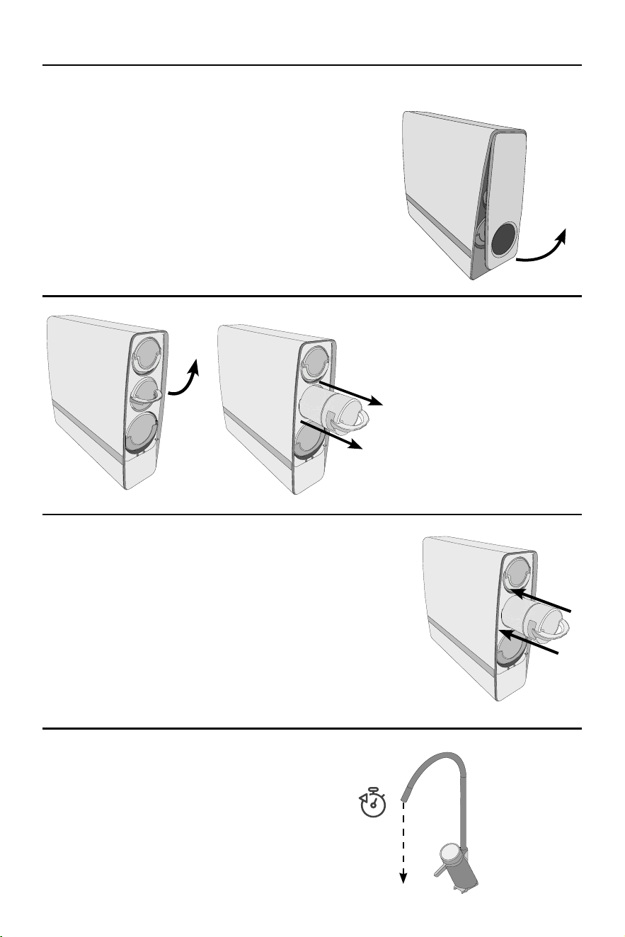
1 REMOVE FACEPLATE
Ensure that the reverse osmosis unit is still plugged in and powered
up. Remove the front faceplate of the unit by lifting up on the bottom
of the magnetized faceplate connector and pulling upwards. Set aside
the faceplate.
Upon removing the faceplate, wait for approximately one minute for
the unit to discharge pressure. The cartridge indicator will ash while
de-pressurization occurs. Once the indicator has stopped ashing,
move to the next step.
2 REMOVE CARTRIDGE
Lift the handle on the cartridge in need
of replacement until it is fully horizontal
to unlock the cartridge. The cartridge will
make a “click” sound once disengaged
using the handle. Pull the cartridge out
of the unit and discard.
Note: Disengaging the cartridge lock
via the handle may require some force.
Lift rmly on the handle to disengage.
3 INSTALL NEW CARTRIDGE
Remove the counter-t protection sticker on the cartridge to reveal the
verication decal underneath.
Insert the replacement cartridge into the unit by pressing the cartridge
until an audible “click” sound is heard. Observe the cartridge indicator and
wait until the indication light turns white for the cartridge that has been
replaced. Once the indicator light turns white, replace the faceplate.
Note: If the indicator light does not turn white after replacing the
cartridge, remove the cartridge and reinstall.
4 TEST WATER FLOW
Turn on the e-faucet and check water ow.
Following replacement of the pre-composite lter or the
post-composite lter, turn on the e-faucet and let run
for fteen minutes prior to use.
FILTER CARTRIDGE REPLACEMENT INSTRUCTIONS
LIFT AND
PULL UP
RAISE
HANDLE
15 mins

13
PROBLEM
CAUSE
CORRECTION
The unit does not start.
A. The power is not connected.
A. Ensure that the power transformer is rmly
plugged into the rear of the unit and connect
-
ed to the power supply.
B. The front cover plate is not installed
or is not installed in place.
B. Remove and reinstall correctly. Check that the
bottom magnets of the cover are engaged.
C. The inlet solenoid valve is faulty.
C. Contact manufacturer for repair or replace
-
ment.
D. The power adapter is faulty.
D. Check power adapter for damage and
replace if required.
E. The main board has no output
voltage.
E. Check output voltage and contact manufac
-
turer for repair or replacement if required.
Low or no puried water
ow from the unit.
A. The post-composite lter cartridge
is blocked.
A. Replace the post-composite lter cartridge.
B. The reverse osmosis lter cartridge
is blocked.
B. Replace the reverse osmosis lter cartridge.
C. Inlet water solenoid valve has failed.
C. Contact manufacturer for repair or replace
-
ment.
D. Pump loses pressure.
D. Contact manufacturer for repair or replace
-
ment.
E. The lter screen in the feed water
port is blocked.
E. Clean or replace the lter screen if required.
The faucet screen does
not display.
A. The faucet cable is not connected.
A. Examine and reconnect faucet power
connections.
B. The faucet display has failed. B. Replace the faucet.
Pump works normally but
no puried water ows
from unit.
A. Pump loses pressure.
A. Contact manufacturer for repair or replace
-
ment.
B. Inlet water solenoid valve has failed (no
pure and drain water at the same time).
B. Contact manufacturer for repair or replace
-
ment.
C. The post-composite lter cartridge
is blocked.
C. Replace the post-composite lter cartridge.
D. The reverse osmosis lter cartridge
is blocked.
D. Replace the reverse osmosis lter cartridge.
E. The main board is faulty.
E. Contact manufacturer for repair or replace
-
ment if required.
No puried water
production but water still
ows to drain.
A. The inlet solenoid valve is faulty. A. Contact manufacturer for repair or replacement.
When unit is powered on
and the faucet is opened,
no water is produced, the
screen ashes, and the
buzzer alarms.
A. The front cover plate is not installed
or is not installed in place.
A. Remove and reinstall correctly. Check that the
bottom magnets of the cover are engaged.
B. The front cover plate has lost a
magnet piece.
B. Examine the front cover and ensure that both
magnet pieces are in place.
C. Inductive sensor is faulty or not
installed in place.
C. Contact manufacturer for repair or replace
-
ment.
Following installation and
rst time powering on,
the faucet logo displays a
red icon.
A. Water has come in contact with
faucet cable connection terminal.
A. Blow dry the faucet cable connection
terminal.
B. Faucet cable is not connected in
place or is faulty.
B. Inspect and reconnect faucet connections or
Contact manufacturer for repair or replacement.
TROUBLESHOOTING
14
ADDITIONAL INSTALLATION CONFIGURATION
The Quadpro SST includes components for an under-sink installation in conjunction with its included E-Faucet.
Additional installation congurations are possible, but should only be performed by professional installers.
The diagram below details an alternative installation conguration for installation of a second, non E-faucet or
ice maker.
Pressure Transducer
E-Faucet
T Connector
(Not Included)
Check Valve
Tank
(optional, not included)
Non E-Faucet
(Not Included)
Ice Maker
OR
T Connector
(Not Included)
ELECTRICAL REQUIREMENTS
• This system uses the following voltage/frequency: 120V/60Hz.
• This system must be plugged into an outlet.
15
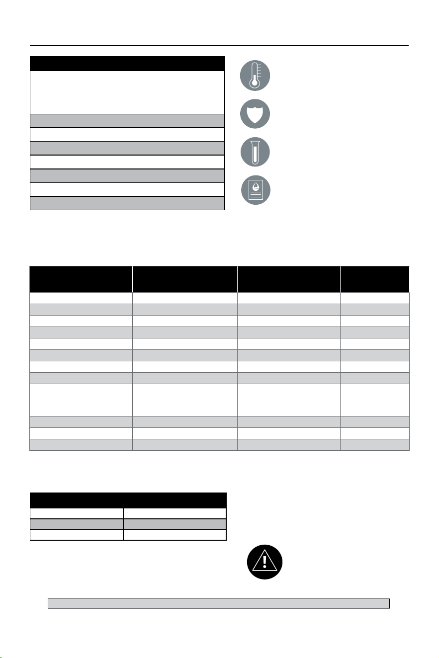
PERFORMANCE DATA
Do not use with water that is micro-
biologically unsafe or of unknown water
quality without adequate disinfection
before or after system.
Filter is only to be used with cold water.
Filter usage must comply with all state and
local laws.
Testing performed under standard laboratory
conditions, actual performance may vary.
Read owner’s manual for general installation
conditions and needs, as well as
manufacturer’s limited warranty.
Contaminant
Inuent Challenge
Concentration (mg/L)
Maximum Permissible
Product Water
Concentration (mg/L)
Average %
Reduction
Arsenic Pentavalent 0.050 ± 10% 0.01 97.80%
Barium 10.0 ± 10% 2.0 98.91%
Cadmium 0.03 ± 10% 0.005 95.41%
Chromium III 0.3 ± 10% 0.1 98.41%
Chromium VI 0.3 ± 10% 0.1 98.60%
Copper 3.0 ± 10% 1. 3 99.02%
Fluoride 8.0 ± 10% 1. 5 95.00%
Lead 0.15 ± 10% 0.005 99.80%
Nitrate/Nitrite (both as N)
Nitrate (as N)
Nitrate (as N)
30.0 ± 10%
27.0 ± 10%
3.0 ± 10%
10.0
10.0
1. 0
Nitrate = 86.1%
Nitrite = 82.4%
Selenium 0.1 ± 10% 0.05 98.90%
TDS 750 ± 40 mg/L 187 92.40%
Turbidity 11 ± 1 NTU 0.5 NTU 97.91%
Reduction & Ratings
Average TDS Reduction 92.40%
Recovery Rating 74.50%
Daily Production 731gpd
System Tested and Certified by WQA to
NSF/ANSI Standard 58 and CSA B483.1 for
the reduction of the claims specified on
the Performance Data Sheet and at www.
WQA.org.
Manufactured by: A. O. Smith Corporation 11270 Park Pl #170 | Milwaukee, WI, 53224 | 1-800-777-1426 | www.aosmith.com
This system conforms to NSF/ANSI 58 for the specific performance claims as verified and substantiated by test data. All contam-
inants reduced by this filter are listed. Not all contaminants listed may be present in your water. Does not remove all contaminants
that may be present in tap water.
This system is acceptable for treatment of influent concentrations
of no more than 27 mg/L nitrate and 3 mg/L nitrite in combination
measured as N and is certified for nitrate/nitrite reduction only for
water supplies with a pressure of 40 psi or greater.
This system has been tested according to NSF/ANSI 58 for reduction
of the substances listed below. The concentration of the indicated
substances in water entering the system was reduced to a concen-
tration less than or equal to the permissible limit for water leaving the
system, as specified in NSF/ANSI 58.
IF-QPRO SPECIFICATIONS
Replacement cartridges:
● Pre-Composite Filter (100372969)
● Post-Composite Filter (
100372968)
● Reverse Osmosis Membrane Cartridge (
100372966)
Overall Dimensions (inches): 17.5L/5.5W/16.9H
Rated service ow: .45gpm
Max capacity: 731gpd
Min working pressure: 40 psi
Max working pressure: 80 psi
Min operating temperature: 39.2 ºF (4 ºC)
Max operating temperature: 100 ºF (38 ºC)

16
CARE AND SAFEGUARDS
RECOVERY RATING:
Recovery rating is the percentage of the inuent water to the membrane portion of the system that is available
to the user as reverse osmosis treated water when the system is operated without a water tank or when the
water tank is bypassed. The system’s recovery rating was veried by testing in accordance with Section 6.8
found in NSF/ ANSI 58.
RECOMMENDED CARE:
This reverse osmosis system contains a replaceable treatment component that is critical for the effective
reduction of total dissolved solids. It is recommended to periodically test this reverse osmosis system to verify it
is performing properly.
This reverse osmosis system contains a replaceable component critical to the efficiency of the system.
Replacement of the reverse osmosis component should be with one of identical specications, as dened by
the manufacturer, to ensure the same efficiency and contaminant reduction performance.
RECOMMENDED SAFEGUARDS:
• Do not install this system where the line pressure may exceed 80 psi. The operating pressure range
for this system is between 40 and 80 psi.
• Install on COLD water lines only.
• It is recommended that your system be installed inside and out of direct sunlight. The system must be
protected from both direct sunlight and freezing temperatures.
• System and installation shall comply with applicable state and local laws.
• Do not operate without the lters installed.
• Do not use with water this is microbiologically unsafe or of unknown water quality without adequate
disinfection before or after the system.
• Nitrate/Nitrite test kit included with the system. See the test kit for sampling instructions.
Recommended to test yearly to ensure system is working properly.
IF-QPRO SPECIFICATIONS
Membrane TDS Reduction: 83.8% minimum
Membrane TDS Reduction: 92.4%+ average
Max TDS: 1,000 ppm
Max Water Hardness @ 6.9 pH = 10 gpg (2.64 gpL)
Max Chlorine in Water: 3 ppm
Supply Water pH Limits: 4-10
Drain (Reject Water) Flow: 2-4x product ow
Supply Water Pressure Limits: 40-80 psi (172-551 kPa)
Supply Water Temperature Limit: 40-100° F (4.4-37° C)
• Because the performance of a reverse osmosis
membrane is highly dependent upon Pressure,
Temperature, and Total Dissolved Solids (TDS),
this data should be used for comparison only.
• Lower temperatures are directly proportional to
a slower ow rate. The reverse osmosis system
should not be installed in a location susceptible to
freezing. Incoming water temperature should not
exceed 100° F (37.7° C).
• The more TDS in the supplier water, the more
lter time required. Incoming TDS should not
exceed 1,000 ppm. Higher water pressure
enables a higher ow rate. Pressure must be
above 40 psi for proper system operation.
• Flow rate and output are determined by three factors:
1. Incoming water temperature
2. Total Dissolved Solids (TDS)
present in supply water
3. Incoming water pressure
REPLACEMENT PARTS
CURRENT PART # DESCRIPTION
100372965 QuadPro SST Tankless RO System
100379239 QuadPro Power Supply
100372970 QuadPro RO E-Faucet
100372971 QuadPro RO Pressure Transducer
100372966 QuadPro RO Membrane
100372968 QuadPro RO Post Filter
100372969 QuadPro RO Pre Filter

17
ARSENIC FACT SHEET
INTRODUCTION:
This system has been tested for the treatment of water containing pentavalent arsenic (also known as As(V),
As(+5), or arsenate) at concentrations of 0.05 mg/L or less. This system reduces pentavalent arsenic but may
not remove other forms of arsenic. This system is to be used on water supplies containing a detectable free
chlorine residual at the system inlet or on water supplies that have been demonstrated to contain only 50 ppb
(0.050 mg/L) pentavalent arsenic. Treatment with chloramine (combined chlorine) is not sufficient to ensure
complete conversion of trivalent arsenic to pentavalent arsenic. Please see the Arsenic Facts section below for
further information.
ARSENIC FACTS:
Arsenic (As) is a naturally occurring contaminant found in many ground waters. Arsenic in water has no color,
taste or odor. It is measured by a laboratory test. Public water utilities must have their water tested for arsenic.
You can get the results from your water utility. If you have your own well, you can have the water tested. The
local health department or the state environmental health agency can provide a list of certied labs. Information
about arsenic in water can be found on the internet at the U.S. Environmental Protection Agency website (epa.
gov/safewater/arsenic).
There are two forms of arsenic: pentavalent arsenic (As(V), As(+5), and arsenate) and trivalent arsenic (also
called As(III), As(+3), and arsenite). Although both forms of arsenic are potentially harmful to human health,
trivalent arsenic is considered more harmful than pentavalent arsenic. In water, arsenic may be pentavalent,
trivalent, or a combination of both. Special sampling procedures are needed for a lab to determine what type
and how much of each type of arsenic is in the water. Check with the labs in your area to see if they can
provide this type of service.
If you get your water from a public water utility, contact the utility to nd out if free chlorine or combined chlorine
is used in the water system. The system is designed to reduce pentavalent arsenic only. It will not convert
trivalent arsenic to pentavalent arsenic. This system was tested in a lab. Under testing conditions, the system
reduced 0.050 mg/L (ppm) pentavalent arsenic to 0.010 mg/L (ppm) (the USEPA standard for drinking water)
or less. The removal performance of pentavalent arsenic of the system may be limited due to water quality
conditions (i.e. iron-containing water or other water quality conditions). Have your treated water tested for
arsenic to check whether the system is working properly.
The QuadPro Membrane must be replaced every 48 months to ensure system will continue to remove
pentavalent arsenic. The component identication is listed in the installation/operation manual.

18
LIMITED WARRANTY
WHAT IS COVERED:
This limited warranty covers defects in materials or workmanship in manufacturing of your InterFlo QuadPro
SST drinking water lter system for the following time periods from date of purchase, except as provided below.
WHAT IS NOT COVERED:
This warranty does not cover lter cartridges and any products that were not installed in compliance with the
instructions or that have been abused or operated incorrectly. The limited warranty stated herein is in lieu of any
and all warranties, express or implied, whether written or oral, including but not limited the implied warranties
of tness for a particular purpose or the implied warranty of merchantability. The manufacturer shall not be
liable for any incidental, consequential, special, punitive, or contingent damages or expenses arising directly
or indirectly from any defect or the use of the system, including but not limited to water damage. Owner shall
be responsible for all labor and any other expenses related to the removal, repair or installation of the ltration
system or any component part. Finally, this warranty is voided if the product is used with parts that are not
genuine manufacturer parts.
This includes, but is not limited to: replacement lters, faucets, and diverter valves.
RETURN POLICY ON DEFECTIVE UNITS:
Any part found defective within the terms of this warranty will be repaired or replaced by the dealer. You pay
only freight from our factory and local dealer charges. To obtain local warranty service, contact original dealer
or an authorized service dealer. If no authorized dealer is located in your area, please ship defective part or
component freight prepaid to A. O. Smith Water Treatment, 1900 Prospect Ct., Appleton, Wisconsin 54914.
A. O. Smith, at its discretion, will repair or replace the part or component at its expense and return part freight
collect.
HOW STATE LAW APPLIES:
Some states do not allow limitations on how long an implied warranty lasts or the exclusion or limitation
of incidental or consequential damages, so the above limitations and exclusion may not apply to you. This
warranty gives you specic legal rights, and you may also have other rights which vary from state to state.
FURTHER EXCLUSIONS AND LIMITATIONS ON WARRANTY:
This warranty is null and void unless the InterFlo QuadPro SST was purchased and installed from an approved
dealer. No dealer, agent, representative, or other person is authorized to extend or expand this limited warranty.
DATE PRE-COMPOSITE POST-COMPOSITE RO
For a period of ONE YEAR The entire reverse osmosis water conditioning unit.
For a period of FIVE YEARS
• Power Supply
• E-Faucet
• Pressure Transducer

19
CARTRIDGE REPLACEMENT CHECKLIST
DATE PRE-COMPOSITE POST-COMPOSITE RO
Keep the following record to track when ltration elements are replaced. Record the date and check the
box in accordance with which elements were replaced.

20
NOTES

21
NOTES

22
NOTES

23
NOTES

A. O. Smith Corporate | 11270 West Park Place, Suite 170
Milwaukee, WI 53224 | www.aosmith.com
100377199 - 2000611123 - RevA1024