
Owner's Manual
20.0 HP
ELECTRIC START
46" MOWER
6 SPEED
GARDEN TRACTOR
Model No.
917.272954
• Safety
• Assembly
• Operation
• Maintenance
• Repair Parts
CAUTION:
Read and follow all Safety
Rules and Instructions before
operating this equipment,
Foranswers toyourquestions
about thisproduct, Call:
1-800-659-5917
Sears Craftsman Help Line
5 am - 5 pm, Mon - Sat
SEARS, ROEBUCKAND CO., HOFFMAN ESTATES, IL 60179
Visit our Craftsmanwebsite:www.sears.com/craftsman
Warranty ............................................... 2
Safety Rules ......................................... 3
Product Specifications .......................... 6
Assembly .............................................. 8
Operation ............................................ 12
Maintenance Schedule ...................... 18
Maintenance ....................................... 18
Service and Adjustments.................... 22
Storage ............................................... 29
Troubleshooting ................................. 30
Repair Parts ........................................ 34
Parts Ordering ..................... Back Cover
LIMITED TWO YEAR WARRANTY ON CRAFTSMAN RIDING EQUIPMENT PARTS
For two (2) years from the dale of purchase, if this Craftsman Riding Equipmentis
maintained, lubricated and tuned up according to the instructionsin the owner's
manual, Sears will repair or replace, free of charge, any parts found to be defective in
material or workmanship. Warranty service is available free of charge by returningyour
Craftsman riding equipment to your nearest Sears Service Center. In-home warranty
service is available but a trip charge will apply. This warranty applies only while this
productis in the United States.
This Warranty does not cover:
• Expendable items which become worn during normal use, such as blades, spark
plugs, air cleaners, belts and oil filters.
• Tire replacement or repair caused by punctures from outside objects, suchas nails,
thorns, stumps, or glass.
• Repairs necessary because of operator abuse, including but not limitedto, damage
caused by towing objects beyond the capabilLtyof the riding equipment, impacting
objects that bend the frame or crankshaft, or over speeding the engine.
• Repairs necessary because of operator negligence, including but not limited to,
electrical end mechanical damage caused by improper storage, failure to use the
proper grade and amount of engine oil, failure to keep the deck clear offlammable
debris, or the failure to maintain the equipment according to the instructionscon-
tained in the owner's manual.
• Engine (fuel system) cleaning or repairs caused by fuel determined to be contami-
nated or oxidized (stale). In general, fuel should be used withinthirty (30) days of its
purchase date.
• Riding equipment used for commercial or rental purposes. A product is "used for
commercial purpose" if is used for any purpose other than single family household
dwellings or in usage where profit is made.
LIMITED 90 DAYWARRANTY ON BATTERY
For ninety (90) days from date of purchase, if any battery included with this riding
equipment proves detective in material or workmanship and our testing determines the
battery will not hold a charge, Sears will replace the battery at no charge. Warranty
service is available free of charge by returning your Craftsman riding equipment to
your nearest Sears Service Center. In-home warranty service is available but a trip
charge will apply. This warranty applies only while this product is in the United States.
TO LOCATE THE NEAREST SEARS SERVICE CENTER OR TO SCHEDULE IN-HOME
WARRANTY SERVICE, SIMPLY CONTACT SEARS AT 1-600-4-MY-HOME
This Warranty gives you specific legal rights, and you may also have other rights which
may vary from state to state.
Sears, Roebuck end Co., D/817 WA, Heflman Estates, IL 60179
IMPORTANT:Thiscuttingmachineiscapableofamputatinghandsandfeetand
throwing objects. Failure to observe the following safety instructionscould result in
serious injuryor death.
I. GENERAL OPERATION
• Read, understand,and followall
instructionsin the manual and on the
machinebefore starting.
• Only allow responsibleadults,who are
familiarwiththe instructions,to operate
the machine.
• Clear the area of objectssuchas rocks,
toys,wire, etc., which couldbe picked
upand thrown by the blade.
• Be sure the area is clear ofother people
beforemowing. Stop machine if anyone
entersthe area.
• Never carry passengers.
• Do not mow in reverse unless absolutely
necessary. Always look downand
behind before and while backing.
• Be aware of the mowerdischarge
directionand do not point it at anyone.
Do not operate the mower without either
the entiregrass catcher or the guard in
place.
• Slowdown before tuming.
• Never leave a runningmachine
unattended. A;waysturn off blades, set
parkingbrake, stop engine, and remove
keys before dismounting.
Turn off blades when not mowing.
Stop engine before removinggrass
catcher or uncloggingchute.
Mow only in daylightor good artificial
light.
Do not operate the machine while under
the influenceof alcohol or drugs.
Watch fortrafficwhen operating near or
crossing roadways.
Use extra cars when loading or unload-
ingthe machine intoa trailer or truck.
Data indicatesthat operators,age 60
years and above, are involvedin a large
percentage of dding mower-related
injudas. These operatorsshould
evaluate their ability to operate the dding
mower safely enoughto protectthem-
selvesand othersfrom seriousinjury.
• Keep machine free of grass, leaves or
other debdsbuild-up which can touch
hotexhaust/ engineparts and bum. Do
notallowthe mower deck to plow leaves
or other debds whichcan cause build-
upto occur.Clean any ait or fuel
spillage before operating or stonngthe
machine. Allow machine to coolbefore
storage. 3
II. SLOPE OPERATION
Slopes are e major factor relatedtoloss-of-
controland tipover accidents,whichcan re-
sult in severe injury or death. All slopes
require extra caution. Ifyou cannotback up
the slope or if you feel uneasy on it, do not
mow it.
DO:
• Mow up and down slopes,not across.
• Remove obstacles such as rocks,tree
limbs,etc.
Watch for holes, ruts,or bumps. Uneven
terrain couldoverturnthe machine. Taft
grass can hide obstacles.
Use slowspeed. Choose a low gear so
thatyou will nothave to stopor shift
while on the slope.
Follow the manufacturer's recommenda-
tionsfor wheel weights or counter-
weightsto improvestability.
Use extra care withgrass catchers or
other attachments. These can change
the stabilityof the machine.
Keep all movement on the slopes slow
and gradual. Do notmake sudden
changes in speed or direction.
Avoid startingor stoppingon a slops. If
tires lose traction, disengagethe blades
and proceed slowlystraightdown the
slope.
DO NOT:
• Do not turnon slopes unless necessary,
and then, turnslowly and gradually
downhill, if possible.
• Do not mow near drep-offs,ditches, or
embankmentS. The mower could
suddenly turnover ifa wheel isover the
edge ofa cliffor ditch,or ifan edge
caves in.
• Do not mow onwet grass. Reduced
traction could cause sliding.
• Do not try tostabilizethe machineby
puttingyourfnot on the ground.
• Do not usa grass catcher on steep
slopes.
Ill.CHILDREN
Tragicaccidentscanoccurif the operator
is not alerttothe presence of children.
Children are often attracted to the
machine and the mowing activity. Never
assume that children will remain where
you last saw them.
• Keep children out of the mowing area
and under the watchful care of another
responsible adult.
• Be alert and turn machine off ifchitdren
enter the area.
• Before and when backing, look behind
and down for small children.
• Never carry children. They may fall off
and be seriously injured or interfere
with safe machine operation.
• Never allow children to operate the
machine.
• Use extra care when approaching blind
comers, shrubs, trees, or other objects
that may obscure vision.
IV. SERVICE
• Use extra care in handling gasoline
and other fuels. They are flammable
and vapors are explosive.
-Use only an approved container.
- Never remove gas cap or add fuel
with the engine running. Allow
engine to cool before refueling. Do
notsmoke.
-Never refuel the machine indoors.
- Never store the machine or fuel
container inside where there is an
open flame, such as a water heater.
• Never run a machine inside a closed
area.
• Keep nuts and bolts, especially blade
attachment bolts, tight and keep
equipment in good condition.
• Never tamper with safety devices.
Check their proper operation regularly.
• Keep machine free of grass, leaves, or
other debris build-up. Clean oil or fuel
spillage. Allow machine to cool before
storing.
• Stop and inspect the equipment if you
strike an object. Repair, if necessary,
before restarting.
• Never make adjustments or repairs
with the engine running.
• Grass catcher components are subject
to wear, damage, and deterioration,
which could expose moving parts or
allow objects to be thrown. Frequently
check components and replace with
manufacturer's recommended parts,
when necessary.
• Mower blades are sharp and can cut.
Wrap the blade(s) or wear gloves, and
use extra cautionwhen servicing them.
• Check brake operation frequently.
Adjust and service as required.
• Be sure the area is clear ofother
people before mowing. Stop machine if
anyone enters the area.
• Never carry passengers or children
even with the blades off.
• Do not mow in reverse unless abso-
lutely necessary. Always look down
and behind before and while backing.
• Never carry children. They may fall off
and be seriously injured or intedere
with safe machine operation.
• Keep children out of the mowing area
and under the watchful care of another
responsible adult.
• Be alert and turn machine off if children
enter the area.
• Before and when backing, look behind
and down for small children.
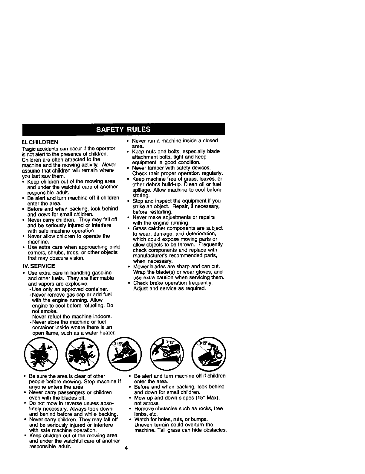
• Mow up and down slopes (15° Max),
notacross.
• Remove obstacles such as rocks, tree
limbs,etc.
• Watch for holes, ruts, or bumps.
Uneven terrain could overturn the
machine. Tall grass can hide obstacles.
4
• Use slow speed. Choose a low gear so
that you will not have to stop or shift
while on the siope.
• Avoid starting or stoppingon a slope. If
tires lose traction, disengage the
blades and proceed slowly straight
down the slope.
• If machine stops while going uphill,
disengage blades, shift into reverse
and back clownslowly.
• Do not turn on slopes unless neces-
sary, and then, turn slowlyand gradu-
ally downhill, if possible.
_,Look for this symbol to point out
importantsafety precautions. It means
CAUTION!!! BECOMEALERT!!I YOUR
SAFETY IS iNVOLVED.
/I, CAUTION: In order to prevent
accidental starting when setting up,
transporting, adjusting or making repairs,
always disconnect spark plug wire and
place wire where it cannot contact spark
plug.
_CAUTION: Do not coast down a hill in
neutral, you may lose control ofthe
tractor.
/I, CAUTION: Tow onlythe attachments
that are recommended by and comply
with specifications of the manufacturer of
your tractor. Use common sense when
towing. Operate only at the lowest
possible speed when on a slope. Too
heavy of a load, while on a slope, is
dangerous. "Sras can lose traction with
the ground and cause you to lose control
ofyour tractor.
_WARNING: Engine exhaust, some of
its constituents, and certain vehicle
components contain or emit chemicals
known to the State of California tocause
cancer and birth defects or other repro-
ductive harm.
/I, WARNING: Batteryposts, terminals
and related accessories contain lead and
lead compounds, chemicals known to the
State of California to cause cancer and
birth defects or other reproductiveharm.
Wash hands after handling.
5
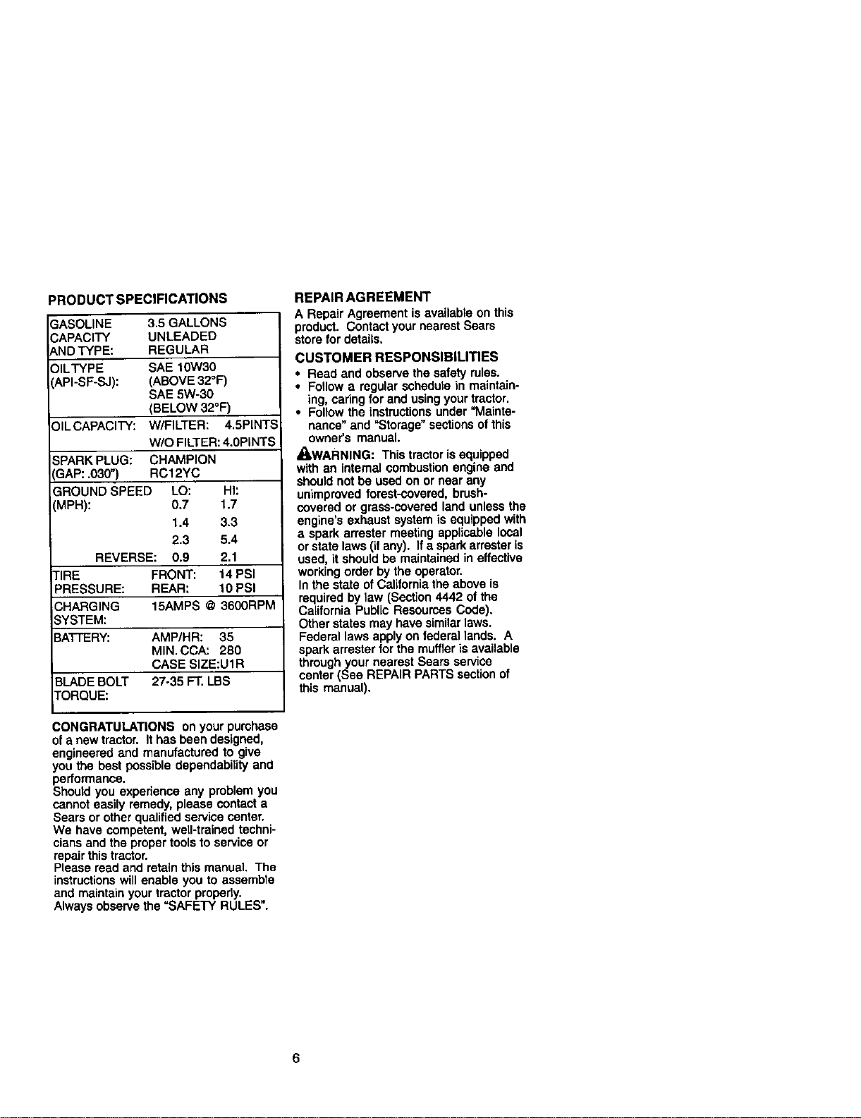
PRODUCT SPECIFICATIONS
GASOLINE 3.5 GALLONS
CAPACITY UNLEADED
ANDTYPE: REGULAR
OILTYPE SAE 10W30
_.PI-SP-SJ): (ABOVE 32°F)
SAE 5W-30
(BELOW 32°F)
ILCAPACITY: W/FILTER: 4.5PINTS
W/O FILTER: 4.0PINTS
SPARK PLUG: CHAMPION
_AP: .030") RC12YC
GROUND SPEED LO: Hh
(MPH): 0.7 1.7
1.4 3.3
2.3 5.4
REVERSE: 0.9 2.1
TIRE FRONT: 14 PSI
PRESSURE: REAR: 10 PSI
CHARGING 15AMPS @ 3600RPM
SYSTEM:
BATTERY: AMP/HR: 35
MIN. CCA: 280
CASE SIZE:U1 R
BLADE BOLT 27-35 FT. LBS
TORQUE:
REPAIR AGREEMENT
A Repair Agreement is available on this
product. Contact your nearest Sears
store for details,
CUSTOMER RESPONSIBILITIES
• Read and observe the safety rules.
• Follow a regular schedule in maintain-
ing, caring for and using your tractor.
• Follow the instructions under "Mainte-
nance" and "Storage" sections of this
owner's manual.
/I=WARNING: This tractor is equipped
with an internal combustion engine and
should not be used on or near any
unimproved forest-covered, brush-
covered or grass-covered land unless the
engine's exhaust system is equipped with
a spark arrester meeting appUcable local
or state laws (ifany). If a spark arrester is
used, it should be maintained in effective
working order by the operator.
In the state of California the above is
required by taw (Section 4442 ot the
California Public Resources Cede).
Other states may have similar laws.
Federal laws apply on federal lands. A
spark arrester for the muffler is available
through your nearest Sears service
center (See REPAIR PARTS section of
this manual).
CONGRATULATIONS on your purchase
ofa new tractor. It has been designed,
engineered and manufactured to give
you the best possible depandability and
performance.
Should you experience any problem you
cannot easily remedy, please contact a
Sears or other qualified service center.
We have competent, well-trained techni-
cians and the proper tools to service or
repair thistractor.
Please read and retain this manual. The
instructions will enable you to assambte
and maintain your tractor proporiy.
Always observe the =SAFETY RULES".
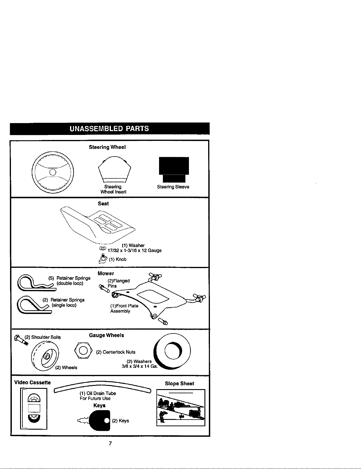
Steering Wheel
Steering
Wheel Insert
Steenng Sleeve
Seat
(1) Washer
17/32 x 1-3/16 x 12 Gauge
_(1) Knob
(5) etainer Spnngs
(double loop)
(2) etainer Spr;ngs
(single loop)
Mower
(2)Ranged _
(1)Front Plate "_ =
Assembly _(_
-%
) Shoulder Bolts Gauge Wheels
y)/ _ (.,wes,.,.,.'_._ /
(2) Wheels 3/8 x 3/4 x 14 Ga_m,f /
Video Casseffe
7--
For Future Use
Keys
(2) Keys
Slope Sheet
I
7
Your new tractor has been assembled at the factorywith exception of those parts left
unassembled for shipping purposes• To ensure safe and proper operation of your
tractor all parts and hardware you assemble must be tightened securely, Use the
correct tools as necessary to insure proper tightness.
TOOLS REQUIRED FOR ASSEMBLY
A socket wrench set will make assembly
easier. Standard wrench sizes you need
are listed below.
(1) 9/16" wrench (1) Pliers
(1) 1/2"wrench (1) Utility knife
(1) 3/4" socket with
drive ratchet
(1) "Sre pressure gauge
When right or left hand is mentioned in
this manual, it means, from your pointof
view, when you are in the operating
position (seated behind the steering
wheel).
TO REMOVE TRACTOR FROM
CARTON
UNPACK CARTON
1, Remove all accessible loose parts and
parts cartons from carton.
2. Cut, fromtop to bottom, along lines on
all four corners of carton, andlay
panels flat.
3. Remove mower and packing materi-
als.
4. Check for any additional loose parts or
cartons and remove.
BEFORE REMOVING TRACTOR
FROM SKID
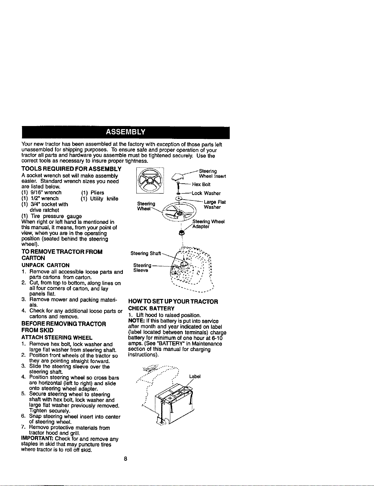
ATTACH STEERING WHEEL
1. Remove hex bolt, lock washer and
large flat washer from steedng shaft.
2. Positionfront wheels ofthe tractor so
they are pointingstraight forward.
3. S)ide the steering sleeve over the
steering shaft.
4. Position steering wheel so cross bars
are horizontal (left to right) and slide
or_tosteering wheel adapter.
5. Secure steering wheel to steering
shaft with hex bolt, lock washer and
large fiat washer previously removed.
"13ghtensecurely.
6. Snap steering wheel insert into center
of steering wheel.
7. Remove protective materials from
tractor hood and grill.
IMPORTANT: Check for and remove any
staples in skid that may puncture tires
where tractor is to roll offskid.
(_ _ _Steedng
_Wheel Insert
_--- HsxBolt
&_-----Lock Washer
n _ LargeFlat
Wheel
• el
t
SteenngShaft-._._- _'_._._...-_.'_"-
Steenng_ ._-. ,',
Seeve ...-' -, , ',,
/ f sI i_
HOW TO SET UP YOUR TRACTOR
CHECK BA'FI'ERY
1. Lift hood to raised position.
NOTE: It thisbattery isput intoservice
after month and year indicated on label
(label located between terminals) charge
battery for minimum ofone hourat 6-10
ampe. (See "BATTERY"in Maintenance
section of this manual for charging
instructions),
,....F,, ÷_-._.
Label
." .,
8
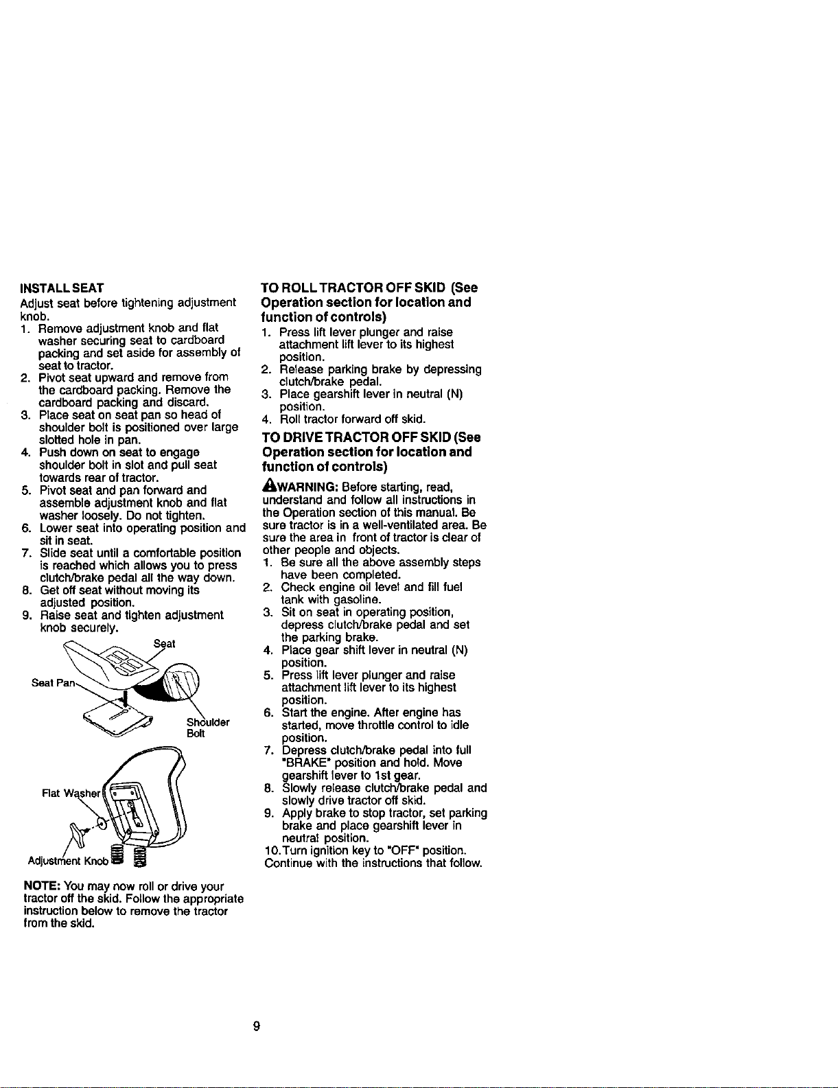
INSTALL SEAT
Adjust seat before tightening adjustment
knob.
1. Remove adjustment knob and flat
washer securing seat to cardboard
packing and set aside for assembly of
seat to tractor.
2. Pivot seat upward and remove from
the cardboard packing. Remove the
cardboard packing and discard.
3. Place seat on seat pan so head of
shoulder bolt is positioned over large
slotted hole in pan.
4. Push down on seat to engage
shoulder bolt in slot and pull seat
towards rear of tractor.
5. Pivot seat and pan forward and
assemble adjustment knob and flat
washer loosely. Do not tighten.
6. Lower seat into operating position and
sit in seat.
7. Slide seat until a comfortable position
is reached which allows you to press
clutch_rake pedal all the way down.
8. Get off seat without moving its
adjusted position.
9. Raise seat and tighten adjustment
knob securely.
Seat
NOTE: You may now rollor drive your
tractor off the skid. Follow the appropriate
instructionbelow to remove the tractor
from the skid.
TO ROLL TRACTOR OFF SKID (See
Operation section for location and
function of controls)
1. Press lift lever plunger and raise
attachment lift lever to its highest
position.
2. Release parking brake by depressing
clutch/brake pedal,
3. Place gearshift lever in neutral (N)
position.
4, Roll tractorforward off skid.
TO DRIVE TRACTOR OFF SKID (See
Operation section for location and
function of controls)
/I, WARNING: Before starting, read,
understand and follow all instructionsin
the Operation section ofthis manual. Be
sure tractor is in a well-ventilated area. Be
sure the area in front of tractor isclear of
other people and objects.
1. Be sure all the above assembly steps
have been completed.
2. Check engine oil level and fill fuel
tank with gasoline.
3. Sit on seat in operating position,
depress clutch/brake pedal and set
the parking brake.
4, Place gear shift lever in neutral (N)
position.
5. Press lift lever plunger and raise
attachment lift lever to its highest
position.
6. Start the engine. After engine has
started, move throttlecontrol to idle
position.
7. Depress clutch/brake pedal into full
"BRAKE" position and hold. Move
gearshift lever to 1stgear.
8. Slowly release clutch/brake pedal and
slowlydrive tractor offskid,
9, Apply brake to stop tractor,set parking
brake and place gearshift lever in
neutral position.
10.Turn ignitionkey to "OFF" position.
Continue with the instructions that follow.
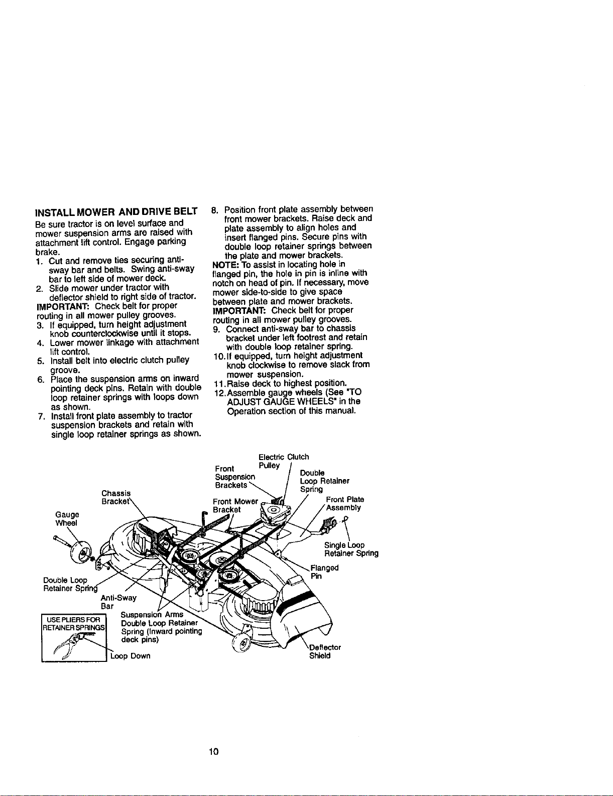
INSTALLMOWERANDDRIVEBELT
Besuretractoris on level surface and
mower suspension arms are raised with
attachment liftcontrol. Engage parking
brake.
1. Cut and remove ties securing anti-
sway bar and belts. Swing anti-sway
bar to left side of mower deck.
2. Slide mower under tractor with
deflector shield to right side of tractor.
IMPORTANT: Check belt for proper
routingin all mower pulley grooves.
3. If equipped, turn height adjustment
knob counterclockwise until it stops.
4. Lower mower linkage with attachment
lift control.
5. Install belt into electric clutch puney
groove.
6. Piece the suspension arms on inward
pointingdeck pins. Retain with double
loop retainer springs with loops down
as shown.
7. Install frontplate assembly to tractor
suspension brackets and retain with
single loop retainer springs as shown.
Chassis
Gauge
Wheel
8, Positionfront plate assembly between
front mower brackets. Raise deck and
plate assembly to align holes and
insed flanged pins. Secure pins with
double loop retainer springs between
the plate and mower brackets.
NOTE: To assistin locatinghole in
flanged pin, the hole in pin is inline with
notchon head ofpin. If necessary, move
mower side-to-side to give space
between plate and mower brackets.
IMPORTANT: Check belt for proper
routingin all mower pulley grooves.
9. Connect anti-sway bar to chassis
bracket under left footrest and retain
with double loop retainer spring.
lO.If equipped, turn height adjustment
knob clockwise to remove slack from
mower suspension.
11. Raise deck to highest position.
12,Assemble gauge wheels (See "TO
ADJUST GAUGE WHEELS" in the
Operation section of this manual.
ElectncClutch
Front Pulley
Suspension Double
Brackets_ LoopRetainer
Spring
FrontMower FrontPlate
Bracket
Double Loop
Retainer Spdng
Anti-Sway
Bar
USEPLIERSFOR "ne_
Double Loop Ret_
RETAIN._.__.._eNGS_=:__D=:_= Spring (Inward pointing
__ deck pins)
• "JJ I Loop Down
Single Loop
Retainer Spring
ector
Shield
10
CHECK TIRE PRESSURE
The tireson your tractorwere overinflated
at the factoryfor shippingpurposes.
Correcttire pressureis importantforbest
cuttingperformance.
• Reduce tire pressureto PSi shown in
"PRODUCT SPECIFICATIONS" section
ofthis manual.
CHECK MOWER LEVELNESS
For bestcuttingresults, mower should be
properlyleveled. See "TO LEVEL MOWER
HOUSING" inthe Service and Adjustments
sectionofthis manual.
CHECK FOR PROPER POSITION OF ALL
BELTS
See the figuresthat are shown for replac-
ing motion,mower drive, and mower blade
drivebelts in the Serviceand Adjustments
sectionofthis manual. Verifythatthe belts
are muted correctly.
CHECK BRAKE SYSTEM
Afteryou learn how tooperate your tractor,
checkto see thatthe brake is properly
adjusted. See "TO ADJUST BRAKE" inthe
Service and Adjustmentssection ofthis
manual.
V'CHECKLIST
Before you operate and enjoy your new
tractor,we wish to assure that you
receive the best performance and
satisfactionfrom this quality product.
Please review the following checklist:
,/All assembly instructionshave been
completed.
`/No remaining loose parts in carton.
`/Battery is properly prepared and
charged.(Minimum 1 hour at 6 amps).
,/Seat is adjusted comfortably and
tightened securely.
/ All tires are properly inflated. (For
shipping purposes, the tires were
overinflated at the factory).
/ Be sure mower deck is properly
leveled side-to-side/front-to-rear for
best cuttingresuRs. (Tires must be
properly inflated for leveling).
,/Check mower and drive belts. Be
sure they are routed property around
pulleys and inside all belt keepers.
,/Check wiring. See that all connec-
tions are stillsecure and wires are
properly clamped.
While learning how to use your tractor,
pay extra attention to the following
important items:
,/Engine oil is at proper level.
,/Fuel tank is filled with fresh, clean,
regular unleaded gasoline.
`/Become familiarwith all controls-
their tocation and function. Operate
them before you start the engine.
,/Be sure brake system is in safe
operating condition.
11
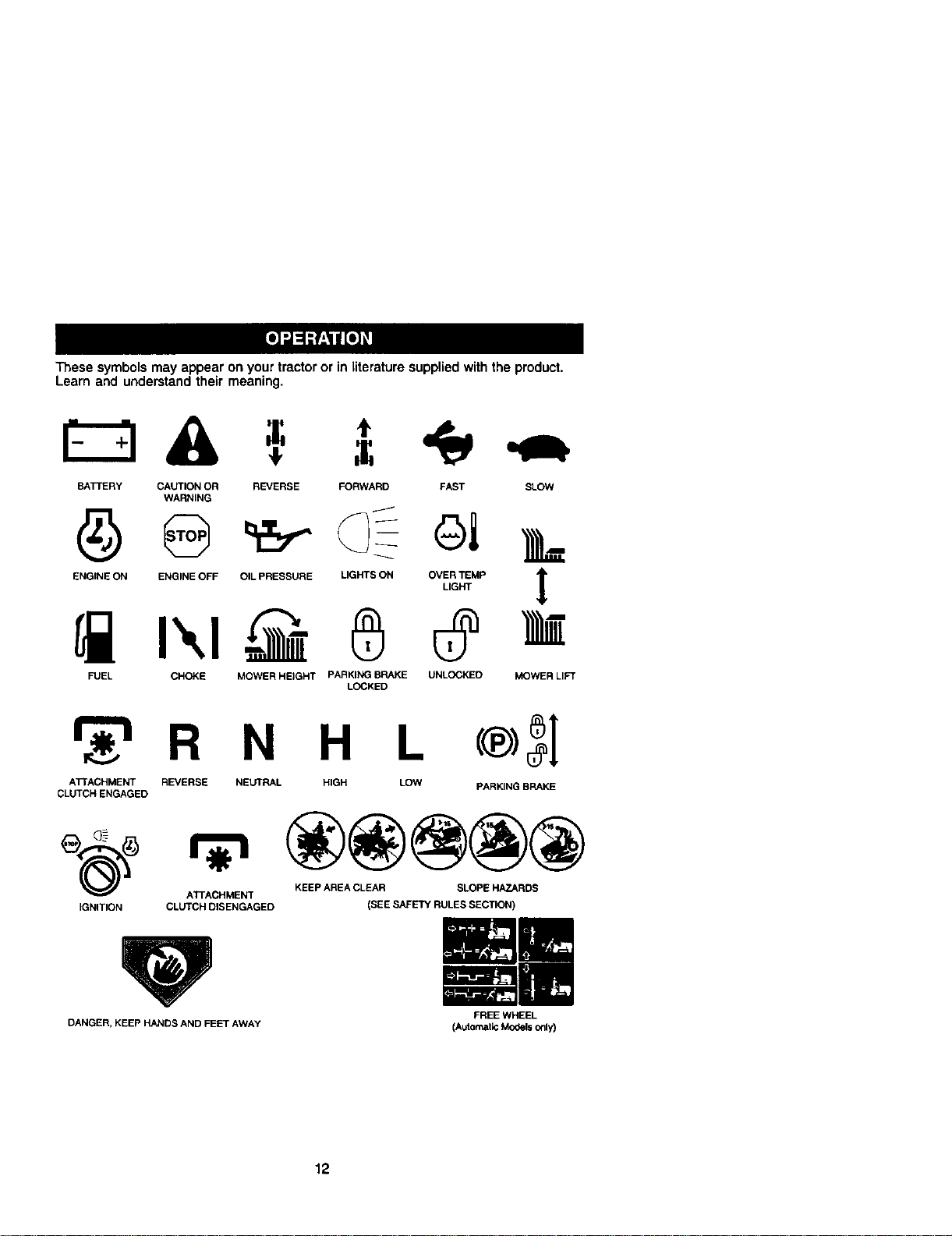
These symbols may appear on your tractor or in literature supplied with the product.
Learn and understand their meaning.
BATTERY CAUTION OR REVERSE FORWARD FAST SLOW
WARNING
ENOINEONENG,NEOFEO,LPRESSOREL,e._SONO%_MP ]_
FUEL CHOKE MOWER HEIGHT PARKING BRAKE UNLOCKED MOWER LIFT
LOCKED
_r_'l R N H L
ATTACHMENT REVERSE NEUTRAL HIGH LOW
CLUTCH ENGAGED
®3I
PARKING BRAKE
ATTACHMENT KEEP AREA CLEAR SLOPE HAZARDS
IGNITION CLUTCH DISENGAGED
DANGER, KEEP HANDS AND FEET AWAY
(SEE SAFETY RULES SECTION)
FREE WHEEL
(Automatk: MOdels only)
12
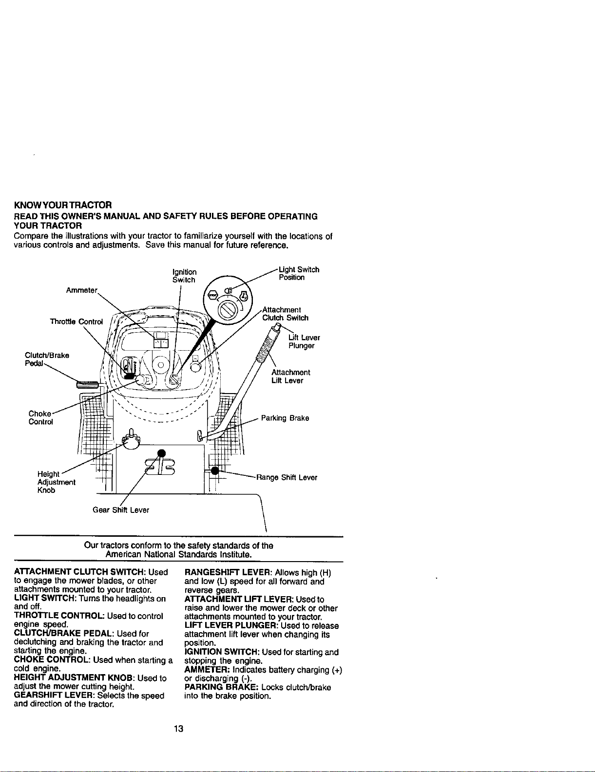
KNOW YOUR TRACTOR
READ THIS OWNER'S MANUAL AND SAFETY RULES BEFORE OPERATING
YOUR TRACTOR
Compare the illustrations with your tractor to familiarize yourself with the locations of
variouscontrolsand adjustments, Save this manual for future reference.
Ammeter,
Ignition
Switch Position
Throttle Control
Switch
ClutcWBrake
Plunger
A_achment
Lift Lever
Control
Parking Brake
Height
Adjustment
Knob
ShiffLever
Gear Shift Lever
\
Our tractors conform tothe safety standards of the
American National Standards Institute.
A'I'FACHMENT CLUTCH SWITCH: Used
to engage the mower blades, or other
attachments mountedto your tractor.
LIGHT SWITCH: Turns the headlightson
and off.
THROTTLE CONTROL: Used to control
engine speed.
CLUTCH/BRAKE PEDAL: Used for
declutching and braking the tractor and
starting the engine.
CHOKE CONTROL: Used when starting a
cold engine.
HEIGHT ADJUSTMENT KNOB: Used to
adjust the mower cutting height.
GEARSHIFT LEVER: Selects the speed
and direction ofthe tractor.
RANGESHIFT LEVER: Allows high (H)
and low (L) speed for all forward and
reverse gears.
AI-rACHMENT LIFT LEVER: Used to
raise and lower the mower deck or other
attachments mounted to your tractor,
LIFT LEVER PLUNGER: Usedto release
attachment liftlever when changing its
position.
IGNITION SWITCH: Used for starlingand
stopping the engine.
AMMETER: Indicates batterycharging (+)
or discharging (-).
PARKING BRAKE: Locks clutch/brake
intothe brake position.
13
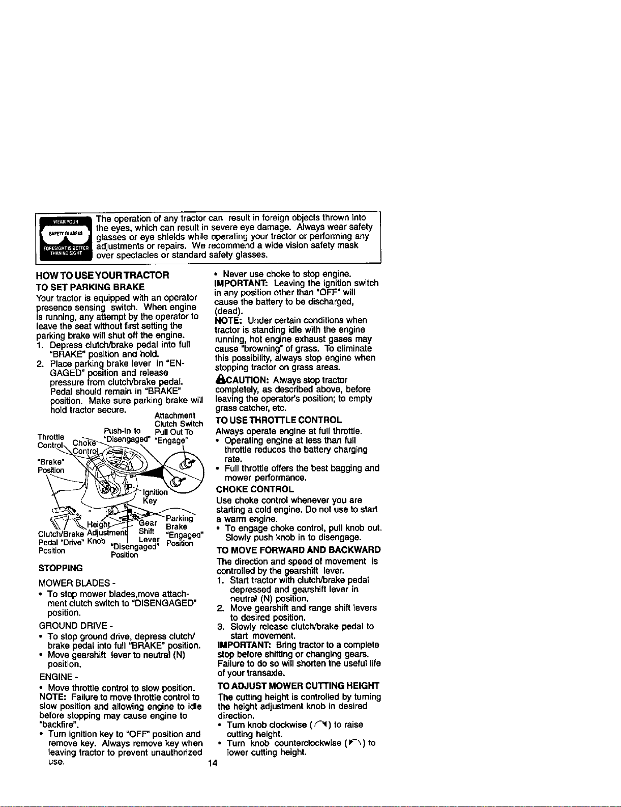
The operation ofany tractor can result in foreign objects thrown into
the eyes, which can result in severe eye damage. Always wear safety
glasses or eye shields while operating your tractor or performing any
adjustments or repairs. We recommend a wide vision safety mask
over spectacles or standard safety glasses.
HOW TO USE YOUR TRACTOR
TO SET PARKING BRAKE
Your tractor is equipped with an operator
presence sensing switch. When engine
is running,any attempt by the operatorto
leave the seat withoutfirstsetting the
parkingbrake will shut offthe engine.
1. Depress clutch/brake pedal into full
"BRAKE" position and hold.
2. Place parking brake lever in "EN-
GAGED" position and release
pressure from clutch/brake pedal.
Pedal should remain in "BRAKE"
position. Make sure parking brake will
hold tractor secure.
Attachment
Clutch Switch
Push-Into PullOutTo
Thro_le Chok_e_Disengaged• "Engage"
°n'r_-_\Control_
Position "_'_'_"-
_ng
• Brake
- ... Disengaged
_'osKion position
STOPPING
MOWER BLADES -
• To stop mower blades,move attach-
ment clutchswitch to "DISENGAGED"
position.
GROUND DRIVE -
• To stop ground drive, depress clutch/
brake pedal into full "BRAKE" position.
• Move gearshift lever to neutral (N)
position.
ENGINE -
• Move throttle controlto slow position.
NOTE: Failure to move throttle control to
slow position and allowing engine to idle
before stopping may cause engine to
"backfire".
• Turn ignition key to "OFF" position and
remove key. Always remove key when
leaving tractor to prevent unauthorized
use,
• Never use choke to stop engine.
IMPORTANT: Leaving the ignition switch
in any position other than "OFF" will
cause the battery to be discharged,
(dead).
NOTE: Under certain conditionswhen
tractor is standing idle with the engine
running, hot engine exhaust gases may
cause "browning" of grass. To eliminate
this possibility,always stop engine when
stoppingtractor on grass areas.
_-CAUTION: Always stoptractor
completely, as described above, before
leavingthe operator's position;to empty
grass catcher,etc.
TO USE THRO'n'LE CONTROL
Always operate engine at full throttle.
• Operating engine at less than full
throttle reduces the battery charging
rate.
• Full throttleoffers the best bagging and
mower performance.
CHOKE CONTROL
Use choke controlwhenever you are
starting a cold engine. Do not use to start
a warm engine.
• To engage choke control, pull knob out.
Slowly push knob in to disengage.
TO MOVE FORWARD AND BACKWARD
The direction and speed of movement is
controlled by the gearshift lever.
1. Start tractor with clutch/brake pedal
depressed and gearshift lever in
neutral (N) position.
2. Move gearshift and range shift levers
to desired position.
3. Slowly release clutch/brake pedal to
start movement.
IMPORTANT: Bring tractor to a complete
stop before shiftingor changing gears.
Failure to do so will shorten the useful life
of your transaxle.
TO ADJUST MOWER CUTTING HEIGHT
The cutting height is controlled by turning
the height adjustment knob in desired
direction.
• Turn knob clockwise (_ ) to raise
cutting height.
• Turn knob counterclockwise (_-_)to
lower cutting height.
14
Thecuttingheight range is approximately
1-1/2" to 4-1/2". The heights are mea-
sured from the ground to the blade tip with
the engine not running. These heights are
approximate and may vary depending
upon soil conditions, height of grass and
types of grass being mowed.
• The average lawn should be cut to
approximately 2-1/2 inches during the
cool season and to over 3 inches
during hot months. For healthier and
better locking lawns, mow often and
after moderate growth.
• For best cuttingperformance, grass
over 6 inches in height should be
mowed twice. Make the firstcut
relatively high; the second to desired
height.
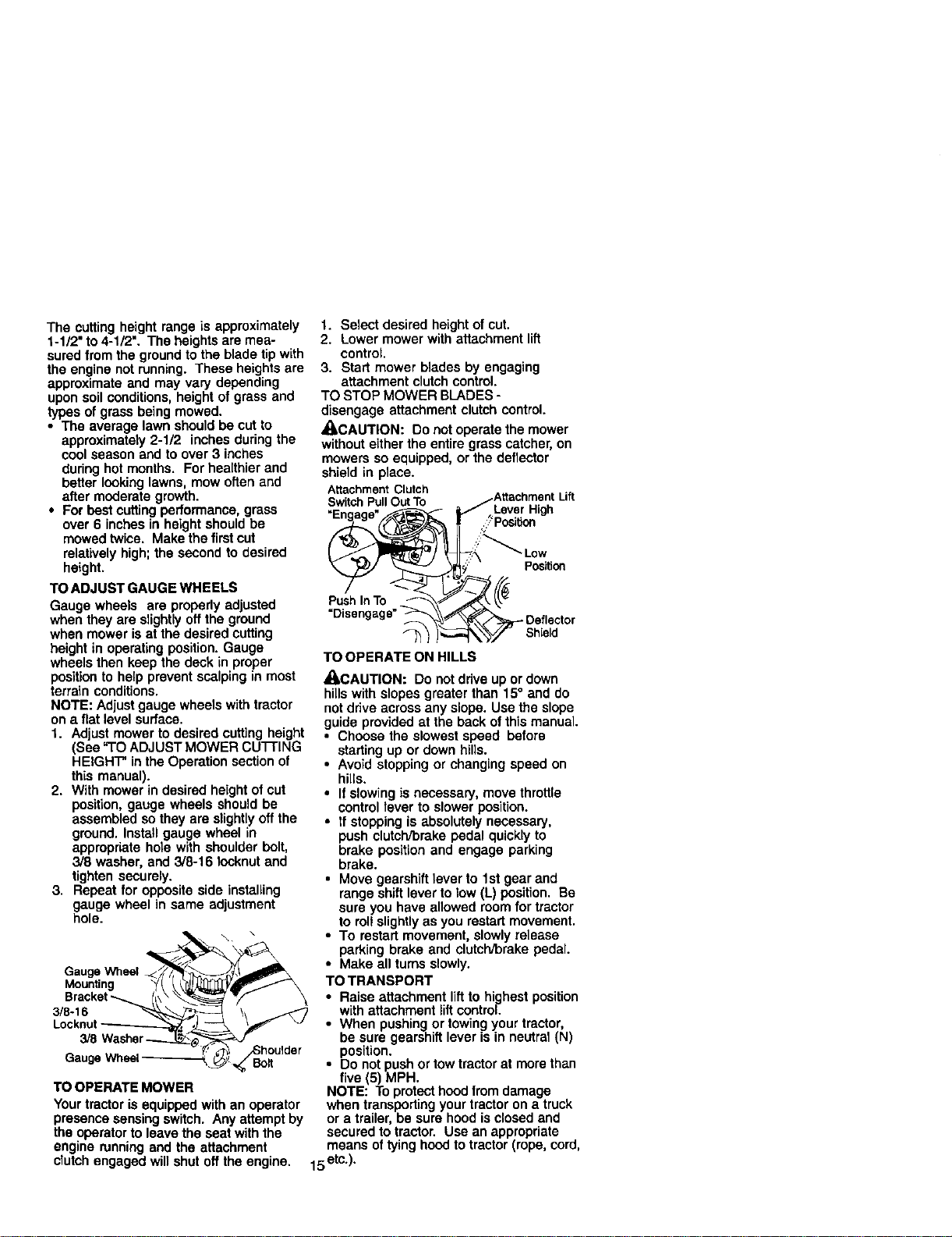
TO ADJUST GAUGE WHEELS
Gauge wheels are properly adjusted
when they are slightlyoff the ground
when mower is at the desired cutting
height in operating position. Gauge
wheels then keep the deck in proper
position to help prevent scalping in most
terrain conditions.
NOTE: Adjust gauge wheels with tractor
on a flat level surface.
1. Adjust mower to desired cutting height
(See "TO ADJUST MOWER CU'I-FING
HEIGHT" in the Operation section of
this manual).
2. With mower in desired height of cut
position, gauge wheels should be
assembled so they are slightlyoff the
ground. Install gauge wheel in
appropriate hole with shoulder bolt,
3/8 washer, and 3/8-16 Iocknut and
tighten securely.
3. Repeat for opposite side installing
gauge wheel in same adjustment
hole.
\ \
Oau0eW. ,
Mounting _(/ /__
Bracket_ I_\\ _ "w/_ \
3/8 Washer_'_----._,_ _ ..
" houlder
eug.Wh.,
TO OPERATE MOWER
Your tractor is equippedwith an operator
presence sensing switch. Any attempt by
the operator to leave the seat with the
engine runningand the attachment
clutch engaged will shut off the engine.
1. Select desired height of cut.
2. Lower mower with attachment lift
control.
3. Start mower blades by engaging
attachment clutch control.
TO STOP MOWER BLADES -
disengage attachment clutch control.
_LCAUTION: Do not operate the mower
without either the entire grass catcher, on
mowers so equipped, or the deflector
shield in place.
Attachment Clutch
SwitchPull OutTo
Lever High
Position
Push In TO
- Deflector
_--_ Shield
TO OPERATE ON HILLS
_I_CAUTION: Do not drive up or down
hillswith slopes greater than 15° and do
notdrive across any slope. Use the slope
guide provided at the back of this manual.
• Choose the slowest speed before
starting up or down hills.
• Avoid stopping or changing speed on
hills.
• If slowing is necessary, move throttle
control lever to slower position.
• tf stopping is absolutely necessary,
push clutch/brake pedal quickly to
brake position and engage parking
brake.
• Move gearshift lever to 1st gear and
range shift lever to low (L) position. Be
sure you have allowed room for tractor
to roll slightly as you restart movement.
• To restart movement, slowly release
parking brake and clutch/brake pedal.
• Make all turns slowly.
TO TRANSPORT
• Raise attachment liftto highest position
with attachment liftcontrol.
• When pushing or towing your tractor,
be sure gearshift lever is in neutral (N)
position.
• Do not push or tow tractor at more than
five (5) MPH.
NOTE: To protect hoodfrom damage
when transporting your tractor on a truck
or a trailer, be sure hood is closed and
secured to tractor. Use an appropriate
means of tying hoodto tractor (rope, cord,
15etc.).
TOWINGCARTSANDOTHERATtACH-
MENTS
Towonlytheattachmentsthatare
recommendedbyandcomplywith
specificationsofthemanufacturerofyour
tractor.Usecommonsensewhentowing.
Tooheavyofa load, while on a slope, is
dangerous. _res can lose traction with
the ground and cause you to lose control
ofyour tractor.
BEFORE STARTING THE ENGINE
CHECK ENGINE OIL LEVEL
The engine in yourtractor has been
shipped, from the factory, already filled
with summer weight oil.
1. Check engine oilwith tractor on level
ground.
2. Unthread and remove oil fill cap/
dipstick;wipe oil off. Reinsert the
dipstickintothe tube and rest oil fill
cap on the tube. Do not thread the
cap onto the tube. Remove and read
oil level. If necessary, add oil untit
"FULL" mark on dipstick is roached.
Do not overfill.
• For cold weather operation you should
change oilfor easier starting (See '_OIL
VISCOSITY CHART" in the Mainte-
nance section ofthis manual).
• To change engine oil,see the Mainte-
nance section in this manual.
ADD GASOLINE
• Fill fuel tank. Use fresh, clean, regular
unleaded gasoline with a minimum of
87 octane. (Use of leaded gasoline
will increase carbon and lead oxide
deposits and reduce valve life). Do not
mix oil with gasoline. Purchase fuel in
quantities that can be used within 30
days to assure fuel freshness.
IMPORTANT: When operating in
temperatures below 32°F(0°C), use fresh,
clean winter grade gasoline to help
insure good cold weather starting.
_I_.WARNING: Experience indicates that
alcohol blended fuels (called gasohol or
using ethanol or methanol) can attract
moisture which leads to separation and
formation ofacids dunng storage. Acidic
gas can damage the fuel system of an
engine while in storage. To avoid engine
problems, the fuel system should be
emptied before storage of 30 days or
longer. Drain the gas tank, start the
engine and let it run until the fuel lines
and carburetor are empty. Use fresh fuel
nextseason. See Storage Instructionsfor
additional information. Never use engine
or carburetor cleaner products in the fuel
tank or permanent damage may occur.
_I_CAUTION: Fillto bottom ofgas tank
filler neck. Do not overfill. Wipe off any
spilled oil or fuel. Do notstore, spill or
use gasoline near an open flame.
TO START ENGINE
When starting the engine forthe first time
or if the engine has run outof fuel, it will
take extra cranking timeto move fuel from
the tank to the engine.
1. Sit on seat in operating position,
depress clutclVbrakepedal and set
parking brake.
2. Place gear shift lever in neutral (N)
position.
3. Move attachment clutch to =DiSEN-
GAGED" position.
4. Move throttle controlto fast position
5. Pull choke control outfor a cold
engine start attempt. For a warm
engine start attempt the choke control
may not be needed.
NOTE: Before starting,read the warm and
cold starting procedures below.
6. Insert key into ignitionand tum key
clockwise to "START" position and
release key as soon as engine starts.
Do not run starter continuouslyfor
more than fifteen seconds per minute.
Ifthe engine does not start after
several attempts, push choke control
in, wait a few minutes and try again. If
engine stilldoes not start, pullthe
choke control outand retry.
16
WARM WEATHER STARTING (50° F and
above)
7. When engine starts, slowly push
choke control in until the engine
begins to runsmoothly. If the engine
starts to run roughly, pull the choke
control out slightly lor a few seconds
and then continue to push the control
in slowly.
• The attachments and ground drive can
now be used. Ifthe engine does not
accept the load, restart the engine and
allow it to warm up for one minute
using the choke as descdbed above.
COLD WEATHER STARTING (50° F and
below)
7. When engine starts, slowlypush
choke control in until the engine
begins to run smoothly. Continue to
push the choke control in small steps
allowing the engine to accept small
changes in speed and load, untilthe
choke control is fully in. If the engine
startsto run roughly, pull the choke
control out slightly for a few seconds
and then continue to push the control
in slowly. This may require an engine
warm-up period from several seconds
to several minutes, depending on the
temperature.
• The attachments can be used during
the engine warm-up pedod and may
require the choke control be pulled out
slightly.
NOTE; If at a high altitude (above 3000
feet) or in cold temperatures (below 32 F)
the carburetor fuel mixture may need to
be adjusted for best engine performance.
See "TO ADJUST CARBURETOR" in the
Service and Adjustments section of this
manual.
MOWING TIPS
• Tire chains cannot be usedwhen the
mower housing is attached to tractor.
• Mower should be properly leveled for
best mowing performance. See "TO
LEVEL MOWER HOUSING" in the
Service and Adjustments section ofthis
manual.
• The left hand side of mower should be
used for trimming.
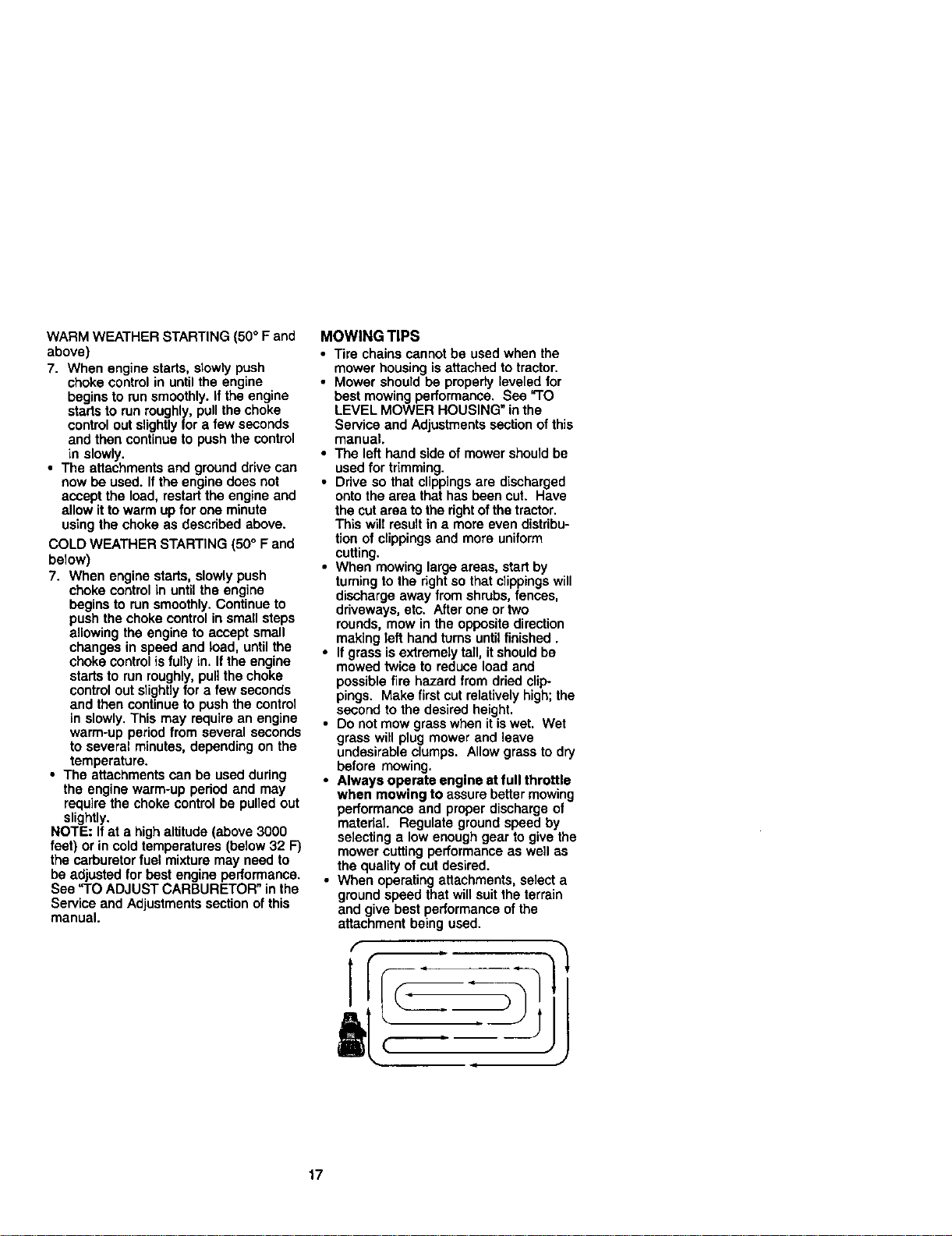
• Ddve so that clippingsare discharged
onto the area that has been cut. Have
the cut area tothe rightof the tractor,
This will result in a more even distribu-
tion of clippings and more uniform
cutting.
• When mowing large areas, start by
turningto the dght so that clippingswill
discharge away from shrubs, fences,
driveways, etc. After one or two
rounds, mow in the opposite direction
making left hand turns untilfinished.
• If grass isextremely tail, itshould be
mowed twice to reduce load and
possiblefire hazard from dried clip-
pings. Make firstcut relativelyhigh; the
second to the desired height.
• Do not mow grass when it iswet. Wet
grass will plug mower and leave
undesirable clumps. Allow grass to dry
before mowing.
• Always operate engine at full throttle
when mowing to assure better mowing
performance and proper discharge of
material Regulate ground speed by
selecting a low enough gear to give the
mower cutting performance as well as
the quality of cut desired.
• When operating attachments, select a
ground speed that will suit the terrain
and give best performance of the
attachment being used.
17
2 - _ mo_) orlon whim _adng In _dy or dully co_J_o_a.
3 • ff _0p_I _ o4 filler, ohange C_l ov_/50 hO4JrL
4 - _ t_ad_b rnorI often _ mo_no Y_ iandy _,
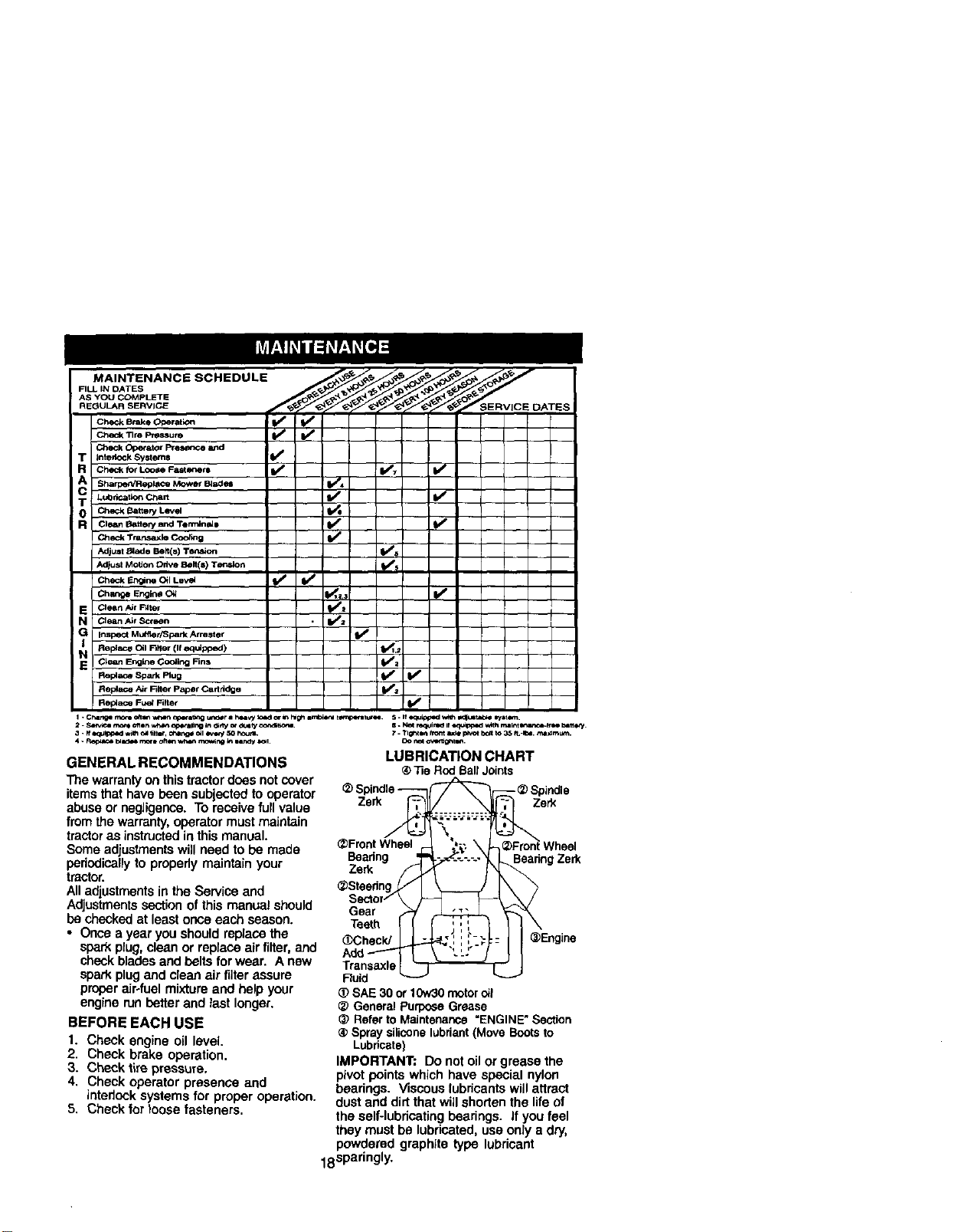
GENERAL RECOMMENDATIONS
The warrantyon thistractor does not cover
itemsthat have been subjected to operator
abuse or negligence. To receive fullvalue
fromthe warranty,operator must maintain
tractoras instructedin this manual.
Some adjustmentswill need to be made
periodicallyto properly maintain your
tractor.
All adjustmentsin the Service and
Adjustmentssection ofthis manual should
be checked at least once each season.
• Once a year you should repiaoe the
spark plug,clean or replace air filter,and
check blades andbelts forwear, A new
spark plugand dean air filterassure
proper air-fuel mixture and help your
engine run better and tast longer.
BEFORE EACH USE
1. Check engine oil level.
2. Check brake operation,
3. Check tire pressure.
4. Check operator presence and
intedock systems for proper operation.
5, Check for loose fasteners,
8. _ roq_Ji_ if I(:IVl_Oed w4h r_Bi_t _Fr_ b_e_.
?. l_gh_ h_r_ a_k_ p_,ot bo_ _o 35 _-_. mmamu_.
LUBRICATION CHART
®Tie RodBallJoints
Spindle_
Zerk/_ Zerk
\
_)FrontWheel .--
Bearing -'_ _.-_._.-.-_ BearingZerk
@Steering.,,(,'/ I
Sector/\ )=
Gear _
Tee .II i"!,
(_CheckJ L,_.!....:-,-=1-,[.,: ,_';
Transaxle
Fluid
_) SAE30 or10w30motoro_l
@ GeneralPurposeGrease
_) RefertoMaintenance"ENGINE"Section
@Spraysiliconelubriant(Move Bootsto
Lubricate)
IMPORTANT: Do not oil or grease the
pivot points which have special nylon
bearings. Viscous lubricants will attract
dust and dirtthat will shortenthe life of
the self-lubricatingbearings. If you feel
they must be lubricated, use only a dry,
powdered graphite type lubricant
18sparingly.
TRACTOR
Always observe safety rules when
performing any maintenance.
BRAKE OPERATION
If tractorrequires more than six (6) feet
stopping distance at high speed in
highest gear, then brake must be ad-
justed. (See "TO ADJUST BRAKE" in the
Service and Adjustments section of this
manuat).
TIRES
• Maintain proper air pressure in all tires
(See "PRODUCT SPECIFICATIONS"
section of this manual).
• Keep tires free of gasoline, oil, or insect
control chemicals which can harm
rubber.
• Avoid stumps, stones, deep ruts, sharp
objects and other hazards that may
cause tire damage.
NOTE: To seal tire punctures and prevent
flat tires due to slow leaks, tire sealant
may be purchasedfrom your local parts
dealer. Tire sealant also prevents tiredry
rotand corrosion.
OPERATOR PRESENCE SYSTEM
Be sure operator presence and interrock
systems are working properly. If your
tractor does not function as described,
repair the problem immediately.
• The engine should not start unless the
clutch/brake pedal is fully depressed
and attachement clutchcontrol is in the
disengaged position.
• When the engine is running, any
attempt by the operator to leave the
seat without first setting the parking
brake should shut off the engine.
• When the engine is running and the
attachment clutch is engaged, any
attempt by the operator to leave the
seat should shut off the engine.
• The attachment clutch should never
operate unless the operator is in the
seat.
BLADE CARE
For best resultsmower blades must be
kept sharp. Replace bent or damaged
blades.
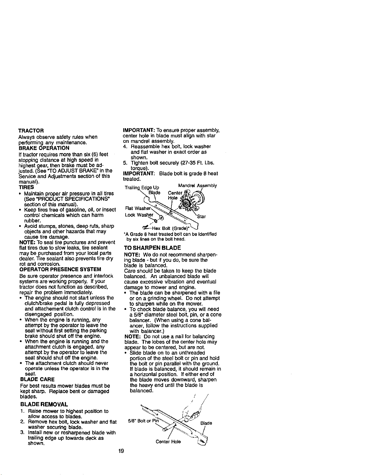
BLADE REMOVAL
1. Raise mower to highest positionto
allow access to blades.
2. Remove hex bolt, lock washer and flat
washer securing blade.
3. Install new or resharpened blade with
trailing edge up towards deck as
shown.
IMPORTANT: To ensure proper assembly,
center hole in blade must align with star
on mandrel assembly.
4. Reassemble hex bolt, lock washer
and flat washer in exact order as
shown.
5. Tighten bolt securely (27-35 Ft. Lbs.
torque).
IMPORTANT: Blade boltis grade 8 heat
treated.
EdgeUp MandrelAssembly
Center
Hole
19
Lock Washer
_--"_Hex Bolt (Grade)'
*A Grade 8 heat treated bolt can be identified
by six lines on the bolt head.
TO SHARPEN BLADE
NOTE: We do not recommend sharpen-
ing blade ÷but if you do, be sure the
blade is balanced.
Care should be taken to keep the blade
balanced. An unbalanced blade will
cause excessive vibration and eventual
damage to mower and engine.
• The blade can be sharpened with a file
or on a grindingwheel. Do not attempt
to sharpen while on the mower.
• To check blade balance, you will need
a 5/8" diameter steel bolt, pin, or a cone
balancer. (When using a cone bal-
ancer, follow the instructionssupplied
with balancer.)
NOTE: Do not use a nail for balancing
blade. The lobes ofthe center hole may
appear to be centered, but are not.
• Slide blade on to an unthreaded
portion of the steel bolt or pin and hold
the bolt or pin parallel with the ground.
If blade is balanced, it should remain in
a horizontal position. If either end of
the blade moves downward, sharpen
the heavy end untilthe blade is
balanced.
/
5/8"BoltorPin _ Blade
Center Hole _
BA'I-rERY
Your tractorhas a battery charging system
which is sufficientfor normal use. How-
ever, pedodic charging of the battery with
an automotive charger will extend its life.
• Keep battery and terminals clean.
• Keep battery bolts tight.
• Keep small vent holes open.
• Recharge at 6-10 amperes for 1 hour.
NOTE: The original equipment battery on
your tractor is maintenance free. Do not
attempt to open or remove caps or covers.
Adding or checking level of electrolyte is
not necessary.
TO CLEAN BA'I-]'ERY AND TERMINALS
Corrosion and dirt on the battery and
terminals can cause the battery to "leak"
power.
1. Remove terminal guard.
2. Disconnect BLACK battery cable first
then RED battery cable and remove
batteryfrom tractor.
3. Rinse the battery with plain water and
dry.
4. Clean terminals and battery cable
ends with wire brush until bright.
5, Coat terminals with grease or petro-
leum ielly.
6. Reinstall battery (See "REPLACING
BATTERY" in the SERVICE AND
ADJUSTMENTS section of this
manual).
V-BELTS
Check V-belts for deterioration and wear
after 100 hours of operation and replace
if necessary.The belts are not adjustable.
Replace belts if they begin to slip from
wear.
TRANSAXLE COOLING
Keep transaxle free from build+upof dirt
and chaff which can restrictcooling.
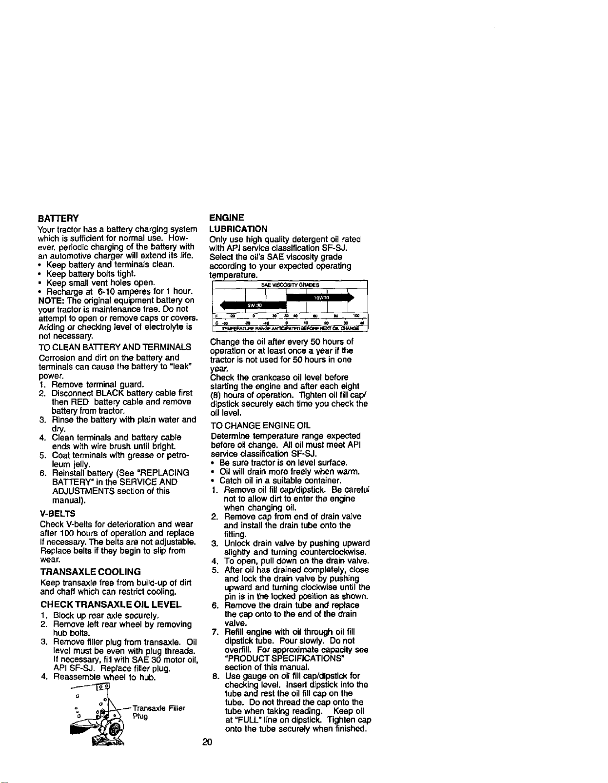
CHECK TRANSAXLE OIL LEVEL
1. Block up rear axle securely.
2. Remove left rear wheel by removing
hub bolts.
3. Remove filler plug from transaxle. Oil
level must be even with plug threads.
If necessary, fill with SAE 30 motor oil,
API SF-SJ. Replace filler plug.
4. Reassemble wheel to hub.
o
Filler
-=
o Plug
ENGINE
LUBRICATION
Only use high quality detergent oil rated
with API service classificationSF-SJ.
Select the oil'sSAE viscosity grade
according to your expected operating
temperature.
S/dEVIrK_C61/YGRADES
F _ o _,O _= 4O m m lm_
Change the oil after every 50 hours of
operation or at least once a year if the
tractor is not used for 50 hours in one
year.
Check the crankcase oil level before
startingthe engine and after each eight
(8) hours of operation. Tighten oil fill cap/
dipsticksecurely each time you check the
oil level.
TO CHANGE ENGINE OIL
Determine temperature range expected
before oil change. All oil must meet API
service classification SF-SJ.
• Be sure tractor iS on level surface.
• Oil will drain more freely when warm.
• Catch oil in a suitable container.
1. Remove oil fill cap/dipstick. Be careful
not to allow dirt to enter the engine
when changing oil.
2. Remove cap from end of drain valve
and install the drain tube onto the
fitting.
3. Unlock drain valve by pushing upward
slightly and turning counterclockwise.
4. To open, pull down on the drain valve.
5. After oil has drained completely, close
and lock the drain valve by pushing
upward and turning clockwise until the
pin is in the locked positionas shown.
6. Remove the drain tube and replace
the cap onto tothe end of the drain
valve.
7. Refill engine with oil through oil fill
dipstick tube. Pour slowly. Do not
overfill For approximate capacity see
=PRODUCT SPECIFICATIONS"
section of this manual.
8. Use gauge on oil fill cap/dipstickfor
checking level, Insert dipstick intothe
tube and rest the oil fill cap on the
tube, Do not thread the cap onto the
tube when taking reading. Keep oil
at "FULL" lineon dipstick. Tighten cap
onto the tube securely when finished.
2O
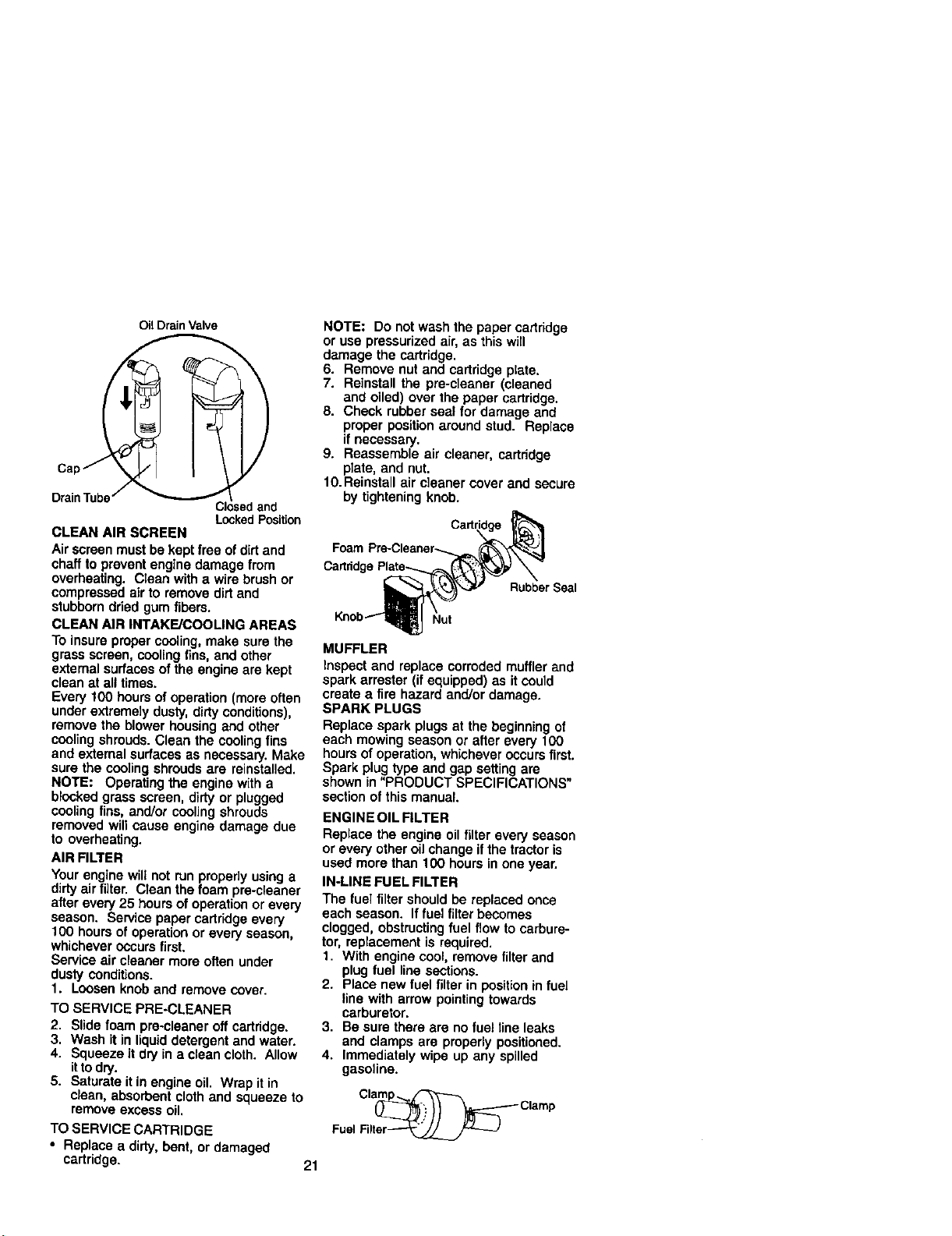
cap
DrainTubej
OilDrain Valve
)'?
_""-'_C osedand
LockedPosition
CLEAN AIR SCREEN
Air screen must be kept free of dirt and
chaff to prevent engine damage from
overheating. C_eanwith a wire brush or
compressed airto remove dirtand
stubborndried gum fibers.
CLEAN AIR INTAKE/COOLING AREAS
To insure proper cooling, make sure the
grass screen, cooling fins, and other
external surfaces of the engine are kept
clean at all times.
Every 100 hours of operation (more often
under extremely dusty, dirty conditions),
remove the blower housing and other
coolingshrouds. Clean the cooling fins
and external surfaces as necessary. Make
sure the cooling shrouds are reinstalled.
NOTE: Operating the engine with a
blocked grass screen, dirty or plugged
cooling fins, and!or cooling shrouds
removed will cause engine damage due
to overheating.
AIR FILTER
Your engine wiU not run preperly using a
dirty airfilter. Clean the foam pre-cleaner
after every 25 hours of operation or every
season. Se_ce paper cartridge every
100 hours of operation or every season,
whichever occurs first.
Service air cleaner more often under
dusty conditions.
1. Loosen knob and remove cover.
TO SERVICE PRE-CLEANER
2, Slide foam pre-cleaner off cartridge.
3. Wash it in liquiddetergent and water.
4. Squeeze it dry in a ctean cloth. Allow
itto dry.
5. Saturate it in engine oil. Wrap it in
clean, absorbent cloth and squeeze to
remove excess oil.
TO SERVICE CARTRIDGE
• Replace a dirty, bent, or damaged
cartridge.
21
NOTE: Do not wash the paper cartridge
or use pressurized air, as this win
damage the cartridge.
6. Remove nut and cartridge plate.
7. Reinstall the pre-cleaner (cleaned
and oiled) over the paper cartridge.
S. Check rubberseal for damage and
proper position around stud. Replace
if necessary.
9. Reassemble air cleaner, cartridge
plate, and nut.
10.Reinstal_ air cleaner cover and secure
by tightening knob.
Foam F
Cartddge
Rubber Seal
Nut
MUFFLER
Inspect and replace corroded muffler and
spark arrester (if equipped) as it could
create a fire hazard and/or damage.
SPARK PLUGS
Replace spark plugs at the beginning of
each mowing season or after every 100
hours of operation,whichever occursfirst.
Spark plug type and gap setting are
shown in "PRODUCT SPECIFICATIONS"
section of this manual
ENGINE OIL FILTER
Replace the engine oil filter every season
or every other oil change ifthe tractor is
used more than 100 hours in one year.
IN-LINE FUEL FILTER
The fuel filter should be replaced once
each season. Iffuel filter becomes
clogged, obstructingfuel flow to carbure-
tor, replacement is required.
1. With engine cool, remove filter and
plug fuel line sections.
2. Place new fuel filter in position in fuel
line with arrow pointing towards
carburetor.
3. Be sure there are no fuel line leaks
and clamps are properly positioned.
4. Immediately wipe up any spilled
gasoline.
Cl_clarnp
Fuel Filter_
CLEANING
• Clean engine, battery, seat, finish, etc.
of all foreign matter.
• Keep finished surfaces and wheels tree
of all gasoline, oil, etc.
• Protect painted surfaces with automo-
tive type wax.
We do not recommend using a garden
hose to clean your tractor unless the
electrical system, muffler, air filter and
carburetor are covered to keep water out.
Water in engine can result in a shortened
engine life.
A CAUTION: BEFORE PERFORMING ANY SERVICE OR ADJUSTMENTS:
1. Depress clutch/brake pedal fully and set parking brake.
2. Place gearshift lever in neutral (N) position.
3. P_aceattachment clutch in =DISENGAGED" position.
4. Turn ignitionkey "OFF" and remove key.
5, Make sure the blades and all moving parts have completely stopped.
6, Disconnect spark plug wire from spark plug and place wire where itcannot
come in contact with plug.
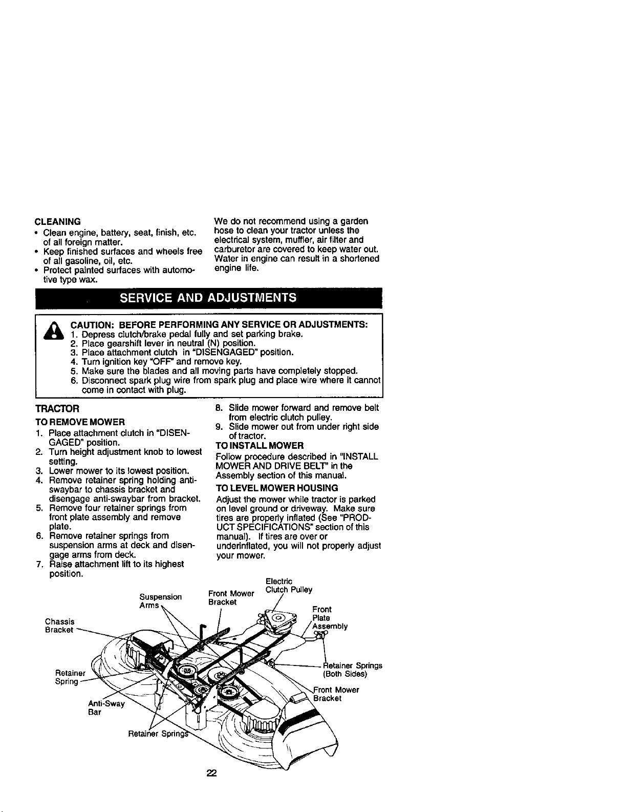
TRACTOR
TO REMOVE MOWER
1. Place attachment clutch in "DISEN-
GAGED" position.
2. Turn height adjustment knob to lowest
setting.
3. Lower mower to its lowest position.
4. Remove retainer spring holding anti-
swaybar to chassis bracket and
disengage anti-swaybar from bracket.
5. Remove four retainer springs from
front plate assembly and remove
plate.
6. Remove retainer springs from
suspension arms at deck and disen-
gage arms from deck.
7. Raise attachment lift to its highest
position.
Suspension
Chassis
8. Slide mower forward and remove belt
from electdc clutch pulley.
9. Slide mower out from under rightside
oftractor.
TO INSTALL MOWER
Follow procedure described in "INSTALL
MOWER AND DRIVE BELT"in the
Assembly section of this manual.
TO LEVEL MOWER HOUSING
Adjustthe mower while tractor is parked
on level groundor driveway. Make sure
tires are propedy inflated (See "PROD-
UCT SPECIFICATIONS" section ofthis
manual). If tiresare over or
underinflated, you will not properly adjust
your mower.
Electric
Front Mower Clutch Pulley
Bracket
Front
Plate
Retainer
Sprin
Anti-Sway
Bar
_pdngs
(Both Sides)
Bracket
22
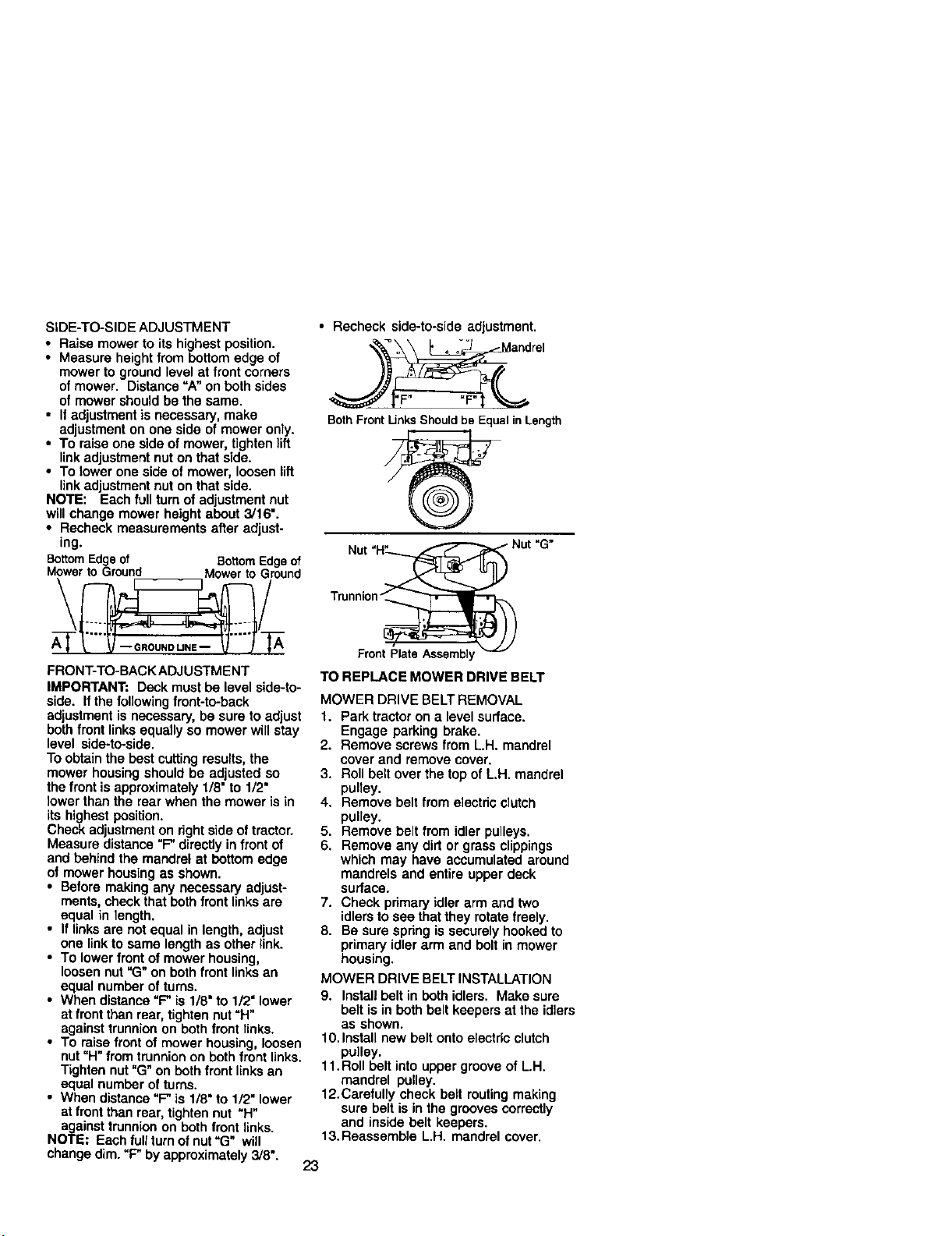
SIDE-TO-SIDE ADJUSTMENT
• Raise mower to its highest position.
• Measure height from bottom edge of
mower to ground level at front corners
of mower. Distance "A" on both sides
of mower should be the same.
• I1adjustment is necessary, make
adjustment on one side of mower ooly.
• To raise one side of mower, tighten lift
link adjustment nut on that side.
• To lower one side of mower, loosen lift
link adjustment nut on that side.
NOTE: Each full turn of adjustment nut
will change mower height about 3/16".
• Recheck measurements after adjust-
ing.
BottomEdgeof BottomEdgeof
Mowerto Ground Mower to Ground
\ /
FRONT-TO-BACK ADJUSTM ENT
IMPORTANT; Deck must be level side-to-
side. If the following front-to-back
adjustment is necessary, be sure to adjust
both front links equally so mower will stay
level side-to-side.
To obtain the best cuttingresults, the
mower housing should be adjusted so
the front is approximately 1/8" to 1/2"
lower than the rear when the mower is in
its highest position.
Check adjustmenton rightside of tractor.
Measure distance "F"directly in front of
and behind the mandrel at bottom edge
of mower housing as shown.
• Before making any necessary adjust-
ments, check that both front links are
equal in length.
• If links are not equal in length, adjust
one linkto same length as other link.
• To lower front of mower housing,
loosen nut"G" on both front links an
equal number ofturns.
• When distance"F" is 1/8" to 1/2" lower
at front than rear, tighten nut=H"
against trunnionon both front links.
• To raise front of mower housing, loosen
nut"H" from trunnionon both front links.
"lighten nut"G" on both front links an
equal number ofturns.
• When distance"F" is 1/8" to 1/2" lower
at front than rear, tighten nut "H"
against trunnionon both front links.
NOTE; Each full turn ofnut"G" will
change dim. "F" by approximately 3/8".
• Recheck side-to-side adjustment.
_ r
o o o and el
BothFrontUnks Shouldbe EqualinLength
Nut "1-1"_
Trunnion _,_
Front Plate Assemb]
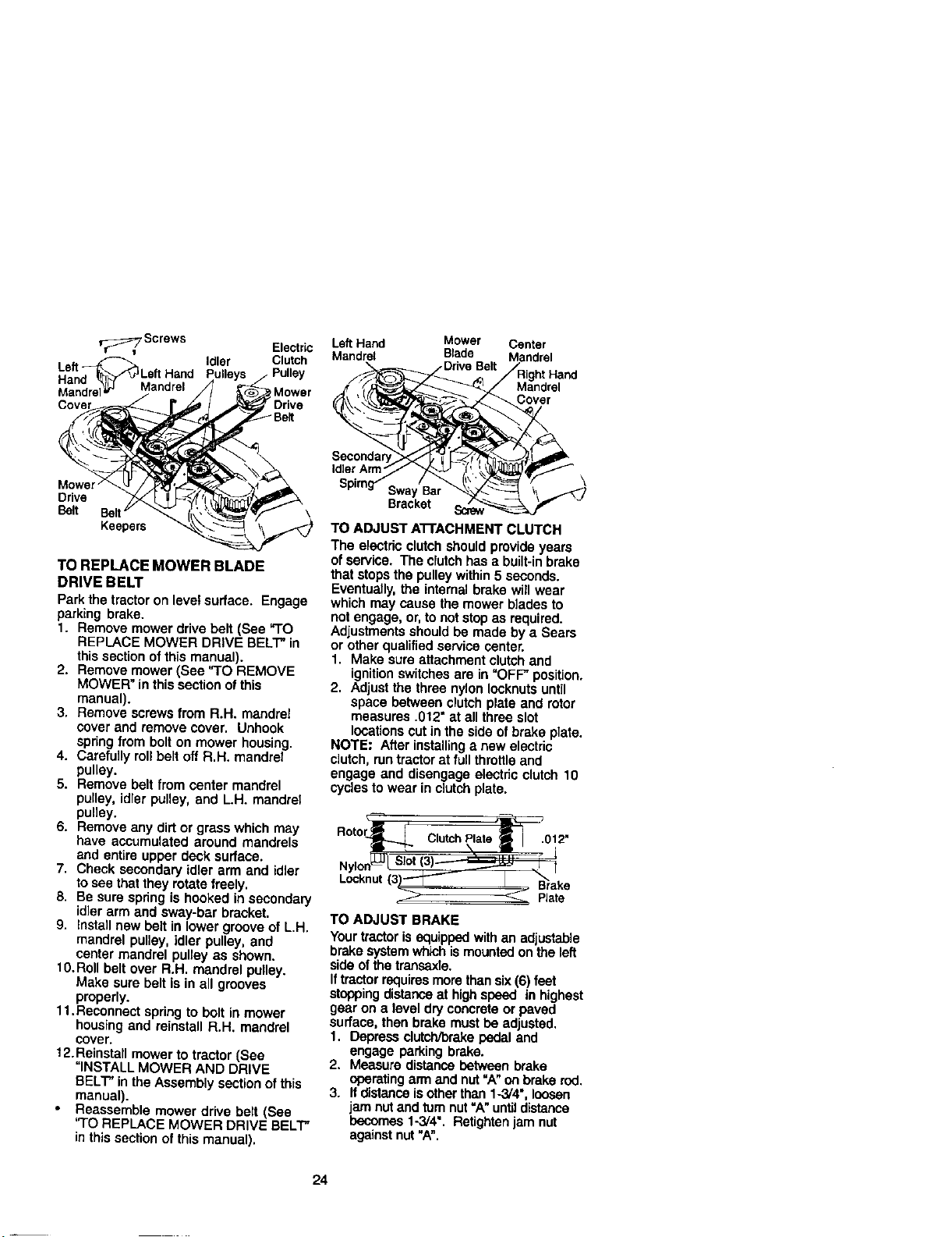
TO REPLACE MOWER DRIVE BELT
MOWER DRIVE BELT REMOVAL
1. Park tractor on a level surface.
Engage parking brake.
2. Remove screws from L.H. mandrel
cover and remove cover.
3. Roll belt over the top of L.H. mandrel
pulley.
4. Remove belt from electdc clutch
pulley.
5. Remove belt from idler pulleys.
6. Remove any dirt or grass clippings
which may have accumulated around
mandrels and entire upper deck
surface.
7. Check primary idler arm and two
idlers to see that they rotate freely.
8. Be sure spring is securely hooked to
primary idler arm and bolt in mower
housing.
MOWER DRIVE BELT INSTALLATION
9. Install belt in both idlers. Make sure
belt is in both belt keepers at the idlers
as shown.
10. Install new belt onto electric clutch
pulley.
11.Roll belt into upper groove of L.H.
mandrel pulley.
12.Carefully check belt routing making
sure belt is in the grooves correctly
and inside belt keepers.
13.Reassemble LH. mandrel cover.
23
Screws Electric
L.eftn,_-_ Idler Crutch
Left Hand Pulley
Ha o'_" Mandrel
Mandrel t Mower
Drive
Bert
Left Hand Mower Center
Mandrel Blade Mandrel
Mandrel
Cover
Mower
Drive
Belt
BeR \
Keepers
TO REPLACE MOWER BLADE
DRIVE BELT
Park the tractoron levef surface. Engage
parking brake.
1. Remove mower drive belt (See "TO
REPLACE MOWER DRIVE BELT" in
this section of this manual).
2. Remove mower (See "TO REMOVE
MOWER" in this section of this
manual).
3. Remove screws from R.H. mandre_
cover and remove cover. Unhook
spring from bolt on mower housing.
4. Carefully rol_belt off R.H. mandrel
pulley.
5. Remove belt from center mandrel
pulley, idler pulley, and L.H. mandrel
pulley.
6. Remove any dirt or grass which may
have accumulated around mandrels
and entire upper dock surface.
7. Check secondary idler arm and idler
to see that they rotate freely.
8. Be sure spdng is hooked in secondary
idler arm and sway-bar bracket.
9. Install new belt in lower groove of L.H.
mandrel pulley, idler pulley, and
center mandrel pulley as shown.
10.Roll belt over R.H, mandrel pulley.
Make sure belt is in all grooves
properly.
11.Reconnect spring to bolt in mower
housing and reinstall R.H. mandrel
cover.
12. Reinstallmower to tractor (See
=INSTALL MOWER AND DRIVE
BELT" in the Assembly section of this
manual).
Reassemble mower drive belt (See
"TO REPLACE MOWER DRIVE BELT"
in this section of this manual).
Idler Arm
\
SwayBar
Bracket
TO ADJUST A'n'ACHMENT CLUTCH
The eloctdc clutch should provide years
of service. The clutchhas a built-inbrake
that stops the pulley within 5 seconds.
Eventually, the internal brake will wear
which may cause the mower blades to
not engage, or, tonot stopas required.
Adjustments should be made by a Sears
or other qualified service center.
1. Make sure attachment clutch and
ignitionswitches are in =OFP" position.
2. Adjust the three nylon Iocknutsuntil
space between clutch plate and rotor
measures .012" at artthree stot
locations cut in the side ofbrake plate.
NOTE: After installinga new electric
clutch, runtractor at full throttle and
engage and disengage electric clutch 10
cycles to wear in clutch plate.
Oo,or :C
Locknut(3}"-_ B'_ake
_ Plate
TO ADJUST BRAKE
Your tractoris equippedwith an adjUS'l.:_e
brake systemwhich ismountedon the left
side ofthe transaxle,
Iftractor requiresmore thansix (6) feet
stoppingdistanceat highspeed in highest
gear on a level dry concrete or paved
surface, then brake must be adjusted.
1. Depress clutch/brake pedal and
engage parking brake.
2. Measure distance between brake
operating arm and nut "A" on brake red.
3. Ifdistance is other than 1-3/4", loosen
jam nut and rum nut =A"untildistance
becomes 1-3/4". Ratighten jam nut
against nut "A".
24
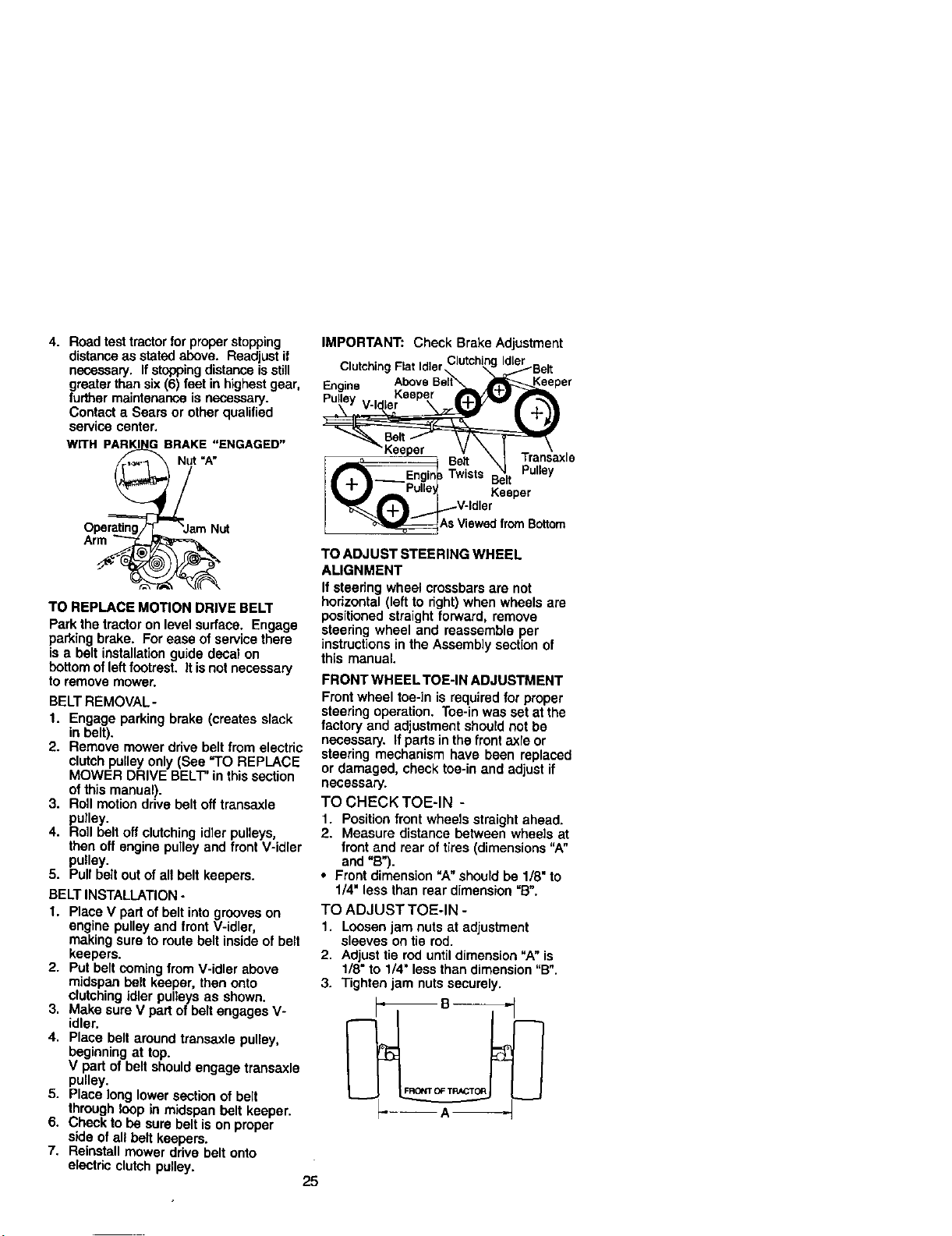
4. Road test tractor tor proper stopping
distanceas statedabove. Readjust if
necessary. If stoppingdistanceisstill
greater than six (6) feet in highestgear,
further maintenance is necessary.
Contact a Sears or other qualified
service center.
PAR I ( BRAKE "ENGAGED"
WITH __ _=_///_t"A"
Operating,, "JamN_
TO REPLACE MOTION DRIVE BELT
Park the tractor on level sudace. Engage
parking brake. For ease of service there
is a belt installation guide decal on
bottom of leftfootrest. It is not necessary
to remove mower.
BELT REMOVAL-
1. Engage parking brake (creates slack
in belt).
2. Remove mower drive belt from electric
clutch pulley only (See "TO REPLACE
MOWER DRIVE BELT" in this section
of this manual).
3. Roll motion drive belt off transaxle
pulley.
4. Roll belt oft clutching idler pulleys,
then off engine pulley and front V-idler
pulley.
5. Pull belt out of all belt keepers.
BELT INSTALLATION -
1. Place V part ofbelt into grooves on
engine pulley and front V-idler,
making sure to route belt Inside of belt
keepers.
2. Put belt coming from V-idler above
mldspan belt keeper, then onto
clutchingidler pulleys as shown.
3. Make sure V part of belt engages V-
idler.
4. Place belt around transaxle pulley,
beginning at top,
V part of belt should engage transaxle
pulley.
5. Place long lower section of belt
through loop in midspan belt keeper.
6. Check to be sure belt is on proper
side of all belt keepers.
7. Reinstall mower drive belt onto
electdc clutch pulley.
25
IMPORTANT: Check Brake Adjustment
ClutchingFlatIdlerClutchingIdlerBelt
n . AboveBelt Keeper
_xle
_'J _=b ru"u_ Keeper
_vV;:_ from Bottom
TO ADJUST STEERING WHEEL
ALIGNMENT
If steering wheel crossbars are not
horizontal (leftto right)when wheels are
positioned straight forward, remove
steering wheel and reassemble per
instructions in the Assembly section of
this manual.
FRONT WHEEL TOE-IN ADJUSTMENT
Frontwheel toe-in is required for proper
steering operation. Toe-in was set at the
factory and adjustment should not be
necessary. If partsin the front axle or
steering mechanism have been replaced
or damaged, check toe-in and adjust if
necessary.
TO CHECK TOE-IN -
1. Position front wheels straight ahead.
2. Measure distance between wheels at
front and rear of tires (dimensions "A"
and =B").
• Front dimension "A" should be 1/8" to
1/4" less than rear dimension "B".
TO ADJUST TOE-IN -
1. Loosen jam nuts at adjustment
sleeves on tie rod.
2. Adjust tie rod until dimension "A" is
1/8" to 1/4" less than dimension "B".
3. Tighten jam nuts securely.
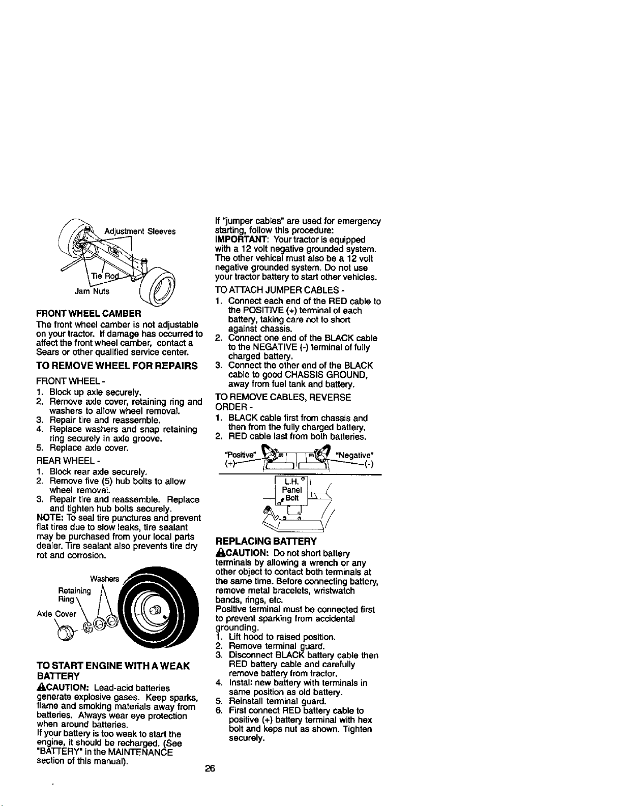
Adjustment Sleeves
Jam Nuts
FRONT WHEEL CAMBER
The front wheel camber is not adjustable
on your tractor. If damage has occurred to
affect the frontwheel camber, contact a
Sears or other qualified service center.
TO REMOVE WHEEL FOR REPAIRS
FRONT WHEEL -
1. Block up axle securely.
2. Remove axle cover, retaining ring and
washers to allow wheel removal.
3. Repair tire and reassemble.
4. Replace washers and snap retaining
ring securely in axle groove.
5. Replace axle cover.
REAR WHEEL -
1. Block rear axle securely.
2. Remove five (5) hub bolts to allow
wheel removal.
3. Repair tire and reassemble. Replace
and tighten hub bolts securely.
NOTE: To seal tire punctures and prevent
fiat tires due toslow leaks, tire sealant
may be purchased from your local parts
dealer. Tire sealant also prevents tire dry
rot and corrosion.
RetainingWa_rsA
+
TO START ENGINE WITH A WEAK
BAI-I'ERY
ACAUTION: Lead-acid batteries
generate explosive gases. Keep sparks,
flame and smoking materials away from
batteries. Always wear eye protection
when around batteries.
If yourbattery istoo weak to start the
engine, it should be recharged. (See
"BA'I-FERY"inthe MAINTENANCE
section ol this manual).
If =jumper cables"are used for emergency
starting, follow this procedure:
IMPORTANT: Your tractoris equipped
with a 12 volt negative grounded system.
The other vehical must also be a 12 volt
negative grounded system. Do notuse
your tractor battery tostart othervehicles.
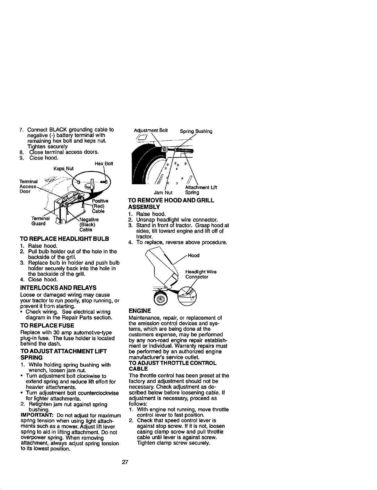
TO A'I-]'ACH JUMPER CABLES -
1. Connect each end of the RED cable to
the POSITIVE (+) terminal ofeach
battery, taking care not to short
against chassis.
2. Connect one end of the BLACK cable
to the NEGATIVE (-) terminal of fully
charged battery.
3. Connect the other end of the BLACK
cable to good CHASSIS GROUND,
away from fuel tank and battery.
TO REMOVE CABLES, REVERSE
ORDER -
1. BLACK cable first from chassis and
then fromthe fully charged battery.
2. RED cable last from both batteries.
"PosPd__ "Negative+
(+)"'_/i_::::Z_IC_Z:_-"""_- (-)
Panel
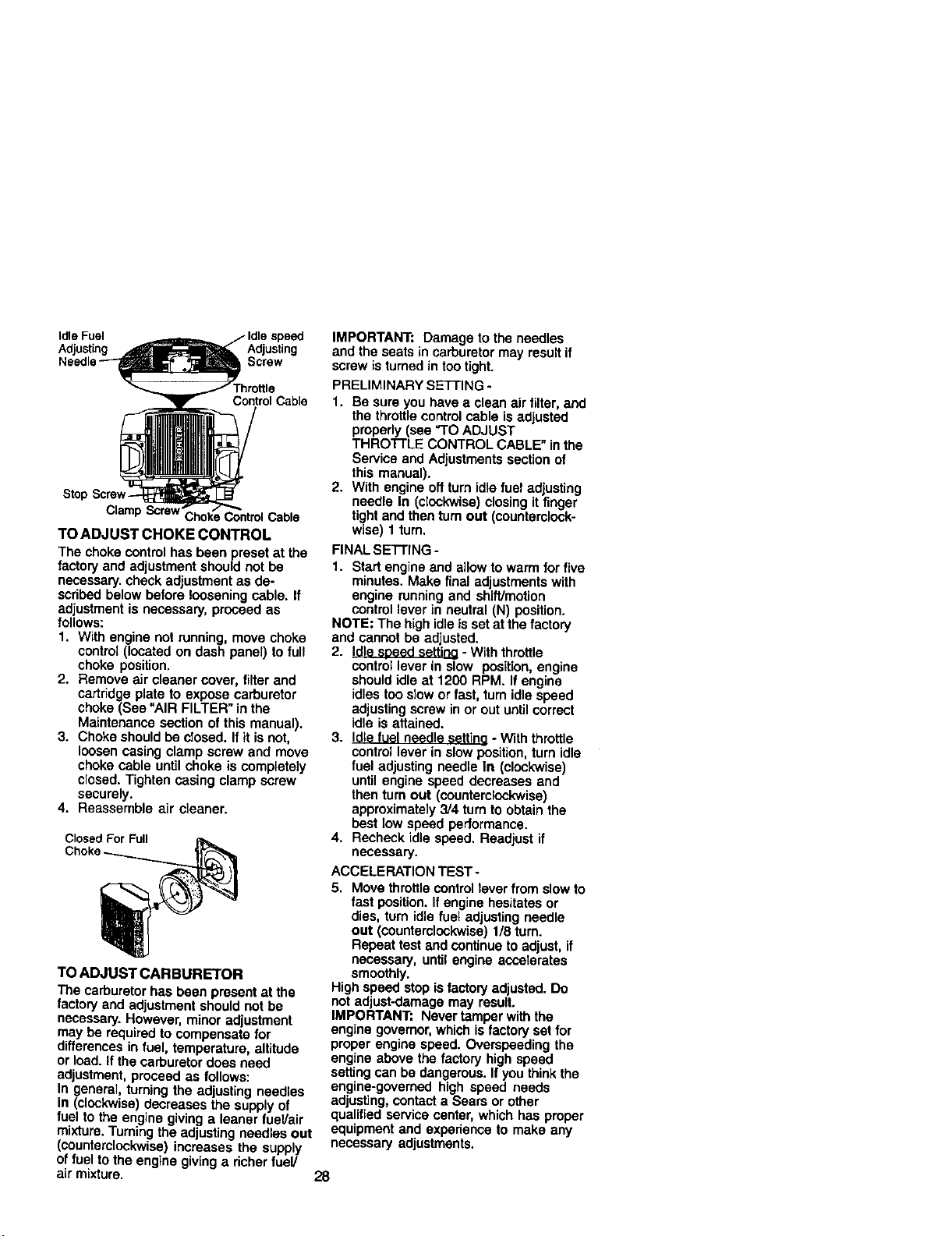
REPLACING BATTERY
_CAUTION: DOnot shortbattery
terminals by allowing a wrench or any
other objectto contact both terminalsat
the same time. Before connecting battery,
remove metal bracelets, wristwatch
bands, rings,etc.
Positiveterminal must be connected first
to prevent sparking from accidental
grounding.
1. Lift hood to raised position.
2. Remove terminal guard.
3. Disconnect BLACK battery cable then
RED battery cable and carefully
remove battery lrom tractor.
4. Install new battery with terminals in
same positionas old battery.
5. Reinstall terminal guard.
6. First connect RED battery cable to
positive (+) battery terminal with hex
boltand keps nut as shown. Tighten
securely.
26
7. Connect BLACK grounding cable to
negative (-) battery terminal with
remaining hex bolt and keps nut.
Tighten securely
8. Close terminal access doors.
9. Close hood.
HexBolt
KepsNut
AdjustmentBolt Spring
Terminal
Access ..' ,..
Door _
Positive
":" Cable
Terminal
Guard (Black)
Cable
TO REPLACE HEADLIGHT BULB
1. Raise hood.
2. Pull bulb holder out of the hole in the
backside of the gd]l.
3. Replace bulb in holder and push bulb
holdersecurely back into the hole in
the backside of the grill.
4. Close hood.
INTERLOCKS AND RELAYS
Loose or damaged wiring may cause
your tractor to run poorly,stop running, or
prevent itfrom starting.
• Check wiring. See electrical wiring
diagram in the Repair Parts section.
TO REPLACE FUSE
Replace with 30 amp automotive-type
plug-infuse. The fuse holder islocated
behind the dash.
TO ADJUST ATTACHMENT LIFT
SPRING
1. While holding spring bushing with
wrench, loosen jam nut.
• Turn adjustment boltclockwise to
extend spring and reduce lifteffort for
heavier attachments.
• Turn adjustment bolt counterclockwise
for lighter attachments.
2. Retighten jam nut against spring
bushing.
IMPORTANT: Do not adjust for maximum
spring tension when using light attach-
ments such as a mower. Adjust liftlever
spnng to aid in liftingattachment. Do not
overpower spring. When removing
attachment, always adjust spring tension
to its lowest position.
//\
AttachmentLift
Jam Nut Spring
TO REMOVE HOOD AND GRILL
ASSEMBLY
1. Raise hoed.
2. Unsnap headlight wire connector.
3. Stand infront of tractor. Grasp hood at
sides, tilt toward engine and liftoff of
tractor.
4. To replace, reverse above procedure.
i nector
ENGINE
Maintenance, repair, or replacement of
the emission control devices and sys-
tems, which are being done at the
customers expense, may be performed
by any non-road engine repair establish-
ment or individual. Warranty repairs must
be performed by an authorized engine
manufacturer's service outlet.
TO ADJUST THRO'I-rLE CONTROL
CABLE
The throttlecontrol has been preset at the
factory and adjustment should not be
necessary. Check adjustment as de-
scribed below before loosening cable. If
adjustment is necessary, proceed as
follows:
1. With engine not running, move throttle
control lever to fast position.
2. Check that speed control lever is
against stop screw. If it is not, loosen
casing clamp screw and pull throttle
cable untillever is against screw.
Tighten clamp screw securely.
27
Idle Fuel speed
Adjusting Adjusting
Screw
Throttle
Control Cable
ClampScrew" ControlCable
TO ADJUST CHOKE CONTROL
The choke control has been preset at the
factory and adjustment should not be
necessary, check adjustment as de-
scribed below before loosening cable. If
adjustment is necessary, proceed as
follows:
1, With engine not running, move choke
control (located on dash panel) to full
choke position.
2, Remove air cleaner cover, filter and
cartridge plate to expose carburetor
choke (See "AIR FILTER" in the
Maintenance section of this manual).
3. Choke should be closed. If it is not,
loosen casing clamp screw and move
choke cable untilchoke is completely
closed. Tighten casing clamp screw
securely.
4. Reassemble air cleaner.
Closed For F_l
TO ADJUST CARBURETOR
The carburetor has been present at the
factory and adjustment should not be
necessary. However, minor adjustment
may be required to compensate for
differences in fuel, temperature, altitude
or load. If the carburetor does need
adjustment, proceed as follows:
In general, turning the adjusting needles
in (clockwise) decreases the supply of
fuel to the engine giving a leaner fuel/air
mixture. Turningthe adjusting needles out
(counterclockwise) increases the supply
of fuel to the engine giving a richer fuel/
air mixture.
IMPORTANT: Damage to the needles
and the seats in carburetor may result if
screw is turned in tootight.
PRELIMINARY SETFING -
1. Be sure you have a clean air tilter, and
the throttle control cable is adjusted
properly (see "TO ADJUST
THRO'I-rLE CONTROL CABLE" in the
Service and Adjustments section of
this manual).
2. With engine off turn idle fuel adjusting
needle In (clockwise) closing it finger
tight and then turn out (counterclock-
wise) I turn.
FINAL SETI'ING -
1. Start engine and allow to warm for five
minutes. Make final adjustments with
engine running and shift/motion
control lever in neutral (N) position.
NOTE: The high idleis set at the factory
and cannot be adjusted.
2. Idle soeed settina - With throttle
control lever in slow position, engine
should idle at 1200 RPM. If engine
idles too slow or fast, turn idle speed
adjusting screw in or out until correct
idle is attained.
3. Idle f'_elneedle sett'lno- With throttle
control lever in slow position, turn idle
fuel adjusting needle In (clockwise)
until engine speed decreases and
then turn out (oounterclockwise)
approximately 3/4 turn to obtain the
best low speed performance.
4. Recheck idle speed. Readjust if
necessary.
ACCELERATION TEST-
5. Move throttle controllever from slow to
fast position. If engine hesitates or
dies, turn idle fuel adjusting needle
out (counterclockwise) 1/8 turn.
Repeat test and oontinu_ to adjust, if
necessary, until engine accelerates
smoothly.
High speed stop is factory adjusted. Do
not adjust-damage may result.
IMPORTANT= Never tamper with the
engine governor, which is factory set for
proper engine speed. Overspeeding the
engine above the factory high speed
setting can be dangerous. If you think the
engine-govemed high speed needs
adjusting, oontact a Sears or other
qualified service center, which has proper
equipment and expedenca to make any
necessary adjustments.
28
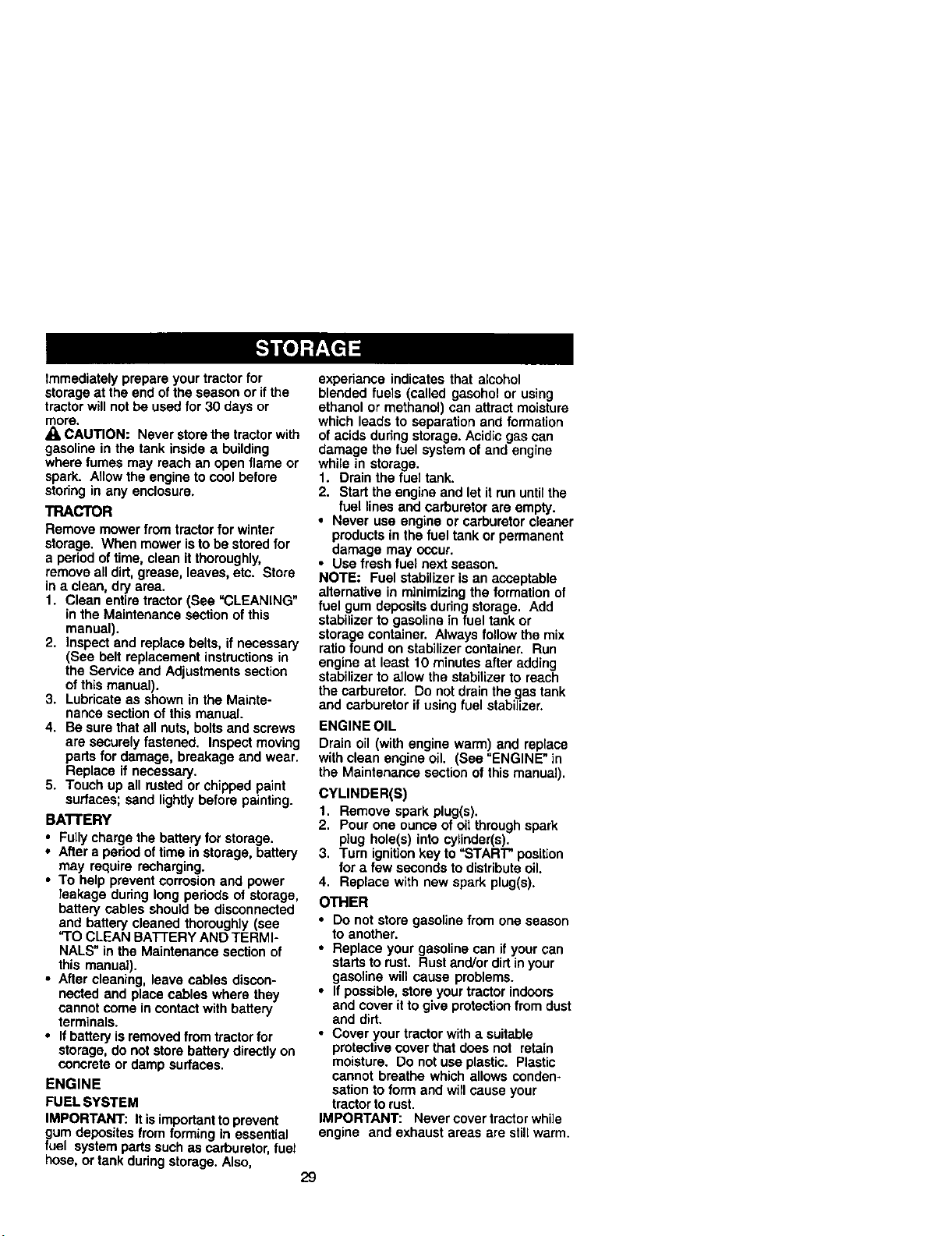
Immediately prepare your tractor for
storage at the end ofthe season or if the
tractor will not be used for 30 days or
more.
CAUTION: Never store the tractor with
gasoline in the tank inside a building
where fumes may reach an open flame or
spark. Allow the engine to cool before
storing in any enclosure.
TRACTOR
Remove mower from tractor for winter
storage. When mower is to be stored for
a period of time, clean it thoroughly,
remove all dirt, grease, leaves, etc. Store
in a clean, dry area.
1. Clean entire tractor (See =CLEANING"
in the Maintenance section of this
manual).
2. Inspect and replace belts, if necessary
(See belt replacement instructionsin
the Service and Adjustments section
ofthis manual).
3. Lubricate as shown in the Mainte-
nance section of this manual.
4. Be sure that all nuts, bolts and screws
are securely fastened. Inspect moving
parts for damage, breakage and wear.
Replace if necessary.
5. Touch up all rusted or chipped paint
surfaces; sand lightlybefore painting.
BAI-fERY
• Fullycharge the battery for storage.
• After a period oftime in storage, battery
may require recharging.
• To help prevent corrosion and power
leakage during long periods of storage,
battery cables should be disconnected
and battery cleaned thoroughly (see
"TO CLEAN BATFERY AND TERMI-
NALS" in the Maintenance section of
this manual).
• After cleaning, leave cables discon-
nected and place cables where they
cannot come in contactwith battery
terminals.
• If batteryis removed from tractorfor
storage, do not store battery directlyon
concrete or damp surfaces.
ENGINE
FUEL SYSTEM
IMPORTANT: It isimportantto prevent
gum deposites from forming in essential
fuel system parts such as carburetor, fuel
hose, or tank during storage. Also,
experiance indicates that alcohol
blended fuels (called gasohol or using
ethanol or methanol) can attract moisture
which leads to separation and formation
of acids during storage. Acidic gas can
damage the fuel system of and engine
while in storage.
1. Drain the fuel tank.
2. Start the engine and let it run until the
fuel lines and carburetor are empty.
• Never use engine or carburetor cleaner
products in the fuel tank or permanent
damage may occur.
• Use fresh fuel next season.
NOTE; Fuel stabilizer is an acceptable
alternative in minimizing the formation of
fuel gum deposits during storage. Add
stabilizer to gasoline in fuel tank or
storage container. Always follow the mix
ratio found on stabilizer container. Run
engine at least 10 minutes after adding
stabilizer to allow the stabilizer to reach
the carburetor. Do not drain the gas tank
and carburetor if using fuel stabilizer.
ENGINE OIL
Drain oil (with engine warm) and replace
with clean engine oil. (See "ENGINE" in
the Maintenance section of this manual).
CYLINDER(S)
1. Remove spark plug(s).
2. Pour one ounce of oil through spark
plug hole(s) into cylinder(s).
3. Turn ignitionkey to =START" position
for a few seconds to distributeoil.
4. Replace with new spark plug(s).
OTHER
• Do not store gasoline from one season
to another.
• Replace your gasoline can if your can
startsto rust. Rust and/or dirtin your
gasoline will cause problems.
• If possible, store your tractor indoors
and cover it to give protection from dust
and dirt.
• Cover your tractor with a suitable
protective cover that does not retain
moisture. Do not use plastic. Plastic
cannot breathe which allows conden-
sation to form and will cause your
tractor to rust.
IMPORTANT: Never cover tractor while
engine and exhaust areas are slill warm.
29
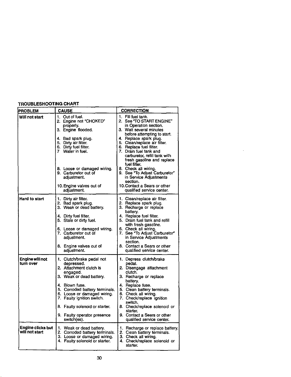
TROUBLESHOOTING CHART
=ROBLEM CAUSE
Will not start 1. Out of fuel.
Hard to start
Enginewlllnot
turn over
2. Engine not "CHOKED"
properly.
3. Engine flooded.
4. Bad spark plug.
5. Dirty air filter.
6. Dirty fuel filter.
7 Water in fuel.
8, Loose or damaged wiring.
9. Carburetor out of
adjustment.
10. Engine valves out of
adjustment,
1. Dirty air filter.
2, Bad spark plug.
3. Weak or dead battery.
4. Dirtyfuel filter.
5. Stale or dirty fuel.
6. Loose or damaged wiring,
7. Carburetor out of
adjustment.
8. Engine valves out of
adjustment.
1. Clutch/brake pedal not
depressed.
2. Attachment clutch is
engaged.
3. Weak or dead battery.
4. Blown fuse.
5. Corroded battery terminals.
6. Loose or damaged wiring.
7. Faulty ignition switch.
8. Faulty solenoid or starter.
9. Faulty operator presence
switch(es).
1. Weak or dead battery.
2. Corroded battery terminals.
3. Loose or damaged wiring.
4. Faulty solenoidor starter.
Engine clicks but
will not start
CORREC_ON
1. Fillfuel tank.
2. See "TO START ENGINE"
in Operation section.
3. Wait several minutes
before attempting tostart.
4. Replace spark plug.
5. Clean/replace air filter.
6. Replace fuel filter.
7. Drain fuet tank and
carburetor, refill tank with
fresh gasoline and replace
fuel filter.
8. Check all wiring.
9. See "ToAdjust Carburetor"
in Service Adjustments
section.
10.Contact a Sears or other
qualified service center.
1. Clean/replace air filter.
2. Replace spark plug.
3. Recharge or replace
battery.
4. Replace fuel filter.
5. Drain fuel tank and refill
with fresh gasoline.
6. Check sll wiring.
7. See "To Adjust Carburetor"
in Service Adjustments
section.
8. Contact a Sears or other
qualified service center.
1. Depress clutch/brake
pedal.
2. Disengage attachment
clutch.
3. Recharge or replace
battery.
4. Replace fuse.
5. Clean battery terminals.
6. Check all wiring.
7. Check/replace ignition
switch.
8. Check/replace solenoid or
starter.
g. Contact a Sears or other
qualified service center,
1. Recharge or replace battery
2. Clean battery terminals.
3. Check all wiring.
4. Check/replace solenoid or
starter.
3O
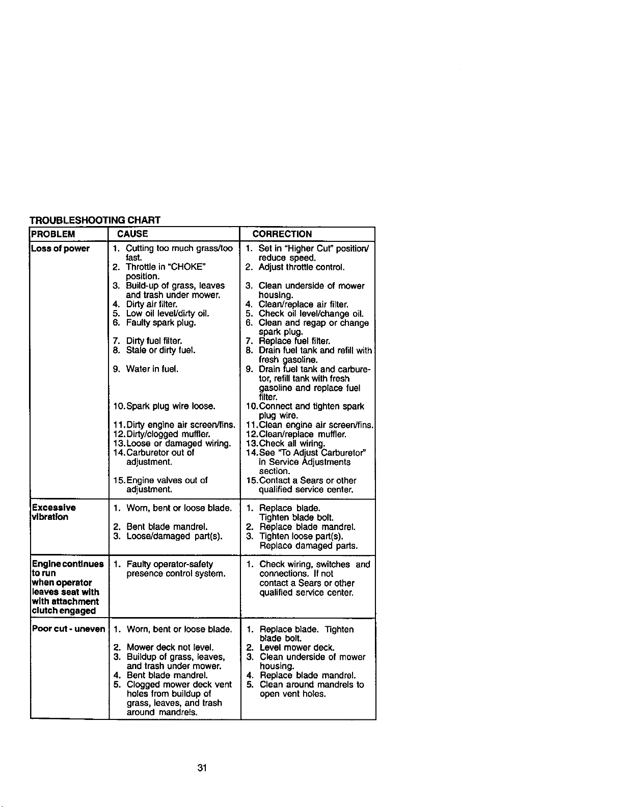
TROUBLESHOOTING CHART
PROBLEM
Loss of power
Excessive
vibration
CAUSE
1. Cutting too much grass!too
Englnecontlnues
to run
when operator
leaves seat with
with attachment
clutch engaged
Poor cut - uneven
fast.
i 2. Throttle in "CHOKE"
position.
3. Build-up of grass, leaves
and trash under mower.
4. Dirty airfilter.
5. Low oil level/dirty oil.
6. Faultyspark plug.
7. Dirty fuel filter.
8. Stale or dirty fuel
9. Water in fuel.
lO.Spark plug wire loose.
11.Dirty engine air screen/fins.
12. Dirty/clogged muffler.
13.Loose or damaged wiring.
14.Carburetor out of
adjustment.
15. Engine valves out of
adjustment.
1. Worn, bent or loose blade.
2. Bentblademandrel.
3. Loose/damagedpart(s).
1. Faulty operator-safety
presence control system.
1. Worn, bent or loose blade,
2. Mower deck not level.
3. Buildup of grass, leaves,
and trash under mower.
4. Bent blade mandrel.
5. Clogged mower deck vent
holes from buildup of
grass, leaves, and trash
around mandrels.
CORRECTION
1. Set in "Higher Cut" position/
reduce speed.
2. Adjust throttle control.
3. Clean underside of mower
housing.
4. Clean/replace air filter.
5. Check oil level/change oil.
6. Clean and ragap or change
spark plug.
7. Replace fuel filter.
8. Drain fuel tank and refillwith
fresh gasoline.
9. Drain fuel tank and carbure-
tor, refilltank withfresh
gasoline and replace fuel
filter.
10.Connect and tighten spark
plug wire.
11.Clean engine air screen/fins,
12.Clean/replace muffler.
13.Check all widng.
14.See "ToAdjust Carburetor"
in Service Adjustments
section.
15.Contact a Sears or other
qualified service center.
1. Replace blade.
Tighten blade bolt.
2. Replace blade mandrel.
3. Tighten loose part(s).
Replace damaged parts.
1. Check wiring, switches and
connections. If not
contact a Sears or other
qualified service center.
1. Replace blade. Tighten
blade bolt.
2. Level mower deck.
3, Clean underside of mower
housing.
4, Replace blade mandrel.
5. Clean around mandrels to
open vent holes.
31
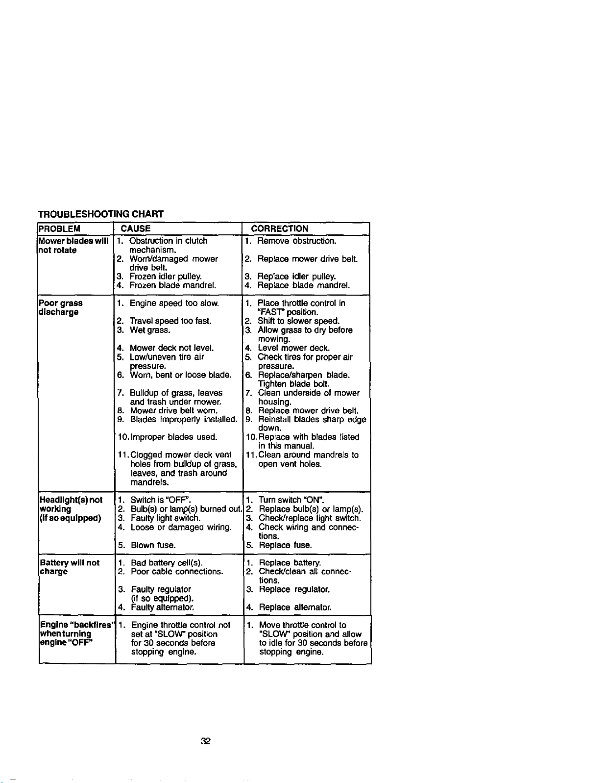
TROUBLESHOOTING CHART
PROBLEM CAUSE CORRECTION
Vlowerbladeswlll 1. Obstruction in clutch 1. Remove obstruction.
rot rotate mechanism.
2. Worn/damaged mower 2. Replace mower drive belt.
drive belt,
3. Frozen idler pulley. 3. Replace idler pulley.
4. Frozen blade mandrel. 4. Replace blade mandrel.
Poor grass 1. Engine speed too slow.
discharge
Headlight(s) not
working
(if so equipped)
Battery will not
charge
2. Travel speed too fast.
3. Wet grass.
4. Mower deck not level.
5. Low/uneven tire air
pressure.
6. Worn, bent or loose blade.
7. Buildup of grass, leaves
and trash under mower,
8. Mower drive belt worn.
9. Blades improperly installed.
10. Improper blades used.
11.Clogged mowerdeck vent
holesfrombuildupofgrass,
leaves,andtrasharound
mandrels.
1. Switchis "OFF".
2. Bulb(s)or lamp(s) burned out.
3. Faulty light switch.
4. Loose or damaged wiring.
5. Blown fuse.
1. Bad battery cell(s).
2. Poor cable connections.
1. Place throttlecontrol in
"FAST" position.
2. Shift to slower speed.
13. Allow grass to dry before
mowing.
4. Level mower deck.
5. Check tires for proper air
pressure.
6. Replace/sharpen blade.
Tighten blade belt.
7. Clean underside of mower
housing.
8. Replace mower drive belt.
9. Reinstall blades sharp edge
down.
10, Replace with blades listed
in this manual.
11,Clean around mandrels to
open vent holes.
1.
2.
3.
4.
5.
1.
2.
3.
4.
1.
Turn switch"ON'.
Replace bulb(s) or lamp(s).
Check]raplace light switch.
Check wiring and connec-
tions.
Replace fuse.
Replace battery.
Check]clean all connec-
tions.
Replace regulator.3. Faulty regulator
(if so equipped).
4. Faulty altemator. Replace alternator.
Engine "backfires' 11, Engine throttle control not Move throttle controlto
whentumlng set at "SLOW" position "SLOW" positionand allow
engine "OFF" for 30 seconds before to idle for 30 seconds before
stopping engine, stopping engine.
32
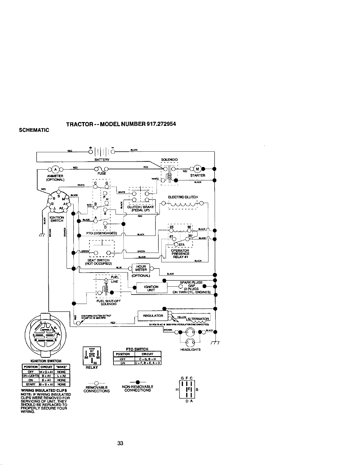
SCHEMATIC
TRACTOR -- MODEL NUMBER 917.272954
AMMETER
(OPTIONAL)
BSI
IGNmONSWITCH
WIRING INSULATED CLIPS
NOTE: IF WIRING INSULATED
CLIPS WERE REMOVED FOR
SERVICING OF UNIT, THEY
SHOULD BE REPLACED TO
PROPERLY SECURE YOUR
WIRING.
GFC
REMOVABLE NON-REMOVABLE
CONNECTIONS CONNECTIONS H B
DA
33
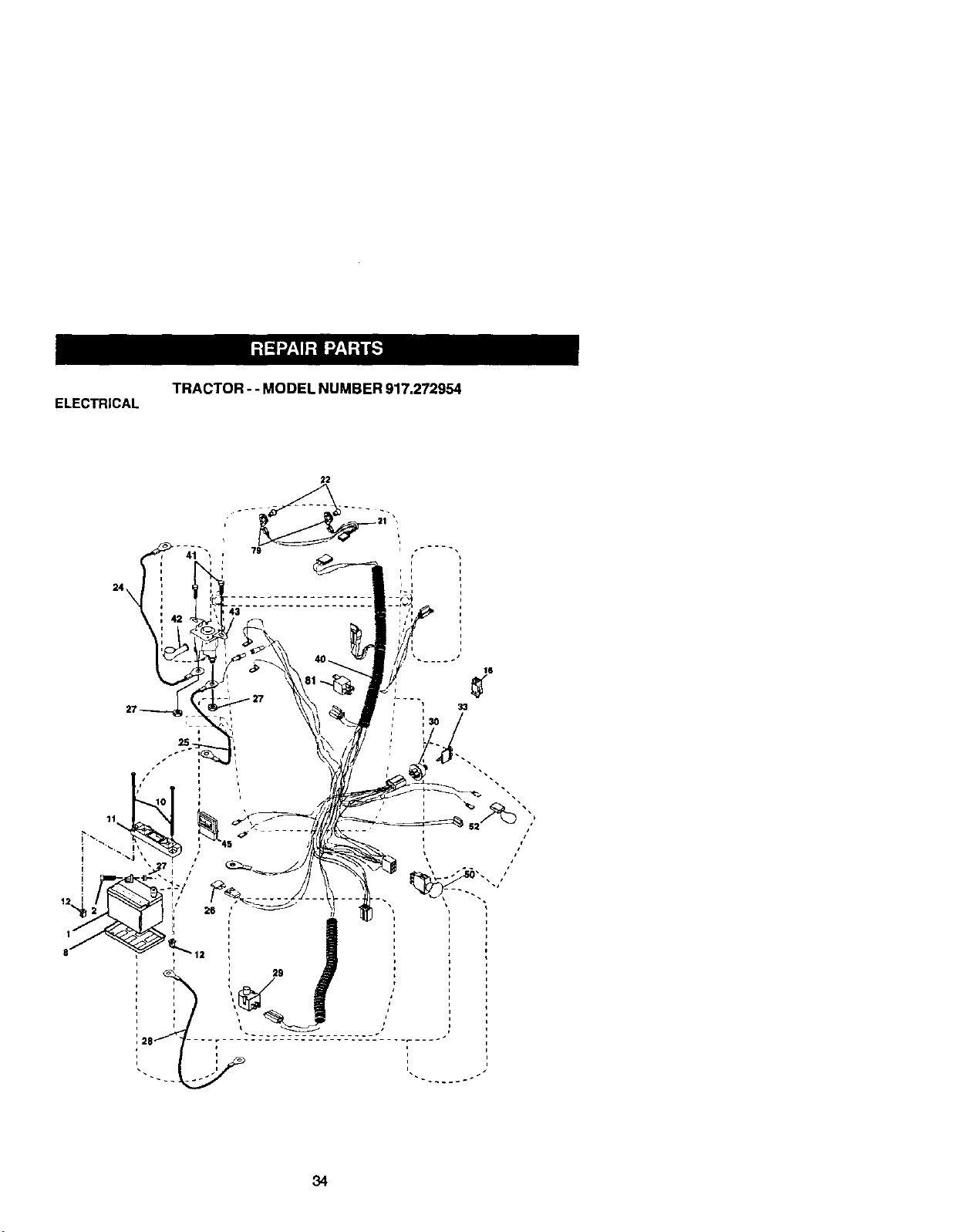
ELECTRICAL
TRACTOR - - MODEL NUMBER 917.272954
16
' 33
34

ELECTRICAL
TRACTOR - - MODEL NUMBER 917.272954
KEY PART
NO, NO. DESCRIPTION
1 144927 Battery
2 74760412 Bolt Hex Head 1/4o20 x 3/4
8 7603J Tray, Ba0ePj
10 145211 Bolt 1/4-20 x 7,5 Zinc
11 150109 Hold down Satte_ Dash Mount
12 145769 Nut Push Nylon 1/4"
16 153664 Switch Interiock Push-In
21 166184 Harness Socket Light W/4152J
22 4152,1 Bulb Light
24 4014J Cable Battery
25 146686 Cable, Battery
26 108524X Fuse
27 73510400 Nut Keps Hex 1/4-20 Uric
28 170697 Cable;Ground
29 160784 Switch, Plunger
30 175566 Switch, Ign
33 140403 Key, Ignition
40 175238 Harness Ign.
41 17720408 Screw Thd. Cut 1/4-20 x I/2
42 131563 Cover, Terrnin_
43 178861 Solenoid
45 122822X Ammeter
50 174652 Switch, PTO
52 141940 Protection Wire Loop
79 163996 Bulbholder Asrn. Incandescent
81 109748X Relay Asm.
NOTE: All component dimensions given in U.S, inches
1 inch = 25.4 mm
35
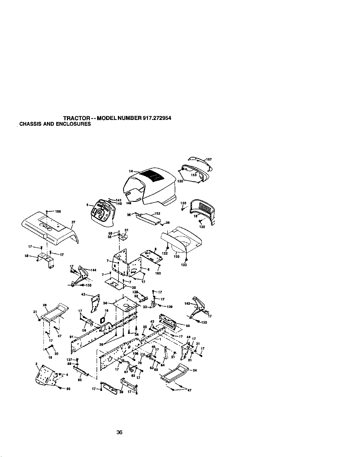
TRACTOR-- MODEL NUMBER 917.272954
•CHASSISAND ENCLOSURES
15;'
37
581_ 17
17 144 7_
2t 17
47 91 -
I 17
19
2 88
36
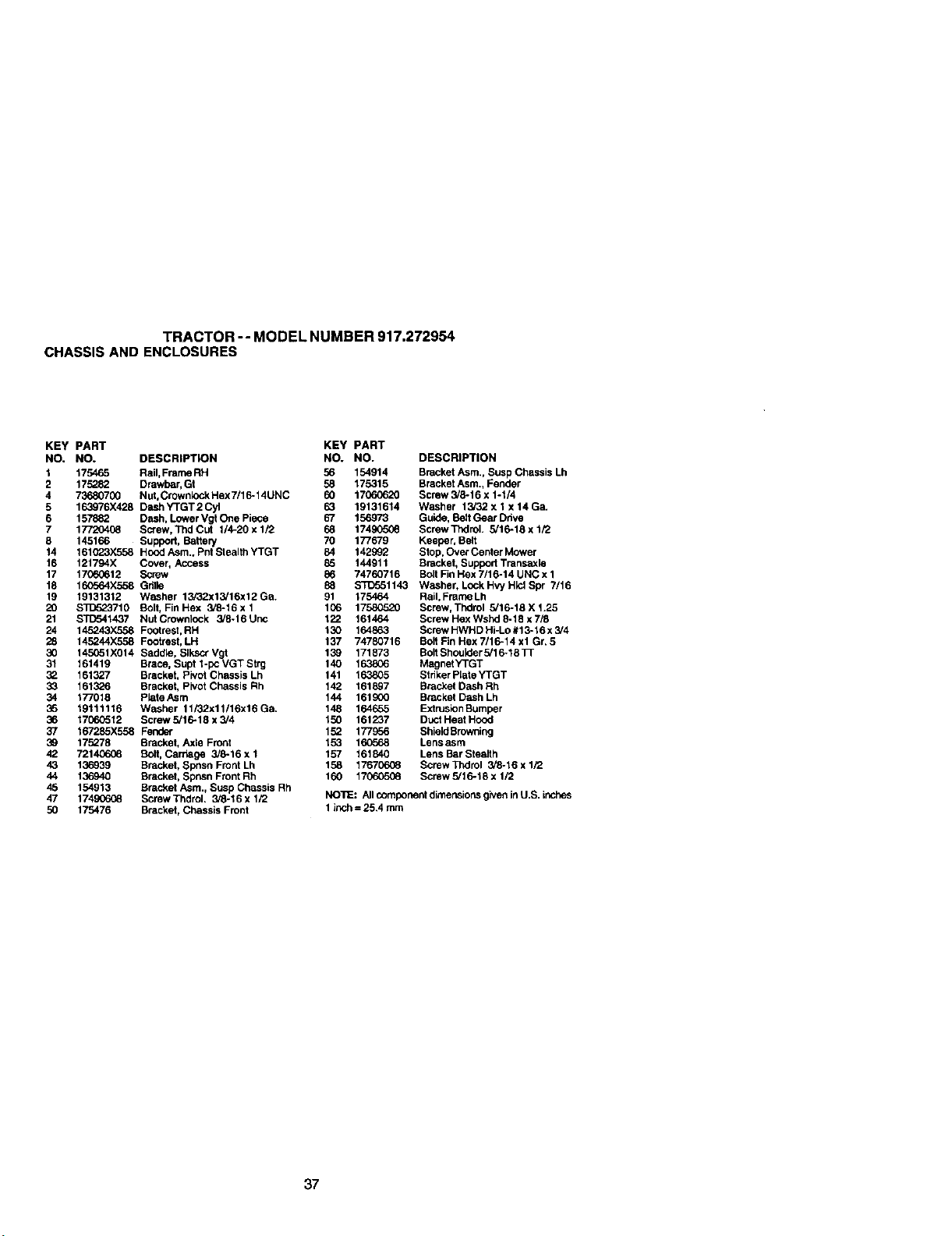
TRACTOR -- MODEL NUMBER 917.272954
CHASSIS AND ENCLOSURES
KEY PART KEY PART
NO, NO. DESCRIPTION NO. NO. DESCRIPTION
1 175465 Rail, Frame RH 56 154914 Bracket Asm., Susp Chassis Lh
2 175282 Drawbar, Gt 58 175315 Bracket Asm., Fender
4 73680700 Nut, Crownl_.k Hex 7/16-14UNC 60 17(To0620 Screw 3/6-16 x 1-1/4
5 163976X428 DashYTGT2Cyl 63 19131614 Washer 13i32xlx14Ga.
6 157882 Dash, Lower Vgt One Piece 67 156973 Guide, Belt Gear Ddve
7 17720408 Screw, T_lCut 1/4-20xl/2 68 17490508 ScrewThdroL 3/16-18xl/2
8 145166 Support, Bettei 7 70 177679 Keeper, Belt
14 161C_3X558 Hood Asm. Pnt Slealth YTGT 84 142992 Stop, Over Center Mower
16 121794X Cover, Access 85 144911 Bracket, Suppod Transaxid
17 17060612 Screw 86 74760716 BoltFin Hex 7/16-14 UNC x 1
18 160564X558 Gdlle 88 STD551143 Washer, LockHvyH_clSpr 7/16
19 19131312 Washer 13/32x13/16x12 Ga. 91 175464 Rail, Frame Lh
20 $3_523710 Bolt, FinHex 3/6-16xl 106 17580520 Screw, Thdrol 3/16-18X1.25
21 _1437 NutCrownlock 3/6-16Unc 122 161464 ScrewHexWshd8-18x7/8
24 145243X558 Footrest, RH 130 164863 ScrewHWHBHi-Lo#13-16x3,'4
28 145244X558 Footrest, LH 137 74780716 Bolt Fin Hex 7/16-14 xl Gr. 5
30 145051)(014 Saddle, SlkscrVgt 139 171873 Bo6BhouiderS/16-18Tr
31 161419 Brace, Supt l-pc VGT Btrg 140 163806 MagnetYTGT
32 161327 Bracket, Pivot Chassis Lh 141 163805 Striker PLateYTGT
33 1613_6 Bracket, Pivot Chassis Rh 142 161897 Bracket Dash Rh
34 177018 PlateAsm 144 161900 Bracket Dash Lh
35 19111116 Washer 11i32x11/16x16Ga. 148 164655 ExtrusidnBumper
36 17060512 Screw 5/16-18 x 3/4 150 161237 Duct Heat Hood
37 167285X558 Fender 152 177956 ShieidBrowning
39 175278 Bracket, Axle Front 153 160568 Lensasm
42 72140608 Bolt, Cartage 3/8-16 x 1 157 161840 Lens Bar SteaJth
43 136939 Bracket, Spnsn Front Lh 158 17670608 Screw Thdrol 3/6-16 x 1/2
44 136940 Bracket, Sposn Front Rh 160 17060506 Screw 5/16-18 x 1/2
45 154913 Bracket Asm., Susp Chassis Rh
47 174906(_ ScmwThdrol. 3/8-16x 1/2 NOTE: Altcomponent dimensionsgiveninU.S, inches
50 175476 Bracket, Chassis Front 1 inch = 25.4 mm
37
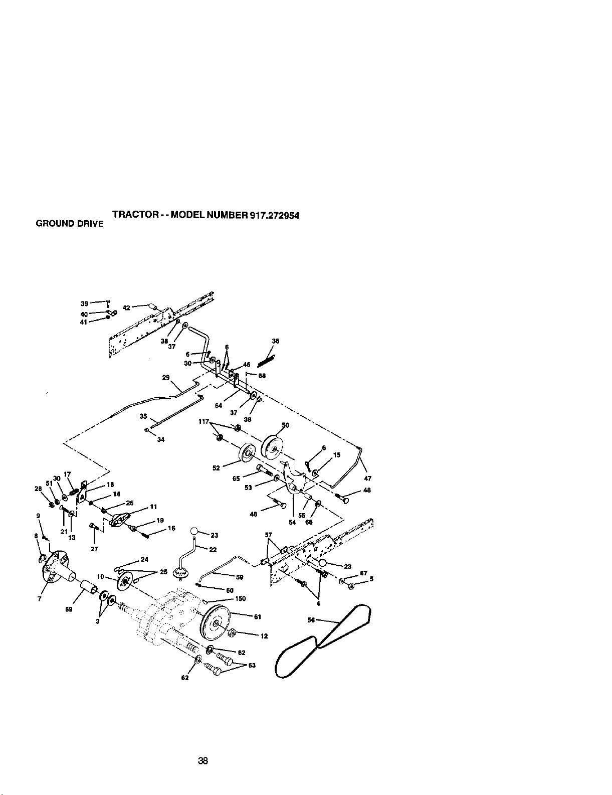
TRACTOR-- MODEL NUMBER 917.272954
GROUND DRIVE
38

TRACTOR -- MODEL NUMBER 917.272954
GROUND DRIVE
KEY PART KEY PART
NO. NO. DESCRIPTION NO. NO. DESCRIPTION
3 7552R Washer, ThrUst, Axle 38 150035 Nyliner
4 1748_.508 Screw Thdrol 5/16-18 x 3/4 39 743_1016 Screw, Fin. #10-24 x 1
5 STD541437 Nut, Crownleck 3/8-16 40 178575 Actuator, Intedock
6 STD561210 Pin, Cotter 41 73931000 Locknut #10-24
7 149176 Wheel, Hub Assembly 42 8852R Cover, Pedal
8 12000034 Klip, Ring 46 145170 Retainer, Spring
9 14(_80 _,Hub 47 135228 Clutch Rod
10 142509 Disc, Broke 48 72110612 Bolt, Corr. 3/8-16 x 1-1/2 Gr. 5
11 136927 Yoke, Brake Disc 50 131494 Pulley, Idler, Flat
12 73750800 Nutleck 1/2-20 Unf 51 ST[To41437 Nut, Crownlock 3/6-16 UNC
13 139419 Washer, Special 52 139123 Pulley, Idler, Grooved
14 138901 Bushing 53 267J Washer, Hardened
15 BTD551037 Washer 13/32x13/16 x 16 Ga. 54 161590 Clutch, Arm Assembly
16 143012 Sel, Screw 1/4-28 x 3/4 55 105706X Bearing, Idler
17 126909X Spnng 56 137153 V-Belt
18 137104 Lever, Brake 57 141756 Bracket, Shift Rod, Hi-Lo
19 136926 Cam, Brake Disc 59 122253X Shift Rod, Hi-Lo
21 23260412 Screw, Flat Head 1/4-28 x 3/4 60 122268X Sphng Clip, Connecting Link
22 633A109 Gearshift, Lever Assembty 61 137524 Pulley, Trat_axle
23 106932X Knob 52 STO551143 Washer, Lock 7/16
24 136925 Support, Puck Brake 63 74760720 Belt, Fin Hex 7/16-14 x 1-1/4
25 136923 Puck, Brake Top 64 154752 Shaft, Clutch/Brake Pedal
26 137552 Spdng, Return 65 67609 Bolt, Shoulder
27 1749_o28 Screw, Hex Wsh Thd. 66 145296 Washer, Hardenod
5/16-18 x 1-3/4 67 19131312 Washer, Flat
28 7_ Nut, Hex Jzzm 3/8-16 68 5142H Pin, Roll
29 137213 Brake, Rod 69 136327 Hub, Cover
30 19131616 Washer 13/32. xlx16Ga. 117 73900600 Nut, LockRg. 3/8-16Unc
34 71673 Cap, Plunger 150 9e58M1 Key, Woodruff
35 137648 Rod, Parking Brake
36 149412 Spring, Ddve Ground NOTE: All component dimensionsgiver1in U.S. inches
37 121749X Washer 25/32 x1-1/4 x 16 Ga. 1 inch = 25.4 mm
39
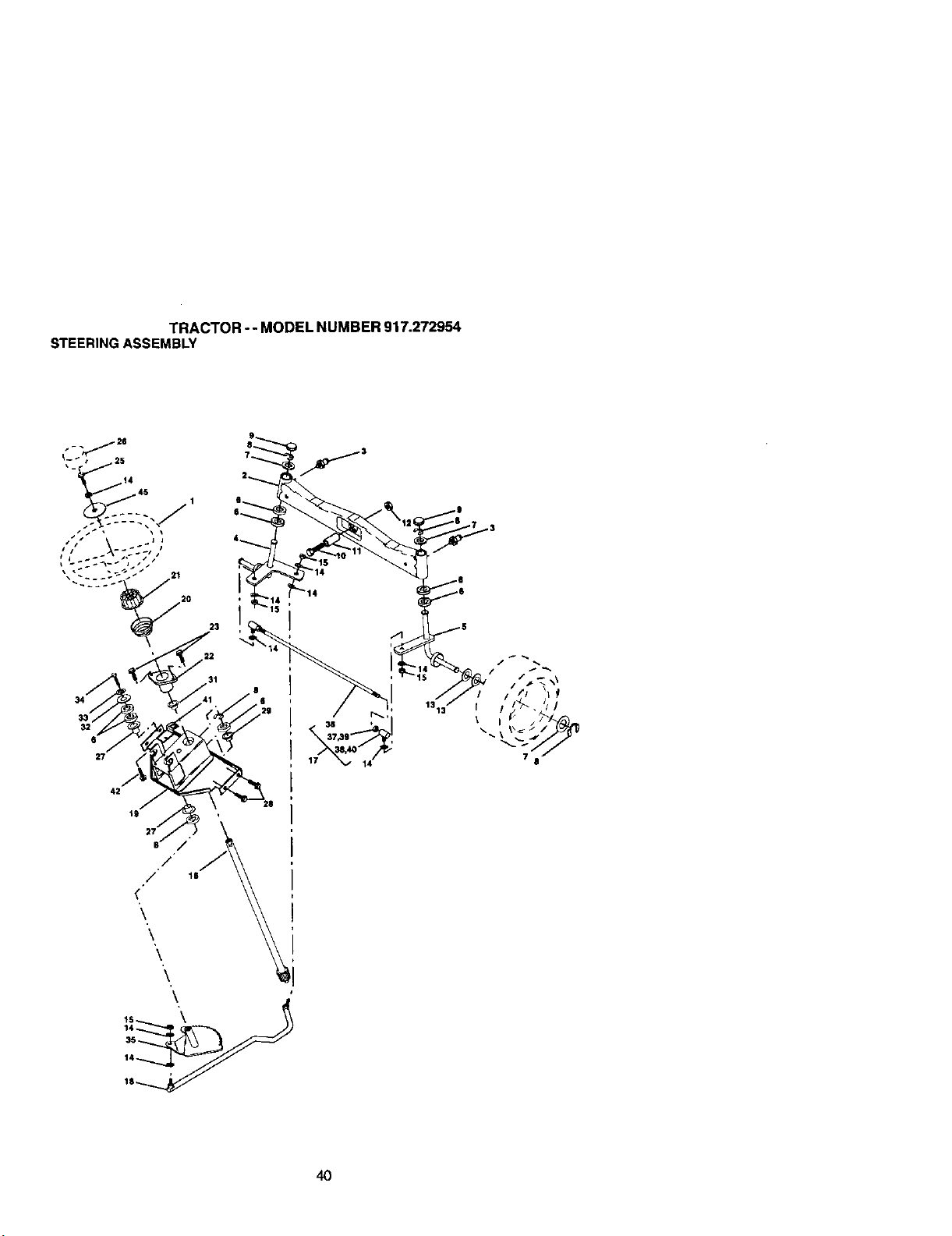
TRACTOR-- MODEL NUMBER 917.272954
STEERINGASSEMBLY
19
7"
/
18
_14
14
14
35
14
1,@
4O
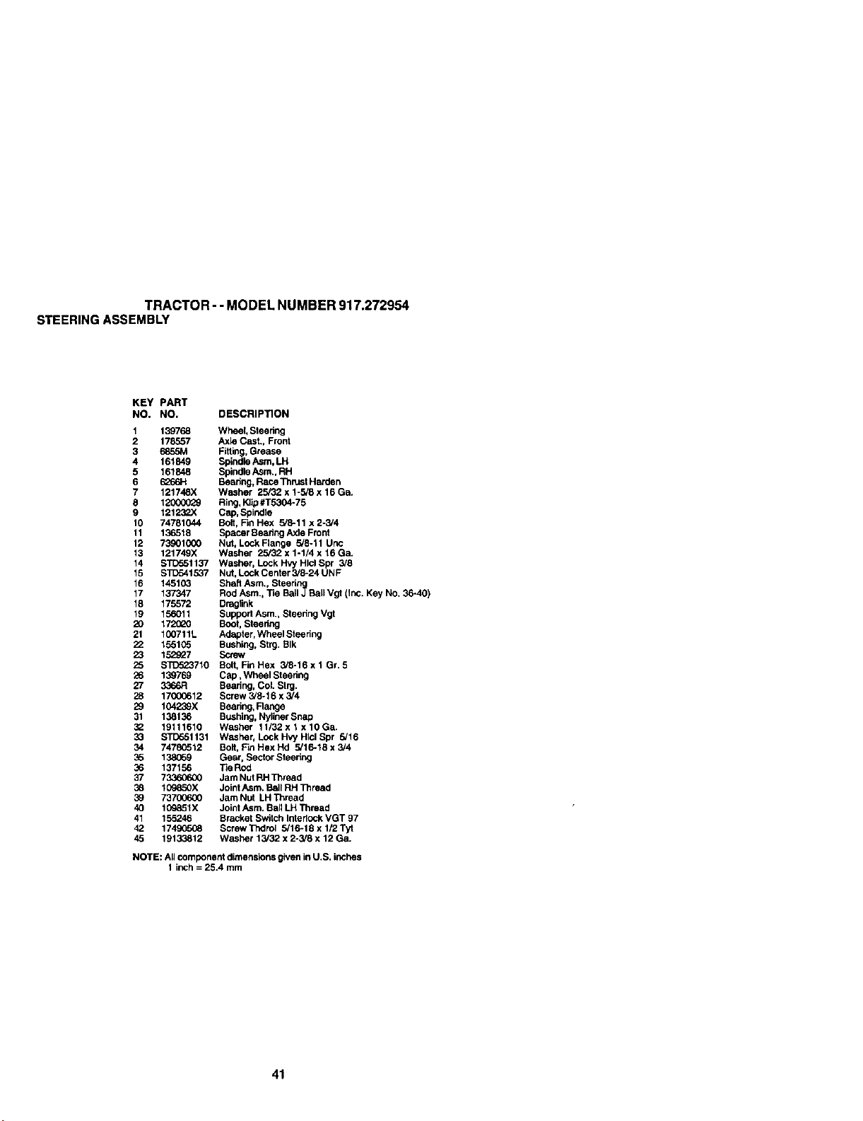
TRACTOR-- MODEL NUMBER 917.272954
STEERINGASSEMBLY
KEY PART
NO, NO. DESCRIPllON
1 139768 Wheel, Steering
2 178557 Axle Cast., Front
3 685_,t Fitting, Grease
4 161849 Spindle/_sm, LH
5 161848 Spindle Asm,, RH
6 6266H Beapng, Race Thrust Harden
7 121748X Washer 25/32 x 1-5/8 x 16 Ga.
8 12000029 Ring, Klip#T5304-75
9 12123P.X Cap, Spindle
10 74781044 BOll, Fin Hex 5,8-11 x 2-3/4
11 136518 Spacer Beadng Axle Front
12 73901000 Nut, Lock Flange 5'8-11 Unc
13 121749X Washer 25/32 x 1-1/4 x 16 Ga.
14 STD551137 Washer, Lock Hvy Hlcl Spr 3/8
15 STD541537 Nut, Lock Center 5/8-24 UN F
16 14510_ Shaft Asm., Steering
17 137347 Rod Asm., Tie Ball J Ball Vgt (inc. Key NO. 36-40)
18 175572 Draglink
19 156011 Support Asm. Steering Vgt
20 172_0 Boot, Steering
21 100711L Adapter, Wheel Steedng
22 155105 Bushing, Strg. SIk
23 152_7 Screw
25 STD523710 Bolt, Fin Hex 3/8-16 x 1 Gr. 5
26 139769 Cap, Wheel Steering
27 3366R Beadng, Col. Slrg,
28 17(X)C612 Screw 3/8-16 x 3/4
29 104259X Bearing, Range
31 138136 Bushing, Nyliner Snap
32 19111610 Washer 11/32x 1 x 10Ga.
33 STD551131 Washer, Lock Hvy Hlel Spr 5/16
34 74780512 Bolt, Fin Hex Hd 5/16-18 x 3/4
35 138G59 Gear, Sector Steering
36 137156 Tie Rod
37 73360600 Jam Nut RH Thread
38 109850X Joint Asm. Ball RH Thread
30 73700600 Jam Nut LH Thread
40 109851X Joint Asm. Bali LH Thread
41 155246 Bracket Switch InterlOCkVGT 97
42 174_K)SG8 Screw Trutrol 5/16-18 x 1/2 Tyt
45 19133812 Washer 13/32 x 2-3/8 x 12 Ga.
NOTE: All component dimensions given in U.S. inches
I inch = 25.4 mm
41
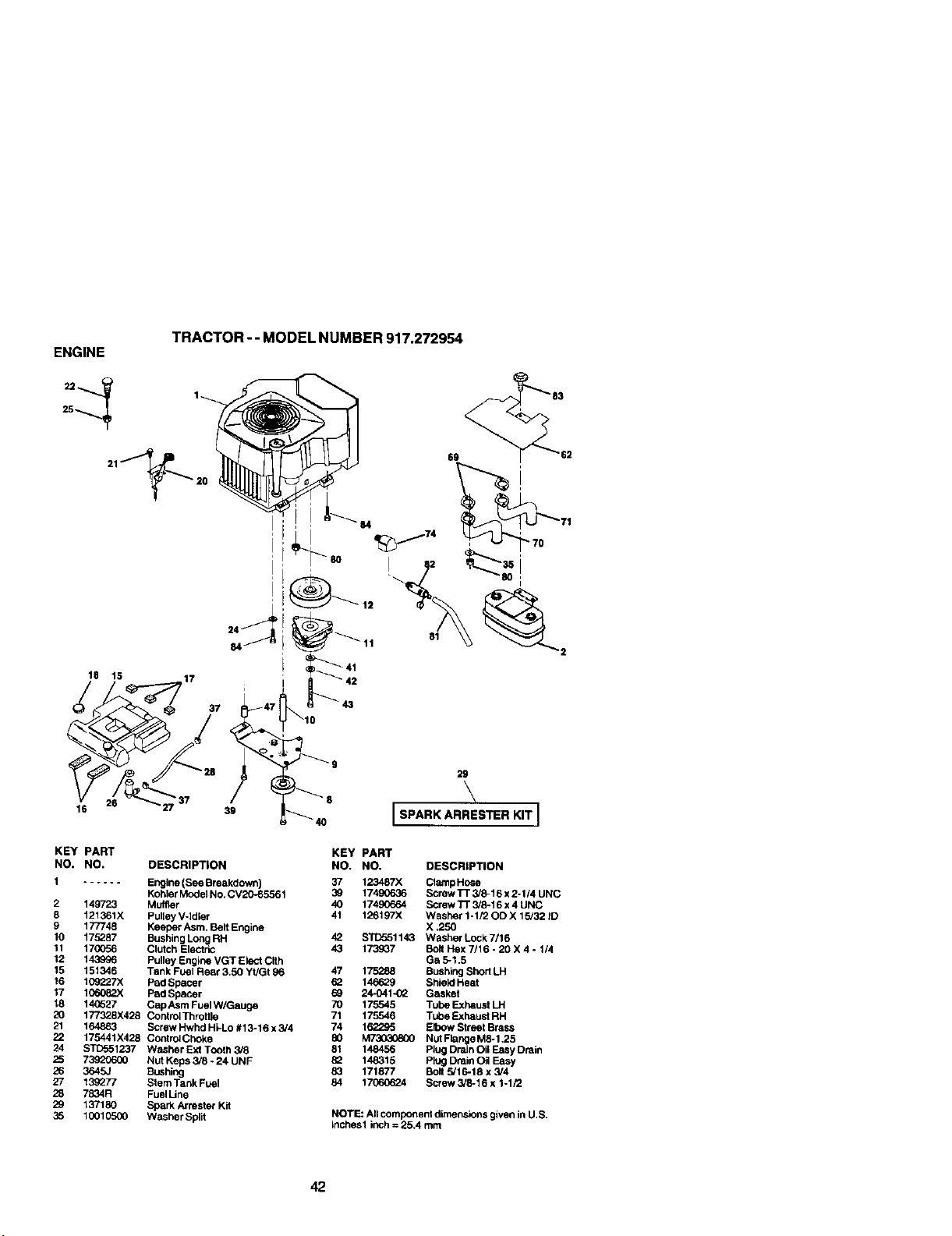
TRACTOR- - MODEL NUMBER 917.272954
ENGINE
25
18 15
16
17
37
39
81
I
I
4o
29
\
ISPARKARRESTERKITI
KEY PART
NO. NO. DESCRIPTION
1 ...... Engine(SeeBreakdown)
KohlerModelNo.CV20-65561
2 149723 Muffler
8 121361X Pulley V-Idler
9 177748 Keeper Asm. Belt Engine
10 175287 Bushing Long RH
11 17(X)56 Clutch Electric
12 143996 Pulley Engine VGT Elect Clth
15 151346 Tank Fuel Rear 3.50 Yt/Gt 96
16 t09"Z27X Pad Spacer
17 1C6082X Pad Spacer
18 14C627 Cap Asm Fuel W/Gauge
20 177328X428 Control Throttle
21 164863 Screw Hwhd Hi-Lo #13-16 x 3/4
22 175441X428 Control Choke
24 STD551237 Washer Ext Tooth 3,/8
25 73920600 Nut Keps 3/8 * 24 UNF
26 3645J BLmhing
27 139277 Stem Tank Fuel
28 7834R FuelLine
29 137180 Spark/_'rester Kit
35 10010500 Washer Split
KEY PART
NO. NO, DESCRIPTION
37 123487X ClempHose
39 17490636 Screw TT 3/8-16 x2-1/4 UNC
40 17490664 Screw ]'r 3/5.16 x4 UNC
41 126197X Weshar 1-1/20D X 15/32 ID
X ,250
42 S'i_51143 Washer Lock 7/16
43 173_37 Bolt Hex 7/16 - 20 X 4 * 1/4
Ga 5-1,5
47 175288 Bushing Short LH
82 1_ Shield Heat
24-O41-02 Gasket
70 175545 Tube Exhaust LH
71 175546 Tube Exhaust RH
74 162295 Elbow Street Brass
80 _ NutFlange M5.1,25
81 148456 Plug Drain Oil Easy Drain
82 148315 Plug Drain OR Easy
83 171877 Bolt 5/16-18 x 3/4
84 17(To_6_4 Screw 3/5.16 x 1-1/2
NOTE: All component dimensions given in U.S.
inches1 inch = 25.4 mm
42
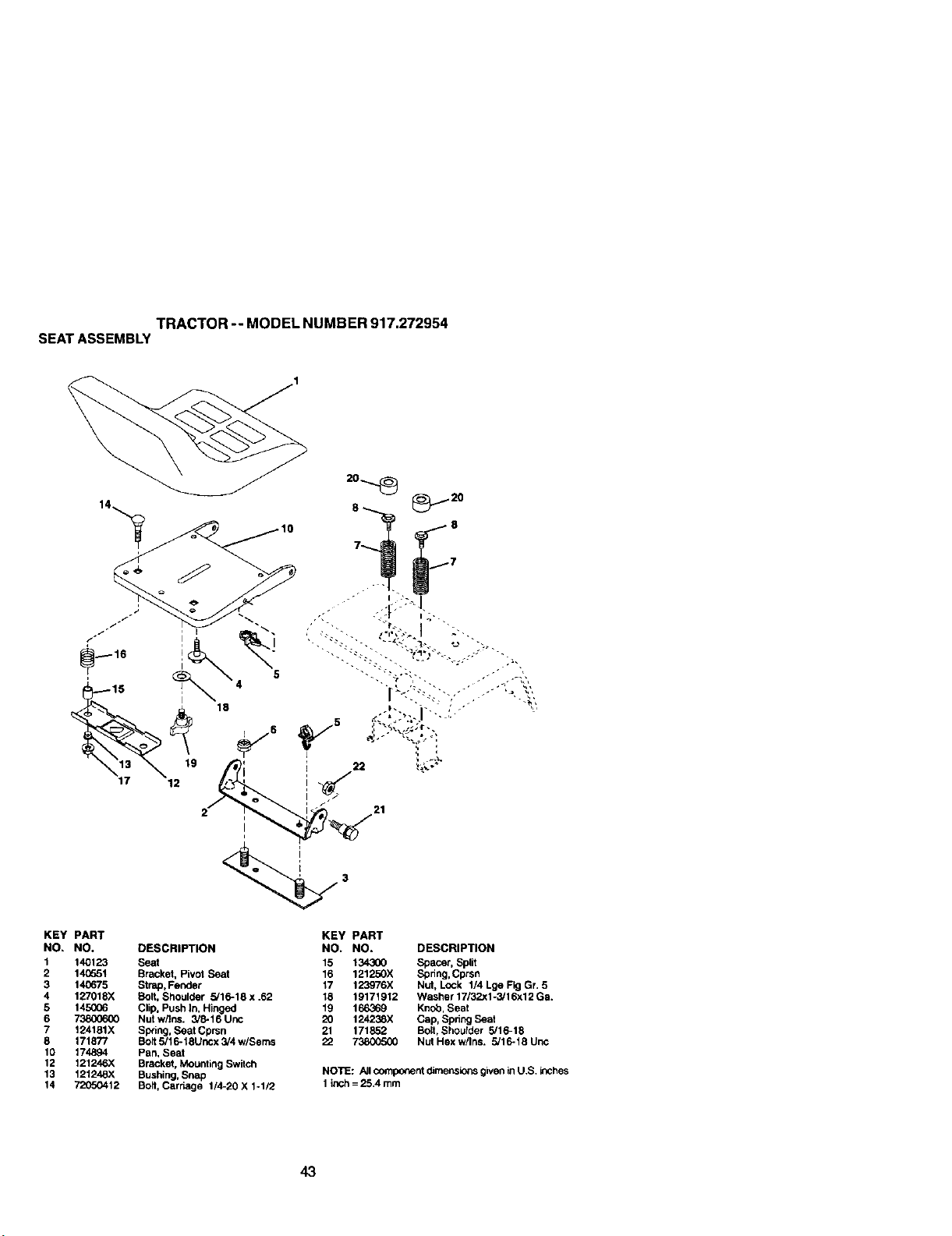
TRACTOR-- MODEL NUMBER 917.272954
SEATASSEMBLY
KEY PART
NO, NO. DESCRIPTION
1 140123 Seat
2 140651 Bracket, Pivot Seat
3 140675 Strap, Fender
4 12S/018X Bolt, Shoulder 5/18-18 x .52
5 145006 Clip, Push In, Hinged
6 73800600 Nut w/Ins. 3/8-16 Unc
7 124181X Swing, Seat Cprsn
8 171877 Bolt 5i18-18Uncx 5/4 w/seres
10 174894 Pan, Seat
12 121246X Bracket, Mounting Switch
13 121248X Bushing, Snap
14 72050412 Boit, Carr_ge 1/4-20 X %1/2
KEY PART
NO. NO. DESCRIPTION
15 134300 Spacer, Split
16 121250X Spdng,Cprsn
17 123976X Nut. Lock 1/4 Lge Fig Gr. 5
18 19171912 Washer 17/32xl-3/16x12 Ga.
19 166369 Knob, Beat
20 124238X Cap, Spring Seat
21 171852 Boit, Shoulder 5/18-18
22 73800500 Nut Hex w/Ins. 5/16-18 Unc
NOTE: All component dimensions giveninU.S. inches
1 inch= 25.4 mm
43

DECALS
TRACTOR - - MODEL NUMBER 917.272954
9
2 6 15 4
\
13
lO
16
17
_EY PARr
NO, NO.
1 172507
2 164085
3 1717(_
4 171703
5 149516
6 133644
7 163_10
8 171705
9 163_04
10 156439
11 4_OOJ
12 146047
KL=Y PART
DES(RIP'nON NO. NO.
Decal, Dash Panel 13 133179
Decal, Dash 14 160397
Decal, Hood, Craftsman, RH 15 174665
D_cal, Hoed, Craftsman, LH 16 24-113-30
Decal, Battery DNGR/PSN 17 24-113-18
ENG Asm 19 138047
Decal, Maintenance 23 1_
Decal, Fender, Side - - 138311
Decal SD, PNL
Decal, Fender, Craftsman - - 157199X428
Decal, Fender Danger - - 179476
Decal, Clutch/Brake - - 179477
Decal, V-Belt Drive Schematic
DESCRIPTION
Decal, Mower
Decal, V-Belt Schematic
Decal, Repl Parts
Decal, Engine
Decal, Engine KHLR Fan
Decal, Batte,3/
Regeclor, Taillight
Decal, Handle Lift Height
Adjust (Lift Handle)
Pad. Footrest
Manual, Owner's (Eng)
Manual, Owner's (Span)
WHEELS &TIRES
4
10
KEY PART
NO. NO. DESCRIPTION
1 59192 Cap, Valve, Tire
2 65139 Stem, Valve
3 106228X427 Rim Assembty. Front
11 1062-/7X427 Rim Assembly, Rear
4 8134H Tube, Front (Service Item
10 7154.1 Tube, Rear (Service Item Only)
5 106230X Tire, Front
9 140183 Tire. Rear
6 278H Fitting, Grease (Front 'Wheel
c_
12 6856M F_ing, Grease
7 9040H Bearing. Flange (FrontWheel
Only)
8 104757X428 Cap, Aide (Front Wheel Only)
-- 144334 Sealant, "rire (10 oz. Tube)
NOTE: All component dircer_sicnsgivenin U.S. inches
1 inch= 25.4 mm
44
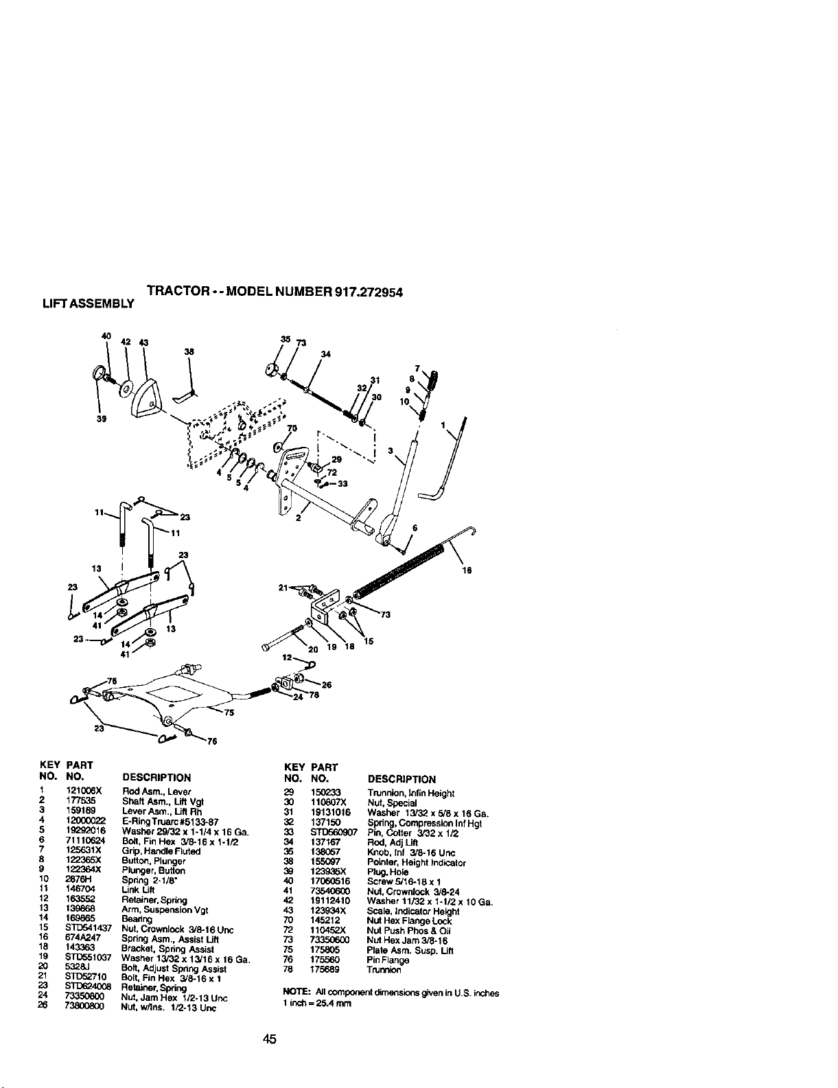
TRACTORo- MODEL NUMBER 917.272954
LIFTASSEMBLY
4O
39
42 43
38
20 19 18
16
KEY PART
NO. NO,
1 121006)(
2 1775,35
3 159189
4 1_00_22
5 19292016
6 7111_o24
7 125631X
8 1223_5X
9 122364X
10 2876H
11 146704
12 163552
13 139868
14 169865
15 STD541437
16 674A247
19 143363
19 ST0551037
20 5328J
21 STD52710
23 S'1_6240¢8
24
26 73800800
KEY PART
DESCRIPTION NO. NO. DESCRIPTION
Rod Asm., Lever 29 150_33 Trunnion, Infln Height
Shaft Asm., Lift Vgi 30 110807X Nut, Special
Lever Asm., Uft Rh 31 19131016 Washer 13/32 x 5/8 x 16 Ga.
E-Ring Truarc #5133-87 32 137150 Spring, Compression Inf Hgt
Washer29i32x1-1/4x16Ga. 33 STIT,560907 Pin, Cotter 3/32xl/2
Bolt, Fin Hex 3/8-16 x 1-1/2 34 137167 Rod, Adj Uft
Ghp,HandleFluted 35 138(;57 Knob, Inf 3/6-16 Uric
Butto¢l,Plunger 3_ 155(_7 Pointer, Height Indicator
Plunger, Button 39 123936X Plug, Hole
Spring 2-1/8" 40 17060516 Screw 5/16-16 x 1
Link Lift 41 73540600 NUt, Crownlock 3/6-24
Retainer,Sprk_ 42 19112410 W_sher 11/32 x 1-1/2 x 10 Ga.
Arm, Suspension Vgt 43 123934X Scale, Indicator Height
Beadng 70 145212 Nut Hex Flange Lock
Nut, Crownlock 3/8-16 Unc 72 110452X Nut Push Phos & Oil
Spring Asm., Assist Lift 73 733506G0 Nut Hex Jam 3/8-16
Bracket, Spring Assist 75 175805 plate Asm. Susp. Uft
W_s_',er 13i32 x 13J16 x 16 Ga. 76 1755_O pinF_ange
Bolt, Adjust Spdng Assist 78 175689 Trunnion
Bolt, Fin Hex 3/6-16 x 1
Retainer, Spring NOTE: All component d_mensio_ given in U.S. inut'_es
Nut, Jam Hex 1/2-13 Unc 1 inch==25.4 mm
Nut, w/Ins. 1/2-13 Unc
45

TRACTOR-- MODEL NUMBER 917.272954
MOWERDECK
46
49
49
34
4#
45
47
31
116
117
3 118
19
|17
46
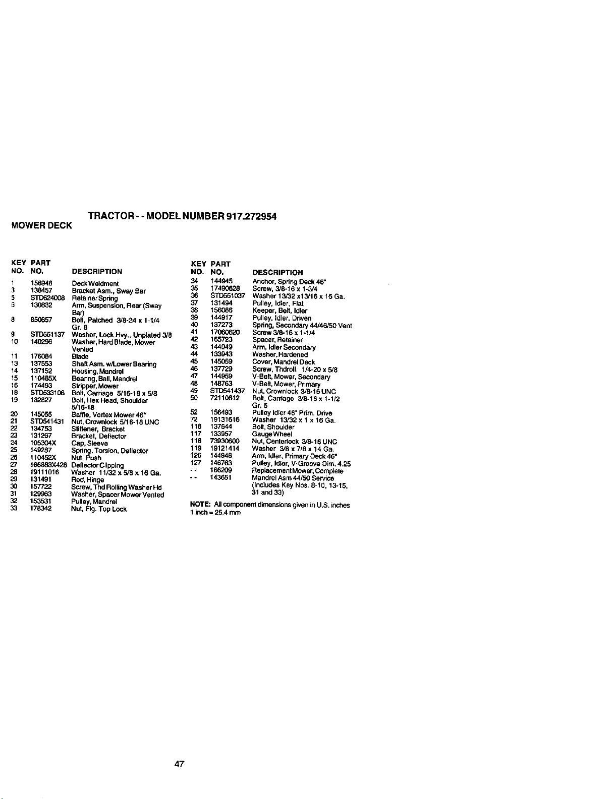
TRACTOR- - MODEL NUMBER 917.272954
MOWERDECK
KEY PART KEY PART
NO. NO. DESCRIPTION NO. NO,
1 156948 Deck Weldment 34 144945
35 17490628
3 138457 Brackut Asm., Sway BaT 36 STD5510G7
5 $1_(_4008 Retainer Spdng 37 131494
6 130832 Arm, Suspension, Rear(Sway 36 156{]86
Bar) 39 144917
8 850857 Bolt, Patched 3/8-24 x 1-I/4 40 137273
Gr, 8 41 17060620
9 STD551137 Washer, Lock Hvy., Unplated 3/8 42 165723
10 14(]_96 Washer, Hard Blade, Mower 43 144949
Vented 44 133943
11 176084 Blade 45 145_9
13 137553 Sheff Asm. w/Lower Beadng 46 137729
14 137152 Housk_g,t_/,_ndret 47 144959
15 110485X Bearing, Boll,Mandrel 48 148763
15 174493 Stripper, Mower 49 $10541437
18 STD5331C6 Bolt, Carriage 5/16-18x5/8
19 132827 Bolt,Hex Head, Shoulder 50 72110612
5/16-18 52 156493
20 145055 _affle, Vodex Mower 46" 72 19131616
21 S]lT.:yI1431 Nut, Crownlock 5/16-18UNC 116 137644
22 134753 Stiffener, Bracket 117 133957
23 131267 BracKet, Deflector 118 73930600
24 105304X Cap, Sleeve 119 19121414
25 149287 Spring, Torsion, Deflector t,26 144948
26 110452X Nut, Push 127 146763
27 166883X428 Deltector Clipping o- 166209
28 19111016 Washer 11/32 x 5/8 x 16 Ga.
29 131491 Red, Hinge -- 143651
30 157722 Screw, Thd RollingWasher Hd
31 129963 Washer, Spacer Mower Vented
32 153531 Pulley, Maedrel
33 178342 Nut, Fig. Top Lock
DESCRIPTION
Anchor, Spdng Deck 46"
Screw, 3/8-16 x I-3/4
Washer 13/32 x13/16 x 16 Ga.
Pulley, Idler, Flat
Keeper, Belt, Idler
Pulley, Idler, Driven
Sphng, Secondary 44/46/50 Vent
Borew 3/_-16 x 1-1/4
Spacer, Retainer
Arm, Idler SeCOndary
Washer, Hardened
Cover, Mandrel Deck
Screw, Thdroll. 1/4-20 x 5/8
V-Belt, Mower, Secondary
V-Belt, Mower, Primary
Nut, Crownlock 3/8-16 UNC
Bo_t,Carriage 3/8-16 x 1-1/2
Gr. 5
Pulley Idler 46" Prim. Drive
Washer 13/32 x 1 x 16 Ga.
Bolt, Shoutder
OaugeWheel
Nut, CenledoCk 3/8-16 UNC
Washer 3/8 x 7/8 x 14 Ga.
Ann, idler, Primary Deck 46"
Pulley, Idler, V-Groove Dim. 4.25
Re placement Mower, Complete
Mandrel Asm 44/50 Service
(Includes Key Nos. 8-19. 13-15,
31 and 33)
NOTE: All component dimensions giveninU.S. inches
1 inch ==25.4 mm
47
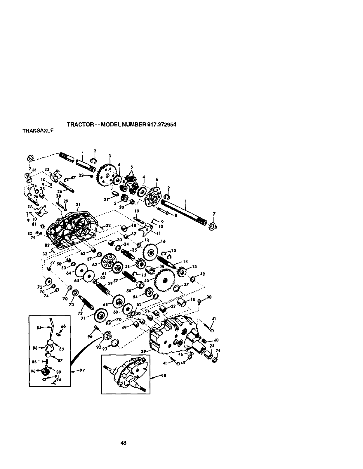
TRANSAXLE
TRACTOR - - MODEL NUMBER 917.272954
| 2
6
2
73
72
48
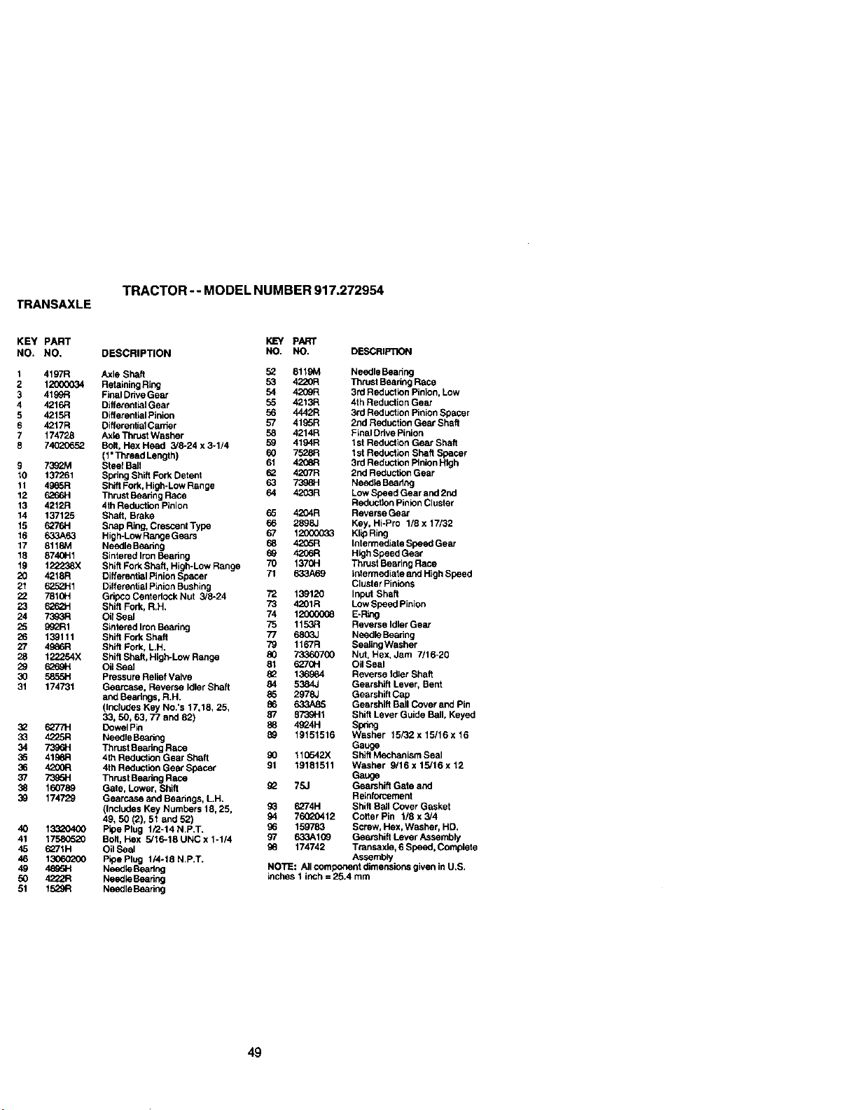
TRANSAXLE
TRACTOR -- MODEL NUMBER 917.272954
KEY PART KEY pART
NO. NO, DESCRIPTION NO. NO. DESCRIFnON
t 4197R
2 12OOO034
3 4199R
4 4216R
5 4215R
6 4217R
7 174728
8 74O2O652
9 7392M
10 137261
11 4985R
12 6=_o6H
13 4212R
14 137125
15 6276H
16 633A63
17 8118M
18 8740H1
19 122238X
20 4218R
21 62521
22 781CH
23 6262H
24
25 99_R1
26 139111
27 49e6R
28 122254X
29 6269H
30 5855H
31 174731
32 6277H
33 4225R
34 7396H
35 419_:1
36 4200R
37 73_5H
38 160789
39 174729
4O 133_O400
41 17580520
45 6271H
46 130602OO
49 4895H
50 4222R
51 t529R
Axle Shaft 52 8119M Needle Bearing
Retaining Ring 53 4220R Thrust Beadng Race
FIll Drive Gear 54 4209R 3/d Reduction Pinion,Low
Differential Gear 55 4213R 4th Reduction Gear
Differential Pinion 56 4442R 3rd ReducUon PinionSpacer
Differential Carder 57 4195R 2rid Reduction Gear Shaft
AxIO Thrust Washar 58 4214R Final Ddve Pinion
Bolt, Hex Head 3/6-24 x 3-1/4 59 4194R I st Reduction Gear Shaft
(1"Thread Length) 60 7528R I st Reduction Shaft Spacer
Steel Bell 61 4208R 3rd Reduction Pinion High
Spring Shift Fork Detent 62 4207R 2nd Reduction Gear
Shift Fork, High-Low Range 63 7398H Needle Beadng
Thrust Bearing Race 64 4203R LowSpeed Gear and 2nd
4th Reduction Pinion Reducfton Pinion Cluster
Shaft, Brake 65 4204R Reverse Gear
Snap Ring, Crescent Type 66 2898J Key, Hi-Pro 1/8 x 17/32
High-Low Range Ge_s 67 12000033 KlipRing
Needle Beadng 58 42G6R Intarmediate Speed Gear
Sintered Iron Beadng 69 4206R High Speed Gear
Sh_ftFork Shaft, High-Low Range 70 1370H Thrust Bearing Race
Different_alPinion Spacer 71 633A69 tatarmediata and High Speed
Differential Pinion Bushing Cluster Pinions
Gdpeo Centadock Nut 3/8-24 72 139120 Input Shaft
Shift Fork, R.H. 73 4201R Low Speed Pinion
OilSeal 74 12000_8 E-RIOg
Sintared Iron Beadng 75 1153R Reverse Idler Gear
Shift Fork Shaft 77 6803J Needle Bearing
Shift Fork, L.H. 79 1167R SealingWasher
Shift Shaft, High-Low Range 80 73360700 Nut, Hex, Jam 7/16-20
OilSeal 81 6270H Oil Seal
Pressure Relief Valve 82 136984 Reverse Idler Shaft
Gearcase, Reverse Idler Shaft 84 5384J Gearshift Lever, Bent
and Bearings, R.H. 85 2978J Gearshift Cap
(Includes Key No.'s 17,18, 25, 86 633A85 Gearshift Ball Cover and Pin
33, 50, 63, 77 and 82) 87 8739H1 Shift Lever Guide Bell, Keyed
Dowel Pin 88 4924H Spdng
NeedleBeadng 89 19151516 Washer 15/32 x 15/16 x 16
Thrust Reariog Race Gauge
4th Reduction Gear Shaft 90 110542X Shift M_hanism Seal
4th Reducfton Gear Spacer 91 19181511 Washer 9/16 x 15/16x 12
Thrust Bearing Race Gauge
Gate, Lower, Shift _2 75J Gearshift Gate and
Gearcase and Bearings, LH. Reinforcement
(Includes Key Numbers 18, 25, gG 6274H Shift Ball Cover Gasket
49, 50 (2), 51 and 52) 94 76020412 Cotter Pin 1/8 x 3/4
Pipe Plug 1/2-14 N.P.T. 96 159783 Screw, Hex, Washer, HD.
Bolt, Hex 5/16-18 UNC x 1-1/4 97 633A1G9 Gearshift Lever Assembly
Oil Seal 96 174742 Transaxle, 6 Speed, Complete
P_oePlug 1/4-18 N.P.T. Assembly
Needio Beadng NOTE: Altcomponent dimensions given in U.S.
Needio Beadng inches 1 inch = 25.4 mrn
NeedleBeadng
49
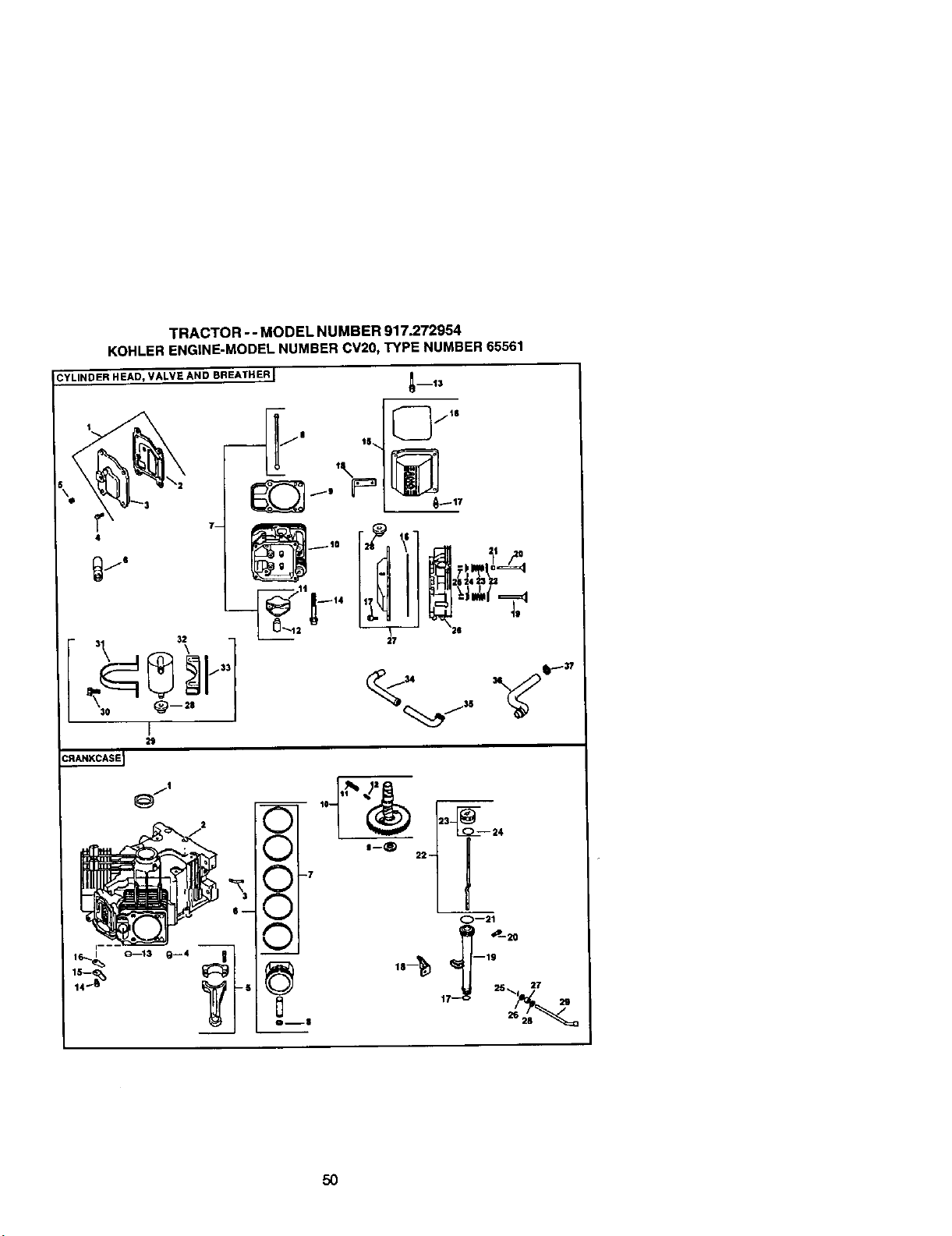
TRACTOR -- MODEL NUMBER 917.272954
KOHLERENGINE-MODELNUMBERCV20, TYPENUMBER65561
CYLINDER HEAD, VALVE AND BREATHER I
N 15,_,
,\
m'f3
[_jls
_17
4
7-
29
50

TRACTOR -- MODEL NUMBER 917.272954
KOHLER ENGINE-MODELNUMBERCV20, TYPE NUMBER65561
HEADNALVE/B REATHER
CRANKCASE
KEY PART KEY PART
NO. NO. DESCRIPTION NO, NO. DESCRIPTION
1 24-033-03-S Kit, breather cover w/ 1 24-032-01 -S Seal, oil front
gasket (Includes 2,3) 2 Crankcase
2 24-041-23-S Gasket, breather (USE: Miniblock 24 78205)
3 24-096-59-S Cover, breather 3 24-294-13-S Fittln
4 M-645020 Screw, hex. flange 4 12-380-17-S Pin, _owel locating (6)
M6xl.0X20 (4) 5 24-067-13-S Connecting Rod (Std.) (2)
5 X-75-23-S Plug, allen hal. I/8" 24-067-14-S Connecfln_. Rod (.25) (2)
6 25-351-01-S Lifter, valve (4) 6 24-874-01-S Piston w/Ring Set (Std.) (2)
7 24-755-66-S Kit, valve train (Includes (Includes 7,8)
8,11,12) 24-874-02-S Piston w/Ring Set 1,251121
8 24-411-05-S Rod, push (4) 24-874-03-S Piston w/Ring Set ,50 2
9 24-041-08-S Gasket, cylinder head (2) 24-874-14-S Piston w/ring set 4.08)
tO 24-318-12-S Head assembly, #2 cylinder 7 24-108-01-S Ring Set (Std.) (2)
11 25-186-01-S Arm, rocker 4) 24-108-02-S Ring Set (.25) (2)
12 24-599-01-S Pvot, rocker arm 4) 24-108-03-S Ring Set (.50) (2)
13 M640034-S Screw, hax. flange 8 24-018-01 -S Retainer, piston pin (4)
M6x1.0x34 (4) 9 12-422-09-S Shim, camshaft (A.R.)
14 12-086-16-S Screw, hex. flange 12-422-13-S Shim, camshaft (A.R.)
M10x1.5xg0 (8) 12-422-07-S Shim, camshaft (A).R.
15 24-755-7-S Kit, valve cover - plain 12-422-06-S Shim, camshaft 4A.R.)
12-422-10-S Shim, camshaft(Includes 16,17)
16 24-153-16-S O-Ring 12-422-11-S Shim, camshaft (A.R.)
17 24-086-32-S Screw, shoulder (4) 12-422-12-S Shim, camshaft (A.R)
18 24-445-01-S Strap, lifting 10 24-010-06-S Camshaft (Includes 11,12)
19 24-016-01-S Valve, exhaust (Std.) (2) 11 24-089-35-S Spring acr (Heavy)
24-016-02-S Valve, exhaust 4.25) (2) 12 24-089-34-S Spring act (tight)
20 24-017-01-S Valve, Intake (Std.) 42 13 52-139-09-S Plug, cup
24-017-02-S Valve, intake (.25) (2) 14 M-545010-S Screw, hex. flange
21 24-032-05-S Seal, valve stem (2) M5x0.Sxl0 (2)
22 235011-S Retainer, spring 44) 15 24-018-04-S Retainer, reed (2)
23 24-089-02-S Spring, valve (4) 16 24-402-05-S Reed, breather 42)
24 12-173-01-S Cap, valve spring 44) 17 12-153-01-S O-Ring, lower oil flEItube
25 12-755-03-S Kit, retainer (4) 18 24-126-19-S Bracket, oil flFI tube
26 24-318-11-S Head assembly, #1 cylinder 19 12-123-04-S Tube, oil fill
27 24-755-76-S Kit, valve cover - breaker 20 M-545016-S Screw, hex. flange
(incL 16,17,28) M5xO.8x16
28 25-313-02-S Grommet, rubber 21 12-153-02-S O-Ring, upper oil fl_l tube
29 24-755-57-S Kit, breather separator 22 24-038-04-S Dipstick assembly (Includes
(Includes 28,30-33) 22 23)
30 M-545016-S Screw, hex. flange 23 24-755-46-S Kit, oit fill cap (includes 23)
M5x0,8x16 42) 24 12-153-03-S O-Rin_, dipstick
31 24-445-02-S Strap, breather 25 12-380-04-S Pin h=tch
32 24-126-44-S Bracket, breather 26 M-631005-S Washer, pla n 6 mm
separator 27 12-032-01-S Seal, governor cross shaft
33 24-112-12-S Spacer 28 X-25-102-S Washer, plain I/4"
34 24-294-06-S Fitting 29 24-144-01-S ShaR, governor cross
35 24-32E-t3-S Hose, breather
36 24-326-14-S Hose, breather
37 X-426-9-S Clamp, hose (2)
51
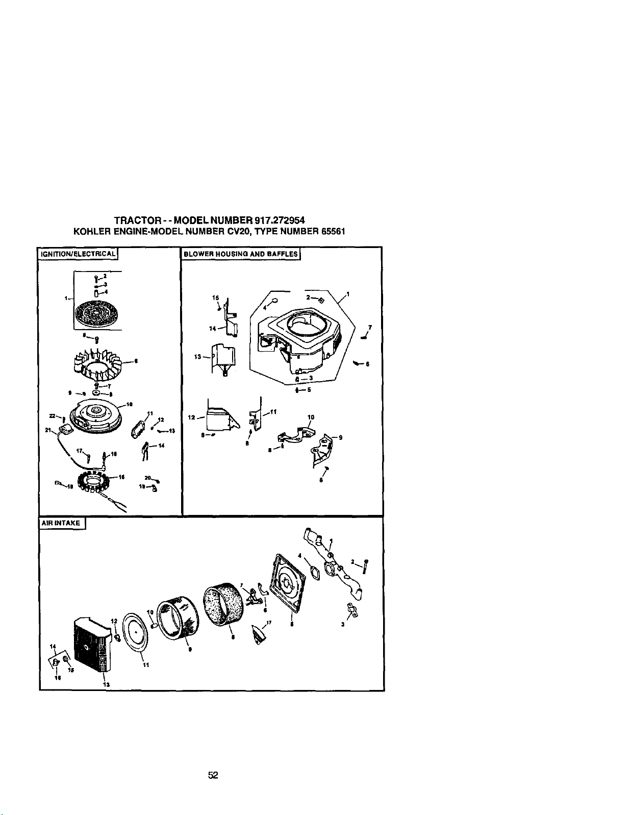
TRACTOR - - MODEL NUMBER 917.272954
KOHLER ENGINE-MODEL NUMBER CV2O, TYPE NUMBER 65561
IGNITION/FLECTRICAL I BLOWER HOUSING AND BAFFLES I
AIR iNTAKE J
3
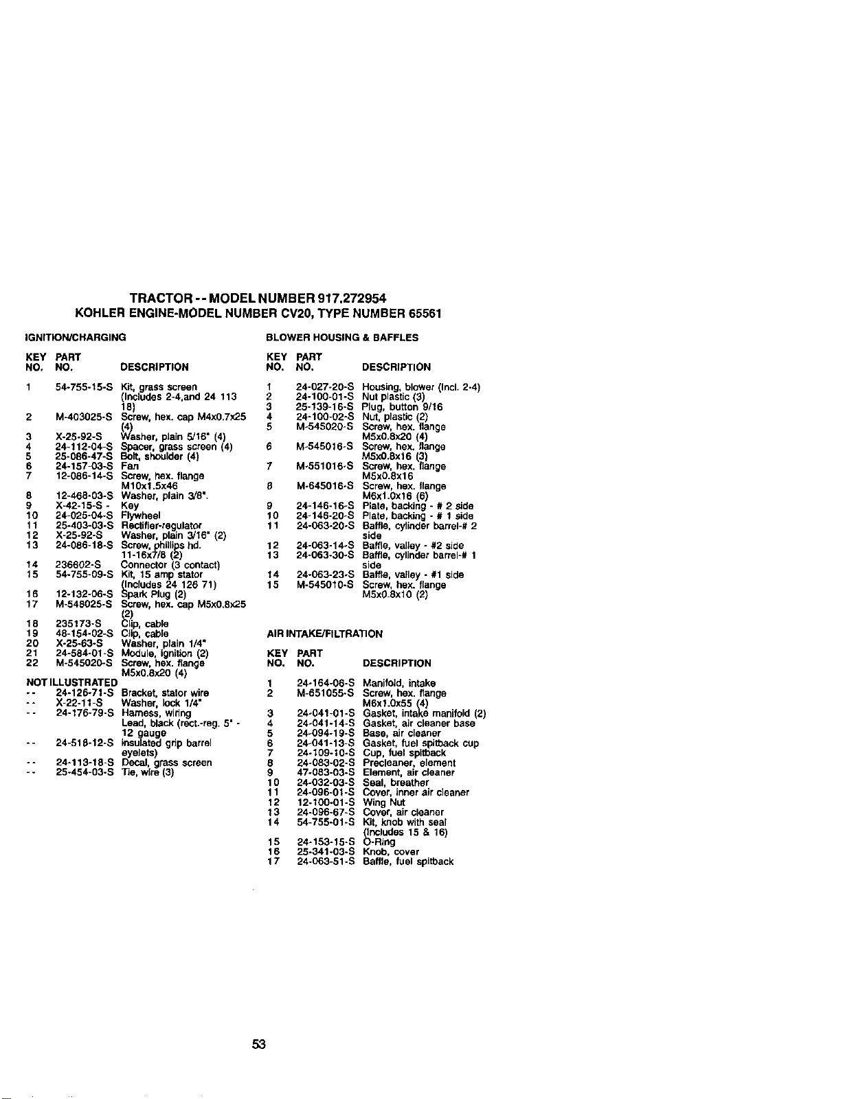
TRACTOR -- MODEL NUMBER 917,272954
KOHLER ENGINE-MODELNUMBERCV20,TYPE NUMBER65561
IGNITION/CHARGING BLOWER HOUSING & BAFFLES
KEY PART KEY PART
NO, NO. DESCRIPTION NO. NO. DESCRIPTION
1 54-755-15-S Kit, grass screen
(Includes 2-4,and 24 113
18)
2 M-403025-S Screw, bax. cap M4x0.7x25
3 X-25-92-S er, plain 5/16" (4)
4 24-112-04-S Spacer grass screen (4)
5 25-086-47-S Bolt, shoulder (4
6 24-157-03-S Fan
7 12-086-14-S Screw, flex. flange
M10xl.5x46
8 12-468-03-S Washer, plain 3/8".
9 X-42-15-S - Key
10 24-025-04-S Flywheel
11 25-403-03-S Reetifler-regulator
12 X-25-92-S Washer, plain 3/16" (2)
13 24-086-18-S Screw, hilli shd.
fff6x 8
14 236602-S Connector 13 contact)
15 54-755-09-S Kit, 15 amp stator
(includes 24 126 71)
16 12-132-06-S Spark Plug (2)
17 M-548025-S Screw, hox. cap M5x0.Ex25
18 235173-S lip, cable
19 48-154-02-S CJip, cable
20 X-25-63-S Washer, plain 1/4"
21 24-584-01-S Module, ignition (2)
22 M-545020-S Screw, hox. flange
M5x0.8x20 (4)
NOT ILLUSTRATED
-- 24-126-71-S Bracket, stator wire
-- X-22-11-S Washer, lock 1/4"
- 24-176-79-S Harness, wiring
Lead, black (rect.-reg. 5"
12 gauge
-- 24-518-12-S _nsulated grip barrel
eyelets)
-- 24-113-18-S Decal, grass screen
- - 25-454-03-S Tie, wire (3)
1
2
3
4
5
g
lO
11
12
13
14
15
24-027-20-S Housing, blower (Incl. 2-4)
24-100-01-S Nut plastic (3)
25-139-16-S Plug, button 9/16
24-100°02-S Nut, plastic 2)
Mo545020oS Screw, hex. ange
M5x0.8x2O 4)
M-545016÷S Screw, bax. ange
M5x0.8x16 (3)
M-551016-S Screw, hex. flange
M5x0.8x16
M-645016-B Screw, hex. flange
M6xl.Oxf 6 (6)
24-146-16-S Plate, backing - # 2 side
24-146-20oS Plate, backing - # I side
24-063°20-S Baffle, cylinder barrel-# 2
side
24-063-14°S Baffle, valley - #2 side
24°063-30*S Baffle, cylinder barrel-# 1
side
24-063-23-S Baffle, valley - #1 side
M-545010-S Screw, hex. flange
M5x0 8x10 (2)
AIR INTAKE/FILTRATION
KEY PART
NO. NO. DESCRIPTION
1 24°164-06-S Manifold. intake
2 M-651055-S Screw. hex. flange
MExl.0x55 (4)
3 24-041-01-S Gasket, intake manifold(2)
4 24-041-14-S Gasket, air cleaner base
5 24-094-19-S Base. air cleaner
6 24-041-13-S Gasket. fuel spitbackcup
7 24-109-10-S Cup. fuel spitback
8 24-083-02°S Precleaner. element
9 47-083-03-S Element, air cleaner
10 24-032-03°S Seal. breather
11 24-096-01-S Cover, inner air cleaner
12 12-100-01-S Wing Nut
13 24-096-67-S Cover. air cleaner
14 54-755-01-S Kit, knobwith seal
includes 15 & 16)
15 24-153-15-B _-RIng
16 25-341-03-S Knob. cover
17 24-063-51-B Baffle. fuel spitback
53
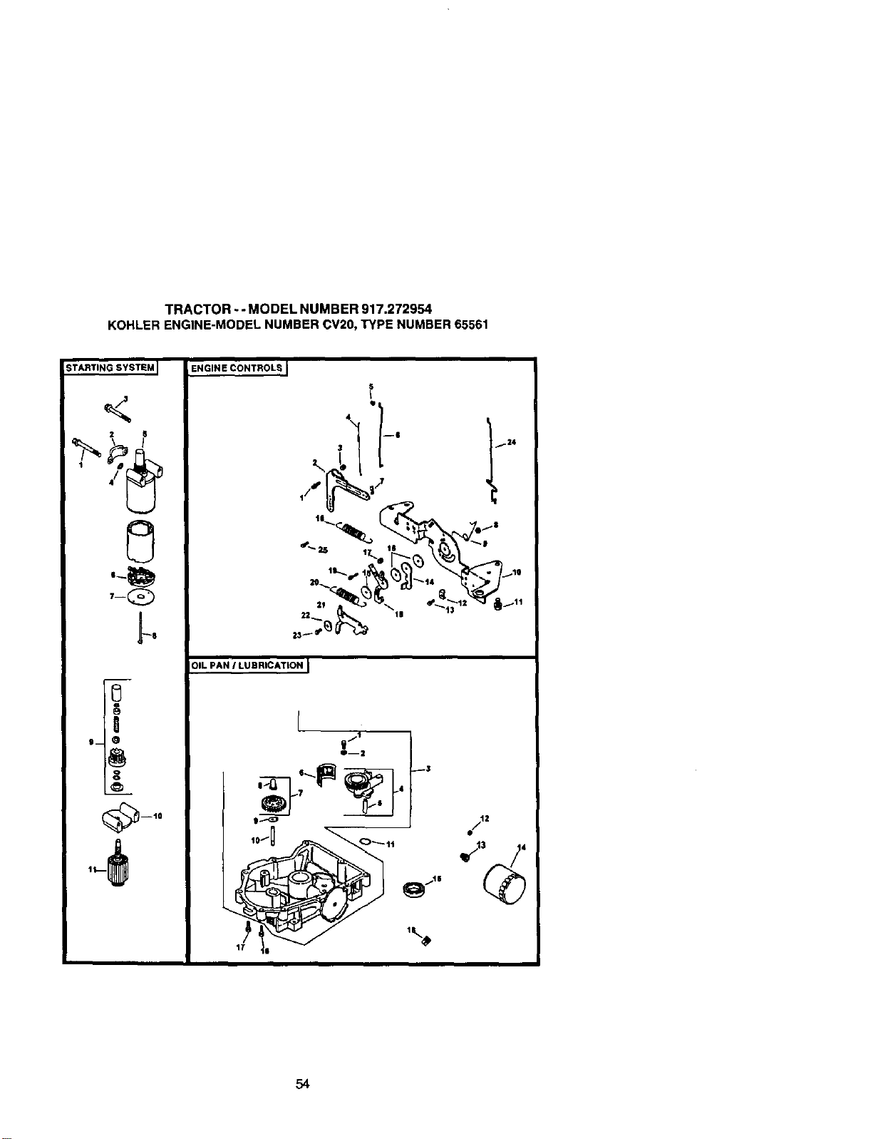
TRACTOR- - MODEL NUMBER 917.272954
KOHLER ENGINE-MODELNUMBERCV20, TYPENUMBER65561
STARTING SYSTEM I
2 6
7-Q
_8
0
!
g_ 0
mlO
31L PAN / LUBRICATION I
r
10__ 11
'%
g/12
54
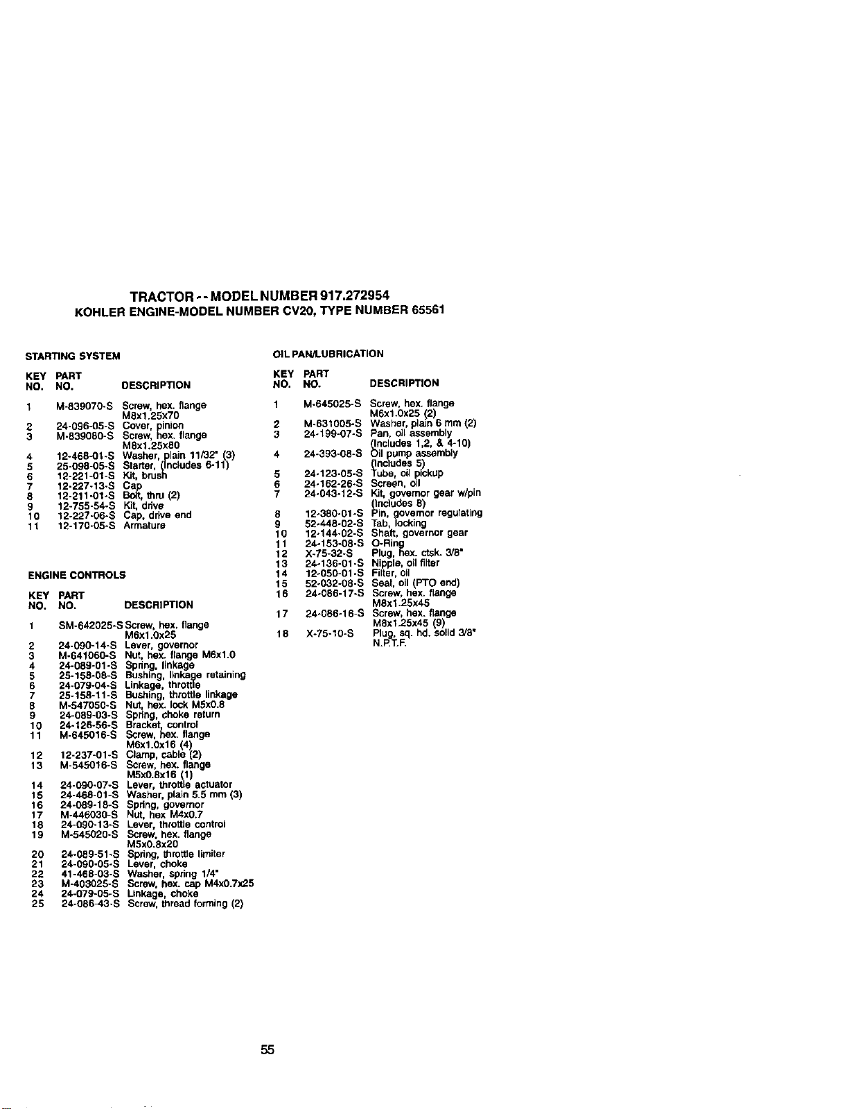
TRACTOR - - MODEL NUMBER 917.272954
KOHLERENGINE-MODELNUMBERCV20,TYPE NUMBER65561
STARING SYSTEM
KEY PART
NO. NO.
1 M-839070-S
2 24-096-05-S
3 M-839080-5
4 12-468-01-S
5 25o098-05-S
6 12-221-01-S
7 12-227-13-5
8 12-211-01-S
9 12-755-54-S
10 12-227-06-S
11 12-170-05-S
OIL PAN/LUBRICATION
KEY PART
DESCRIPTION NO. NO. DESCRIPTION
ENGINE CONTROLS
Screw, hex, flange
M8x1.25x70
Cover. inion
Screw, Rex, flange
M8xl.25xS0
Washer, plain 11/32" 3)
Starter, (includes 6-11 )
Kit, brush
_t, thru (2)
Kit, ddve
Cap, drive end
Armature
KEY PART
NO. NO, DESCRIPTION
1 SM-642025-S Screw, hex. flange
M6x1.0x25
2 24-090-14-S Lever, governor
3 M-641060-S Nut, hex. flange M6xl.0
4 24-089-01-S Spring, linkage
5 25-158-08-S Bushing, l_nkaagee retaining
6 24-079-04-S Linkage throttle
7 25-158-11-S Bushing, throttle nkage
8 M-547050-S Nut, hex. lock MSx0.8
9 24-089-03-S Spring, choke return
10 24-126-56-S Bracket, control
11 M-645016-S Screw, hex. flange
M6xl.0x16 (4)
12 12-237-01-S Clamp, cable (2)
13 M-545016-S Screw, hex. flange
M5x0.Sxl 6(1)
14 24-090-07-S Lever, throffie actuator
15 24-468-01-S Washer, plain 5.5 mm (3)
16 24-089-18-S Spdng, governor
17 M-446030-S Nut, hex M4x0.7
18 24-090-13-S Lever, throffie control
19 M-545020-S Screw, hex. flange
M5x0.8x20
20 24-089-51-S Spdng, throffie lirniter
21 24-090-05-S Lever, choke
22 41-468-03-S Washer, spdng 1/4"
23 M-403025-S Screw, hex. cap M4x0.7x25
24 24-079-05-S Linkage, choke
25 24-086-43-S Screw, _read forming (2)
1 M-645025-S Screw, hex. flange
M6x1.0x25 (2)
2 M-631005-S Washer, plain 6 mm (2)
3 24-199-07-S Pan, oil assembly
(Includes 1,2, & 4-10)
4 24.393-08-S Oil ump assembly
(inc_u_des51
5 24-123-05-S Tube, oil pickup
6 24-162-26oS Screen, oil
7 24-043-12-S Kit, governorgear w/pin
(IncludesB)
8 12-380-01-S ;-'in, g¢ovemor regulating
9 52-448-02-S Tab, locking
10 12o144-02-S Shaft, governor gear
11 24.153-08-S O-Ring
12 X-75-32-S Plug, Sex. ctsk.3/8"
13 24.136-01-S Nipple, oil filter
14 12-050-01-S Filter,oil
15 52-032-08-S Seal, oil (PTO end)
16 24-086-17-S Screw, hex. flange
M8x1.25x45
17 24-086-16-S Screw, hex. flange
MSxl.25x45 (9)
18 X-75-10-S Plug, sq. hd. solid3/8"
N.P.T.F.
55
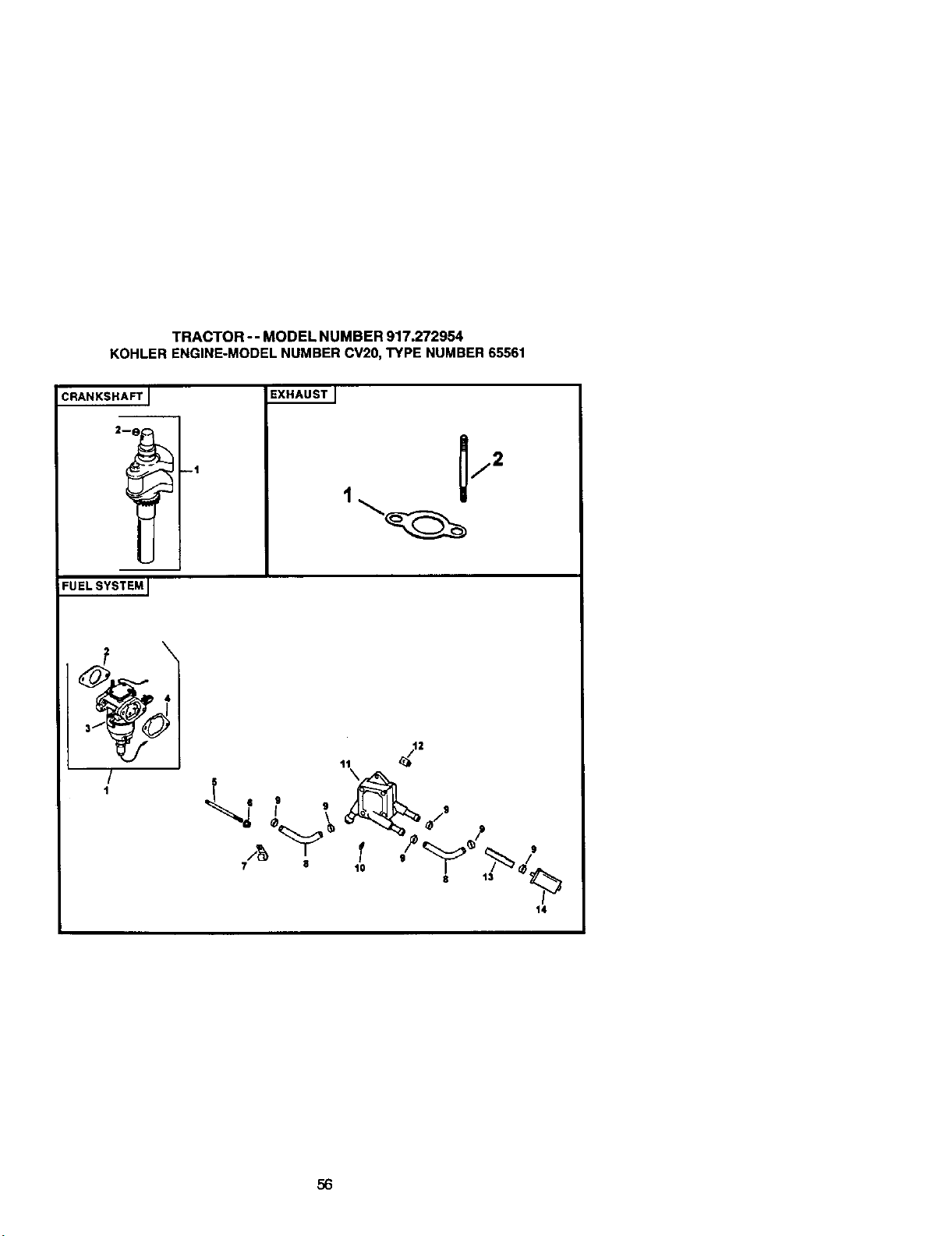
TRACTOR-- MODEL NUMBER 917.272954
KOHLER ENGINE-MODELNUMBERCV20,TYPE NUMBER65561
CRANKSHAFT I
FUEL SYSTEM I
--1
EXHAUST ]
/
I
¼
7 11 10
$
13
9
14
56
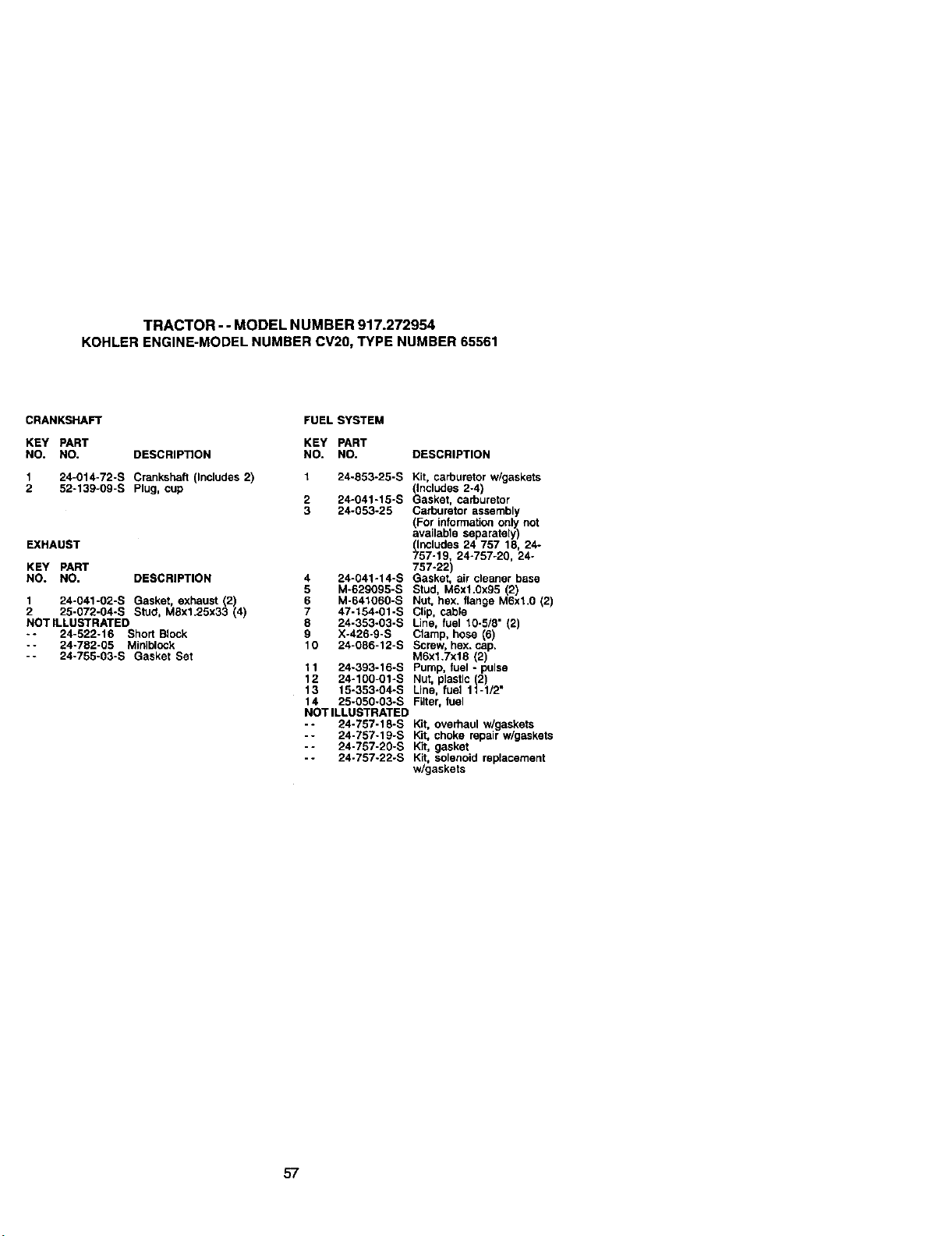
TRACTOR- - MODEL NUMBER 917.272954
KOHLERENGINE-MODELNUMBERCV20,TYPE NUMBER65561
CRANKSHAFT FUEL SYSTEM
KEY PART KEY PART
NO. NO. DESCRIPTION NO. NO.
1 24-014-72-S Crankshaft (Includes 2) 1 24-853-25-S
2 52-139-09-S Plug, cup
2 24-041-15-S
3 24-053-25
EXHAUST
KEY PART
NO. NO. DESCRIPTION 4 24-041-14-S
5 M-629095-S
1 24-041-02-S Gasket, exhaust 2) 6 M-641060-S
2 25-072-04-S Stucl, MSx1.25x33 4 7 47-154-01-S
NOT ILLUSTRATED 8 24-353-03-S
*- 24-522-16 Short Block 9 X-426-9-S
-- 24-782-05 Miniblock 10 24-086-12-S
-- 24-755-03-S Gasket Set
11 24-393-16-S
12 24-100-01-S
13 15-353-04-S
14 25-050-03-S
NOT ILLUSTRATED
-- 24-757-18-S
-- 24-757-19-S
- - 24-757-20-S
- - 24-757-22-S
DESCRIPTION
Kit, carburetor w/gaskets
(includes 2-4)
Gasket, carburetor
Carburetor assembly
(For information only not
availabte separately)
(Includes 24 757 18, 24-
757-19, 24-757-20, 24-
757-22)
Gasket, air cleaner base
Stud, MExl.0x95 (2)
Nut, hax. flange M6xl.0 (2)
Clip, cable
Line, fuel 10-5/8" (2)
Clamp, hose (6)
Screw, hex. cap.
M6xl.7x18 (2)
Pump, fuel - pulse
Nut, plastic (2)
Line, fuel 11-1/2"
Filter, fuel
Kit, overhaul w/gaskets
Kit, choke repair w/gaskets
Kit, gasket
Kit, solenoidreplacement
w/gaskets
57

58

SUGGESTED GUIDE FOR SIGHTING SLOPES FOR SAFE OPERATION
ONLY RIDE UP AND DOWN HILL,
NOT ACROSS HILL
I_ perate your Tractor up and down the face of slopes (not
greater than 15 ) never across the face. Make turns gradu-
ally to prevent tipping or loss of control. Exerc se extreme
caution when changing direction on slopes.

Forrepairofmajorbrandappliancesinyour own home...
nomatterwhomadeit,nomatterwhosold
1-800-4-MY-HOME @ An,pine,dayo_rtgtt
(1-8(X).469-4663) (U,SA andCanada)
WWW.S_61_J.CO_I Wt_PN.,_ieOl'_
Forrepairofcarry-inproductslikevacuums,lawnequipmentand
electronics,callforthenearestSearsPartsand Repair Center.
1-800-488-1222 Any_me,dayorrt_t(U.SAo_y)
wwwm
Forthereplacementparts,accessoriesandowner'smanuals
thatyouneedtodo-it-yourself,callSearsPartsDirecP'!
1-800-366-PART
0_e-36_727B)
6am.-11 p.m,, 7daysaweek
(U.SAo_
To purchaseor inquireabouta SearsSewiceAgreement
or SearsMaintenanceAgreement:
1-800-827-6655 (U.S.A.) 1-800-361-6665 (Canada)
7&m. - 5p,m.,CST. Mort.- Sat 9 am. - 8 p.rn.EST, M- F, 4p.m.Sat,
Parapedrse_ciodemparaci_a AuCanadapoursen,iceenfr'_:
demi_to,yparaom_r'arpiezas: I.SIX).LE..FOYERMC
1"888-SU-HOGARsu (1-800-53_
(1-888784-6427) _Nvw.seers.ca
® Registered Trademark / "n_Trademark I s_ Sewice Mark of Sears, Roebuck and Co.
® Marca Registreda / TM Mama de Fdbdca / _MMama de Servicio de Sears, Roebuck and Co.
MCMarque de commerce / uo Marque d_pos_e de Sears, Roebuck and Co.
179476 05.01.01 RH Printed in U.S.A.


