
Owner's Manual
CRRFTSMRW
42-inch Universal
Tow Behind
POWER MOWER
Model no. 486.243291
CAUTION:
Before using this power mower,
read this manual and follow all
its Safety rules and Operating
instructions.
• Safety Instructior_:_
• Assembly
• Operation
• Maintenance
• Parts
Sears, Roebuck and Co, Hoffman Estates, IL 60179 USA
TABLE OF CONTENTS
_/ARRANTY ................................................................ 2
b_,FET'( RULES ....................................................... 2-4
._ONTENTSOF CARTON ........................................... 5
_SSEMBLY .............................................................. 6-8
_IRING SCHEMATIC ................................................. 9
OPERATION ......................................................... 10-14"
MAINTENANCE .................................................... 15-17
SERVICE AND ADJUSTMENT .............................. 18,19
STORAGE ................................................................. 21
REPAIR PARTS.................................................... 22-33
LIMITED ONE YEAR WARRANTY ON POWER MOWER ATTACHMENT
Forone (1) year from the dateof purchase,Ifth(sPower Moweris maintained, lubricatedand tunedup according
to theinstructionsin the OwneCsManual, Searswil( repairor replace, free ofcharge, anyparts that-,re
defective in materialor workmanship.
ThisWarranty does not cover:
• Expendable itemswhichbecome wornduringnormal use,such as belts or cutting blades.
• Repairsnecessarybecauseofoperatorabuse, negligence,Improper storageor accidentorthe.tailureto maintain
the equipmentaccordingto the instructionscontainedin the Owner'sManual.
• Power MowerAttachmentused for commercialor rental purposes.
WARRANTY SERVICE IS AVAILABLE BY RETURNING THE POWER MOWER TO THE NEAREST SEARS
SERVICE CENTER IN THE UNITED STATES,
ThisWarranty gives you specificlegalrights,andyou may alsohaveotherrightswhichmay varyfrom statetostate.
SEARS, ROEBUCK AND CO., D/817 WA, Hoffman Estates, IL 60179
A
SAFETY RULES
Safe Operation Practices for Tow Behind Mowers
WARNING: This cuttingmachine iscapable ofamputatinghandsand feet and throwingobjects. Failureto
observethe followingsafety instructionscould resultinsedousinjuryor death.
L
GENERAL OPERATION
Read, understand,and fotldwall instructionsin the
manualand on the machinebefore starting.
Read th!soperator'smanual carefully. Become
familiar withthe controls and know howto operate
yourmower properly.
• Only altowresponsibleadults,who are familiar with
the instructions,to operatethe machine.
• Clear the area of objectssuchas rocks,toys,wire,
etc., whichcould be pickedup and thrown bythe
blade,
• Be surethe area isclear of,otherpeople before
mowing. Stop machine if anyoneenters the area.
,, Never carry passengers.
• Do not mow in reverse unlessabsolutely
necessary, Always look downand behindbefore
and while..,acking.
o
41
2
Be aware of the mower dischargedirectionand do
not pointit at anyone. Do notoperatethe mower
withoutthe guard in place.
Slow down before turning.
Never leave a runningmachineunattended.
Alwaysturn offblades, andstop engine.
Turn offbladeswhen not mowing.
Mow onlyin daylightor goodartificiallight.
Do not operatethe machinewhileunderthe
influenceof alcoholor drugs.
Watch for trafficwhen operatingnear or crossing
roadways.
Use extracare when loadingor unloadingthe
machineintoa trailer ortruck.
Do not attempt to operateyourtractoror mower
when notin drivers seat.
Disengagepowerto mowerand stopengine when
transportingor notin use.
• Exercise specialcare when mowing aroundfixed
objectsin orderto preventthe bladesfrom stdking
them. Never deliberately runtractoror mower onto
or over any foreign object.
• Use mower only as the manufacturerintendedand
as describedin this manual.
• Do not operate mower ifit has been dropped or
damaged in any manner. Always have damage
repaired before usingyourmower.
• Alwayswear safety glassesor eye shieldswhen
startingand while usingyour mower.
• Dress properly. Do not.operate mowerwhen
barefoot or wearing opensandals. Wear onlysolid
shoeswith good tractionwhen mowing.
• Always make cuttingheight adjustmentsbefore
starting yourmower. Never attemptto do this while
the engine is running.
• Keep youreyes and mindon your mower and the
area being cut. Do not let otherinterests distract
you.
• Do not put handsor feet near or under rotating
parts. Keep clear ofthe dischargeopeningat all
times.
• Before cleaning, inspecting,or repairing your
mower, stopthe engine and make absolutelysure
the bladeand all movingparts have stopped. Then
disconnectthe spark plugwire and keep itaway
from the spark plugto prevent accidental starting.
• Do notoperate your mower if itvibrates
abnormally. Excessive vibration isan indicationof
damage; stopthe engine,safely checkfor the
cause of vibration and repair as required.
• Never operate yourmowerwithout properguards,
plates, or othersafety devices in place.
I1. SLOPE OPERATION
Slopesare a major factor related to loss-of-controland
Upover accidents, whichcan resultin severe injuryor
death. All slopesrequire extra caution. If you feet
uneasyon it, do not mow it.
DO:
• Mow up and down slopes, not across.
• Remove obstaclessuchas rocks,tree limbs, etc.
• Watch for holes, ruts, or bumps. Uneven terrain
could overturnthe machine. Tall grass can hide
obstacles.
• Use slowspeed. Choose a low gear sothat youwill
nothave to stop or shiftwhile onthe slope.
,P Followthe manufacturer'srecommendationsfor
wheel weights or counterweightsto improve
stability.
• Keep all movement on the slopes slow and gradual.
Do not make sudden changes in speed or direction.
• Avo_ starting or stopping on a stope. If tires Lose
traction, disengage the blades and proceed slowly
straight down the slope.
DO NOT:
• Do not tum on slopes unlessnecessary,and then,
turnslowlyand gradually downhill,if possible.
• DOnot mow near drop-offs,ditohes,or
embankments. The mower could suddenlyturn
over if a wheel isover the edge of a cliff or ditch,or
if an edge caves in.
• Do not mow on wet grass. Reducedtraction cot_ld
cause sliding.
IlL CHILDREN
Tragic accidentscan occurifthe operatoris not alertto
the presenceof children. Childrenare often attracted
to the machineand the mowingactivity. Never assume
that childrenwillremain where youlast sawthem.
• Keep childrenout ofthe mowingarea and under
the watchfulcare of another responsibleadult..
• Be alert endturn machine off ifchildrenenter the
area.
• Before and when backing,look behind and down
for small children.
• Never carry children. They may fail off and be
seriouslyinjuredor interfere withsafe machine
operation.
• Never allowchildrento operatethe machine.
• Use extra care when approachingblindcomers,
shrubs,trees, or other objectsthat may obscure
vision.
IV. SERVICE
• Use extra carein handlinggasolineand otherfuels.
They are flammable and vapors ere explosive.
• Use only an approved container.
,,* Never remove gas cap or add fuel withthe engine
running.
• Allow engine to cool before refueling. Do not
smoke near or while operating mower.
• Never refuel the machine indoors.
• Never storethe machine or fuel container inside a
room where there is an open flame,such as with a
gas water heater.
• Never run a machine inside a c!osed area.
• Keep nuts and bolts, especially blade attachme_
nuts,tight end keep equipment in good conditio;_.
• Never tamper with safety devices. Check their
proper operation regularly.
• Keep maciline free of grass, leaves, or other debris
build-up. Clean oil or fuel spillage. Allow machine
to cool before storing.
• Stop and inspect the equipment if you stdke an
object. Repair, if necessary, before restarting.
• Never make adjustments or repairs with the engine
running.
• Mower bladesare sharpand can cut. Wrap the
blade(s)or wear gloves, and use extra caution
when servicingthem.
• Check brake operationfrequently, Adjustand
service as required.
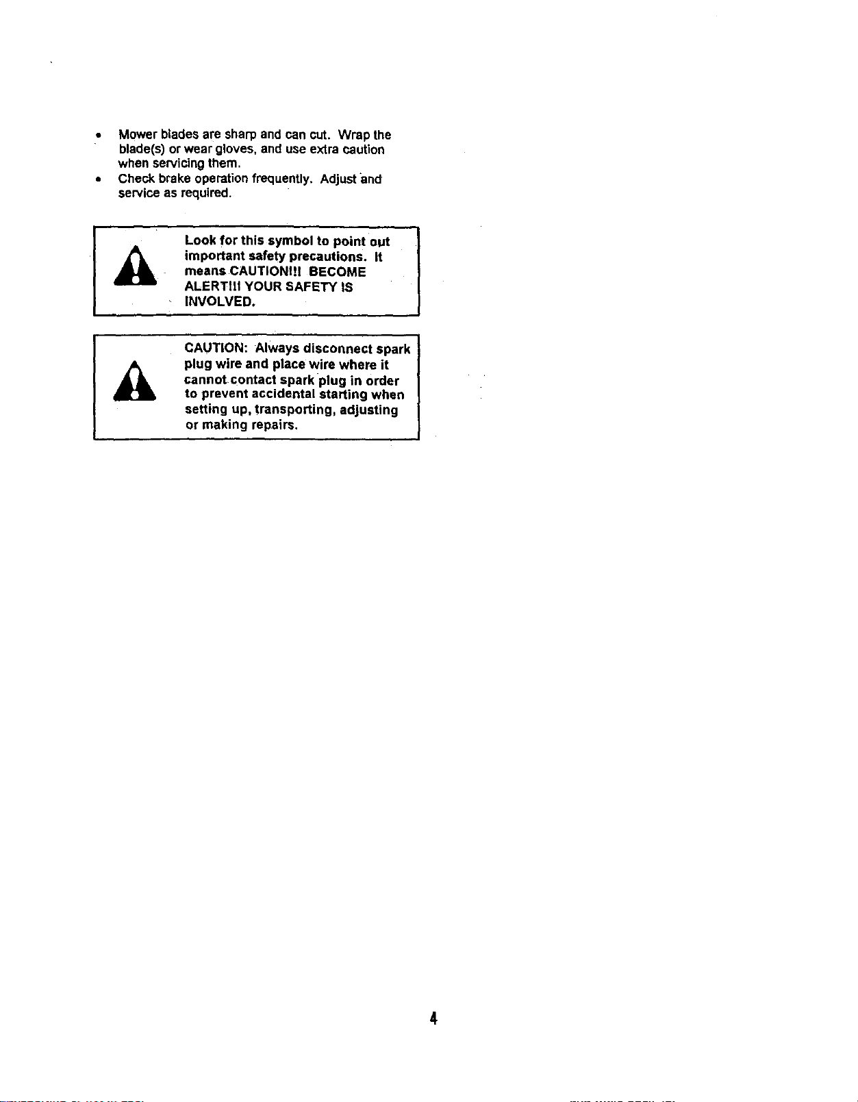
Look for this symbol to point out
important safety precautions. It
means CAUTION!II BECOME
ALERTIII YOUR SAFETY IS
INVOLVED.
CAUTION: Always disconnect spark
plug wire and place wire where it
cannot contact spark plug in order
to prevent accidental starting when
setting up, transporting, adjusting
or making repairs.
4

Please read and keepthis manual. The instructionswill
enable you to assemble and maintain yourPower
Mower property.Always observethe "Safety Rules."
Record serial number and date of purchase in space
provided below.
MODEL
NUMBER: 486.243291
SERIAL
NUMBER:
DATE OF
PURCHASE:
The model and serial numbers willbe found on a
plate attachedto the right side of the Drive Housing.
You should record both serial number and date of
of purchaseand keep in a safeJ_lacefor future
reference.
WARNING: This unit is equipped with an
internal combustion engine and should
not be used on or near any unimproved
forest-covered or grass-covered land
unless the engine's exhaust system is equipped
with a spark arrester meeting applicable local or
state laws (if any). If a spark an'ester is used, it
should be maintained in effective working order by
the operator.
In the state of California the above is required by
;law (Section 4442 of the CaliforniaLPublic Resources
Code). Other states may have similar laws. Federal
laws apply on federal lands. A spark arrester for the
muffler is available through your nearest Sears
IAuthorized Service Center.
PRODUCT SPECIFICATIONS
HORSEPOWER: 8.0
DISPLACEMENT: 19.4 CU. IN.
GASOLINE CAPACITY: 3.QUARTS
GASOLINE TYPE: UNLEADED REGULAR
OIL TYPE (API-SF/SG): SAE 30 (ABOVE 32°F)
SAE 5W-30 (BELOW 32°F)
T I ,,
OIL CAPACITY: 3.0 PINTS
SPARK PLUG: CHAMPION RJ19-LM
(GAP: .030") STD361458
VALVE CLEARANCE: INTAKE: .005 - .007 IN.
EXHAUST: .009 - .011 IN.
BLADE BOLT TORQUE 35-40 FT. LBS.
TIRE PRESSURE 10 PSI
WIDTH OF CUT 42 INCHES
i ii
CONTENTS OF CARTON
PARTS PACKED SEPARATELY IN CRATE
PARTS B_AG
MOWER DECK
HITCH ASSEMBLY _
PARTS BAG CONTENTS
CABLE GUIDE (2)
OPERATOR PRESENCE SEAT
1/2 CABLE CLIP (3)
318 CABLE CLIP (3)
_SCREW (3)
ASSEMBLY
REMOVING UNIT FROM CRATE
• Remove top boards.
• Remove two Boltsfrom frontof cratewhichhold
shippinganchors.
• Remove two Boltsfrom bottom at rear of crate
whichhold shipping anchors.
• Remove HitchAssembly and Parts Bagfrom crate.
• Remove frontof crate.
• Roll Mower ronsardout ofcrate.
• Remove RollerBoltfrom Front Roller, remove
shippinganchorsand reinstallRollerBolt.
• Remove Nuts from HeightAdjustmentStropsand .
remove shippinganchorsfrom eachside ofinower.
ReinstallNutsto HeightAdjustmentStraps,then
loosen1/4 tum to allowstrapsto pivotfrae!y.
• Check all lOOsepartsand bag contentsagainst
Crate Contentsand Bag Contentsillustrationon
page 4. If any partis missingordamaged contact
the store where you pumhasedthe unit.
t
CAUTION [
Before starting to assemble mower,
remove spark plug wire from plug of
mower engine.
OPERATOR ORIENTATION
When dghtand leftare mentionedinthis manual, it
meansyourrightand your leftwhen you are seated
behindthewheel in the operatingposition.
ENGINE OIL
VERY IMPORTANT:
Engine mustbe filledwith oil beforeoperation. See OIL
& FUEL RECOMMENDATIONS in engine Owner's
Manual for correctfillinginstructionsand oilfill capacity.
INSTALL TOWBAR TUBE TO REAR
QUADRANT
Cut and remove the PlasticTie whichholdsthe
Wire Harnessand the Clutch Cable to the Rear
Quadrant (See Fig. 1)
Remove two3/8 Bolts,two 3/8 LockNuts and one
3/8 Flat Washer from the rear of theTowbar Tube.
Place tube intoRear Quadrant, align holes, insert
3/8-16 x =.1/2 Hex Boltthroughrear holeof tube.
Secure tightlywith 3/8-16 Lock Nut then loosenNut
1/4 turnto allow tube to pivot freely InsideRear
Quadrant.
• Assemblea 3/8 Flat Washer ontoa 3/8-16 x 2-1/2
Hex Bolt.
• InsertBoltand Wisher throughslotof Rear
Quadrant and holein Towbar Tube.
• Secure tightlywith 3/8-16 LockNut then loosenNut
114turnto allowtube to pivotfreely insideRear
Quadrant.
NOTE: Tow'oarTube must pivotfreely insideRear
Quadrantwhen latch ispulledfrom notch_
INSTALL CLUTCH CABLE AND WIRE
HARNESS TO TOWBAR TUBE.
• Unwrapthe Wire Harnessand the ClutchCable
from AroundThe Engiee.
• Laythe Clutch Cable alongthe leftside ofthe
Towbar Tube and the Wire Harnessalongthe right
side ofthe Towbar Tube.
• Installthree 3/8" Cable Clips onthe ClutchCable
andthree 1/2" Cable Clipsontothe Wire Harness.
• Align all six Cable Clipswiththe holesin the Towbar
Tube and secure them withthree #10 Self-Tapping
Screws.
INSTALL CLUTCH CABLE TO THE HITCH
ASSEMBLY
• Remove one 1/4 inchNut and Boltfrom the eyelet
ofthe Clutch Cable. (See Fig. 1)
• Remove one of the 5/16 inchNutsfrom the
threaded end ofthe ClutchCable Housingandturn
the second Nut all the way ontothe threads.
Insertthe ClutchCable andthe loose5/16 inchNut
throughthe slottedholein the Cable Guide ofthe
HitchAssembly.
NOTE: The loose5/16 Nut mustbe cockedsideways
slightlyto get it throughthe Slot.
• Reinstallthe loose 5116inch Nut ontothe Clutch
Cable Housingto secure Cable'Housing.
• Alignthe eyelet of the C_utchCable withthe hole in
the Mower Blade Clutch Lever and securewith one
1/4 inchBoltand one 114inchNut.
See DRIVE TENSION in the SERVICE AND
ADJUSTMENTS Sectionof this manualfor proper
ClutchCable adjustment.
R
BOLT3/8 X 2-t/2
"1
REAR Q UADFL_NT #
3/8 LOCK NUT
\
#10 SELF
TAPPING
SCREW_. " SWITCH
T WASHER _ MOUNTING
I ERACKET
3/8 CABLE CLIP (3)_i _
, CLUTCH CABLE
1/2 CABLE CUP
ANCHOR
TOW BAR TUBE
WIRE HARNESS.
HITCH ASSEMBL
ONIOFF
SWITCH
HG NUT
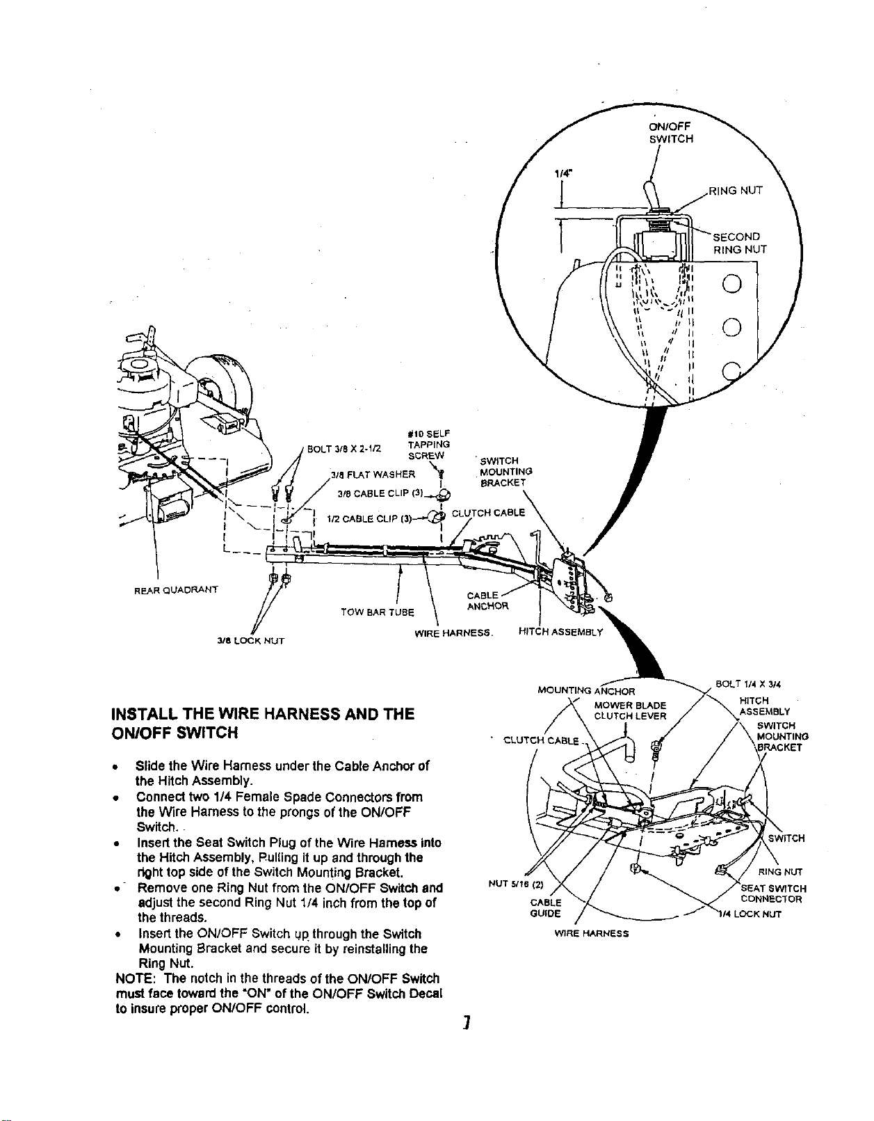
INSTALL THE WIRE HARNESS AND THE
ONIOFF SWITCH
• Slide the Wire Hamess underthe Cable Anchorof
the Hitch Assembly.
• Connect two 114Female Spade Connectorsfrom
the Wire Harnessto the prongsof the ON/OFF
Switch.
• Insertthe Seat Switch Plugof the Wire Harnessinto
the HitchAssembly, Rulnng it up and throughthe
righttop side ofthe Switch MountingBracket.
• Remove one Ring Nut from the ON/OFF Switchand
adjustthe second Ring Nut 1/4 inchfromthe top of
thethreads.
• Insertthe ON/OFF Switch up.through the Switch
MountingBracket and secure it byreinstalling the
Ring Nut.
NOTE: The notchinthe threadsof the ON/OFF Switch
must face toward the "ON"of the ON/OFF Switch Decal
to insureproperON/OFF control.
MOUNTING ANCHOR
MOWER BLADE
CLUTCH LEVER
NUT 5116(2)
CABLE
GUIDE
WIRE HARNESB
7
BOLT 114X 3/4
HITCH
ASSEMBLY
SWITCH
MOUNTING
RING NUT
SEAT 8WrTCH
CONNECTOR
LOCK NUT
CABLE GUIDE
\
OPERATOR PRESENCE SEAT
CONNECTOR
SEAT STRAPS
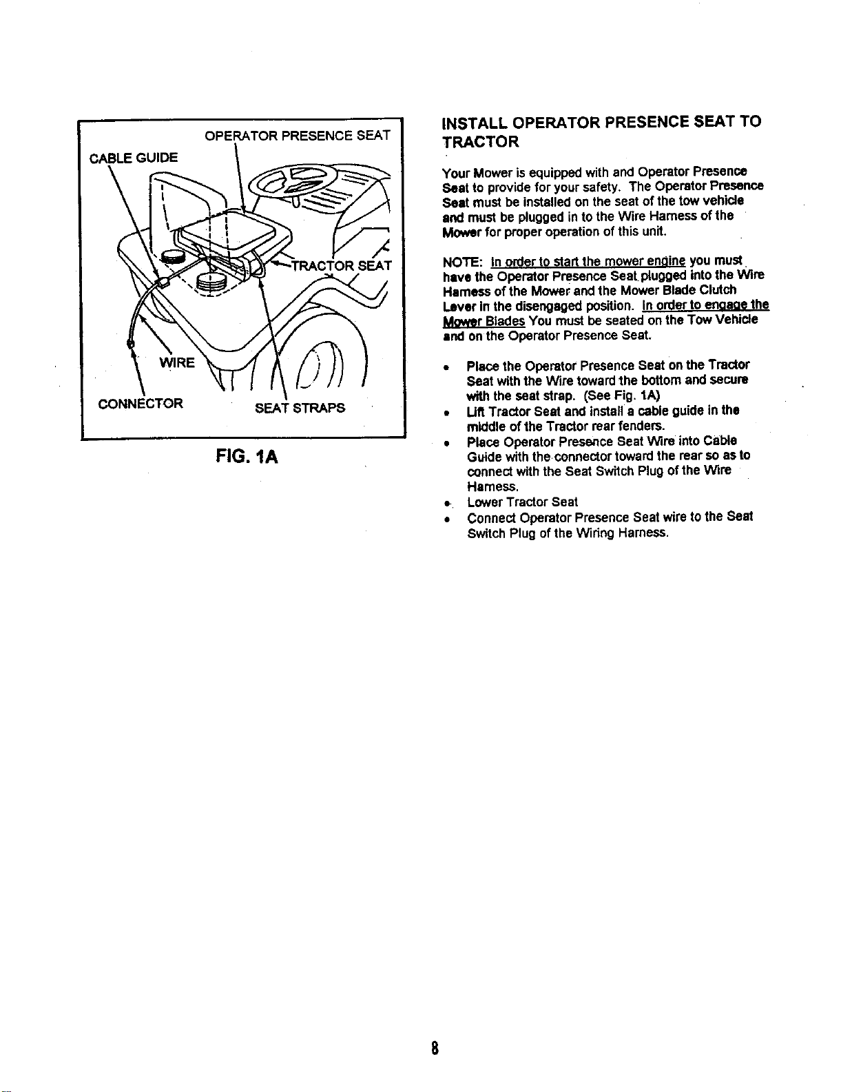
FIG. IA
INSTALL OPERATOR PRESENCE SEAT TO
TRACTOR
Your Mower is equippedwithand Operator Presence
Seat to providefor yoursafety. The Operator Presence
Seat mustbe installedon the seat of thetow vehicle
and must be pluggedinto the Wire Harnessof the
Mower for properoperationofthis unit.
NOTE: In order to start the mowerenoine you must
have the Operator Presence Seat.pluggedintotheWire
Harnessof the Mower and the Mower BladeClutch
Lever in the disengagedposition. LD_L_JPJ_II_J_t
Mower BladesYou must be seated on theTow Veblcle
and onthe Operator Presence Seat,
• Placethe Operator Presence Seat onthe Tractor
Seat with the Wire towardthe bottomand secure
with the seat strap. (See Fig. 1A)
• LiftTractor Seat and installa cable guide inthe
middle ofthe Tractor rear fendera.
• Place Operator Presence Seat Wira intoCable
Guidewith the connectortowardthe rear soas to
connectwith the Seat Switch Plugof theWire
Hamess.
LowerTractor Seat
• Connect Operator Presence Seat wire tothe Seat
Switch Plug ofthe Wiring Harness.
8
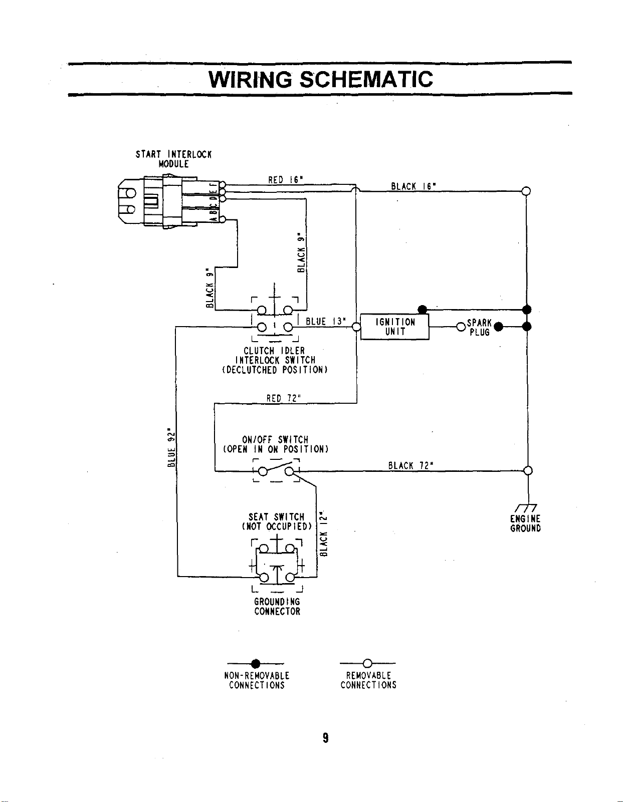
WIRING SCHEMATIC
iiii
START INTERLOCK
MODULE
I.L
RED 16"
P_BLUE 13".
CLUTCH IDLER
INTERLOCKSWITCH
(DECLUTCHEDPOSITION)
RED 72"
BLACK 16"
IGNITION
UNIT
ONIOPF SWITCH
(OPEN IN ON POSITION)
BLACK 72"
SEAT SWITCH _,
(NOT OCCUPIED) -
L __ _.I
GROUNDING
CONNECTOR
ENGINE
GROUND
A
v
NON-REMOVABLE
CONNECTIONS
C)
REMOVABLE
CONNECTIONS
9
I •
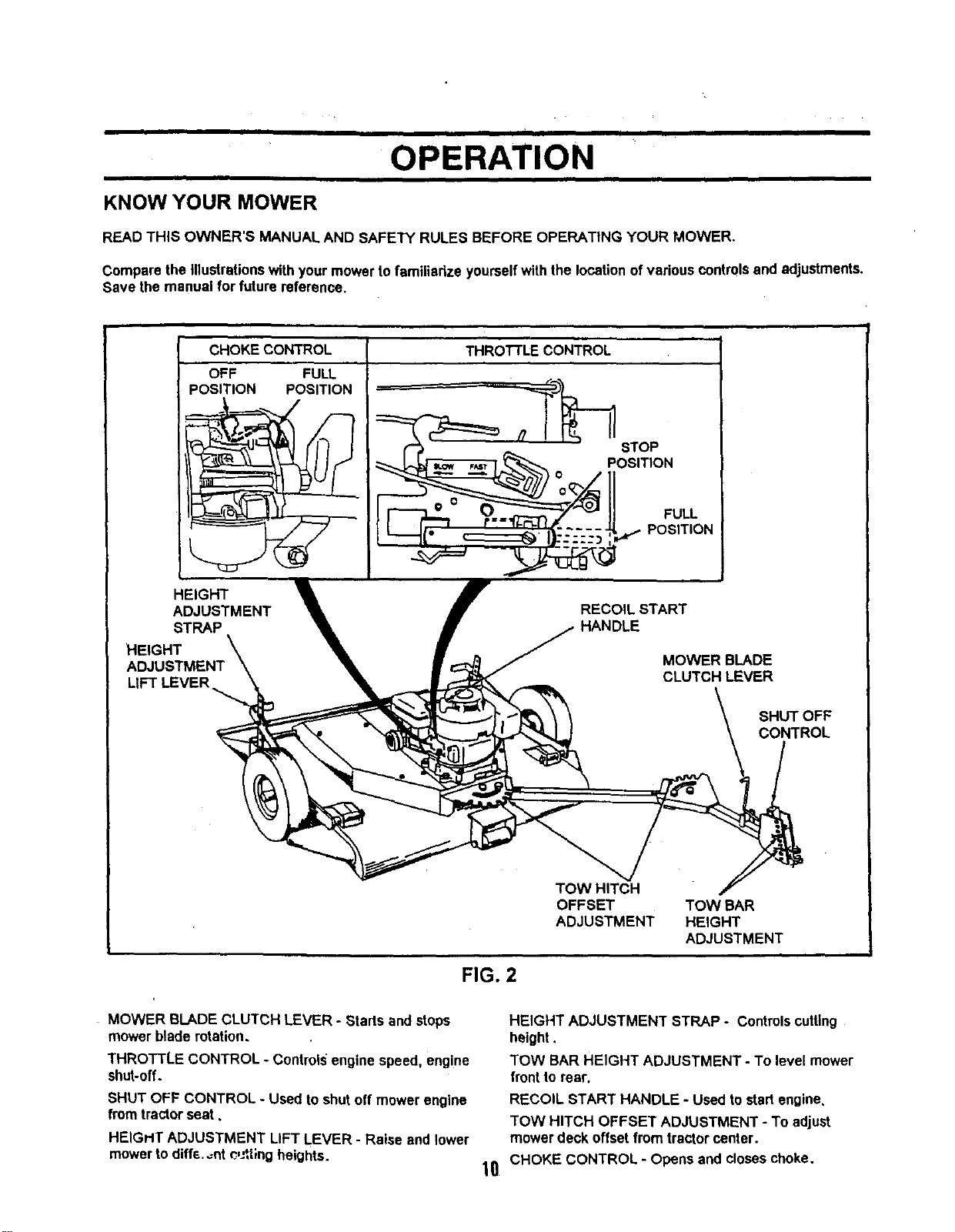
OPERATION
KNOW YOUR MOWER
READ THIS OWNER'S MANUAL AND SAFETY RULES BEFORE OPERATING YOUR MOWER.
Compare the illustrationswith yourmowerto familiadze yourselfwith the locationof variouscontrolsand adjustments.
Save the manual for future reference.
CHOKE CONTROL
OFF FULL
POSITION POSITION
THROTTLE CONTROL
HEIGHT
ADJUSTMENT
STRAP
RECOIL START
HANDLE
MOWER BLADE
CLUTCH LEVER
TOW HIT_ R
OFFSET TOW BAR
ADJUSTMENT HEIGHT
ADJUSTMENT
FIG. 2
MOWER BLADE CLUTCH LEVER - Starts and stops
mower bladerotation.
THROTTLE CONTROL - Controlsengine speed, engine
shut-off.
SHUT OFF CONTROL - Used toshut off mower engine
from tractorseat.
HEIGHT ADJUSTMENT LIFT LEVER - Raise and lower
mowertodiffe.._nt_,J*,tlngheights.
HEIGHT ADJUSTMENT STRAP - Controlscutting
height.
TOW BAR HEIGHT ADJUSTMENT - To level mower
frontto rear.
RECOIL START HANDLE - Used tostartengine.
TOW HITCH OFFSET ADJUSTMENT - To adjust
mower deck offsetfrom tractorcenter.
10 CHOKE CONTROL - Opens and closeschoke.
The operation of any mower can result in foreign objects being thrown into the ayes,
which can result In severe eye damagel Always wear safety glasses or eye shields
before starting your mower and while mowing. We recommend wide vision safety mask
for over the spectacles or standard safety glasses,
CHILDREN
Tragic accidents can Occur if the operator is not alert to the presence of children.
Children are often attracted to the machine and the mowing activity. Never
assume that children will remain where you last saw them.
HOW ToUSE YOUR MOWER
STOPPING
• Move blade clutch lever to Off position.
• Move engine shut off switch to Off position.
• Move engine throttle to Stop position.
STARTING
• Move engine shut off switch to On position.
• Move engine throttleto Ful!position.
• Move choke to full
• Move blade clutchlever to Off position.
• Pull startrope.
• Move engine choke to Off positionafterengine
starts.
USING
• Sit on tractorseat.
• Raise blade clutchlever to Engage position.
• Operate tractorat mediumgroundspeed, 3-4 MPH.
• Refer to Safety Rules on page 3 regardingoperation
of mower onslopes.
TRANSPORTING
• Shut off engine.
• Place mowerdeck in the highest positiondirectly
behindtractor.
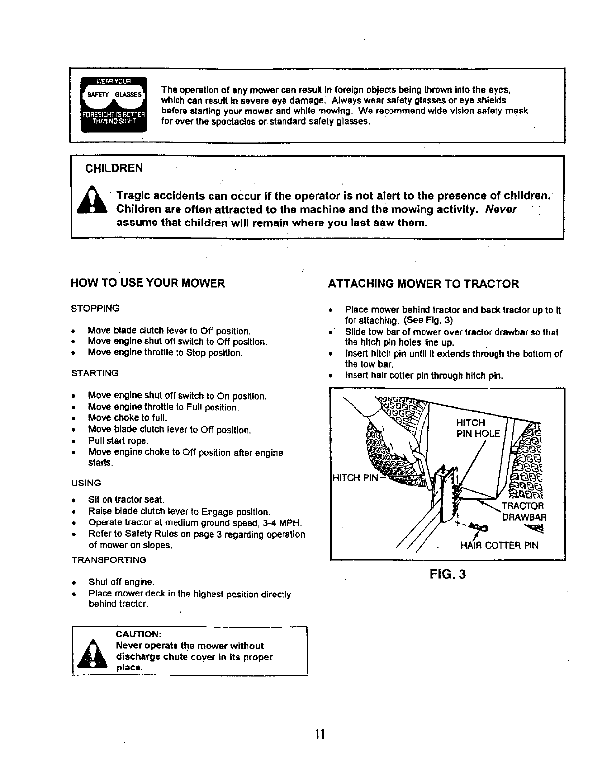
ATTACHING MOWER TO TRACTOR
• Place mower behindtractor and back tractorupto it
for attaching. (See Fig. 3)
• Slide tow bar of mower over tractordrawbar sothat
the hitchpinholes lineup.
• Inserthitchpin untilit extends throughthe bottomof
the tow bar.
• Inserthair cofter pinthroughhitchpin.
HITCH PIN"
TRACTOR
DRAWBA.R
FIG. 3
CAUTION:
Never operate the mower without
discharge chute coyer in its proper
place.
I
11
CUTTING HEIGHT INFORMATION
CAUTION: 1
Shut off mower engine and remove spark|i
plug wire from spark plug before making 1
any adjustments to mower. J
The cuttingheight ra_e isapproximately 1-1/2 to 4-1/2
inches. The_heightsare measuredfrom thegroundto
the bladetip withtheengine notrunning. These heights
are approximateand may vary dependinguponsoil
conditions,heightof grassand types ofgrass being
mowed.
The average lawn shouldbe cutto approximately2-1/2
inchesdudngthe cool seasonandto over3 inches
duringhot months. For healthierand better looking
lawns,mow often andafter moderate growth.
For bestcuttingperformance,grass over6 inchesin
heightshouldbe mowedtwice. Make the firstcut
relatively high,the secondto desired height.
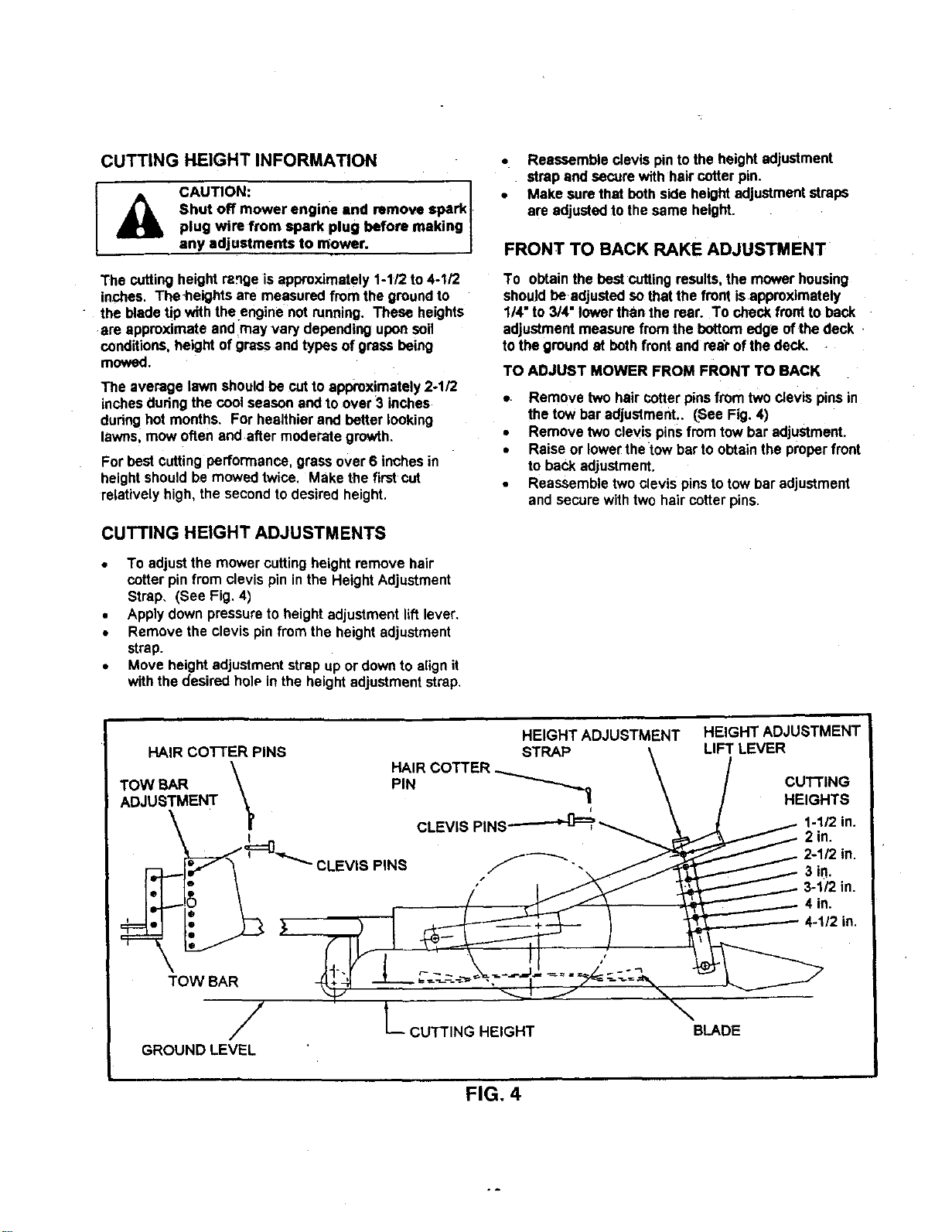
CUTTING HEIGHT ADJUSTMENTS
• To adjustthe mowercuttingheight remove hair
cotter pinfrom clevis pin inthe Height Adjustment
Strap. (See Fig. 4)
• Applydown pressureto height adjustmentliftlever.
• Remove the clevis pinfromthe heightadjustment
strap.
• Move heightadjustmentstrap up or downto alignit
withthe desired holPinthe heightadjustmentstrap.
• Reassemble clevis pintothe height adjustment
strap and secure with haircotterpin.
• Make sure that bothside heightadjustmentstraps
are adjustedto thesame height.
FRONT TO BACK RAKE ADJUSTMENT
To obtainthe best cutting results,the mowerhousing
shouldbe adjustedso thatthe frontisapproximately
1/4"to 3/4" lowerthan the rear. To checkfronttoback
adjustmentmeasure fromthe bottomedge ofthe deck
tothe groundat both front and rear ofthe deck.
TO ADJUST MOWER FROM FRONT TO BACK
• Remove two haircotterpinsfrom twoclevis pinsin
the tow bar adjustment.. (See Fig. 4)
• Remove two clevis pinsfromtow bar adjustment.
• Raise or lowerthe'tow bar to obtainthe properfront
to back adjustment.
• Reassembletwoclevis pinstotow bar adjustment
and securewithtwo haircotter pins.
/
GROUND LEVEL
L CUTTING HEIGHT
HEIGHT ADJUSTMENT
LIFT LEVER
CUTTING
HEIGHTS
1-1/2 in.
2 in.
in.
in.
BLADE
FIG. 4
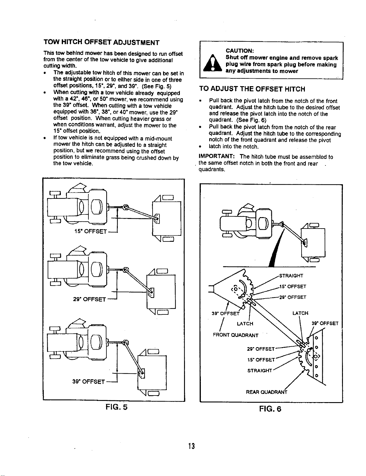
TOW HITCH OFFSET ADJUSTMENT
Thistow behind mower hasbeen designedto runoffset
from the center ofthe tow vehicleto give additional
cuttingwidth.
• The adjustabletow hitchofthis mower can beset in
the straight positionor to eitherside in one of three
offsetpositions, 15", 29", and 39". (See Fig. 5)
• When cuttingwith a towvehicle already equipped
witha 42", 46", or 50" mower,we recommend using
the 3g"offset, When cuttingwith a towvehicle
equippedwith 36", 38", or 40"mower, usethe 29"
offset position. When cuttingheavier grassor
when conditionswarrant, adjustthe mower tothe
15"offsetposition.
• If towvehicle isnot equippedwitha mid-mount
mower the hitchcan be adjustedto a straight
position, but we recommend usingthe offset
positionto eliminate grass being crusheddownby
thetow vehicle.
CAUTION:
Shut off mower engine and remove spark
plug wire from spark plug before making
any adjustments to mower
TO ADJUST THE OFFSET HITCH
• Pull backthe pivot latch from the notchofthe front
quadrant. Adjustthe hitchtube to the desired offset
and release the pivot latch into the notchof the
quadrant. (See Fig. 6)
• Pull backthe pivotlatch from the notchofthe rear
quadrant. Adjustthe hitchtube to the corresponding
notchof the frontquadrantand releasethe pivot
• latch intothe notch.
IMPORTANT: The hitchtube must be assembledto
• the same offset notchin boththe frontand rear
quadrants.
15"OFFSET
FIG: 5
39" OFFSET
LATCH
FRONT QUADRANT
;"OFFSET
LATCH
39" OFFSET
29"OFFSET
'i
L
REARQUADRANT
FIG. 6
13
BEFORE STARTING ENGINE
MOWING PROCEDURES
• Fill engine with oil (See MaintenanceSection of
this manual for properprocedureand requirements)
• Add Gasoline, Fill Fueltank usingfresh clean
unleadedgasoline.
I cAuT'°N;II,
Fill to bottom of fuel tank filler neck. Do
not overfill. Wipe off any spilled oil or
fuel. Do not store, spill or use gasoline
near open flame.
CAUTION:
Tragic accidents can occur if the
operator is not alert to the presence of
children. Children are often attracted to
the machine and the mowing activity.
NEVER assume that children will remain
where you last saw them.
CAUTION:
Never carry children. They may fall off
and be seriously injured or interfere with
safe operation,
TO START ENGINE
L
CAUTION:
Keep the blade clutch lever in
"Disengaged" position when starting
engine.
• Make sure spark plugwire is properlyconnected.
• Place choke controiin "CHOKE=positionifthe
engine iscold. A warm engine may not require
chokingto start.
• Move engine throttleto full position.
• Grasp starter handle with one hand. Pull ropeout
.slowlyuntilengine reaches startof compression
cycle(ropewill pullslightlyharderat this point).
• Pull ropewith a rapia, continuous,full arm stroke.
• Keep a firm gripon starter handle and let rope
rewindslowly. Do notlet starter handlesnap back
againststarter.
• When engine starts move choketo openposition.
• Allow engineto warm up for a few minutesbefore
engagingblades.
NOTE: If at a high altitude (above 3000 feet) or in cold
temperatures (below 32°F), the carburetorfuel mixture
may need to be adjustedfor bestperformance. See
Service and Adjustmentssectionofthe engine manual.
BREAKING IN YOUR MOWER
Break in yourbelts, pulleys and engine before you
actuallybegin mowing.
• Start engine, engage blade control to start blades
rotating and allow blades to rotate approximately
five minutes to break in mower and engine.
CAUTION:
Check area under and around mower for
ary objects that could be thrown from
under mower. Make sure'that mower
discharge area is clear.
• Mowingshouldbe started withtractorin low gear
I and speed increasedonlyas mowing conditionswill
safely permit.
• Mowerwill performat itsbestwhen enginethrottleis
set for full throttle.
You will obtainbetter mowingresults ingrassy areas
if they are mowed when the grass isapproximately
4" to 5" maximum height. While your mower will cut
grass taller than 5", you will notice e substantial
increase in engine power required and some change
in the finished appearance of the area mowed.
Mowing conditions will vary from place to place,
including the types of grass which are being mowed,
such as fine stalk, coarse stalk, dense or sparse
grasses. When mowing tall grassyou may find that
the pressure of wheel tracks may cause certain
grasses to be pushed downward so they will not be
mowed properly. If this condition exists you may
have to mow the area twice, the first mowing with
the mower raised and the second mowing at the
desired height that you have chosen. If it is
practical, you will achieve better results if the
second mowing is a right angle in travel to the
previous mowing.
Do not mow grasswhen it is wet. Wet grass will
plug mower and leave undesirable clumps. Allow
grass to dry before mowing.
Always operate mower engine at full throttle when
mowing to assure better mowing performance and
proper discharge of material. Regulate ground
speed by selecting a gear low enough to give the
best cutting performance and quality of cut.
When operating any attachmentselect a ground
speed that willsuit the terrain and give the best
performance for the attachment bein_q_us_ed:_
When mowing slopes, always mow them up and
down at slow speed. Never mow across slopes.
See Slope Operation section of Safety Rulesfor
further instruction on slope mowing.
1A
MAINTENANCE
GENERAL RECOMMENDATIONS
The warrantyon this attachment does notcover items
that have been subjectedto operatorabuse or
negligence. To receive full value from the warranty,
operatormustmaintain unitas instructedin this manual.
Some adjustmentswill needto be made periodicallyto
properlymaintain yourunit. All adjustmentsin the
Service and Adjustmentssectionofthis manual should
be checked at leastonce each season.
Once a year you shouldreplacethe spark plug, clean or
replace air filter, and checkbladesand belts for wear. A
new spark plug and clean air filter assure properair*fuel
mixture and help yourengine run better and last longer.
BEFORE EACH USE
• Check engine oillevel.
• Check forloose fasteners
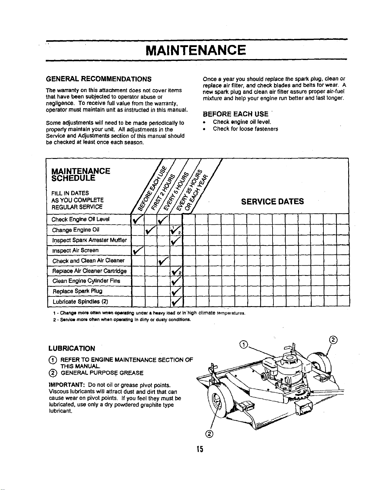
MAINTENANCE
SCHEDULE
FILL IN DATES
ASYOU COMPLETE
REGULARSERVICE
Check EngineOil Level _
Change EngineOil _
irlsPect SparkArresterMuffler
,/
Inspect Air Screen Vf
Check and CleanAirCleaner
ReplaceAirCleaner Cartridge El
CleanEngine CylinderFins t#/"
v"
Replace Spark Plug
LubricateSpindles(2)
1 - Change more often when operiting unaer • heavy load or in'high climate temperatures,
2 - Service more often when operating In dirty or dusty conditions.
SERVICE DATES
LUBRICATION
(_ REFER TO ENGINE MAINTENANCE SECTION OF
THIS MANUAL.
(_ GENERAL PURPOSE GREASE
IMPORTANT: Do not oilor grease pivotpoints.
Viscouslubricantswill attractdust and dirtthat can
causewear on pivotpoints. If youfeel they must be
lubricated, useonlya dry powderedgraphitetype
lubricant.
®
®
15
Disconnect spark plug wire before performing any maintenance (except carburetor adJuatmen'
to prevent accidental starting of engine.
Prevent f resv Keep the engine free of grass leaves sped oil or rue Remove fuel from tank
• _ w
before tipping unit for maintenance Clean muffler area of all grass, dirt and debr e.
Do not touch hot muffler or cylinder fins as contacl may cause burns.
ENGINE
LUBRICATION
Change the oilafter the firsttwo hoursof operationand
every 25 hoursthere after or at least oncoa year if the
mowerIs not used for 25 hoursin one year.
Change and add oilaccordingto chart below. Do not
overfill. Use a high qualitydetergent oilclassified"For
Service AF, SG, SH," such as Briggs& Stretton
'warranty certified" SAE 30 oil, PartNo. 100005. Use
no specialadditives with recommended oils. Do not mix
oilwith gasoline.
Grades
°F _{) 0 2_ 32 40 SO 100
I_C ,3O _0--OC,3O -2O .10 0 10 2O 3_ ao
* Air cooledengines runhotterthan automotive
engines. The useof mL ii-viscosityoil(such as 10W-
30, Etc.) in ambient temperatures above"40"F (4° C)
willresultin higherthan normaloilconsumption. If
multi-viscosity bit isused, checkthe oillevel more
frequentlyto prevent anypossibleenginedamage due
to lack oflubncetion.
"_ Use of SAE 30 oil below 40" (4° C) will result in herd
starting and possibly engine damage due tO inadequate
lubdcetion.
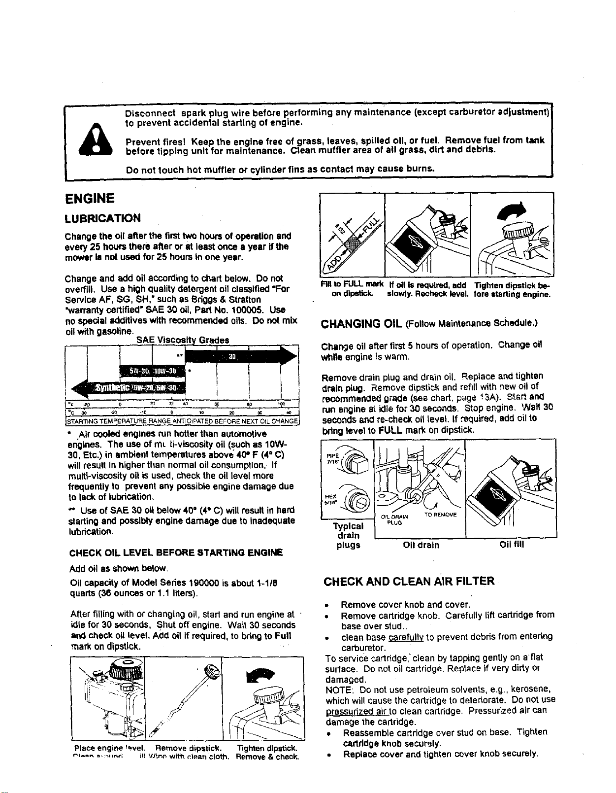
CHECK OIL LEVEL BEFORE STARTING ENGINE
Add oil as shown below.
Oil capacity of Model Series 190000 is about1-1/8
quarts(36 ouncesor 1.1 liters).
After filing withor changingoil, start and runengineat
idlefor 30 seconds, Shut off engine. Wait 30 seconds
and checkoillevel. Add oil if required,to bfiug to Full
mark on dipstick.
Fill to FULL mark If oil is required, add Tighten dipstick be-
on dipstick, slowly. Recheck level, fore starting engine.
CHANGING OIL (FollowMaintenanceSchedule.)
Charv'jeoilafter first5 hoursof operation. Change oil
while engine iswarm.
Remove drain plugand drain oil. Replaceand tighten
drain plug. Remove dipstick and refill with newoil of
recommended grade (see chart, page _.3A). Startar_l
runengine at idle for 30 seconds. Stop engine. Walt 30
seconds and re-check bit level. If ,'_luired, add oil to
bringlevel to FULL mark on dipstick.
7/1
Typical
drain
plugs
OIL t3P,AIN TO RE_4OVE
PLUG
Oil drain Oil fill
CHECK AND CLEAN AIR FILTER
• Remove cover knob and cover.
• Remove cartridgeknob. Carefully lift cartridgefrom
baseover stud..
• clean base _ to preventdebrisfrom entering
carburetor.
To service cartridge, clean by tapping gently on aflat
surface. Do not oil cartridge. Replace if verydirty or
damaged.
NOTE: Do not use petroleum solvents, e.g., kerosene,
which will cause the cartridge to deteriorate. Do not use
pressudzed air.to clean cartridge. Pressurized air can
damage the cartridge.
• Reassemble cartridgeover studon base. Tighten
certddge knobsecurely.
• Replace cover and tightencover knobsecurely.
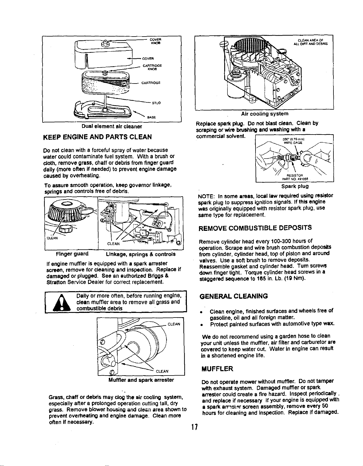
CARTRIDGE
BkSE
Dual element sir cleaner
KEEP ENGINE AND PARTS CLEAN
Do not cleanwith a forcefulspray ofwater because
water could contaminatefuel system. With a brushor
cloth, remove grass, chaff ordebris from finger guard
daily (more often if needed)to prevent enginedamage
caused by overheating.
To assure smoothoperation,keep governorlinkage,
.springsand controlsfree of debris.
Finger guard Linkage, springs & controls
If engine muffler isequippedwith a spark an'ester
screen, remove for cleaningand inapactJon.Replace if
damaged or plugged. See an suthodzed Bdggs &
Stratton Service Deater for correctreplacement.
I' _lk Daily °r m°re °fte'n' bef°re runningengine' I
clean muffler area to remove all grass and
combustibledebris
CLEAN
Muffler and spark attester
Grass, chaff ordebris may clogthe air cooling system,
especiallyafter a prolongedoperationcutting tal!, dry
grass. Remove blower housingand cle_n area shownto
preventoverheating and enginedamage. Clean more
often if necessary.
CLEAN AREA OF
ALL DIRT ANO DEBRtS
Air cooJJng'system
Replace spark plug. Do not blast clean. Clean by
scrapingorwire brushingand washingwith a
commercial solvent.
030" (076 turn)
PART NO 491055
Spark plug
NOTE: In some areas, local law requiredusing resistor
spark plugto suppressignitionsignals.If this engine
was originallyequippedwith resistorspark plug, use
same type for replacement.
REMOVE COMBUSTIBLE DEPOSITS
Remove cylinderhead every 100-300 hoursof
operation.Scrape and wire brushcombustion deposits
from cylinder, cylinderhead, top of pistonand around
valves. Use a soft brushto remove depOsits.
Reassemble gasket and cylinderhead• Turn screws
downfinger tight. Torque cylinder head screwsin a
staggered sequenceto 165 in. Lb. (t9 Nm).
GENERAL CLEANING
• Clean engine, finishedsurfacesand wheels free of
gasoline, oiland all foreignmatter.
• Protect paintedsurfaces withautomotive typewax.
We do not recommend usinga garden hoseto clean
your unitunlessthe muffler, airfilter and carburetor are
covered to keep water out. Water in engine can result
in a shortenedengine life.
MUFFLER
Do not operate mower withoutmuffler. Do not tamper
with exhaust system. Damaged muffleror spark
an'ester could create a fire hazard, Inspectperiodically.
and replace ifnecessary If yourengine is equippedwith
a sparkan_s_r screen assembly,remove every 50
hoursfor cleaning and inspection. Replace if damaged.
17

I
SERVICE AND ADJUSTMENTS
I
BLADE CARE
• For bestresultsmower blades mustbe keptsharp.
the bladescan be sharpenedwith a few strokesofa
file or on a grindingwheel. Do not attemptto
sharpenwhile blades are on mower.
• To remove blade for sharpening,usewooden block
to hold blade whileremovingthe blade mounting
nut. The nuts have right handthreads. (See Fig. 7)
CAUTION: I
Do not handle mower blades with bare
hands, Careless or improper handling
may result in serious injury,
WOOD BLOCK NUT---..-_
BLADE
FIG. 7
• When grinding,take care to maintain blade balance.
Check blade for properbalance before reinstalling
to mower.
• To check and balanceblade use a balancing
machine orfixture as shownin figure 8. File
material oft heavier end of blade until itis balanced.
,_,ON NAIL. DO NOT LET BLADE TOUCH___ -_"
-BENCH. A BALANCED BLADE WILL _._
_REMA[N LEVEL. I
_ '\ NAiL LUBRICATED
WORKBENCH ,WITH DROP OF OIL
FIG. 8
To a sa[isfacto_¥ _=ration,we recommend that
you (_ ,_dold ...ad .s _, d _eplacethem with new ones
before the start of each mowing season.
NOTE: Check nuts and bladesoccasionallyto make
surenuts are tight.
I 4_11 CAUTION: I
Shut off mower engine and remove spark I
plug wire from spark plug before making I
any adjustments or repairs to mower. I
CARBURETOR ADJUSTMENTS
The manufacturer of the equipmenton
which this engine isinstalledspecifiestop
speed at whichthe enginewillbe operated.
DO NOT EXCEED thisspeed.
Differencesin fuel, temperature, altitude or loadmay
requireminor carburetor adjustment. Air Cleaner and
air cleaner cover mustbe assembledto carburetor
before starting engine.
The carburetor on thisengine is low emission, it is
equipped with and idle mixture valve with a limiter (see
inset), which allows some adjustment, and an idle speed
edjustment screw.
ADJUSTMENTS
Start engine and warm up approximately5 minutes
before adjusting. With engine running,placethrottle
controlin SLOW position. Rotate carburetor throttle
lever againstthe idle speedscrewand holdit. Turn idle
speedscrewto obtain 1750 rpm.
Rotate idle mixture valve fulltravel clockwiseandthen
counter clockwise. Finally, positionidle mixture valve in
middle of travel. Check idlespeed and re-adjustto
1750 rpm, if necessary.
Move throttle controlto FAST position, Engine should
accelerate smoothly. If itdoes not, adjustIdle mixture
valve countemlockwise1/8 turn.
CARBUR_OR
THF_O_LE
LEVER
_DLE SPEEO
SCREW
IDLE MLXTURE
VALVE
WITH LiMITER
Carburetor adjustments
18
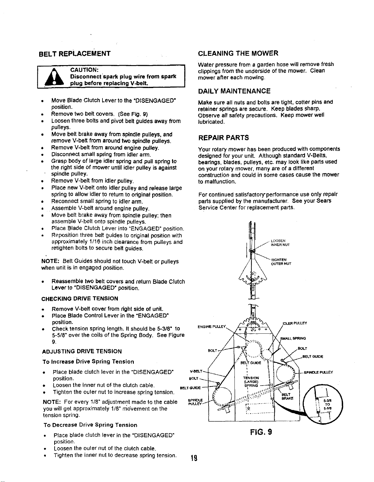
BELT REPLACEMENT
_lk CAUTION:
Disconnect'spark plug wire from spark
plug before replacing V-belt.
• Move Blade Clutch Lever to the "DISENGAGED"
position.
• Removetwo belt covers. (See Fig. 9)
• Loosenthree boltsand pivot belt guides away from
pulleys.
• Move belt brake away from spindlepulleys,and
remove V-belt from aroundtwo spindlepulleys.
• Remove V-belt from aroundengine pulley.
• Disconnectsmall springfrom idler arm.
• Grasp body of large idlerspringand pull springto
the right side of mower untilidler pulleyis against
spindle pulley.
• Remove V-belt from idler pulley.
• Place newV-belt onto idlerpulley and release large
springto allow idlerto return to originalposition.
• Reconnect small springto idlerarm.
• Assemble V-belt aroundengine pulley.
• Move belt brake away from spindlepulley;then
assemble V-belt ontospindlepulleys.
• P_aceBlade Clutch Lever into"ENGAGED" position.
Repositior_three belt guides to odginal position with
approximately 1/16 inch clearance from pulleys and
retighten bolts to secure belt guides,
NOTE: Belt Guides should not touchV-belt or pulleys
when unitis in engaged position.
• Reassembletwo belt covers and return Blade Clutch
Lever to "DISENGAGED" position.
CHECKING DRIVE TENSION
CLEANING THE MOWER
Water pressure from a garden hose will remove fresh
clippings from the underside of the mower. Clean
mower after each mowing.
DAILY MAINTENANCE
Make sure all nutsand boltsare tight, cotter pinsand
retainerspdngs are secure. Keep bladessharp.
Observe all safety precautions. Keep mower well
lubricated.
REPAIR PARTS
Your rotarymower has been produced with components
designedfor your unit. Although standard V-Belts,
bearings, blades, pulleys,etc. may looklike parts used
on yourrotarymower, many are of a different
constructionand couldin some cases causethe mower
to malfunction.
For continuedsatisfactory-performanceuse onlyrepair
partssupplied bythe manufacturer. See yourSears
Service Center for replacement parts.
I __ L_:<3SEN
INNER NUT
_T{GHTEN
OUTER NUT
• Remove V-belt cover from right side of unit.
• Place Blade Control Lever inthe"ENGAGED"
position.
• Check tension springlength. It shouldbe 5-3/8" to
5-518"overthe coilsofthe SpringBody. See Figure
9.
ADJUSTING DRIVE TENSION
To Increase Drive Spring Tension
BOLT -
IDLER PULLEY
SPRING
EUDq.T
• Place blade clutch lever in the "DISENGAGED"
position.
• Loosen the inner nut o_the clutch cable.
• Tighten the outer nut to increase spring tension.
NOTE: For every 1/8" adjustment made to the cable U',NDUE
yOUwill get approximately 1/8" movement on the
tension spring.
To Decrease Drive Spring Tension
• Place blade clutch lever in the "DISENGAGED"
position.
• Loosen the outer nut of the clutch cable.
• Tighten the inner nut to decrease spring tension.
19
FIG. 9
SERVICE NOTES
I i I
DATE:
SERVICE:
DATE:
SERVICE:
DATE:
SERVICE:
DATE:
SERVICE:
bATE:
SERVICE:
DATE:
SERVICE:
DATE:
SERVICE:
DATE:
SERVICE:
DATE:
SERVICE:
bATE:
SERVICE:
bATE:
SERVICE:
DATE:
SERVICE:
2O
I
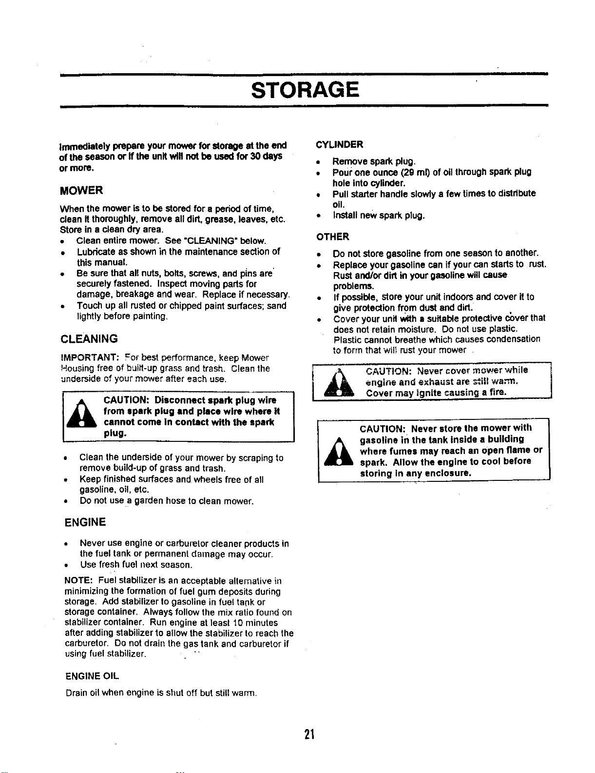
STORAGE
Immediately prepare yourmower for storageat the end
of the season or ffthe unitwill not he used for 30 days
or more.
MOWER
When the mower isto be stored for a periodof time,
clean Itthoroughly,remove all dirt, grease, leaves, etc.
Store in a clean dry area.
• Clean entiremower. See "CLEANING"below.
• Lubricateas shownin the maintenancesectionof
this manual.
• Be sure that all nuts,bolts, screws,and p[nsare"
securelyfastened. Inspectmovingparts for
damage, breakage and wear. Replace if necessary.
• Touch up all rustedor chipped paintsurfaces;sand
lightlybefore painting,
CLEANING
mMPORTANT: =or bestperformance, keep Mower
Housing free ofbuilt-up grassand trash. Cleanthe
underside of your mower after each use.
I_IL CAUTION: Disconnect spark plug wire
from spark plug end place wire where it
cannot come in contact with the spark
plug.
• Clean the underside of your mower by scrapingto
remove build-up ofgrass and trash.
• Keep finishedsurfacesand wheels free of all
gasoline, oi!,etc.
• Do not usea garden hoseto clean mower.
ENGINE
• Never use engine or carburetorcleaner products in
thefuel tank or permanent damage may occur.
• Use fresh fuel nextseason.
NOTE: Fuel stabilizer isan acceptablealternative in
minimizing the formation of fuel gum deposits during
storage, Add stabilizer to gasolinein fuel ta(_kor
storage container. Always follow the mix ratio found on
stabilizer container. Run engine at least 10 minutes
after addingstabilizerto allowthe stabilizer to reach the
carburetor. Do not drain the gas tank and carburetor if
using fuel stabilizer.
ENGINE OIL
Drain oilwhen engine isshut off but stillwarm.
CYLINDER
• Remove spark plug.
• Pourone ounce (29 ml) of oilthroughspark plug
hole intocylinder.
• Pull starter handle slowlya few times to distribute
oil.
• Installnew spark plug.
OTHER
• Do not store gasolinefrom one seasonto another.
• Replace yourgasoline can if yourcan startsto rust.
Rust and/ordirt in yourgasolinewillcause
problems.
• If possible,store your unitindoorsand cover itto
give protectionfrom dust and dirt.
• Cover yourunitwith a suitable protectivecover that
does not retain moisture. Do not use plastic.
Plastic cannotbreathe which causes condensation
to form that will rust your mower
t _ CAUTION: Never cover mowerwhile i
i engine and exhaust are still warm.
Cover may ignite causing a fire.
CAUTION: Never store the mower with
_L asoline ifi the tank inside a building
where fumes may reach an Open flame or
spark. Allow the engine to cool before
storing In any enclosure.
21
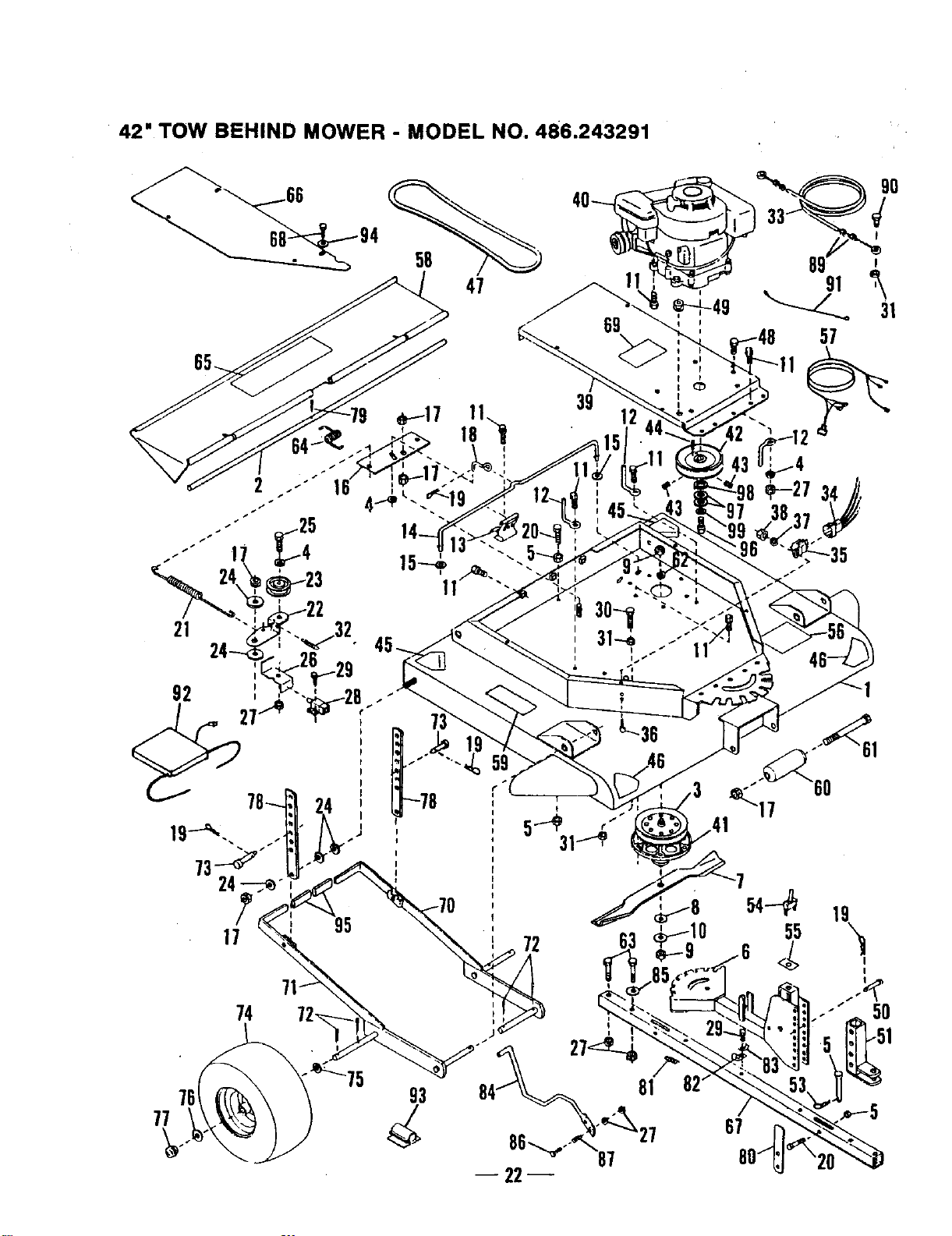
42" TOW BEHIND MOWER - MODEL NO. 486.243291
58
47
39
21
0
89
91 ,_
31
57
67

42" TOW BEHIND MOWER - MODEL NO. 486.243291
Item _,/. Item Qty.
No. Part No. Description Req. No, Part No. Description Req.
1. HA23834
2. HA23596
3. HA23343
4. HA446363"
5. 43064*
6. HA23519
7. HA23516
8. HA23246
9, HA124634*
10. HA20129
11. HA23193
12. HA22951
13. HA2.3194
14. HA22987
15. HA120359
16. HA23518
17. 43262*
18. HA2.2948
19. HA3430
20. 44180
21. HA23196
22. HA23259
23, l HA15015
24. HA8979
25, 41676"
26. HA23197
27. 43082*
28. HA17322
29. HA9411666*
30, 43648"
31, HA4!19"
32. HA0293
33. 24617
34. HA23253
35. HA23252
36. HA159920*
37. HA120217"
38. HA120361 *
39. HA23513
40. HA240t 0
41 HA23241
42. HA22994
43, HA115321 *
44. HA3073
45. HA17285
46. HA12315
47, HA22980
48, 4300t *
49. HA19464
50. HA23836
51. HA23644
52. HA20986
53, HA3341
54. HA22759
55, HA23262
56. HA23647
57. HA23812
58. HA23597
59. HA23755
60. HA12t 38
61. HA126145"
62, HA120898*
63. 43432*
64. HA12988
65. HA20710
88. HA23645
Mower Deck Pan ........................................ 1
Rod- Deflector Mounting ............................ 1
Pulley .......................................................... 2
Washer, 3/8" x 7/8' x .08". ......................... 3
Nut- 5/16-18 Hex Lock .............................. 4
Hitch Assembly ........................................... 1
Mower Bade ...................................... 2
SallevilleWasher ........................................ 2
Nut, 9/16-15 Hax ........................................ 4
Flat Washer ................................................ 2
Screw, 3/8-16 x 1-1/4 Thread Forming ..,. 25
Belt Guide ................................................... 3
Brake Spr ng Assembly ............................. 2
Brake Rod ................................................... 1
Washer, 1/2" x I-1/4" x .08'3 ..................... 2
C_utchSeltcrank ......................................... I
Nut, 1/2-13 Hex Lock ................................. 6
Brake Release Rod .................................... 1
Hair Cotter Pin ............................................ 5
Bolt, 5/16.18 x 2" Hex Head Grade 5........ 3
Idler Tension Spring ................................... 1
Idler Bracket ............................................... 1
Idler Pu ey ........................... 1
Flat Washer ................................................ 5
Bolt, 3/8-16 x 1-3/4 =Hex Head .................. 1
Interlock Bracket......................................... 1
Nut, 3/8-16 Hex Lock ................................. 4
Interlock Swffch .......................................... 1
Screw, #10-16 x 1/2" SerfTappin 9 ............. 8
Bolt, 1/4-20 x 1-1/2" Hex Head .................. 1
Nut, 1/4-20 Hex Lock ................................. 4
Extension Spring ........................................ I
Clutch Cable ............................................... 1
Module ConneCtor ...................................... 1
Modu e ......................................... 1
Screw, #10-24 x 1/2" Pan Head ................. 2
Washer, #10 Med. Lock ............................. 2
Nut, #10-24 Hex ......................................... 2
Engine Mountfng Plate ............................... I
8 HP Engine ............................................... 1
SpJtldle Assembly ................................. 2
Pulley .......................................................... 1
Set Screw, 5/16-18 x 5/16" Socket Hd....... 2
Square Key ................................................. 1
Danger Decal.............................................2
Danger Decal.............................................2
V-Belt .......................................................... 1
Bolt, 3/6-16 x 1"Hex Head ........................ I
Rubber Grommet ........................................ 1
Clays Pn .............................. 2
Towbar Assembly ....................................... 1
Hitch Pin
..................................................... 1
Hair Cotter Pin ............................................ 1
On/Off Switch ............................................. 1
Decal- Engine Shu Off ...................... 1
Clutch Lever Decal ..................................... 1
Wire Harness .............................................. 1
Deflector ..................................................... 1
Decal - Operation ....................................... 1
Mower Roller .............................................. 1
Bolt, 1/2-13 x 7" Hex Head ....................... 1
Washer, 9/16" Lock .................................... 2
Bolt, 3/8-18 x 2-1/2" Hex Head .................. 4
Deflector Spring ......................................... I
Sears Logo Decal ....................................... 1
Salt Cover .....: ............................................. 2
67. HA23525
68. HA15683
69, HA12314
70. HA22996
71. HA22997
72. HA103407
73, HA23638
74. HA24350
75. HA456151
76, HA2.3263
77. HA23229
78. HA23646
79, 44101*
80. HA24441
81. HA20186
82. HA23760
93. HA23761
84. HA23527
85, HA15200
96. 43062*
97. HA19445
89. HA120368"
90. 43012*
91. HA23532
92, HA23586
93. HAl1947
94. 43088
99, 47707
96. HA181666.
97. HA4143
98. 43601
99, HA120389
NP HA24059
Hitch Tube .................................................. 1
Self Tapping Screw.................................... 6
Danger Decal ............................................ 1
Left Hand Wheel Mounting Bracket .......... 1
Right Hand Wheel Mounting Bracket ....... 1
Cotter Pin ................................................... 8
Clevis Pin................................................... 2
Wheel ......................................................... 2
FJatWasher, 13/t S" x 1-1/2"x .134' ......... 2
Flat Washer ............................................... 2
Hub Cap ..................................................... 2
Height Adjustment Strap ........................... 2
Cotter Pin, 3/32" x 3/4". ............................. 1
Strap, L_ch ............................................... 2
Spring, Latch ...................................... ...,... 2
Clip - Hose/Cable 1/2"............................... 6
Clip - Hose/Cable 3/8". .............................. 3
Lever. Clutch ............................................ 1
Washer, 13/32" x 1-3/16" x 3/16 °, ............. 2
Bolt, 3/8-°16 x 1-1J2" Hex Head ................. 1
Spring ........................................................ 1
Nut, 5/15-24 Hex ....................................... 4
Bolt, 1/4-20 x 3/4' Hex Head .................... 2
Wire ............................................................ 1
Operator's Presence Seat ......................... 1
Cord Clip .................................................... 2
Washer, 1/4" Std....................................... 4
Grip - Handle ............................................. 2
Bolt, 7/18-20 x 1-1/4' Hex Head ............... 1
Washer, l"x 13/16" Thick ......................... 2
Washer, 1.59" x 1,032" x .06" ................... 1
Washer, 1/2=x 1-1/4" x ,083". ................... 3
Manual - Operator's
*Standard Hardware - Purchased Locally.
23
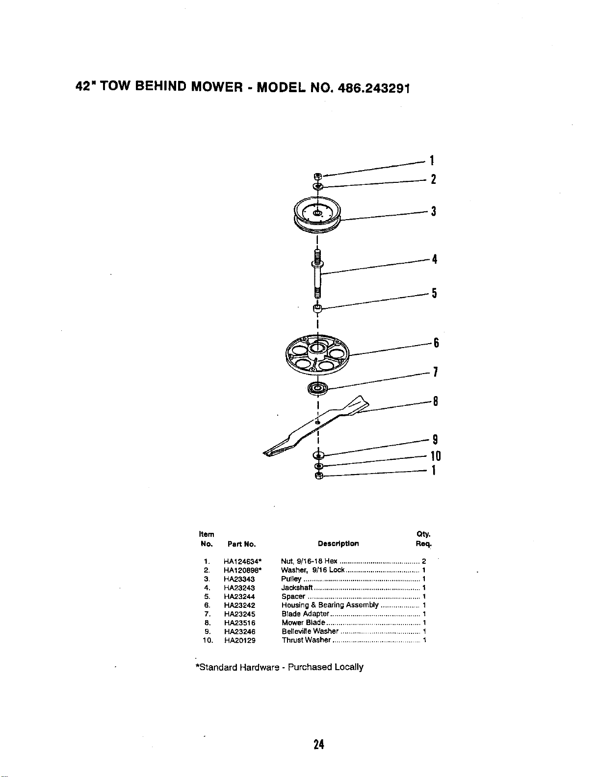
42" TOW BEHIND MOWER - MODEL NO. 486.243291
I
j5
• i 8
Item Qty,
No. Part NO. Description Req.
1. HA124634*
2. HA120898"
3. HA23343
4. HA23243
5. HA23244
6, HA23242
7. HA23245
8, HA23516
9, HA23246
10. HA20129
Nut, 9/16-18 Hex ....................................... 2
Washer, 9/16 Lock.................................... 1
Pulley ......................................................... 1
Jacksheft .................................................... 1
Spacer ....................................................... 1
Housing & Searing Assembly ................... 1
Blade Adapter ............................................ 1
Mower Blade .............................................. 1
BellevilleWasher .......................................I
ThrustWasher ...........................................I
*Standard Hardwar9 - Purchased Locally
24
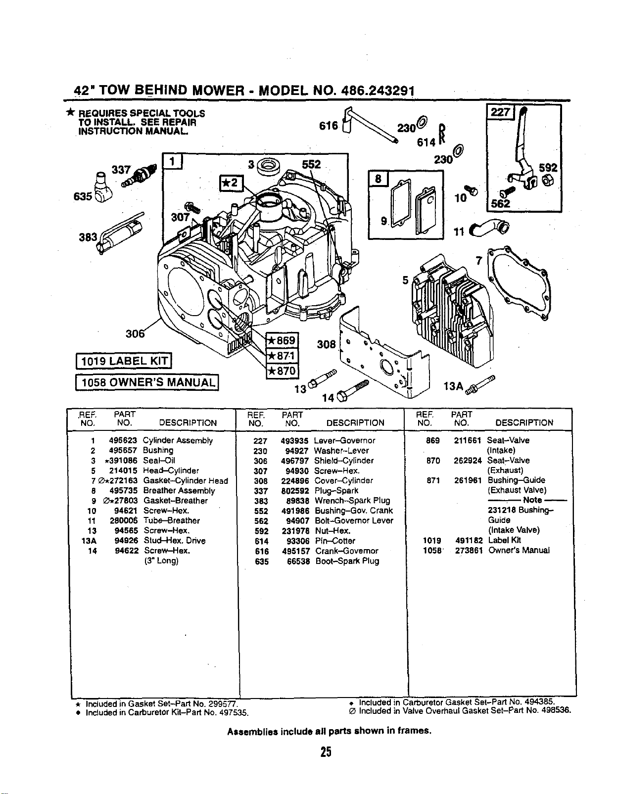
42" TOW BEHIND MOWER - MODEL NO. 486.243291
l_r REQUIRES SPECIAL TOOLS
TO INSTALL. SEE REPAIR
INSTRUCTION MANUAL
635_ ¸
11019 LABEL KIT I
11058OWNER'S"ANUALI
3
230 _)
mm
10_ 562
13J 13,
.REF. PART REF. PART PART
NO, NO. DESCRIPTION NO. NO. DESCRIPTION NO. DESCRIPTION
1 495623 Cylinder Assembly
2 495657 Bushing
3 *391086 Seal-Oil
5 214015 Head--Cylinder
7 _Z'-272163 Gasket-Cylinder Head
8 495735 Breather Assembly
9 _,_27803 Gasket-Breather
10 94621 Screw-Hex.
11 280005 Tube-Breather
13 94565 Screw-Hex.
13A 94926 Stud-Hex. Ddve
14 94622 Screw-Hex.
(3" Long)
227 493935 Lever-Governor
230 94927 Washer-Lever
306 496797 Shield-Cylinder
307 94930 Screw-Hex.
308 224896 Cover-.Cylinder
337 802592 Plug--Spark
383 89838 Wrench-Spark Plug
552 491986 Bushing-Gov. Crank
562 94907 Bolt-Governor Lever
592 231978 Nut-Hex.
614 93306 Pin-Cotter
616 495157 Crank--Governor
635 66538 Boot-Spark Plug
REF.
NO.
869
870
871
1019
1058
211661 Seat-Valve
(Intake)
262924 Seat-Valve
(Exhaust)
261961 Bushing--Guide
(Exhaust Valve)
Note
231218 Bushing-
Guide
(Intake Valve)
491182 Label Kit
273861 Owner's Manual
* Included in Gasket Set-Part No. 299577. 4. Included in Carburetor Gasket Set-Part No. 494385.
• Includedin Carburetor Kit-Part No. 497535. O Includedin Valve Overhaul Gasket Set-Part No, 498536.
Assemblies include all parts shown in frames,
25
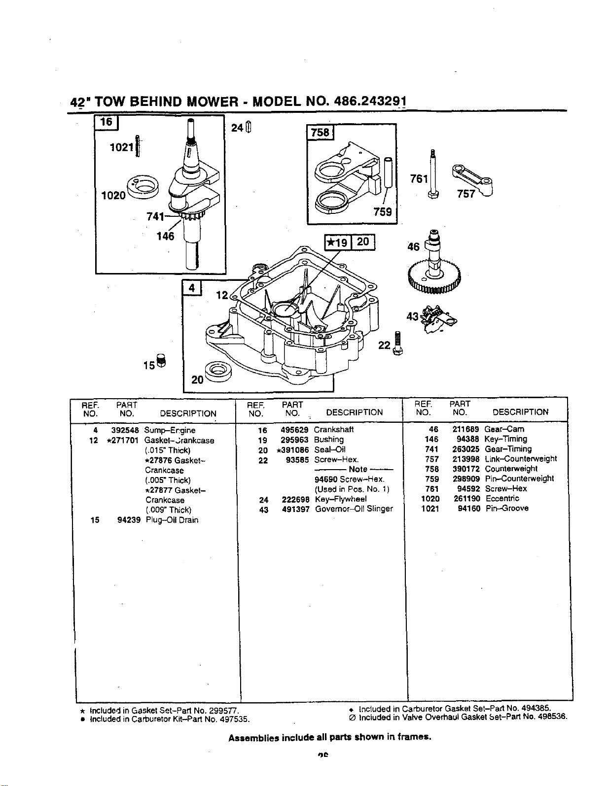
4_2"TOW BEHIND MOWER - MODEL NO. 486.243291_
741_--_ 759
REE PART
NO. NO. DESCRIPTION
4 392548 Sump-Er':gine
12 *271701 Gasket-,Srankcase
(.015" Thick)
*27876 Gasket-
Crankcase
(.005* Thick)
*27877 Gasket-
Crankcase
(,009" Thick)
15 94239 Plug-Oil Drain
RE,=. PART REE PART
NO. NO. DESCRIPTION NO. NO. DESCRIPTION
16 495629 Crankshaft
19 295963 Bushing
20 *391086 Seal-Oil
22 93585 Screw-Hex,
Note --
94690 Screw-Hex,
(Used in Pos. No. 1)
24 222698 Key-Flywheel
43 491397 Governor_il Slinger
46 211689 Gear-Cam
146 94388 Key-Timing
741 263025 Gear-Timing
767 213996 Link-Counterweight
758 390172 Counterweight
759 298909 Pin-Counterweight
761 94592 Screw-Hex
1020 261190 Eccentric
1021 94160 Pin-.Groove
* Included in Gasket Set-Part No. 299577. _. Included in Carburetor Gasket Set-Part No. 494385.
• Inctuded in Carburetor Kit-Part No. 497535. O Included in Valve Overhaul Gasket Set-Part No. 498536.
Assemblies include all parts shown in frames.
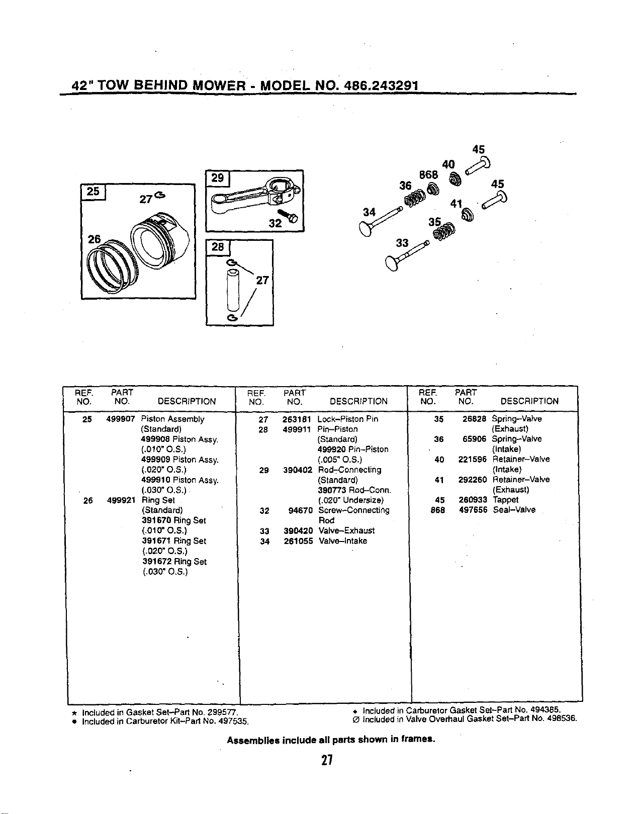
42" TOW BEHIND MOWER - MODEL NO. 486.243291
I
!J
45
4O
868 _ _
34 35
REF. PART REF. PART PART
NO. NO. DESCRIPTION NO, NO. DESCRiPTiON NO. DESCRIPTION
25 499907
26 499921
Piston Assembly
(Standard)
499908 Piston Assy.
(.010" O.S.)
499909 Piston Assy.
(.020"O.S,)
499910 Piston Assy.
(.030"O.S.)
Ring Set
(Standard)
391670 Ring Set
(.010" O.S.)
391671 Ring Set
(.020" O.S.)
391672 Ring Set
(.030" O.S.)
27 263161
28 499911
29 390462
32 94670
33 390420
34 261055
Lock-Piston Pin
Pin-Piston
(Standard)
499920 Pin-Piston
(.005" O.S.)
Rod-:-Connecting
(Standard)
390773 Rod-Conn.
(.020" Undersize)
Screw-Connecting
Rod
Valve-Exhaust
Valve-Intake
REF.
NO.
35 26828 Spr_ng-Valve
(Exhaust)
36 65906 Spring--Valve
(Intake)
40 221596 Retainer-Valve
(Intake)
41 292260 Retainer-Valve
(Exhaust)
45 260933 Tappet
868 497656 Seal-Valve
* Included in Gasket Set-Part No. 299577. , Included inCarburetor Gasket Set-Part No. 494385.
Included in Carburetor Kit-Part No. 497535. O Included in Valve Overhaul Gasket Set-Part No. 498536.
Assemblies include all parts shown in frames.
27
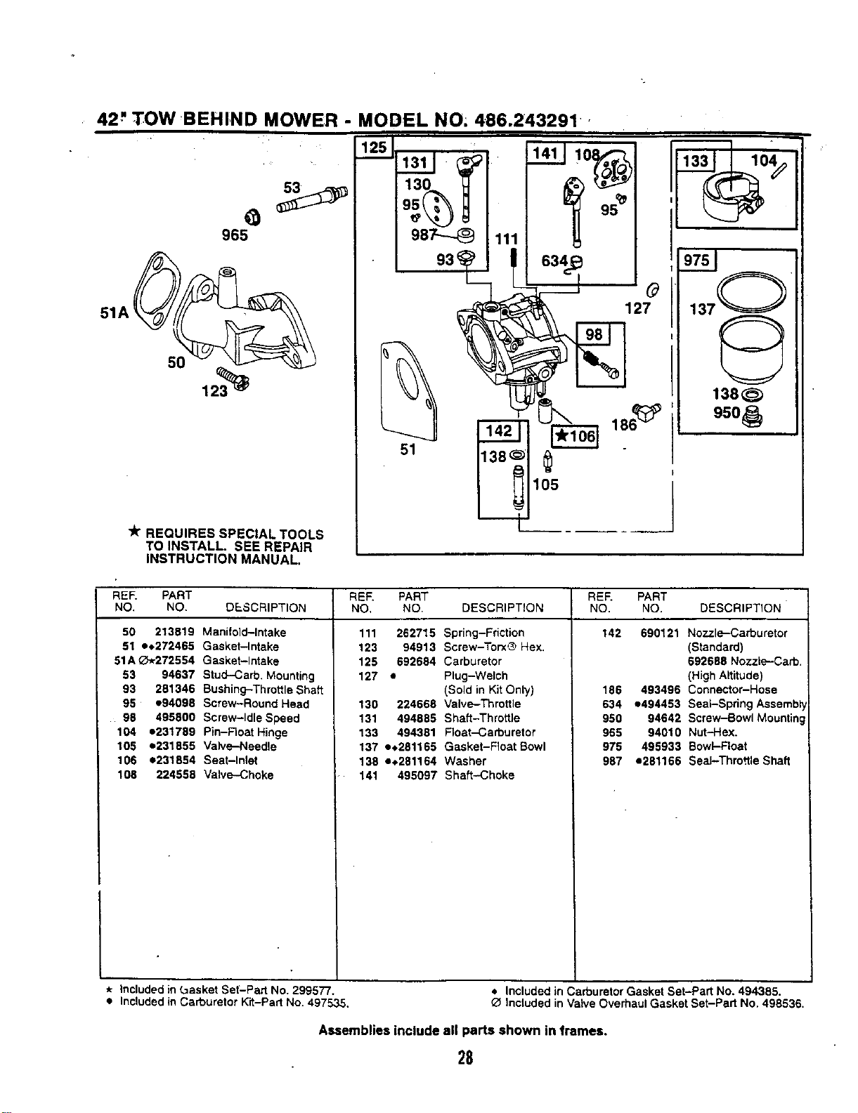
42" TOW BEHIND MOWER - MODEL NO. 486.243291,
5O
"k" REQUIRES SPECIAL TOOLS
TO INSTALL. SEE REPAIR
INSTRUCTION MANUAL.
950_
REF. PART REF. PART REF. PART
NO. NO. DESCRIPTION NO, NO. DESCRIPTION NO. NO. DESCRIPTION
50 213819 Manifold-Intake
51 h272465 Gasket-Intake
51A _-_272554 Gasket-Intake
53 94637 Stud-Carb. Mounting
93 281346 Bushing-Throttle Shaft
95 e94098 Screw-Round Head
98 495800 Screw-Idle Speed
104 =231759 Pin-Roar Hinge
105 e231855 Valve-Needle
106 e231854 Seat-Inlet
108 224559 Valve-Choke
111 262715 Spring-Friction
123 94913 Screw-Torx'_ Hex.
125 692684 Carburetor
127 • Plug-Welch
(Sold in Kit Only)
139 224668 Valve-Throttle
131 494885 Shaft-Throttle
133 494381 Float-Carburetor
137 e•281165 Gasket-Float Bowl
138 e,_281164 Washer
141 495097 Shaft-Choke
142 690121 Nozzle-Carburetor
(Standard)
692688 Nozzle-Carb.
(High Altitude)
186 493496 Connector-Hose
634 e494453 Seal-Spring Assembl
950 94642 Screw-Bowl Mounting
965 94010 Nut-Hex.
975 495933 Bowl-Float
987 ,281166 Seal-Throttle Shaft
* Included in L=asket Set-Part No. 299577.
• Included in Carburetor Kit-Part No. 497535.
• Included in Carburetor Gasket Set-Part No. 494385.
Included in Valve Overhaul Gasket Set-Part No. 498536.
Assemblies include all parts shown in frames.
28
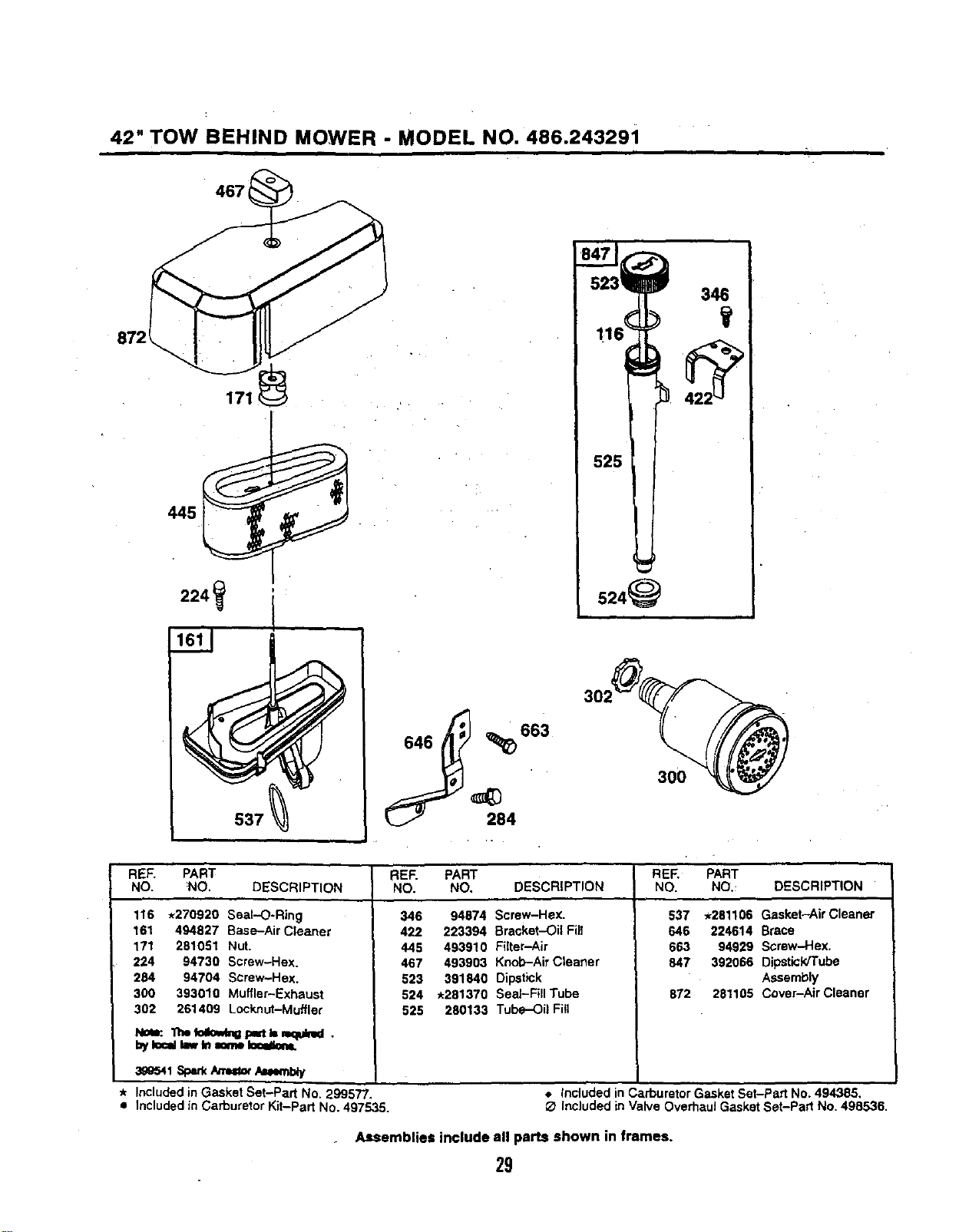
42" TOW BEHIND MOWER - MODEL NO. 486.243291
467
171
j 683
346
524_
REF. PART REF. PART REF, PART
NO. NO. DESCRIPTION NO. NO. DESCRIPTION NO. NO._ DESCRIPTION
116 *270920 Seal-O-Ring
161 494827 Base-Air Cleaner
171 281051 Nut.
224 94730 Screw-Hex.
284 94704 Screw-Hex.
300 393010 Muffler-Exhaust
302 261409 Locknut-Muffler
w,=feco,,,,,,_p=t _-,=quid.
byIo=dI_,,Inminelecalem.
3_eS4t,S_*/re=or/_muy
IncludedinGasketSet-PartNo.299577.
IncludedinCarburetorKit-PartNo.497535.
346 94874 Screw-Hex.
422 223394 Bracket--Oil Fill
445 493910 Filter-Air
467 493903 Knob-Air Cleaner
523 391840 Dipstick
524 *281370 Seal-Fill Tube
525 280133 Tube-Oil Fitl
537 ,_281106 Gasket-Air Cleaner
646 224614 Brace
663 94929 Screw-Hex.
847 392066 DipsticWTube
Assembly
872 281105 Cover-Air Cleaner
• Included in CarburetorGasketSet-Part No, 494385,
O Included in Valve Overbaul GasketSet-Part No. 498536.
Assemblies include all parts shown in frames.
29
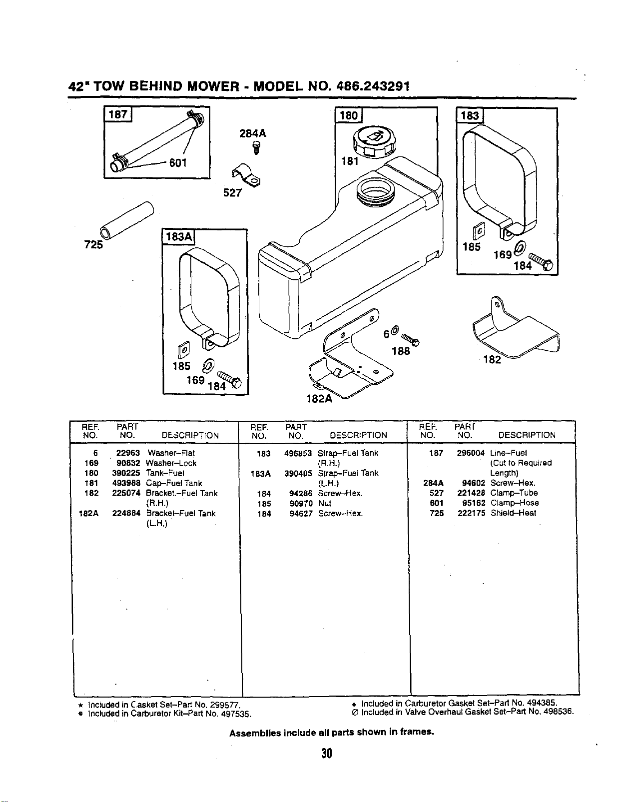
42" TOW BEHIND MOWER - MODEL NO. 486.243291
725
284A
185
169 184_
188
REF. PART REF. PART
NO. NO. DESCRIPTION NO. NO. DESCRIPTION
6 22963 Washer-Flat 183 496853 Strap-Fuel Tank
169 90832 Washer-Lock (R.H.)
180 390225 Tank-Fuel 183A 390405 Strap-PuaITank
181 493988 Cap-Fuel Tank (L.H,)
182 225074 Sracket.-Fuel Tank 184 94296 Screw-Hex.
(R,H,) 185 90970 Nut
182A 224884 Bracket-Fuel Tank 184 94627 Screw-Hex,
(L.H.)
REF. PART
NO. NO. DESCRIPTION
187 296004 Line-Fuel
(Cut to Required
Length)
284A 94602 Screw-Hex.
527 221429 Clamp-Tube
601 95162 Clamp-Hose
725 222175 Shield-Heat
* Included in Casket Set-Part No. 299577. _. Included in Carburetor Gasket Set-Pad No. 494385.
e Included in Carburetor Kit-Part No. 497535. _ Included in Valve Overhaul Gasket Set-Part No, 498536.
Assemblies include all parts shown in frames.
3O
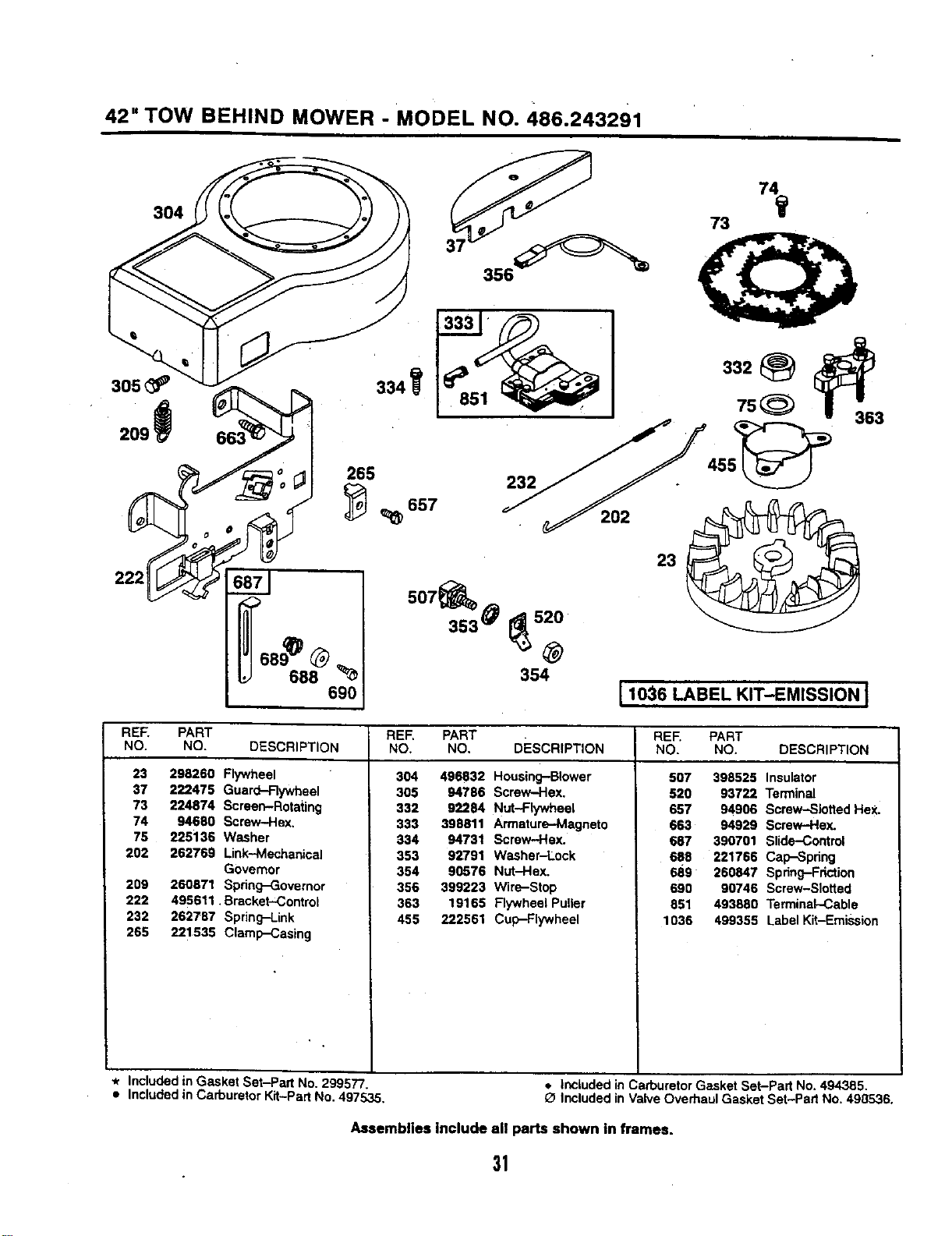
42" TOW BEHIND MOWER - MODEL NO. 486.243291
3O4
305 _ 334
222
265
232
354
[ 1036 LABEL KIT-EMISSION [
RER PART
NO. NO. DESCRIPTION
23 298260 Flywheel
37 222475 Guard-Rywheel
73 224874 Screen-Rotating
74 94680 Screw-Hex,
75 225136 Washer
202 262769 Link-Mechanical
Governor
209 260971 Spring-Governor
222 495611, Bracket-Control
232 262787 Spring-Link
265 221535 Clamp-Casing
* Included in Gasket Set-Pad No. 299577
• Included in Carburetor Kit-Part No. 49753_.
REF. PART
NO, NO. DEscRIPTION
304 496832 Housing-Blower
305 94786 Screw-Hex.
332 92284 Nut-Flywheel
333 398811 Armature-Magneto
334 94731 Screw-Hax.
353 92791 Washer-Lock
354 90576 Nut-Hex.
356 399223 Wire-Stop
363 19165 Flywheel Puller
455 222561 Cup-Flywheel
REF. PART
NO. NO, DESCRIPTION
507 398525 Insulator
520 93722 Terminal
657 94906 Screw-Slotted Hex.
663 94929 Screw-Hex.
687 390701 Slide-Control
688 221766 Cap-Spring
689 260847 Spring-Friction
690 90746 Screw-Slotted
851 493880 Terminal-Cable
1036 499355 Label Kit-Emission
• Included in Carburetor Gasket Set-Part No. 494385.
Included in ValveOverhaul Gasket Set-Pad No. 498536.
Assemblies Include all parts shown in frames.
31
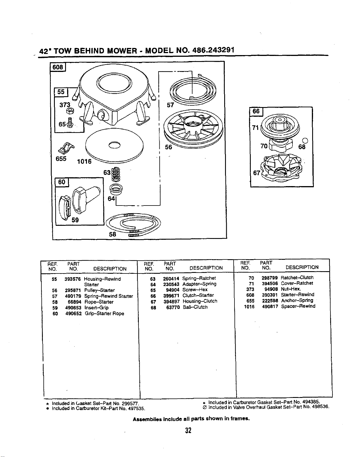
42" TOW BEHIND MOWER - MODEL NO. 486.243291
608 _ _
655 1016 _ " "
REE PART
NO. NO. DESCRIPTION
55 393576 Housing-Rewind
Starter
56 295871 Pulley,-Starter
57 490179 Spring-Rewind Starter
58 66094 Rope--Starter
59 490653 Insert-,Grip
60 490652 Grip-Starter Rope
REE PART REE PART
NO. NO. DESCRIPTION NO. NO. DESCRIPTION
63 260414 Spring-Ratchet 70 298799 Ratchet-Clutch
64 230543 Adapter-Spring 71 394506 Cover-Ratchet
65 94904 Screw-Hex 373 94908 Nut-Hex.
66 399671 Clutch-Starter 608 390391 Starter-Rewind
67 394807 Housing-Clutch 655 222598 Anchor-Spring
68 63770 Bait--Clutch 1016 490817 Spacer-Rewind
* Included in Gasket Set-Part No. 299577. *, Included in Carburetor Gasket Set-part No. 494385.
• included in Carburetor Kit-Part No. 497535. _ Included in Valve Overhaul Gasket Set-Part No. 498536.
Assemblies include all parts shown in frames.
32
42" TOW BEHIND MOWER - MODEL NO. 486.243291
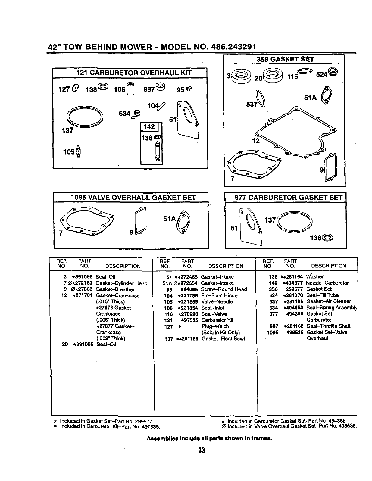
iii
121 CARBURETOR OVERHAUL KIT
127_ 138 _ 106(_ 987_ 95_
137_ _ 634_.._ 104_ 51_
1os
358 GASKET SET
3_ 20_ 116_' 524_)
537_ 51A_
1095 VALVE OVERHAUL GASKET SET
I 977 CARBURETOR GASKET SET
137 0
51 135
REF. PART REF. PART REF. PART
NO, NO. DESCRIPTION NO. NO. DESCRIPTION NO. NO, DESCRIPTION
3 *391086 Seal-Oil
70*272163 Gasket--Cylinder Head
9 O.27803 Gasket-Breather
12 *271701 Gasket-Crankcase
(.015" Thick)
*27676 Gaaket-
Crankcase
(.005"Thick)
*27877 Gasket-
Crankcase
(.009" Thick)
20 *391086 Seal-Oil
51 e,_272465 Gasket-Intake
51A _.272554 Gasket-Intake
95 e94098 Screw-Round Head
104 e231789 Pin-Roat Hinge
105 1231855 Valve--Needle
106 o231854 Seat-Inlet
116 *270920 Seal-Valve
121 497535 Carburetor Kit
127 • Plug--Welch
(Soldin KitOnly)
137 e_,281165 Gasket-Float Bowl
138 e.261164 washer
142 e494877 Nozzl_uretor
358 299577 Gasket Set
524 .281370 SeaJ-FillTube
537 .261106 Gasket-Air Cleaner
634 e494453 Seal-Spring Assembl,
977 494365 Gasket Set-
Carburetor
987 *261166 Seal-Threttle Shaft
1095 "498536 GasketSet-Valve
Overhaul
* Includedin Gasket Set-Part No. 299577.
• Includedin CarburetorKit-Part No. 497535.
Included in CarburetorGasket Set-Part No. 494385.
Included in Valve Overhaul Gasket Sat-Part No. 498536.
Assemblies Include all parts shown in frames,
33

34

35

Forthe repair orreplacementparts youneed
delivered directlyto yourhome
Call7 am - 7 pro, 7 days a week
1-800-366-PART
(1-800-366-7278)
Forin-homemajorbrandrepairservice
Call24 hours a day,7 daysa week
1-800-4-REPAIR
(1-800-473-7247)
F_)rthelocationofa
SearsPartsandRepairCenterinyourarea
Ca',',24 hours a day,7 daysa week
1-800-488-1222
|iN|BI
mmmmmmj
Forinformationonpurchasinga Sears
Maintenance Agreementor to inquire
aboutan existingAgreement
call 9 am - 5 pm, Monday-Saturday
1-800-827-6655
SEARS
America'sRepairSpecla#sts FORM NO. HA24059 (REV. 2/00)