Loading ...
Loading ...
Loading ...
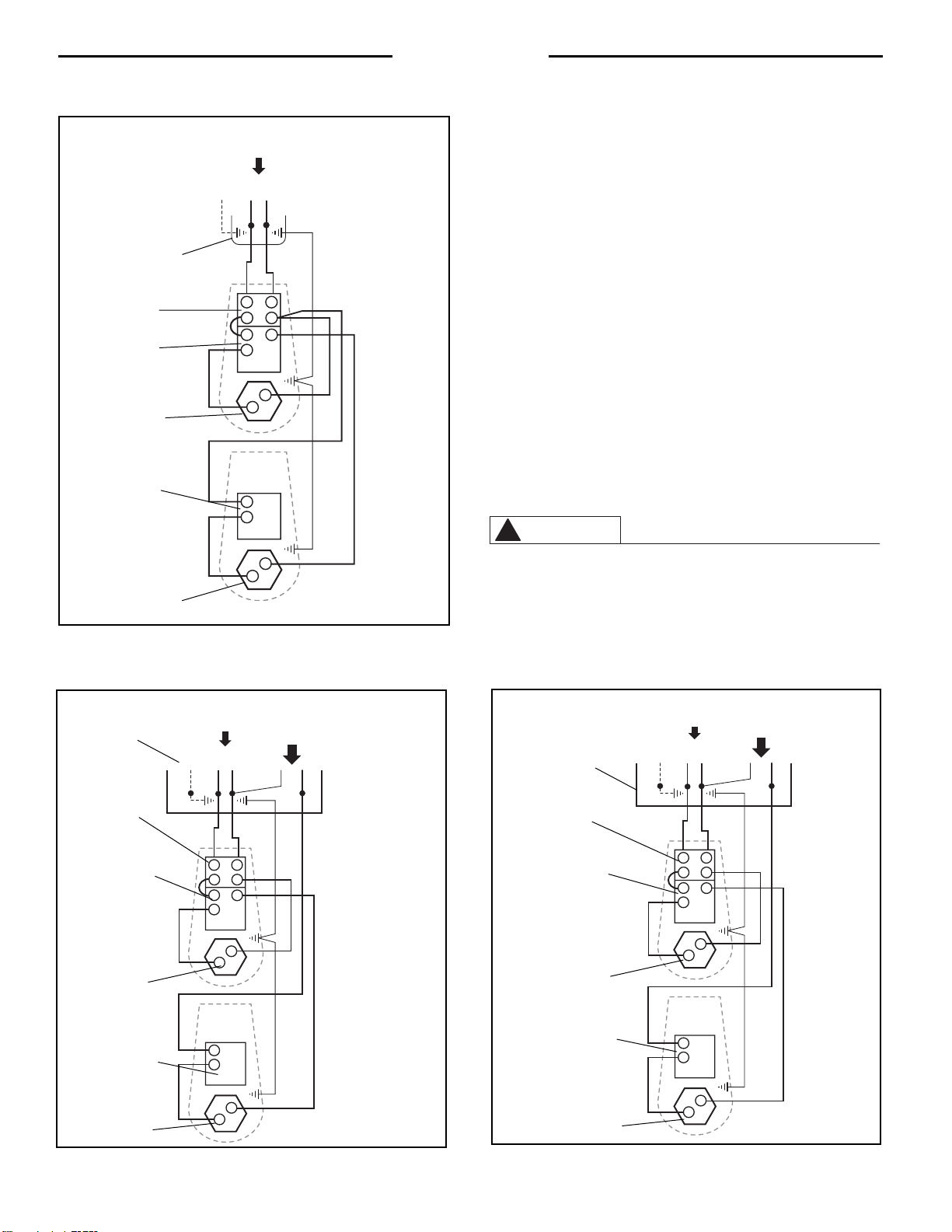
The complete wiring schematic diagram for standard non-
simultaneous operation units is shown below in Figure 6.
power supply provided is equivalent to that marked on the water heater’s
rating plate. All wiring must conform to local codes or, in the absence of
local codes, the latest edition of National Electrical Code ANSI/NFPA 70.
The Specification Table (supplied separately with the water heater) recom-
mends minimum branch circuit sizing based on National Electric Code.
The branch circuit wiring must include either:
A. Metallic conduit or metallic sheathed cable approved for use as a
grounding conductor and installed with fittings approved for the pur-
pose. (refer to Figure 5A)
B. Non-metallic sheathed cable or metallic conduit or metallic sheathed
cable not approved for use as a ground conductor shall include a
separate conductor for grounding. It should be attached to the ground
terminals of the water heater and the electrical distribution box. (Refer
to Fig. 5B)
Be sure to follow local and national codes as well as any electric utility
requirements when making the connections.
CONNECTING THE WATER HEATER TO A TIME SWITCH OR OFF-
PEAK METER — In some installations it may be desired or required by
local utility regulations to connect the water heater to a Time Switch or Off-
Peak Meter. Refer to Figure 7 or 8 below for complete wiring schematic
diagram for standard non-simultaneous operation units installed in con-
junction with these energy management devices.
Connecting the water heater to a Time Switch or Off-Peak Meter
requires splicing or complete replacement of internal wiring. For
this reason, it is strongly recommended that this work be per-
formed by a licensed electrician, qualified appliance service per-
son, or utility company representative.
IMPORTANT!! — When connecting the water heater to a Time
Switch or Off-Peak Meter, the Black wire from Terminal No. 4 of the
6
Installation
Figure 8 — Complete Wiring Schematic Diagram — Non-Simul-
taneous Operation on separate Off-Peak Meter.
Figure 7 — Complete Wiring Schematic Diagram — Non-Simulta-
neous Operation on separate Time Switch.
WARNING
!
RED
BLACK
BLACK
BLACK
GROUND
RED
1
2
1
2
1
2
3
4
4
RED
YELLOWYELLOW
BLUE
From 240 V
Power Source
Water Heater
Junction Box
High Limit
Switch
Upper
Temperature Control
Thermostat
Upper Element
Lower
Temperature Control
Thermostat
Lower Element
RED
BLACK
BLACK
BLACK
GROUND
RED
1
2
1
2
1
2
3
4
4
RED
YELLOW
YELLOW
BLUE
From 240 V
Power Source
From Time Clock Switch
Water Heater
Junction Box
High Limit
Switch
Upper
Temperature Control
Thermostat
Upper Element
Lower
Temperature Control
Thermostat
Lower Element
Figure 6 — Complete Wiring Schematic Diagram —Standard
Non-Simultaneous Operation.
From 240 V
Power Source
From Off Peak Meter
Water Heater
Junction Box
High Limit
Switch
Upper
Temperature Control
Thermostat
Upper Element
Lower
Temperature Control
Thermostat
Lower Element
RED
BLACK
BLACK
BLACK
GROUND
RED
1
2
1
2
1
2
3
4
4
RED
YELLOW
YELLOW
BLUE
Loading ...
Loading ...
Loading ...