Loading ...
Loading ...
Loading ...
3. WATER SUPPLY CONNECTIONS — Refer to Fig. 2 for suggested typi-
cal installation. The installation of unions or flexible copper connectors is
recommended on the hot and cold water connections so that the water
heater may be easily disconnected for servicing if necessary. The HOT
and COLD water connections are clearly marked and are 3/4” NPT on all
models. Install a shut-off valve in the cold water line near the water heater.
NOTE: If the incoming water pressure is over 80 PSI, be sure to
install a pressure reducing valve (water pressure regulator)
somewhere in the inlet water line upstream of the water heater.
COLD WATER SUPPLY LINE TO HEATER — The cold water inlet has a
factory installed vacuum relief valve in it. (Refer to Figure 2) Certain condi-
tions, such as a break in the main water supply line, pump failure on a well
system or other plumbing system malfunctions could produce a vacuum or
negative pressure in the water heater’s tank. The vacuum relief valve pro-
vides a means to eliminate the negative pressure or vacuum in the event
of such a failure by admitting air into the tank to equalize the pressure.
NOTE: DO NOT remove the vacuum valve for any reason.
Doing so will void the manufacturer’s warranty!
Run the cold water supply line to the top of the vacuum valve using the pip-
ing of choice for this installation as shown in Figure 2 Be sure to install a
shut-off valve (not supplied with the heater) in the cold water line near the
water heater.
IMPORTANT!! Do not apply heat directly to the vacuum valve
connection. If sweat connections are used, sweat tubing to
adapter before fitting adapter to vacuum valve on heater. Any
heat applied to the vacuum relief valve and cold water fittings
will permanently damage them and/or the tank.
The connection between the vacuum valve and the water heater uses a
seal ring. If unions are not used on the water supply lines, the vacuum
valve can be removed from the heater to accommodate final connection to
supply piping. The hex union fitting on the water heater can then be used
to make the connection between the tank and the valve/supply piping.
Remember to use the seal ring provided with the heater when re-installing
the vacuum valve and water inlet piping. DO NOT use pipe sealant on this
joint!
IMPORTANT! – DO NOT attempt to turn the pipe or fittings after
the hex union nuts are tightened.
Doing so will damage the
water heater beyond repair!
HOT WATER SUPPLY LINE FROM WATER HEATER— The hot water
outlet has a factory installed extension fitting. Run the hot water supply line
to the top of the extension fitting using the piping of choice for this installa-
tion as shown in Figure 2.
IMPORTANT! – Do not apply heat directly to the extension fit-
ting. If sweat connections are used, sweat tubing to adapter
before fitting adapter to extension fitting on heater. Any heat
applied to the extension fitting and hot water fittings will perma-
nently damage them and/or the tank.
The connection between the extension fitting and the water heater uses a
seal ring. If unions are not used on the water supply lines, the extension
fitting can be removed from the heater to accommodate final connection to
hot water supply piping. The hex union fitting on the water heater can then
be used to make the connection between the tank and the piping system.
Remember to use the seal ring provided with the heater when re-installing
the vacuum relief valve and water inlet piping. DO NOT use pipe sealant
on this joint!
IMPORTANT! – DO NOT attempt to turn the pipe or extension
piece after the hex union nuts are tightened.
Doing so will dam-
age the water heater beyond repair!
4. RELIEF VALVE — A relief valve is essential for safety and to protect the
water heater. Too high of a temperature and/or pressure could cause the
tank to burst. The relief valve is designed to automatically open if tempera-
ture and/or pressure reaches a pre-determined point (a temperature of
210°F, or pressure of 150 PSI)
A new combination temperature and pressure relief valve, complying with
the Standard for Relief Valves and Automatic Gas Shutoff Devices for Hot
Water Supply Systems, ANSI Z21.22, has been factory installed in the
opening provided and marked for the purpose on the water heater. (Refer
to Figure 2)
DO NOT operate the water heater unless the Temperature and
Pressure relief valve is installed properly and working correctly.
Doing so will result in an unsafe operating condition that can result
in property damage, bodily injury or death!
DRAIN PIPE FROM RELIEF VALVE — Connect the outlet of the relief
valve to a suitable open drain so that the discharge water cannot contact
live electrical parts and to eliminate potential water damage (check Local
Codes regarding Relief Valve discharge methods). Piping used should be
of a type approved for hot water distribution. The discharge line must be no
smaller than the outlet of the valve and must pitch downward from the
valve to allow complete drainage (by gravity) of the relief valve and dis-
charge line. The end of the discharge line should not be threaded or con-
cealed and should be protected from freezing. No valve of any type,
restriction or reducer coupling should be installed in the discharge line.
Following all of the above rules, install the drain valve discharge piping,
using thread sealer on all male threads.
IMPORTANT!! Do not apply heat directly to the relief valve con-
nection. If sweat connections are used, sweat tubing to adapter
before fitting adapter to relief valve on heater. Any heat applied
to the relief valve will permanently damage it and/or the tank.
4
Installation
WARNING
!
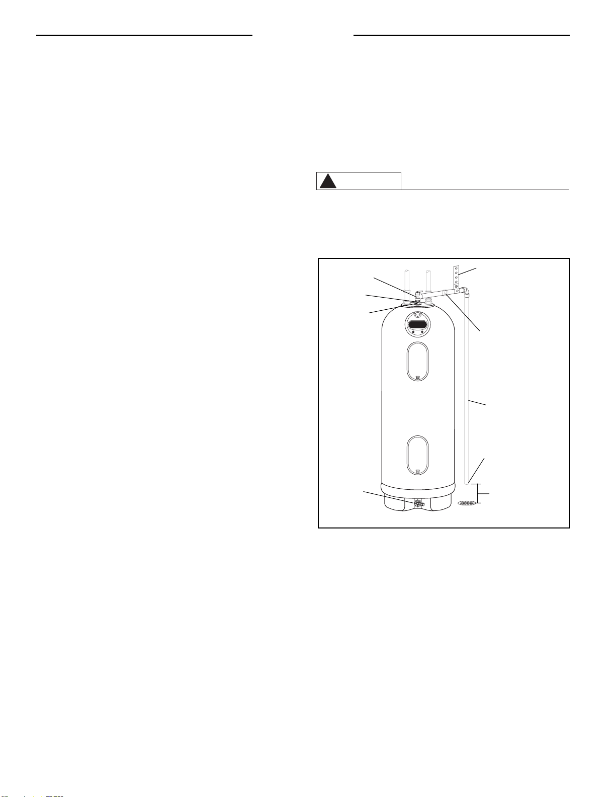
Figure 3 — Typical method of supporting relief valve drain pipe.
Temperature & Pressure
Relief Valve
Union
(The addition of a union at this point will help
in the replacement of the T & P Relief Valve
should the need arise.)
Drain Pipe
Drain Valve
No threads permitted on
end of Drain Pipe.
6” Maximum distance
from drain pipe to suitable
open drain.
Support the relief valve drain pipe
using metal strapping or wire fas-
tened to the structure overhead
Seal Ring
Hex Union Nut
(Relief Valve)
Loading ...
Loading ...
Loading ...