Owner's Manual
JCRHFTSMRN°J
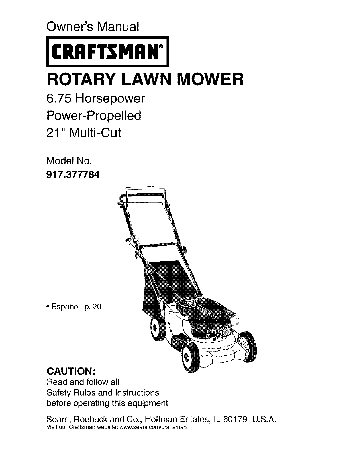
ROTARY LAWN MOWER
6.75 Horsepower
Power-Propelled
21" Multi-Cut
Model No.
917.377784
• EspaSol, p. 20
CAUTION:
Read and follow all
Safety Rules and Instructions
before operating this equipment
Sears, Roebuck and Co., Hoffman Estates, IL 60179 U.S.A.
Visit our Craftsman website: www.sears.com/craftsman
Warranty ................................................... 2
Safety Rules .......................................... 2-4
Product Specifications .............................. 4
Assembly / Pre-Operation ........................ 6
Operation ............................................ 7-11
Maintenance Schedule ........................... 12
Maintenance ...................................... 12-15
Service and Adjustments ................... 15-16
Storage .............................................. 17-18
Troubleshooting ................................. 18-19
Repair Parts ....................................... 38-45
Sears Service .......................... Back Cover
LIMITED TWO YEAR WARRANTY ON CRAFTSMAN POWER MOWER
For two years from date of purchase, when this Craftsman Lawn Mower is maintained,
lubricated, and tuned up according to the operating and maintenance instructions in the
owner's manual, Sears will repair free of charge any defect in material or workmanship.
If this Craftsman Lawn Mower is used for commercial or rental purposes, this warranty
applies for only 90 days from the date of purchase.
This Warranty does not cover:
• Expendable items which become worn during normal use, such as rotary mower
blades, blade adapters, belts, air cleaners and spark plug.
• Repairs necessary because of operator abuse or negligence, including bent crank-
shafts and the failure to maintain the equipment according to the instructions con-
tained in the owner's manual.
Warranty service is available by returning the Craftsman power mower to the nearest
Sears Parts & Repair Center in the United States. This warranty applies only while this
product is used in the United States.
This Warranty gives you specific legal rights, and you may also have other rights which
vary from state to state.
Sears, Roebuck And Co., D/817 WA, Hoffman Estates, Illinois 60179
IMPORTANT: This cutting machine is capable of amputating hands and feet and throw-
ing objects. Failure to observe the following safety instructions could result in serious
injury or death.
_,Look for this symbol to point out
important safety precautions. It means
CAUTION!H BECOME ALERT!H
YOUR SAFETY IS INVOLVED.
&WARNING: In order to prevent ac-
cidental starting when setting up, trans-
porting, adjusting or making repairs,
always disconnect spark plug wire and
place wire where it cannot come in con-
tact with plug.
_:i,WARNING: Battery posts, terminals and
related accessories contain lead and lead
compounds, chemicals known to the State
of California to cause cancer and birth
defects or other reproductive harm. Wash
hands after handling.
_,WARNING: Engine exhaust, some of its
constituents, and certain vehicle compo-
nents contain or emit chemicals known
to the State of California to cause cancer
and birth defects or other reproductive
harm.
2
_, CAUTION: Muffler and other engine
parts become extremely hot during
operation and remain hot after engine has
stopped. To avoid severe burns on contact,
stay away from these areas.
I. GENERAL OPERATION
• Read, understand, and follow all
instructions on the machine and in the
manual(s) before starting. Be thoroughly
familiar with the controls and the proper
use of the machine before starting.
• Do not put hands or feet near or under
rotating parts. Keep clear of the dis-
charge opening at all times.
• Only allow responsible individuals, who
are familiar with the instructions, to
operate the machine.
• Clear the area of objects such as rocks,
toys, wire, bones, sticks, etc., which
could be picked up and thrown by the
blade.
• Be sure the area is clear of other people
before mowing. Stop machine if anyone
enters the area.
• Do not operate the mower when bare-
foot or wearing open sandals. Always
wear substantial foot wear.
• Do not pull mower backwards unless
absolutely necessary. Always look down
and behind before and while moving
backwards.
• Do not operate the mower without
proper guards, plates, grass catcher or
other safety protective devices in place.
• See manufacturer's instructions for
proper operation and installation of
accessories. Only use accessories ap-
proved by the manufacturer.
• Stop the blade(s) when crossing gravel
drives, walks, or roads.
• Stop the engine (motor) whenever you
leave the equipment, before cleaning
the mower or unclogging the chute.
• Shut the engine (motor) off and wait
until the blade comes to complete stop
before removing grass catcher.
• Mow only in daylight or good artificial
light.
• Do not operate the machine while under
the influence of alcohol or drugs.
• Never operate machine in wet grass.
Always be sure of your footing: keep a
firm hold on the handle and walk; never
run.
• Disengage the self-propelled mech-
anism or drive clutch on mowers so
equipped before starting the engine
(motor).
• If the equipment should start to vibrate
abnormally, stop the engine (motor) and
check immediately for the cause. Vibra-
tion is generally a warning of trouble.
• Always wear safety goggles or safety
glasses with side shields when oper-
ating mower.
II. SLOPE OPERATION
Slopes are a major factor related to slip
and fall accidents which can result in
severe injury.All slopes require extra cau-
tion. If you feel uneasy on a slope, do not
mow it.
DO:
• Mow across the face of slopes: never
up and down. Exercise extreme caution
when changing direction on slopes.
• Remove obstacles such as rocks, tree
limbs, etc.
• Watch for holes, ruts, or bumps. Tall
grass can hide obstacles.
DO NOT:
• Do not trim near drop-offs, ditches or
embankments. The operator could lose
footing or balance.
• Do not trim excessively steep slopes.
• Do not mow on wet grass. Reduced foot-
ing could cause slipping.
III. CHILDREN
Tragic accidents can occur if the operator
is not alert to the presence of children.
Children are often attracted to the machine
and the mowing activity. Never assume
that children will remain where you last
saw them.
• Keep children out of the trimming area
and under the watchful care of another
responsible adult.
• Be alert and turn machine off if children
enter the area.
• Before and while walking backwards,
look behind and down for small children.
• Never allow children to operate the ma-
chine.
• Use extra care when approaching blind
corners, shrubs, trees, or other objects
that may obscure vision.
IV. SERVICE
• Use extra care in handling gasoline and
other fuels. They are flammable and
vapors are explosive.
- Use only an approved container.
- Never remove gas cap or add fuel
with the engine running.
Allow engine to cool before refueling.
Do not smoke.
- Never refuel the machine indoors.
- Never store the machine or fuel
container inside where there is an
open flame, such as a water heater.
• Never run a machine inside a closed area.
• Never make adjustments or repairs with
the engine (motor) running. Disconnect the
spark plug wire, and keep the wire away
3 from the plug toprevent accidental starting.
• Keepnutsand bolts,especiallyblade
attachmentbolts,tight andkeepequip-
mentin goodcondition.
• Nevertamperwithsafetydevices.Check
their properoperationregularly.
• Keep machinefree of grass, leaves,or
otherdebrisbuild-up.Cleanoilorfuelspill-
age.Allowmachinetocoolbeforestoring.
• Stopandinspecttheequipmentifyou
strikeanobject.Repair,if necessary,
beforerestarting.
• Neverattempttomakewheelheightadjust-
mentswhiletheengine(motor)isrunning.
• Grasscatchercomponentsaresubject
towear,damage,anddeterioration,
whichcouldexposemovingpartsor
allowobjectsto bethrown.Frequently
checkcomponentsandreplacewith
manufacturer'srecommendedparts,
whennecessary.
• Mowerbladesaresharpandcan cut.
Wraptheblade(s)or weargloves,and
useextracautionwhenservicingthem.
• Donotchangetheenginegovernorset-
tingor overspeedtheengine.
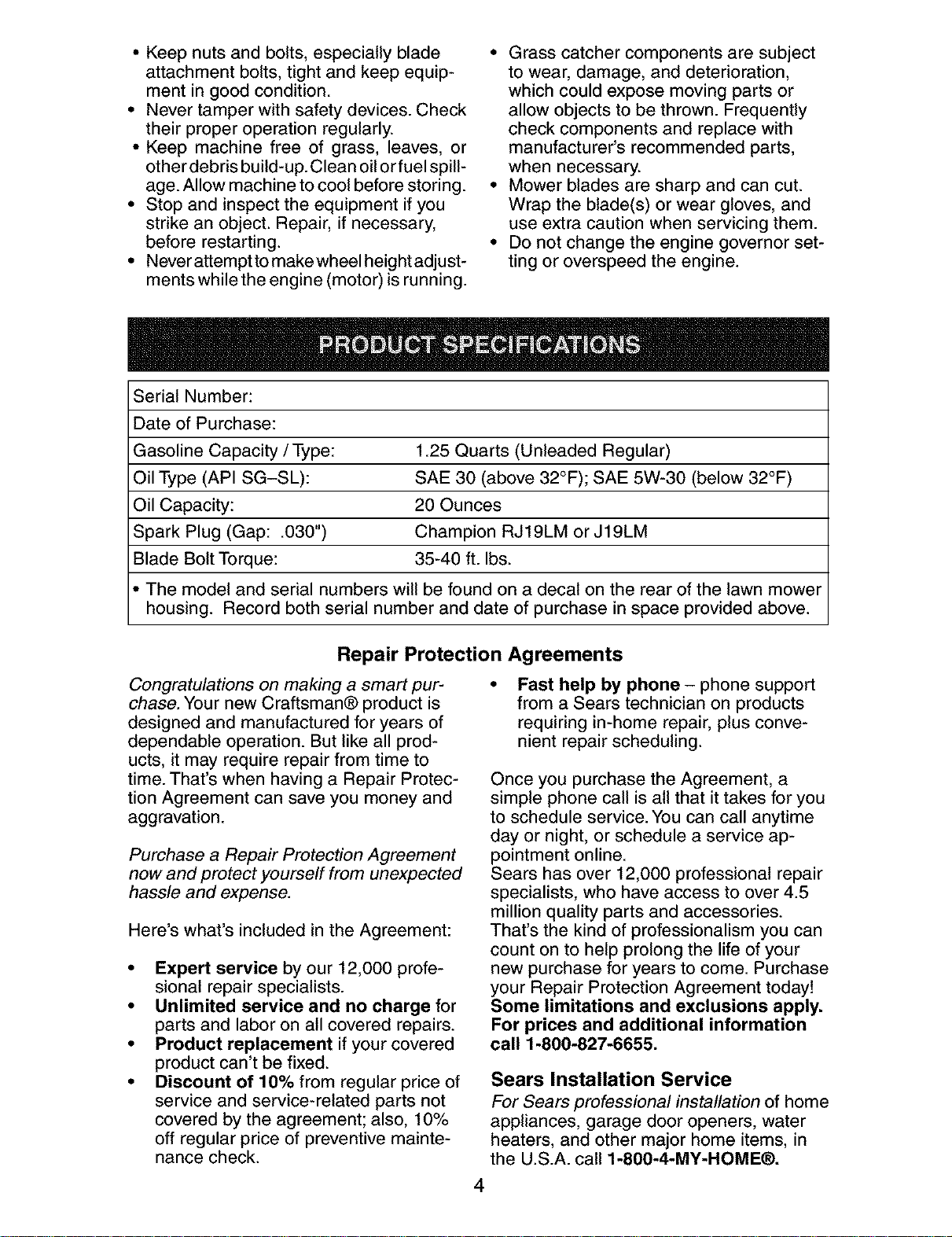
SerialNumber:
Dateof Purchase:
GasolineCapacity/Type: 1.25 Quarts (Unleaded Regular)
Oil Type (API SG-SL): SAE 30 (above 32°F); SAE 5W-30 (below 32°F)
Oil Capacity: 20 Ounces
Spark Plug (Gap: .030") Champion RJ19LM or J19LM
Blade Bolt Torque: 35-40 ft. Ibs.
The model and serial numbers will be found on a decal on the rear of the lawn mower
housing. Record both serial number and date of purchase in space provided above.
Repair Protection Agreements
Congratulations on making a smart pur-
chase. Your new Craftsman® product is
designed and manufactured for years of
dependable operation. But like all prod-
ucts, it may require repair from time to
time. That's when having a Repair Protec-
tion Agreement can save you money and
aggravation.
Purchase a Repair Protection Agreement
now and protect yourself from unexpected
hassle and expense.
Here's what's included in the Agreement:
• Expert service by our 12,000 profe-
sional repair specialists.
• Unlimited service and no charge for
parts and labor on all covered repairs.
• Product replacement if your covered
product can't be fixed.
• Discount of 10% from regular price of
service and service-related parts not
covered by the agreement; also, 10%
off regular price of preventive mainte-
nance check.
Fast help by phone - phone support
from a Sears technician on products
requiring in-home repair, plus conve-
nient repair scheduling.
Once you purchase the Agreement, a
simple phone call is all that it takes for you
to schedule service. You can call anytime
day or night, or schedule a service ap-
pointment online.
Sears has over 12,000 professional repair
specialists, who have access to over 4.5
million quality parts and accessories.
That's the kind of professionalism you can
count on to help prolong the life of your
new purchase for years to come. Purchase
your Repair Protection Agreement today!
Some limitations and exclusions apply.
For prices and additional information
call 1-800-827-6655.
Sears Installation Service
For Sears professional installation of home
appliances, garage door openers, water
heaters, and other major home items, in
the U.S.A. call 1-800-4-MY-HOME®.
4
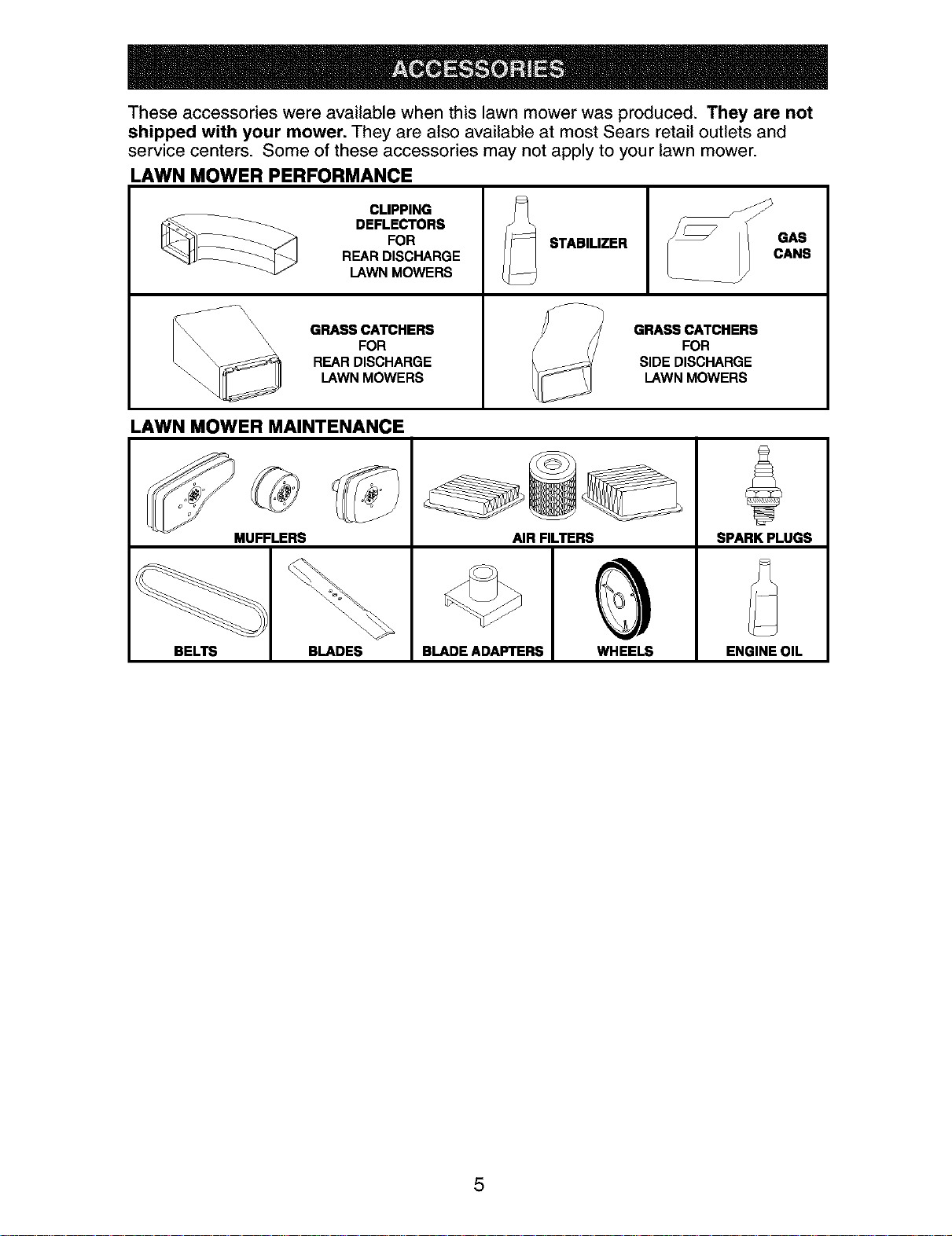
These accessories were available when this lawn mower was produced. They are not
shipped with your mower. They are also available at most Sears retail outlets and
service centers. Some of these accessories may not apply to your lawn mower.
LAWN MOWER PERFORMANCE
CLIPPING
DEFLECTORS
FOR
REAR DISCHARGE
LAWN MOWERS
\\ GRASS CATCHERS
_\_ \\\ FOR
REAR DISCHARGE
LAWN MOWERS
-- STABILIZER
GRASS CATCHERS
FOR
SIDE DISCHARGE
LAWN MOWERS
LAWN MOWER MAINTENANCE
MUFFLERS AIR FILTERS SPARK PLUGS
BELTS BLADES BLADE ADAPTERS WHEELS ENGINE OIL
5
Read these instructions and this manual in
its entirety before you attempt to assemble
or operate your new lawn mower.
IMPORTANT: This lawn mower is shipped
WITHOUT OIL OR GASOLINE in the engine.
Your new lawn mower has been as-
sembled at the factory with the excep-
tion of those parts left unassembled for
shipping purposes. To ensure safe and
proper operation of your lawn mower, all
parts and hardware you assemble must be
tightened securely. Use the correct tools
as necessary to ensure proper tightness.
All parts such as nuts, washers, bolts, etc.,
necessary to complete the assembly have
been placed in the parts bag.
TO REMOVE LAWN MOWER FROM
CARTON
1. Remove loose parts included with
mower.
2. Cut down two end corners of carton
and lay end panel down flat.
3. Remove all packing materials except
padding between upper and lower
handle and padding holding operator
presence control bar to upper handle.
4. Roll lawn mower out of carton and
check carton thoroughly for additional
loose parts.
HOWTO SET UPYOUR LAWN
MOWER
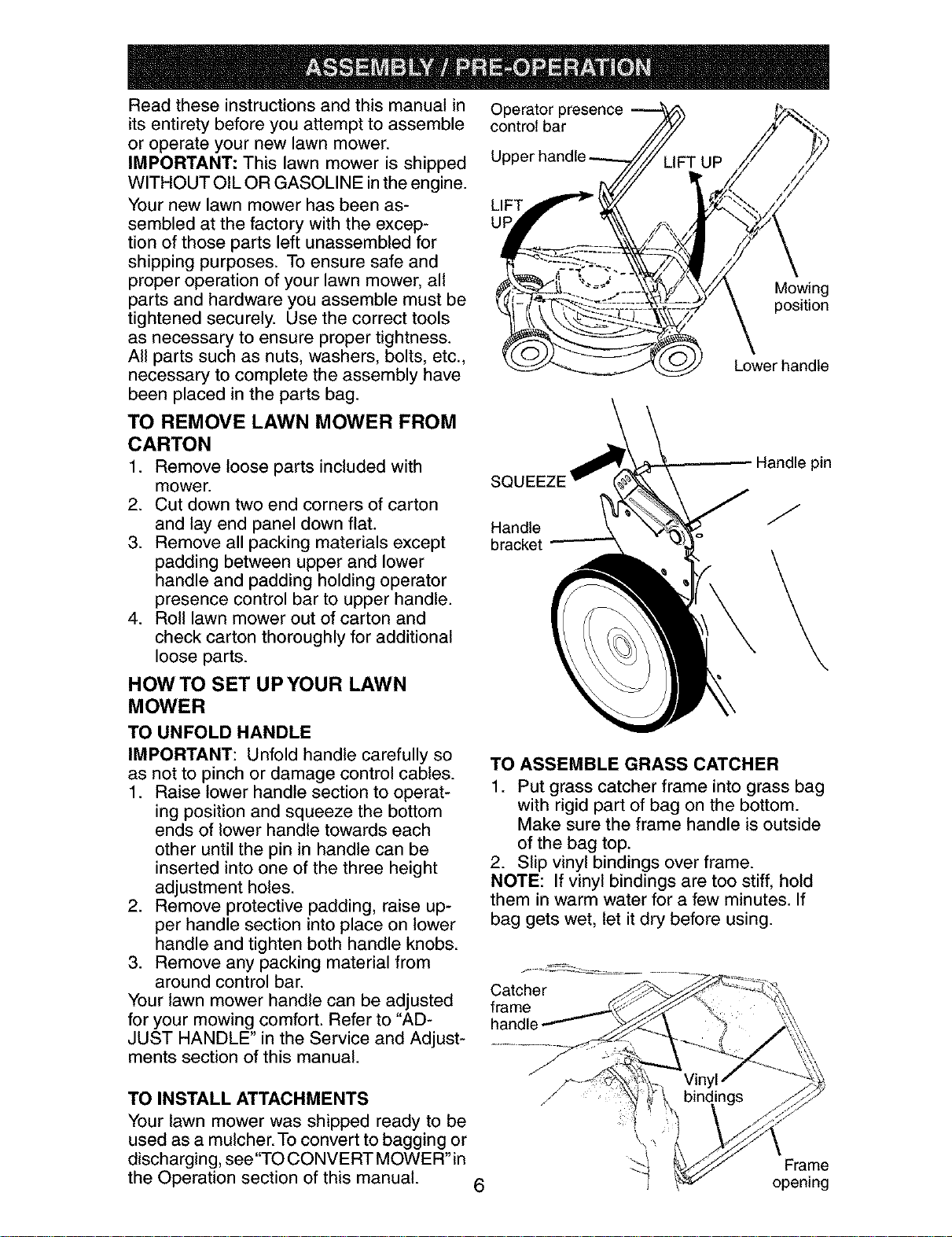
TO UNFOLD HANDLE
IMPORTANT: Unfold handle carefully so
as not to pinch or damage control cables.
1. Raise lower handle section to operat-
ing position and squeeze the bottom
ends of lower handle towards each
other until the pin in handle can be
inserted into one of the three height
adjustment holes.
2. Remove protective padding, raise up-
per handle section into place on lower
handle and tighten both handle knobs.
3. Remove any packing material from
around control bar.
Your lawn mower handle can be adjusted
for your mowing comfort. Refer to "AD-
JUST HANDLE" in the Service and Adjust-
ments section of this manual.
Operator presence
control bar
LIFT
UF
Mowing
position
Lower handle
SQL
Handle
bracket
Handle pin
J
TO ASSEMBLE GRASS CATCHER
1. Put grass catcher frame into grass bag
with rigid part of bag on the bottom.
Make sure the frame handle is outside
of the bag top.
2. Slip vinyl bindings over frame.
NOTE: If vinyl bindings are too stiff, hold
them in warm water for a few minutes. If
bag gets wet, let it dry before using.
Catcher
frame
handle
TO INSTALL ATTACHMENTS
Your lawn mower was shipped ready to be
used as a mulcher. To convert to bagging or
discharging, see"TO CONVERT MOWER"in
the Operation section of this manual.
6
/
/
Frame
opening
KNOW YOUR LAWN MOWER
READ THIS OWNER'S MANUAL AND ALL SAFETY RULES BEFORE OPERATING
YOUR LAWN MOWER. Compare the illustrations with your lawn mower to familiarize
yourself with the location of various controls and adjustments. Save this manual for
future reference.
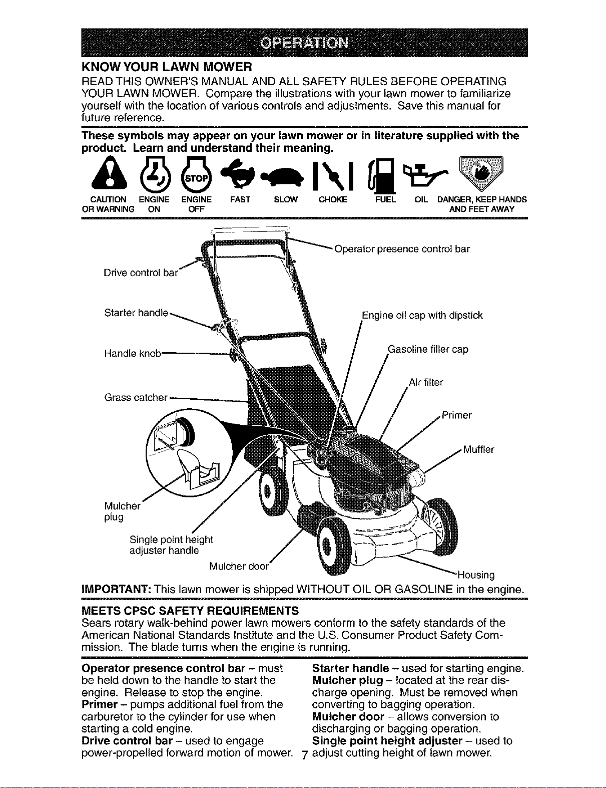
These symbols may appear on your lawn mower or in literature supplied with the
product. Learn and understand their meaning.
CAUTION ENGINE ENGINE FAST SLOW CHOKE FUEL OIL DANGER,KEEPHANDS
ORWARNING ON OFF AND FEET AWAY
Operator presence control bar
Drive control bar
Starter
Engine oil cap with dipstick
Handle knob
Gasoline filler cap
Grass catcher
Air filter
Mulcher
plug
Single point height
adjuster handle
Mulcher door"
'Housing
IMPORTANT: This lawn mower is shipped WITHOUT OIL OR GASOLINE in the engine.
MEETS CPSC SAFETY REQUIREMENTS
Sears rotary walk-behind power lawn mowers conform to the safety standards of the
American National Standards Institute and the U.S. Consumer Product Safety Com-
mission. The blade turns when the engine is running.
Operator presence control bar - must
be held down to the handle to start the
engine. Release to stop the engine.
Primer - pumps additional fuel from the
carburetor to the cylinder for use when
starting a cold engine.
Drive control bar - used to engage
power-propelled forward motion of mower. 7
Starter handle - used for starting engine.
Mulcher plug - located at the rear dis-
charge opening. Must be removed when
converting to bagging operation.
Mulcher door - allows conversion to
discharging or bagging operation.
Single point height adjuster - used to
adjust cutting height of lawn mower.
Theoperationof anylawn
mowercan resultin foreign
objectsthrownintothe
eyes,whichcan resultin
severeeyedamage.Always
wearsafetyglassesoreyeshieldswhile
operatingyour lawnmoweror performing
anyadjustmentsor repairs.We recom-
mendastandardsafetyglassesorwide
visionsafetymaskwornoverspectacles.
HOW TO USE YOUR LAWN MOWER
ENGINE SPEED
The engine speed was set at the factory
for optimum performance. Speed is not
adjustable.
ENGINE ZONE CONTROL
_CAUTION: Federal regulations require
an engine control to be installed on this
lawn mower in order to minimize the
risk of blade contact injury.Do not under
any circumstances attempt to defeat the
function of the operator control. The blade
turns when the engine is running.
• Your lawn mower is equipped with an
operator presence control bar which
requires the operator to be positioned
behind the lawn mower handle to start
and operate the lawn mower.
DRIVE CONTROL
• Self-propelling is controlled by hold-
ing the operator presence control bar
down to the handle and pulling the drive
control bar up to the handle. The closer
to the handle the bar is pulled, the faster
the unit will travel.
• Forward motion will stop when either the
operator presence control bar or drive
control bar are released. To stop forward
motion without stopping engine, release
the drive control bar only. Hold operator
presence control bar down against
handle to continue mowing without self-
propelling.
NOTE: If after releasing the drive control
the mower will not roll backwards, push
the mower forward slightly to disengage
drive wheels.
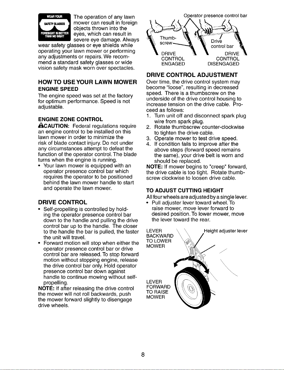
_rator presence control bar
}rive
control bar
DRIVE DRIVE
CONTROL CONTROL
ENGAGED DISENGAGED
DRIVE CONTROL ADJUSTMENT
Over time, the drive control system may
become "loose", resulting in decreased
speed. There is a thumbscrew on the
underside of the drive control housing to
increase tension on the drive cable. Pro-
ceed as follows:
f. Turn unit off and disconnect spark plug
wire from spark plug.
2. Rotate thumbscrew counter-clockwise
to tighten the drive cable.
3. Operate mower to test drive speed.
4. If condition fails to improve after the
above steps (forward speed remains
the same), your drive belt is worn and
should be replaced.
NOTE: If mower begins to "creep" forward,
the drive cable is too tight. Rotate thumb-
screw clockwise to loosen drive cable.
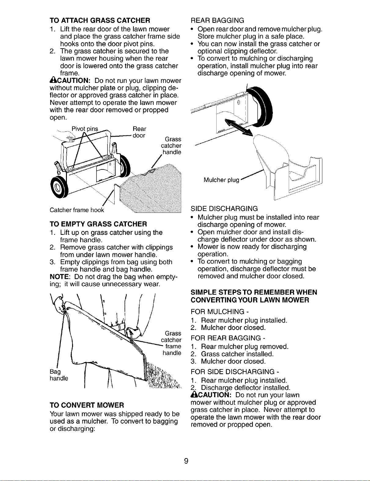
TO ADJUST CUTTING HEIGHT
All four wheels are adjusted by a single lever.
• Pull adjuster lever toward wheel. To
raise mower, move lever forward to
desired position. To lower mower, move
the lever toward the rear.
LEVER
BACKWARD
TO LOWER
MOWER
Height adjuster lever
LEVER
FORWARD
TO RAISE
MOWER
8
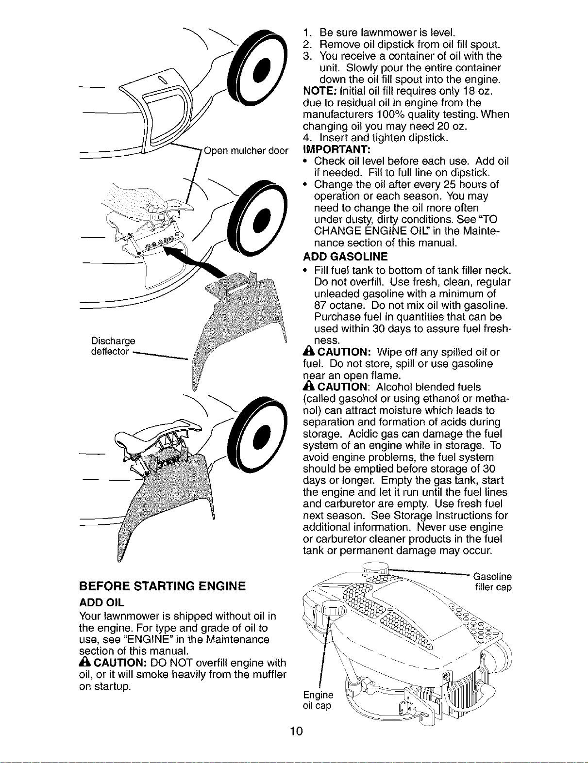
TO ATTACH GRASS CATCHER
1. Lift the rear door of the lawn mower
and place the grass catcher frame side
hooks onto the door pivot pins.
2. The grass catcher is secured to the
lawn mower housing when the rear
door is lowered onto the grass catcher
frame.
_CAUTION: Do not run your lawn mower
without mulcher plate or plug, clipping de-
flector or approved grass catcher in place.
Never attempt to operate the lawn mower
with the rear door removed or propped
open.
Pivot " Rear
Grass
catcher
handle
Catcher frame hook
TO EMPTY GRASS CATCHER
1. Lift up on grass catcher using the
frame handle.
2. Remove grass catcher with clippings
from under lawn mower handle.
3. Empty clippings from bag using both
frame handle and bag handle.
NOTE: Do not drag the bag when empty-
ing; it will cause unnecessary wear.
Grass
catcher
frame
handle
Bag
handle
TO CONVERT MOWER
Your lawn mower was shipped ready to be
used as a mulcher. To convert to bagging
or discharging:
REAR BAGGING
• Open rear door and remove mulcher plug.
Store mulcher plug in a safe place.
• You can now install the grass catcher or
optional clipping deflector.
• To convert to mulching or discharging
operation, install mulcher plug into rear
discharge opening of mower.
\\
\
Mulcher
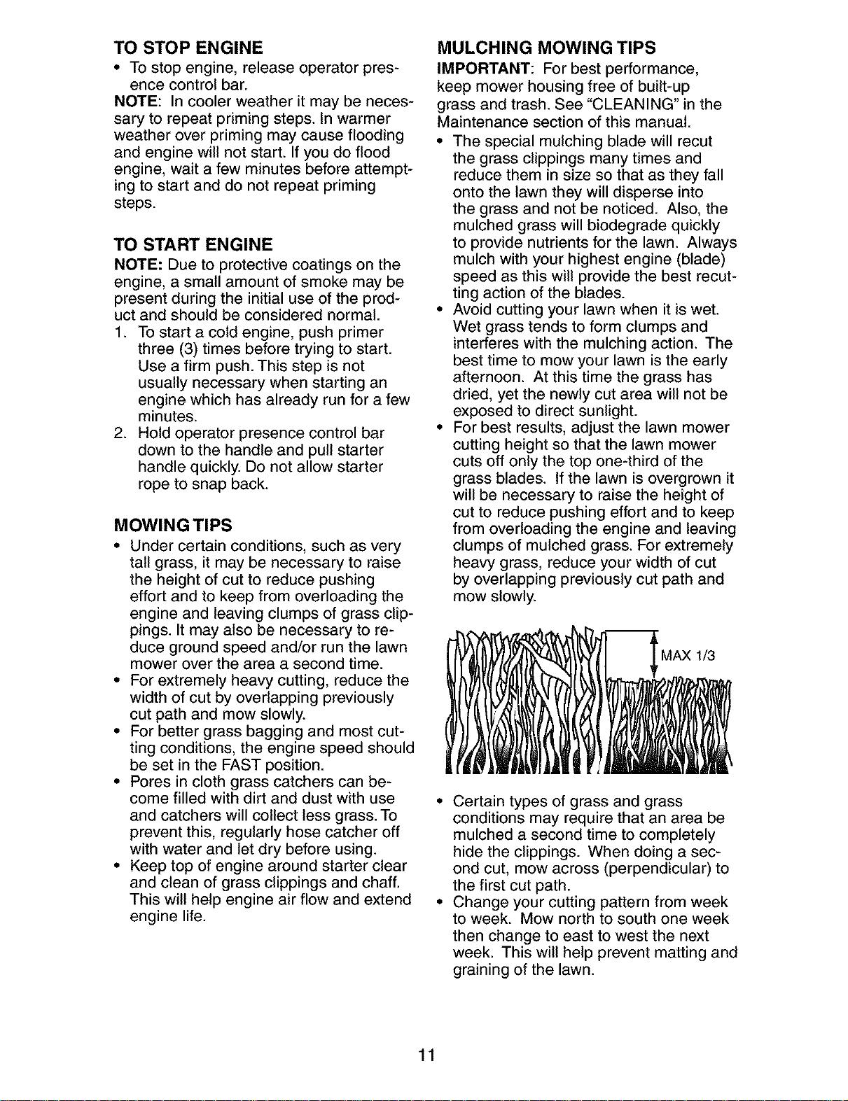
SIDE DISCHARGING
• Mulcher plug must be installed into rear
discharge opening of mower.
• Open mulcher door and install dis-
charge deflector under door as shown.
• Mower is now ready for discharging
operation.
• To convert to mulching or bagging
operation, discharge deflector must be
removed and mulcher door closed.
SIMPLE STEPS TO REMEMBER WHEN
CONVERTING YOUR LAWN MOWER
FOR MULCHING -
1. Rear mulcher plug installed.
2. Mulcher door closed.
FOR REAR BAGGING -
1. Rear mulcher plug removed.
2. Grass catcher installed.
3. Mulcher door closed.
FOR SIDE DISCHARGING -
1. Rear mulcher plug installed.
_:_ Discharge deflector installed.
CAUTION: Do not run your lawn
mower without mulcher plug or approved
grass catcher in place. Never attempt to
operate the lawn mower with the rear door
removed or propped open.
9
Discharge
deflector
,Open mulcher door
1. Be sure lawnmower is level.
2. Remove oil dipstick from oil fill spout.
3. You receive a container of oil with the
unit. Slowly pour the entire container
down the oil fill spout into the engine.
NOTE: Initial oil fill requires only 18 oz.
due to residual oil in engine from the
manufacturers 100% quality testing. When
changing oil you may need 20 oz.
4. Insert and tighten dipstick.
IMPORTANT:
• Check oil level before each use. Add oil
if needed. Fill to full line on dipstick.
• Change the oil after every 25 hours of
operation or each season. You may
need to change the oil more often
under dusty, dirty conditions. See "TO
CHANGE ENGINE OIE' in the Mainte-
nance section of this manual.
ADD GASOLINE
• Fill fuel tank to bottom of tank filler neck.
Do not overfill. Use fresh, clean, regular
unleaded gasoline with a minimum of
87 octane. Do not mix oil with gasoline.
Purchase fuel in quantities that can be
used within 30 days to assure fuel fresh-
Bess.
_, CAUTION: Wipe off any spilled oil or
fuel. Do not store, spill or use gasoline
near an open flame.
• 1=CAUTION: Alcohol blended fuels
(called gasohol or using ethanol or metha-
nol) can attract moisture which leads to
separation and formation of acids during
storage. Acidic gas can damage the fuel
system of an engine while in storage. To
avoid engine problems, the fuel system
should be emptied before storage of 30
days or longer. Empty the gas tank, start
the engine and let it run until the fuel lines
and carburetor are empty. Use fresh fuel
next season. See Storage Instructions for
additional information. Never use engine
or carburetor cleaner products in the fuel
tank or permanent damage may occur.
BEFORE STARTING ENGINE
ADD OIL
Your lawnmower is shipped without oil in
the engine. For type and grade of oil to
use, see "ENGINE" in the Maintenance
section of this manual.
CAUTION: DO NOT overfill engine with
oil, or it will smoke heavily from the muffler
on startup.
Engine
oil cap
Gasoline
filler cap
10
TO STOP ENGINE
• To stop engine, release operator pres-
ence control bar.
NOTE: In cooler weather it may be neces-
sary to repeat priming steps. In warmer
weather over priming may cause flooding
and engine will not start. If you do flood
engine, wait a few minutes before attempt-
ing to start and do not repeat priming
steps.
TO START ENGINE
NOTE: Due to protective coatings on the
engine, a small amount of smoke may be
present during the initial use of the prod-
uct and should be considered normal.
1. To start a cold engine, push primer
three (3) times before trying to start.
Use a firm push. This step is not
usually necessary when starting an
engine which has already run for a few
minutes.
2. Hold operator presence control bar
down to the handle and pull starter
handle quickly. Do not allow starter
rope to snap back.
MOWING TIPS
• Under certain conditions, such as very
tall grass, it may be necessary to raise
the height of cut to reduce pushing
effort and to keep from overloading the
engine and leaving clumps of grass clip-
pings. It may also be necessary to re-
duce ground speed and/or run the lawn
mower over the area a second time.
• For extremely heavy cutting, reduce the
width of cut by overlapping previously
cut path and mow slowly.
• For better grass bagging and most cut-
ting conditions, the engine speed should
be set in the FAST position.
• Pores in cloth grass catchers can be-
come filled with dirt and dust with use
and catchers will collect less grass. To
prevent this, regularly hose catcher off
with water and let dry before using.
• Keep top of engine around starter clear
and clean of grass clippings and chaff.
This will help engine air flow and extend
engine life.
MULCHING MOWING TIPS
IMPORTANT: For best performance,
keep mower housing free of built-up
grass and trash. See "CLEANING" in the
Maintenance section of this manual.
• The special mulching blade will recut
the grass clippings many times and
reduce them in size so that as they fall
onto the lawn they will disperse into
the grass and not be noticed. Also, the
mulched grass will biodegrade quickly
to provide nutrients for the lawn. Always
mulch with your highest engine (blade)
speed as this will provide the best recut-
ting action of the blades.
• Avoid cutting your lawn when it is wet.
Wet grass tends to form clumps and
interferes with the mulching action. The
best time to mow your lawn is the early
afternoon. At this time the grass has
dried, yet the newly cut area will not be
exposed to direct sunlight.
• For best results, adjust the lawn mower
cutting height so that the lawn mower
cuts off only the top one-third of the
grass blades. If the lawn is overgrown it
will be necessary to raise the height of
cut to reduce pushing effort and to keep
from overloading the engine and leaving
clumps of mulched grass. For extremely
heavy grass, reduce your width of cut
by overlapping previously cut path and
mow slowly.
• Certain types of grass and grass
conditions may require that an area be
mulched a second time to completely
hide the clippings. When doing a sec-
ond cut, mow across (perpendicular) to
the first cut path.
• Change your cutting pattern from week
to week. Mow north to south one week
then change to east to west the next
week. This will help prevent matting and
graining of the lawn.
11
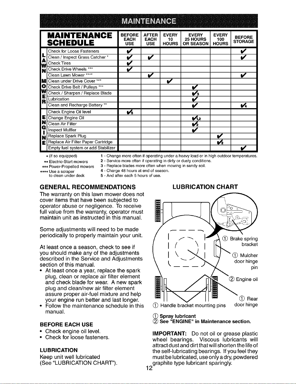
MAINTENANCE BEFOREAPTEREVERY EVERY EVERYBEFORE
EACH EACH 10 25HOURS 100
SCHEDULE USE USE HOURS ORSEASON HOURS STORAGE
Check for Loose Fasteners
L Clean / Inspect Grass Catcher *
Check Tires
_ Check Drive Wheels
Clean Lawn Mower ....
M Clean under Drive Cover ***
D Check Drive Belt / Pulleys ***
_ Check / Sharpen / Replace Blade
R Lubrication
Clean and Recharge Battery **
Check Engine Oil level
E Change Engine Oil
_ Clean Air Filter
Inspect Muffler
_1 Replace Spark Plug
E Replace Air Filter Paper Cartridge
Empty fuel system or add Stabilizer
i/ i/
i/
t/
t_,2
* (if so equipped)
** Electric-Start mowers
*** Power-Propelled mowers
**** Use a scraper
to clean under deck
1 - Change more often if operating under a heavy load or in high outdoor temperatures.
2 - Service more often if operating in dirty or dusty conditions.
3 - Replace blades more often when mowing in sandy soil.
4 - Charge 48 hours at end of season.
5 - And after each 5 hours of use.
GENERAL RECOMMENDATIONS
The warranty on this lawn mower does not
cover items that have been subjected to
operator abuse or negligence. To receive
full value from the warranty, operator must
maintain unit as instructed in this manual.
LUBRICATION CHART
Some adjustments will need to be made
periodically to properly maintain your unit.
At least once a season, check to see if
you should make any of the adjustments
described in the Service and Adjustments
section of this manual.
• At least once a year, replace the spark
plug, clean or replace air filter element
and check blade for wear. A new spark
plug and clean/new air filter element
assure proper air-fuel mixture and help
your engine run better and last longer.
• Follow the maintenance schedule in this
manual.
BEFORE EACH USE
• Check engine oil level.
• Check for loose fasteners.
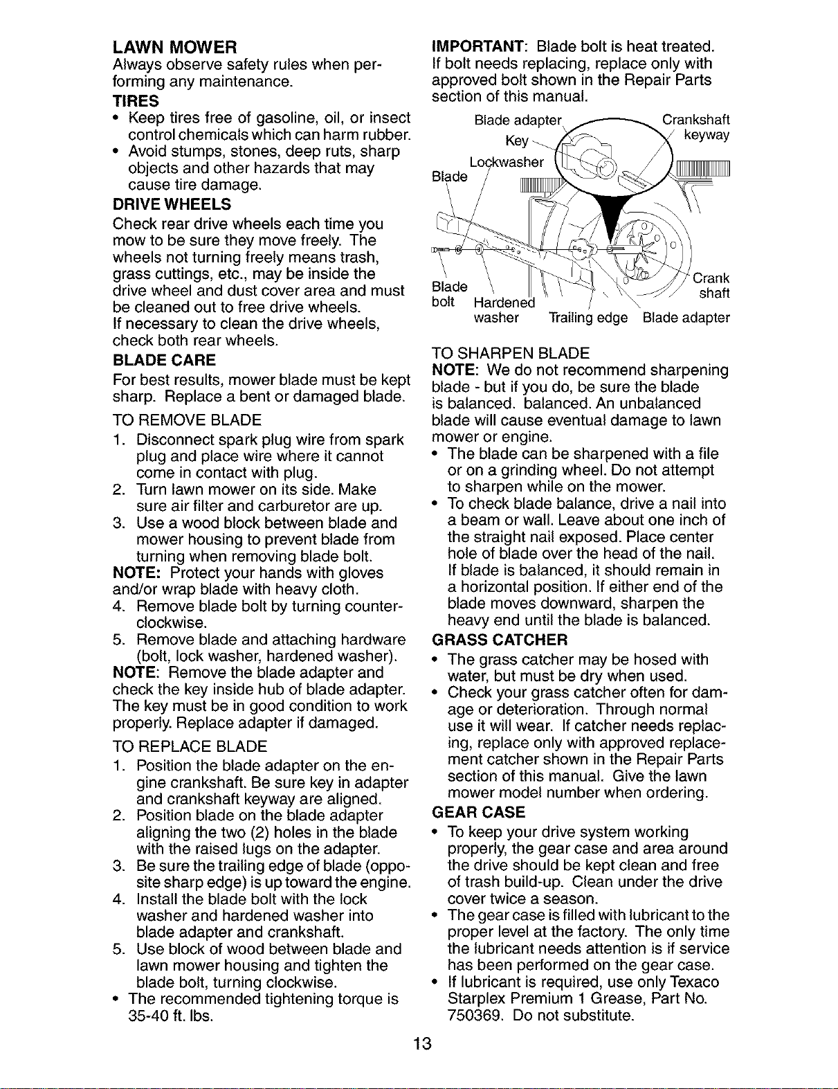
LUBRICATION
Keep unit well lubricated
(See "LUBRICATION CHART").
I
I
I
f _'_ _ Brake spring
(' "_ bracket
\ _" Mulcher
_ door hinge
pin
(_) Rear
Handle bracket mounting pins door hinge
_ Spray lubricant
See "ENGINE" in Maintenance section.
IMPORTANT: Do not oil or grease plastic
wheel bearings. Viscous lubricants will
attract dust and dirt that will shorten the life of
the self-lubricating bearings. If you feel they
must be lubricated, use only a dry, powdered
2graphite type lubricant sparingly.
1
LAWN MOWER
Always observe safety rules when per-
forming any maintenance.
TIRES
• Keep tires free of gasoline, oil, or insect
control chemicals which can harm rubber.
• Avoid stumps, stones, deep ruts, sharp
objects and other hazards that may
cause tire damage.
DRIVE WHEELS
Check rear drive wheels each time you
mow to be sure they move freely. The
wheels not turning freely means trash,
grass cuttings, etc., may be inside the
drive wheel and dust cover area and must
be cleaned out to free drive wheels.
If necessary to clean the drive wheels,
check both rear wheels.
BLADE CARE
For best results, mower blade must be kept
sharp. Replace a bent or damaged blade.
TO REMOVE BLADE
1. Disconnect spark plug wire from spark
plug and place wire where it cannot
come in contact with plug.
2. Turn lawn mower on its side. Make
sure air filter and carburetor are up.
3. Use a wood block between blade and
mower housing to prevent blade from
turning when removing blade bolt.
NOTE: Protect your hands with gloves
and/or wrap blade with heavy cloth.
4. Remove blade bolt by turning counter-
clockwise.
5. Remove blade and attaching hardware
(bolt, lock washer, hardened washer).
NOTE: Remove the blade adapter and
check the key inside hub of blade adapter.
The key must be in good condition to work
properly. Replace adapter if damaged.
TO REPLACE BLADE
1. Position the blade adapter on the en-
gine crankshaft. Be sure key in adapter
and crankshaft keyway are aligned.
2. Position blade on the blade adapter
aligning the two (2) holes in the blade
with the raised lugs on the adapter.
3. Be sure the trailing edge of blade (oppo-
site sharp edge) is up toward the engine.
4. Install the blade bolt with the lock
washer and hardened washer into
blade adapter and crankshaft.
5. Use block of wood between blade and
lawn mower housing and tighten the
blade bolt, turning clockwise.
• The recommended tightening torque is
35-40 ft. Ibs.
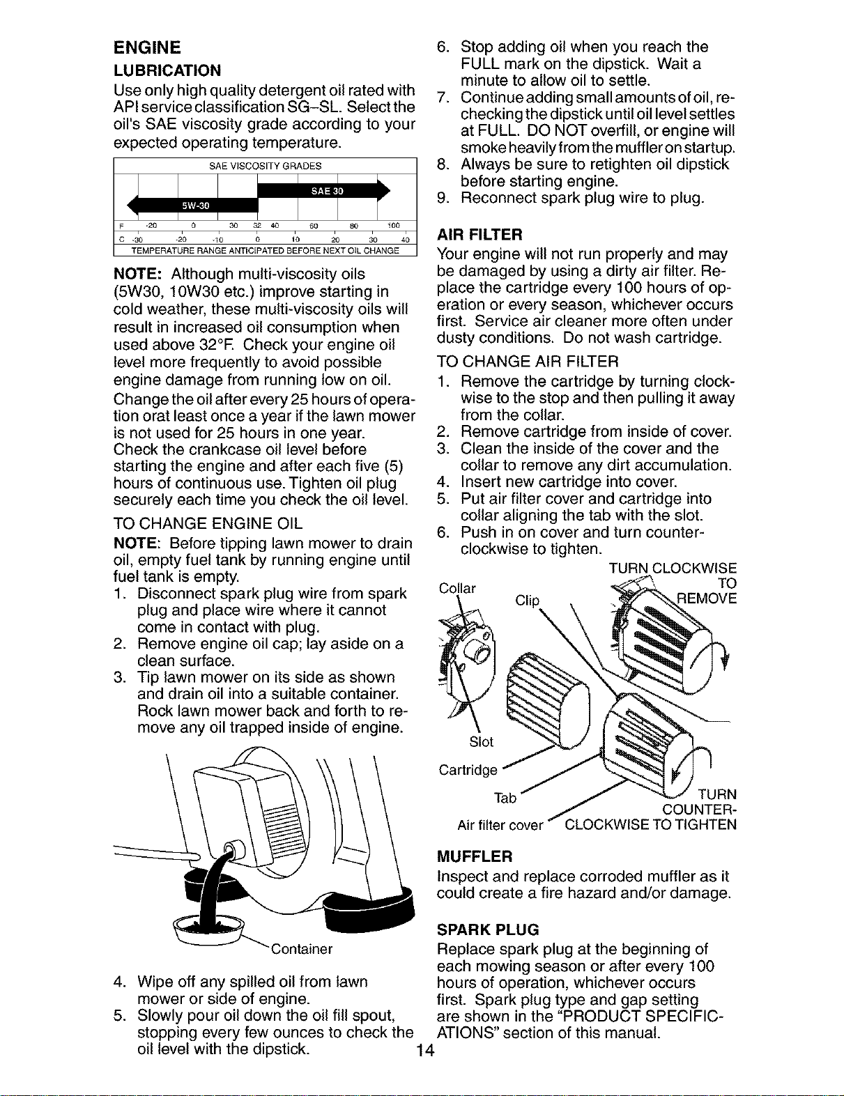
IMPORTANT: Blade bolt is heat treated.
If bolt needs replacing, replace only with
approved bolt shown in the Repair Parts
section of this manual.
Blade adapter Crankshaft
Key _ keyway
Blade
Crank
Blade shaft
bolt j \
washer Trailing edge Blade adapter
TO SHARPEN BLADE
NOTE: We do not recommend sharpening
blade - but if you do, be sure the blade
is balanced, balanced. An unbalanced
blade will cause eventual damage to lawn
mower or engine.
• The blade can be sharpened with a file
or on a grinding wheel. Do not attempt
to sharpen while on the mower.
• To check blade balance, drive a nail into
a beam or wall. Leave about one inch of
the straight nail exposed. Place center
hole of blade over the head of the nail.
If blade is balanced, it should remain in
a horizontal position. If either end of the
blade moves downward, sharpen the
heavy end until the blade is balanced.
GRASS CATCHER
• The grass catcher may be hosed with
water, but must be dry when used.
• Check your grass catcher often for dam-
age or deterioration. Through normal
use it will wear. If catcher needs replac-
ing, replace only with approved replace-
ment catcher shown in the Repair Parts
section of this manual. Give the lawn
mower model number when ordering.
GEAR CASE
• To keep your drive system working
properly, the gear case and area around
the drive should be kept clean and free
of trash build-up. Clean under the drive
cover twice a season.
• The gear case is filled with lubricant to the
proper level at the factory. The only time
the lubricant needs attention is if service
has been performed on the gear case.
• If lubricant is required, use only Texaco
Starplex Premium 1 Grease, Part No.
750369. Do not substitute.
13
ENGINE
LUBRICATION
Use only high quality detergent oil rated with
API service classification SG-SL. Select the
oil's SAE viscosity grade according to your
expected operating temperature.
SAE V_SCOSITY GRADES
-20 0 30 32 40 60 80 _00
.30 -20 .10 0 10 20 30 40
TEMPERATURE RANGE ANTICEPATED BEFORE NEXT OIL CHANGE
NOTE: Although multi-viscosity oils
(5W30, 10W30 etc.) improve starting in
cold weather, these multi-viscosity oils will
result in increased oil consumption when
used above 32°E Check your engine oil
level more frequently to avoid possible
engine damage from running low on oil.
Change the oil after every 25 hours of opera-
tion orat least once a year ifthe lawn mower
is not used for 25 hours in one year.
Check the crankcase oil level before
starting the engine and after each five (5)
hours of continuous use. Tighten oil plug
securely each time you check the oil level.
TO CHANGE ENGINE OIL
NOTE: Before tipping lawn mower to drain
oil, empty fuel tank by running engine until
fuel tank is empty.
1. Disconnect spark plug wire from spark tC°llar
plug and place wire where it cannot __
come in contact with plug.
2. Remove engine oil cap; lay aside on a
clean surface.
3. Tip lawn mower on its side as shown
and drain oil into a suitable container.
Rock lawn mower back and forth to re-
move any oil trapped inside of engine.
6. Stop adding oil when you reach the
FULL mark on the dipstick. Wait a
minute to allow oil to settle.
7. Continue adding small amounts of oil, re-
checking the dipstick until oil level settles
at FULL. DO NOT overfill, or engine will
smoke heavily from the muffler on startup.
8. Always be sure to retighten oil dipstick
before starting engine.
9. Reconnect spark plug wire to plug.
AIR FILTER
Your engine will not run properly and may
be damaged by using a dirty air filter. Re-
place the cartridge every 100 hours of op-
eration or every season, whichever occurs
first. Service air cleaner more often under
dusty conditions. Do not wash cartridge.
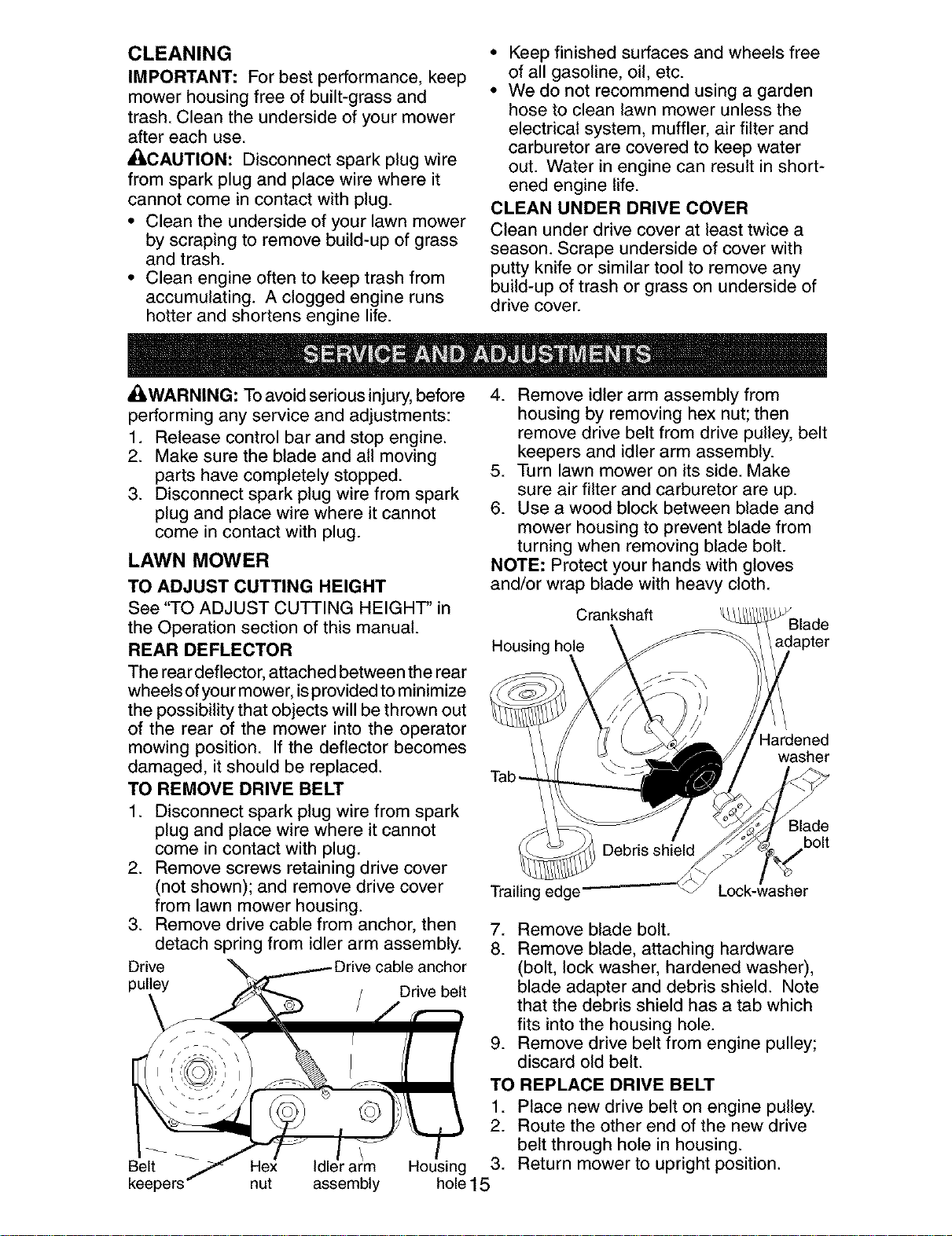
TO CHANGE AIR FILTER
1. Remove the cartridge by turning clock-
wise to the stop and then pulling it away
from the collar.
2. Remove cartridge from inside of cover.
3. Clean the inside of the cover and the
collar to remove any dirt accumulation.
4. Insert new cartridge into cover.
5. Put air filter cover and cartridge into
collar aligning the tab with the slot.
6. Push in on cover and turn counter-
clockwise to tighten.
Clip
TURN CLOCKWISE
TO
REMOVE
Slot
Cartridge
Tab TURN
COUNTER-
Air filter cover CLOCKWISE TO TIGHTEN
MUFFLER
Inspect and replace corroded muffler as it
could create a fire hazard and/or damage.
3ontainer
4. Wipe off any spilled oil from lawn
mower or side of engine.
5. Slowly pour oil down the oil fill spout,
stopping every few ounces to check the
oil level with the dipstick.
SPARK PLUG
Replace spark plug at the beginning of
each mowing season or after every 100
hours of operation, whichever occurs
first. Spark plug type and gap setting
are shown in the "PRODUCT SPECIFIC-
ATIONS" section of this manual.
14
CLEANING
IMPORTANT: For best performance, keep
mower housing free of built-grass and
trash. Clean the underside of your mower
after each use.
/ICAUTION: Disconnect spark plug wire
from spark plug and place wire where it
cannot come in contact with plug.
• Clean the underside of your lawn mower
by scraping to remove build-up of grass
and trash.
• Clean engine often to keep trash from
accumulating. A clogged engine runs
hotter and shortens engine life.
• Keep finished surfaces and wheels free
of all gasoline, oil, etc.
• We do not recommend using a garden
hose to clean lawn mower unless the
electrical system, muffler, air filter and
carburetor are covered to keep water
out. Water in engine can result in short-
ened engine life.
CLEAN UNDER DRIVE COVER
Clean under drive cover at least twice a
season. Scrape underside of cover with
putty knife or similar tool to remove any
build-up of trash or grass on underside of
drive cover.
ACIWARNING: To avoid serious injury, before
performing any service and adjustments:
1. Release control bar and stop engine.
2. Make sure the blade and all moving
parts have completely stopped.
3. Disconnect spark plug wire from spark
plug and place wire where it cannot
come in contact with plug.
LAWN MOWER
TO ADJUST CUTTING HEIGHT
See "TO ADJUST CUTTING HEIGHT' in
the Operation section of this manual.
REAR DEFLECTOR
The rear deflector, attached between the rear
wheels of your mower, isprovided to minimize
the possibility that objects will be thrown out
of the rear of the mower into the operator
mowing position. If the deflector becomes
damaged, it should be replaced.
TO REMOVE DRIVE BELT
1. Disconnect spark plug wire from spark
plug and place wire where it cannot
come in contact with plug.
2. Remove screws retaining drive cover
(not shown); and remove drive cover
from lawn mower housing.
3. Remove drive cable from anchor, then
detach spring from idler arm assembly.
Drive
pulley Drive belt
4. Remove idler arm assembly from
housing by removing hex nut; then
remove drive belt from drive pulley, belt
keepers and idler arm assembly.
5. Turn lawn mower on its side. Make
sure air filter and carburetor are up.
6. Use a wood block between blade and
mower housing to prevent blade from
turning when removing blade bolt.
NOTE: Protect your hands with gloves
and/or wrap blade with heavy cloth.
Crankshaft
Housing hole
Tab-
Hardened
washer
Blade
bolt
Trailing edge
7. Remove blade bolt.
8. Remove blade, attaching hardware
(bolt, lock washer, hardened washer),
blade adapter and debris shield. Note
that the debris shield has a tab which
fits into the housing hole.
9. Remove drive belt from engine pulley;
discard old belt.
Belt
nut assembly
TO REPLACE DRIVE BELT
1. Place new drive belt on engine pulley.
2. Route the other end of the new drive
belt through hole in housing.
Housing 3. Return mower to upright position.
hole15
4. Installnewdrivebeltinto idlerarm
assembly,then aroundthedrivepulley.
Besure beltis insideofbelt keepers.
5. Reattachidlerarmassemblywith hex
nutpreviouslyremoved.
6. Turnlawnmoweron itsside.Make
sureair filterandcarburetorare up.
7. Reattachdebrisshieldto housingwith
tabof debrisshield inhousinghole.
8. Positionbladeon thebladeadapter
aligningthetwo (2)holesin theblade
withthe raisedlugsonthe adapter.
9. Besurethetrailingedgeofblade(op-
positesharpedge)is uptowardthe
engineas shown.
10.Installthebladeboltwith thelock
washerandhardenedwasherinto
bladeadapterandcrankshaft.
11.Useblockofwoodbetweenbladeand
lawnmowerhousingandtightenthe
bladebolt,turningclockwise.
• The recommendedtighteningtorqueis
35-40ft. Ibs.
IMPORTANT:Bladeboltis heattreated.
Ifboltneedsreplacing,replaceonlywith
approvedbolt showninthe RepairParts
sectionof this manual.
12.Returnmowerto uprightposition.
13.Reattachdrivecablespringto theidler
armassembly,thenreattachdrive
cableto anchor.
14.Reattachdrivecoverwithscrewsprevi-
ouslyremoved.
15.Connectsparkplugwireto sparkplug.
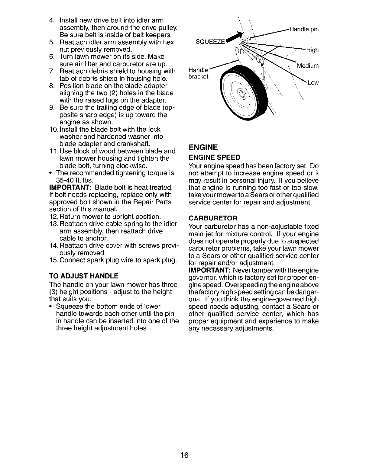
TO ADJUST HANDLE
The handle on your lawn mower has three
(3) height positions - adjust to the height
that suits you.
• Squeeze the bottom ends of lower
handle towards each other until the pin
in handle can be inserted into one of the
three height adjustment holes.
SQL
bracket
pin
High
Medium
\
\\
ENGINE
ENGINE SPEED
Your engine speed has been factory set. Do
not attempt to increase engine speed or it
may result in personal injury. If you believe
that engine is running too fast or too slow,
take you rmower to a Sears or other qualified
service center for repair and adjustment.
CARBURETOR
Your carburetor has a non-adjustable fixed
main jet for mixture control. If your engine
does not operate properly due to suspected
carburetor problems, take your lawn mower
to a Sears or other qualified service center
for repair and/or adjustment.
IMPORTANT: Never tamper with the engine
governor, which is factory set for proper en-
gine speed. Overspeeding the engine above
the factory high speed setting can be danger-
ous. If you think the engine-governed high
speed needs adjusting, contact a Sears or
other qualified service center, which has
proper equipment and experience to make
any necessary adjustments.
16
Immediately prepare your lawn mower for storage at the end of the season or if the unit
will not be used for 30 days or more.
LAWN MOWER
When lawn mower is to be stored for a
period of time, clean it thoroughly, remove
all dirt, grease, leaves, etc. Store in a
clean, dry area.
1. Clean entire lawn mower (See
"CLEANING" in the Maintenance sec-
tion of this manual).
2. Lubricate as shown in the Maintenance
section of this manual.
3. Be sure that all nuts, bolts, screws, and
pins are securely fastened. Inspect
moving parts for damage, breakage
and wear. Replace if necessary.
4. Touch up all rusted or chipped paint
surfaces; sand lightly before painting.
SQUEEZE
Handle
bracket
pin
J
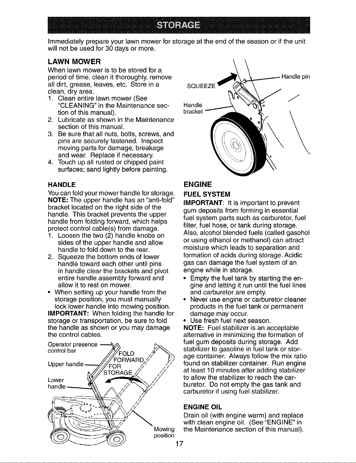
HANDLE
You can fold your mower handle for storage.
NOTE: The upper handle has an "anti-fold"
bracket located on the right side of the
handle. This bracket prevents the upper
handle from folding forward, which helps
protect control cable(s) from damage.
1. Loosen the two (2) handle knobs on
sides of the upper handle and allow
handle to fold down to the rear.
2. Squeeze the bottom ends of lower
handle toward each other until pins
in handle clear the brackets and pivot
entire handle assembly forward and
allow it to rest on mower.
• When setting up your handle from the
storage position, you must manually
lock lower handle into mowing position.
IMPORTANT: When folding the handle for
storage or transportation, be sure to fold
the handle as shown or you may damage
the control cables.
Operator presence
control bar
Lower
ENGINE
FUEL SYSTEM
IMPORTANT: It is important to prevent
gum deposits from forming in essential
fuel system parts such as carburetor, fuel
filter, fuel hose, or tank during storage.
Also, alcohol blended fuels (called gasohol
or using ethanol or methanol) can attract
moisture which leads to separation and
formation of acids during storage. Acidic
gas can damage the fuel system of an
engine while in storage.
• Empty the fuel tank by starting the en-
gine and letting it run until the fuel lines
and carburetor are empty.
• Never use engine or carburetor cleaner
products in the fuel tank or permanent
damage may occur.
• Use fresh fuel next season.
NOTE: Fuel stabilizer is an acceptable
alternative in minimizing the formation of
fuel gum deposits during storage. Add
stabilizer to gasoline in fuel tank or stor-
age container. Always follow the mix ratio
found on stabilizer container. Run engine
at least 10 minutes after adding stabilizer
to allow the stabilizer to reach the car-
buretor. Do not empty the gas tank and
carburetor if using fuel stabilizer.
ENGINE OIL
Mowing
position
Drain oil (with engine warm) and replace
with clean engine oil. (See "ENGINE" in
the Maintenance section of this manual).
17
CYLINDER
1. Remove spark plug.
2. Pour one ounce (29 ml) of oil through
spark plug hole into cylinder.
3. Pull starter handle slowly a few times to
distribute oil.
4. Replace with new spark plug.
OTHER
• Do not store gasoline from one season
to another.
• Replace your gasoline can if your can
starts to rust. Rust and/or dirt in your
gasoline will cause problems.
• If possible, store your unit indoors and
cover it to protect it from dust and dirt.
• Cover your unit with a suitable protec-
tive cover that does not retain moisture.
Do not use plastic. Plastic cannot
breathe, which allows condensation to
form and will cause your unit to rust.
IMPORTANT: Never cover mower while
engine and exhaust areas are still warm.
_[I,CAUTION: Never store the lawn mower
with gasoline in the tank inside a building
where fumes may reach an open flame
or spark. Allow the engine to cool before
storing in any enclosure.
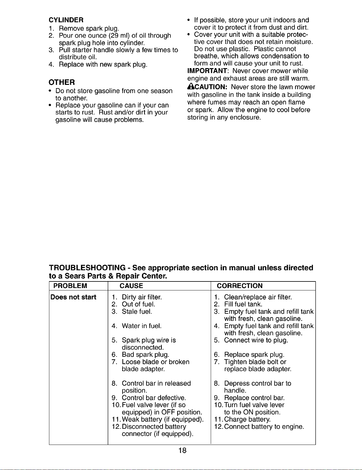
TROUBLESHOOTING - See appropriate section in manual unless directed
to a Sears Parts & Repair Center.
PROBLEM CAUSE CORRECTION
Does not start 1. Dirty air filter. 1. Clean/replace air filter.
2. Out of fuel.
3. Stale fuel.
4. Water in fuel.
5. Spark plug wire is
disconnected.
6. Bad spark plug.
7. Loose blade or broken
blade adapter.
8. Control bar in released
position.
2_
3.
4.
5.
6.
7.
Fill fuel tank.
Empty fuel tank and refill tank
with fresh, clean gasoline.
Empty fuel tank and refill tank
with fresh, clean gasoline.
Connect wire to plug.
Replace spark plug.
Tighten blade bolt or
replace blade adapter.
8. Depress control bar to
handle.
9. Control bar defective.
10. Fuel valve lever (if so
equipped) in OFF position.
11.Weak battery (if equipped).
12. Disconnected battery
connector (if equipped).
9. Replace control bar.
10.Turn fuel valve lever
to the ON position.
11.Charge battery.
12.Connect battery to engine.
18
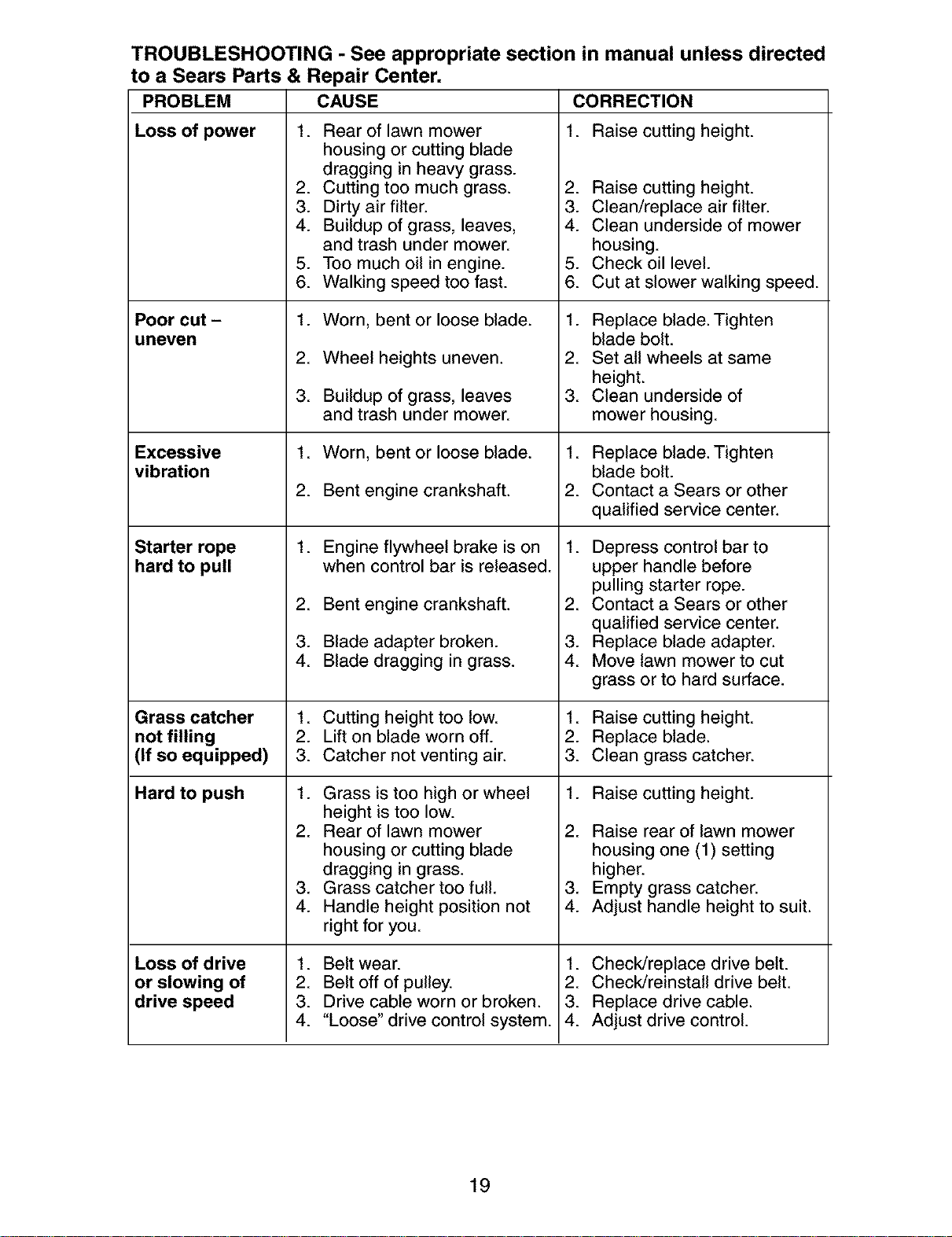
TROUBLESHOOTING - See appropriate section in manual unless directed
to a Sears Parts & Repair Center.
PROBLEM CAUSE
Loss of power 1. Rear of lawn mower
Poor cut -
uneven
Excessive
vibration
Starter rope
hard to pull
CORRECTION
1. Raise cutting height.
2. Raise cutting height.
3. Clean/replace air filter.
4. Clean underside of mower
housing.
5. Check oil level.
6. Cut at slower walking speed.
housing or cutting blade
dragging in heavy grass.
2. Cutting too much grass.
3. Dirty air filter.
4. Buildup of grass, leaves,
and trash under mower.
5. Too much oil in engine.
6. Walking speed too fast.
1. Worn, bent or loose blade.
2. Wheel heights uneven.
3. Buildup of grass, leaves
and trash under mower.
1. Worn, bent or loose blade.
2. Bent engine crankshaft.
1. Engine flywheel brake is on
when control bar is released.
2. Bent engine crankshaft.
3. Blade adapter broken.
4. Blade dragging in grass.
Cutting height too low.
Lift on blade worn off.
Catcher not venting air.
Grass is too high or wheel
height is too low.
2. Rear of lawn mower
housing or cutting blade
dragging in grass.
3. Grass catcher too full.
4. Handle height position not
right for you.
1. Belt wear.
2. Belt off of pulley.
3. Drive cable worn or broken.
4. "Loose" drive control system.
1. Replace blade. Tighten
blade bolt.
2. Set all wheels at same
height.
3. Clean underside of
mower housing.
1. Replace blade. Tighten
blade bolt.
2. Contact a Sears or other
qualified service center.
1. Depress control bar to
upper handle before
pulling starter rope.
2. Contact a Sears or other
qualified service center.
3. Replace blade adapter.
4. Move lawn mower to cut
grass or to hard surface.
Grass catcher 1. 1. Raise cutting height.
not filling 2. 2. Replace blade.
(If so equipped) 3. 3. Clean grass catcher.
Hard to push 1. 1. Raise cutting height.
Loss of drive
or slowing of
drive speed
2. Raise rear of lawn mower
housing one (1) setting
higher.
3. Empty grass catcher.
4. Adjust handle height to suit.
1. Check/replace drive belt.
2. Check/reinstall drive belt.
3. Replace drive cable.
4. Adjust drive control.
19
Garantia ......................................................... 20
Reglas de Seguridad ................................ 20-22
Especificaciones del Producto ....................... 22
Montaje / Pre-Operaci6n ............................... 24
Operaci6n ................................................. 25-29
Mantenimiento .......................................... 30-33
Programa de Mantenimiento ......................... 30
Servicio y Adjustes ................................... 33-34
Almacenamiento ....................................... 35-36
Identificaci6n de problemas ...................... 36-37
Partes de repuesto .................................. 38-45
Servicio Sears .................................. Contratapa
GARANTiA LIMITADA DE DOS AI_IOS PARA LA SEGADORA A MOTOR CRAFTSMAN
Per dos (2) aSos, a partir de la fecha de compra, cuando esta Segadora Craftsman se mantenga,
lubrique y afine segSn las instrucciones para la operaci6n y el mantenimiento en el manual del
dueSo, Sears repararA gratis todo defecto en el material y la mane de obra.
Si la Segadora Craftsman se usa para fines comerciates o de arriendo, esta garantia s61o se aplica
per noventa (90) dias a partir de la fecha de compra.
Esta Garantia no cubre:
• Arficulos que se desgastan durante el use normal tales come las cuchillas segadoras rotatorias,
los adaptadores de la cuchilla, las correas, los filtros de aire y las bujias.
• Reparaciones necesarias debido al abuse o a la negligencia del operador, incluy_ndose a los
cigeeSales doblados y a la falta de mantenimiento del equipo segSn las instrucciones que se
inctuyen en el manual del dueSo.
El servicio de garantfa esta disponible al devolver la segadora a motor Craftsman al Centro/Depart-
mento de Servicio Sears mas cercano en los Estados Unidos. Esta garantia se aplica solamente
mientras el producto este en use en los Estados Unidos.
Esta Garanfia le otorga derechos legales especfficos, y puede que tambi6n tenga otros derechos
que varfan de estado a estado.
Sears, Roebuck and Co., D/817WA, Hoffman Estates, IL 60179 USA
IMPORTANTE: Esta maquina cortadaora es capaz de amputar las manes y los manes y los pies y
de lanzar objetos. Si no se observan las instrucciones de seguridad siguientes se pueden producir
lesiones graves o la muerte.
_Busque este sfmbolo que sefala las precau-
ciones de seguridad de importancia. Quiere
decir - ii iATENCION!% i ESTE ALERTO!!!
SU SEGURIDAD ESTA COMPROMETIDA.
d_had)VERTENClA: Siempre desconecte el
alambre de la bujfa y p6ngato donde no pueda
entrar en contacto con la bujfa, para evitar et
arranque per accidente, durante la preparaci6n,
el transporte, el ajuste o cuando se hacen
reparaciones.
_DVERTENClA: Los bornes, terminales y
accesorios relatives de la bateria contienen
plomo o compuestos de plomo, productos
qufmicos conocidos en el Estado de California
come causa de cancer y defectos al nacimiento
u otros daSos reproductivos. Lavar lae manes
despu_e de manipularloe.
_[ILPRECAUCI(_N: El tube de escape del motor,
algunos de sus constituyentes y algunos com-
ponentes del vehfculo contienen o desprenden
productos qufmicos conocidos en el Estado de
California come causa de cancer y defectos at
nacimiento u otros daSos reproductivos.
_PRECAUCl0N: El silenciador y otras
piezas del motor llegan a sre extremadamente
calientes durante la operaci6n y siguen siendo
calientes despu_s de que el motor haya parade.
Para evitar quemaduras severas, permanezca
lejos de estas Areas.
20
I. OPERAClON
• Antes de empezar, debe familiarizarse comple-
tamente con los controles y el uso correcto de
la maquina. Para esto, debe leer y comprender
todas las instrucciones que aparecen en la ma-
quina yen los manuales de operaci6n.
• No ponga las manos o los pies cerca o
debajo de las partes rotatorias. Mant6ngase
siempre lejos de la abertura de la descarga.
• Permita que solamente las personas re-
sponsables que est6n familiarizadas con las
instrucciones operen la mAquina.
• Despeje el Area de objetos tales como pie-
dras, juguetes, alambres, huesos, palos, etc.
que pueden ser recogidos y lanzados por las
cuchillas.
• AsegSrese que el Area no se hallen per-
sonas, antes de segar. Pare la mAquina si
alguien entra en el Area.
• No opere la maquina sin zapatos o con sanda-
lias abiertas. P6ngase siempre zapatos s61idos.
• No tire de la segadora hacia atrAs a menos
que sea absolutamente necesado. Mire
siempre hacia abajo y hacia detrAs antes y
mientras que se mueve hacia atrAs.
• No opere la segadora sin los respectivos
resguardos, las placas, el recogedor de
c6sped u otros aditamentos dise ados para
su protecci6n y seguridad.
• Refi_rase alas instrucciones det fabricante
para el funcionamiento e instataci6n de
accesorios. Use t_nicamente accesorios
aprobados por el fabricante.
• Detenga la cuchilla o las cuchillas cuando cruce
por catzadas, calles o caminos de grava.
• Parar el motor cada vez que se abandona el
aparato, antes de limpiar la segadora o de
remover residuos del tubo.
• Apagar el motor y esperar hasta que las
cuchillas est_n completamente paradas
antes de remover el receptor de hierba.
• Segar solamente con luz del dfa o con una
buena luz artificial.
• No opere la mAquina bajo la influencia del
alcohol o de las drogas.
• Nunca opere la maquina cuando la hierba
est_ mojada. Asegt]rese siempre de tener
buena tracci6n en sus pies; mantenga el
mango firmemente y camine; nunca corra.
• Desconectar el mecanismo de propulsi6n
aut6noma o el embrague de transmisi6n en
las segadoras que Io tienen antes de poner
en marcha el motor.
• Si el equipo empezara a vibrar de una
manera anormal, pare el motor y revise de
inmediato para averiguar la causa. General-
mente la vibraci6n suele indicar que existe •
alguna averia.
• Siempre use gafas de seguridad o anteojos con •
protecci6n lateral cuando opere la segadora.
II. OPERACION SOBRE LAS CUESTAS
Los accidentes ocurren con mAs frecuencia en
las cuestas. Estos accidentes ocurren debido a
resbaladas o caidas, las cuales pueden resultar •
en graves lesiones. Operar la recortadora en
cuestas requiere mayor concentraci6n. Si se
siente inseguro en una cuesta, no la recorte.
21
HACER:
• Puede recortar a trav6s de la superficie de
la cuesta, nunca hacia ardba y hacia abajo.
Proceda con extrema precauci6n cuando
cambie de direcci6n en las cuestas.
• Renueva todos los objetos extraSos, tales
como guijarros, ramas, etc.
• Debe prestar atenci6n a hoyos, baches o
protuberancias. Recuerde que la hierba alta
puede esconder obstAculos.
NO HACER:
• No recorte cerca de pendientes, zanjas o
terraplenes. El operador puede perder la
tracci6n en los pies o el equilibrio.
• No recorte cuestas demasiado inclinadas.
• No recorte en hierba mojada. La reducci6n
en la tracci6n de la pisada puede causar
resbalones.
III. NINOS
Se pueden producir accidentes trAgicos si el
operador no presta atenci6n a la presencia
de los niSos. A menudo, los niSos se sienten
atraidos por la maquina y por la actividad de
la siega. Nunca suponga que los niSos van a
permanecer en el mismo lugar donde los vio
por _ltima vez.
• Mantenga a los niSos alejados del Area de
la siega y bajo el cuidado estricto de otra
persona adulta responsable.
• Est6 alerta y apague la maquina si hay niSos
que entran at Area.
• Antes y cuando este retrocediendo, mire
hacia atrAs y hacia abajo para verificar si hay
niSos pequeSos.
• Nunca permita que los ni_os operen la mAquina.
• Tenga un cuidado extra cuando se acerque
a esquinas donde no hay visibilidad, a los
arbustos, Arboles u otros objetos que pueden
interferir con su linea de visi6n.
IV. SERMIClO
• Tenga cuidado extra al manejar la gasolina y
los demAs combustibles. Son inflamables y
los gases son explosivos.
- Use solamente un envase aprobado.
- Nunca remueva la tapa del dep6sito de
gasolina o agregue combustible con el mo-
tor funcionando. Permita que el motor se
enfrfe antes de volver a pone combustible.
No fume.
- Nunca vuelva a poner combustible en la
mAquina en recintos cerrados.
- Nunca almacene la mAquina o el envase
del combustible dentro de algt]n lugar en
donde haya una llama expuesta, tat como
la del calentador de agua.
Nunca haga funcionar una mAquina dentro
de un Area cerrada.
Nunca haga ajustes o reparaciones mientras
el motor est_ en marcha. Desconecte et
cable de la bujfa, y mant_ngalo a cierta
distancia de 6sta para prevenir un arranque
accidental.
Mantenga las tuercas y los pernos, espe-
cialmente los pernos del accesorio de la
cuchilla, apretados y mantenga el equipo en
buenas condiciones.
• Nuncamanipuledeformaindebidalos
dispositivosdeseguridad.Controleregular-
mentesufuncionamientocorrecto.
• Mantengalam&quinalibredehierba,hojas
uotrasacumulacionesdedesperdicio.
Limpielosderramesdeaceiteocombustible.
Permitaquelam&quinaseenfrfeantesde
almacenarla.
• Pareeinspeccioneelequiposilepegaaun
objeto.Rep&relo,siesnecesario,antesde
hacerloarrancar.
• Enningt]ncasohayqueregularlaalturade
lasruedasmientrasel motorestAenmarcha.
• Loscomponentesdelreceptordelahierba
vansujetosadesgaste,daSosydetedoro,
quepuedenexponerlaspartesenmov-
imientoopermitirqueobjetosseandispara-
dos.Controlarfrecuentementeycuandosea
necesadosustituirconpartesaconsejadas
perelfabricante.
• Lascuchillasdelasegadoraest#,nafiladasy
puedencortar.Cubrirlashojasollevarguantes,
y utilizarprecaucionesespecialescuandose
efectt_amantenimientosobrelasmismas.
• Nocambieelajustedelreguladordelmotor
niexcedasuvelocidad.
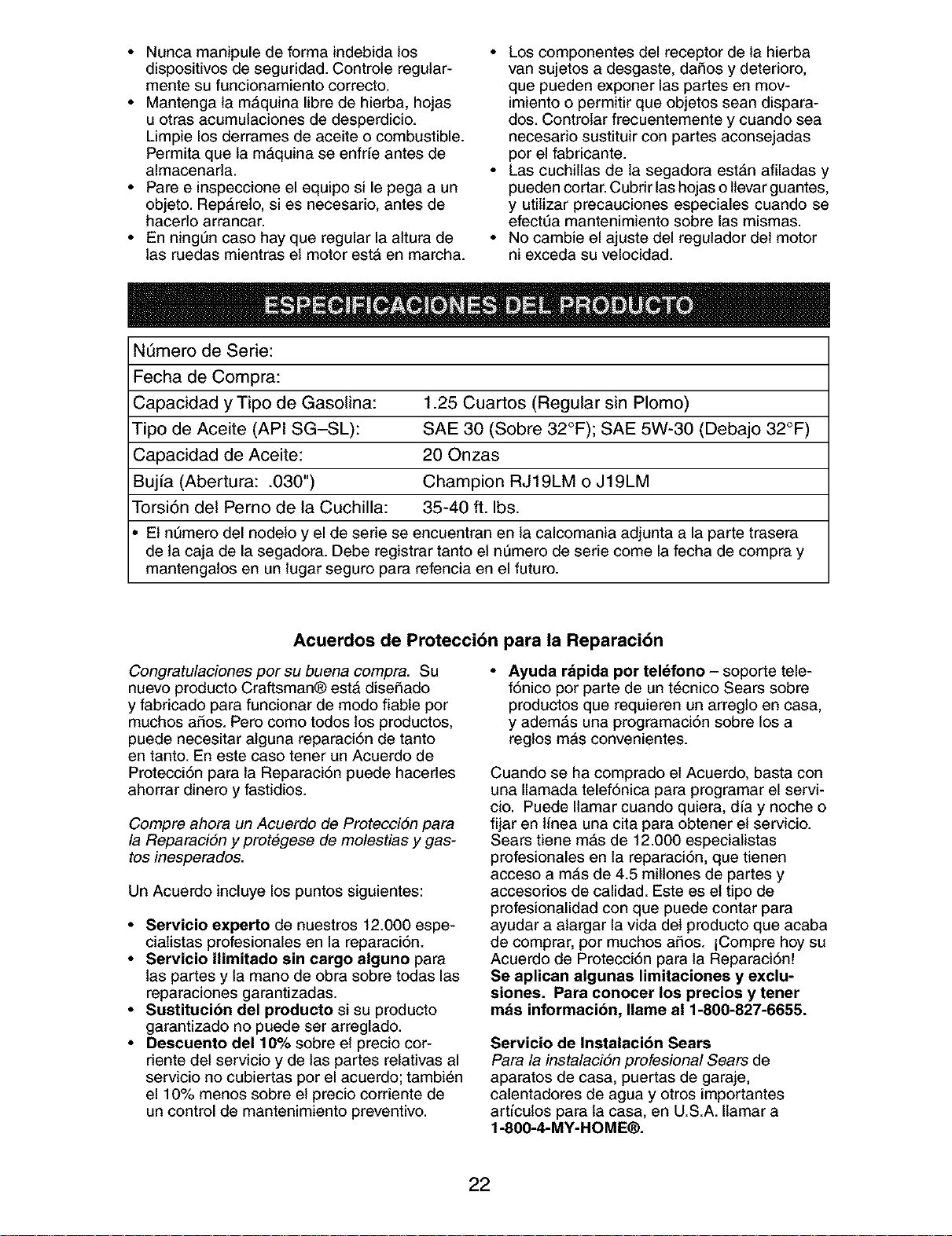
Nt_mero de Serie:
Fecha de Compra:
Capacidad y Tipo de Gasolina: 1.25 Cuartos (Regular sin Plomo)
Tipo de Aceite (API SG-SL): SAE 30 (Sobre 32°F); SAE 5W-30 (Debajo 32°F)
Capacidad de Aceite: 20 Onzas
Bujfa (Abertura: .030") Champion RJ19LM o J19LM
Torsi6n del Perno de la Cuchilla: 35-40 ft. Ibs.
El nt]mero del nodelo y el de serie se encuentran en la calcomania adjunta a la parte trasera
de ta caja de la segadora. Debe registrar tanto el nQmero de serie come la fecha de compra y
mantengatos en un lugar seguro para refencia en el futuro.
Acuerdos de Protecci6n para la Reparaci6n
Congratulaciones por su buena compra. Su
nuevo producto Craftsman® estA diseSado
y fabricado para funcionar de modo fiable por
muchos aSos. Pero como todos los productos,
puede necesitar alguna reparaci6n de tanto
en tanto. En este caso tener un Acuerdo de
Protecci6n para la Reparaci6n puede hacerles
ahorrar dinero y fastidios.
Compre ahora un Acuerdo de ProtecciSn para
la ReparaciSn y prot&gese de molestias y gas-
tos inesperados.
Un Acuerdo incluye los punto$ $iguientes:
• Servicio experto de nuestros 12.000 espe-
cialistas profesionales en la reparaci6n.
• Servicio ilimitado sin cargo alguno para
las partes y ta mano de obra sobre todas las
reparaciones garantizadas.
• Sustitucion del producto si su producto
garantizado no puede ser arreglado.
• Descuento de110% sobre el precio cor-
riente del servicio y de las partes relativas al
servicio no cubiertas por el acuerdo; tambi_n
el 10% menos sobre el precio corriente de
un control de mantenimiento preventive.
• Ayuda rapida por telefono - soporte tele-
f6nico per parte de un t6cnico Sears sobre
productos que requieren un arreglo en casa,
y adem#,s una programaci6n sobre los a
reglos mAs convenientes.
Cuando se ha comprado el Acuerdo, basta con
una Ilamada telef6nica para programar el servi-
cio. Puede Ilamar cuando quiera, alia y noche o
fijar en linea una cita para obtener el servicio.
Sears tiene m#,s de 12.000 especialistas
profesionales en la reparaci6n, que tienen
acceso a mAs de 4.5 millones de partes y
accesorios de calidad. Este es el tipo de
profesionalidad con que puede contar para
ayudar a alargar la vida det producto que acaba
de comprar, por muchos aSos. iCompre hoy su
Acuerdo de Protecci6n para la Reparaci6n!
Se aplican algunas limitaciones y exclu-
siones. Para conocer los precios y tener
mas informacion, Ilame al 1-800-827-6655.
Servicio de Instalacibn Sears
Para la instalaci6n profesional Sears de
aparatos de casa, puertas de garaje,
calentadores de agua y otros importantes
artfculos para ta casa, en U.S.A. Ilamar a
1-8OO-4-MY-HOME®.
22
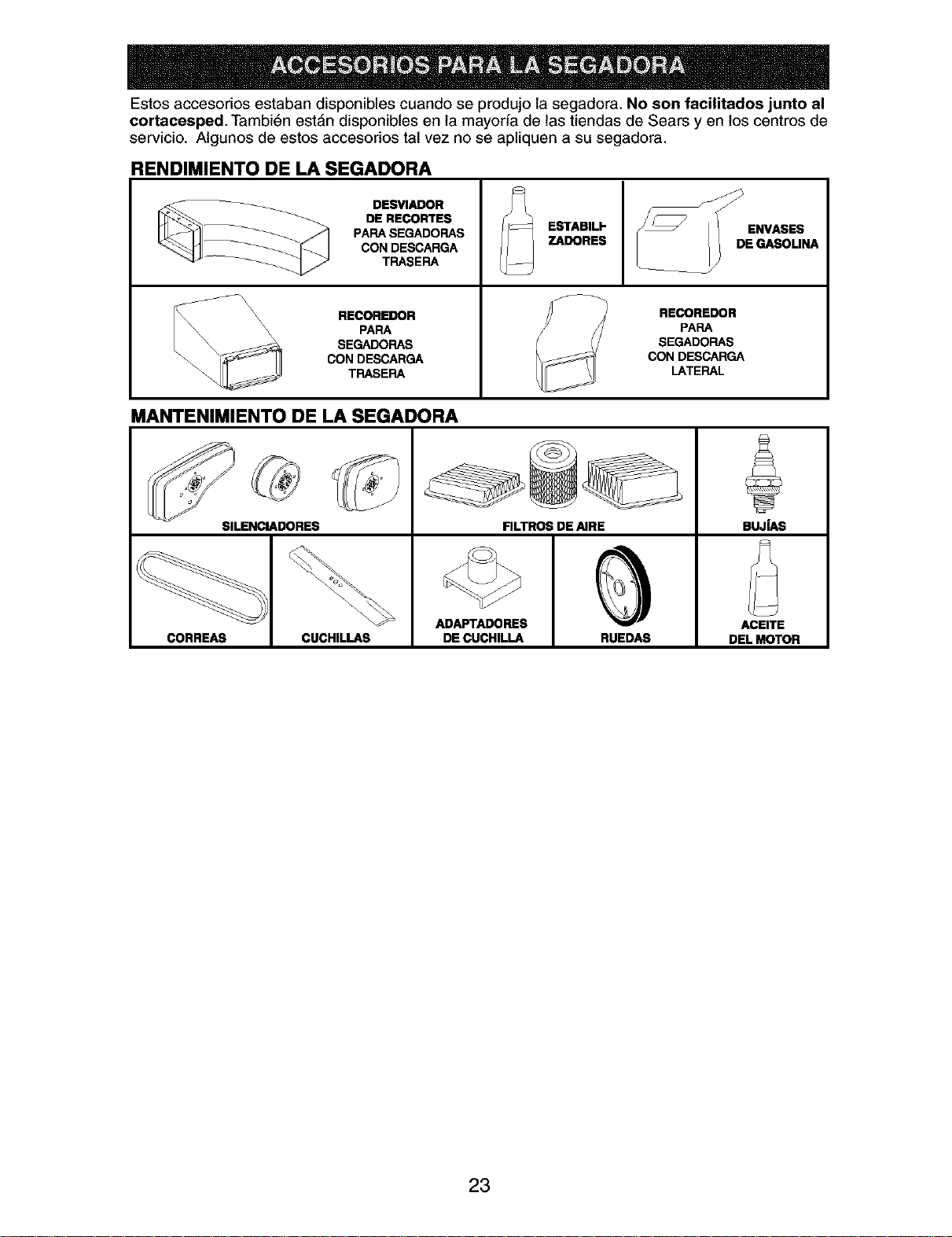
Estos accesorios estaban disponibles cuando se produjo la segadora. No son facilitados junto al
¢ortacesped. Tambi6n estAn disponibles en la mayoria de las tiendas de Sears y en los centros de
servicio. Algunos de estos accesorios tal vez no se apliquen a su segadora.
RENDIMIENTO DE LA SEGADORA
DESVIADOR
DE RECORTES
PAPA SEGADOFIAS
CON DESCARGA
TRASERA
RECOREDOR
\\\\ PARA
\\\ \
SEGADORAS
CON DESCARGA
TFIASEFIA
ESTABIU"
ZADORES
RECOREDOR
PAPA
SEGADORAS
CON DESCARGA
LATERAL
MANTENIMIENTO DE LA SEGADORA
SILENCIADORES FILTROS DE AIRE BUJfAS
ADAPTADORES ACEITE
CORREAS CUCHILLAS DE CUCHILLA RUEDAS DEL MOTOR
23
Lea estas instrucciones y este manual comple-
tamente antes de tratar de montar u operar su
segadora nueva.
IMPORTANTE: Este cortac_sped viene SIN
ACEITE O GASOLINA en el motor.
Su segadora nueva ha side montada en la
f&brica con la excepci6n de aquellas partes que
se dejaron sin montar por razones de envio.
Todas tas partes como las tuercas, tas arande-
las, los pernos, etc., que son necesadas para
completar el montaje han side colocadas en la
bolsa de partes. Para asegurarse que su sega-
dora funcione en forma segura y adecuada,
todas las partes y los arficulos de ferreteria que
se monten tienen que ser apretados segura-
mente. Use las herramientas correctas, como
sea necesario, para asegurar que se aprieten
adecuadamente.
PARA REMOVER LA SEGADORA DE
LA CAJA DE CARTON
1. Remueva las partes sueltas que se incluyen
con la segadora.
2. Corte las dos esquinas de los extremos
de la caja de cart6n y tienda el panel del
extremo piano.
3. Remueva todo el material de empaque, ex-
cepto la curia entre el mango superior y _1 Soportede
inferior, y la curia que sujeta la barra de los mango
control que exige la presencia del operador
junto con el mango superior.
4. Haga rodar la segadora hacia afuera de la
caja de cart6n y revisela cuidadosamente
para verificar si todavia quedan partes
sueltas adicionales.
COMO PREPARAR SU SEGADORA
PARA DESDOBLAR EL MANGO
IMPORTANTE: Despliegue el mango con
mucho cuidado para no pellizcar o dafiar los
cables de control.
1. Levante la secci6n del mango inferior a la
posici6n de operaci6n y presione las ex-
tremidades inferiores del mando inferior una
en contra una de la otra hasta que la pinza
det mando pueda ser insertada en uno de
los tres agujeros del control de ta altura.
2. Levante la secci6n del mango superior
hasta la posici6n de operaci6n, remueva la
curia protectora y apdete las manillas del
mango en forma segura.
3. Remueva et material de empaque de alred-
edor de la barra de control.
El mango de la segadora puede ajustarse Mangodel
segt_n le acomode para segar. Refi_rase a bastidordel
"AJUSTE DEL MANGO" en la secci6n de Servi- recogedor
cioy Ajustes de este manual.
PARA INSTALAR LOS ACCESORIOS
Su segadora rue enviada lista para usarse
como una acolchadora de capa vegetal. Para
convertirla de mode que pueda ensacar o
descargar, refi6rase a "PARA CONVERIR LA
SEGADORA" en la secci6n de Operaci6n de
este manual.
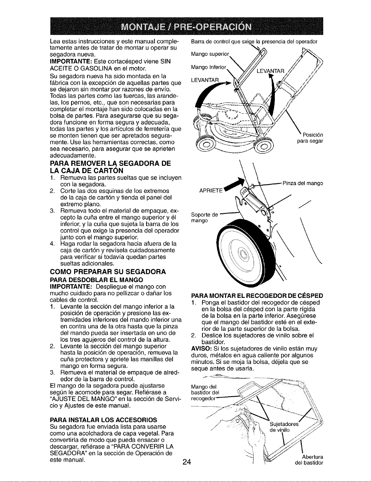
Barra de control que
Mango superior
Mango Inferior
LEVANTAR
la presencia del operador
Posici6n
para segar
a del mango
J
PARA MONTAR EL RECOGEDOR DE ClaSPED
1. Ponga el bastidor del recogedor de c6sped
en la bolsa del c_sped con la parte rfgida
de la bolsa en la parte inferior. Asegt]rese
que el mango del bastidor est_ en el exte-
rior de la parte superior de la bolsa.
2. Destice los sujetadores de vinilo sobre el
bastidor.
AVlSO: Si los sujetadores de vinilo est&n muy
duros, m6talos en agua catiente por algunos
minutos. Si se moja la bolsa, d6jela que se
seque antes de usarla.
24
Abertura
del bastidor
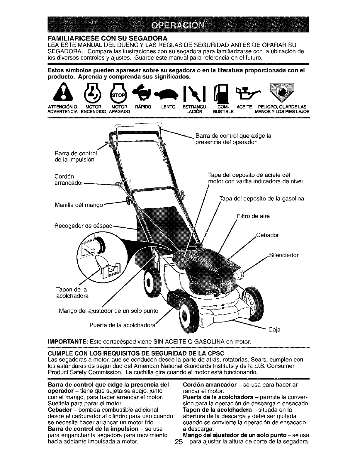
FAMILIARICESE CON SU SEGADORA
LEA ESTE MANUAL DEL DUENO Y LAS REGLAS DE SEGURIDAD ANTES DE OPARAR SU
SEGADORA. Compare las ilustraciones con su segadora para familiarizarse con la ubicaci6n de
los diversos controles y ajustes. Guarde este manual para referencia en el futuro.
Estos simbolos pueden apareser sobre su segadora o en la literatura proporcionada con el
producto. Aprenda y comprenda sus significados.
A'n'ENCI(_N O MOTOR MOTOR RAPIDO LENTO ESTRANGU COM- ACEITE PELIGRO, GUARDE LAS
ADVERTENCIA ENCENDIDO APAGADO LACI(SN BUSTIBLE MANOS Y LOS PIES LEJOS
Barra de control
de la impulsi6n
Barra de control que exige la
presencia del operador
Cord6n
Tapa del deposito de aciete del
motor con varilla indicadora de nivel
Manilla del mango
deposito de la gasolina
Filtro de aire
Silenciador
Tapon de la
acolchadora
Mango del ajustador de un solo punto
Puerta de la acolchadora
Caja
IMPORTANTE: Este cortac_sped viene SIN ACEITE O GASOLINA en motor.
CUMPLE CON LOS REQUISlTOS DE SEGURIDAD DE LA CPSC
Las segadoras a motor, que se conducen desde la parte de atr&s, rotatorias, Sears, cumplen con
los est&ndares de seguridad del American National Standards Institute y de la U.S. Consumer
Product Safety Commission. La cuchilla gira cuando el motor estA funcionando.
Barra de control que exige la presencia del
operador - tiene que sujetarse abajo, junto
con el mango, para hacer arrancar el motor.
Su_ltela para parar el motor.
Cebador - bombea combustible adicional
desde el carburador al cilindro para uso cuando
se necesita hacer arrancar un motor frio.
Barfs de control de la impulsion - se usa
para enganchar la segadora para movimiento
hacia adelante impulsada a motor.
Cordon arrancador - se usa para hacer ar-
rancar el motor.
Puerta de la acolchadora - permite la conver-
si6n para la operaci6n de descarga o ensacado.
Tapon de la acolchadera - situada en la
abertura de la descarga y debe ser quitada
cuando se convierte la operaci6n de ensacado
a descarga.
Mango del ajustador de un solo punto - se usa
25 para ajustar la altura de corte de la segadora.
Laoperaci6ndecualquier
segadorapuedehacerque
sattenobjetosextraSosdentrode
susojos,Ioquepuedeproducir
daSosgravesen_stos.Siempre
useanteojosdeseguridadoprotecci6npara
losojosmientrasoperesusegadoraocuando
hagaajustesoreparaciones.Recomendamos
gafasounamascaradeseguridaddevisi6n
ampliadeseguridadusadasobrelasgafas.
COMOUSAR SU SEGADORA
VELOCIDAD DEL MOTOR
La velocidad del motor se estableci6 en la fA-
brica para un rendimiento 6ptimo. La velocidad
no se puede ajustar.
_NTROL DE ZONA DEL MOTOR
PRECAUCI(_N: Las regulaciones federales
exigen que se instale un control para el motor
en esta segadora para reducir a un mfnimo el
riesgo de lesionarse debido al contacto con la
cuchilla. Por ningt]n motivo trate de eliminar
la funci6n del control del operador. La cuchilla
gira cuando el motor estA funcionando.
• Su segadora viene equipada con una barra
de controles que exigen la presencia del
operador, Io que requiere que el operador
est6 detrAs del mango de la segadora para
hacerla arrancar y operarla.
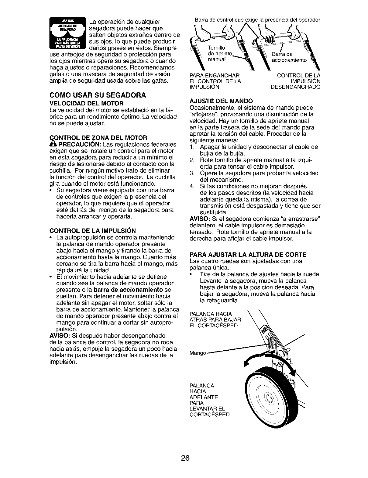
CONTROL DE LA IMPULSION
• La autopropulsi6n se controla manteniendo
la patanca de mando operador presente
abajo hacia el mango y tirando la barra de
accionamiento hasta la mango. Cuanto mAs
cercano se tira la barra hacia el mango, mAs
rApida ira la unidad.
• El movimiento hacia adelante se detiene
cuando sea la palanca de mando operador
presente o la barra de accionamiento se
sueltan. Para detener el movimiento hacia
adelante sin apagar el motor, soltar s61o la
barra de accionamiento. Mantener la palanca
de mando operador presente abajo contra el
mango para continuar a cortar sin autopro-
pulsi6n.
AMISO: Si despu_s haber desenganchado
de la palanca de control, la segadora no roda
hacia atrAs, empuje la segadora un poco hacia
adelante para desenganchar las ruedas de la
impulsi6n.
Barra de control que ,perador
Barra de
accionamiento
PARA ENGANCHAR
EL CONTROL DE LA
IMPULSION
CONTROL DE LA
IMPULSION
DESENGANCHADO
AJUSTE DEL MANDO
Ocasionalmente, el sistema de mando puede
"aflojarse', provocando una disminuci6n de la
velocidad. Hay un tornillo de apriete manual
en la parte trasera de la sede del mando para
apretar la tensi6n del cable. Proceder de la
siguiente manera:
1. Apagar la unidad y desconectar el cable de
bujfa de la bujfa.
2. Rote tornillo de apriete manual a la izqui-
erda para tensar et cable impulsor.
3. Opere la segadora para probar la velocidad
del mecanismo.
4. Si las condiciones no mejoran despu_s
de los pasos descritos (la velocidad hacia
adelante queda la misma), la correa de
transmisi6n estA desgastada y tiene que ser
sustituida.
AMISO: Si el segadora comienza "a arrastrarse"
delantero, el cable impulsor es demasiado
tensado. Rote tornillo de apriete manual a la
derecha para aflojar el cable impulsor.
PARA AJUSTAR LA ALTURA DE CORTE
Las cuatro ruedas son ajustadas con una
patanca _nica.
• Tire de la palanca de ajustes hacia la rueda.
Levante la segadora, mueva la palanca
hasta delante a la posici6n deseada. Para
bajar la segadora, mueva la palanca hacia
la retaguardia.
PALANCA HACIA
ATRAS PARA BAJAR
EL CORTACESPED
Mange
PALANCA
HACIA
ADELANTE
PARA
LEVANTAR EL
CORTACESPED
26
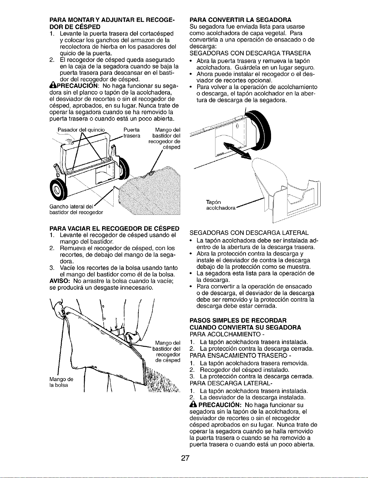
PARA MONTARY ADJUNTAR EL RECOGE-
DOR DE ClaSPED
1. Levante la puerta trasera del cortac_sped
y colocar los ganchos del armazon de la
recolectora de hierba en los pasadores del
quicio de la puerta.
2. El recogedor de c_sped queda asegurado
en la caja de la segadora cuando se baja la
puerta trasera para descansar en el basti-
_dor del recogedor de c_sped.
PRECAUCION: No haga funcionar su sega-
dora sin el planco o tap6n de la acolchadera,
el desviador de recortes o sin el recogedor de
c_sped, aprobados, en su lugar. Nunca trate de
operar la segadora cuando se ha removido la
puerta trasera o cuando est& un poco abierta.
Pasador del uincio Puerta
Mango del
bastidor del
recogedor de
c_sped
Gancho lateral del
bastidor del recogedor
PARA MACIAR EL RECOGEDOR DE ClaSPED
1. Levante el recogedor de c_sped usando el
mango del bastidor.
2. Remueva el recogedor de c_sped, con los
recortes, de debajo del mango de la sega-
dora.
3. Vacfe los recortes de la bolsa usando tanto
el mango del bastidor como 51de la bolsa.
AMISO: No arrastre ta bolsa cuando la vacfe;
se producir& un desgaste innecesario.
recogedor
de c_sped
Mango de
la bolsa
PARA CONVERTIR LA SEGADORA
Su segadora fue enviada lista para usarse
como acolchadora de capa vegetal. Para
convertirla a una operaci6n de ensacado o de
descarga:
SEGADORAS CON DESCARGA TRASERA
• Abra la puerta trasera y remueva la tap6n
acolchadora. Gu#,rdela en un lugar seguro.
• Ahora puede instalar el recogedor o el des-
viador de recortes opcional.
• Para volver a la operaci6n de acolchamiento
o descarga, el tap6n acolchador en la aber-
tura de descarga de la segadora.
\
Tap6n
SEGADORAS CON DESCARGA LATERAL
• La tap6n acolchadora debe ser instalada ad-
entro de la abertura de la descarga trasera.
• Abra la protecci6n contra la descarga y
instale et desviador de contra la descarga
debajo de la protecci6n como se muestra.
• La segadora esta lista para la operaci6n de
la descarga.
• Para convertir a la operaci6n de ensacado
o de descarga, et desviador de ta descarga
debe ser removido y la protecci6n contra la
descarga debe estar cerrada.
PASOS SIMPLES DE RECORDAR
CUANDO CONVIERTA SU SEGADORA
PARA ACOLCHAMIENTO -
1. La tap6n acolchadora trasera instalada.
2. La protecci6n contra ta descarga cerrada.
PARA ENSACAMIENTO TRASERO -
1. La tap6n acolchadora trasera removida.
2. Recogedor del c_sped instalado.
3. La protecci6n contra la descarga cerrada.
PARA DESCARGA LATERAL-
1. La tap6n acolchadora trasera instalada.
2. La desviador de la descarga instalada.
PRECAUCION: No haga funcionar su
segadora sin la tap6n de la acolchadora, el
desviador de recortes o sin el recogedor
c6sped aprobados en su lugar. Nunca trate de
operar la segadora cuando se halla removido
la puerta trasera o cuando se ha removido a
puerta trasera o cuando estA un poco abierta.
27
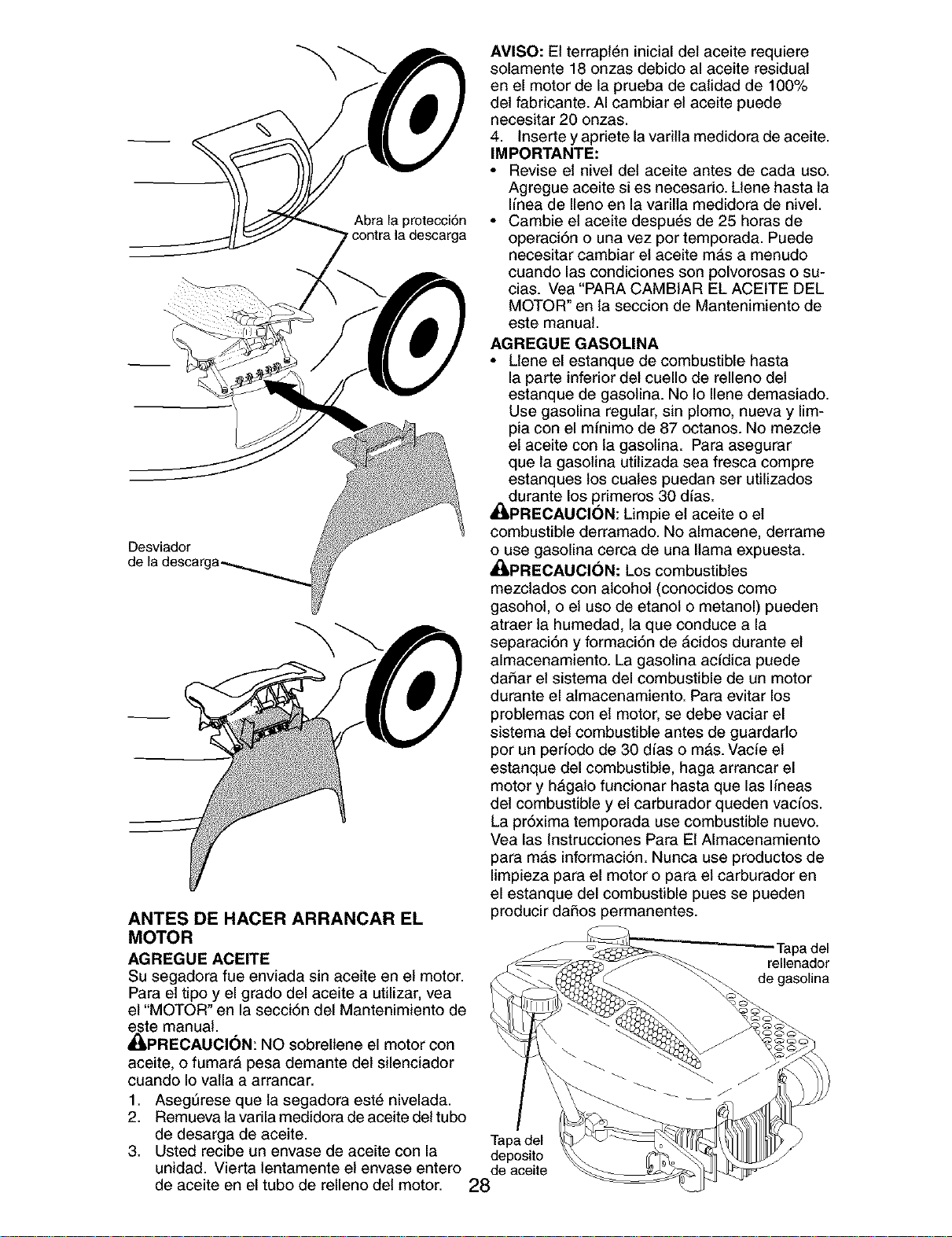
Abra la protecci6n
contra la descarga
Desviador
ANTES DE HACER ARRANCAR EL
MOTOR
AGREGUE ACEITE
Su segadora fue enviada sin aceite en el motor.
Para el tipo y el grado del aceite a utilizar, vea
el "MOTOR" en la secci6n del Mantenimiento de
este manual.
_PRECAUCI(_N: NO sobrellene el motor con
aceite, o fumar& pesa demante del silenciador
cuando Io valla a arrancar.
1. AsegSrese que la segadora est6 nivelada.
2. Remueva la varila medidora de aceite del tubo
de desarga de aceite.
3. Usted recibe un envase de aceite con la
unidad. Vierta lentamente el envase entero
de aceite en el tubo de relleno del motor.
Tapadel
deposito
de aceite
28
AVISO: El terrapl_n inicial del aceite requiere
solamente 18 onzas debido al aceite residual
en el motor de la prueba de calidad de 100%
del fabricante. AI cambiar el aceite puede
necesitar 20 onzas.
4. Inserte y apriete la varilla medidora de aceite.
IMPORTANTE:
• Revise el nivel del aceite antes de cada uso.
Agregue aceite si es necesario. Llene hasta la
Ifnea de Ileno en la varilla medidora de nivel.
• Cambie el aceite despu6s de 25 horas de
operaci6n o una vez pot temporada. Puede
necesitar cambiar el aceite m#,s a menudo
cuando las condiciones son polvorosas o su-
cias. Vea "PARA CAMBIAR EL ACEITE DEL
MOTOR" en la seccion de Mantenimiento de
este manual.
AGREGUE GASOLINA
• Llene el estanque de combustible hasta
la parte inferior del cuello de relleno del
estanque de gasolina. No Io Ilene demasiado.
Use gasolina regular, sin plomo, nueva y lim-
pia con el minimo de 87 octanos. No mezcle
el aceite con la gasolina. Para asegurar
que la gasolina utilizada sea fresca compre
estanques los cuates puedan ser utilizados
durante los p,rimeros 30 dfas.
_PRECAUCION: Limpie et aceite o el
combustible derramado. No almacene, derrame
o use gasolina cerca de una llama expuesta.
_PREOAUCION: Los combustibles
mezctados con alcohol (conocidos como
gasohol, o el uso de etanol o metanol) pueden
atraer la humedad, la que conduce a la
separaci6n y formaci6n de &cidos durante el
almacenamiento. La gasolina acfdica puede
daSar el sistema del combustible de un motor
durante el almacenamiento. Para evitar los
problemas con el motor, se debe vaciar el
sistema del combustible antes de guardado
por un periodo de 30 dfas o m&s. Vacie el
estanque del combustible, haga arrancar el
motor y h&galo funcionar hasta que las lineas
del combustible y el carburador queden vacfos.
La prSxima temporada use combustible nuevo.
Vea las Instrucciones Para Et Almacenamiento
para mAs informaci6n. Nunca use productos de
limpieza para el motor o para el carburador en
el estanque del combustible pues se pueden
producir daSos permanentes.
apa del
rellenador
de gasolina
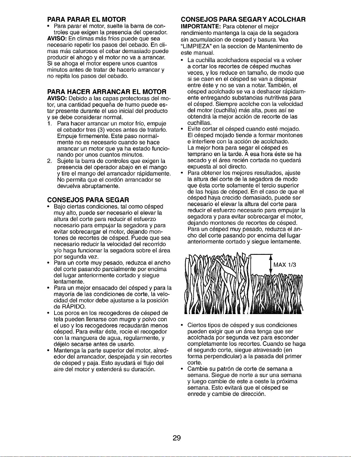
PARA PARAR EL MOTOR
• Para parar el motor, suelte la barra de con-
troles que exigen la presencia del operador.
AMISO: En climas mAs frios puede que sea
necesado repetir los pasos del cebado. En cli-
mas mAs calurosos el cebar demasiado puede
producir el ahogo y el motor no va a arrancar.
Si se ahoga el motor espere unos cuantos
minutos antes de tratar de hacerlo arrancar y
no repita los pasos del cebado.
PARA HACER ARRANCAR EL MOTOR
AVISO: Debido alas capas protectoras del mo-
tor, una cantidad pequeSa de humo puede es-
tar presente durante el uso inicial del producto
y se debe considerar normal.
1. Para hacer arrancar un motor frfo, empuje
el cebador tres (3) veces antes de tratarlo.
Empuje firmemente. Este paso normal-
mente no es necesario ouando se hace
arrancar un motor que ya ha estado funcio-
nando por unos cuantos minutos.
2. Sujete la barra de controles que exigen la
presencia del operador abajo en el mango
y tire el mango del arrancador rapidamente.
No permita que el cord6n arrancador se
devuelva abruptamente.
CONSEJOS PARA SEGAR
• Bajo ciertas condiciones, tal como c_sped
muy alto, puede ser necesado el elevar la
altura del corte para reducir el esfuerzo
necesario para empujar la segadora y para
evitar sobrecargar el motor, dejando mon-
tones de recortes de c_sped. Puede que sea
necesario reducir la velocidad del recorrido
y/o haga funcionar la segadora sobre el Area
por segunda vez.
• Para un corte muy pesado, reduzca el ancho
del corte pasando parcialmente por encima
del lugar anteriormente cortado y siegue
lentamente.
• Para un mejor ensacado del c_sped y para la
mayoria de tas condiciones de corte, la velo-
cidad del motor debe ajustarse a la posici6n
de R_,PIDO.
• Los poros en los recogedores de c6sped de
tela pueden llenarse con mugre y polvo con
el uso y los recogedores recaudarAn menos
c6sped. Para evitar 6ste, rocie el recogedor
con la manguera de agua, regularmente, y
d6jelo secarse antes de usarlo.
• Mantenga ta parte superior del motor, alred-
edor del arrancador, despejada y sin recortes
de c_sped y paja. Esto ayudarA el flujo del
aire del motor y extendera su duraci6n.
CONSEJOS PARA SEGARY ACOLCHAR
IMPORTANTE: Para obtener el mejor
rendimiento mantenga la caja de la segadora
sin acumulacion de cesped y basura. Vea
"LIMPIEZA" en la seccion de Mantenimento de
este manual.
• La cuchilla acolchadora especial va a volver
a cortar los recortes de c_sped muchas
veces, y los reduce en tamaSo, de modo que
si se caen en el c6sped se van a dispesar
entre 6ste y no se van a notar. Tambi6n, el
c_sped acolchado se va a deshacer rApidam-
ente entregando substancias nutritivas para
el c6sped. Siempre acolche con la vetocidad
del motor (cuchilla) mAs alta, pues asf se
obtendrA la mejor acci6n de recorte de las
cuchillas.
• Evite cortar el c_sped cuando est6 mojado.
El c6sped mojado tiende a formar montones
e interfiere con la acci6n de acolchado.
La mejor hora para segar el c_sped es
temprano en la tarde. A esa hora 6ste se ha
secado y el Area reci6n cortada no quedarA
expuesta al sol directo.
• Para obtener los mejores resultados, ajuste
la altura del corte de ta segadora de modo
que _sta corte solamente el tercio superior
de las hojas de c_sped. En el caso de que el
c_sped haya crecido demasiado, puede ser
necesario el elevar la altura del corte para
reducir el esfuerzo necesado para empujar la
segadora y para evitar sobrecargar el motor,
dejando montones de recortes de c_sped.
Para un c_sped muy pesado, reduzca el an-
cho del corte pasando por encima del lugar
anteriormente cortado y siegue lentamente.
• Ciertos tipos de c6sped y sus condiciones
pueden exigir que un Area tenga que set
acolchada por segunda vez para esconder
completamente los recortes. Cuando se haga
el segundo corte, siegue atravesado (en
forma perpendicular) a la pasada del primer
corte.
• Cambie su patr6n de corte de semana a
semana. Siegue de norte a sur una semana
y luego cambie de este a oeste ta pr6xima
semana. Esto evitarA que el c_sped se
enrede y cambie de direcci6n.
29
PROGRAMA DE CADA A.TESDEL
MANTENIMIENTO DEUSOCADA TEMPORADA2S.ORASO ALMACE-
ES Umpiad]nspeccionar el RecogedordeC_sped *
Controlar tos Neum_ticos
Controlar tas Ruedas Mortices ***
Umpiar la Segadora .... V p
D Umpiar debajo la Cubierta de la TransmisiSn ***
Revisar las Correas y las Poteas Impulsadas *** •Jr
Revisar / Afitar / Cambiar la Cuchilta
Lubricaci6n
Umpiar / Recargar la Bateria ** _
Revisar el nivel del Aceite
_ ambiar el Aceite del motor _2
Umpiar el Filtro de Aire
T Inspeccionar el Silenciador
Cambiar la Bujia _#2
R Cambiar el Cartucho de Papel des FiStrode Aire
Vaciar el sistema del carburante =J
o aSadir un estabilizador de carburante.
* (si viene equipado) 1 - Cambiar rnds a menudo cuando se opere bajo carga pesada o en ambientes con altas temperatures.
** Segadoras con Arranque El_,t dco 2 - Dar servido mds a menudo cuando se opere en condiciones sucias o polvorosas.
*** Sagadoras con Poder Pmpulsor 3 - Cambie las c_Jchillasrn_s a menudo cuando siegue en terreno arenoso.
**** U_lizar una rasquata para limpiar 4 - Cargar por 48 horas al fin de la temporada.
debaJode lacublarta del cortacdsped 5 - Y despuds de 5 horns de fgncionarnierdo.
RECOMENDACIONES GENERALES
La garantia de esta segadora no cubre los
articulos que han estado sujetos at abuso o a
la negligencia del operador. Para recibir todo
el valor de la garantia, el operador tiene que
mantener la segadora seg=3nlas instrucciones
descritas en este manual.
TABLA DE LUBRICAClON
(_) Aceite del motor
Hay algunos ajustes que se tienen que hacer
en forma periSdica para poder mantener su
unidad adecuadamente.
AI menos una vez cada estaciSn comprobar
si es necesario efectuar los ajustes descritos
en las secciones de Servicio y Ajustes de este
manual.
• Una vez al aSo, cambie la bujia, limpie o
cambie el elemento del filtro de aire y revise
si la cuchilla est& desgastada. Una bujia
nueva y un elemento del filtro de aire limpio/
nuevo aseguran la mezcla de aire-com-
bustible adecuada y ayudan a que su motor
funcione mejor y que dure m_,s.
• Siga el programa de mantenimiento en este
manual.
ANTES DE CADA USO
• Revise el nivel del aceite del motor.
• Revise si hay sujetadores sueltos.
LUBRICACI(_N
Mantenga la unidad bien lubricada
(vea la "TABLA DE LUBRICACION").
I
I
I
(_ Puntal de
resorte del
freno
(_ Bisagra de
la puerta de la
-,) acolchadora
"(_ Bisagra de la
puerta traser
(_ Clavija de montaje del puntal del mango
(_ Rocie el lubricante
(_ Vea "MOTOR" en la seccion de Mantenimiento
IMPORTANTE: No aceite o engrase los roda-
mientos de la rueda de plastico. Los lubricantes
viscosos atearan polvo y mugre, lo acortara la
duracion de los rodamientos autolubdcantes. Si
cree que tienen que lubricarse, use losamente
un lubricante tipo crafito, de polvo seco, en
forma moderada.
30
SEGADORA
Siempre observe las reglas de seguridad cu-
ando haga el mantenimiento.
LLANTAS
• Mantenga las llantas sin gasolina, aceite o
substancias qufmicas para control de insec-
tos que pueden dai_ar la goma.
• Evite los tocones, las piedras, las gdetas pro-
fundas, los objetos afilados y otros peligros
que pueden da_ar alas Ilantas.
RUEDAS DE IMPULSION
Revise las ruedas de impulsi6n traseras cada
vez antes de segar, para asegurarse de que se
mueven libremente. Si las ruedas no giran li-
bremente quiere decir que hay basura, recortes
de c_sped, etc. dentro del Area de las ruedas
de impulsi6n y de la cubierta contra el polvo y
tienen que limpiarse para liberarlas.
Es necesario limpiar las ruedas de impulsi6n;
revise ambas ruedas traseras.
CUIDADO DE LA CUCHILLA
Para obtener los mejores resultados, la cuchilla
de la segadora tienen que mantenerse afilada.
Cambie la cuchilla doblada o daSada.
PARA REMOVER LA CUCHILLA
1. Desconecte el alambre de la bujfa y p6ngalo en
donde no pueda entrar en contacto con 6sta.
2. Haga descansar la segadora en su lado.
AsegSrese que el filtro de aire y que et
carburador queden mirando hacia ardba.
3. Use un bloque de madera entre la cuchilla
y la caja de la segadora para evitar que la
cuchilla gire cuando sete quite el perno.
AVISO: Proteja sus manes con guantes y/o
envuelva la cuchilla con una tela gruesa.
4. Remueva el perno de la cuchilla girAndolo
en el sentido contrado en que giran las
manillas del reloj.
5. Remueva la cuchilla y los artfculos de fer-
reterfa adjuntadores (el perno, la arandela
de seguddad y la arandela endurecida).
AVISO: Remueva el adaptador de la cuchilla y
revise el cubo interior de la ranura del adaptador
de la cuchilla. La ranura tiene que estar en
buenas condiciones para que funcione en forma
adecuada. Cambie el adaptador si estA daSado.
PARA CAMBIAR LA CUCHILLA
1. Ponga el adaptador de la cuchilla en el
cigueSal del motor. Asegt]rese que la ranura
det adaptador y que el chavetero del cigue-
5al est_n alineados.
2. Ponga la cuchilla en el adaptador de _sta
alineando los dos (2) agujeros en la cuchilla
con tas salientes elevadas en el adaptador.
3. AsegSrese de que el borde de salida de
la cuchilla (opuesto al borde afilado) est6
hacia arriba hacia el motor.
4. Instale el perno de la cuchilla con la aran-
dela de seguddad y la arandela endurecida
en el adaptador de la cuchilla y el cigueSaL
5. Use un bloque de madera entre la cuchilla
y la caja de la segadora y apriete el perno
de la cuchilla girAndolo en el sentido en que
giran las manillas det reloj.
• La torsi6n para apretar recomendada es de
35 - 40 pies libras.
IMPORTANTE: El perno de la cuchilla es
tratado a calo. Si es necesario sustituir los
pemos, sustituirlos s61ocon pernos aprobados
mostrados en la secci6n Partes de Reparaci6n
de este manual.
31
Ranura_-_
Arandela de se
Cuchilla
z ciguenal
P rn Arandela
e o
de la endurecida J_nal
cuchilla Borde de salida Adaptador de la cuchilla
PARA AFILAR LA CUCHILLA
AVISO: No recomendamos el afilar la cuchilla
- pero si Io hace, asegt]rese de que quede
batanceada. Se tiene que tener cuidado de
manteneda batanceada. Una cuchilla que no
estA batanceada va a producir eventualmente
daSo en la segadora o en el motor.
• La cuchilla puede afilarse con una lima o en
una rueda rectificadora. No trate de afilarla
mientras se encuentra en la segadora.
• Para revisar el balance de la cuchilla, clave
un clavo en una viga o en la pared. Deje
alrededor de una pulgada de un clavo recto
expuesto. Ponga el agujero central de la
cuchilla sobre la cabeza del clavo. Si ta
cuchilla estA balanceada debe permanecer
en la posici6n horizontal. Si cualquiera de
los extremos de la cuchilla se mueve hacia
abajo, afile et extremo pesado hasta que 6sta
quede balanceada.
RECOGEDOR DE ClaSPED
• El recogedor de c6sped puede ser rociado
con el agua de la manguera pero tiene que
estar seco cuando se vaya a usar.
• Revise su recogedor de c_sped a menudo
para verificar si estA daSado o deteriorado.
Se va a desgastar con el uso normal. Si se
necesita cambiar el recogedor, cambielo
solamente por uno que sea aprobado por el
fabricante. D_ el nt_mero del modelo de la
segadora cuando Io ordene.
CAJA DE ENGRANAJES
• Para mantener el sistema de impulsi6n
funcionando en forma adecuada, la caja
de engranajes y el Area alrededor de la
impulsi6n tienen que mantenerse limpias y
sin acumulaci6n de basura. Limpie debajo
de la cubierta de la impulsi6n dos veces por
temporada.
• La caja de engranajes se llena con lubdcante
hasta el nivel adecuado en la fabric& La
t]nica vez que el lubricante necesita atenci6n
es cuando se le ha prestado servicio a la
caja de engranajes.
• Si se necesita lubdcante, use sotamente
Grasa Texaco Starplex Premium 1, Parte No.
750369. No use substitutos.
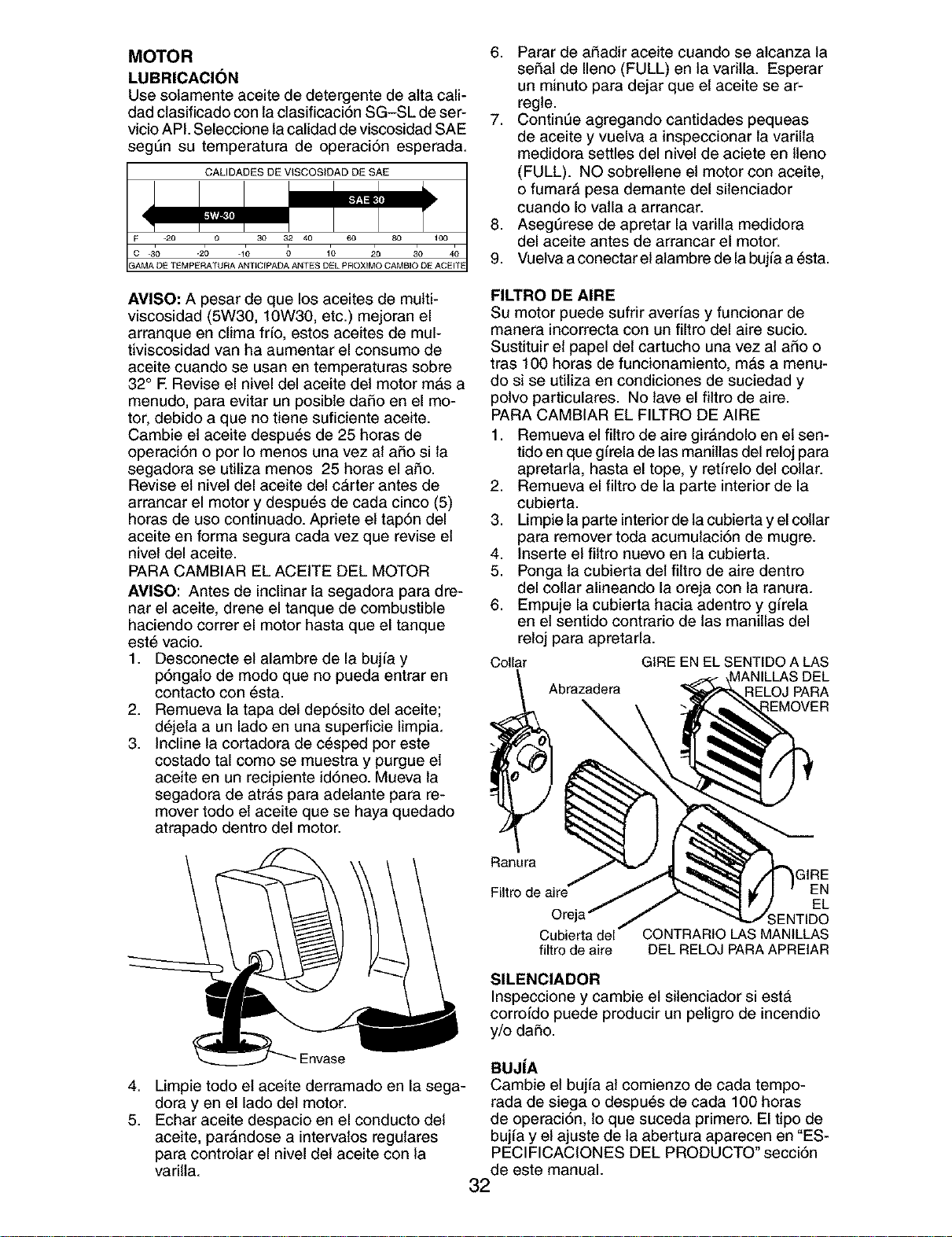
MOTOR
LUBRICACI(_N
Use solamente aceite de detergente de atta call-
dad clasificado con la ctasificaci6n SG-SL de ser-
vicioAPI. Seleccione la calidad de viscosidadSAE
seg_n su temperatura de operaci6n esperada.
6. Parar de aSadir aceite cuando se alcanza la
seSal de Ileno (FULL) en la varilla. Esperar
un minute para dejar que el aceite se ar-
regle.
7. Contint]e agregando cantidades pequeas
de aceite y vuelva a inspeccionar la varilla
medidora settles del nivel de aciete en Ileno
(FULL). NO sobrellene el motor con aceite,
o fumarA pesa demante del silenciador
cuando Io vatla a arrancar.
8. Asegt_rese de apretar la varilla medidora
del aceite antes de arrancar el motor.
9. Vuelva aconectar el alambre de la bujfa a 6sta.
AVISO: A pesar de que los aceites de multi-
viscosidad (5W30, 10W30, etc.) mejoran el
arranque en clima frfo, estos aceites de mul-
tiviscosidad van ha aumentar el consumo de
aceite cuando se usan en temperaturas sobre
32° E Revise el nivel del aceite del motor mas a
menudo, para evitar un posible daSo en el mo-
tor, debido a que no tiene suficiente aceite.
Cambie el aceite despu6s de 25 horas de
operaci6n o por Io menos una vez al aSo si la
segadora se utiliza menos 25 horas el aSo.
Revise el nivet del aceite del c&rter antes de
arrancar el motor y despu6s de cada cinco (5)
horas de uso continuado. Apriete el tap6n del
aceite en forma segura cada vez que revise el
nivel del aceite.
PARA CAMBIAR EL ACEITE DEL MOTOR
AMISO: Antes de inclinar la segadora para dre-
nar el aceite, drene el tanque de combustible
haciendo correr el motor hasta que el tanque
est_ vacio.
1. Desconecte el alambre de la bujfa y
p6ngato de modo que no pueda entrar en
contacto con 6sta.
2. Remueva la tapa del dep6sito del aceite;
d6jela a un lade en una superficie limpia.
3. Incline la cortadora de c_sped por este
costado tal como se muestra y purgue el
aceite en un recipiente id6neo. Mueva la
segadora de atrAs para adelante para re-
mover todo el aceite que se haya quedado
atrapado dentro del motor.
FILTRO DE AIRE
Su motor puecte sufrir averfas y funcionar de
manera incorrecta con un filtro del aire sucio.
Sustituir et papel del cartucho una vez al aSo o
tras 100 horas de funcionamiento, m&s a menu-
do si se utiliza en condiciones de suciedad y
polvo particulares. No lave el filtro de aire.
PARA CAMBIAR EL FILTRO DE AIRE
1. Remueva el filtro de aire girAndolo en el sen-
tide en que gffela de las manillas del reloj para
apretarla, hasta el tope, y retffelo del collar.
2. Remueva el filtro de la parte interior de la
cubierta.
3. Limpie la parte interior de la cubierta y el collar
para remover toda acumulaci6n de mugre.
4. Inserte el filtro nuevo en la cubierta.
5. Ponga la cubierta del filtro de aire dentro
del collar alineando la oreja con ta ranura.
6. Empuje la cubierta hacia adentro y girela
en el sentido contrario de las manillas del
reloj para apretarla.
Collar GIRE EN EL SENTIDO ALAS
MANILLAS DEL
Abrazadera RELOJ PARA
{EMOVER
Ranura
_IRE
Filtro de aire EN
EL
;ENTIDO
Cubierta del CONTRARtO LAS MANILLAS
filtro de aire DEL RELOJ PARA APREIAR
SlLENClADOR
Inspeccione y cambie et silenciador si est&
corroido puede producir un peligro de incendio
y/o daSo.
4.
5.
Limpie todo el aceite derramado en la sega-
dora yen el lado del motor.
Echar aceite despacio en el conducto del
aceite, par&ndose a intervalos regulares
para controlar el nivel del aceite con la
varilla.
BUJ|A
Cambie et bujia at comienzo de cada tempo-
rada de siega o despu@s de cada 100 horas
de operaci6n, 1oque suceda primero. El tipo de
bujia y el ajuste de la abertura aparecen en "ES-
PECIFICACIONES DEL PRODUCTO ° secci6n
de este manual.
32
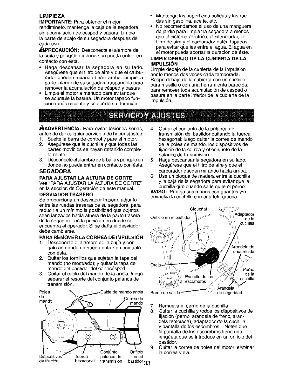
LIMPIEZA
IMPORTANTE: Para obtener el mejor
rendimineto, mantenga ta caja de la segadora
sin acumulacion de cesped y basura. Limpie
la parte de abajo de su segadora despues de
cada uso.
Ai:_PRECAUOI(_N: Desconecte el alambre de
la bujia y p6ngalo en donde no pueda entrar en
contacto con 6sta.
• Haga descansar la segadora en su lado.
Aseg0rese que el filtro de abe y que el carbu-
rador queden mirando hacia arriba. Limpie la
parte inferior de su segadora rasp&ndola para
remover la acumulaci6n de c_sped y basura.
• Limpie el motor a menudo para evitar que
se acumule la basura. Un motor tapado fun-
ciona m&s caliente y se acorta su duraci6n.
• Mantenga las superficies pulidas y las rue-
das sin gasolina, aceite, etc.
• No recomendamos el uso de una manguera
de jardfn para limpiar la segadora a menos
que el sistema el_ctrico, el silenciador, el
filtro de abe y el carburador est6n tapados
para evitar que les entre el agua. El agua en
el motor puede acortar la duraci6n de _ste.
LIMPIE DEBAJO DE LA CUBIERTA DE LA
IMPULSI(_N
Limpie debajo de la cubierta de la impulsi6n
por Io menos dos veces cada temporada.
Raspe debajo de la cubierta con un cuchillo
para masilla o con una herramienta parecida,
para remover toda acumulaci6n de c_sped o
basura en la parte inferior de la cubierta de la
impulsi6n.
_I_ADVERTENCIA: Para evitar lesi6nes serias,
antes de dar calquier service o de hacer ajustes:
1. Suelte la barra de control y pare el motor.
2. Aseg0rese que la cuchilla y que todas las
partes movibles se hayan detenido comple-
tamente.
3. Desconecte el alambre de la bujia y p6ngalo en
donde no pueda entrar en contacto con _sta.
SEGADORA
PARA AJUSTAR LA ALTURA DE CORTE
Vea "PARA AJUSTAR LA ALTURA DE CORTE"
en la secci6n de Operaci6n de este manual.
DESVIADOR TRASERO
Se proporciona un desviador trasero, adjunto
entre las ruedas traseras de su segadora, para
reducir a un minimo ta posibilidad que objetos
sean lanzados hacia afuera de la parte trasera
de la segadora, en ta posici6n en donde se
encuentra el operador. Si se daSa el desviador
debe cambiarse.
PARA REMOVER LA CORREA DE IMPULSION
1. Desconecte el alambre de la bujfa y p6n-
galo en donde no pueda entrar en contacto
con 6sta.
2. Quitar los tornillos que sujetan la tapa del
mando (no mostrado); y quitar la tapa del
mando del bastidor del cortac_sped.
3. Quitar el cable del mando de la ancla, luego
separar el resorte del conjunto patanca de
transmisi6n.
Polea de mando ancla
de
mando mando
de fijaci6n
4. Quitar el conjunto de la palanca de
transmisi6n del bastidor quitando la tuerca
hexagonal; luego quitar la correa de mando
de la polea de mando, los dispositivos de
fijaci6n de la correa y el conjunto de la
palanca de transmisi6n.
5. Haga descansar la segadora en su lade.
Aseg0rese que el filtro de abe y que el
carburador queden mirando hacia arriba.
6. Use un bloque de madera entre la cuchilla
y la caja de la segadora para evitar que la
cuchilla gire cuando se le quite el perno.
AVISO: Proteja sus manos con guantes y/o
envuelva la cuchilla con una tela gruesa.
Orificioen
Cigue5al
Arandela
Borde de salida de seguridad
de la
cuchilla
_,randela de
endurecida
7,
8.
Perno
de la
cuchilla
g,
Conj_nto Orificio
Tuerca palancade en el
hexagonal transmisi6n bastidor33
Remueva el perno de la cuchilla.
Quitar la cuchilla y todos los dispositivos de
fijaci6n (perno, arandela de freno, aran-
dela templada), adaptador de la cuchilla
y pantalia de los escombros. Noten que
la pantalla de los escombros tiene una
lengeeta que se introduce en un orificio del
bastidor.
Quitar la correa de polea del motor; eliminar
la correa vieja.
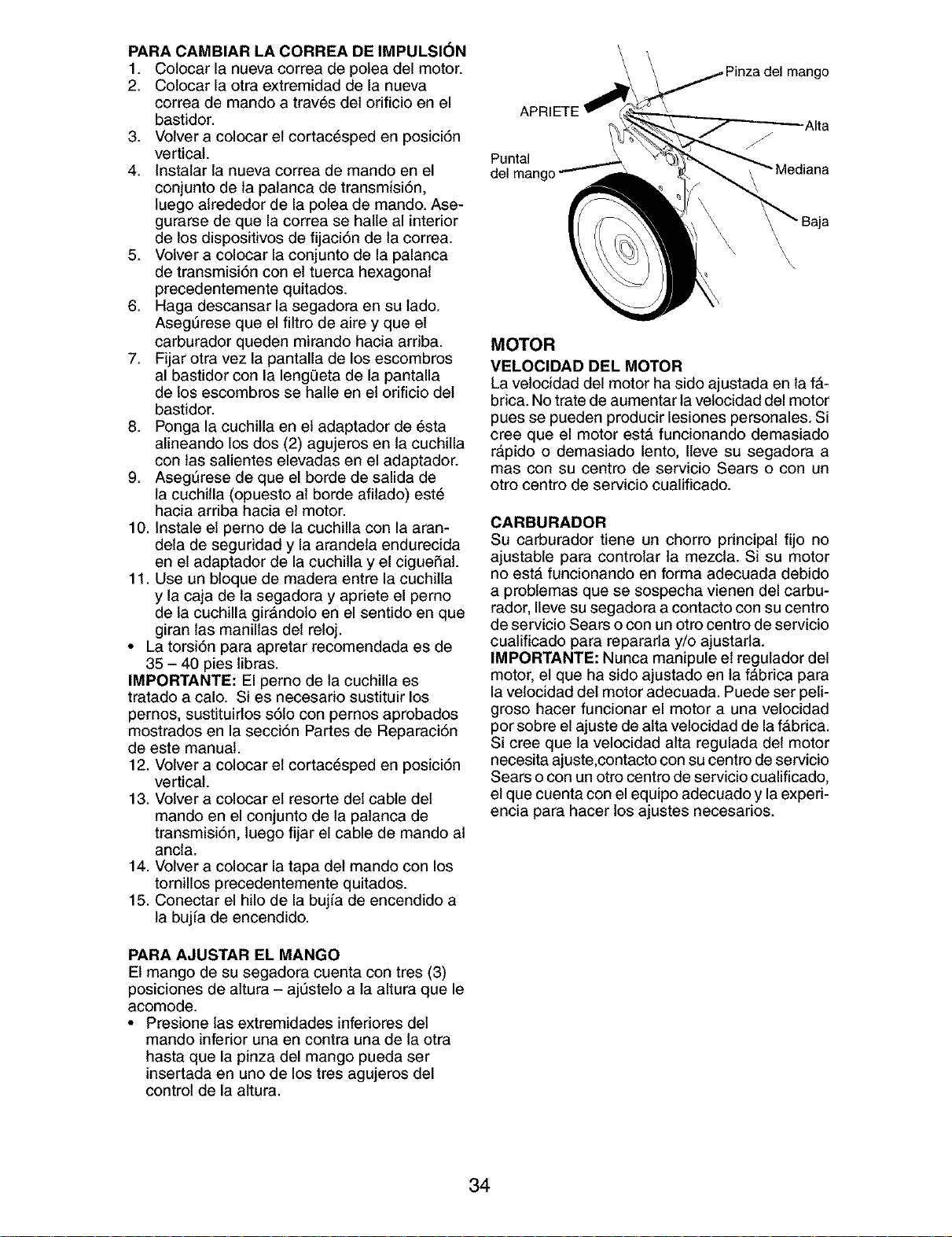
PARA CAMBIAR LA CORREA DE IMPULSI(_N
1. Colocar la nueva correa de polea del motor.
2. Colocar la otra extremidad de la nueva
correa de mando a trav6s del orificio en el
bastidor.
3. Volver a colocar el cortac6sped en posici6n
vertical.
4. Instalar la nueva correa de mando en el
conjunto de la patanca de transmisi6n,
luego alrededor de la polea de mando. Ase-
gurarse de que la correa se halle al interior
de los dispositivos de fijaci6n de la correa.
5. Volver a colocar la conjunto de la palanca
de transmisi6n con el tuerca hexagonal
precedentemente quitados.
6. Haga descansar la segadora en su lado.
AsegSrese que el filtro de aire y que el
carburador queden mirando hacia ardba.
7. Fijar otra vez la pantalla de los escombros
al bastidor con la leng0eta de la pantalla
de los escombros se halle en el orificio del
bastidor.
8. Ponga la cuchilla en el adaptador de _sta
alineando los dos (2) agujeros en la cuchilla
con tas salientes elevadas en el adaptador.
9. AsegSrese de que el borde de salida de
la cuchilla (opuesto al borde afilado) est6
hacia arriba hacia el motor.
10. Instale el perno de la cuchilla con la aran-
dela de seguddad y la arandela endurecida
en el adaptador de la cuchilla y el cigueSaL
11. Use un bloque de madera entre la cuchilla
y la caja de la segadora y apriete el perno
de la cuchilla gir#,ndolo en el sentido en que
giran las manillas det reloj.
• La torsi6n para apretar recomendada es de
35 - 40 pies libras.
IMPORTANTE: El perno de la cuchilla es
tratado a calo. Si es necesario sustituir los
pernos, sustituirlos s6to con pernos aprobados
mostrados en la secci6n Partes de Reparaci6n
de este manual.
12. Volver a colocar el cortac6sped en posici6n
vertical.
13. Volver a colocar el resorte del cable del
mando en el conjunto de la patanca de
transmisi6n, luego fijar el cable de mando al
ancla.
14. Volver a colocar la tapa del mando con los
tornillos precedentemente quitados.
15. Conectar el hilo de la bujfa de encendido a
la bujfa de encendido.
PARA AJUSTAR EL MANGO
El mango de su segadora cuenta con tres (3)
posiciones de altura - ajt]stelo a la altura que le
acomode.
• Presione las extremidades infedores del
mando inferior una en contra una de ta otra
hasta que la pinza del mango pueda ser
insertada en uno de los tres agujeros del
control de la altura.
Puntal
Baja
\
MOTOR
VELOCIDAD DEL MOTOR
La vetocidad del motor ha sido ajustada en la f#,-
bdca. No trate de aumentar la velocidad del motor
pues se pueden producir lesiones personales. Si
cree que el motor est#, funcionando demasiado
r&pido o demasiado lento, Ileve su segadora a
mas con su centro de servicio Sears o con un
otro centro de servicio cualificado.
CARBURADOR
Su carburador tiene un chorro principal fijo no
ajustable para controlar la mezcla. Si su motor
no est#, funcionando en forma adecuada debido
a problemas que se sospecha vienen del carbu-
rador, Ileve su segadora a contacto con su centro
de servicio Sears o con un otro centro de servicio
cuatificado para repararla y/o ajustarla.
IMPORTANTE: Nunca manipule el regulador del
motor, el que ha sido ajustado en la f&brica para
la velocidad del motor adecuada. Puede ser peli-
groso hacer funcionar el motor a una velocidad
por sobre el ajuste de atta velocidad de la f#,brica.
Si cree que la velocidad alta regulada del motor
necesita ajuste,contacto con su centro de servicio
Sears o con un otro centro de servicio cualificado,
el que cuenta con el equipo adecuado y la experi-
encia para hacer los ajustes necesarios.
34
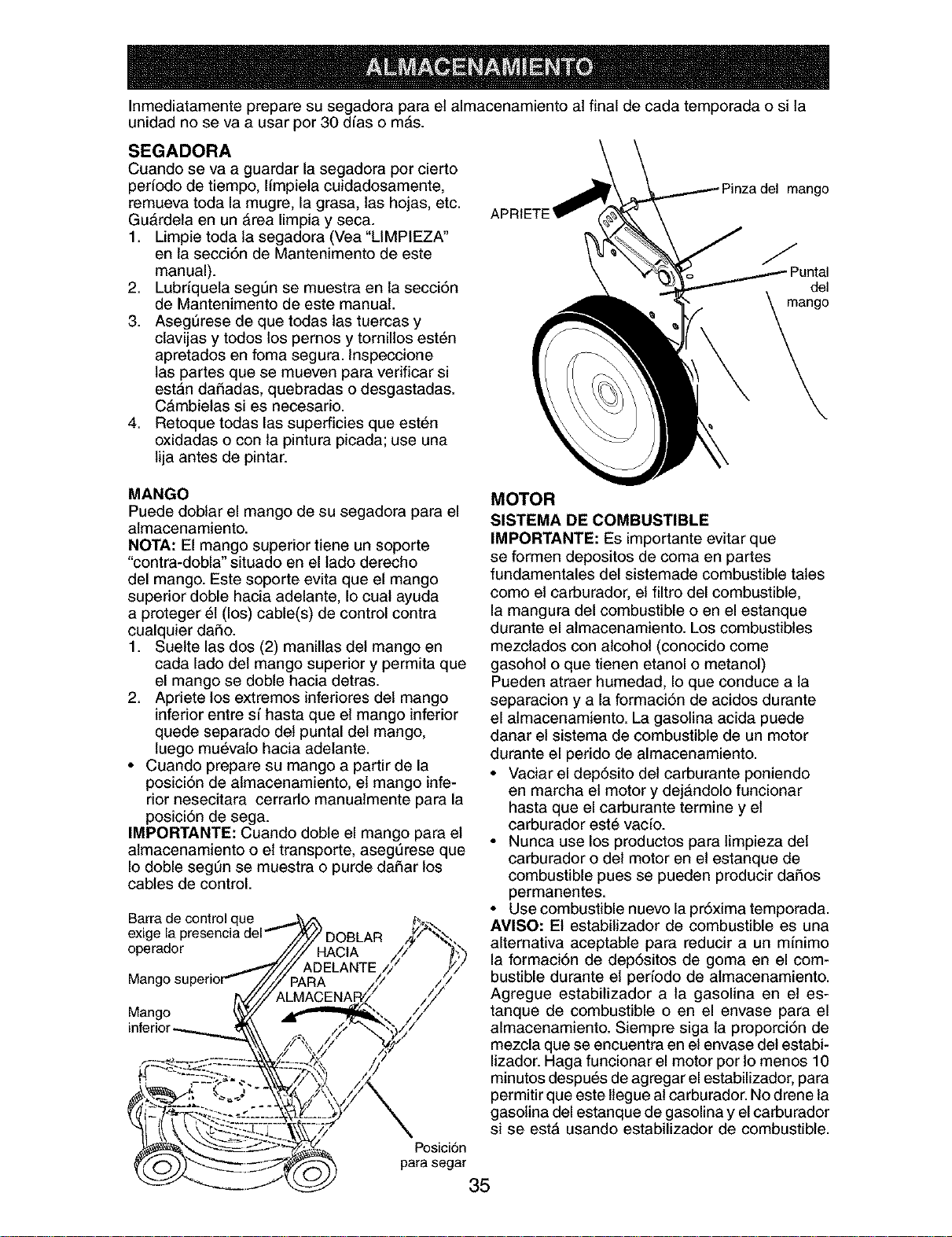
Inmediatamente prepare su segadora para el almacenamiento al final de cada temporada o si la
unidad no se va a usar per 30 dias o m&s.
SEGADORA
Cuando se va a guardar la segadora por cierto
periodo de tiempo, limpiela cuidadosamente,
remueva toda la mugre, la grasa, las hojas, etc.
GuArdeta en un &rea limpia y seca.
1. Limpie toda ta segadora (Vea "LIMPIEZA"
en ta secci6n de Mantenimento de este
manual).
2. Lubriquela seg_n se muestra en la secci6n
de Mantenimento de este manual.
3. Aseg_rese de que todas las tuercas y
ctavijas y todos los pernos y tornillos est6n
apretados en foma segura. Inspeccione
las partes que se mueven para vedficar si
estan dai_adas, quebradas o desgastadas.
C&mbielas si es necesado.
4. Retoque todas las superficies que est6n
oxidadas o con la pintura picada; use una
lija antes de pintar.
mango
del
MANGO
Puede doblar el mango de su segadora para el
almacenamiento.
NOTA: El mango superior tiene un soporte
"contra-dobla" situado en el lado derecho
del mango. Este soporte evita que el mango
superior doble hacia adelante, Io cual ayuda
a proteger 61(los) cable(s) de control contra
cualquier daSo.
1. Suelte las dos (2) manillas del mango en
cada lado del mango superior y permita que
el mango se doble hacia detras.
2. Apdete los extremes inferiores del mango
inferior entre s[ hasta que el mango inferior
quede separado det puntal del mango,
luego mu_valo hacia adelante.
• Cuando prepare su mango a partir de la
posici6n de almacenamiento, el mango infe-
rior nesecitara cerrado manuatmente para la
posici6n de sega.
IMPORTANTE: Cuando doble el mango para el
almacenamiento o el transporte, asegt_rese que
Io doble segt]n se muestra o purde daSar los
cables de control.
tue
operador
Mango
MOTOR
SISTEMA DE COMBUSTIBLE
IMPORTANTE: Es importante evitar que
se formen depositos de coma en partes
fundamentales del sistemade combustible tales
como el carburador, el filtro del combustible,
la mangura del combustible o en el estanque
durante el atmacenamiento. Los combustibles
mezclados con alcohol (conocido come
gasohol o que tienen etanol o metanol)
Pueden atraer humedad, Io que conduce a la
separacion y a la formaci6n de acidos durante
el almacenamiento. La gasolina acida puede
danar el sistema de combustible de un motor
durante el perido de almacenamiento.
• Vaciar el dep6sito del carburante poniendo
en marcha el motor y dej&ndolo funcionar
hasta que el carburante termine y el
carburador est6 vacio.
• Nunca use los productos para limpieza del
carburador o del motor en el estanque de
combustible pues se pueden producir daiSos
permanentes.
• Use combustible nuevo la pr6xima temporada.
AVlSO: El estabilizador de combustible es una
alternativa aceptable para reducir a un minimo
la formaci6n de dep6sitos de goma en el com-
bustible durante el perfodo de almacenamiento.
Agregue estabilizador a la gasolina en et es-
tanque de combustible o en el envase para el
almacenamiento. Siempre siga la proporci6n de
mezcla que se encuentra en el envase del estabi-
lizador. Haga funcionar el motor por Io menos 10
minutes despu6s de agregar el estabilizador, para
permitir que este tlegue al carburador. No drene la
gasolina del estanque de gasolina y el carburador
si se est4 usando estabilizador de combustible.
Posici6n
para segar
35
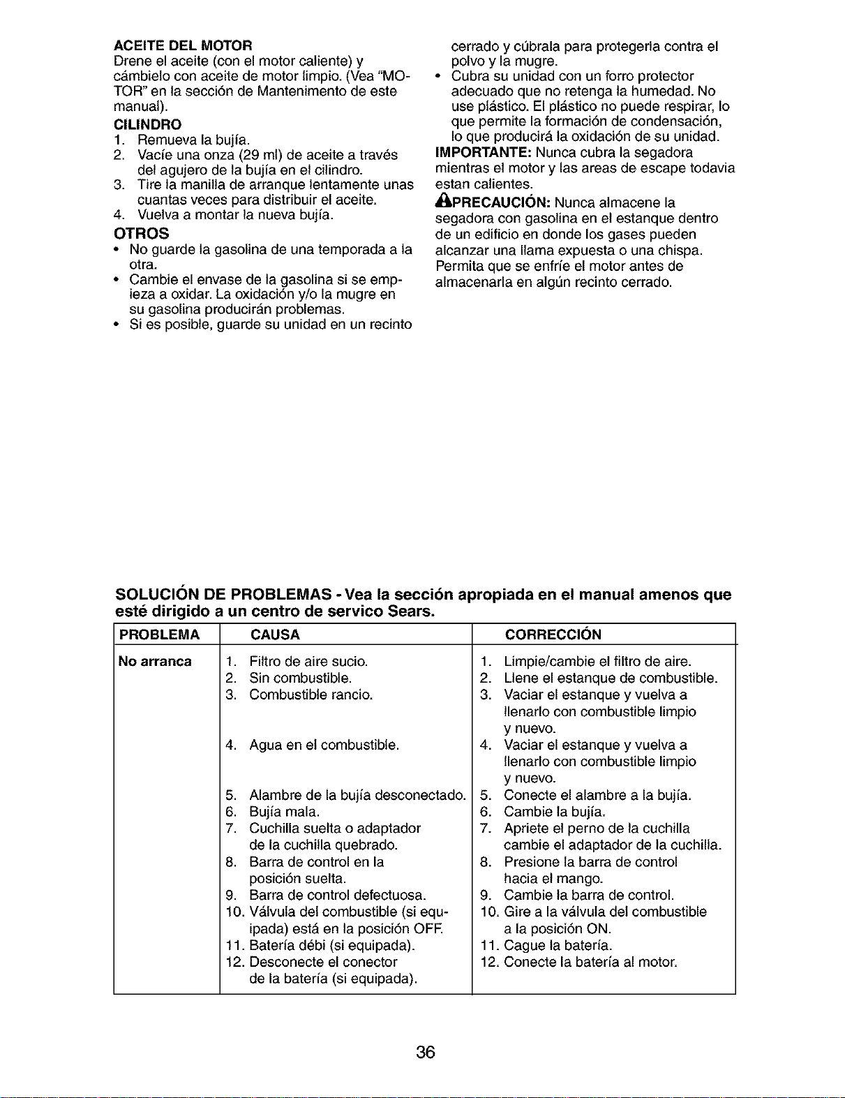
ACEITE DEL MOTOR
Drene el aceite (con el motor caliente) y
c&mbielo con aceite de motor limpio. (Vea "MO-
TOR" on la secci6n de Mantenimento de este
manual).
ClLINDRO
1. Remueva la bujfa.
2. Vacfe una onza (29 ml) de aceite a tray,s
del agujero de la bujfa on el cilindro.
3. Tire la manilla de arranque lentamente unas
cuantas veces para distribuir el aceite.
4. Vuelva a montar la nueva bujfa.
OTROS
• No guarde la gasolina de una temporada a la
otra.
• Cambie el envase de la gasolina si se emp-
ieza a oxidar. La oxidaci6n y/o la mugre en
su gasolina producir&n problemas.
• Si es posible, guarde su unidad en un recinto
cerrado y ct]brala para protegerla contra el
polvo y la mugre.
• Cubra su unidad con un forro protector
adecuado que no retenga la humedad. No
use pl_,stico. El pl_stico no puede respirar, Io
que permite la formaci6n de condensaci6n,
Io que producir#, ta oxidaci6n de su unidad.
IMPORTANTE: Nunca cubra la segadora
mientras el motor y las areas de escape todavia
estan catientes.
_kPRECAUCI(_N: Nunca atmacene la
segadora con gasolina en el estanque dentro
de un edificio en donde los gases pueden
alcanzar una llama expuesta o una chispa.
Permita que se enfrfe el motor antes de
almacenarla en atg=3nrecinto cerrado.
SOLUCION DE PROBLEMAS - Vea la secci6n apropiada en el manual amenos que
est_ dirigido a un centro de servico Sears.
PROBLEMA CAUSA
No arranca 1. Filtro de aire sucio.
2. Sin combustible.
3. Combustible rancio.
4. Agua en el combustible.
5. Alambre de la bujia desconectado.
6. Bujia mala.
7. Cuchilla suelta o adaptador
de la cuchilla quebrado.
8. Barra de control en la
posici6n suelta.
9. Barra de control defectuosa.
10. V_,lvula del combustible (si equ-
ipada) estA en la posici6n OFE
11. Bateria d6bi (si equipada).
12. Desconecte el conector
de la bater[a (si equipada).
CORRECCI(_N
1. Limpie/cambie el filtro de aire.
2. Llene el estanque de combustible.
3. Vaciar el estanque y vuelva a
llenarlo con combustible limpio
y nuevo.
4. Vaciar el estanque y vuelva a
llenarlo con combustible limpio
y nuevo.
5. Conecte el alambre a la bujia.
6. Cambie la buj[a.
7. Apriete el perno de la cuchilla
cambie el adaptador de la cuchilla.
8. Presione la barra de control
hacia el mango.
9. Cambie la barra de control.
10. Gire a la vAlvula del combustible
a la posici6n ON.
11. Cague la bateria.
12. Conecte la bater[a al motor.
36
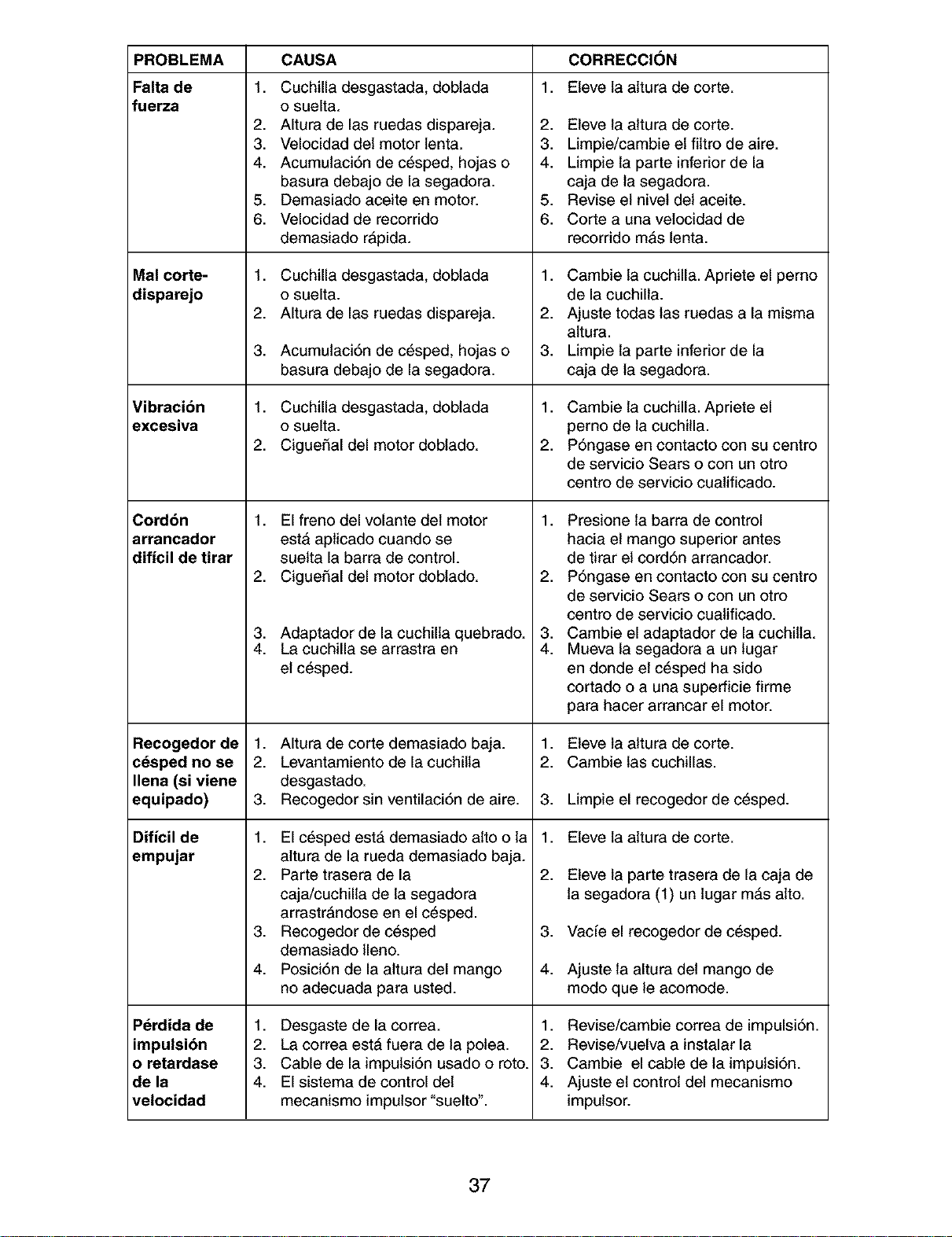
PROBLEMA
Falta de
fuerza
Mal corte-
disparejo
Vibracion
excesiva
Cordbn
arrancador
dificil de tirar
Recogedor de
cdsped no se
Ilena (si viene
equipado)
Dificil de
empujar
Pdrdida de
impulsion
o retardase
de la
velocidad
CAUSA
1. Cuchilla desgastada, doblada
o suelta.
2. Altura de las ruedas dispareja.
3. Velocidad del motor lenta.
4. Acumulaci6n de c_sped, hojas o
basura debajo de la segadora.
5. Demasiado aceite en motor.
6. Velocidad de recorrido
demasiado rApida.
1. Cuchilla desgastada, doblada
o suelta.
2. Altura de las ruedas dispareja.
3. Acumulaci6n de c_sped, hojas o
basura debajo de la segadora.
1. Cuchilla desgastada, doblada
o suelta.
2. CigueiSal del motor doblado.
1. El freno del volante del motor
est& aplicado cuando se
suelta la barra de control.
2. CigueiSal del motor doblado.
3. Adaptador de la cuchilla quebrado.
4. La cuchilla se arrastra en
el c_sped.
1. Altura de corte demasiado baja.
2. Levantamiento de la cuchilla
desgastado.
3. Recogedor sin ventilaci6n de aire.
1. El c_sped est#, demasiado alto o la
altura de la rueda demasiado baja.
2. Parte trasera de la
caja/cuchilla de la segadora
arrastrAndose en el c_sped.
3. Recogedor de c6sped
demasiado lleno.
4. Posici6n de la altura del mango
no adecuada para usted.
1. Desgaste de la correa.
2. La correa est& fuera de la polea.
3. Cable de la impulsi6n usado o roto.
4. El sistema de control del
mecanismo impulsor "suelto".
1,
CORRECCI()N
Eleve la attura de corte.
2. Eleve la altura de corte.
3. Limpie/cambie el filtro de aire.
4. Limpie la parte inferior de la
caja de la segadora.
5. Revise el nivel del aceite.
6. Corte a una velocidad de
recorrido mAs lenta.
1. Cambie la cuchilla. Apriete el perno
de la cuchilla.
2. Ajuste todas las ruedas a la misma
altura.
3. Limpie la parte inferior de la
caja de la segadora.
1. Cambie la cuchilla. Apriete el
perno de la cuchilla.
2. P6ngase en contacto con su centro
de servicio Sears o con un otro
centro de servicio cualificado.
1. Presione la barra de control
hacia el mango superior antes
de tirar el cord6n arrancador.
2. P6ngase en contacto con su centro
de servicio Sears o con un otro
centro de servicio cualificado.
3. Cambie el adaptador de la cuchilla.
4. Mueva la segadora a un lugar
en donde et c6sped ha sido
cortado o a una superficie firme
para hacer arrancar el motor.
1,
2.
3.
1.
2.
,
4.
Eleve ta altura de corte.
Cambie las cuchillas.
Limpie el recogedor de c_sped.
Eleve la attura de corte.
Eteve la parte trasera de la caja de
la segadora (1) un lugar m&s alto.
Vacfe el recogedor de c_sped.
Ajuste la altura del mango de
modo que le acomode.
1. Revise/cambie correa de impulsi6n.
2. Revise/vuelva a instalar la
3. Cambie el cable de la impulsi6n.
4. Ajuste el control del mecanismo
impulsor.
37
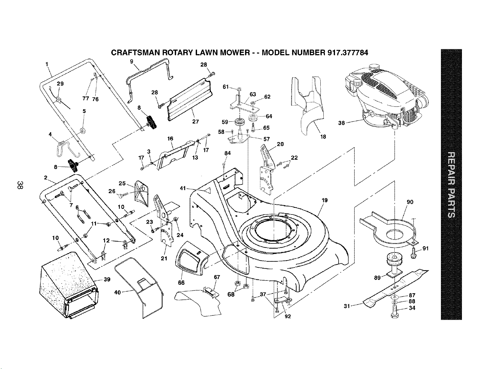
CRAFTSMAN ROTARY LAWN MOWER - - MODEL NUMBER 917.377784
9
\ 2e
61_
G3
CO
2
10
4
\
17
8
27
3E
18
90
67
66
68
92
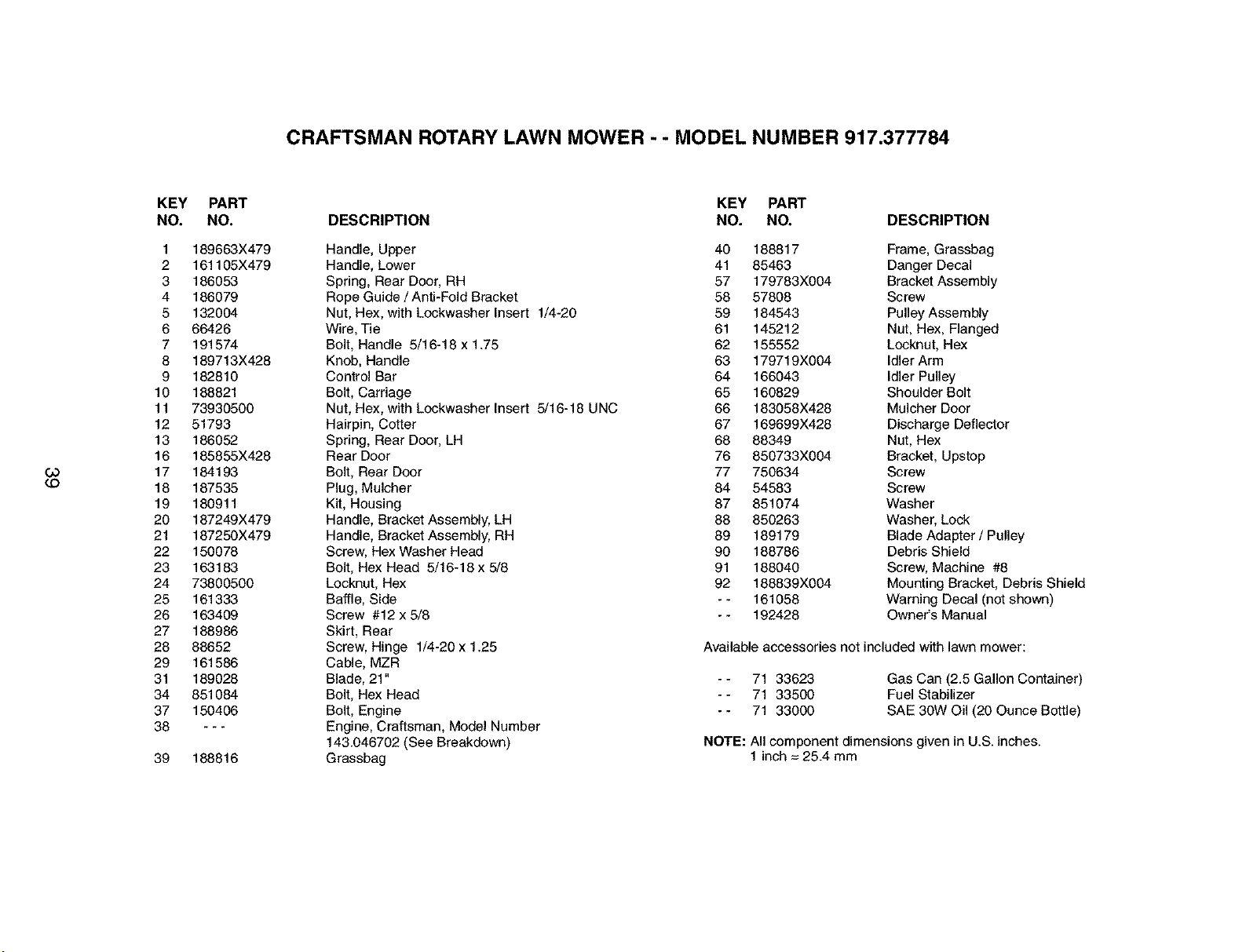
CRAFTSMAN ROTARY LAWN MOWER - - MODEL NUMBER 917.377784
CO
c.o
KEY PART
NO. NO.
1 189663X479
2 161105X479
3 186053
4 186079
5 132004
6 66426
7 191574
8 189713X428
9 182810
10 188821
11 73930500
12 51793
13 186052
16 185855X428
17 184193
18 187535
19 180911
20 187249X479
21 187250X479
22 150078
23 163183
24 73800500
25 161333
26 163409
27 188986
28 88652
29 161586
31 189028
34 851084
37 150406
38 ---
39 188816
KEY PART
DESCRIPTION NO. NO, DESCRIPTION
Handle, Upper 40 188817 Frame, Grassbag
Handle, Lower 41 85463 Danger Decal
Spring, Rear Door, RH 57 179783X004 Bracket Assembly
Rope Guide / Anti-Fold Bracket 58 57808 Screw
Nut, Hex, with Lookwasher Insert 1/4-20 59 184543 Pulley Assembly
Wire, Tie 61 145212 Nut, Hex, Flanged
Bolt, Handle 5/16-18 x 1.75 62 155552 Locknut, Hex
Knob, Handle 63 179719X004 Idler Arm
Control Bar 64 166043 Idler Pulley
Bolt, Carriage 65 160829 Shoulder Bolt
Nut, Hex, with Lookwasher Insert 5/16-18 UNC 66 183058X428 Mulcher Door
Hairpin, Cotter 67 169699X428 Discharge Deflector
Spring, Rear Door, LH 68 88349 Nut, Hex
Rear Door 76 850733X004 Bracket, Upstop
Bolt, Rear Door 77 750634 Screw
Plug, Mulcher 84 54583 Screw
Kit, Housing 87 851074 Washer
Handle, Bracket Assembly, LH 88 850263 Washer, Lock
Handle, Bracket Assembly, RH 89 189179 Blade Adapter / Pulley
Screw, Hex Washer Head 90 188786 Debris Shield
Bolt, Hex Head 5/16-18 x 5/8 91 188040 Screw, Machine #8
Locknut, Hex 92 188839X004 Mounting Bracket, Debris Shield
Baffle, Side - - 161058 Warning Decal (not shown)
Screw #12 x 5/8 - - 192428 Owner's Manual
Skirt, Rear
Screw, Hinge 1/4-20 x 1.25 Available accessories not included with lawn mower:
Cable, MZR
Blade, 21" - - 71 33623 Gas Can (2.5 Gallon Container)
Bolt, Hex Head - - 71 33500 Fuel Stabilizer
Bolt, Engine - - 71 33000 SAE 30W Oil (20 Ounce Bottle)
Engine, Craftsman, Model Number
143.046702 (See Breakdown) NOTE: All component dimensions given in U.S. inches.
Grassbag 1 inch = 25.4 mm
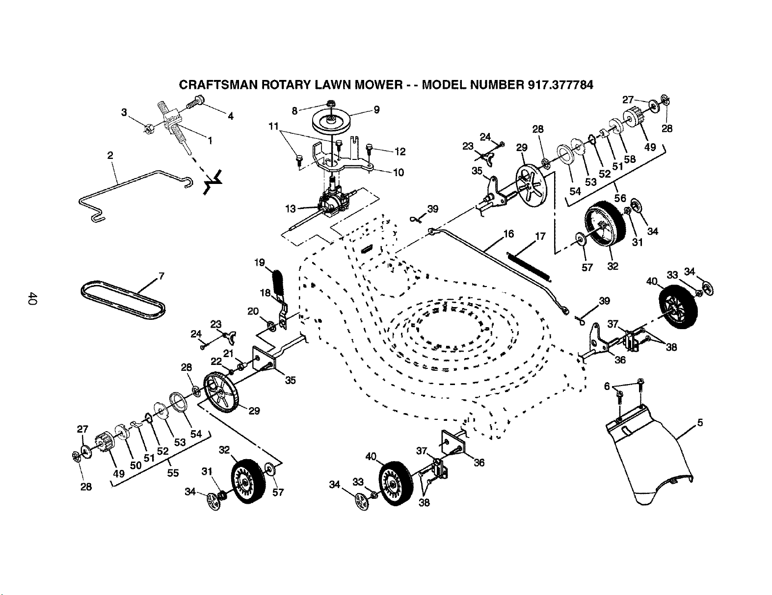
4:=
O
CRAFTSMAN ROTARY LAWN MOWER - - MODEL NUMBER 917.377784
2 _.
23
21
22
28
27
49
28
19
2O
54
53
55 31
34
38

CRAFTSMAN ROTARY LAWN MOWER - - MODEL NUMBER 917.377784
KEY PART
NO. NO.
1 189181
2 188952X428
3 751152
4 185681
5 161537X428
6 750634
7 182212
8 132010
9 189408
10 166021X004
11 17541011
12 54583
13 192425
16 161584
17 161602
18 188953X004
19 167650
20 12000022
21 163365
22 169911
23 161118X004
24 57808
27 52160
28 12000058
KEY PART
DESCRIPTION NO. NO. DESCRIPTION
Drive Control Assembly, Vari-Speed, with Cable 29 189403
Control Bar, Drive 31 145212
Nut, Hex 32 180762
Screw 33 83923
Cover Drive 34 77400
Screw, Threaded, Rolled #10-25 x .50 35 189180X004
V-Belt 36 160786X004
Nut, Flangelock 3/8-16 Zinc Plated 37 161463
Pulley, Drive 38 163409
Belt Keeper / Engine Bracket 39 700279
Screw 40 146249
Screw 49 175103
Gearcase Assembly (See Breakdown) 50 175102
Rod, Connecting 51 175098
Spring, Extension 52 188291
Spring, Selector 53 175104
Knob, Selector Spring 54 184172
E-Ring 7/8 55 188330
Bearing Support 56 188331
Bearing, Ball 57 67725
Retainer, Drive Assembly, Stamped 58 175105
Screw, Hex Head, Tapping 1/4-20 x .75
Washer, Shim (as required)
E-Ring 7/16
Cover, Dust, Wheel
Nut, Hex, Flanged
Wheel 9 x 2
Nut, Hex, Flangelock 3/8-16
Hubcap, Mag, Platinum
Shaft Assembly, Rear
Shaft Assembly, Front
Retainer, Front Shaft
Screw #12 x 5/8
Clip, Retainer
Wheel 8 x 2
Pinion, Gear
Retainer, Drive, RH
Pawl
Spring, Torsion
Disc, Drive
Seal, Friction
Pinion/Pawl Assembly, RH
Pinion/Pawl Assembly, LH
Washer, Flat 1/2
Retainer, Drive, LH
NOTE: All component dimensions given in U.S. inches.
1 inch = 25.4 mm
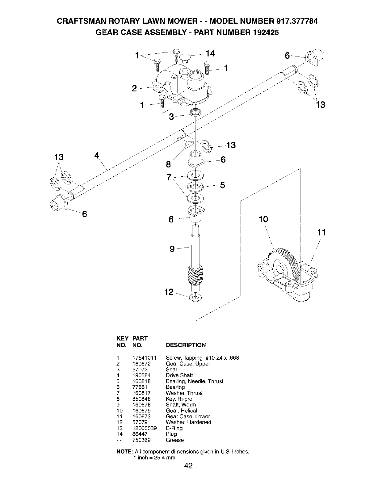
CRAFTSMAN ROTARY LAWN MOWER - - MODEL NUMBER 917.377784
GEAR CASE ASSEMBLY - PART NUMBER 192425
13
13
\
\
\
6
12_
J
10
11
KEY PART
NO. NO. DESCRIPTION
1 17541011 Screw, Tapping #10-24 x .668
2 160672 Gear Case, Upper
3 57072 Seal
4 190584 Drive Shaft
5 160818 Bearing, Needle, Thrust
6 77881 Bearing
7 160817 Washer, Thrust
8 850848 Key, Hi-pro
9 160678 Shaft, Worm
10 160679 Gear, Helical
11 160673 Gear Case, Lower
12 57079 Washer, Hardened
13 12000039 E-Ring
14 86447 Plug
- - 750369 Grease
NOTE: All component dimensions given in U.S. inches.
1 inch = 25.4 mm
42
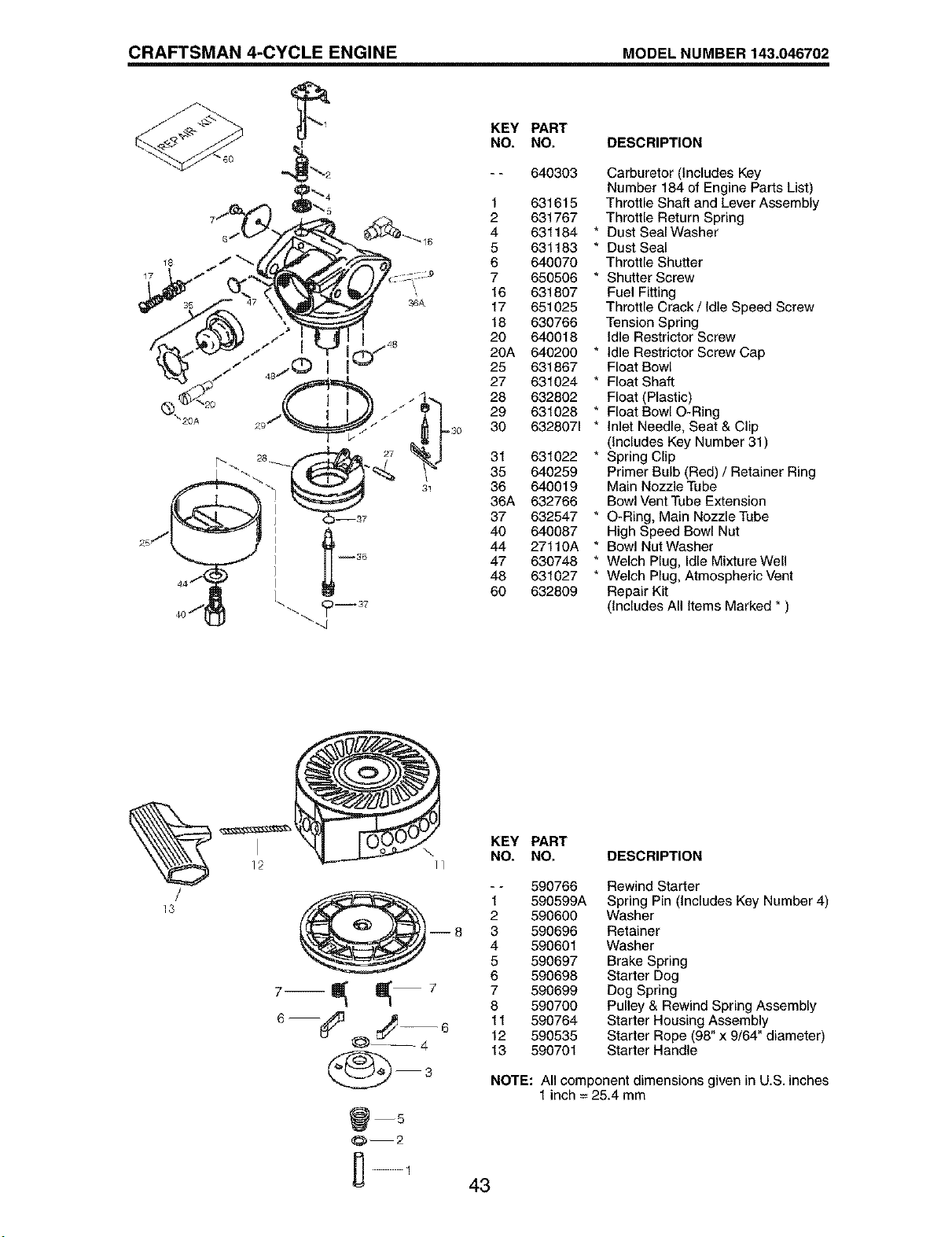
CRAFTSMAN 4-CYCLE ENGINE MODEL NUMBER 143.046702
KEY
NO.
1
2
4
5
6
7
16
17
18
20
20A
25
27
28
29
-3o 30
PART
NO.
640303
631615
631767
631184
631183
640070
650506
631807
651025
630766
640018
640200
631867
631024
632802
631028
6328071
31 631022
35 640259
36 640019
36A 632766
37 632547
40 640087
44 27110A
47 630748
48 631027
60 632809
DESCRIPTION
Carburetor (Includes Key
Number 184 of Engine Parts List)
Throttle Shaft and Lever Assembly
Throttle Return Spring
* Dust Seal Washer
* Dust Seal
Throttle Shutter
* Shutter Screw
Fuel Fitting
Throttle Crack / Idle Speed Screw
Tension Spring
Idle Restrictor Screw
* Idle Restrictor Screw Cap
Float Bowl
* Float Shaft
Float (Plastic)
* Float Bowl O-Ring
* Inlet Needle, Seat & Clip
(Includes Key Number 31)
* Spring Clip
Primer Bulb (Red) / Retainer Ring
Main Nozzle Tube
Bowl Vent Tube Extension
* O-Ring, Main Nozzle Tube
High Speed Bowl Nut
* Bowl Nut Washer
* Welch Plug, Idle Mixture Well
* Welch Plug, Atmospheric Vent
Repair Kit
(Includes All Items Marked * )
/
13
KEY PART
NO. NO. DESCRIPTION
-- 590766
1 590599A
2 590600
--8 3 590696
4 590601
5 590697
6 590698
7--_--7 7590699
8 590700
6 --_3 ,_- 6 11 590764
@ 12 590535
13 590701
0--2
Rewind Starter
Spring Pin Includes Key Number 4)
Washer
Retainer
Washer
Brake Spnng
Starter Dog
Dog Spring
Pulley & Rewind Spring Assembly
Starter Housing Assembly
Starter Rope (98" x 9/64" diameter)
Starter Handle
NOTE: All component dimensions given in U.S. inches
1inch = 25.4 mm
43
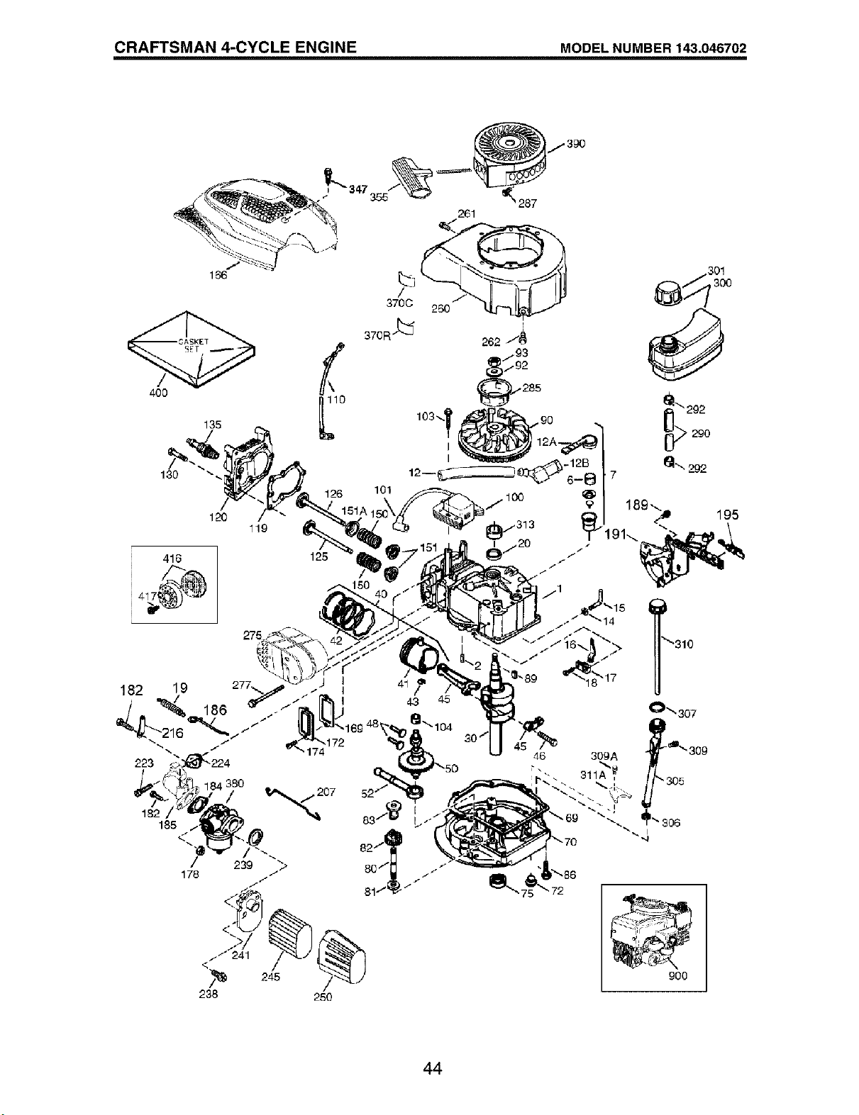
CRAFTSMAN 4-CYCLE ENGINE MODEL NUMBER 143.046702
/390
130
126
120
119
125
101
<
/_ 245
238 250
301
• 306
900
44
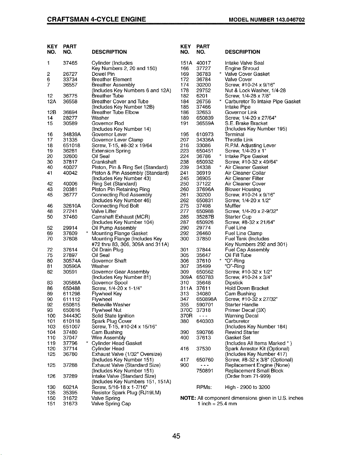
CRAFTSMAN 4-CYCLE ENGINE MODEL NUMBER 143.046702
KEY PART KEY PART
NO. NO. DESCRIPTION NO. NO. DESCRIPTION
2
6
7
37465
26727
33734
36557
12 36775
12A 36558
12B 36694
14 28277
15 30589
16 34839A
17 31335
18 651018
19 36281
20 3260O
30 37817
40 40027
41 40042
42 40006
43 20381
45 36777
46 32610A
48 27241
50 37460
52 29914
69 37609
70 37608
72 37614
75 27897
80 30574A
81 30590A
82 30591
83 30588A
86 650488
89 611298
90 611112
92 650815
93 650816
100 34443C
101 610118
103 651007
104 37480
110 37047
119 37796
120 37714
125 36780
125 37288
126 37289
130 6021A
135 35395
150 31672
151 31673
Cylinder(Includes 151A 40017
Key Numbers 2, 20 and 150) 166 37727
Dowel Pin 169 36783 *
Breather Element 172 36784
Breather Assembly 174 30200
(Includes Key Numbers 6 and 12A) 178 29752
Breather Tube 182 6201
Breather Cover and Tube 184 26756 *
(Includes Key Number 12B) 185 37466
Breather Tube Elbow 186 32653
Washer 189 650839
Governor Rod 191 36559A
(Includes Key Number 14)
Governor Lever 195 610973
Governor Lever Clamp 207 34336A
Screw, T-15, #8-32 x 19/64 216 33086
Extension Spring 223 650451
Oil Seal 224 36786 *
Crankshaft 238 650932
Piston, Pin & Ring Set (Standard) 239 34338 *
Piston & Pin Assembly (Standard) 241 36919
(Includes Key Number 43) 245 36905
Ring Set (Standard) 250 37122
Piston Pin Retaining Ring 260 37696A
Connecting Red Assembly 261 30200
(Includes Key Number 46) 262 650831
Connecting Rod Bolt 275 37498
Valve Lifter 277 650988
Camshaft Exhaust (MCR) 285 35287B
(Includes Key Number 104) 287 650926
Oil Pump Assembly 290 29774
Mounting Flange Gasket 292 26460
Mounting Flange (Includes Key 300 37850
#72 thru 83, 306, 309A and 311A)
Oil Drain Plug 301 37844
Oil Seal 305 35647
Governor Shaft 306 37610 *
Washer 307 35499
Governor Gear Assembly 309 650562
(Includes Key Number 81) 309A 650783
Governor Spool 310 35648
Screw, 1/4-20 x 1-1/4" 311A 37611
Flywheel Key 313 34080
Flywheel 347 650898A
Belleville Washer 355 590701
Flywheel Nut 370C 37318
Solid State Ignition 370R - - -
Spark Plug Cover 380 640303
Screw, T-15, #10-24 x 15/16"
Cam Bushing 390 590766
Wire Assembly 400 37613
Cylinder Head Gasket
Cylinder Head 416 37530
Exhaust Valve (1/32" Oversize)
(Includes Key Number 151) 417 650760
Exhaust Valve (Standard Size) 900 - - -
(Includes Key Number 151) 750891
Intake Valve (Standard Size)
(Includes Key Numbers 151,151A)
Screw, 5/16-18 x 1-7/16"
Resistor Spark Plug (RJ19LM)
Valve Spring
Valve Spring Cap
Intake Valve Seal
Engine Shroud
Valve Cover Gasket
Valve Cover
Screw, #10-24 x 9/16"
Nut & Lock Washer, 1/4-28
Screw, 1/4-28 x 7/8"
Carburetor To Intake Pipe Gasket
Intake Pipe
Governor Link
Screw, 1/4-20 x 27/64"
S.E. Brake Bracket
(Includes Key Number 195)
Terminal
Throttle Link
R.P.M. Adjusting Lever
Screw, 1/4-20 x 1"
Intake Pipe Gasket
Screw, #10-32 x 49/64"
Air Cleaner Gasket
Air Cleaner Collar
Air Cleaner Filter
Air Cleaner Cover
Blower Housing
Screw, #10-24 x 9/16"
Screw, 1/4-20 x 1/2"
Muffler
Screw, 1/4-20 x 2-9/32"
Starter Cup
Screw, #8-32 x 21/64"
Fuel Line
Fuel Line Clamp
Fuel Tank (Includes
Key Numbers 292 and 301)
Fuel Cap Assembly
Oil Fill Tube
"O"-Ring
"O"-Ring
Screw, #10-32 x 1/2"
Screw, #10-24 x 3/4"
Dipstick
Hold Down Bracket
Cam Bushing
Screw, #10-32 x 27/32"
Starter Handle
Primer Decal (3X)
Warning Decal
Carburetor
(Includes Key Number 184)
Rewind Starter
Gasket Set
(Includes All Items Marked * )
Spark Arrestor Kit (Optional)
(Includes Key Number 417)
Screw, #8-32 x 3/8" (Optional)
Replacement Engine (None)
Replacement Small Block
(Order from 71-999)
RPMs: High - 2900 to 3200
NOTE: All component dimensions given in U.S. inches
1 inch = 25.4 mm
45

SERVICE NOTES
46

SERVICE NOTES
47

Your Home
For repair - in your home - of all major brand appliances,
lawn and garden equipment, or heating and cooling systems,
no matter who made it, no matter who sold it!
For the replacement parts, accessories and
owner's manuals that you need to do-it-yourself.
For Sears professional installation of home appliances
and items like garage door openers and water heaters.
1-800-4-MY-HOME _ Anytime, day or night
(1-800-469-4663) (U.S.A. and Canada)
www.sears.com www.sears.ca
Our Home
For repair of carry-in products like vacuums, lawn equipment,
and electronics, call or go on-line for the nearest
Sears Parts and Repair Center.
1-800-488-1222 Anytime, day or night (U.S.A. only)
www,seats.com
To purchase a protection agreement (U.S.A.)
or maintenance agreement (Canada) on a product serviced by Sears:
1-800-827-6655 (u.s.,% 1-800-361-6665 (Canada)
Para pedir servicio de reparaciSn
a domicilio, y para ordenar piezas:
1-888-SU-HOGAR sM
Au Canada pour service en fran_2,ais:
1-800-LE-FOYER Mc
(1-800-533-6937)
www.sears.ca
SEAR6
© Sea_, RoebuckandCo.
® Registered Trademark / TMTrademark / SMService Mark of Sears, Roebuck and Co.
® Marca Registrada / TMMarca de FAbrica / SMMarca de Servicio de Sears, Roebuck and Co.
MCMarque de commerce / MDMarque d_pos_e de Sears, Roebuck and Co.
192428 04.07.04 BY Printed in U.S.A.