User Manual Rinnai INF26EN60A Gas Continuous Flow Water Heater
WATER TEMPERATURE CONTROL
MAXIMUM DELIVERY TEMPERATURES
Rinnai gas continuous flow water heaters are factory pre-set to various maximum delivery temperatures depending on model and their intended application. For the majority of applications, the factory pre-set temperature is appropriate. In the unlikely event this is not the case this setting can be increased or decreased by an authorised person such as a licensed plumber.
NOTE:
This does not apply to “50 degree compliant” models. To meet the regulatory requirements the maximum delivery temperature is factory set and sealed.
For model specific information in regards to the factory pre-set temperature of your appliance refer to "Table 3. Maximum Delivery Temperatures" on page 34. The appliance model number can be found on the dataplate, which is located on the left hand side of appliance.
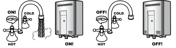
OPERATION WITHOUT WATER CONTROLLERS
Rinnai gas continuous flow water heater products do not use a pilot light. When installed and operated without water controllers, the opening of any hot water tap will automatically start the appliance. Once water is flowing through the appliance the burner will be ignited by electronic ignition and water will be delivered at the maximum temperature that the unit is capable of delivering. As with conventional water heaters cold water will need to added to reduce the temperature to the desired level. When the hot water tap is closed and water ceases to flow through the appliance, the burner flame will be extinguished.
Rinnai WATER CONTROLLERS
NOTE
Other manufacturers water controllers are NOT compatible with Rinnai water heaters. Rinnai water controllers brought in from other countries are also NOT compatible with Rinnai appliances sold in Australia. Water controllers MUST NOT be used with any Solar Boost water heater.
Water controllers are available as an optional extra. Wireless, Universal and Deluxe water controllers can be used together and will function as described in the Operation Sections of this manual. Refer to "Water Controller Configurations" on page 9 to confirm the maximum number and combination of water controllers that can be fitted to your water heater model.
Location
Water controllers must be installed in shaded and clean locations. They should be fitted out of reach of children suggested height from floor to be at least 1500 mm).
Water Resistance
The MC-601Q universal water controller is a water resistant device, however excessive exposure to water such as immersion may result in damage to the water controller. Durability of water controllers is improved when positioned outside of the shower recess.
NOTE
Controllers MUST BE installed at least 400 mm above the highest part of a sink, basin or bath. DO NOT immerse the water controller into water. AVOID direct exposure to water or steam as these conditions may cause a malfunction. ALWAYS AVOID exposure to water when the battery compartment is open. When cleaning your water controller use ONLY a damp cloth and a mild detergent.
Temperature Control
Water controllers allow precise temperature control by the user. When used correctly, the hot water unit will deliver the selected temperature, even when the water flow is varied, or more than one tap is in use.
Only one MC model water controller can be designated as a ‘Master’ water controller and this is normally used in the kitchen. All the remaining water controllers are designated as ‘Sub’ water controllers and are for use in bathrooms, toilets and laundries. The maximum temperature limit for all ‘Sub’ water controllers is restricted to 50°C to minimise the risk of burns in these areas.
Any water controller that currently has priority is capable of setting the water temperature to be delivered, however the water heater can only assign 'priority' to one controller at a time and deliver the one set temperature. The available temperatures (°C) are as follows:

Note
Whilst hot water outlets are open ONLY the control used to set to delivery may be used to further adjust it. Transfer of 'priority' between controllers is NOT possible until all hot water taps have been closed. These are safety features.
For hygiene in sanitary areas such as bathrooms, the suggested temperature should be 37°C ~ 43°C.
The above is a suggestion only, as you may find higher or lower temperatures more comfortable, however maintaining lower temperatures also helps to save energy.
To obtain water temperatures lower than 37°C, simply open the cold water tap and add cold water until the desired lower temperature is reached.
NOTE
The temperature of outgoing hot water is constantly monitored by a built-in sensor. If the temperature of the outgoing hot water rises to more than 3°C above the selected temperature shown on the digital monitor or the pre-set limit when water controllers are not fitted, the burner will automatically go out. The ‘in use’ indicator will also go out. The burner will ignite again once the outgoing hot water temperature falls to that shown on the digital monitor (or the pre-set limit of the appliance)
** Temperature may not be available on all installations. Some Rinnai gas continuous flow water heaters can be programmed to deliver higher temperatures from the master water controller, or may be programmed to restrict the maximum available delivery temperature. Contact Rinnai for more details.
***Temperature limiting devices (where fitted) may further control what maximum delivery temperature is available to outlets.
Water Controller Configurations
Deluxe kitchen, bathroom and wireless water controllers are also available and various combinations of universal and the deluxe and wireless water controllers can be used with the following limitations:
- A maximum of FOUR water controllers can be fitted.
- Only ONE master controller can be installed. This can be a deluxe kitchen (MC-100V), or any other MC model water controller (when programmed to be a 'Master' controller).
IMPORTANT
When a deluxe kitchen (MC-100V) water controller is fitted it will always function as a 'Master' controller, this is the default setting and can NOT be changed.
- A up to a maximum of TWO BC-100V water controllers can be installed.
- The FOURTH water controller in any installation MUST BE a MC-601Q or a MC-503RC-S.
UNIVERSAL WATER CONTROLLER (MC-601Q) OPERATION
Turning On
If the water controller is switched off (No digits displayed in the digital monitor window) press the On/Off button once. The ON indicator will illuminate, indicating that the hot water unit will be ready to supply hot water once a hot water tap is opened.
Adjusting Temperature
Select the desired temperature using the Hot water temp or buttons until the required temperature is displayed on the digital monitor.
To operate the hot water unit, open any hot water tap. This will automatically light the burner providing hot water. The water heater ‘In Use’ indicator will illuminate on the water controller(s).
Once the hot water is running, if the set temperature is either too hot or cold press the Hot water temp or buttons until the desired temperature is reached.
Transferring Priority
To control the water delivery temperatures when using two or more water controllers it is necessary to have priority transferred to the water controller you wish to use. Transferring of priority will NOT be possible if the ‘In Use’ indicator is currently illuminated, as this indicates hot water is flowing and that another water controller already has priority.
An illuminated Priority indicator confirms that the desired water controller is in control of the water delivery temperature. If the Priority indicator is not illuminated press the Priority Transfer button once. The Priority indicator will illuminate, indicating that hot water temperature control has been transferred and that the hot water unit will be ready to supply hot water once a hot water tap is opened.
Water Controller Combinations & Configurations
Wireless, Universal and Deluxe water controllers can be combined, Refer to "Water Controller Configurations" on page 9 to confirm the maximum number and combination of controllers that can be fitted.
SMARTSTART PRE-HEAT SYSTEM
The “Preheat” function works in conjunction with various Rinnai water heater models when the separately installed and optional Rinnai “Smartstart®” module is installed.
Preheat Function
When the "Preheat" function is activated and used in accordance with these instructions, water in the pipework connected between the water heater and the hot water outlets in your house is warmed before any outlets are opened. This results in water savings and added convenience.
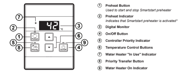
Preheat Operation
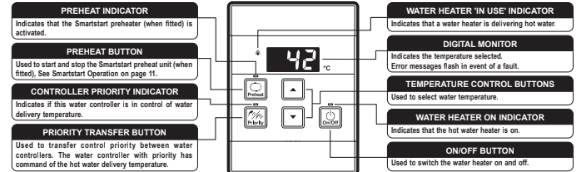
- Ensure that the hot water unit is on (temperature digits are displayed in the digital monitor 3 ). If more than one water controller is fitted press the "Priority Transfer" button 8 to pass on priority to your desired water controller. The "Controller Priority" indicator 5 will illuminate to confirm that priority has been assigned to this water controller and that the hot water unit is ready to deliver hot water.
- Select the desired temperature using the "Temperature Control" buttons 6 until the required temperature is displayed in the digital monitor 3 .
- Press the "Preheat" button 1 once. The "Preheat" indicator 2 and the "In Use" indicator 7 will illuminate, signifying that the preheat system has been activated.
- Wait for the "In Use" indicator 7 to go out (this may take 2 to 5 minutes). When this happens it signifies that the water in the pipework has now been pre-warmed and is ready for delivery, and that a hot water tap can now be opened.
NOTE
The waiting time may be longer or shorter depending on your particular installation configuration.
For best results always wait for the "In Use" indicator 7 to go out before opening a hot water tap.
The preheat function is cancelled 5 minutes after activation and the "Preheat" indicator 2 will go out. This is to conserve energy. To reactivate, simply repeat steps 2-4 above.
If the "Preheat" button 1 is pressed and the 'Smartstart' preheat unit is not installed, the "Preheat" indicator 2 will still light however there will be no preheat function. The "Preheat" indicator 2 will go out after a short time and will not affect the other functions of the water controller or water heater.
When deluxe Bathroom water controllers are fitted, after using the Shower Saver / Bath Fill function wait 30 seconds before activating the 'Preheat' function. Attempting to use the 'Preheat' function earlier will result in voice prompts being repeated until the system is reset. The system can be reset by pressing the "On /Off" button twice.
Water Controller Functions
Water controller functions such as temperature control and transfer of priority between multiple controllers are not affected by the operation of the preheat. Such functions are described in the applicable sections of this manual.
TROUBLE SHOOTING
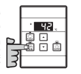
No power display Wireless Water Controller (when fitted)
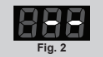
When power to the water heater is disconnected the LCD of all wireless water controllers will display as shown to the right.
Check that the power is available, and that the water heater is plugged in with the power point turned ‘on’.
Troubleshooting Without Water Controllers
If you have no water controllers and experience the following symptoms, carry out these suggestions. If the symptom continues, contact Rinnai for advice.
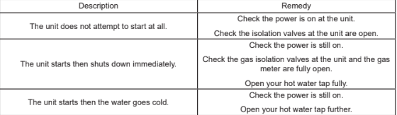
Faults caused by insufficient gas supply, insufficient water supply, gas quality, water quality, installation errors or operation errors are NOT covered by the Rinnai warranty. Refer to separate warranty booklet for details.
SERVICE
Wired and wireless water controllers, transceivers and water heaters do not contain user serviceable parts and must only be serviced and repaired by an authorised person.
Rinnai has a Service and Spare Parts network with personnel who are fully trained and equipped to give the best service on your Rinnai appliance. If your appliance requires service, please call our National Help Line or the Hot Water Service Line (contact numbers for which are on the back cover of this manual).
NOTE
When making a service enquiry, having both the model and serial numbers available, will help our staff quickly identify your appliance and better attend to your needs.
This information should have been copied to the "Installation Record" on page 31 by your installer, however if this is not the case, the information can also be found on the data plate located on the left hand side of the appliance.
Rinnai recommends that this appliance be serviced every 3 years.
HOT WATER DELIVERY TEMPERATURE
Local regulations and or the requirements of AS/NZS 3500 MUST BE addressed regarding the temperature limitations of hot water supplied to areas used primarily for personal hygiene. The temperature of water to these areas may be limited to 50°C or less.
To ensure these regulations and or requirements are met the system MUST BE installed in accordance with the Installation Configurations" below.
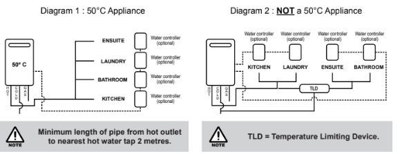
Installation Configurations
If the appliance is marked to state that it delivers water not exceeding 50°C, local regulations may permit installation without a Temperature Limiting Device. Installations without a Temperature Limiting Device are shown in Diagram below. If you are unsure about your local regulations contact your regulating authority or Rinnai.
If the appliance is NOT marked to state that it delivers water not exceeding 50°C, or your local regulations require installation with a Temperature Limiting Device then install the appliance in accordance with Diagram 2 below.
IMPORTANT
If the appliance is to deliver water primarily for the purposes of personal hygiene in an early childhood centre, primary or secondary school, nursing home or a similar facility for the care of young, aged, sick or disabled persons as defined in AS/NZ 3500 a Temperature Limiting Device (TLD), such as a Tempering Valve may be required even if the appliance is set to 50o C or less. For these types of applications contact Rinnai.
Universal water controllers are available as an optional extra and will function as described in the Operation Section of this manual. Refer to "Water Controllers Limitations" on page 25 to confirm the maximum number and combination of water controllers that can be fitted.
For detailed installation information of Universal water controllers refer to the "Water Controller Installation" chapter of this manual starting on page 25.
FLUEING
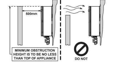
Horizontal Obstructions
AS/NZS 5601 ‘Gas Installations’ stipulates a minimum horizontal clearance of 500 mm between a building structure and obstruction facing the terminal.
For correct operation of Rinnai external gas continuous flow water heaters such a building structure MUST ‘obstruct’ the full front cover height of the appliance (for appliance dimensions, refer to "Table 1. Appliance Dimensions" on page 32), extend vertically above and below the front cover as shown below.
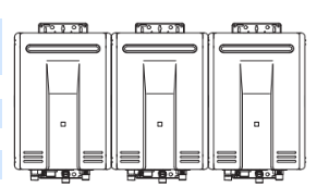
Multiple Appliance Installations
In reference to Horizontal Terminal Clearances (Extract from AS/NZS 5601) dimension ‘h’ on page 21 does not apply when multiple Rinnai external water heaters of the same model are installed on the same vertical face with flue terminals at the same height.
Under these conditions appliances can abut each other as shown left. Consider the total gas consumption of all appliances applies when determining other clearances.
For appliance dimensions, refer to "Table 1. Appliance Dimensions" on page 32 and "Diagram 1. Dimensions" on page 33.
WATER CONTROLLER INSTALLATION
Master / Sub Water Controllers & Associated Temperatures
Only one MC model water controller can be designated as the 'Master' water controller. This water controller is normally used in the kitchen and usually has a maximum temperature of 55°C, which is sufficient for almost all kitchen applications. Temperatures higher than 55°C are possible but usually unnecessary and will result in higher gas use and increase the risk of burns.
Some additional conditions regarding Master Controller maximum temperatures apply when a wireless water controller is used as the 'Master' water controller.
i) Temperatures of 55°C or higher can only be selected on the controller designated as the 'Master' water controller if the transceiver 'Max Temp' is also programmed to 55°C or higher.
ii) The temperature of hot water delivered is always limited to the maximum temperature programmed into the water heater itself. For example, if the transceiver maximum temperature is programmed to 55°C and the water heater is limited to 50°C, the maximum temperature that the water heater will deliver is 50°C. In this case 55°C will be displayed on the wireless Master Controller until a tap is opened after which the display will revert to 50°C.
IMPORTANT
The water heater maximum temperature cannot be adjusted by the user. These adjustments can ONLY be carried out by a qualified and licensed trades person.
The remaining water controllers are designated 'sub' controllers and are for use in bathrooms, toilets and laundries. The temperature limit for all 'Sub' controllers is always 50°C to minimise the risk of burns in these areas. Adhesive labels are included for individual identification of wireless water controllers as master (Kitchen) or sub (Bathroom) water controllers. These labels are usually placed on the top back of the wireless water controller body.
Water Controllers Limitations
A maximum of FOUR universal MC-601Q water controllers in total can be fitted.
Deluxe kitchen, bathroom and wireless water controllers are also available and various combinations of universal and the deluxe and wireless water controllers can be used with the following limitations:
- A maximum of FOUR water controllers can be fitted.
- Only ONE master controller can be installed. This can be a deluxe kitchen (MC-100V), or any other MC model water controller (when programmed to be a 'Master' controller).
IMPORTANT
When a deluxe kitchen (MC-100V) water controller is fitted it will always function as a 'Master' controller, this is the default setting and can NOT be changed.
When fitted the 'Master' controller configuration of a MC-100V water controller overrides all other pre‐existing wired or wireless 'Master' controller configurations.
- Up to TWO deluxe bathroom water controllers can be installed.
- The FOURTH water controller in any installation MUST BE a wireless or a universal water controller.
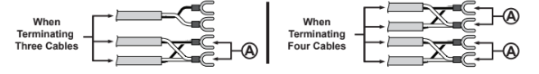
Joining Communication Cables (REU-A / REU-AM)
The water heater end of the cables are fitted with spade terminals. Only two pairs of cables (4 spade connectors in total) may be terminated. When attaching three or four cables it is necessary to join the cable terminals as follows:
For each pair cut off the existing spade connectors and re-terminate each pair into a new spade connector A so that there are only two sets of spade connectors (4 spade connectors in total) to be terminated (spade connectors are available from your local electrical component retailer).
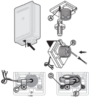
Connecting Communication Cable(s) With 'Ezi connect' (REU-A / REU-AM)
- Isolate the electric power supply by switching the power point off and removing the power plug of the water heater from the electric power socket.
- Remove the retaining screw A of the 'Ezi connect' cable connector at the base of the appliance.
- Swing the 'Ezi connect' cable connector door open and thread the cable through the weather seal of the cable access hole B in the direction shown allowing sufficient cable length so that the sheath of the cable can be secured with cable clamp C .
- Loosen screw terminals D & E and connect the cable spade connectors to these terminals and re-tighten. Polarity is not important, either wire colour can be connected to either terminal.
- Return the 'Ezi connect' cable connector to the original position taking care not to damage cable wires in the process and replace the retaining screw A .
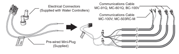
Connecting Communication Cables to Mini-Plug (REU-E)
CAUTION
Installation MUST be completed by a qualified and licensed trades person. DO NOT attempt to connect water controller cables to the mini-plug when it is plugged into the PCB unless the electric power to the water heater is switched ‘off’ otherwise damage to electrical components may occur.
Water controllers are connected to the PCB via a dedicated pre-wired mini-plug (supplied).
Use the supplied electrical cable connectors to terminate the water controller wires to those of the mini-plug. The existing spade connectors of the communication cables will need to be removed prior to termination. Controllers are not polarity sensitive, however to avoid confusion it is recommended that like coloured wires be terminated together.
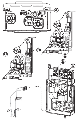
Connecting Communication Cables to PCB (REU-E)
- Isolate the electric power supply by switching the power point off and removing the power plug of the water heater from the electric power socket.
- Remove the front cover of the appliance.
- Insert the mini-plug and the connected water controller cables through the cable access A at the base of the appliance. Ensuring that the cable connectors are located inside the appliance for protection.
- Locate the PCB B , (bottom right of appliance), and carefully rotate the plastic safety cover C out of the way.
- Locate the accessory port socket D bottom front of the PCB).
- Plug the mini-plug into the accessory port socket D (the plug and socket are keyed so that they can only be plugged in the one direction).
- Proceed with the water controller installation and connect the communication cables to controllers.
UNIVERSAL WATER CONTROLLER (MC-601Q) INSTALLATION
1. Determine the most suitable position, refer "Location" on page 26.
2. Mark and drill 3 holes (mounting and cable access) refer to "Table 1. Appliance Dimensions" on page 32 and "Diagram 1. Dimensions" on page 33 for water controller dimensions.
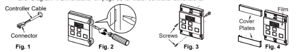
3. When running cable through the access hole ensure the connector end of the cable is located nearest to the water controller (Fig. 1).
4. Carefully remove the cover plates from the water controller, using a screw driver (Fig. 2).
5. Connect the cable to the water controller. Feed any excess cable lengths into the wall cavity to avoid the pinching of cables between the wall and the water controller.
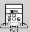
6. Fix the water controller to the wall using the appropriate fixings (Fig. 3).
7. Remove protective film from the water controller face and replace the cover plates (Fig. 4).
Additional Programming & Activation Requirements
QUESTION
1. Are there four water controllers connected?
IF NO: You have three (or fewer) water controllers, go to Question 2.
IF YES: You will need to activate the fourth water controller as follows:
STEP 1: For the water controller in the KITCHEN ONLY, press and hold the ‘Priority Transfer’ and ‘On/Off’ buttons simultaneously (see Fig. 1) until a ‘beep’ is heard approximately 5 seconds).
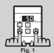
STEP 2: Check that the display on ALL FOUR water controllers is lit and displaying a temperature when ‘switched on’. If any ONE of the water controller displays two dashes (see Fig. 2) repeat STEP 1.
This completes the activation procedure for the fourth water controller, you may ignore Question 2.
2. Is the water heater marked to state it delivers water not exceeding 50°C?
IF YES: No further action required..
IF NO: You will need to program the kitchen water controller to enable selection of temperatures higher than 50°C.
STEP 1: For the water controller in the KITCHEN ONLY, press and hold the ‘Priority Transfer’ and ‘On/Off’ buttons simultaneously (Fig. 3) until a ‘beep’ is heard approximately 5 seconds).
STEP 2: When the water controller fitted in the KITCHEN is switched On, it should be possible to select temperatures higher than 50°C. If not, repeat STEP 1.
NOTE
If the water controller in the kitchen is replaced, repeat STEP 1 for the replacement water controller. If the water controller in the kitchen is swapped with another water controller (for example, the water controller fitted in a bathroom), repeat STEP 1 for the water controller moved from the kitchen to the bathroom. Then perform STEP 1 for the water controller moved from bathroom to the kitchen.
COMMISSIONING
TESTING
1. Before final connection of the water heater purge gas, hot water and cold water supply lines. Debris or swarf in either the gas or water supplies may cause damage.
2. Turn on gas and cold water supplies.
3. Test for water leaks and gas escapes near the unit.
4. Isolate gas supply. Remove test point screw located on the gas inlet connection and attach pressure gauge.
IMPORTANT
Confirm the control board dipswitch settings are set to the correct positions as required , i.e. factory default or with a Sideways Flue Diverter fitted, see "Sideways Flue Diverter" on page 22 for details.
5. Turn the power 'on' at the power point socket and turn on gas.
6. If water controllers are fitted, ensure they are 'ON', with the maximum delivery temperature selected and open ALL available hot water outlets.
If water controllers are not fitted, simply open ALL available hot water outlets.
CAUTION
Ensure building occupants DO NOT have access to hot water outlets during this procedure.
7. Operate ALL other gas appliances at their maximum gas rate, in accordance with manufacturers instructions.
8. With all gas appliances in operation at maximum gas rate, the pressure should read between 1.13 - 3.0 kPa on Natural Gas. On LPG the pressure should be 2.75 - 3.0 kPa. If the pressure is lower, the gas supply is inadequate and the appliance will not operate to specification. It is the Installers responsibility to check the gas meter, service regulator and pipe work for correct operation/sizing and rectify as required.
NOTE
The gas regulator on the appliance is electronically controlled and factory pre-set. Under normal circumstances it DOES NOT need adjustment during installation.
9. Close hot water taps including the shower.
10. Inspect and clean the strainer located on the cold water inlet connection. This procedure may need to be repeated to ensure the strainer remains clear, especially on new installations.
11. If water controllers are fitted, it is necessary to test their operation through the complete range of functions refer to the Operation sections of this manual).
12. Confirm the hot water delivery temperature(s) using a thermometer. If controllers are fitted, ensure temperatures exceeding 50°C cannot be selected on bathroom or ensuite controllers. Refer to the section Delivery Temperature’ below for more details.
13. After testing is completed, explain to the householder the functions and operation of the water heater and water controllers (if fitted). Ensure the "Installation Record" on page 31 is filled in and that this booklet is handed to the customer. Reminding the customer to complete the Warranty Card and forward to Rinnai.
DELIVERY TEMPERATURE
50°C Compliant Models
50°C Compliant" appliances are factory set to deliver a maximum temperature not exceeding 50°C. For fine tuning they have an incremental adjustment mechanism that allows the installer to increase the appliance delivery temperature incrementally from the 'Factory Set’ value to temperatures slightly exceeding 50°C. This is intended to enable compensation for temperature losses in the pipe-work between the water heater and any outlets and achieve the required temperature at the outlet. Instructions for incremental temperature adjustment are located in the instruction pocket inside the appliance front cover.
For All Other Models
Rinnai gas continuous flow water heaters are factory pre-set to various maximum delivery temperatures depending on model and their intended application. For the majority of applications, the factory pre-set temperature is appropriate. In the unlikely event it is not this setting can be increased or decreased by the installer. Instructions for changing the maximum delivery temperature are located in the instruction pocket inside the appliance front cover.
GAS PRESSURE SETTING
The regulator is electronically controlled and factory pre-set. Under normal circumstances it DOES NOT require adjustment during installation. Make adjustments ONLY if the unit is not operating correctly and all other possible causes for incorrect operation have been eliminated. Instructions for gas pressure setting are located in the instruction pocket inside the appliance front cover.
NOTE
For all injector size and gas pressure values refer to the appliance data plate, located on the left hand side of the water heater.
WIRING DIAGRAM
The wiring diagram is located in the instruction pocket inside the appliance front cover.
COMMISSIONING CHECK LIST
A commissioning check list is provided on the appliance front cover to enable the installer to step through the correct commissioning procedure when installing a Rinnai gas continuous flow water heater.
The check list can also assist the installer to identify potential installation errors that may prevent the appliance from operating correctly.
INSTALLATION RECORD
The Installation Record is a reference for the end user, help line staff and service technicians. Ensuring that this information is available here will be helpful in the event that a service enquiry is required.