Loading ...
Loading ...
Loading ...
Note the position of cam for proper reassembly
Improper assembly will cause the lever to lock
into position.
F. Main Body
1. Remove two R.H. and two L.H. trunnion
screws - marked "A" (Fig. 9)
, j'.
A A
A
Fig. 9
2. Remove hose clamp - two screws ("B") (Fig.
9)
Lift entire upper assembly up and off of main
body.
G. Handle Release Lever
Snap fit into base. Pivot lever inward and work a
screwdriver in behind to release tabs. Slide lever
out of main body.
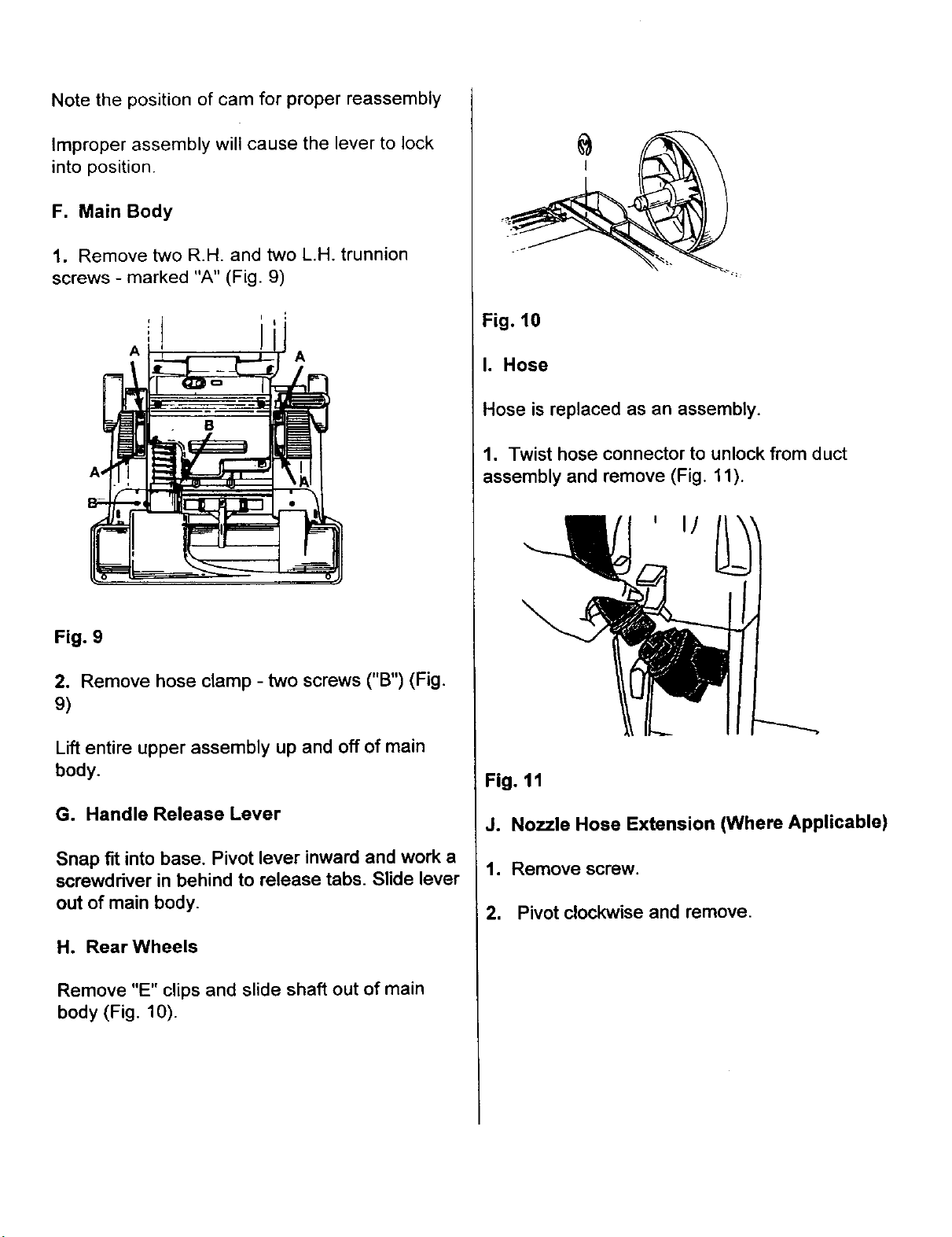
H. Rear Wheels
Remove "E" clips and slide shaft out of main
body (Fig. 10).
Fig. 10
I. Hose
Hose is replaced as an assembly.
1. Twist hose connector to unlock from duct
assembly and remove (Fig. 11).
\
Fig. 11
J. Nozzle Hose Extension (Where Applicable)
1. Remove screw.
2. Pivot clockwise and remove.
Loading ...
Loading ...
Loading ...