
Operator's Manual
CRAFTSMAN°
_i'ii
LAWN TRACTOR
20.0 HP, 42" Mower
Electric Start
Automatic Transmission
Model No.
917.27618
• EspaSol, p. 33
This product has a low emission engine which operates
differently from previously built engines. Before you start the
engine, read and understand this Owner's Manual.
IMPORTANT:
Read and follow all Safety
Rules and Instructionsbefore
operatingthis equipment.
For answers to your questions
about this product, Call:
1-800-659-5917
Sears Craftsman Help Line
5 am _5 pm, Mon - Sat
SEARS, ROEBUCK AND CO., HOFFMAN ESTATES, IL 60179 U.S.A.
Visit our Craftsman website:www.sears.com/craftsman

Warranty................................................2
SafetyRules..........................................3
ProductSpecifications...........................6
Assembly/Pre-Operation.......................7
Operation...............................................9
MaintenanceSchedule........................17
Maintenance ........................................ 17
Service and Adjustments ..................... 21
Storage ................................................ 28
Troubleshooting ................................... 29
Sears Service ........................ Back Cover
LIMITED WARRANTY ON CRAFTSMAN TRACTOR AND BATTERY
2-YEAR ON TRACTOR
When used and maintained according to the operator's manual instructions, if this
tractor fails due to a defect in material or workmanship within two years from the date of
purchase, call 1-800-4-MY-HOME® to arrange for free repair.
During the first 30 days of purchase, there will be no charge to service the product in
your home. For your convenience, in-home warranty service will still be available after
the first 30 days of purchase, but a trip charge will apply. This charge will be waived if
you transport the product to an authorized Craftsman drop-off iocation_ For the nearest
authorized location, call 1-800-4-MY-HOME®.
Tractor warranty coverage does not include:
• Expendable items which become worn during normal use, including but not limited to
biades, spark plugs, air cleaners, belts, and oil filters.
° Standard maintenance servicing, oil changes, or tune-ups,
° Tire replacement or repair caused by punctures from outside objects, such as nails,
thorns, stumps, or glass.
° Repairs necessary because of operator abuse, including but not limited to damage
caused by towing objects beyond the capability of the tractor, impacting objects that
bend the frame or crankshaft, or over-speeding the engine.
° Repairs necessary because of operator negligence, including but not limited to electri-
cal and mechanical damage caused by improper storage, failure to use the proper
grade and amount of engine oil, failure to keep the deck clear of flammable debris,
or failure to maintain the equipment according to the instructions contained in the
operator's manual.
° Engine (fuel system) cleaning or repairs necessary because of fuel determined to be
contaminated or oxidized (stale). In general, fuel should be used within 30 days of its
purchase date.
° Normal deterioration and wear of the exterior finishes, or product label replacement.
° The tractor battery, which is covered for only 90 days as stated below.
90-DAYS ON BATTERY
For nine_ (90) days from the date of purchase, if the battery included with this tractor is
defective _nmaterial or workmanship (our testing proves it will not hold a charge), it will
be replaced free of charge.
During the first 30 days of purchase, there will be no charges to replace the battery in
your home. For your convenience, in-home warranty service will still be available after
the first 30 days of purchase, but a trip charge will apply. This charge will be waived if
you transport the battery to an authorized Craftsman drop..off location. For the nearest
authorized location, call 1-800-4-MY-HOME®.
All tractor and battery warranty coverage is void if this product is used for commercial or
rental purposes.
This warranty applies only while this product is within the United States.
This warranty gives you specific legal rights, and you may also have other rights, which
vary, from state to state.
Sears, Roebuck and Co,, Hoffman Estates, IL 60179
2
A __
8"lkDANGER:" This cutting machine is capable of amputating hands and feet and
throwing objects. Failure to observe the following safety instructions could result
in serious injury or death.
_.LWARNING: In order to prevent ac-
cidental starting when setting up, trans-
porting, adjusting or making repairs,
always disconnect spark plug wire and
place wire where it cannot contact spark
plug.
_WARNING: Do not coast down a hill in
neutral, you may lose control of the tractor.
_WARNING: Tow only the attachments
that are recommended by and comply with
specifications of the manufacturer of your
tractor. Use common sense when towing.
Operate only at the lowest possible speed
when on a slope. Too heavy of a load,
while on a slope, is dangerous, Tires can
lose traction with the ground and cause
you to lose control of your tractor.
_,WARNING: Engine exhaust, some of
its constituents, and certain vehicle com-
ponents contain or emit chemicals known
to the State of California to cause cancer
and birth defects or other reproductive
harm°
_WARNING: Battery posts, terminals
and related accessories contain lead and
lead compounds, chemicals known to the
State of California to cause cancer and
birth defects or other reproductive harm.
Wash hands after handling.
I. GENERAL OPERATION
• Read, understand, and follow all
instructions on the machine and in the
manual before starting_
- Do not put hands or feet near rotating
parts or under the machine, Keep clear
of the discharge opening at all times_
• Only allow responsible adults, who are
familiar with the instructions, to operate
the machine.
• Clear the area of objects such as
rocks, toys, wire, etc. which could be
picked up and thrown by the blades.
• Be sure the area is clear of bystand-
ers before operating. Stop machine if
anyone enters the area.
• Never carry passengers.
• Do not mow in reverse unless abso-
lutely necessary. Always look down
and behind before and while backing.
• Never direct discharged material
toward anyone. Avoid discharging
material against a wall or obstruction°
Material may ricochet back toward the
operator. Stop the blades when cross-
ing gravel surfaces.
• Do not operate machine without the
entire grass catcher, discharge guard,
or other safety devices in place and
working.
• Slow down before turning.
° Never leave a running machine
unattended, Always turn off blades,
set parking brake, stop engine, and
remove keys before dismounting.
• Disengage blades when not mowing.
Shut off engine and wait for all parts to
come to a complete stop before clean-
ing the machine, removing the grass
catcher, or unclogging the discharge
guard_
° Operate machine only in daylight or
good artificial light°
• Do not operate the machine while
under the influence of alcohol or drugs.
• Watch for traffic when operating near
or crossing roadways.
• Use extra care when loading or unload-
ing the machine into a trailer or truck.
• Always wear eye protection when oper-
ating machine.
• Data indicates that operators, age 60
years and above, are involved in a
large percentage of riding mower-re-
lated injuries. These operators should
evaluate their ability to operate the
riding mower safely enough to protect
themselves and others from serious
injury.
° Follow the manufacturer's recommen-
dation for wheel weights or counter-
weights.
° Keep machine free of grass, leaves
or other debris build-up which can
touch hot exhaust / engine parts and
burn. Do not allow the mower to plow
leaves or other debris which can cause
build-up to occur. Clean any oil or fuel
spillage before operating or storing the
machine. Allow machine to cool before
storage.
II, SLOPE OPERATION
Slopesare a majorfactorrelatedto lossof
controland tip-overaccidents,whichcan
result in severeinjuryordeath. Opera-
tion on all slopesrequiresextracaution. If
you cannotback up theslope or if you feel
uneasyon it, do notmowit.
• Mowup anddownslopes,notacross.
• Watchfor holes,ruts, bumps,rocks,or
otherhiddenobjects. Uneventerrain
couldoverturnthe machine.Tallgrass
can hideobstacles.
• Choosea lowgroundspeedsothat
you will nothaveto stopor shiftwhile
on the slope.
• Donot mowon wet grass.Tires may
losetraction°
Alwayskeepthe machinein gearwhen
goingdownslopes,Do not shiftto
neutralandcoast downhill,
• Avoid starting, stopping, or turning on
a slope. If the tires lose traction, dis-
engage the blades and proceed slowly
straight down the slope.
° Keep all movement on the slopes slow
and gradual, Do not make sudden
changes in speed or direction, which
could cause the machine to roll over.
° Use extra care while operating ma-
chine with grass catchers or other at-
tachments; they can affect the stability
of the machine. Do no use on steep
slopes.
• Do not try to stabilize the machine by
putting your foot on the ground.
• Do not mow near drop-offs, ditches,
or embankments. The machine could
suddenly roll over if a wheel is over the
edge or if the edge caves in.
III, CHILDREN
Tragic accidents can occur if the operator
is not alert to the presence of children.
Children are often attracted to the machine
and the mowing activity. Never assume
that children will remain where you last
saw them,
• Keep children out of the mowing area
and in the watchful care of a respom
sible adult other than the operator.
• Be alert and turn machine off if a child
enters the area.
° Before and while backing, look behind
and down for small children.
• Never carry children, even with the
blades shut off. They may fall off and
be seriously injured or interfere with
safe machine operation. Children who
have been given rides in the past may
suddenly appear in the mowing area
for another ride and be run over or
backed over by the machine,
o Never allow children to operate the
machine.
• Use extra care when approaching blind
corners, shrubs, trees, or other objects
that may block your view of a child,
IV. TOWING
• Tow only with a machine that has a
hitch designed for towing. Do not at-
tach towed equipment except at the
hitch point.
• Follow the manufacturer's recom-
mendation for weight limits for towed
equipment and towing on slopes.
• Never allow children or others in or on
towed equipment.
• On slopes, the weight of the towed
equipment may cause loss of traction
and loss of control.
° Travel slowly and allow extra distance
to stop.
V, SERVICE
SAFE HANDLING OF GASOLINE
To avoid personal injury or property
damage, use extreme care in handling
gasoline. Gasoline is extremely flammable
and the vapors are explosive.
• Extinguish all cigarettes, cigars, pipes,
and other sources of ignition,
• Use onty approved gasoline container.
• Never remove gas cap or add fuel with
the engine running, Nlow engine to
cool before refueling.
• Never fuel the machine indoors.
• Never store the machine or fuel con-
tainer where there is an open flame,
spark, or pilot light such as on a water
heater or other appliances.
° Never fill containers inside a vehicle
or on a truck or trailer bed with plastic
liner. Always place containers on the
ground away from your vehicle when
filling.
4
• Remove gas-powered equipment from
the truck or trailer and refuel it on the
ground. If this is not possible, then
refuel such equipment with a portable
container, rather than from a gasoline
dispenser nozzle.
• Keep the nozzle in contact with the rim
of the fuel tank or container opening at
all times until fueling is complete, Do
not use a nozzle lock-open device.
• tf fuel is spilled on clothing, change
clothing immediately.
o Never overfill fuel tank. Replace gas
cap and tighten securely.
GENERAL SERVICE
• Never operate machine in a closed
area°
• Keep all nuts and bolts tight to be sure
the equipment is in safe working condi-
tion.
• Never tamper with safety devices.
Check their proper operation regularly.
• Keep machine free of grass, leaves, or
other debris build-up. Clean oil or fuel
spillage and remove any fuel-soaked
debris. Allow machine to cool before
storing_
• tf you strike a foreign object, stop and
inspect the machine. Repair, if neces-
sary, before restarting.
• Never make any adjustments or repairs
with the engine running.
• Checkgrass catcher components and
the discharge guard frequently and
replace with manufacturer's recom-.
mended parts, when necessary.
° Mower blades are sharp. Wrap the
blade or wear gloves, and use extra
caution when servicing them.
• Check brake operation frequently. Ad-
just and service as required.
° Maintain or replace safety and instruc-
tion labels, as necessary.
• Be sure the area is clear of bystand-
ers before operating, Stop machine if
anyone enters the area.
° Never carry passengers.
• Do not mow in reverse unless abso-
lutely necessary. Always look down
and behind before and while backing.
° Never carry children, even with the
blades shut off. They may fall off and
be seriously injured or interfere with
safe machine operation. Children who
have been given rides in the past may
suddenly appear in the mowing area
for another ride and be run over or
backed over by the machine,
• Keep children out of the mowing area
and in the watchful care of a respon-
sible adult other than the operator.
• Be alert and turn machine off if a child
enters the area.
• Before and while backing, look behind
and down for small children.
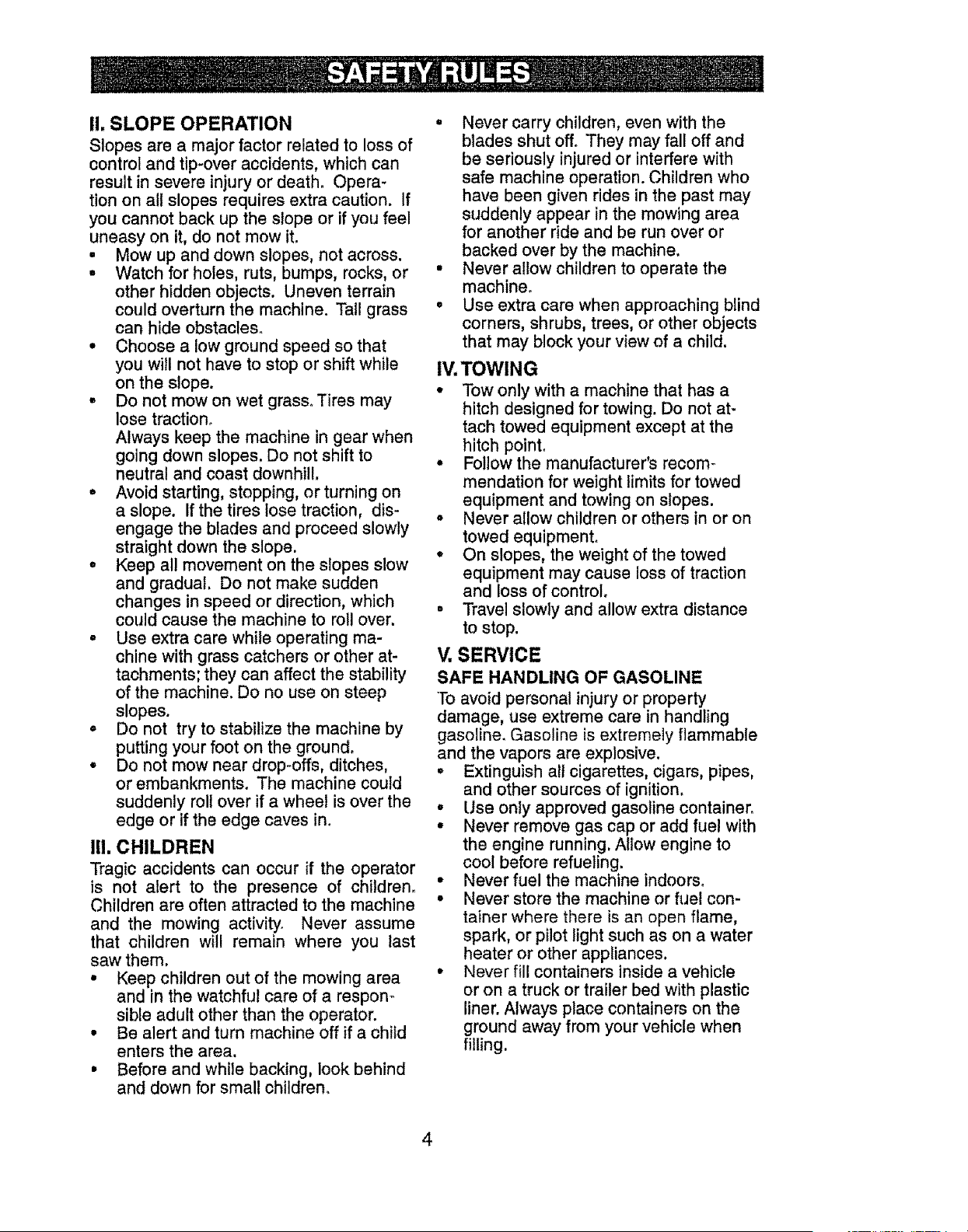
, Mow up and down slopes (15 0 Max),
not across,
° Choose a low ground speed so that
you will not have to stop or shift while
on the slope.
• Avoid starting, stopping, or turning on
a slope. If the tires lose traction, dis-
engage the blades and proceed slowly
straight down the s!ope.
• If machine stops while going uphill,
disengage blades, shift into reverse
and back down slowly.
• Do not turn on slopes unless neces-
sary, and then, turn slowly and gradu-
ally downhill, if possible.
PRODUCT SPECIFICATIONS
Gasoline Capacity
and Type:
Oil Type
(AP!-SG-SL):
Oil Capacity:
2.50 Gallons
Unleaded Regular
SAE 10W30 (above
32°F)
SAE 5W30 (below 32°F
Wi Filter: 51 oz.
W/O Filter: 35 oz.
Spark Plug: Champion RC12YC
(Gap: .030")
Ground Speed Forward: 0-5,5
Reverse: 0-2,4
Charging System: 15 Amps @ 3600 RPM
Battery: Amp/Hr: 35
Min. CCA: 280
Case size: U1R
Blade Bolt Torque: 45-55 Ft. Lbs.
CONGRATULATIONS on your purchase
of a new tractor. It has been designed,
engineered and manufactured to give
you the best possible dependability and
performance.
Should you experience any problem you
cannot easily remedy, please contact a
Sears or other qualified service center.
We have competent, well-trained repre-
sentatives and the proper tools to service
or repair this tractor.
Please read and retain this manual. The
instructions will enable you to assemble
and maintain your tractor properly. Always
observe the "SAFETY RULES".
CUSTOMER RESPONSIBILITIES
• Read and observe the safety rules.
° Follow a regular schedule in main-
taining, caring for and using your tractor.
° Follow the instructions under"Mainte-
nance" and "Storage" sections of this
owner's manual,
_WARNING: This tractor is equipped
with an internal combustion engine and
should not be used on or near any unim-
proved forest-covered, brush-covered or
grass-covered land unless the engine's
exhaust system is equipped with a spark
arrester meeting applicable local or state
laws (if any). If aspark arrester is used, it
should be maintained in effective working
order by the operator.
tn the state of California the above is re-
quired by law (Section 4442 of the Califor-
nia Public Resources Code). Other states
may have similar laws. Federal laws apply
on federal lands. A spark arrester for the
muffler is available through your nearest
Sears service center (See REPAIR PARTS
manual).
REPAIR PROTECTION
AGREEMENTS
Congratulations on making a smart pur-
chase.Your new Craftsman® product is
designed and manufactured for years of
dependable operation. But like all products,
it may require repair from time to time. That's
when having a Repair Protection Agreement
can save you money and aggravation.
Purchase a Repair Protection Agreement
now and protect yourself from unexpected
hassle and expense.
Here's what's included in the Agreement:
° Expert service by our 12,000 profe-
sional repair specialists.
* Unlimited service and no charge for
parts and labor on all covered repairs.
o Product replacement if your covered
product can't be fixed.
° Discount of 10% from regular price of
service and service-related parts not
covered by the agreement; also, 10%
off regular price of preventive mainte-
nance check.
. Fast help by phone - phone sup-
port from a Sears representative on
products requiring in-home repair, plus
convenient repair scheduling.
Once you purchase the Agreement, a
simple phone call is all that it takes for you
to schedule service. You can call anytime
day or night, or schedule a service ap-
pointment online,
Sears has over 12,000 professional repair
specialists, who have access to over 4.5
million quality parts and accessories.
That's the kind of professionalism you can
count on to help prolong the life of your
new purchase for years to come. Purchase
your Repair Protection Agreement todayl
Some limitations and exclusions apply.
For prices and additional information
call 1-800-827-6655.
SEARS INSTALLATION SERVICE
For Sears professional installation of home
appliances, garage door openers, water
heaters, and other major home items, in
the U.S.A. call 1-800-4-MY-HOME®
6
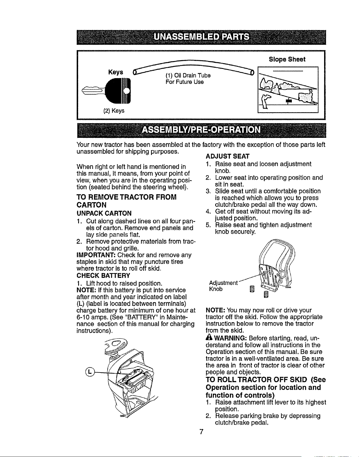
Slope Sheet
Keys
(2) Keys
(1) Oil Drain Tube
For Future Use
Your new tractor has been assembled at the factory with the exception of those parts left
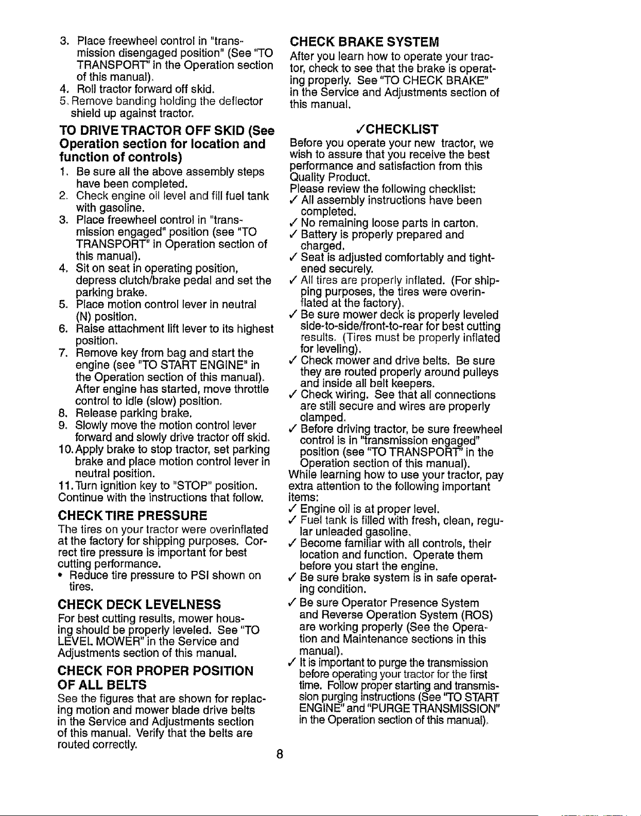
unassembled for shipping purposes, ADJUST SEAT
1. Raise seat and loosen adjustment
knob,
2o Lower seat into operating position and
sit in seat.
3, Slide seat until a comfortable position
is reached which allows you to press
clutch/brake pedal all the way down.
4. Get off seat without moving its ad-
justed position.
5. Raise seat and tighten adjustment
knob securely,
When right or left hand is mentioned in
this manual, it means, from your point of
view, when you are in the operating posi-
tion (seated behind the steering wheel).
TO REMOVE TRACTOR FROM
CARTON
UNPACK CARTON
1. Cut along dashed lines on all four pan-
els of carton, Remove end panels and
lay side panels flat.
2. Remove protective materials from trac-
tor hood and grille.
IMPORTANT: Check for and remove any
staples in skid that may puncture tires
where tractor is to roll off skid,
CHECK BATTERY
1. Lift hood to raised position.
NOTE: If this battery is put into service
after month and year indicated on label
(L) (label is located between terminals)
charge battery for minimum of one hour at
6-10 amps, (See "BATTERY" in Mainte-
nance section of this manual for charging
instructions).
Adjustment
Knob
I
NOTE: You may now roll or drive your
tractor off the skid, Follow the appropriate
instruction below to remove the tractor
from the skid,
WARNING: Before starting, read, un-
derstand and follow all instructions in the
Operation section of this manual. Be sure
tractor ts in a welloventilated area_ Be sure
the area in front of tractor is clear of other
people and objects,
TO ROLL TRACTOR OFF SKID (See
Operation section for location and
function of controls)
1o Raise attachment lift lever to its highest
position.
2. Release parking brake by depressing
clutch!brake pedal,
3. Placefreewheelcontrolin "trans-.
missiondisengagedposition"(See"TO
TRANSPORT"in the Operationsection
of this manual).
4. Rolltractorforwardoff skid°
5oRemovebandingholdingthe deflector
shieldup againsttractor.
TO DRIVE TRACTOR OFF SKID (See
Operation section for location and
function of controls)
1_ Be sure all the above assembly steps
have been completed.
2. Check engine oil level and fill fuel tank
with gasoline.
3. Place freewheel control in "trans-
mission engaged" position (see "TO
TRANSPORT" in Operation section of
this manual).
4. Sit on seat in operating position,
depress clutch/brake pedal and set the
parking brake°
5o Place motion control lever in neutral
(N) position,
6. Raise attachment lift lever to its highest
position.
7. Remove key from bag and start the
engine (see "TO START ENGINE" in
the Operation section of this manual).
After engine has started, move throttle
control to idle (slow) position.
8. Release parking brake.
9. Slowly move the motion control lever
forward and slowly drive tractor off skid.
10. Apply brake to stop tractor, set parking
brake and place motion control lever in
neutral position.
11.Turn ignition key to "STOP" position.
Continue with the instructions that follow.
CHECK TIRE PRESSURE
The tires on your tractor were overinflated
at the factory for shipping purposes. Cor-
rect tire pressure is important for best
cutting performance.
° Reduce tire pressure to PSI shown on
tires.
CHECK DECK LEVELNESS
For best cutting results, mower hous-
ing should be properly leveled. See "TO
LEVEL MOWER" in the Service and
Adjustments section of this manual.
CHECK FOR PROPER POSITION
OF ALL BELTS
See the figures that are shown for replac-
ing motion and mower blade drive beIts
in the Service and Adjustments section
of this manual Verify that the belts are
routed correctly.
8
CHECK BRAKE SYSTEM
After you learn how to operate your trac-
tor, check to see that the brake is operat-
ing properly. See "TO CHECK BRAKE"
in the Service and Adjustments section of
this manual.
,/CHECKLIST
Before you operate your new tractor, we
wish to assure that you receive the best
_erformance and satisfaction from this
uality Product.
Please review the following checklist:
_" All assembly instructions have been
completed.
v" No remaining loose parts in carton,
,/' Battery is properly prepared and
charged.
#" Seat is adjusted comfortably and tight-
ened securely.
/ All tires are properly inflated. (For ship-
ping purposes, the tires were overin-
flared at the factory).
,," Be sure mower deck is properly leveled
side-to-slde/front-to-rear for best cutting
results. (Tires must be properly inflated
for leveling).
v" Check mower and drive belts. Be sure
they are routed properly around pulleys
and inside all belt keepers°
•/ Check wiring. See that all connections
are still secure and wires are properly
clamped.
v" Before driving tractor, be sure freewheel
control is in '"transmission engaged"
(_osition (see "TO TRANSPORT" in the
peration section of this manual).
While learning how to use your tractor, pay
extra attention to the following important
items:
,/Engine oi! is at proper level.
,/Fuel tank is fiIled with fresh, clean, regu-
lar unleaded gasoline.
," Become familiar with all controls, their
location and function. Operate them
before you start the engine.
v" Be sure brake system is in safe operat-
ing condition.
,/Be sure Operator Presence System
and Reverse Operation System (ROS)
are working properly (See the Opera..
tion and Maintenance sections in this
manual)°
/ It is important to purge the transmission
before operating your tractor for the first
time. Fol!ow proper starting and transmis-
sion purging instructions (See "TO START
ENGINE" and "PURGE TRANSMISSION"
in the Operation section of this manual).
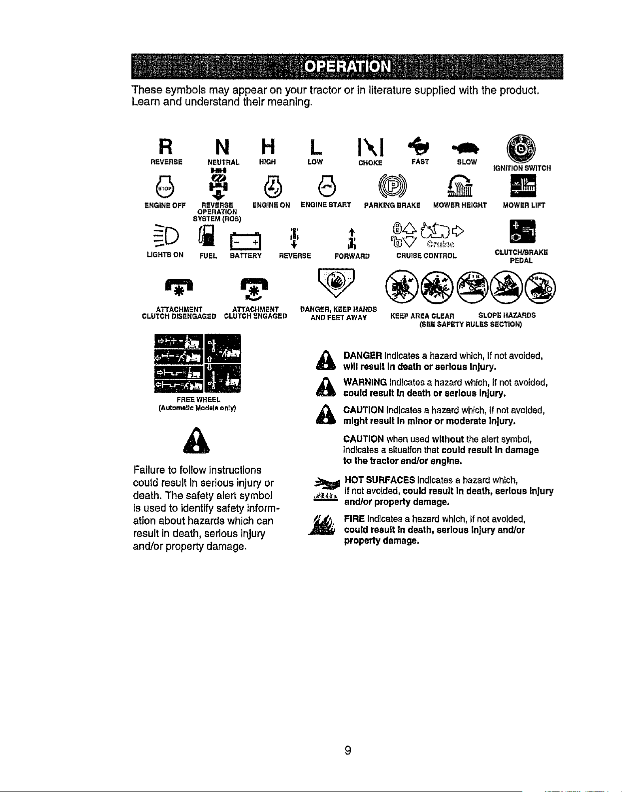
Thesesymbolsmayappearon yourtractoror in literaturesuppliedwiththeproduct.
Learnand understandtheir meaning,
R N H L I',,I
REVERSE NEUTRAL HIGH LOW CHOKE FAST SLOW
IFm4
ENGINE OFF REVERSE ENGINE ON ENGINE START PARKING BRAKE MOWER HEIGHT
OPERATION
SYSTEM (ROS)
FUEL BATTERY
,v,
ATTACHMENT ATTACHMENT
CLUTCH DISENGAGED CLUTCH ENGAGED
FREEWHEEL
(AutomaUeMode_eonly)
;|; *
;i;
REVERSE FORWARD
DANGER, KEEP HANDS
AND FEET AWAY
tGNIT!ON SWITCH
MOWER LIFT
®.o.11 1;1)o
CRUtSE CONTROL CLUTCH/BRAKE
PEDAL
KEEP AREA CLEAR SLOPE HAZARDS
(SEE SAFETY RULES SECTION)
&
Failure to follow instructions
could result In serious injury or
death. The safety alert symbol
Is used to identify safety inform-
ation about hazards which can
result in death, serious injury
and/or property damage,
DANGERindicates a hazard which,if not avoided,
will result In death or serious Injury.
WARNING indicatesa hazard which,If notavoided,
could result In death or serious Injury.
CAUTION indicatesa hazardwhich,If notavoided,
might result In minor or moderate Injury.
CAUTION when usedwithout the alert symbol,
indicatesa situationthat could result In damage
to the tractor and/or engine,
HOT SURFACES indicatesa hazard which,
tfnot avoided,could result In death, serious Injury
and/or property damage.
FIRE indicatesa hazard which,tfnotavoided,
could result In death, serious Injury and/or
property damage.
9
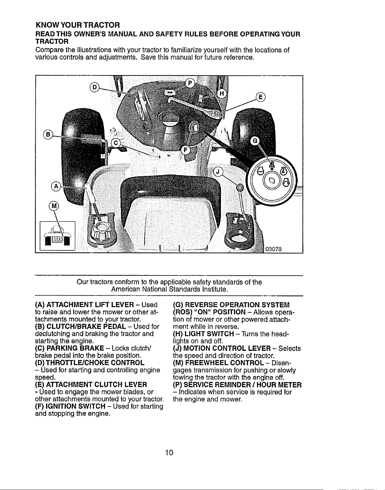
KNOW YOUR TRACTOR
READ THIS OWNER'S MANUAL AND SAFETY RULES BEFORE OPERATING YOUR
TRACTOR
Compare the illustrations with your tractor to familiarize yourself with the locations of
various controls and adjustments. Save this manual for future reference.
....... 03078
Our tractors conform to the applicable safety standards of the
American National Standards Institute.
(A) ATTACHMENT LIFT LEVER - Used
to raise and lower the mower or other at-
tachments mounted to your tractor.
(B) CLUTCH/BRAKE PEDAL - Used for
declutching and braking the tractor and
starting the engine.
(C) PARKING BRAKE - Locks clutch/
brake pedal into the brake position.
(D) THROTTLE/CHOKE CONTROL
- Used for starting and controlling engine
speed.
(E) ATTACHMENT CLUTCH LEVER
- Used to engage the mower blades, or
other attachments mounted to your tractor.
(F) IGNITION SWITCH - Used for starting
and stopping the engine.
(G) REVERSE OPERATION SYSTEM
(ROS) "ON" POSITION - Allows opera-
tion of mower or other powered attach-
ment while in reverse.
(H) LIGHT SWITCH- Turns the head-
lights on and off,
(J) MOTION CONTROL LEVER -Selects
the speed and direction of tractor.
(M) FREEWHEEL CONTROL - Disen-
gages transmission for pushing or slowly
towing the tractor with the engine off,
(P) SERVICE REMINDER / HOUR METER
- Indicates when service is required for
the engine and mower.
10
The operation of any tractor can result in foreign objects thrown into the
eyes, which can result in severe eye damage. Always wear safety glasses
or eye shields while operating your tractor or performing any adjustments
or repairs. We recommend standard safety glasses or a wide vision safety
mask worn over spectacles.
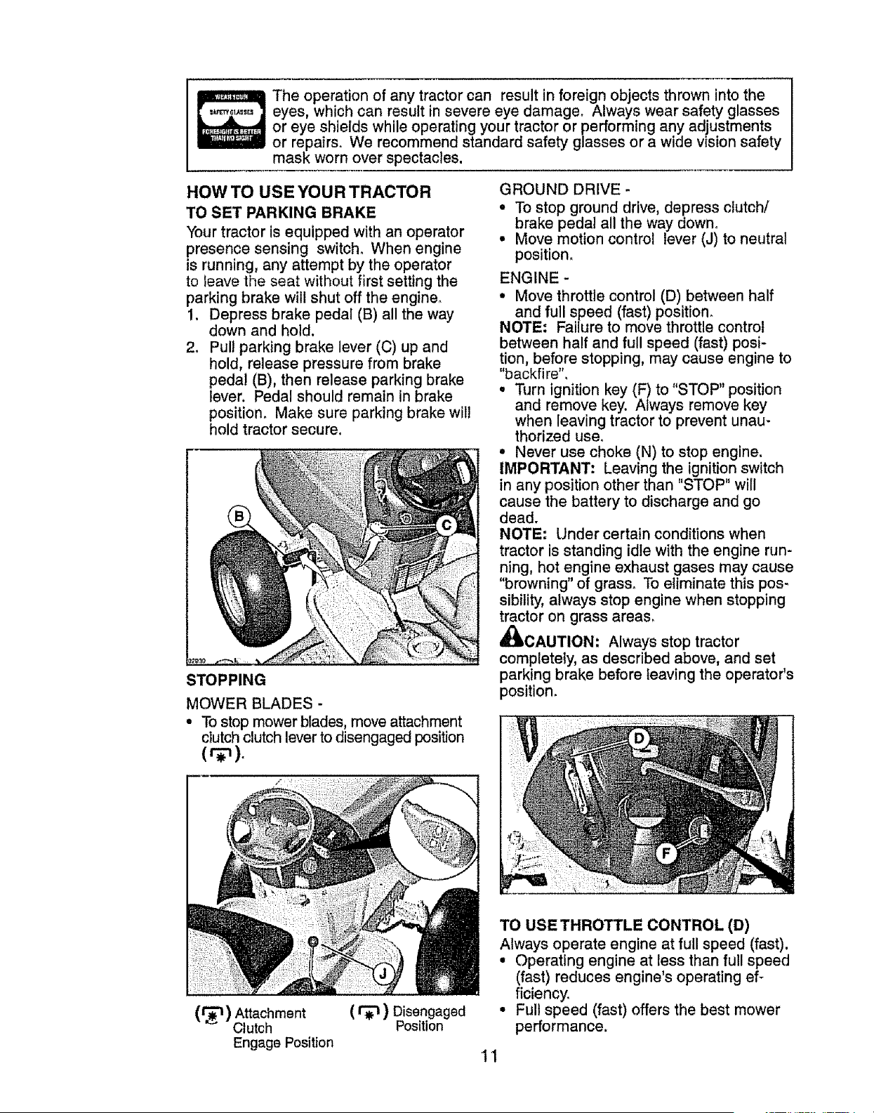
HOW TO USE YOUR TRACTOR
TO SET PARKING BRAKE
Your tractor is equipped with an operator
presence sensing switch° When engine
is running, any attempt by the operator
to leave the seat without first setting the
parking brake will shut off the engine.
1. Depress brake pedal (B) all the way
down and hold.
2. Pull parking brake lever (C) up and
hold, release pressure from brake
pedal (B), then release parking brake
lever. Pedal should remain in brake
position. Make sure parking brake will
hold tractor secure.
STOPPING
MOWER BLADES -
• To stop mower blades, move attachment
clutch clutch lever to disengaged position
(.r_) Attachment ( _ ) Disengaged
Clutch Position
Engage Position
GROUND DRIVE -
• To stop ground drive, depress clutch/
brake pedal all the way down.
• Move motion control lever (J) to neutra!
position.
ENGINE -
• Move throttle control (D) between half
and full speed (fast) position.
NOTE: Failure to move throttle control
between half and full speed (fast) posi-
tion, before stopping, may cause engine to
"backfire '°,
• Turn ignition key (F) to "STOP" position
and remove key. Always remove key
when leaving tractor to prevent unau-
thorized use°
• Never use choke (N) to stop engine.
IMPORTANT: Leaving the ignition switch
in any position other than "STOP" will
cause the battery to discharge and go
dead.
NOTE: Under certain conditions when
tractor is standing idle with the engine run-
ning, hot engine exhaust gases may cause
"browning" of grass. To eliminate this pos-
sibility, always stop engine when stopping
tractor on grass areas.
_JIkOAUTION: Always stop tractor
completely, as described above, and set
parking brake before leaving the operator's
position.
TO USE THROTTLE CONTROL (D)
Always operate engine at full speed (fast).
• Operating engine at less than full speed
(fast) reduces engine's operating ef-
ficiency,
• Full speed (fast) offers the best mower
performance.
11
TO MOVE FORWARD AND
BAC KWAR D
The direction and speed of movement is
controlled by the motion control lever. (J)
1. Start tractor with motion control lever in
neutral (N) position.
2, Release parking brake°
3o Slowly move motion control lever to
desired position,
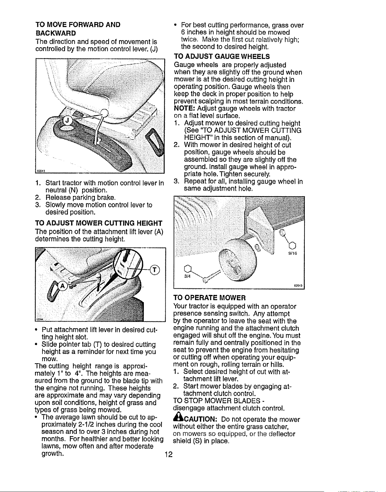
TO ADJUST MOWER CUTTING HEIGHT
The position of the attachment lift lever (A)
determines the cutting height.
• Put attachment lift lever in desired cut-
ting height slot.
• Slide pointer tab (T) to desired cutting
height as a reminder for next time you
mow_
The cutting height range is approxi-
mately t" to 4". The heights are mea_
sured from the ground to the blade tip with
the engine not running. These heights
are approximate and may vary depending
upon soil conditions, height of grass and
types of grass being mowed.
. The average lawn should be cut to ap-
proximately 2-1/2 inches during the cool
season and to over 3 inches during hot
months. For healthier and better looking
lawns, mow often and after moderate
growth. 12
• For best cutting performance, grass over
6 inches in height should be mowed
twice. Make the first cut relatively high;
the second to desired height,
TO ADJUST GAUGE WHEELS
Gauge wheels are properly adjusted
when they are slightly off the ground when
mower is at the desired cutting height in
operating position° Gauge wheels then
keep the deck in proper position to help
prevent scalping in most terrain conditions_
NOTE: Adjust gauge wheels with tractor
on a flat level surface.
1, Adjust mower to desired cutting height
(See 'q'O ADJUST MOWER CUTTING
HEIGHT" in this section of manual),
2. With mower in desired height of cut
position, gauge wheels should be
assembled so they are slightly off the
ground° Install gauge wheel in appro-
priate hole. Tighten securely.
3. Repeat for all, installing gauge wheel in
same adjustment hole,
9/t6
TO OPERATE MOWER
Your tractor is equipped with an operator
presence sensing switch, Any attempt
by the operator to leave the seat with the
engine running and the attachment clutch
engaged will shut off the engine° You must
remain fully and centrally positioned in the
seat to prevent the engine from hesitating
or cutting off when operating your equip-
ment on rough, roiling terrain or hills.
1. Select desired height of cut with at-
tachment lift lever,
2. Start mower blades by engaging at-
tachment clutch control.
TO STOP MOWER BLADES -
disengage attachment clutch control,
_CAUTION: Do not operate the mower
without either the entire grass catcher,
on mowers so equipped, or the deflector
shield (S) in place.
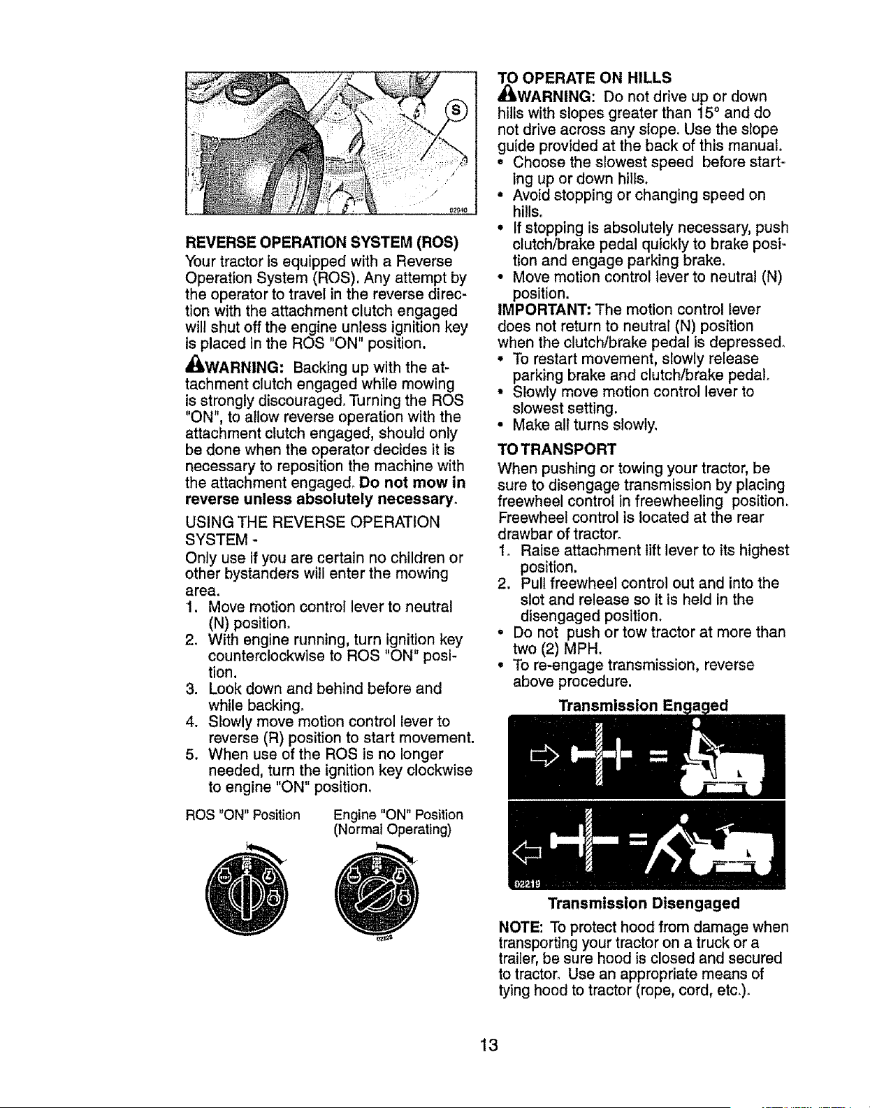
REVERSE OPERATION SYSTEM (ROS)
Your tractor is equipped with a Reverse
Operation System (ROS), Any attempt by
the operator to travel in the reverse direc-
tion with the attachment clutch engaged
will shut off the engine unless ignition key
is placed in the ROS "ON" position.
_WARNING: Backing up with the at-
tachment clutch engaged while mowing
is strongly discouraged, Turning the ROS
"ON", to allow reverse operation with the
attachment clutch engaged, should only
be done when the operator decides it is
necessary to reposition the machine with
the attachment engaged_ Do not mow in
reverse unless absolutely necessary,
USING THE REVERSE OPERATION
SYSTEM -
Only use if you are certain no children or
other bystanders wl!l enter the mowing
area.
1. Move motion control lever to neutral
(N) position,
2o With engine running, turn ignition key
counterclockwise to ROS "ON" posi-
tion.
3. Look down and behind before and
while backing,
4. Slowly move motion control lever to
reverse (R) position to start movement.
5. When use of the ROS is no longer
needed, turn the ignition key clockwise
to engine "ON" position,
ROS "ON" Position Engine "ON" Position
(Normal Operating)
_ OPERATE ON HILLS
WARNING: Do not drive up or down
hillswith slopes greater than 15° and do
not drive across any slope° Use the slope
guide provided at the back of this manual.
• Choose the slowest speed before start-
ing up or down hills,
• Avoid stopping or changing speed on
hills°
• If stopping is absolutely necessary, push
clutch/brake pedal quickly to brake posi-
tion and engage parking brake.
• Move motion control lever to neutral (N)
position.
IMPORTANT: The motion control lever
does not return to neutral (N) position
when the clutch/brake pedal is depressed,
° To restart movement, slowly release
parking brake and clutch/brake pedal
• Slowly move motion control lever to
slowest setting.
• Make all turns siowly_
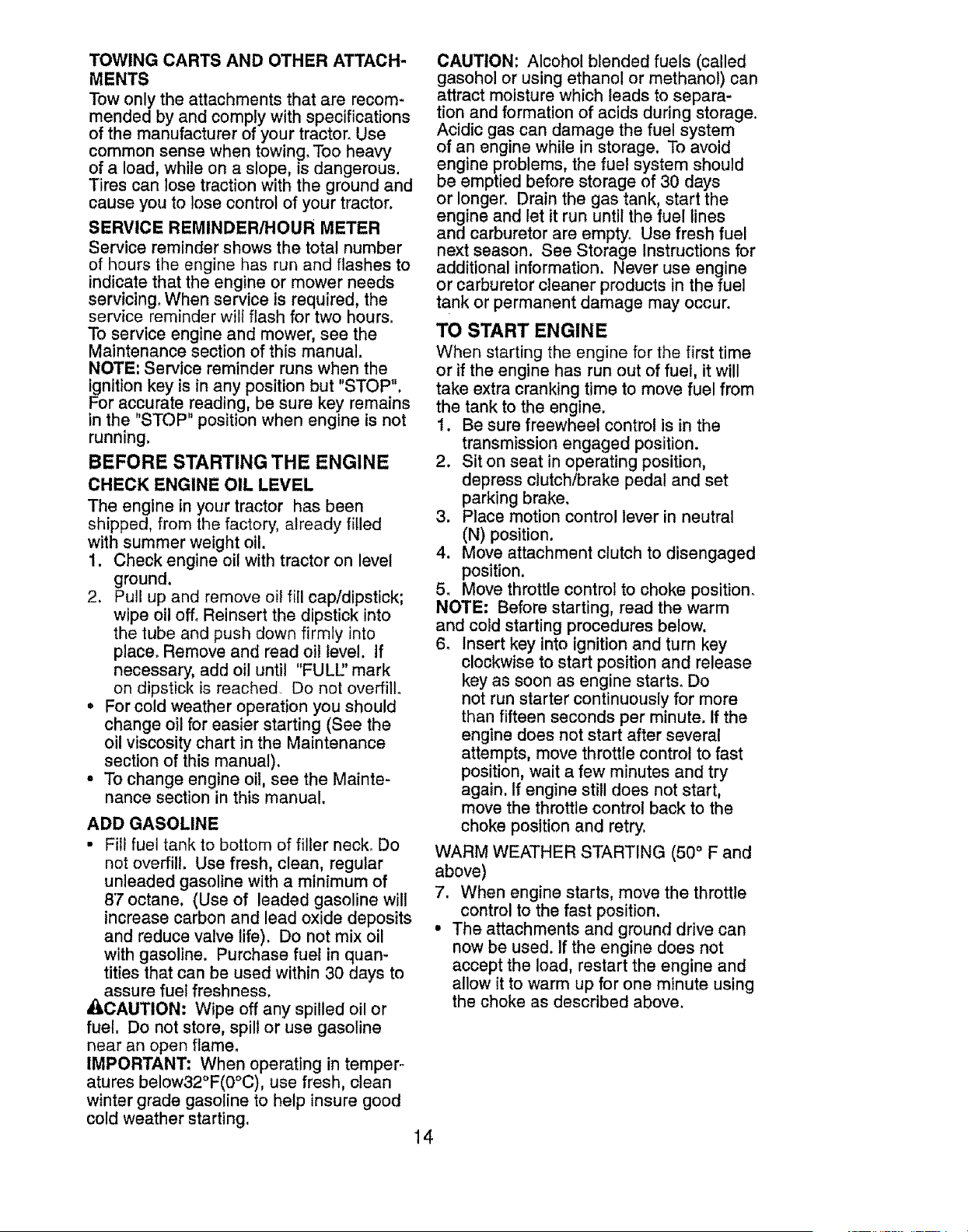
TO TRANSPORT
When pushing or towing your tractor, be
sure to disengage transmission by placing
freewheel control in freewheeling position.
Freewheel control is located at the rear
drawbar of tractor°
1. Raise attachment lift lever to its highest
position.
2, Pull freewheel control out and into the
slot and release so it is held in the
disengaged position.
• Do not push or tow tractor at more than
two (2) MPH.
° To re-engage transmission, reverse
above procedure.
Transmission En
Transmission Disengaged
NOTE: To protect hood from damage when
transporting your tractor on a truck or a
trailer, be sure hood is closed and secured
to tractor. Use an appropriate means of
tying hood to tractor (rope, cord, etc.).
13
TOWINGCARTSAND OTHERATTACH-
MENTS
Towonly the attachments that are recom-
mended by and comply with specifications
of the manufacturer of your tractor. Use
common sense when towing. Too heavy
of a load, while on a slope, is dangerous.
Tires can lose traction with the ground and
cause you to lose control of your tractor.
SERVICE REMINDER/HOUR METER
Service reminder shows the total number
of hours the engine has run and flashes to
indicate that the engine or mower needs
servicing. When service is required, the
service reminder will flash for two hours.
To service engine and mower, see the
Maintenance section of this manual.
NOTE: Service reminder runs when the
ignition key is in any position but "STOP",
For accurate reading, be sure key remains
in the "STOP" position when engine is not
running.
BEFORE STARTING THE ENGINE
CHECK ENGINE OIL LEVEL
The engine in your tractor has been
shipped, from the factory, already filled
with summer weight oil.
1. Check engine oil with tractor on level
ground.
2. Pull up and remove oil fill cap/dipstick;
wipe oil off, Reinsert the dipstick into
the tube and push down firmly into
place. Remove and read oil level. If
necessary, add oil until "FULU' mark
on dipstick is reached. Do not overfill.
• For cold weather operation you should
change oil for easier starting (See the
oil viscosity chart in the Maintenance
section of this manual).
° To change engine oil, see the Mainte-
nance section in this manual.
ADD GASOLINE
• Fill fuel tank to bottom of filler neck, Do
not overfill. Use fresh, clean, regular
unleaded gasoline with a minimum of
87 octane, (Use of leaded gasoline will
increase carbon and lead oxide deposits
and reduce valve life). Do not mix oil
with gasoline. Purchase fuel in quan-
tities that can be used within 30 days to
assure fuel freshness.
_.CAUTION: Wipe off any spilled oil or
fuel, Do not store, spill or use gasoline
near an open flame,
IMPORTANT: When operating in temper-
atures below32°F(O°C), use fresh, clean
winter grade gasoline to help insure good
cold weather starting,
14
CAUTION: Alcohol blended fuels (called
gasohol or using ethanol or methanol) can
attract moisture which leads to separa-
tion and formation of acids during storage.
Acidic gas can damage the fue! system
of an engine while in storage. To avoid
engine problems, the fuel system should
be emptied before storage of 30 days
or longer. Drain the gas tank, start the
engine and let it run until the fuel lines
and carburetor are empty. Use fresh fuel
next season. See Storage Instructions for
additional information. Never use engine
or carburetor cleaner products in the fuel
tank or permanent damage may occur.
TO START ENGINE
When starting the engine for the first time
or if the engine has run out of fuel, it will
take extra cranking time to move fuel from
the tank to the engine.
1. Be sure freewheel control is in the
transmission engaged position.
2. Sit on seat in operating position,
depress clutch/brake pedal and set
parking brake.
3. Place motion control lever in neutral
(N) position.
4. Move attachment clutch to disengaged
position.
5. Move throttle control to choke position.
NOTE: Before starting, read the warm
and cold starting procedures below.
6. Insert key into ignition and turn key
clockwise to start position and release
key as soon as engine starts. Do
not run starter continuously for more
than fifteen seconds per minute. If the
engine does not start after several
attempts, move throttle control to fast
position, wait a few minutes and try
again. If engine still does not start,
move the throttle control back to the
choke position and retry.
WARM WEATHER STARTING (50 ° F and
above)
7. When engine starts, move the throttle
control to the fast position,
• The attachments and ground drive can
now be used. If the engine does not
accept the load, restart the engine and
allow it to warm up for one minute using
the choke as described above.
COLDWEATHERSTARTING( 50° F and
below)
7. When engine starts, leave throttle
control in choke position until engine
warms up and begins to run roughly.
Once rough running begins, imme-
diately move the throttle control to the
fast position. Engine warm-up may
take from several seconds to several
minutes (the colder the temperature,
the longer the warm-up).
AUTOMATIC TRANSMISSION WARM UP
Before driving the unit in cold weather,
the transmission should be warmed up as
follows:
1. Be sure the tractor is on level ground.
2. Place the motion control lever in
neutral° Release the parking brake
and let the clutch/brake slowly return
to operating position.
3. Allow one minute for transmission to
warm up. This can be done during
the engine warm up period,
° The attachments can also be used dur-
ing the engine warm-up period after the
transmission has been warmed up.
NOTE: If at a high altitude (above 3000
feet) or in cold temperatures (below 32 F)
the carburetor fuel mixture may need to
be adjusted for best engine performance
(see "TO ADJUST CARBURETOR" in the
Service and Adjustments section of this
manual).
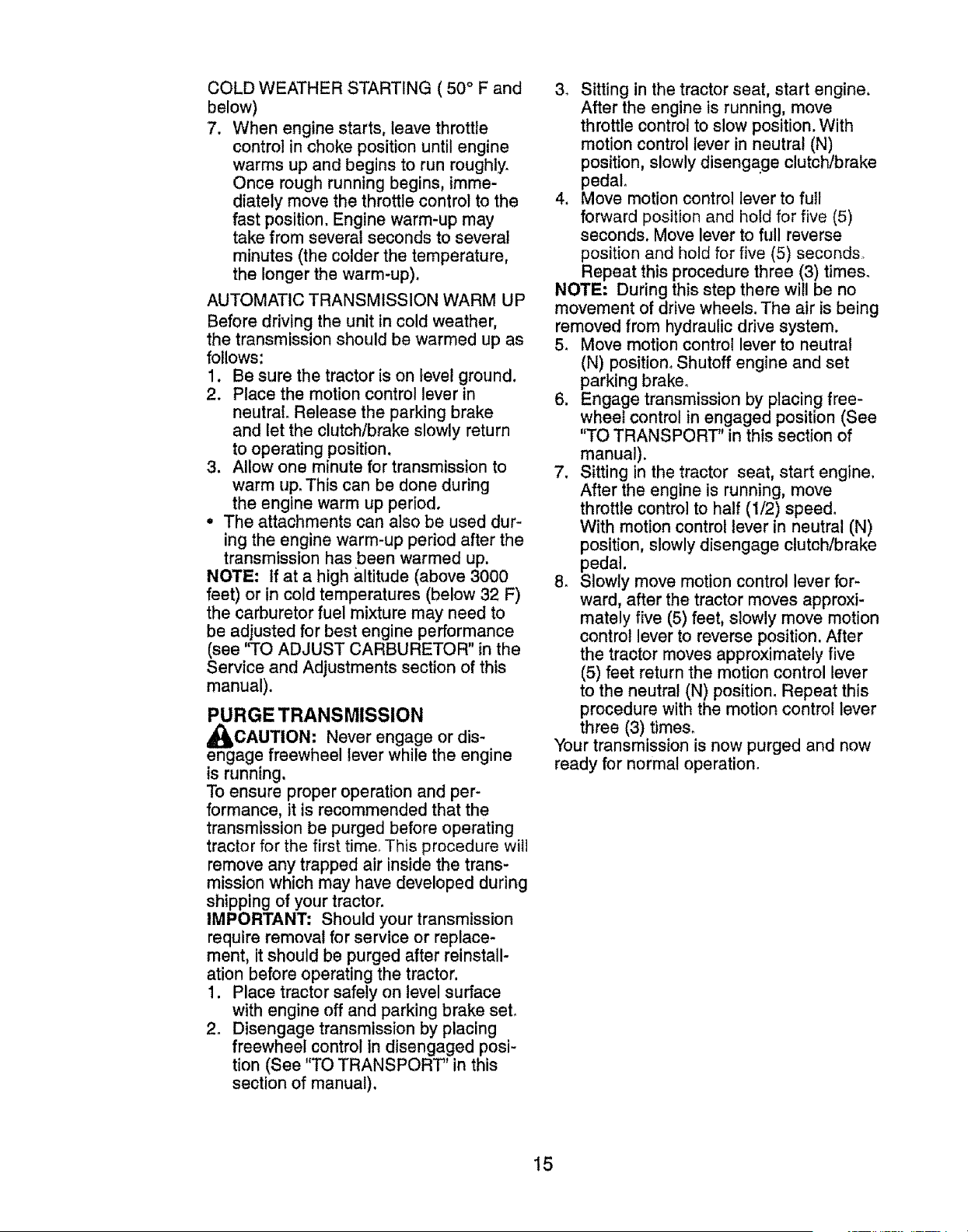
PURGE TRANSMISSION
_)&CAUTION: Never engage or dis-
engage freewheel lever while the engine
is running.
To ensure proper operation and per-
formance, it is recommended that the
transmission be purged before operating
tractor for the first time, This procedure will
remove any trapped air inside the trans-
mission which may have developed during
shipping of your tractor.
IMPORTANT; Should your transmission
require removal for service or replace-
ment, it should be purged after reinstall-
ation before operating the tractor.
1. Place tractor safely on level surface
with engine off and parking brake seL
2. Disengage transmission by placing
freewheel control in disengaged posi-
tion (See "TO TRANSPORT" in this
section of manual),
3. Sitting in the tractor seat, start engine.
After the engine is running, move
throttle control to slow position. With
motion control lever in neutral (N)
position, slowly disengage clutch/brake
pedal.
4, Move motion control lever to fuII
forward position and hotd for five (5)
seconds. Move lever to full reverse
position and hold for five (5) seconds
Repeat this procedure three (3) times_
NOTE: During this step there will be no
movement of drive wheels. The air is being
removed from hydraulic drive system.
5, Move motion control lever to neutral
(N) position. Shutoff engine and set
parking brake.
6. Engage transmission by placing free-
wheel control in engaged position (See
"TO TRANSPORT" in this section of
manual).
7. Sitting in the tractor seat, start engine.
After the engine is running, move
throttle control to half (1/2) speed.
With motion control lever in neutral (N)
position, slowly disengage clutch/brake
pedal.
8. Slowly move motion control lever for-
ward, after the tractor moves approxi-
mately five (5) feet, slowly move motion
control lever to reverse position. After
the tractor moves approximately five
(5) feet return the motion control lever
to the neutral (N) position° Repeat this
procedure with the motion control lever
three (3) times_
Your transmission is now purged and now
ready for normal operation.
15
MOWING TIPS
• Tire chains cannot be used when the
mower housing is attached to tractor.
° Mower should be properly leveled for
best mowing performance. See "TO
LEVEL MOWER HOUSING" in the
Service and Adjustments section of this
manual.
• The left hand side of mower should be
used for trimming.
° Ddve so that clippings are discharged
onto the area that has already been
cut. Have the cut area to the right of
the tractor, This will result in a more
even distribution of clippings and more
uniform cutting,
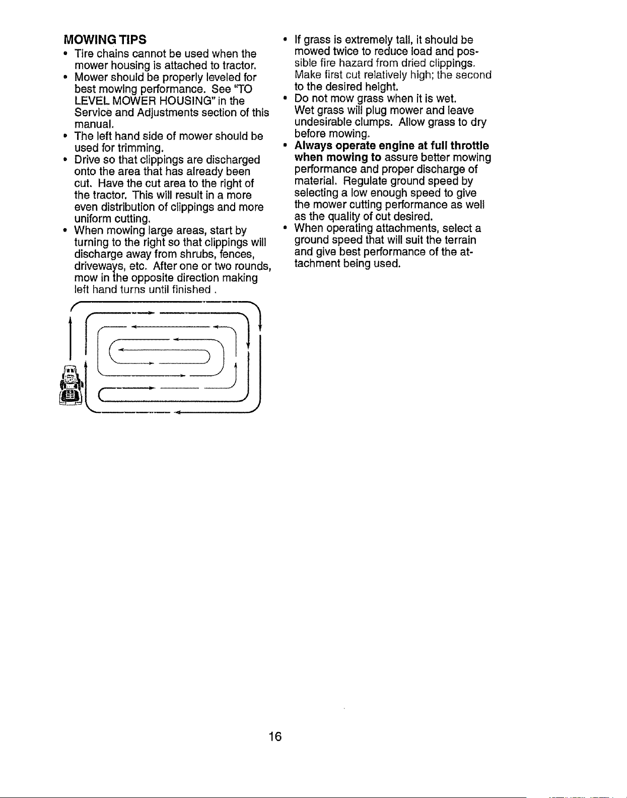
° When mowing large areas, start by
turning to the right so that clippings will
discharge away from shrubs, fences,
driveways, etc. After one or two rounds,
mow in the opposite direction making
left hand turns until finished •
f
]
JJ
• If grass is extremely tail, it should be
mowed twice to reduce load and pos*
sible fire hazard from dried clippings.
Make first cut relatively high; the second
to the desired height.
• Do not mow grass when it is wet.
Wet grass wilt plug mower and leave
undesirable clumps. Allow grass to dry
before mowing°
° Always operate engine at full throttle
when mowing to assure better mowing
performance and proper discharge of
material, Regulate ground speed by
selecting a low enough speed to give
the mower cutting performance as well
as the quality of cut desired.
• When operating attachments, select a
ground speed that will suit the terrain
and give best performance of the at-
tachment being used.
16
,, ,, ,,,,, ,............
MAINTENANCE RE_OR_EWRY EVERY
SCHEDULE EACH B 2s
USE HOURS HOURS
, , ,,, ,,,,,,,,,,,,,,,,,,,,,,,,,,,,,,,,
Check Brake Operation If If"
T Check Tire Pressure ........... ./V* V*
R ch_. operalor Presoa_p ,&,ROE System _. V
A Check for Loose Fasteners
v"
C ChacfdRepiace Mower Blades I_
EvE"_........._v'_.';......
50 100
HOURS HOURS
EVERY BEFORE
SEASON STORAGE
V'
T LubricationChart
0 Check Battery Level
R CieanBauer and Terminals .............. . ................ V*
C.heck Transaxte Cooling V _
Check Mower Levelness
Ch.e.£_...v:s.e!!_........
Check Englne eli Level V _ V e
Change Engine Of! (with oil _ter) ....
Change Engine eli (wltheu! ell tiltel Ik#'l,e
E CIean Air Filter I_=
G cfean Air Screen ............... I_
I Inspect Muffler/Spark Arrester
N Replace OilFiller (if equipp.e.d) .
E clean Englne Coolin 9 Fins
Re,face Spark Plug
Replace Air Filter Paper Cadrtdge,,
Replace Fuel Filter
! - Change mote often when operating under a heavy load or
In high ambient temperatures
2 - Service more often when operating in dirty or dusty condffions
I ............ ,
v'
v'
V'
.......V',._ v"
. V _ •
v'
V;,,_
v' v
v'.
v"
,,, ,,,,,,,,,,,,,, ,,,,,,,,,,,,,,,,,,,,,,,,,,,,,
3 -Repface blades more often when mow{ng In sandy soil
4 - Not requtred if equipped with matntanance4ree balte_'
GENERAL RECOMMENDATIONS
The warranty on this tractor does not
cover items that have been subjected to
operator abuse or negligence, To receive
ful! value from the warranty, operator
must maintain tractor as instructed in this
manual.
Some adjustments will need to be made
periodically to properly maintain your
tractor,
At least once a season, check to see if
you should make any of the adjustments
described in the Service and Adjustments
section of this manual
• At least once a year you should replace
the spark plug, clean or replace air filter,
and check blades and belts for wear.
A new spark plug and clean air filter
assure proper air-fuel mixture and help
your engine run better and last longer.
BEFORE EACH USE
I. Check engine oil level.
2. Check brake operation,
3. Check tire pressure,
4, Check operator presence and
ROE systems for proper operation,
5_ Check for loose fasteners.
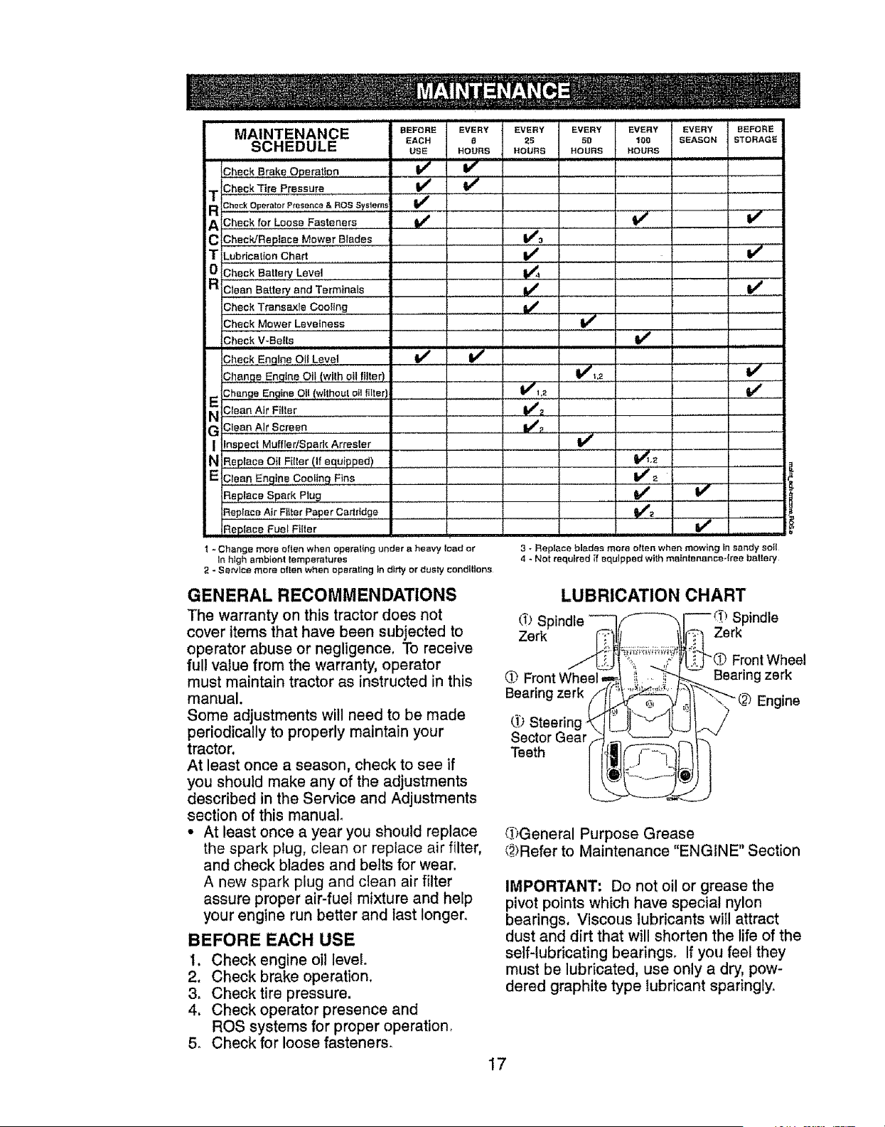
LUBRICATION CHART
d) Spindle
Zerk Zerk
d_')Front Wheel ,,
Bearing zerk
Sector Gear
Teeth
Front Wheel
Bearing zerk
-_-') Engine
_General Purpose Grease
(_)Refer to Maintenance "ENGINE" Section
IMPORTANT: Do not oil or grease the
pivot points which have special nylon
bearings. Viscous lubricants will attract
dust and dirt that will shorten the life of the
self-lubricating bearings. If you feel they
must be lubricated, use only a dry, pow-
dered graphite type lubricant sparingly.
17
TRACTOR
Always observe safety rules when per-
forming any maintenance.
BRAKE OPERATION
if tractor requires more than five (5) feet to
stop at highest speed in highest gear on a
level, dry concrete or paved surface, then
brake must be serviced. (See "TO CHECK
BRAKE" in the Service and Adjustments
section of this manual).
TIRES
, Maintain proper air pressure in all tires
(See PSI on tires)°
° Keep tires free of gasoline, oil, or insect
control chemicals which can harm rubber.
° Avoid stumps, stones, deep ruts, sharp
objects and other hazards that may
cause tire damage.
NOTE: To seal tire punctures and prevent
fiat tires due to slow leaks, tire sealant
may be purchased from your local parts
dealer, Tire sealant also prevents tire dry
rot and corrosion.
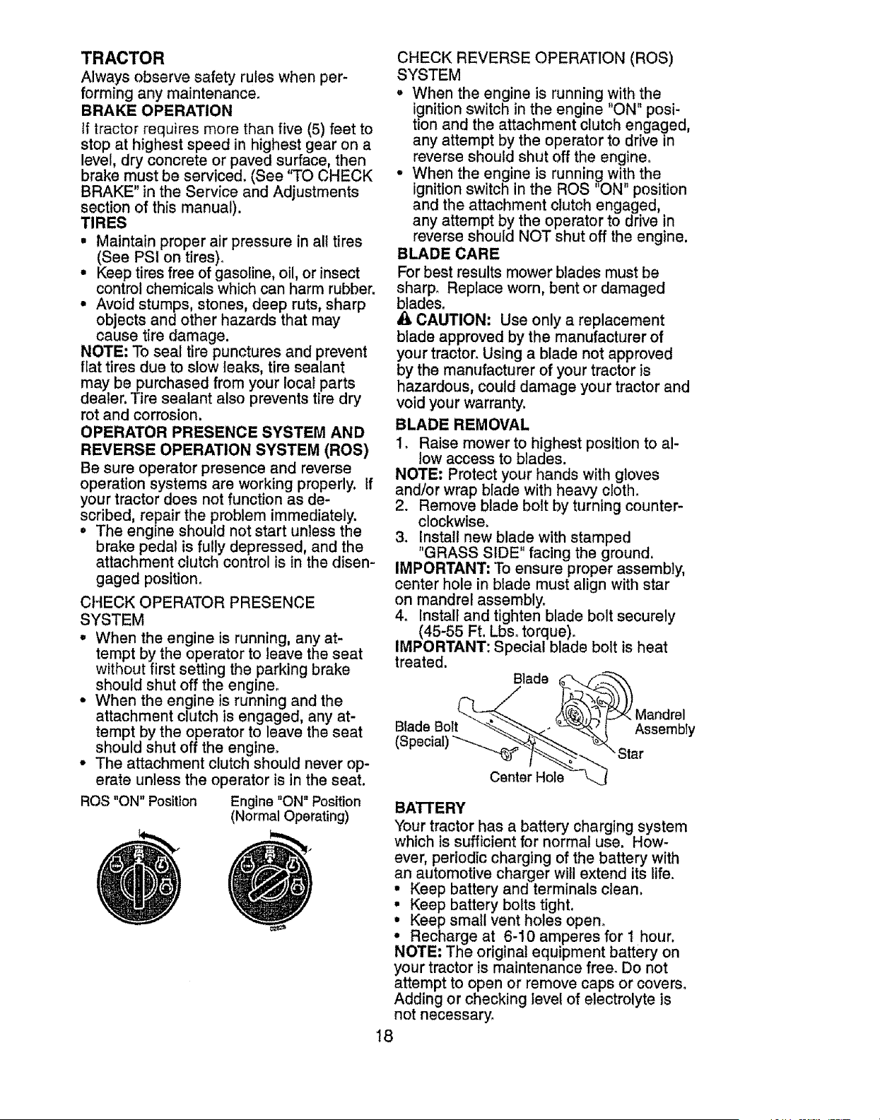
OPERATOR PRESENCE SYSTEM AND
REVERSE OPERATION SYSTEM (ROS)
Be sure operator presence and reverse
operation systems are working properly. If
your tractor does not function as de-
scribed, repair the problem immediately.
• The engine should not start unless the
brake pedal is fully depressed, and the
attachment clutch control is in the disen-
gaged position.
CHECK OPERATOR PRESENCE
SYSTEM
• When the engine is running, any at-
tempt by the operator to leave the seat
without first setting the parking brake
should shut off the engine.
• When the engine is running and the
attachment clutch is engaged, any at-
tempt by the operator to leave the seat
should shut off the engine.
° The attachment clutch should never op-
erate unless the operator is in the seat.
ROS "ON" Position Engine "ON" Position
(Normal Operating)
CHECK REVERSE OPERATION (ROS)
SYSTEM
° When the engine is running with the
ignition switch in the engine "ON" posi-
tion and the attachment clutch engaged,
any attempt by the operator to drive in
reverse should shut off the engine.
• When the engine is running with the
ignition switch in the ROS "ON" position
and the attachment clutch engaged,
any attempt by the operator to drive in
reverse should NOT shut off the engine.
BLADE CARE
For best results mower blades must be
sharp_ Replace worn, bent or damaged
blades.
_, CAUTION: Use only a replacement
blade approved by the manufacturer of
your tractor. Using a blade not approved
by the manufacturer of your tractor is
hazardous, could damage your tractor and
void your warranty.
BLADE REMOVAL
1_ Raise mower to highest position to a!-
low access to blades.
NOTE: Protect your hands with gloves
and/or wrap blade with heavy cloth.
2. Remove blade bolt by turning counter-
clockwise.
3. I,nstall new blade with stamped
'GRASS SIDE" facing the ground.
IMPORTANT: To ensure proper assembly,
center hole in blade must align with star
on mandrel assembly.
4. Install and tighten blade bolt securely
(45-55 Ft. Lbs. torque).
IMPORTANT: Special blade bolt is heat
treated.
Blade
Blade Bolt Assembly
Center Hole
BATrERY
Your tractor has a battery charging system
which is sufficient for normal use. How-
ever, periodic charging of the battery with
an automotive charger will extend =tslife.
° Keep battery and terminals clean,
° Keep battery bolts tight.
, Keep small vent holes open.
° Recharge at 6-10 amperes for t hour,
NOTE: The original equipment battery on
your tractor is maintenance free. Do not
attempt to open or remove caps or covers.
Adding or checking level of electrolyte is
not necessary.
!8
TOCLEANBATTERYANDTERMINALS
Corrosionanddirt on the batteryandtermi-
nalscan causethebatteryto "leak"power.
1_ DisconnectBLACKbatterycablefirst
then RED batterycableand remove
batteryfromtractor,
2, Rinsethe batterywith plainwater and
dry.
3, Cleanterminalsandbatterycableends
with wirebrushuntilbright.
4o Coatterminalswith greaseor petro-
lelJmjelly.
5. Reinstallbattery(See"REPLACING
BATTERY"in the SERVICEANDAD-
JUSTMENTSsectionof this manual).
TRANSAXLE COOLING
The transmission fan and cooling fins
should be kept clean to assure proper
cooling,
Do not attempt to clean fan or transmis-
sion while engine is running or while the
transmission is hot, "fb prevent possible
damage to seals, do not use high pressure
water or steam to clean transaxle.
° Inspect cooling fan to be sure fan blades
are intact and clean.
• Inspect cooling fins for dirt, grass clip-
pings and other materials. To prevent
damage to seals, do not use com-
pressed air or high pressure sprayer to
clean cooling fins.
TRANSAXLE PUMP FLUID
The transaxle was sealed at the factory
and fluid maintenance is not required for
the life of the transaxle. Should the trans-
axle ever leak or require servicing, contact
your nearest Sears or other qualified
service center,
V-BELTS
Check V-belts for deterioration and wear
after 100 hours of operation and replace
if necessary. The belts are not adjustable.
Replace belts if they begin to slip from
wear,
ENGINE
LUBRICATION
Only use high quality detergent oil rated
with API service classification SG-SL
Select the oil's SAE viscosity grade
according to your expected operating
temperature,
8AE VISCOSITY GRADES
Change the oil after every 50 hours of op-
eration or at least once a year if the tractor
is not used for 50 hours in one year,
Check the crankcase oil level before start-
ing the engine and after each eight (8)
hours of operation,
TO CHANGE ENGINE OIL
Determine temperature range expected
before oll change, All oil must meet API
service classification SG-SL
• Be sure tractor is on level surface°
, Oil will drain more freely when warm.
• Catch oil in a suitable container.
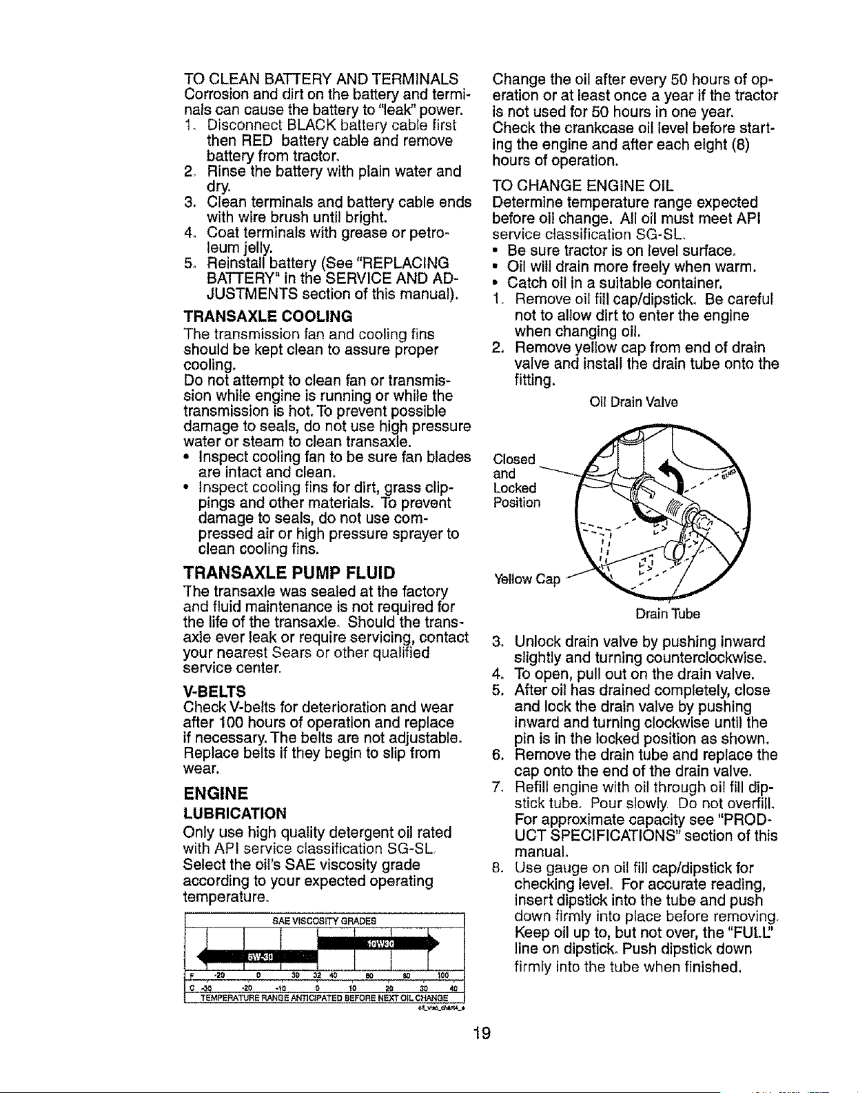
1. Remove oil fill cap/dipstick, Be careful
not to allow dirt to enter the engine
when changing oil
2. Remove yeflow cap from end of drain
valve and install the drain tube onto the
fitting.
Oil Drain Valve
Closed
and
Locked
Position
Yellow Cap
Drain Tube
& Unlock drain valve by pushing inward
slightly and turning counterclockwise.
4. To open, pull out on the drain valve.
5, After oil has drained completely, close
and lock the drain valve by pushing
inward and turning clockwise until the
pin is in the locked position as shown.
6. Remove the drain tube and replace the
cap onto the end of the drain valve.
7. Refill engine with oil through oil fill dip-
stick tube_ Pour slowly Do not overfill
For approximate capacity see "PROD-
UCT SPECIFICATIONS" section of this
manual
8, Use gauge on oil fill cap/dipstick for
checking level° For accurate reading,
insert dipstick into the tube and push
down firmly into place before removing,
Keep oil up to, but not over, the "FULU'
line on dipstick. Push dipstick down
firmly into the tube when finished.
19
ENGINE OIL FILTER
Replace the engine oil filter every season
or every other oil change if the tractor is
used more than 100 hours in one year.
AIR FILTER
Your engine will not run properly using
a dirty air filter. Service paper cartridge
every two months or every 25 hours of
operation, whichever occurs first,
Service paper cartridge more often under
dusty conditions.
Replace the paper cartridge annually, or
after every 100 hours of operation.
TO SERVICE CARTRIDGE
• Replace a dirty, bent, or damaged car-
tridge. Handle new cartridge carefully;
do not use if the rubber seal is dam-
aged.
NOTE: Do not wash the paper cartridge
or use pressurized air, as this will damage
the cartridge.
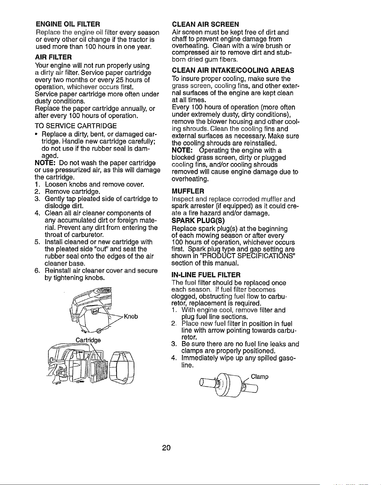
1. Loosen knobs and remove cover.
2. Remove cartridge.
3. Gently tap pleated side of cartridge to
dislodge dirt,
4. Clean all air cleaner components of
any accumulated dirt or foreign mate-
daL Prevent any dirt from entering the
throat of carburetor.
5. Install cleaned or new cartridge with
the pleated side "out" and seat the
rubber seal onto the edges of the air
cleaner base.
6. Reinstall air cleaner cover and secure
by tightening knobs,
__ .Knob
Cartridge
CLEAN AIR SCREEN
Air screen must be kept free of dirt and
chaff to prevent engine damage from
overheating, Clean with a wire brush or
compressed air to remove dirt and stub-
born dried gum fibers.
CLEAN AIR INTAKE/COOLING AREAS
To insure proper cooling, make sure the
grass screen, cooling fins, and other exter-
nal surfaces of the engine are kept clean
at all times.
Every t00 hours of operation (more often
under extremely dusty, dirty conditions),
remove the blower housing and other cool-
ing shrouds, Clean the cooling fins and
external surfaces as necessary. Make sure
the cooling shrouds are reinstalled.
NOTE: Operating the engine with a
blocked grass screen, dirty or plugged
cooling fins, and/or cooling shrouds
removed will cause engine damage due to
overheating,
MUFFLER
Inspect and replace corroded muffler and
spark arrester (if equipped) as it could cre-
ate a fire hazard and/or damage.
SPARK PLUG(S)
Replace spark plug(s) at the beginning
of each mowing season or after every
100 hours of operation, whichever occurs
first, Spark plug type and gap setting are
shown in "PRODUCT SPECIFICATIONS"
section of this manual,
IN-LINE FUEL FILTER
The fuel filter should be replaced once
each season If fuel filter becomes
clogged, obstructing fuel flow to carbu,-
retor, replacement is required.
1. With engine coo!, remove filter and
plug fuel line sections.
2. Place new fuel filter in position in fuel
line with arrow pointing towards carbu-
retor.
3. Be sure there are no fuel line leaks and
clamps are properly positioned.
4o Immediately wipe up any spilled gaso-
line.
amp
2O
CLEANING
• Clean engine, battery, seat, finish, etc.
of al! foreign matter.
• Keep finished surfaces and wheels free
of all gasoline, oil, etc.
• Protect painted surfaces with auto-
motive type wax.
We do not recommend using a garden
hose or pressure washer to clean your
tractor unless the engine and transmis-
sion are covered to keep water out. Water
in engine or transmission will shorten the
useful life of your tractor, Use compressed
air or a leaf blower to remove grass,
leaves and trash from tractor and mower.
WARNING: TO AVOID SERIOUS INJURY, BEFORE PERFORMING ANY SER-
VICE OR ADJUSTMENTS:,&
1.
2,
3.
4,
5.
Depress brake pedal fully and set parking b,[akeo
Place attachment clutch in DISENGAGED position,
Turn ignition key to "STOP" and remove key.
Make sure the blades and all moving parts have completely stopped.
Disconnect spark plug wire from spark plug and place wire where it cannot
come in contact with plug,
TRACTOR
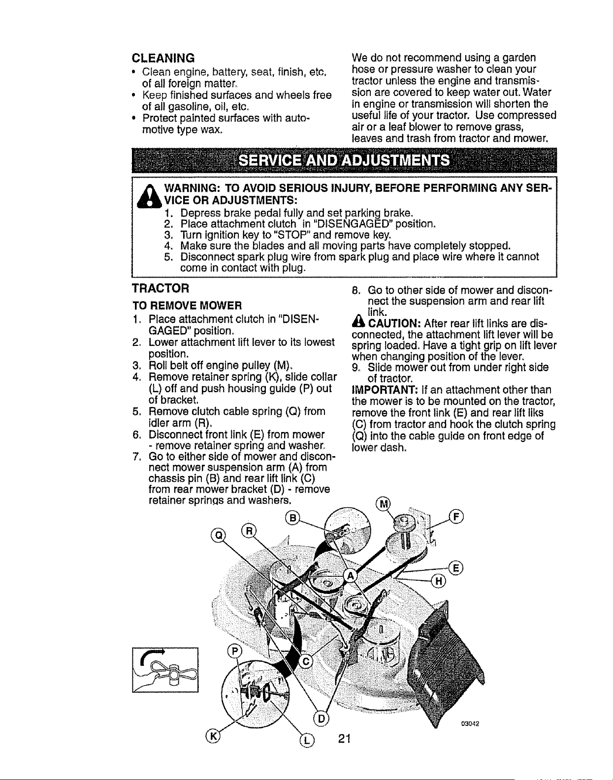
TO REMOVE MOWER
1_ Place attachment clutch in"DISEN-
GAGED" position.
2o Lower attachment lift lever to its lowest
position.
3. Roll belt off engine pulley (M).
4. Remove retainer spring (K), slide collar
(L) off and push housing guide (P) out
of bracket.
5. Remove clutch cable spring (Q) from
idler arm (R).
6. Disconnect front link (E) from mower
- remove retainer spring and washer°
7. Go to either side of mower and discon-
nect mower suspension arm (A) from
chassis pin (B) and rear lift link (C)
from rear mower bracket (D) - remove
retainer sprinqs and washers.
8, Go to other side of mower and discon-
nect the suspension arm and rear lift
link.
CAUTION: After rear lift links are dis-
connected, the attachment lift lever will be
spring Ioaded, Have a tight grip on lift lever
when changing position of the lever,
9o Slide mower out from under right side
of tractor.
IMPORTANT: If an attachment other than
the mower is to be mounted on the tractor,
remove the front link (E) and rear lift liks
(C) from tractor and hook the clutch spring
(Q) into the cable guide on front edge of
lower dash,
21
03042

TO INSTALL MOWER
Be sure tractor is on level surface and
engage parking brake,
1. Lower attachment lift lever to it's lowest
position.
_. CAUTION: Lift lever is spring loaded.
Have a tight grip on lift lever, lower it
slowly and engage in lowest position.
NOTE: Be sure mower side suspension
arms (A) are pointing forward before slid-
ing mower under tractor.
2o Slide mower under tractor until it Is
centered under tractor.
3. ATTACH MOWER SIDE SUSPENSION
ARMS (A) TO CHASSIS - Position hole
in arm over pin (B) on outside of tractor
chassis and secure with washer and
retainer spring.
4. Repeat on opposite side of tractor,
7. ATT_,CH FRONT LINK (E) - Work from
left side of tractor. Insert rod end of link
assembly through front hole in tractor
front suspension bracket (F).
8_ Insert end of link (E) into hole in front
mower bracket (H) and secure with
washer and retainer spring (J).
5, ATTACH REAR LIFT LINKS (C) - Lift
rear corner of mower and position
slot in link assembly over pin on rear
mower bracket (D) and secure with
washer and retainer spring°
6, Repeat on opposite side of tractor,
9. Push clutch cable housing guide (P)
into bracket, slide collar (L) onto guide
and secure with retainer spring (K).
10_Hook end of clutch cable spring (Q)
into hole in idler arm (R)_
22
03042
11. Install belt onto engine clutch pulley (M).
IMPORTANT: Check belt for proper rout-
ing in all mower pulley grooves.
12_Raise attachment lift lever to highest
position.
13. If necessary, adjust gauge wheels be-
fore operating mower as shown in the
Operation section of this manual.
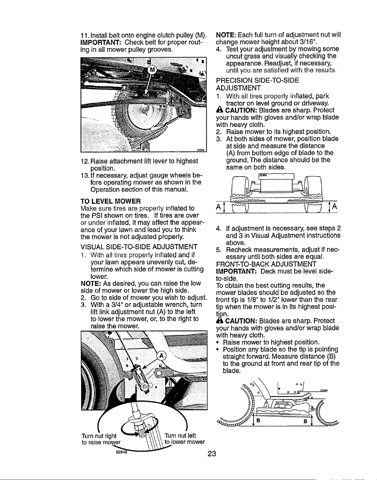
TO LEVEL MOWER
Make sure tires are properly inflated to
the PSI shown on tires. If tires are over
or under inflated, it may affect the appear-
ance of your lawn and lead you to think
the mower is not adjusted properly.
VISUAL SIDE-TO-SIDE ADJUSTMENT
1. With al! tires properly inflated and if
your lawn appears unevenly cut, de-
termine which side of mower is cutting
lower.
NOTE: As desired, you can raise the low
side of mower or lower the high side,
2. Go to side of mower you wish to adjust.
3. With a 3/4" or adjustable wrench, turn
lift link adjustment nut (A) to the left
to lower the mower, or, to the right to
raise the mower.
Turn nut dght
to raise mower
Turn nut left
to lower mower
NOTE: Each full turn of adjustment nut will
change mower height about 3/16".
4. Test your adjustment by mowing some
uncut grass and visually checking the
appearance. Readjust, if necessary,
untit you are satisfied with the results.
PRECISION SIDE-TO-SIDE
ADJUSTMENT
1. With all tires properly inflated, park
tractor on level ground or driveway.
CAUTION; Blades are sharp. Protect
your hands with gloves and/or wrap blade
with heavy cloth.
2. Raise mower to its highest position.
3. At both sides of mower, position blade
at side and measure the distance
(A) from bottom edge of blade to the
ground. The distance should be the
same on both sides.
4. If adjustment is necessary, see steps 2
and 3 in Visual Adjustment instructions
above.
5. Recheck measurements, adjust if nec-
essary until both sides are equal.
FRONTTO-BACK ADJUSTMENT
IMPORTANT: Deck must be level side-
to-side.
To obtain the best cutting results, the
mower blades should be adjusted so the
front tip is 1!8" to 1/2" lower than the rear
tip when the mower is in its highest posi-
CAUTION: Blades are sharp. Protect
your hands with gloves and/or wrap blade
with heavy cloth.
• Raise mower to highest position.
• Position any blade so the tip is pointing
straight forward, Measure distance (B)
to the ground at front and rear tip of the
blade.
I. oo°f o.
23
° If front tip of blade is not 1/8" to 1/2"
lower than the rear tip, go to the front of
tractor.
• With an 11/t6" or adjustable wrench,
loosen jam nut A several turns to clear
adjustment nut B.
• With a 3/4" or adjustable wrench, turn
front link adjustment nut (B) clockwise
(tighten) to raise the front of mower, or,
counterclockwise (loosen) to lower the
front mower.
NOTE: Each full turn of the adjustment
nut will change mower height about 1/8'L
° Recheck measurements, adjust if nec-
essary until front tip of blade is t/8" to
1/2" lower than the rear tipo
• Hold adjustment nut in position with
wrench and tighten jam nut securely
against adjustment nut,
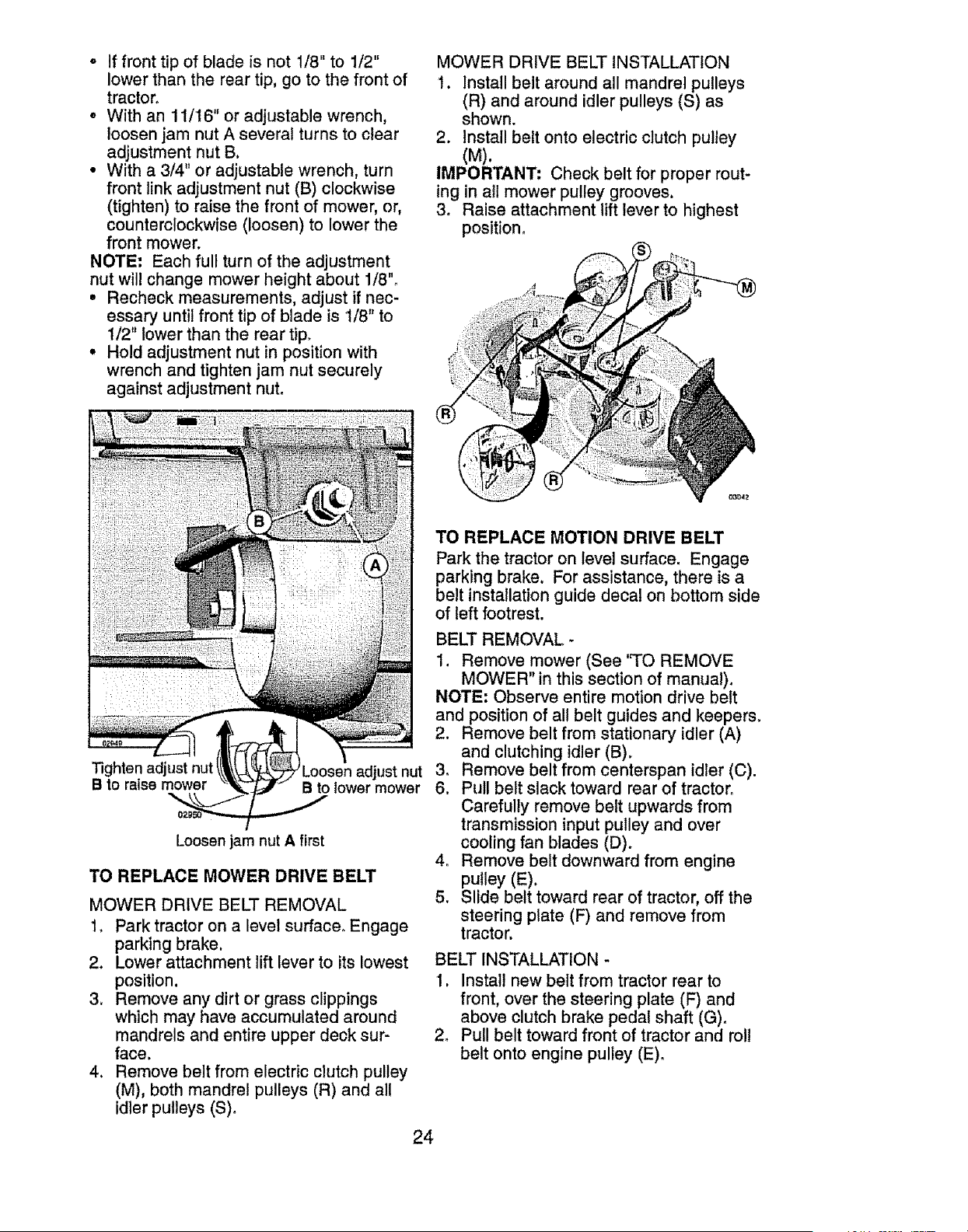
MOWER DRIVE BELT INSTALLATION
1. Install belt around all mandrel pulleys
(R) and around idler pulleys (S) as
shown,
2. Install belt onto electric clutch pulley
(M).
IMPORTANT: Check belt for proper rout-
ing in all mower pulley grooves,
3. Raise attachment lift lever to highest
position.
Tighten adjust nut
B to raise mower
Loosen adjust nut
B to lower mower
Loosen jam nut A first
TO REPLACE MOWER DRIVE BELT
MOWER DRIVE BELT REMOVAL
1, Park tractor on a level surface° Engage
parking brake,
2. Lower attachment lift lever to its lowest
position.
3. Remove any dirt or grass clippings
which may have accumulated around
mandrels and entire upper deck sur-
face.
4. Remove belt from electric clutch pulley
(M), both mandrel pulleys (R) and all
idler pulleys (S).
TO REPLACE MOTION DRIVE BELT
Park the tractor on level surface_ Engage
parking brake. For assistance, there is a
belt installation guide decal on bottom side
of left footrest.
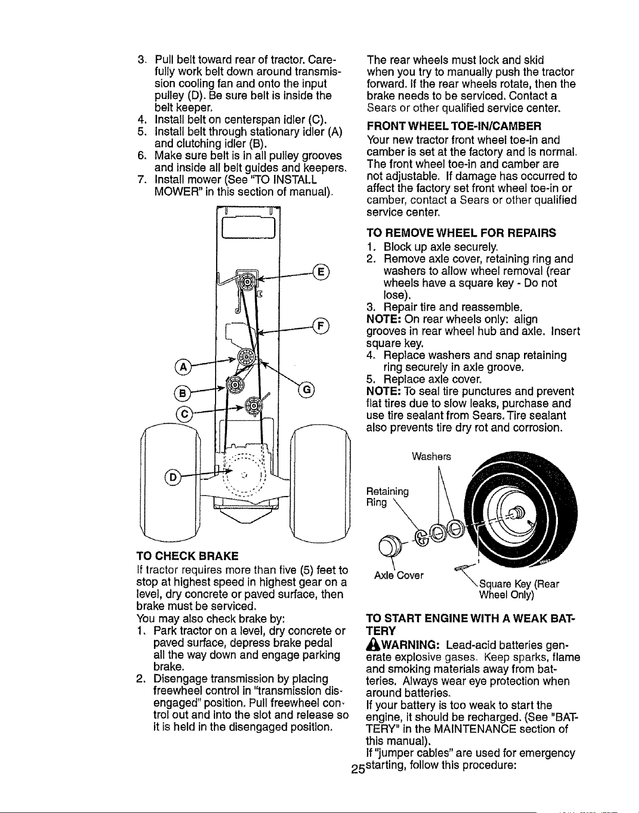
BELT REMOVAL -
1. Remove mower (See 'q'O REMOVE
MOWER" in this section of manual).
NOTE: Observe entire motion drive belt
and position of al! belt guides and keepers,
2. Remove belt from stationary idler (A)
and clutching idler (B).
3, Remove belt from centerspan idler (C).
6. Pull belt slack toward rear of tractor.
Carefully remove belt upwards from
transmission input pulley and over
cooling fan blades (D).
4. Remove belt downward from engine
pulley (E).
5. Slide belt toward rear of tractor, off the
steering plate (F) and remove from
tractor,
BELT INSTALLATION -
1, Install new belt from tractor rear to
front, over the steering plate (F) and
above clutch brake pedal shaft (G).
2, Pull belt toward front of tractor and rol!
belt onto engine pulley (E),
24
3. Pull belt toward rear of tractor, Care-
fully work belt down around transmis-
sion cooling fan and onto the input
pulley (D). Be sure belt is inside the
belt keeper.
4, Install belt on centerspan idler (C).
5. Install belt through stationary idler (A)
and clutching idler (B),
6. Make sure belt is in all pulley grooves
and inside all belt guides and keepers.
7. Install mower (See "TO INSTALL
MOWER" in this section of manual).
'3"
TO CHECK BRAKE
t
If tractor requires more than five (5) feet to
stop at highest speed in highest gear on a
level, dry concrete or paved surface, then
brake must be serviced.
You may also check brake by:
1, Park tractor on a level, dry concrete or
paved surface, depress brake pedal
all the way down and engage parking
brake.
2. Disengage transmission by placing
freewheel control in "transmission dis-
engaged" position. Pull freewheel corn
trol out and into the slot and release so
it is held in the disengaged position.
The rear wheels must lock and skid
when you try to manually push the tractor
forward, tf the rear wheels rotate, then the
brake needs to be serviced. Contact a
Sears or other qualified service centers
FRONT WHEEL TOE-IN/CAMBER
Your new tractor front wheel toe-in and
camber is set at the factory and is normal.
The front wheel toe-in and camber are
not adjustable. If damage has occurred to
affect the factory set front wheel toe-in or
camber, contact a Sears or ether qualified
service center°
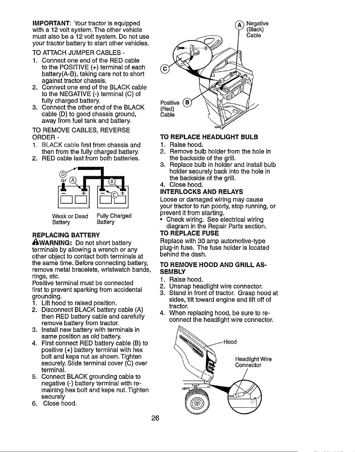
TO REMOVE WHEEL FOR REPAIRS
I. Block up axle securely.
2. Remove axle cover, retaining ring and
washers to allow wheel removal (rear
wheels have a square key - Do not
lose),
3, Repair tire and reassemble.
NOTE; On rear wheels only: align
grooves in rear wheel hub and axle. Insert
square key,
4. Replace washers and snap retaining
ring securely in axle groove,
5. Replace axle cover,
NOTE; To seal tire punctures and prevent
flat tires due to slow leaks, purchase and
use tire sealant from Sears. Tire sealant
also prevents tire dry rot and corrosion.
Washers
Retaining
Ring
Axle Cover
t
'_Square Key (Rear
Wheel Only)
TO START ENGINE WITH A WEAK BAT-
TERY
_WARNING: Lead-acid batteries gen-
erate explosive gases° Keep sparks, flame
and smoking materials away from bat-
teries. Always wear eye protection when
around batteries.
If your battery is too weak to start the
engine, it should be recharged. (See "BAT-
TERY" in the MAINTENANCE section of
this manual).
If "jumper cables"are used for emergency
25starting, follow this procedure:
IMPORTANT: Your tractor is equipped
with a 12 volt system° The other vehicle
must also be a t2 volt system. Do not use
your tractor battery to start other vehicles.
TO ATTACH JUMPER CABLES -
1, Connect one end of the RED cable
to the POSITIVE (+) terminal of each
battery(A-B), taking care not to short
against tractor chassis.
2. Connect one end of the BLACK cable
to the NEGATIVE (-) terminal (C) of
fully charged battery.
3. Connect the other end of the BLACK
cable (D) to good chassis ground,
away from fuel tank and battery_
TO REMOVE CABLES, REVERSE
ORDER -
1. BLACK cable first from chassis and
then from the fully charged battery.
2. RED cable last from both batteries.
Weak or Dead Fully Charged
Battery Battery
REPLACING BATTERY
_WARNING: Do not short battery
terminals by allowing a wrench or any
other object to contact both terminals at
the same time. Before connecting battery,
remove metal bracelets, wristwatch bands,
rings, etc,
Positive terminal must be connected
first to prevent sparking from accidental
grounding,
1. Lift hood to raised position.
2. Disconnect BLACK battery cable (A)
then RED battery cable and carefully
remove battery from tractor,
3. Install new battery with terminals in
same position as old battery.
4. First connect RED battery cable (B) to
positive (+) battery terminal with hex
bolt and keps nut as shown, Tighten
securely. Slide terminal cover (C) over
terminal°
5_ Connect BLACK grounding cable to
negative (-) battery terminal with re-
maining hex bolt and keps nut, Tighten
securely
6, Close hood,
(_ Negative
(Black)
Cable
Positive
(Red)
Cable
TO REPLACE HEADLIGHT BULB
1. Raise hood.
2. Remove bulb holder from the hole in
the backside of the grill.
3. Replace bulb in holder and install bulb
holder securely back into the hole in
the backside of the grill°
4. Close hood°
INTERLOCKS AND RELAYS
Loose or damaged wiring may cause
your tractor to run poorly, stop running, or
prevent it from starting.
, Check wiring, See electrical wiring
diagram in the Repair Parts section,
TO REPLACE FUSE
Replace with 30 amp automotive-type
plug-in fuse, The fuse holder is located
behind the dash,
TO REMOVE HOOD AND GRILL AS-
SEMBLY
1. Raise hood.
2. Unsnap headlight wire connector.
3, Stand in front of tractor. Grasp hood at
sides, tilt toward engine and lift off of
tractor.
4. When replacing hood, be sure to re..
connect the headlight wire connector.
\ , Head,grit rWire
26
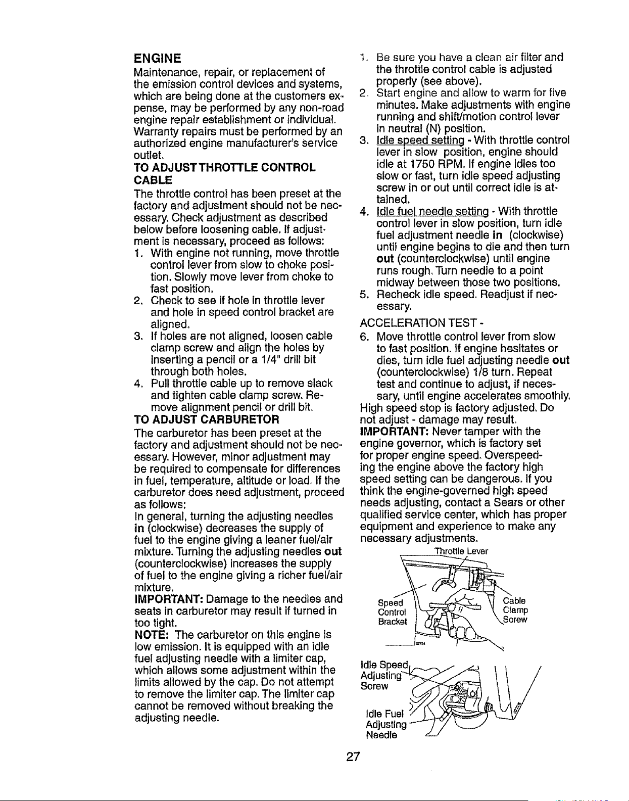
ENGINE
Maintenance, repair, or replacement of
the emission control devices and systems,
which are being done at the customers ex-
pense, may be performed by any non-road
engine repair establishment or individual,
Warranty repairs must be performed by an
authorized engine manufacturer's Service
outlet,
TO ADJUSTTHROTI'LE CONTROL
CABLE
The throttle control has been preset at the
factory and adjustment should not be nec-
essary. Check adjustment as described
below before loosening cable. If adjust,,
ment is necessary, proceed as follows:
I. With engine not running, move throttle
control lever from slow to choke posi-
tion. Slowly move lever from choke to
fast position,
2. Check to see if hole in throttle lever
and hole in speed control bracket are
aligned°
3, If holes are not aligned, loosen cable
clamp screw and align the holes by
inserting a pencil or a 1/4" drill bit
through both holes.
4, Pull throttle cable up to remove slack
and tighten cable clamp screw, Re-
move alignment pencil or drill bit.
TO ADJUST CARBURETOR
The carburetor has been preset at the
factory and adjustment should not be nec-
essary, However, minor adjustment may
be required to compensate for differences
in fuel, temperature, altitude or Ioad_ If the
carburetor does need adjustment, proceed
as follows:
In general, turning the adjusting needles
in (clockwise) decreases the supply of
fuel to the engine giving a leaner fue!/air
mixture, Turning the adjusting needles out
(counterclockwise) increases the supply
of fuel to the engine giving a richer fuel/air
mixture,
IMPORTANT; Damage to the needles and
seats in carburetor may result if turned in
too tight.
NOTE: The carburetor on this engine is
low emission. It is equipped with an idle
fuel adjusting needle with a limiter cap,
which allows some adjustment within the
limits allowed by the cap, Do not attempt
to remove the limiter cap. The limiter cap
cannot be removed without breaking the
adjusting needle,
t, Be sure you have a clean air filter and
the throttle control cable is adjusted
properly (see above),
2. Start engine and allow to warm for five
minutes, Make adjustments with engine
running and shift/motion control lever
in neutral (N) position.
3. Idle speed setting - With throttle control
lever in slow position, engine should
idle at 1750 RPM, If engine idles too
slow or fast, turn idle speed adjusting
screw in or out until correct idle is at-
tained.
4. Idle fuel needle setting - With throttle
control lever in slow position, turn idle
fuef adjustment needle in (clockwise)
until engine begins to die and then turn
out (counterclockwise) until engine
runs rough, Turn needle to a point
midway between those two positions,
5. Recheck idle speed, Readjust if nec-
essary.
ACCELERATION TEST -
6. Move throttle control lever from slow
to fast position. If engine hesitates or
dies, turn idle fuel adjusting needle out
(counterclockwise) 1/8 turn, Repeat
test and continue to adjust, if neces-
sary, until engine accelerates smoothly.
High speed stop is factory adjusted. Do
not adjust - damage may result.
IMPORTANT: Never tamper with the
engine governor, which is factory set
for proper engine speed, Overspeed-
ing the engine above the factory high
speed setting can be dangerous. If you
think the engine-governed high speed
needs adjusting, contact a Sears or other
qualified service center, which has proper
equipment and experience to make any
necessary adjustments_
Throttle Lever
Idle Speedt ._.v_ ._._ _ _ _ /
Adjusting-_ J
Screw .J ..4_<_
Idle Fuel )_/__
Adjusting ._r / 7 k...._
Needle z_./
27
Immediately prepare your tractor for stor-
age at the end of the season or if the trac-
_wAWillnot be used for 30 days or more°
RNING. Never store the tractor
with gasoline in the tank inside a building
where fumes may reach an open flame
or spark. Allow the engine to cool before
storing in any enclosure.
TRACTOR
When tractor is to be stored for a period
of time, clean it thoroughly, remove all dirt,
grease, leaves, etc. Store in a clean, dry
area.
1. Clean entire tractor (See "CLEANING"
in the Maintenance section of this
manual),
2. Inspect and replace belts, if necessary
(See belt replacement instructions in
the Service and Adjustments section of
this manual).
3. Lubricate as shown in the Maintenance
section of this manual.
4. Be sure that al! nuts, bolts and screws
are securely fastened. Inspect moving
parts for damage, breakage and wear.
Replace if necessary°
5. Touch up all rusted or chipped paint
surfaces; sand lightly before painting.
BATTERY
• Fully charge the battery for storage_
• After a period of time in storage, battery
may require recharging.
• To help prevent corrosion and power
leakage during long periods of storage,
battery cables should be disconnected
and battery cleaned thoroughly (see "TO
CLEAN BATTERY AND TERMINALS" in
the Maintenance section of this manual).
° After cleaning, leave cables discon-
nected and place cables where they
cannot come in contact with battery
terminals.
• If battery is removed from tractor for
storage, do not store battery directly on
concrete or damp surfaces.
ENGINE
FUEL SYSTEM
IMPORTANT: It is important to prevent
gum deposits from forming in essential
fuel system parts such as carburetor, fuel
hose, or tank during storage. Also, alcohol
blended fuels (called gasohol or using
ethanol or methanol) can attract moisture
which leads to separation and formation of
acids during storage. Acidic gas can dam-
age the fuel system of an engine while in
storage.
, Empty the fuel tank by starting the en-
gine and letting it run until the fue! lines
and carburetor are empty.
° Never use engine or carburetor cleaner
products in the fuel tank or permanent
damage may occur.
° Use fresh fuel next season,
NOTE: Fuel stabilizer is an acceptable
alternative in minimizing the formation of
fuel gum deposits during storage. Add
stabilizer to gasoline in fuel tank or stor-
age container. Always follow the mix ratio
found on stabilizer container. Run engine
at least 10 minutes after adding stabilizer
to allow the stabilizer to reach the carbure-
tor. Do not empty the gas tank and carbu-
retor if using fuel stabilizer.
ENGINE OIL
Drain oil (with engine warm) and replace
with clean engine oil (See "ENGINE" in
the Maintenance section of this manual).
CYLINDER(S)
1. Remove spark plug(s).
2. Pour one ounce of oil through spark
plug hole(s) into cylinder(s).
3. Turn ignition key to start position for a
few seconds to distribute oil,
4. Replace with new spark plug(s),
OTHER
° Do not store gasoline from one season
to another.
• Replace your gasoline can if your can
starts to rust. Rust and/or dirt in your
gasoline will cause problems.
• If possible, store your tractor indoors
and cover it to give protection from dust
and dirt.
° Cover your tractor with a suitable pro-
tective cover that does not retain mois-
ture. Do not use plastic. Plastic cannot
breathe which allows condensation to
form and will cause your tractor to rust.
IMPORTANT: Never cover tractor while
engine and exhaust areas are still warm.
28
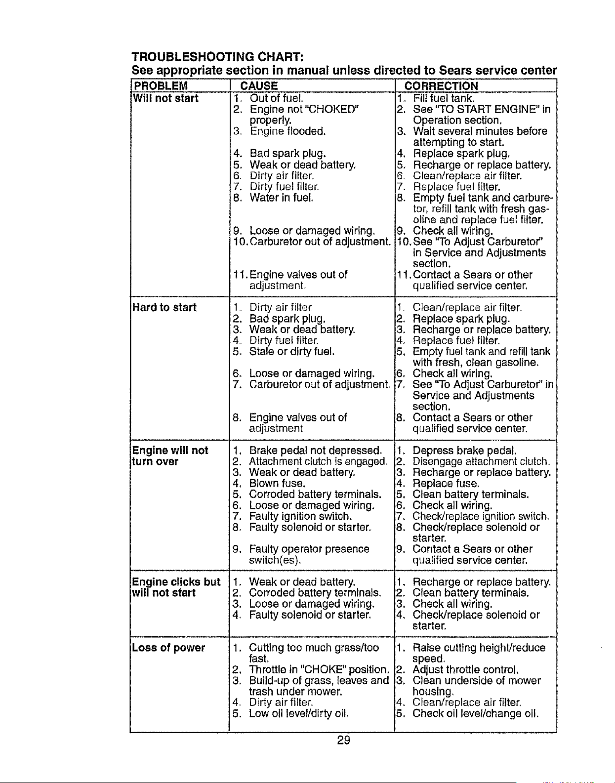
TROUBLESHOOTING CHART:
See appropriate section in manual unless directed to Sears service center
PROBLEM CAUSE CORRECTION
Will not start 1, OUt Of fuel
2, Engine not"CHOKED"
properly.
3, Engine flooded,
4, Bad spark plug,
5_ Weak or dead battery,
6, Dirty air filter,
7, Dirty fuel filter,
8, Water in fuel
1. Filf fuel tank.
2. See "TO START ENGINE" in
Operation section.
3. Wait several minutes before
attempting to start.
4, Replace spark plug.
5, Recharge or replace battery.
6. Clean/replace air filter.
7_ Replace fuel filter.
8, Empty fuel tank and carbure-
tor, refill tank with fresh gas-
oline and replace fuel filter.
Hard to start
Engine will not
turn over
Engine clicks but
will not start
Loss of power
9. Loose or damaged wiring.
10. Carburetor out of adjustment,
11, Engine valves out of
adjustment
1o Dirty air filter,
2, Bad spark plug.
3. Weak or dead battery.
4. Dirty fuel filter_
5_ Stale or dirty fue!.
6. Loose or damaged wiring.
7. Carburetor out of adjustmenL
8. Engine valves out of
adjustment
1. Brake pedal not depressed.
2. Attachment clutch is engaged°
3, Weak or dead battery,
4, Blown fuse,
5. Corroded battery terminals.
6. Loose or damaged wiring.
7. Faulty ignitionswitch,
8. Faulty solenoid or starter.
g_
Faulty operator presence
switch(es).
9. Check all wiring.
10. See "To Adjust Carburetor"
in Service and Adjustments
section.
11, Contact a Sears or other
qualified service center,
1o Clean/replace airfilter,
2, Replace spark plug,
3. Recharge or replace battery.
4o Replace fuel filter,
5. Empty fuel tank and refill tank
with fresh, clean gasoline.
6. Check all wiring,
7. See "To Adjust Carburetor'' in
Service and Adjustments
section.
8. Contact a Sears or other
qualified service center.
1. Depress brake pedal,
2. Disengage attachment clutch,
3_ Recharge or replace battery,
4. Replace fuse,
5. Clean battery terminals,
6. Check all wiring.
7, Check/replace ignition switch,
8, Check/replace solenoid or
starter.
9. Contact a Sears or other
qualified service center.
1_ Weak or dead battery,
2. Corroded battery terminals,
3. Loose or damaged wiring.
4_ Faulty solenoid or starter.
1. Cutting too much grass/too
fasL
2. Throttle in "CHOKE" position.
3. Build-up of grass, leaves and
trash under mower.
4. Dirty air filter.
5. Low oil leve!/dirty oil.
29
1, Recharge or replace battery,
2, Clean battery terminals,
3o Check all wiring.
4, Check/replace solenoid or
starter,
1. Raise cutting height/reduce
speed_
2_ Adjust throttle control,
3. Clean underside of mower
housing.
4. Clean/replace air filter,
5o Check oil level/change oil.
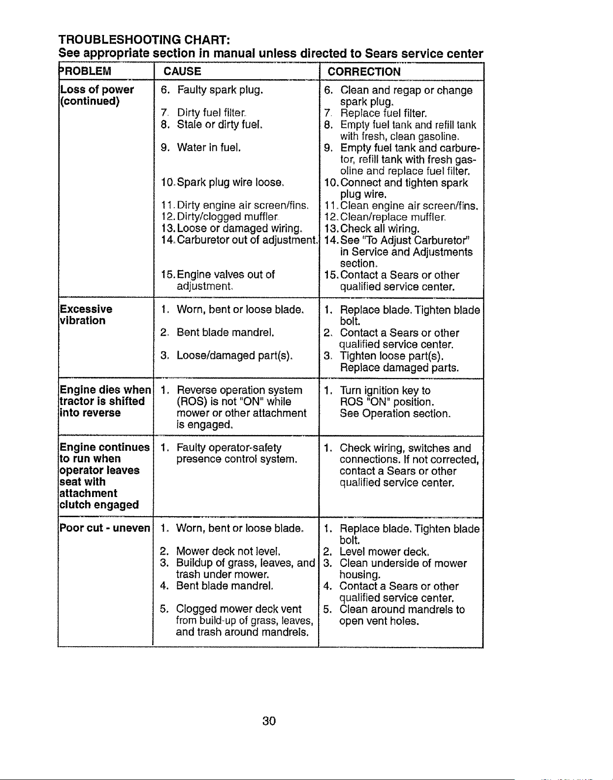
TROUBLESHOOTING CHART:
See appropriate section in manual unless directed to Sears service center
=ROBLEM CORRECTION
Loss of power
continued)
Excessive
vibration
Engine dies when
tractor is shifted
into reverse
Engine continues
to run when
operator leaves
seat with
attachment
clutch engaged
Poor cut - uneven
CAUSE
6. Faulty spark plug.
7. Dirty fue! filter,
8. Stale or dirty fuel
9. Water in fuel.
10. Spark plug wire loose.
1!. Dirty engine air screen/fins.
12. Dirty/clogged muffler
13. Loose or damaged wiring.
14. Carburetor out of adjustment.
15. Engine valves out of
adjustment.
1. Worn, bent or loose blade.
2_ Bent blade mandrel.
3. Loose/damaged part(s)o
1,
Reverse operation system
(ROS) is not "ON" while
mower or other attachment
is engaged.
1. Faulty operator-safety
presence control system.
2.
3.
4.
5.
Worn, bent or loose blade.
Mower deck not level.
Buildup of grass, leaves, and
trash under mower.
Bent blade mandrel.
Clogged mower deck vent
from build-up of grass, leaves,
and trash around mandrels.
6. Clean and regap or change
. spark plug,
Replace fuel filter_
8. Empty fuel tank and refill tank
with fresh, clean gasoline°
9. Empty fuel tank and carbure-
tor, refill tank with fresh gas-
oline and replace fuel filter,
10. Connect and tighten spark
plug wire,
11. Clean engine air screen/fins.
12, Clean/replace muffler,
13. Check all wiring.
14, See 'q'o Adjust Carburetor"
in Service and Adjustments
section,
15, Contact a Sears or other
qualified service center.
1. Replace blade. Tighten blade
bolt.
2. Contact a Sears or other
qualified service center.
3_ Tighten loose part(s).
Replace damaged parts.
1. Turn ignition key to
ROS "ON" position.
See Operation section.
Check wiring, switches and
connections. If not corrected,
contact a Sears or other
qualified service center,
1. Replace blade. Tighten blade
bolt.
2. Level mower deck.
3. Clean underside of mower
housing.
4. Contact a Sears or other
qualified service center.
5. Clean around mandrels to
open vent holes.
3O
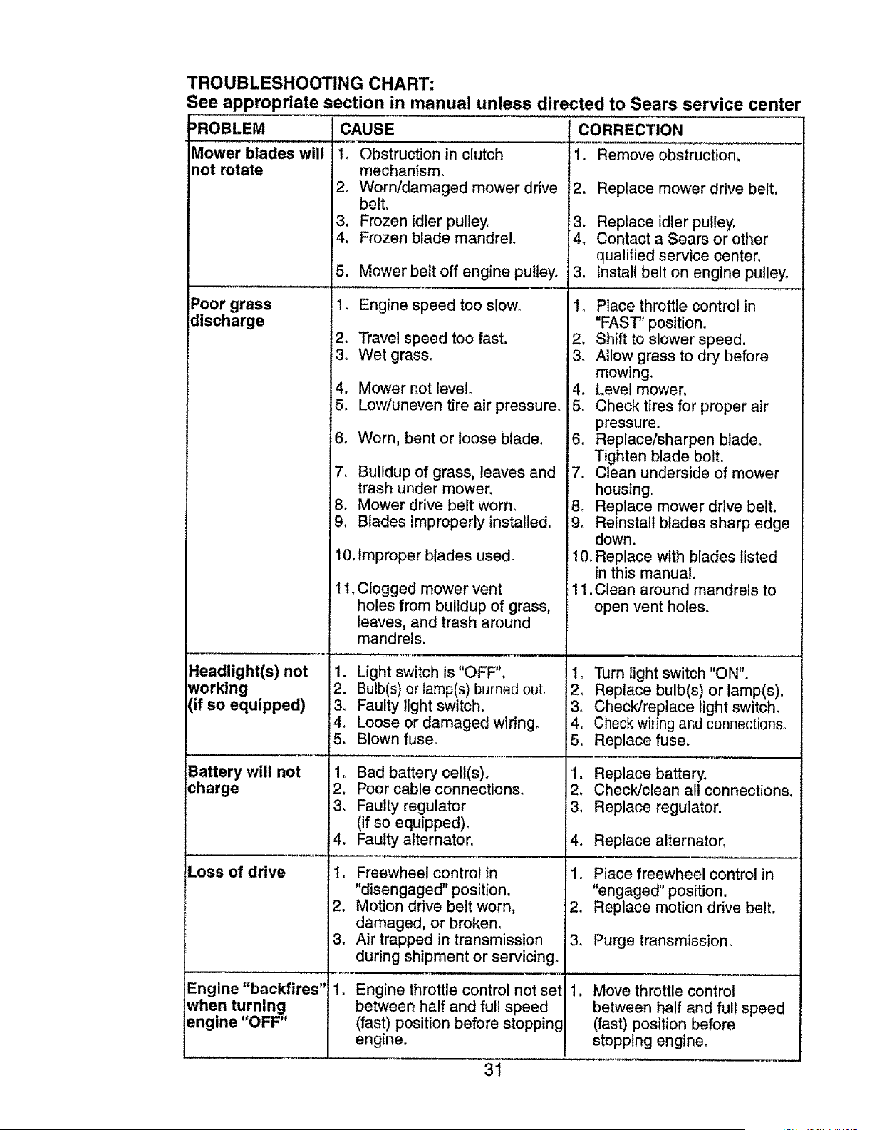
TROUBLESHOOTING CHART:
See appropriate section in manual unless directed to Sears service center
=ROBLEM
Mower blades will
not rotate
Poor grass
discharge
Headlight(s) not
working
(if so equipped)
Battery will not
charge
CAUSE
I_ Obstruction in chJtch
mechanism,
2. Worn/damaged mower drive
belt,
3. Frozen idler pulley,
4, Frozen blade mandrel.
5, Mower belt off engine pulley.
1, Engine speed too slow,
2. Travel speed too fast.
3, Wet grass°
4. Mower not level.
5. Low/uneven tire air pressure,
6. Worn, bent or loose blade,
7. Buildup of grass, leaves and
trash under mower.
8. Mower drive belt worn.
9, Blades improperly installed.
10. Improper blades used,
1I, Clogged mower vent
holes from buildup of grass.
leaves, and trash around
mandrels,
1. Light switch is "OFF",
2. Bulb(s) or lamp(s) burned out,
3. Faulty light switch.
4, Loose or damaged wiring,
5, Blown fuse,
1o Bad battery cell(s),
2, Poor cable connections.
CORRECTION
1. Remove obstruction,
2. Replace mower drive belt,
3, Replace idler pulley.
4_ Contact a Sears or other
qualified service center,
3, Instalt belt on engine pulley,
1_ Place throttle control in
"FAST" position.
2. Shift to slower speed.
3, Allow grass to dry before
mowing,
4. Level mower°
5, Check tires for proper air
pressure,
6, Replace/sharpen blade.
Tighten blade bolt.
7. Clean underside of mower
housing.
8. Replace mower drive belt.
9, Reinstall blades sharp edge
down.
10. Replace with blades listed
in this manual.
11.Clean around mandrels to
open vent holes.
1. Turn light switch "ON",
2. Replace bulb(s) or lamp(s).
3. Check/replace light switch.
4. Check wiring and connections.
5. Replace fuse,
t. Replace battery,
2, Check/clean all connections,
Loss of drive
3_
4,
1.
2.
Faulty regulator
(if so equipped).
Faulty alternator.
Freewheel control in
"disengaged" position.
Motion drive belt worn,
damaged, or broken,
3. Replace regulator.
4. Replace alternator,
1. Place freewheel control in
"engaged" position,
2, Replace motion drive belt.
Engine "backfires"
when turning
engine "OFF"
3. Air trapped in transmission
during shipment or servicing,
Engine throttle control not set
between half and full speed
(fast) position before stopping
engine.
3, Purge transmission,
Move throttle control
between half and full speed
(fast) position before
stopping engine.
31

SUGGESTED GUIDE FOR SIGHTING SLOPES FOR SAFE OPERATION
GO
PO
ONLY RIDE UP AND DOWN HILL,
NOT ACROSS HILL
15 DEGREES MAX.
WARNING: To avoid serious injury, operate your tractor up and
down the face of slopes, never across the face. Do not mow
slopes greater than 15 degrees. Make turns gradually to prevent
tipping or loss of control, Exercise extreme caution when
changing direction on slopes.
1. Fold this page along dotted line indicated above.
2. Hold page before you so that its left edge is vertically parallel to a tree
trunk or other upright structure.
3. Sight across the fold in the direction of hill slope you want to measure.
4. Compare the angle of the fold with the slope of the hill.
Garantfa ....................................................... 33
Reglas de Seguridad ................................... 34
Especificaciones del Producto ..................... 37
Montaje/Pre OperaciOn ................................ 38
OperaciOn .................................................... 40
Mantenimiento ............................................. 48
Programa de Mantenimiento ....................... 48
Servicio y Ajustes ......................................... 52
Almacenamiento; ......................................... 59
ldentificaciOn de Problemas ........................ 60
Servicio Sears ................................ Contratapa
Partes de Repuesto ........ Vea el Manual Ingles
Ing!_s del DueOo
GARANT|A LIMITADA PARA EL TRACTOR Y LA BATERfA CRAFTSMAN
2 AltOS PARA ELTRACTOR
Siempre que su uso y mantenimiento se realicen de acuerdo alas instrucciones del Manual dei
Operador, si este tractor Ilega a fallar debido a un defecto de materiales o de fabricaciOn dentro
de un plazo de dos (2) aOos a partir de la fecha de compra, Ilame al 1-800-4-MY-HOME®, o bien
gestione una reparaciOn sin cargo°
Durante los primeros 30 dfas de dicho plazo, no se le cobrar_, nada por reparar el producto en su
domicilio. Para su conveniencia, podr,_ seguir contando con la posibllidad de obtener el service de
la garantfa a domicilio una vez transcurridos los primeros 30 dfas, pero en ese caso deber_ pagar
un vidtico. Usted podr,_ evitarse el costo del vi_.tico si Ileva el producto a un centro de servicios
autorizado de Craftsman. Para saber cudl le queda m_s cerca, llame at 1-800-4-MY-HOME®.
La cobertura de la garantfa del tractor no incluye:
• Aquellos elementos fungibles que se desgasten por el uso normal, incluidos, de manera no
taxativa, las cuchil_as, bujias, _tros de airs, correas y filtros de aceite.
, Los servicios de mantenimiento est&ndar, cambios de aceite o ajustes de motor.
• Los cambios o reparaciones de neum_.ticos pinchados por objetos extraOos, tales como clavos,
espinas, tocones o trozos de vidrio.
• Las reparaciones que sea preciso hacer debido a malas t_cnicas de manejo por parts del
operador, entre las que se incluyen, de manera no taxativa, los daOos causados por arrastrar
objetos yendo rods alld de la capacidad det tractor, el choque con objetos que tuerzan el marco
o el eje del cig(_eOal, o la aceleraciOn excesiva del motor.
• Las reparaciones que sea preciso hacer debido a la negligencia de! operador, entre las que
se incluyen, de manera no taxativa, los daOos eldctricos y mec_nicos por guardar la unidad
de manera incorrecta, la no utilizaci6n del grado y la calidad apropiados de aceite para motor,
el no mantener el piso libre de restos y escombros qua puedan entrar en combustion, o el no
mantener el equipo de acuerdo afas instrucciones del manual del operador.
• Las limpiezas o reparaciones del motor (sistema de combustible) que sea preciso hacer porque
se prueba que el combustible est,. contaminado u oxidado (pasado). En general, se debe utili-
zar el combustible dentro de los 30 dfas posteriores a su fecha de compra.
• El deterioro y desgaste normales de las terminaciones exteriores, o la sustituciOn de las etiqu-
etas del producto.
• La baterfa, la cual est& cubierta por s0to 90 dfas, como se establece a continuaciOn_
90 DfAS PARA LA BATERiA
Por un plazo de noventa (90) dfas a partir de la fecha de compra, si la baterfa que viene con este
tractor presenta alg_n defecto de materiales o de fabricaci6n (al probarla, comprobamos que no
mantiene la carga), le set& reemplazada sin costo.
Durante _osprimeros 30 dfas a partir de la compra, no se le cobrar& per realizar el reemplazo de la
baterfa en su domicilio. Para su conveniencia, podr_ seguir contando con la posibilidad de obtener
el servicio de ta garantia a domicilio, pero en ese caso, deber_ pagar un vi&tico. Usted podr_, evi-
tarse el costo del vi_tico si Ifeva la baterfa a un Centro de Servicios autorizado de Craftsman. Para
saber cud! le queda m&s cerca, Ilame al 1-800-4-MY-HOME®.
La totalidad de la cobertura de la garantfa del tractor y la baterfa quedar& sin efecto en caso que el
producto sea utitizado con fines comerciales o de alquiler.
La presents garant.la solo ser,_aplicable si el producto se encuentra dentro de los Estados Unidos,
La presents garantla le otorga derechos legales especificos. Por otra parte, puede que usted
tenga otros derechos, los cuales varfan de estado a estadoo
Sears, Roebuck and Co., Hoffrnan Estates, IL 60179
33
_PELIGRO: Esta Maqulna cortadora es capaz de amputar las manosy los pies y de ianzar
obJetos, sl no se observan tas Instrucclones de segurldad slgulentes se pueden produclr
lesiones graves o la muerte,
_iI-ADVERTENCIA: Siempre desconecte e!
alambre de la bujfa y p6ngalo donde no pueda
entrar en contacto con la bujfa, para evitar el
arranque por accidente, durante la preparaci6n,
et transporte, el ajuste o cuando se hacen
reparaciones.
_ADVERTENClA: No avance cuesta abajo a
punto muerto ya que podrfa perder el control
del tractor.
I(_ADVERTENCIA: Remolque solamente los
accesorios recomendados y conformes alas
caracterfsticas indicadas pot el fabricante de
su tractor. Tenga cuidado y prudencta al utilizar
el tractor. Cuando se encuentre en un declive,
oper utilizando exclusivamente la velocidad
m&s baja. En caso de un declive una carga ex-
cesiva podda resultar peligrosa, Los neum_.ti-
cos pueden perder la tracci6n con el suelo y
hacerle perder e! control de su tractor.
_ADVERTENCIA" E! tubo de escape del
motor, algunos de sus constituyentes y algunos
componentes del vehfculo contienen o despren-
den productos qu[micos conocidos en el Estado
de California como causa de c_ncer y defectos
al nacimiento u otros dafios reproductivos.
_IIADVERTENGIA; Los bornes, terminales y
accesorios relativos de la baterfa contienen
plomo o compuestos de plomo, productos
qufmicos conocidos en el Estado de California
como causa de cdncer y defectos al nacimiento
u otros dafios reproductivos. Lavar las manos
despu_s de manlpularlos.
L FUNCIONAMIENTO GENERAL
* Leer, entender y seguir todas las instruccio-
nee sobre la m_quina y en el manual antes
de empezar,
° No poner las manos o los pies cerca de
partes giratorias o debajo de la m_quinao
mantener siempre limpia la abertura de
descarga.
• Permitir el funcionamiento de ta m_.quina
sSto a adultos que tengan familiaridad con
las instrucciones.
° Limpiar el _.rea de objetos como piedras,
juguetes, cables, etc. que pueden ser recogi-
dos y disparados con las cuchillas.
, Asegurarse de que el drea est_ libre de otras
personas antes de ponerla en march& Parar
la mdquina si alguien entra en el _.rea.
, Nunca Ilevar pasajeros.
, No cortar marcha atr#,s al no ser absolu-
tamente necesarioo Mirar siempre abajo y
delante mientras se procede atr_s.
, Nunca dirigir el material descargado hacia
nadie. Evitar descargar material contra
parades u obstrucciones. El material podrfa
rebotar hacia el operador. Parar las cuchillas
cuando se pasan superficies de grava.
• No hacer funcionar la m&quina sin el
captador de hierba entera, la protecci6n de
descarga u otros dispositivos de seguridad
en su lugar yen buenas condiciones.
• Ralentizar antes de giraro
° Nunca dejar una m&quina encendida sin vigF
lancia. Apagar siempre las cuchillas, poner el
freno de estacionamiento, parar el motor, y
quitar lae Ilaves antes de bajar.
• Desconectar las cuchillas cuando no se
coda. Apagar el motor y esperar que todas
las partes est6n completamente paradas
antes de limpiar la m&quina, quitar el capta-
dor de hierba, o desatascar la protecci6n de
descarga.
° Hacer funcionar la mdquina s6to con la luz
de! dfa o luz artificial buena.
• No hacer funcionar la m_.quina estando bajo
los efectos de alcohol o drog&
o Poner atenci6n al tr&ficocuando se opera
cerca de calles o se cruzan,
• Poner la m_,xima atenci6n al cargar o descar.
gar la m_quina en una caravana o cami6n.
° Llevar siempre gafas de protecci6n cuando
se hace funcionar la m#,quina.
° Los datos indican que los operadores a
partir de los 60 afios est_n afectados por
un gran porcentaje de heridas relativas a la
conducci6n del cortac_sped. Estos opera-
dores tendrfan que evaluar eu habilidad de
hacer funcionar el cortac_sped de modo Io
bastante seguro para proteger a sf mismos y
a otras personas de heridas graves.
° Seguir las recomendaciones del fabricante
para los pesos y contrapesos de las ruedas.
• Mantener la m_.quina libre de hierba, hojas
u otros escombros que pueden tocar el
tubo de escape / partes del motor calientes
y quemarse. No permitir que el puente del
cortac_sped cargue hojas u otros residuos
que pueden causar acumulaciones, Limpiar
toda ealpicadura de aceite o carburante an-
tes de hacer operaciones sobre la m_quina o
guardarla. Dejarla enfriar antes de guardarla.
IL FUNClONAMIENTO EN PENDIENTES
Las pendientes son el mayor factor de acciden-
tes relativos a la p6rdida de control y vuelco,
que pueden causar severas heridas o muerte.
El funcionamiento en pendientes requiere una
atenci6n extra. Si no es posible hacer marcha
atr_.s en una pendiente o si te sientes inco-
modo, no la cortes.
° Cortar hacia arriba y abajo de una pendiente,
no de modo horizontal.
•Poner atenciones a los hoyos, las raices, los
bultos, las piedras u otros objetos escon-
didos. El terreno irregular puede volcar I&
m_.quina. La hierba alta puede esconder
obst_cu!os.
34
• Escoger una velocidad de marcha baja de
modo que no sea necesario pararse o cam-
biar estando en una pendiente.
° No cortar la hierba mojada_ Las ruedas
pueden perder tracci6n.
Poner siempre una marcha cuando se est_
en pendienteso No poner en punto muerto e
ir cussta abajo.
° Evitar arrancar, pararse o girar en t,na
pendiente. Si las ruedas pierden tracci6n,
desconectar las cuchillas y proceder despa-
cio cuesta abajo en la pendiente.
° Mantener todo los movimientos en las pen.
dientes lentos y gradual. No hacer cambios
repentinos de velocidad o direcci6n, ya que
pueden causar el escape de la m_.quina.
• Poner la m_xima atenci6n cuando la m_-
quina funciona con captadores de hierba
u otros dispositivos enganchados; pueden
afectar la estabilidad de la m,_quina. No usar
en pendientes empinados_
• No intentar estabilizar la m,_quina poniendo
el pie an et terreno.
• No cortar cerca de bajadas, cunetas y odllas.
Las m_.quina puede volcarse improvisamente
si una rueda est& en et borde o se hunde.
III. NII_IOS
$1 el operador no pone atenciOn a la presencia
de los ni5os pueden ocurrir accidentes tr_.gicoso
Los nifios a menudo est_n atrafdos por la m_.-
quina y las actividad de cortar. No dar por hecho
de que los nifios se queden adonde estaban la
eltima vez que los vistes.
° Mantener los nifios fuera del _.rea de corts y
vigilados por un adulto responsable que no
sea el operador,
- Estar alerta y apagar la m_,quina si un nifios
entra en el _.rea.
• Antes y durante la marcha atr_,s, mirar adel-
ante y abajo para ver si hay nifos peque_oso
• Nunca Ilevar niSos, incluso si hay las
cuchillas apagadas. Podrian caer y herirse
seriamente o interferir con el funcionamiento
seguro de la m_.quina, los nifios que se han
Ilevado precedenternente pueden aparecer
de pronto en el _rea de corte por otro paseo
y ser atropellados o tumbados por la m_.-
quina.
• Nunca dejar que los niSos manipulen la
m_,quina.
• Tener el m_.ximo cuidado cuando se acerca
a cantos ciegos, arbustos, &rboles u otros
objetos que pueden impedir la vista de niSos.
IV. REMOLQUE
° Remolcar s61ocon una m_quina que
tenga un gancho diseSado para remolcar.
Enganchar el equipo o remolcar s61o en el
punto dispuesto al efecto.
° Seguir las recomendaciones del productor
con respecto a los Ifmites del equipo por
remolcar y el remolque en pendientes.
• Nunca permitir qus ni5os u otras personas
est_n dentro del equipo por remolcaro
• En pendientes, el peso del equipo remolcado
puede causar la p6rdida de tracci6n y la
p_rdida de control.
• Viajar despacio y dejar m_.s distancia para
frsnar.
V. SERVIOlO
MANIPULACION SEGURA DE LA GASOLINA
Para evitar heridas personales o da_os alas
cosas, poner el m&ximo cuidado a la hora de
manipular la gasolina. La gasolina es extrema-
merits inflamable y los vapores son explosivos.
• Apagar todos los cigarrillos, cigarros, pipas y
otras fuentes de igniciOn.
• Usar s61o contenedores para gasolina apro-
badoso
, Nunca quitar el tapOn de la gasotina o afiadir
carburante con el motor en marcha, dejar
enfriar el motor antes del abastecimiento de
la gasolina.
, Nunca abastecer la m&quina al interior de un
local.
• Nunca guardar la m_.quina o e! contenedor
del carburante donde haya una llama abierta,
chispas o una luz piloto como un calentador
de agua u otros dispositivos.
° Nunca Itenar los contenedores al interior de
un vehfculo o en una caravana o cami6n
recubiertos con un forro de pl_.stico. Colocar
siempre los contenedores en el terreno lejos
del vehfculo cuando se est& Ilenando.
o Quitar el equipo de gas del cami6n o cara-
vana y abastecerlo en el terreno. Si no es
posible, abastecer dicho equipo con un con-
tenedor port_.til, m&s bien que de un surtidor
de gas01ina.
• Mantener la boquitla a contacto del borde
del depOsito de carburante o la abertura del
contensdor durante toda la operaci6n de
abastecimiento. No utilizar un dispositivo con
boquilla cerrada-abierta.
, Si se vierte carburante sobre la ropa, cambi-
arse la ropa inmediatamente.
• Nunca Ilenar el dep6sito m_.s de Io debido,
Volver a colocar el tap6n del gas y cerrar de
modo firms.
OPERACIONES DE SERVICIO GENERALES
• Nunca hacer funcionar la mdquina en un
drea cerrada.
• Mantener todas las tuercas y pernos apre-
tados para asegurarse de que trabaja en
condiciones seguras.
• Nunca modificar los dispositivos de seguri-
dad° Controlar su correcto funcionamiento
regularmente°
35
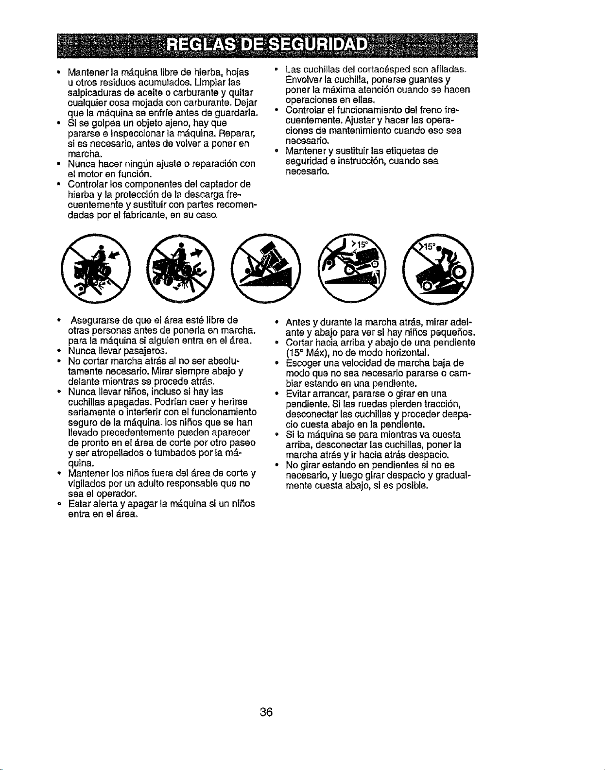
• Mantener la m_quina libre de hierba, hojas
u otros residues acumulados. Umpiar las
salpicaduras de aceite o carburante y quitar
cualquier cosa mojada con carburante. Dejar
que la m_quina se enfde antes de guardarlao
• Si se golpea un objeto ajeno, hay que
pamrse e inspsccionar la m_.quina. Reparar,
si es necesario, antes de votver a poner en
marcha.
• Nunca hacer ningun ajuste o reparaci6n con
el motor en funciSn.
• Controlar los componentes del captador de
hierba y la protecci6n de la descarga fre-
cuentemente y sustituir con partes recomen-
dadas por el fabricante, en su caso.
• Las cuchillas del cortac6sped son afiladaso
Envolver la cuchilla, ponerse guantes y
porter la m_ima atenci6n cuando se hacen
operaciones en ellas_
• Controlar et funcionamiento del freno fre-
cuentemente. Ajustar y hacer las opera-
ciones de mantenimiento cuando eso sea
necesario.
• Mantener y sustituir las ettquetas de
seguridad e instrucciSn, cuando sea
necesario.
• Asegurarse de que e! &rea est6 libre de
otras personas antes de poneda en marcha,
para la m_quina si alguien entra en el _.rea.
• Nunca Ilevar pasajeros.
• No cortar marcha arras al no ser absolu-
tamente necesarioo Mirar siempre abajo y
delante mientras se procede atr&so
• Nunca Ilevar niSos, incluso si hay las
cuchillas apagadaso Podrfan caer y herirse
sedamente o interferir con el funcionamiento
seguro de la m&quinao los nifos que se han
Ilevado precedentemente pueden aparecer
de pronto en el _.rea de corte por otro paseo
y ser atropellados o tumbados por la m_.-
quina.
• Mantener los niSos fuera del _.rea de corte y
vigilados por un adulto responsable que no
sea el operador.
• Estar alerta y apagar la m&quina si un niSos
entra en el _.reao
• Antes y durante la marcha atr_s, mirar adel-
ante y abajo para ver si hay niSos pequeSoso
• Cortar hacia arriba y abajo de una pendiente
(15° M_x), no de modo horizontal,
• Escoger una velocidad de marcha baja de
modo que no sea necesario pararse o cam-
biar estando en una pendiente.
• Evitar arrancar, pararse o girar en una
pendiente. Si las ruedas pierden tracci6n,
desconectar las cuchillas y proceder despa-
cio cuesta abajo en la pendiente.
• Si la m_quina se para mientras va cuesta
arriba, desconectar las cuchillas, porter la
marcha atr&s y ir hacia atr&s despacio.
• No girar estando en pendientes si no es
necesario, y luego girar despacio y gradual-
mente cuesta abajo, si es posible.
36
ESPECIFICACIONES DEL PRODUCTO
Capacidad y Tipo 2.5 Galones
de gasolina: Regular Sin Plomo
Tipo de Aceite: SAE 10W30 (Sobre 32°F)
API-SG-SL) SAE 5W30 (Debajo 32°F)
Capacidad de Con filtro: 51 oz
Aceite: Sin filtro: 35 oz.
_ujfai Champion RC12YC
Abertura: _030")
Ve]ocidad de Delante: 0-5°5
Recorrido (MPH): Marcha Atr_s: 0-2.4
Sistema de Carga: 15 Amps @ 3600 RPM
Baterra: Amp/Hr: 35
Min. CCA: 280
Case Size: U1 R
Torai6n dsl Perno
de la CuchUla: 45-55 Ft. Lbs.
FELICITACIONES por la compra de su tractor.
Ha side diseSado, planificado y fabricado para
darle la major confiabilidad y el major ren-
dimiento posibleo
En el caso de qus se encuentre con cualquier
problema qua no pueda solucionar f_cilmente,
haga el favor de ponerae en contacto con un
centro de servicio Sears o con un otro centro
de servicio cuatificadoo Cuenta con represent-
antes bien capacitados y competentes y con las
herramientas adecuadas para darle servicio o
para reparar este tractor.
Haga et favor de leer y de guardar este manual.
Estas instruc-ciones le permitir_n montar y
mantener su unidad en forma adecuada. Siem-
pre observe las "REGLAS DE SEGLIRIDAD"
RESPONSABILIDADES DEL CLIENTE
• Lea y observe las reglas de seguridad.
• Siga un programa regular de rnantenimiento,
cuidado y uso de su tractor.
° Siga las instrucciones descritas en las sec_
clones "Mantenimiento" y "Almacenamiento"
de este Manual del Duefio.
_ADVERTENClA: Este tractor viene equipa-
do con un motor de combusti6n interna y no se
debe usar sobre, o cerca, de un terreno no de-
sarrollado cubierto de bosques, de arbustos o
de c_sped, o menos qua el sistema de escape
del motor venga equipado con un amortiguador
de chispas qua cumpla con las leyes locales o
estatales (si existen)o Si se usa un amortigua-
dor de chispas, el operador debe rnantenerlo
en condiciones de trabajo eficientes.
En el estado de California, la lay exige 1o
anterior (Secci6n 4442 del "California Public
Resources Code"). Otros estados pueden
contar con otras leyes parecldas. Las leyes
federales se aplican en la tierras federales. Su
centro de Servicio mds cercano tiene disponible
amortiguadores de chispas para el silenciador.
(Vea la secci6n de Partes de Repuesto en el
manual Ingles del duefio.)
ACUERDOS DE PROTECCI6N PARA LA
REPARACI6N
Congratulaciones per su buena compra.
Su nuevo producto Craftsman® est,. diseSado
y fabricado para funcionar de modo fiable pot
muchos afios. Pero como todos los productos,
puede necesitar alguna reparaci6n de tanto
en tanto° En este caso tener un Acuerdo de
Protecci6n para la Reparaci6n puede hacerles
ahorrar dinero y fastidios.
Compre ahora un Acuerdo de Protecci6n para
la Reparaci6n y prot_gese de molestias y gas-
tos inesperados.
Un Acuerdo incluye los puntos siguientes:
• Servicto experto de nuestros 12.000
especialistas profesionales en la reparaci6n.
• Servlclo Illmltado sin cargo alguno pare
las partes y la mane de obra sobre todas las
reparaciones garantizadas.
• Sustitucl6n del producto si su producto
garantizado no puede ser arreglado.
° Descuento de110% sobre el precio corrisnte
det servicio y de las partes relativas al
servicio no cubiertas por el acuardo; tambi_n
el t0% menos sobre el precio corriente de
un control de mantenimiento preventivo.
° Ayuda r_pida per tel_fono - soporte
telef6nico per parts de un representante
Sears sobre preductos qua requieren un
arreglo en case, y adam,s una programaci6n
sobre los arreglos mds convenientes.
Cuando se ha comprado el Acuerdo, basta con
una tlamada telef6nica pare programar el servi-
cio. Puede llamar cuando quiera, dfa y noche o
fijar en Ifnea una cita para obtener el servicio.
Sears tiene mds de 12o000 especiaHstas
profesionales en la reparaci6n, qua tienen
acceso a rods de 4_5 miIIones de partes y
accesorios de calidad.
Este es el tipo de profesionalidad con qua
puede contar para ayudar a alargar la vida dsl
productoqua acaba de comprar, per muchos
aSos. tCompre hey su Acuerdo de Protecci6n
pare la Reparaci6nl
Se apllcan algunas Ilmltaciones y excluslo-
nes. Para conocer los precios y tener mds
Informacl6n, llama al 1-800-827-6655.
SERVIClO DE INSTALACl0N SEARS
Para la instalaci6n profesional Sears de
aparatos de casa, puertas de garaje,
calentadores de agua y otros importantes
artlculos para la casa, en U.S.A Ilamar a
1-800-4-MY-HOME®
37
Uaves
iiii I'I,I,II,,IIIILIIIIIIIIIIILJii
(1) Tubo de desag_)e
Hoja de pendiente
(2) Llaves
Su tractor nuevo ha sido montado en la f,_brica con la excepciSn de aquellas partes que no se han
montado pot razones de envfoo
Cuando en este manual se mencionan los
t_rminos "mano derecha" o "mano izquierda"
se refiere a cuando usted se encuentra en la
poslciSn de operaciSn (sentado/a detr_s del
volante de direcciSn),
PARA REMOVER ELTRACTOR DE
LA CAJA DE CART6N
DESEMPAQUE LA CAJA DE CART6N
1. Cortar a Io largo de las lfneas de puntos
en todos los cuatro pansies de cart6n.
Remover los paneles de cierre y aplanar los
paneles laterates,
2,. Remueva el embalage de cartSn del cap5 y
de la rejitla,
IMPORTANTE; Revise y remueva todas las
grampas en la corredera porqoe pueden per-
forar las llantas en donda e! tractor tiene que
rodar para salirse de ella.
VERIFIQUE LA BATERIA
1. Levante el asiento a la posici6n elevada
AVlSO: Siesta bateda esta utilizada despu_s
del mes y ago indicado sobre la etiqueta (L) (la
etiqueta qua se encuentra entre los terminales),
cargue la baterfa por un m[nimo de una hora
a 6-10 amps. (Vea "Bateria" en la sacci6n de
Mantenimento de este manual),
AJUSTE EL ASIENTO
1. Levante el asiento y afloje la periila del
ajusteo
2, Baje el asiento a la posiciSn de operaciSn y
si_ntese en el asiento,
3. Deslics el asiento hasta que llegue a una
posiciSn cSmoda, que le permita presionar
el pedal dal embrague/freno completamente
hasta abajo.
4, DesmSntese del asiento sin mover su
posiciSn ajustada,
5. Levante el asiento y apriete la manilla de
ajuste en forma segura.
Manti}ade
AVISO: Ahora puede rodar o conducir su trac-
tor fuera de la corredera° 8iga las slguientes
instruccionas para remover el tractor de la
c_redera.
DMERTENCIA: Antes de empezar, fear,
entender y seguir todas las instrucciones
presentes en la secci6n de Operaciones de
este manual, Asegurarse que el tractor estd en
un _.rea bien ventilada. Asegurarse que la zona
delante del tractor est_ libre de otras personas
y objetos,
PARA HACER RODAR EL TRACTOR
FUERA DE LA CORREDERA (Vea la
secci6n de la operaci6n para la Iocali-
dad y la functdn de los controles)
t. Apriete la manilla de levantamiento del
pist6n y, levante la palanca de levantamien-
to del accssorio a su posiciSn m_s altao
2, Suelta e! freno de estacionamiento presion*
ando el pedal del frenoo
38
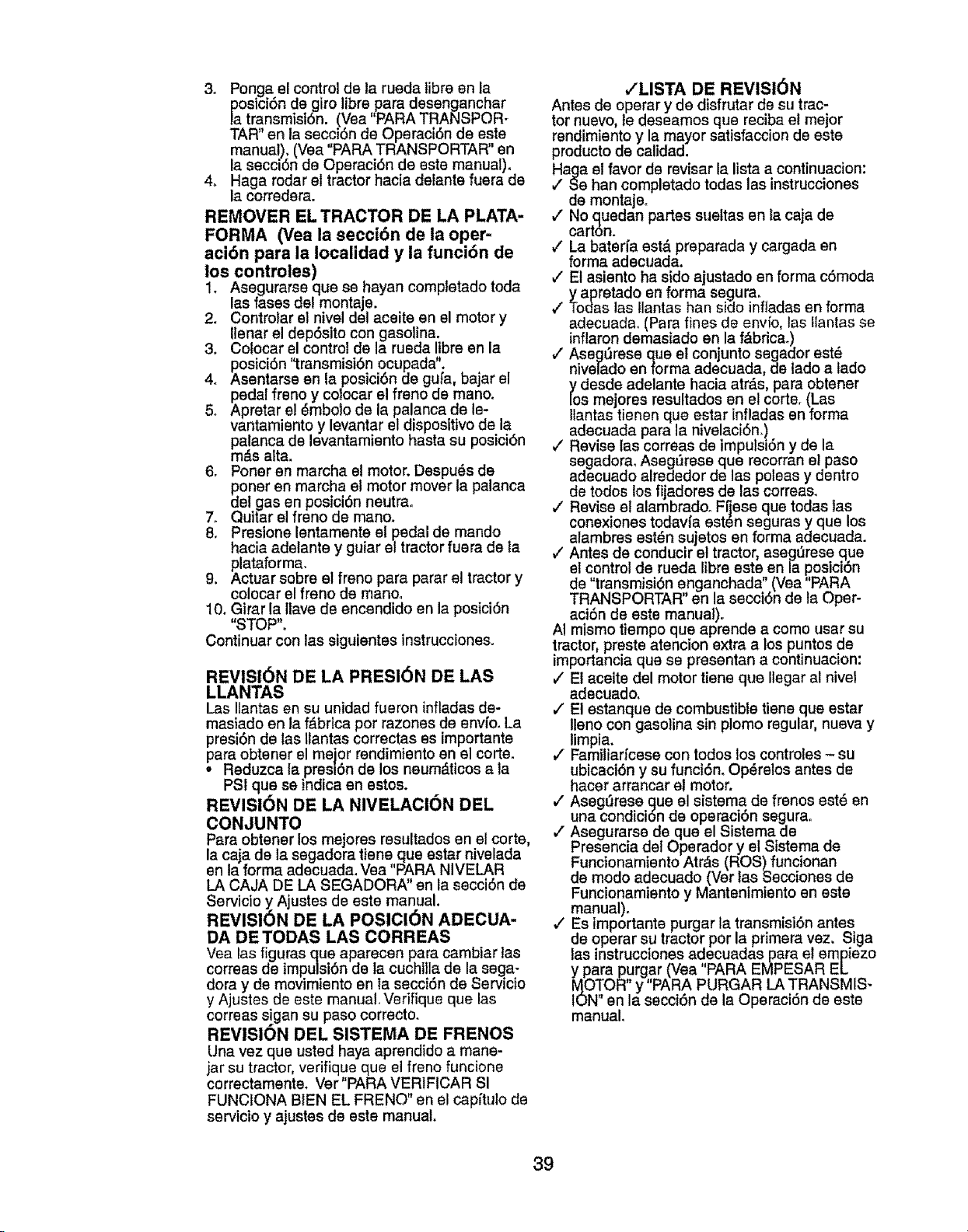
3. Ponga el control de la rueda libre en la
_aoslctonde giro libre para desenganchar
transmist6n. (Vea "PARA TRANSPOR-
TAR" en la secci6n de Operaci6n de este
manual). (Vea "PARA TRANSPORTAR" en
la secci6n de Operaci6n de este manual)_
4. Haga rodar el tractor hacia detante fuera de
la corredera.
REMOVER EL TRACTOR DE LA PLATA-
FORMA (Vea la secci6n de ia oper-
aci6n para la localidad y la funci6n de
los controles)
1. Asegurarse que se hayan completado toda
las rases del montaje.
2. Controlar el nivel del aceite en el motor y
Uenar el dep6sito con gasolina.
3. Colocar el control de la rueda libre en la
posici6n "transmisi6n ocupada".
4. Asentarse en la posicibn de gufa, bajar el
pedal freno y colocar el freno de mano.
5. Apretar el 8mbolo de la palanca de le-
vantamiento y levantar el dispositivo de la
palanca de levantamiento hasta su posici6n
m,_s alta.
6. Porter en marcha el motor. Despu_s de
poner en marcha el motor mover la palanca
del gas en posici6n neutrao
7. Quitar el freno de mano.
8. Presione lentamente el pedal de mando
hacia adelante y guiar el tractor fuera de la
plataforma.
9. Actuar sobre el freno para parar el tractor y
colocar el freno de manoo
10. Girar la llave de encendido en la posici6n
"STOP".
Continuar con las siguientes instrucciones.
REVISI6N DE LA PRESI6N DE LAS
LLANTAS
Las Itantas en su unidad fueron infladas de-
masiado en la fdbrica por razones de envfo. La
presi6n de las Uantas correctas es importante
para obtener el me]or rendimiento en el torte.
• Reduzca la presl6n de los neumdticos a la
PSI que se indica en estos.
REVISi6N DE LA NIVELAOION DEL
CONJUNTO
Para obtener los mejores resultados en el corte,
la caja de la segadora tiene que estar nivelada
en la forma adecuada.Vea PARA NIVELAR
LA CAJA DE LA SEGADORA" en la secci6n de
Servicio y Ajustes de este manual,
REVISI6N DE LA POSICI6N ADECUA-
DA DETODAS LAS CORREAS
Vea las figuras que aparecen para cambiar las
correas de impulsi6n de la cuchilla de la sega-
dora y de movimlento en la secci6n de Servicio
y Ajustes de este manual. Verifique que las
correas s!gan su paso correcto.
REVISION DEL SISTEMA DE FRENOS
Una vez que usted haya aprendido a mane-
jar su tractor, verifique que el freno funcione
correctamente. Ver"PARA VERIFICAR SI
FUNCIONA B1EN EL FRENO" en el capftulo de
servicio y ajustes de este manual.
,/LISTA DE REVISI6N
Antes de operar y de disfrutar de su trac-
tor nuevo, le deseamos que reciba el mejor
rendimiento y la mayor satisfaccion de este
producto de calidad.
Haga el favor de revisar la lista a continuacion:
J Se han completado todas las instrucciones
de montajeo
_" No quedan partes sueltas en la caja de
cart6n.
€' La baterfa est,. preparada y cargada en
forma adecuada.
,/El asiento ha sido ajustado en forma c6moda
y apretado en forma segura.
#" Todas las llantas han sido infladas en forma
adecuadao (Para fines de envio, las llantas se
inflaron demasiado en la f&brica.)
,/AsegQrese que el conjunto segador estd
nivelado enforma adecuada, de lado a lado
_/odeSdeadelante hacia atrd.s, para obtener
s mejores resultados en el corte. (Las
liantas tienen que estar infladas en forma
adecuada para la nivelaci6n.)
J Revise las correas de impulsi6n y de la
segadora° Aseg_rese que recorran el paso
adecuado alrededor de las poleas y dentro
de todos los fijadores de las correas.
v" Revise el alambradoo Fijese que todas las
conexiones todavfa est_n seguras y que los
alambres est_n sujetos en forma adecuada.
,/Antes de conducir et tractor, asegQrese que
el control de rueda libre este en la ,posici6n
de "transmisi6n enganchada" (Vea PARA
TRANSPORTAR" en la secci6n de la Oper-
aci6n de ests manual).
AI mismo Uempo que aprende a como usar su
tractor preste atencion extra a los puntos de
importancia que se presentan a cont nuacion:
v" El aceite del motor tiene que Ilegar al nivel
adecuado,
,/El estanque de combustible tiene que estar
Ileno con gasolina sin plomo regular, nueva y
limpia.
,/Familiarfcese con todos los controtes - su
ubicaci6n y su funci6n. Op_relos antes de
hacer arrancar el motor.
_' Asegt'jrese que el sistema de frenos est6 en
una condici6n de operaci6n segurao
,_ Asegurarse de que el Sistema de
Presencia del Operador y el Sistema de
Funcionamiento Atr_s (ROS) funcionan
de modo adecuado (Vet las Secciones de
Funcionamiento y Mantenimiento en este
manual).
,/ Es lmportante purgar la transmisi6n antes
de operar su tractor por la primera vez, Siga
las instrucciones ad,ecuadas para el empiezo
y para pur.gar (Vea PARA EMPESAR EL
MOTOR y PARA PURGAR LA TRANSMIS-
ION" en la secci6n de la Operaci6n de este
manual.
39
Estos sfmbolos pueden aparecer sobre su tractor o en la literatura proporcionada con el producto.
Aprencla y comprenda sus significados.
R N H L
MARCHA ATFL_S
6
MOTOR
APAGADO
NEUTRO
SISTEMA
ALTO BAJO
G
MOTOR MOTOR
ENCEND1DO ENMAROHA ESTAOIONAMIENTO SEGADORA
ESTRA_GU. P_PtDO LENTO
LACION
(@)
FRENODE ALTURADELA LEVANTAMIENTO
DELASEGADORA
FUNCIONAMIENTO
_D ATR_S (ROs)
LUCES
ENSENDIDAS COMBUSTIBLE
ACCESORIO DI=L ACCESORIO DEL
EMBRAGUE EMBRAGUE
ENGANCHADO DESENGANCHADO
RUEDA LIBRE
(SolamentepBra los
modeloeautomBtfco)
MARCHA MAROHA PALANOADE MANDO PEDALDE FRENO/
ATR_S HACIAADHLANTE CRUCERO DH£MBRAGUE
PELIGRO,GUARDELAS
MANOSY LOSPIESLEJOS MANTENGAEL PELIGROSDE
AREADESPEJADA PENDIENTES
(VeaIaeecc16nde leeraglasde esgurtdsd)
PELIGRO Indice un petlgro qua, si no se evIta,
provoca muerte o lealonea gravaeo
ADVERTENCIA fndtca un peligro qua, sl no se svlta,
puade provocar muerta o lestonea graves.
PRECAUCI6N }ndlca un pellgro qua, s] no se evita,
puada provocer lestones Ilgeras o moderadas.
&
No segulr las stgulentes instruccfones
puede provocar herldas o muerte, Los
slmbolos de avlso de saguddadse utitfzan
para Identificar lnformacfones de seguddad
relattvas a pelfgros qua puedenprovocar la
muerte, hertdas graves y/o daCios ala
m_quina_
PRECAUCI(SN cuando se utIIlza sin el s[mbolode avtso,
lndlca una situeckSnqua puede provocar det_os al
tractor yto al motor,
SUPERFICIES CALIENTES Indlcaun peltgro qua,
sl no se evita, puede provocar ls muerta, lealones
graves y/o danoa e la mdqulne.
FUEGO Indtca un pellgro qua, si no se evlta, puede
provocsr la muarte, lealonee graves y/o danoe
ata mdqulna.
40
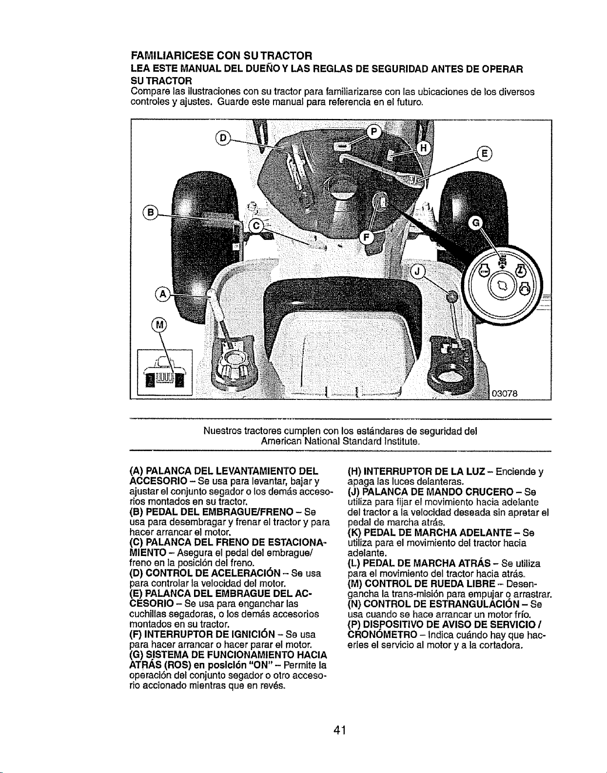
FAMILIARICESE CON SU TRACTOR
LEA ESTE MANUAL DEL DUEllO Y LAS REGLAS DE SEGURIDAD ANTES DE OPERAR
SU TRACTOR
Compare las ilustraciones con su tractor para familiarizarse con lae ubicaciones de los diversos
controles y ajustes. Guarde este manual para referencia en el futuro.
O3078
Nuestros tractores cumplen con los est&ndares de seguridad del
American National Standard Institute.
(A) PALANCA DEL LEVANTAMIENTO DEL
ACCESORIO - Se usa para levantar, bajar y
ajustar el conjunto segador o los dem_.sacceso-
dos montados en su tractor,
(B) PEDAL DEL EMBRAGUFJFRENO - Se
usa para desembragar y frenar el tractor y para
hacer arrancar el motor.
(C) PALANCA DEL FRENO DE ESTAClONA-
MIENTO - Asegura el pedal del embrague/
freno en la posiciSn del freno.
(D) CONTROL DE ACELERACI6N - Se usa
para controlar la velocidad del motor.
(E) PALANCA DEL EMBRAGUE DEL AC-
CESORIO - Se usa para enganchar las
cuchillas segadoras, o los dem_.s accesorios
montados en su tractor.
(F) INTERRUPTOR DE IGNIC16N - Se usa
para hacer arrancar o hacer parar el motor.
(G) SISTEMA DE FUNCIONAMIENTO HACIA
ATRAS (ROS) en poslcl6n "ON" - Permite la
operaciSn dsl conjunto segador o otro acceso-
rio accionado mientras que en revds.
(H) INTERRUPTOR DE LA LUZ- Enciende y
apaga las luces delanteras.
(J) PALANOA DE MANDO CRUCERO - Se
utiliza para fijar el movimiento hacia adelante
del tractor a la velocidad deseada sin apretar el
pedal de marcha atr_s.
(i0 PEDAL DE MARCHA ADELANTE - Se
utiliza para el movimiento del tractor hacia
adelante.
(L) PEDAL DE MARCHA ATRAS - Se utiliza
para el movimiento del tractor hacia atr_.a.
(M) CONTROL DE RUEDA LIBRE .- Desen-
gancha la trans.misi6n para empujar o arrastrar.
(N) CONTROL DE ESTRANGULAGION - Se
usa cuando se hace arrancar un motor if[o.
(P) DIS POSITIVO DE AVISO DE SERVIClO /
CRONOMETRO - Indica cu_ndo hay que hac-
erles el servicio al motor y a la cortadora.
41
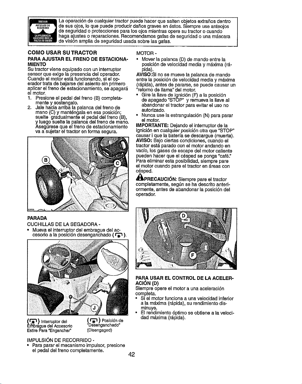
La operaci6n de ctJalquier tractor puede hacer que salten objetos extrafios dentro
de sus ojos, to qua puede producir dafios graves en _stoso Siempre use anteojos
de seguridad o protecciones pars los ojos mientras opera su tractor o cuando
hags ajustes o reparaciones. Recomendamos gafas de seguridad o una mdscara
de visi6n amplia de seguridad usada sobre las gafas_
COMO USAR SU TRACTOR
PARA AJUSTAR EL FRENO DE ESTACIONA-
MIENTO
Su tractor viene equipado con un interruptor
sensor qua exige la presencia del operador.
Cuando el motor est& funcionando, si el .op.
erador trata de bajarse del asiento sin pnmero
aplicar el freno de estacionamiento, sa apagard
e/motor.
1. Presione el pedal del freno (B) completa_
mente y sostengalo.
2. Jale hacia arriba la palanca det freno de
mano (C) y mant_ngala en esa posici6n;
suelte gradualmente el pedal del freno (B),
y luego suelte la palanca del freno de mano_
Asegerese qua el freno de estacionamiento
va a sujetar el tractor en forms segura.
MOTOR -
• Mover la palanca (D) de mando entre la
posicidn de ve!ocidad media y m_.xima (rd-
pida).
AVISO:Si no se mueve la palanca de mando
entre la posici6n de velocidad media y mdxima
(r,_pida), antes de pararse, se puede causar un
"retorno de llama" del motor.
° Gire la Ilave de ignicidn (F) a la posicidn
de apagado "STOP" y remueva la llave a!
abandonar el tractor para evitar el uso no
autodzado.
° Nunca use la estrangulaci6n (N) pars parar
el motor.
IMPORTANTE: Dejando el interruptor de la
ignicidn en cualquier posicidn otra qua "STOP"
causar i que la baterra se descargue (muerta).
AVISO: Bajo ciertas condiciones, cuando el
tractor est_ parado con et motor andando en
vacfo, los gases de escape del motor caliente
pueden hacer que el c_sped se ponga "caf_"
Para eliminar esta posibilidad, siempre pare
el motor cuando pare el tractor en &reas con
cdspedo
,_PRECAUCI6N: Siempre pare el tractor
completamente, seg0n se ha descrito anted-
ormente, antes de abandonar la posicidn del
operador.
PARADA
CUCHILLAS DE LA SEGADORA -
• Mueva el interruptor del embrague del ac-
cesorio a la posici6n desenganchado ( _ ).
l_) Enterruptor del
rague del Accesorlo
Estire Pars "Enganchsr"
( _ ) PosFc16nde
"Desenganchado"
(Disengaged)
IMPULSI6N DE RECORRIDO -
° Pars parar el mecanismo impulsor, presione
el pedal del freno completamente.
PARA USAR EL CONTROL DE LA ACELER-
ACI6N (D)
Siempre opera el motor a una aceleraci6n
completa.
• Si el motor funciona a una velocidad inferior
a la mdxima (rdpida), su rendimiento dis-
minuye.
° El rendimiento 6primo se obtiene a la veloci-
dad mdxima (r_pida).
42
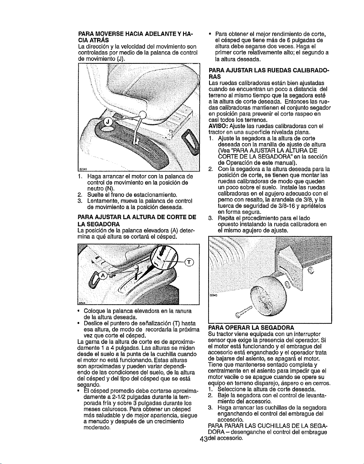
PARA MOVERSE HACIA ADELANTE Y HA-
ClA ATRAS
La direcciSn y la velocidad del movimiento son
controladas por medio de ta palanca de control
de movimiento (J).
_O4t
I, Haga arrancar el motor con la patanca de
control de movimiento en la posici6n de
neutro (N).
2o Suelte el freno de estacionamiento,
3. Lentamente, mueva la palanca de control
de movimiento a la posici6n deseada.
PARA AJUSTAR LA ALTURA DE CORTE DE
LA SEGADORA
La posiciSn de la palanca elevadora (A) deter-
mina a qu6 altura se cortard el c6sped.
° Coloque la palanca elevadora en la ranura
de la altura deseadao
Para obtener e! mejor rendimiento de corte,
el c6sped qua tiene md.s de 6 pulgadas de
altura debe segarse dos veceso Haga el
primer corte relativamente alto; el segundo a
la altura daseadao
PARA AJUSTAR LAS RUEDAS CALIBRADO-
RAS
Las ruedas calibradoras estdn bien ajustadas
cuando se encuentran un poco a distancia del
terreno al mismo tiempo qua la segadora est6
a la altura de corte deseada. Entonces las rue-
das calibradoras mantienen el conjunto segador
en posiciSn para prevenir el corte raspao en
casi todos los terrenos.
AMISO: Ajuste las ruedas calibradoras con el
tractor en una superficie nivelada plana.
1. Ajuste la segadora a la altura de corte
deseada con la manilla de ajuste de altura
(Vea "PARA AJUSTAR LA ALTURA DE
CORTE DE LA SEGADORA" en la secciSn
de Operaci6n de este manual),
2. Con la segadora a la altura deseada para la
posici6n de corte, se tienen qua montar las
ruedas calibradoras de modo qua queden
un poco sobre el suelo. Instale las ruedas
calibradoras en el agujero adecuado con ef
perno con resalto, la arandela de 3/8, y la
tuerca de seguridad de 3/8-16 y apri6telos
en forma segura.
3. Repita el procedimiento para el lado
opuesto instalando la rueda calibradora en
el mismo agujero de ajuste.
• Deslice el puntero de seSalizaciSn (T) hasta
esa altura, de modo de recordarla la pr6xima
vez qua corte el cdsped.
La garna de la altura de corte es de aproxima-
damente I a 4 pulgadas. Las alturas se miden
desde el suelo a la punta de la cuchilla cuando
el motor no est,_ funcionando. Estas alturas
son aproximadas y pueden vadar dependi-
endo de las condiciones del suelo, de la altura
del c6sped y del tipo del c_,sped qua se est,.
segandoo
• El cdsped promedio debe cortarse aproxima-
damente a 2-1/2 pulgadas durante la tem-
porada frla y sobre 3 pulgadas durante los
meses calurosos. Para obtener un c6sped
m_.s saludable y de major apariencia, siegue
a menudo y despu_s de un crecimiento
moderado.
PARA OPERAR LA SEGADORA
Su tractor viene equipada con un interruptor
sensor qua exige la presencia del operador. Si
el motor estd funcionando y el embrague del
accesorio est_ enganchado y el oparador trata
de bajarse del asiento, se apagard el motor.
Tiene qua mantenerse sentado completa y
centralmente en el asiento para impedir que el
motor vacile o se apague cuando se opera su
equipo en terreno disparejo, _.spero o en cerros.
1. Seleccione la altura de corte deseada.
2o Baje la segadora con el control de levanta-
miento del accesorioo
3, Haga arrancar las cuchitlas de la segadora
enganchando el control de! embrague del
accesorio.
PARA PARAR LAS CUCHILLAS DE LA SEGA-
DORA - desenganche el control de! embrague
43det accesorio_
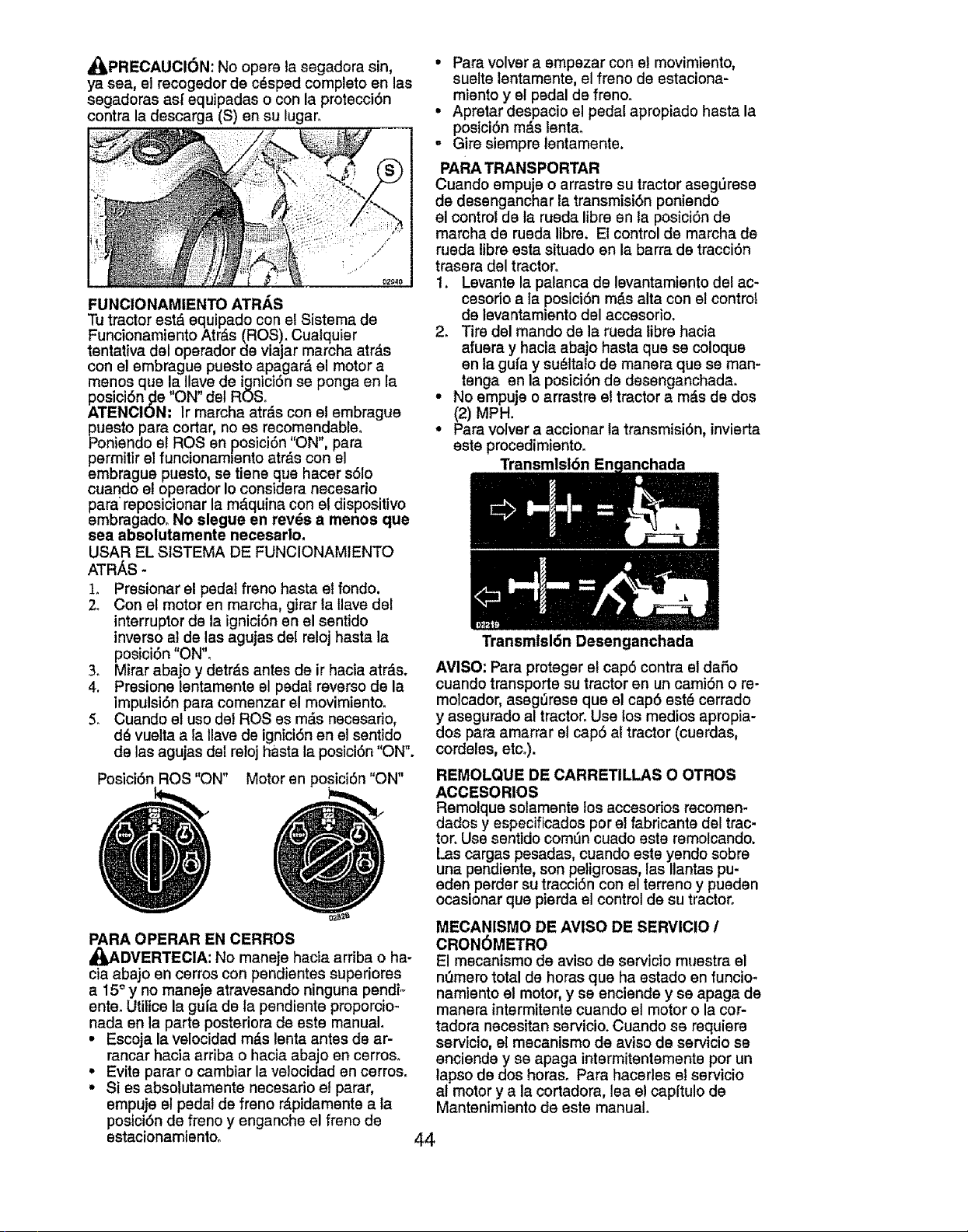
_PRECAUCI6N: No opere la segadora sin,
ya sea, et recogedor de c_sped completo en las
segadoras am"equipadas o con la protecci6n
contra la descarga (S) en su lugar..
FUNCIONAMIENTO ATRAS
Tu tractor estd equipado con el Sistema de
Funcionamiento Atr&s (ROS). Cualquier
tentath,a del operador de viajar marcha atr&s
con e! embrague puesto apagar_ el motor a
menos que la Ilave de ignici6n se ponga en la
posici6n_e I'ON" del ROSo
ATENCION. Ir marcha atr_.s con el embrague
_uesto para cortar, no es recomendable,
niendo el ROSen posici6n "ON", para
permitir el funcionam_ento atr&s con el
embrague puesto, se tiene que hacer s61o
cuando el operador Io considera necesario
para reposicionar la m_.quina con el dispositivo
embragado, No slegue en rev_s a menos que
sea absolutamente necesarlo.
USAR EL SfSTEMA DE FUNCIONAM1ENTO
ATRAS -
1. Presionar el pedal freno hasta el fondo,
2. Con el motor en marcha, girar la llave del
interruptor de la ignici6n en el sentido
inverso al de las agujas del reloj hasta la
posici6n "ON"o
3. Mirar abajo y detr_s antes de ir hacia atrds.
4. Presione lentamente el pedal reverso de la
impulsi6n para comenzar el movimiento.
5. Cuando el uso del ROSes m_s necesario,
d_ vuetta a la llave de igniciSn en el sentido
de las agujas del re!oj hasta la posici6n "ON".
Posici6n ROS "ON" Motor en posici6n "ON"
PARA OPERAR EN CERROS
_ADVERTECIA: No maneje hacia arriba o ha-
cia abajo en cerros con pendientes superiores
a 15° y no maneje atravesando ninguna pendio
ente. Utitice la gufa de la pendiente proporcio_
nada en la parte posteriora de este manual.
• Escoja la velocidad m_s lenta antes de ar-
rancar hacia arriba o hacia abajo en cerroso
• Evite parar o cambiar la velocidad en cerros.
• Si es absotutamente necesario el parar,
empuje el pedal de freno r_.pidamente a la
posici6n de freno y enganche el freno de
estacionamiento.
• Para volver a empezar con el movimiento,
suelte lentamente, el freno de estaciona-
miento y el pedal de freno°
• Apretar despacio el pedal apropiado hasta la
posici6n m_s lenta_
- Gire siempre lentamente,
PAPA TRANSPORTAR
Cuando empuje o arrastre su tractor asegerese
de desenganchar la transmisi6n poniendo
el control de la rueda libre en la posici6n de
marcha de rueda libre. El control de marcha de
rueda libre esta situado en la barra de tracci6n
trasera del tractor°
1. Levante la palanca de levantamiento del ac-
cesorio a la posiciSn m_s alta con el control
de levantamiento del accesorio.
2_ Tire del mando de la rueda libre hacia
afuera y hacia abajo hasta que se coloque
en la gufa y su_ltato de manera que se man-
tenga en la posici6n de desenganchada.
• No empuje o arrastre et tractor a m_s de dos
(2) MPH.
° Para volver a accionar la transmisi6n, invierta
este procedimiento.
llst6n Enc
Transmisl6n Desenganchada
AVISO: Para proteger el cap6 contra el dafio
cuando transporte su tractor en un camiSn o re-
molcador, asegOrese que el cap6 est_ cerrado
y asegurado al tractor. Use los medtos apropia-
dos para amarrar el cap5 al tractor (cuerdas,
cordeles, etc_).
REMOLQUE DE CARRETILLAS O OTROS
ACCESORIOS
Remolque solamente los accesorios recomen-
dados y especificados por e! fabricante del trac-
tor. Use sentido comun cuado este remolcando.
Las cargas pesadas, cuando este yendo sobre
una pendiente, son petigrosas, las Ilantas pu-
eden perder su tracci6n con el terreno y pueden
ocas=onar que pierda el control de su tractor°
MECANISMO DE AVISO DE SERVICIO /
CRON6METRO
El mecanismo de aviso de servicio muestra el
n_3merototal de horas que ha estado en funcio-
namiento el motor, y ee enciende y se apaga de
manera intermitente cuando et motor o la cor-
tadora necesitan servicio. Cuando se requiere
servicio, el mecanismo de aviso de servicio se
enciende y se apaga intermitentemente pot un
lapso de dos horas. Para hacerles el servicio
al motor y a la cortadora, lea el cap(tulo de
Mantenimiento de este manual.
44
NOTA: El dispositivo de aviso de servicio
funciona cuando la Ilave de igniciSn o arranque
se encuentra en cualquier posici6n menos
en "STOP" ("PARE"). A fin do garantizar la
precisi6n de la lectura, aseg[)rese de_ue el,,
arranque permanezca en la posici6n STOP
cuando el motor est6 apagado.
ANTES DE HACER ARRANCAR
EL MOTOR
REVISE EL NIVEL DE ACEITE DEL MOTOR
El motor en su tractor ha side enviado desde la
f_brica Ileno con aceite de calidad para veranoo
1. Revise e! aceite del motor con el tractor en
terreno nivelado.
2. Levante y quite la varilia indicadora de
nivel de relleno del aceite; timpie el aceiteo
Reinserte la variila en el tube y emp_jela
hacia abajo firmemente en su lugar.
Remueva y lea el nivel del aceite. Si es
necesario, agregue aceite hasta se Ilegue
a la marca de llano (FULL) en la varilla
indicadora de niveL No Io Ilene demasiado.
• Para la operaciSn en clima frfo, debe cambiar
el aceite para peder arrancar m_.s f_cilmente
(Vea "Tabla de Viscosidad Del Aceite" en la
secci6n de Mantenimento de este manual).
° Para cambiar e! aceite del motor, vea la sec-
ci6n de Mantenimiento en este manual.
AGREGUE GASOLINA
• Llene el estanque de combustible. Llene has_
ta la parte inferior del cuello de relleno del
estanque de gasolina. No Io liana demasiado,
Use gasolina regular, sin plomo, nueva y lim-
pia con el mfnimo de 87 octanes. (El use de
gasolina con plomo aumentar_, los depSsitos
do 5xido de plomo y carbono y se reducir& la
duraci6n do la v_Ivula)o No mezcle el aceite
con la ,_asolina. Pare asegurar qua la gaso-
lina utihzada sea fresca compre estanques
los cuales puedan ser utilizados durante los
_primeros 30 dias.
A_,PRECAUCl0N: Limpie el acelte o el com-
bustible derramado. No almacene, derrame o
use gasolina cerca de una llama expuesta.
IMPORTANTE: Cuando se opere en temperatu-
ras per debajo de 32°F (O°C) use gasotina de
invierno limpia y nueva para auedar a asegurar
un buen arranque en clima frfoo
PRECAUClON: Combustibles mezclados con
alcohol (ccnocidos come gasohol, o el use do
etanol o metanol) pueden atraer la humedad,
ta que conduce a la separaci6n y formaci6n de
acidos durante el almacenamiento. La gasolina
acfdica puede dafar el sistema del combustible
de un motor durante el almacenamiento. Para
evitar los problemas con el motor, se debe vaci-
ar el sistema do combustible antes do guardarlo
per un perfodo de 30 dfas o m_s. Vacre el
estanque de combustible, haga arrancar el
motor y h_.galo funcionar hasta qua las Ifneas
del combustible y el.carburador queden vacfos,
La pr6xima temporada use combustible nuevoo
Vea las Instrucciones para el Almacenamiento
para m_.s informaci6n_ Nunca usa productos de
limpieza para el motor o para el carburador en
el estanque del combustible pues se pueden
producir daSos permanentes, 45
PARA HACER ARRANCAR EL MOTOR
AI hacer arrancar el motor per la primera vez o
si so ha acabado el combustible del motor, se
necesitar& tiempo para el arranque extra para
mover el combustible desde el estanque hasta
el motor_
1. Aseg6rese qua el control de rueda tibre
este en la posici6n enganchada.
2, Si_ntase en el sill6n on la posici6n de
operaci6n, suelte el pedal de! freno y ponga
el freno de estacionamiento.
3. Mueva e! embrague del accesorio a la
posiciOn desenganchado disengaged,
4. Mueva el control de la aceleraciOn a la
posici6n do r_.pido.
5. Tire el control de estrangulaciOn a la
posiciOn do estrangulaci6n para el arranque
de un motor frio. Para el arrancar un motor
caliente el use del control de la estrangu-
laci6n puede qua no sea necesarioo
AViSO: Antes do arrancar, lea las instruccio-
nes siguientes para el arranque en clima fr[o y
templado.
6. Inserte la Ilave en la ignici6n y gire ta Ilave
on e! sentido qua giran las mani!las del reloj
a la posiciOn de arranque start, y suelte la
Ilave tan pronto come arranque el motor.
No haga funcionar el arrancador continu-
amente per m_.s de quince segundos per
minute. Si el motor no arranca despu_s de
varies intentarlos, mueva el control de la
estrangulaci6n hacia adentro, espere unos
cuantos minutes y trate de nuevo, Si el mo-
tor sigue sin funcionar, estire del control de
la estrangulaci6n y trate de nuevo.
ARRANQUE CON TIEMPO TEMPLADO (50°
Y M/_S)
7. Cuando arranque el motor, empuje el con-
trol de la estrangulaci6n hasta qua el motor
empiece a funcionar m_.s suavemente. Si
el motor empieza a funcionar mal, estire
det control de la estrangulaci6n un poco
per unos cuantos segundos y entonces
continu_ a empujar lentamente el control.
• Los accesorios y e! embrague de suelo
ahora puede ser utilizados. Si el motor no
acepta esta carga, vuelva a arrancar el motor
para permitirle qua se caliente per un minute,
utilizando el estrangulador come describido
arriba.
ARRANQUE CON TIEMPO FRiO (50°Y
MENOS)
7. Cuando arranque el motor, empuje lenta-
mente el control de la estrangulaci6n hacia
adentro hasta qua el motor empiece a
funcionar suavementeo Siga empuj_ndolo
poco a poco permitiendo qua el motor acepte
pequeSos cambios de velocidad y carga,
hasta qua este completamente hacia aden-
tro. Si el motor empieza a funcionar mal, as-
tire del control de la estrangulaci6n un poco
per unos cuantos segundos y contim_e a
empujar el control hacia adentroo Esto puede
requerir qua el motor se caliente per unos
cuantoe minutes, depende de la temperatura.
CALENTAMIENTOPARALATRANSMtSION
AUTOMATICA
Antesdeconducirla unidadenuntiempofrfo,
latransmisiSndebesercalentadacomolas
instruccionessiguientes:
1. AsegSresequeeltractorestesituadoen
unasuperficienivelada.
2. Aliviee!frenodeestacionamientoy dejeque
elfrenovuelvaala posiciSndeoperaci6n.
3. PermitaquelatransmisiSnsecaliente
duranteunminuto.Estopuedeserechodu-
ranteeltiempodecalentamientodelmotor.
• Losaccesoriospuedenserutilizadosdurante
el periododelrecalentamientodelmo-
tordespu_squelatransmisi6nhallesido
calentaday puederequerirquael controlde
la estrangulaci6nseaestiradounpoco.
AVIS0:Siseencuentraamuchaattura(sobre
3000pies)oenclimafrfo(pordebajode32°F
[O°C]),la mezcladelcombustibledelcarburador
debeserajustadapareel mejorrendimiento
delmotor.(Vea"PARAAJUSTARELCARBU-
RADOR"enlasecci6ndeServicioyAjustesde
estemanual)_
PURGARLATRANSMISI6N
_¢_,PRECAUCl6N; Nunca enganche o desen-
ganche la palanca del control de rueda libre
cuando el motor esta funcionando.
Pare asegurar la operaci6n y ejecuciSn adec-
uada, es recomendado que la transmisi6n sea
purgada antes de operar el tractor pare la prim-
era vez. Este proceso remover& cualquisr aim
adentro de la transmisi6n que se halle formado
durante el transporte de su tractor.
IMPORTANTE: Si por acaso su transmisi6n
debe set removida pare servicio o reemplazo,
debe ser purgada despu_s de la reinstalaci6n y
antes de operar et tractor.
1. Para mayor seguridad, ubique el tractor
en una superficie niveiada, despejada de
cualquier objeto y abierta, con el motor
apagado y el freno de mano puesto.
2. Desenganche la transmisi6n poniendo el
control de rueda libre en la posid6n de
desenganchado (Vea "PARA EL TRANS-
PORTE" en esta secci6n de este manual).
3. Sentado en el asiento del tractor, empiece
el motor. Despu_s que este corriendo el
motor, mueva el control de estrangulaci6n
ala posici6n de lento. Con la palanca de
rueda libre en la posici6n de neutral (N),
desenganche lentamente el embrague/el
A_. freno del pedal.
PRECAUOION: En el transcurso del paso 4,
puede que de pronto se pongan en movimiento
tas ruedas.
4. Mueva la palanca del control de movimiento
ala posici6n total de adelante y suj6tela
durante cinco (5) segundos. Mueva la
palanca hacia la posici6n total de marcha
atr_s y suj6tela durante cinco (5) segundos_
Repita este proceso tres (3) veceso
5. Mueva la palanca del control de movimiento
ala posici6n de neutro (N). Apague el motor
y embrague el freno de estacionamientoo
6. Enganche la transmisi6n poniendo el
control de rueda libra en la posici6n de
conducir (Vea "PARA TRANSPORTAR" en
esta secci6n del manual).
7. Sentado en el asiento del tractor, empiece
el motor. Despu_s que este corriendo el
motor, mueva el control de estrangulaciSn
media (1/2) velocidad. Con la palanca de
control de movimiento ala posici6n de
neutro (N), lentamente desenganche e!
embrague/el freno del pedal.
8. Mueva lentamente la patanca de control
de movimiento hacia adeIante, despu#s
que el tractor se mueva aproximadamen-
te cinco (5) pies, mueva lentamente con
la palanca de control de movimiento ata
posici6n contrariao Despu6s que el tractor
se mueva aproximadamente unos cinco (5)
pies vuelva a poner la patanca de control
de movimiento en la posici6n de neutro (N).
Repita este procedimiento la palanca de
control de movimiento tres (3) veces.
Su transmisi6n esta ahora purgado y dispuesto
pare la operaci6n normal°
46
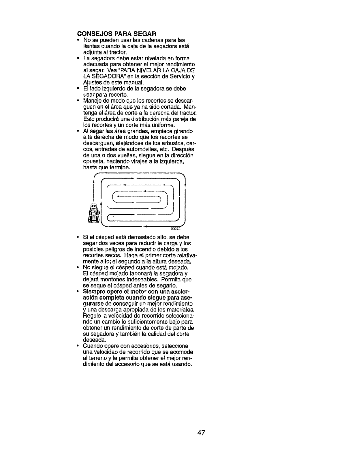
CONSEJOS PARA SEGAR
• No se pueden usar las cadenas para las
llantas cuando la caja de la segadora estd
adjunta al tractor.
• La segadora debe estar nivelada an forma
adecuada para obtener el mejor rendimiento
al segar. Vea "PARA NIVELAR LA CAJA DE
LA SEGADORA" en la secci6n de Servicio y
Ajustas de este manual.
• El tado izquierdo de la segadora se debe
usar para recorte.
• Maneje de mode qua los recortes se descar-
guen sn el _,rea qua ya ha side cortada. Man-
tenga e! drea de corte a la derecha del tractor.
Esto producir_, una distribuci6n mds parsja de
los recortes y un corte m_s uniforms.
• AI segar las Eireagrandes, empiece girando
a la derecha de mode qua los recortes se
descarguen, alej_,ndose de los arbustos, car-
cos, entradas de autem6viles, etc. Despu_s
de una o dos vueltas, siegue en la direcci6n
opuesta, haciendo virajes a la Izquierda,
hasta qua termine.
f
1
O0272
• Si el c_sped estd damasiado alto, se debe
segar dos vsces para reducir la carga y los
posibles peligros de incendio debido a los
recortes secos. Haga et primer corte relativa-
manta alto; el segundo a ta altura deseada.
• No siegue el c_sped cuando est,. mojado°
El c_sped mojado taponard la segadora y
dejard montones indeseables. Permita que
se seque el cdsped antes de segarlo.
• Siempre opere el motor con una aceler-
acl6n completa cuando slegue para ase-
gurarse de conseguir un major rendimiento
y una descarga apropiada de los materiales.
Regule la velocidad de recorrido selecciona-
ndo un cambio lo suficientemente bajo para
obtener un rendimiento de corte de parts de
su segadora y tambi_n la calidad del corte
deseada_
• Cuando opera con accesorios, seleccione
una velocidad de recorrido qua se acomode
ai terreno y le permita obtener el major ren-
dimiento del accesorio qua se est,. usando.
47
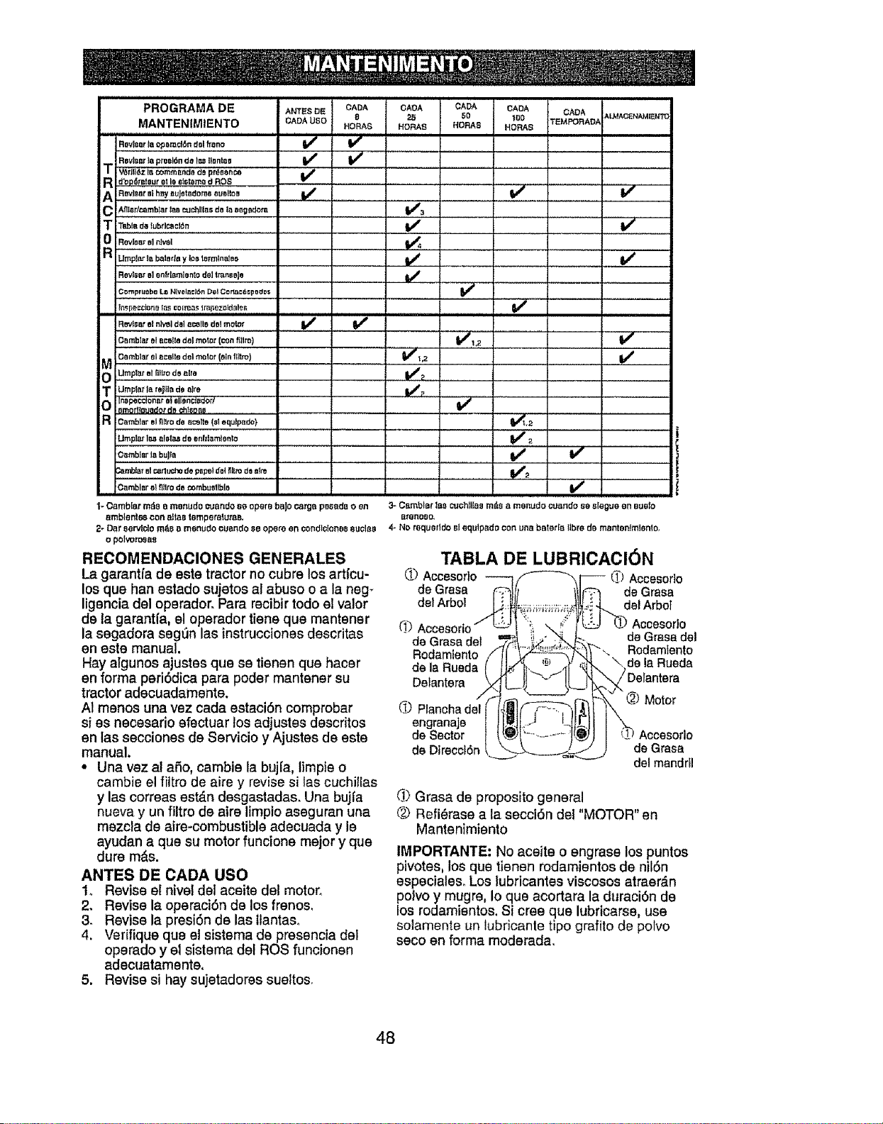
CADA J,LMACENAMI_W_I_
TEMPORAD,_
........................Vfe,,
v'
v'
v'
v'
i,i1,1 iiiii iiiiii ii iiii
v"
Vr,1,2
V"
v"
v"
if''
v'
v'
v'
% Cambier rode a mertudo cuando s@opere bajo ca_s posa_a o en 3- CBmblatlaP,cuchlllaem_s a menudo cu_]ndoBe BIBgUBen BUBIO
_mbl@ntescon _t_e=t_mperalu_. _reno_o,
2- Dat serviclo mds _,menudo c_Bndo_,eopera en c_ndl_IonBsBUOIaB 4- NO r_querIdoBIequtpado con unBbaterIa libra de manter_lmienio,
o polvoro_as
RECOMENDACIONES GENERALES
La gar_nt_a de este tractor no cubre los art_cu-
los qua han estado sujetos al abuso o a la neg_
ligencia del operadoroPara recibirtodo el valor
de la garant_a, el operador tiene qua mantener
la segadora segGn las instrucciones descritas
en este manual.
Hay algunos ajustes qua se tienen qua hacer
en forma peri6dica para poder mantener su
tractor adecuadamente.
A1menos una vez cada estaci6n comprobar
si es necesario efectuar los adjustes descritos
en las secciones de Servicio y Ajustes de este
manual.
• Una vez al a6o, cambie la buj[a, limpie o
cambie el _tro de aire y revise si las cuchiIIas
y las correas es_n desgastadas, Una bujl'a
nueva y un _tro de aire limpio aseguran una
mezcla de airs-combustible adecuada y le
ayudan a qua su motor funcione major y que
dure m6s.
ANTES DE CADA USO
t, Revise el nivel del aceite del motor_
2. Revise la operaci6n de los frenos,
3, Revise la presi6n de las llantaso
4. Verifique que et sistema de presencia del
operado y el sistema del ROS funcionen
adecuatamente,
5. Revise si hay sujetadores sueltos_
TABLA DE LUBRICACION
O Accesorlo Accesodo
de Grasa de Grasa
del Arbol del Arbot
Accesorlo
deGrass del
Rodamtento
"\ de la Rueda
de Grass det
Rodamiento
de la Rueda
Deiantera
Q Plancha dal
engranaje
de Sector
de Dlrecci6n
Motor
Accesorlo
de Grasa
del mandril
(1_)Grasa de proposito general
('_ Refi6rase a la secci6n del "MOTOR" en
Mantenimiento
IMPORTANTE: No aceite o engrase los puntos
pivotes, los qua tienen rodamientos de nil6n
especialeso Los lubricantes viscosos atraer_.n
polvo y mugre, Io qua acortara la duracidn de
los rodamientos. Si cree qua lubricarse, use
solamente un lubricanle tipo grafito de polvo
seco en forma moderada,
48
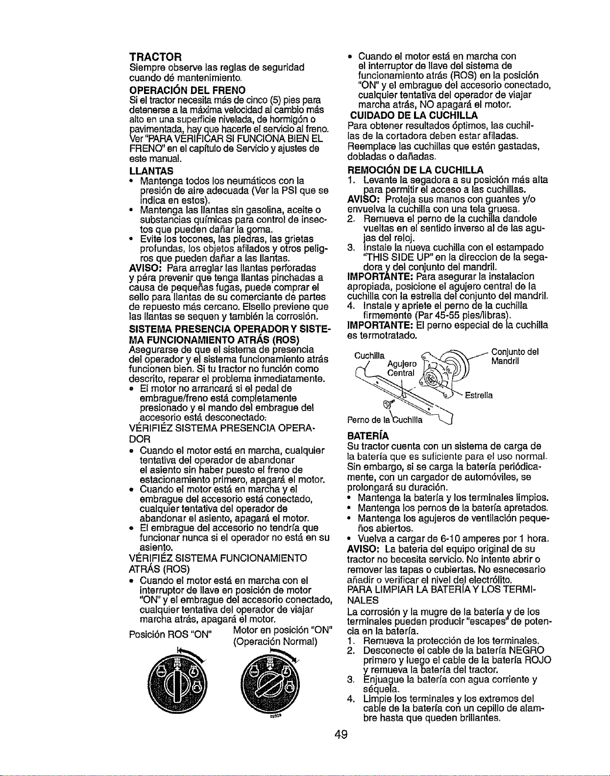
TRACTOR
Siempre observe las reglas de seguridad
cuando d_ mantenimiento.
OPERAOI6N DEL FRENO
$i el tractor necesita m_s de cinco (5) pies para
detenerse a la m_Lximavelocidad al cambio m_.s
alto en una supefficie nivelada, de hormigSn o
pavimentada, hay qua hacede el servicioat freno.
Ver"PARA VERIFICAR SI FUNCIONA BIEN EL
FRENO" en el capffulo de Se_cio y ajustes de
este manual.
LLANTAS
• Mantenga todos los neum_.ticos con la
presi6n de aire adecuada (Ver la PSI qua se
mdica en estos).
° Mantenga las Ilantas sin gasolina, aceite o
substancias qufmicas para control de insec_
toe qua pueden daSar ta gomao
° Evita los tocones, las piedras, las grietas
profundas, los objetos afilados y otros pelig-
ros qua pueden daSar alas Ilantas.
AVISO: Para arreglar las Ilantas pefforadas
y p_ra prevenir qua tenga Ilantas pinchadas a
causa de pequeSas fugas, puede comprar et
sello para Ilantas de su comerciante de partes
de repuesto m_.s cercano. Elsello previene qua
tas Ilantas sa sequen y tambidn la corrosi6n,
SISTEMA PRESENCIA OPERADOR Y SISTE-
MA FUNCIONAMIENTO ATRAS (RO$)
Asegurarse de qua el sistema de presencia
det operador y el sistema funcionamiento atr&s
funcionen bien. Si tu tractor no funci6n come
descrito, reparar et problema inmediatamente.
= El motor no arrancar_ si el pedal de
embrague/freno est,. completamente
presionado y el mando del embrague del
accesorio est,. desconectad_
V_RIFII_Z SISTEMA PRESENCIA OPERA-
DOR
,, Cuando e! motor estd en marcha, cualquier
tentativa del operador de abandonar
el asiento sin haber puesto el freno de
estacionamiento primero, apagar_, el motor.
• Cuando el motor est& en marcha y el
embrague del accesorio est_ conectado,
cualqule r tentativa del operador de
abandonar el asiento, apagar& el motor.
• El embrague del accesorio no tendrfa que
funcionar nunca si el operador no est,. en eu
asiento,
VI_RIFII_Z SISTEMA FUNCIONAMIENTO
ATR,&.S(ROS)
= Cuando el motor est& en marcha con el
interrupter de Ilave en posici6n de motor
Posici6n ROS "ON" Motor en posici6n "ON"
(Operaci6n Normal)
• Cuando el motor estd en marcha con
et interrupter de !lave del sistema de
funcionamiento atr_,s (ROS) en la posici6n
"ON" y el embrague del accesorio conectado,
cualquier tentativa del operador de viajar
marcha atr,_s, NO apagar_, el motor.
CUIDADO DE LA CUCH1LLA
Para obtener resultados 6primes, las cuchil-
tas de la cortadora deben estar afiladaso
Reemplace las cuchiltas qua est_n gastadas,
dobladas o danadae.
REMOCl6N DE LA CUCHILLA
1. Levante la segadora a su posici6n m_.s alta
para permitir el acceso a las cuchitlas.
AVISO: Proteja sue manes con guantes y/o
envuelva la cuchilla con una tela gruesa.
2. Remueva el perno de la cuchilla dandole
vueltas en el sentido inverse al de las agu-
jas del reloj.
3. tristate la nueva cuchilla con el estampado
'q'HIS SIDE UP" en la direccion de la sega-
doray del conjunto del mandril.
IMPORTANTE: Para asegurar la instalacion
apropiada, posicione el agujero central de la
cuchilla con la estrella del conjunto del mandril°
4. lnstale y apriete el perno de la cuchilla
firmemente (Par 45-55 piesilibras).
IMPORTANTE: El perno especial de la cuchilla
es termotratado.
Cuchllla _ _ /i. ConJuntodel
BATERiA
Su tractor cuenta con un sistema de carga de
la baterfa que es suficienle para el use normal.
Sin embargo, si se carga la baterfa peri6dica-
mente, con un cargador de autom6viles, se
pro!ongar_, su duraci6n.
• Mantenga la baterfa y los terminales limpios.
° Mantenga los pernos de la baterla apretados.
= Mantenga los agujeros de ventilaci6n peque-
5os abiertoe_
= Vuelva a cargar de 6-10 amperes per 1 hera.
AVISO: La bateria del equipo original de su
tractor no becesita servicio. No intente abrir o
remover las tapas o cubiertas. No esnecesario
a,Sadiro verificar el nivel del electr61ito.
PARA LIMPfAR LA BATER[A Y LOS TERMI-
NALES
La corrosi6n y la mugre de la baterla y de los
terminales pueden producir "escapes" de poten-
cia en la baterfa°
1. Remueva la protecci6n de los terminales.
2. Desconecte el cable de la baterfa NEGRO
primero y luego el cable de la baterfa ROJO
y remueva labateria del tractor.
3_ Enjuague la baterfa con agua corriente y
s_quela.
4. Limpie los terminales y los extremes del
cable de la baterfa con un cepillo de alam-
bre hasta qua queden brlllantes_
49
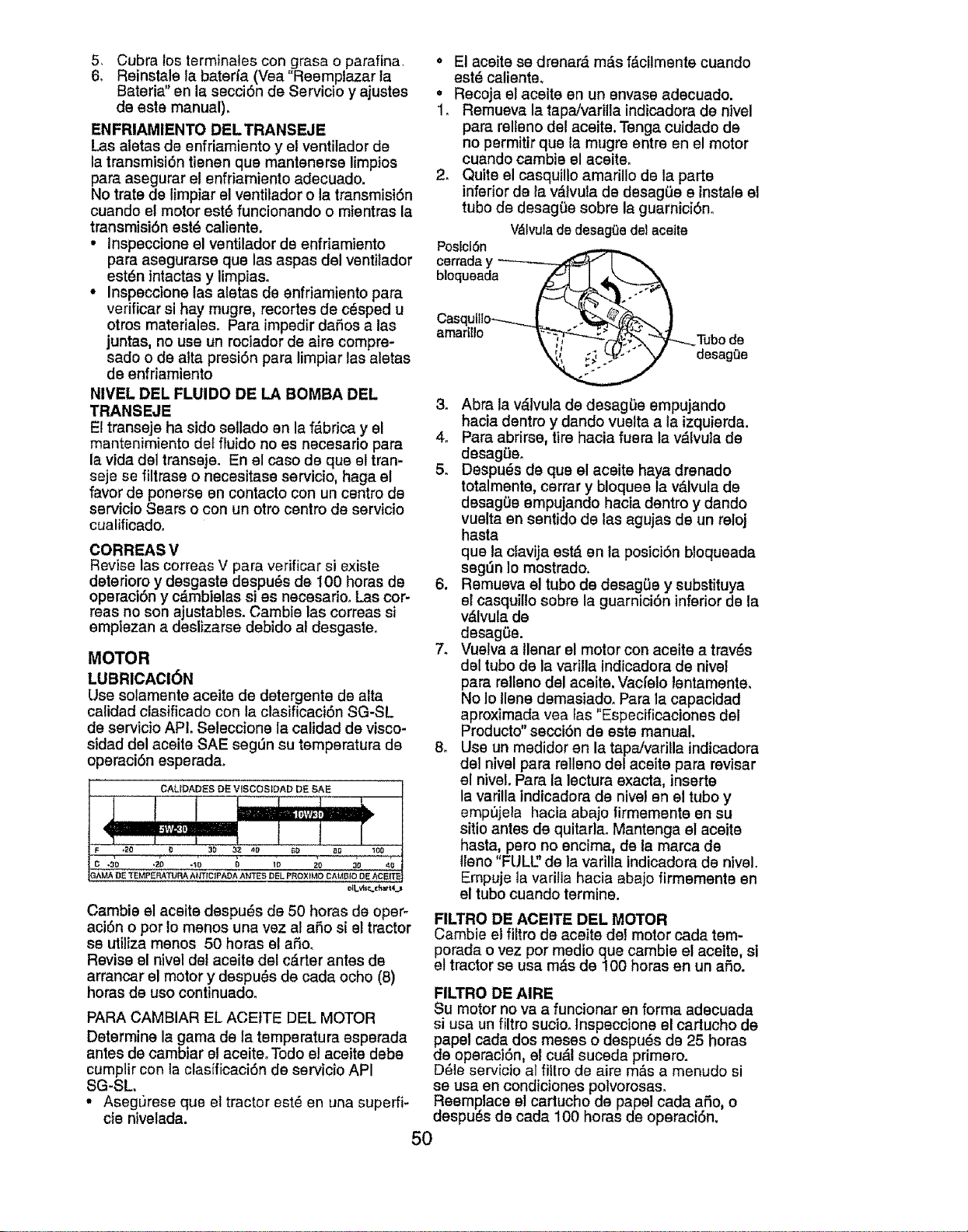
5, Cubra los terminales con grass o parafina,
6, Reinstale la bateria (Vea"Reemplazar la
Bateria" en la secciSn de Servicio y ajustes
de este manual),
ENFRIAMIENTO DELTRANSEJE
Las aletas de enfriamiento y el ventilador de
la transmisi6n tienen que mantenerse limpios
para asegurar el enfriamiento adecuado.
No trate de limpiar el ventilador o la transmisi6n
cuando e! motor est_ funcionando o mientras la
transmisi6n est_ caliente.
• Inspeccione el ventilador de enfriamiento
pars asegurarse que las aspas de! ventitador
est6n intactas y limpias.
• Inspeccione las aletas de enfriamiento para
verificar si hay mugre, recortes de c_sped u
otros materiales. Pars impedir dafios a las
juntas, no use un rociador de airs compre-
sado o de alta presi6n para limpiar las aletas
de enfriamiento
NIVEL DEL FLUIDO DE LA BOMBA DEL
TRANSEJE
Et transeje ha sido sellado en la f_.brica y el
mantenimiento det fiuido no es necesario pars
la vida del transeje. En el caso de que el tran-
seje se filtrase o necesitase servicio, haga el
favor de ponsrse en contacto con un centro de
servicio Sears o con un otro centro de servicio
cualificadoo
CORREAS V
Revise las correas V para verificar si existe
deterioro y desgaste despu6s de 100 horas de
operaci6n y cdmbielas si es necesario_ Las cor-
teas no son ajustables. Cambie las correas si
empiezan a deslizarse debido al desgasteo
MOTOR
LUBRICACI6N
Use solamente aceite de detergents de alta
calidad clasificado con la clasificaci6n SG-SL
de servicio APL Seleccione la calidad de visco-
sided del aceite SAE segOn su tempsratura de
operaci6n esperada.
Cambie el aceite despuds de 50 horas de opero
aci6n o por Io menos una vez al afio si el tractor
se utiliza menos 50 horas el afio,
Revise el nivel del aceite del c,_rter antes de
arrancar el motor y despu_s de cada ocho (8)
horas de uso continuadoo
PARA CAMBIAR EL ACE1TE DEL MOTOR
Determine la game de la temperature esperada
antes de cambiar el aceiteo Todo e! aceite debe
cumplir con la clasificaci6n de servicio API
SG-SL,
• Asegurese que el tractor sst_ en una supeffi-
cie nivelada.
• El aceite se drenard rods f&cilmente cuando
estd calienteo
• Recoja el aceite en un envase adecuado.
1, Remueva la tapa/varilla indicadora de nivel
pars relleno del aceite. Tenga cuidado de
no permitir que la mugre entre en el motor
cuando cambie el aceite.
2. Quite el casquillo amarillo de la parts
inferior de la v,_lvuta de desagOe e instals el
tubo de desagOe sobre la guarnici6n,
V_lvulade desageedel eceIte
PoslclSn
cerreday ----------
amarillo _
"__Tubo de
_j desagOe
3, Abra la vdtvula de desagSe empujando
hacia dentro y dando vuetta ala izquierda.
4. Pars abrirse, tire hacia fuera la vdlvula de
desag_e.
5, Despu_s de que el aceite hays drenado
totalmente, cerrar y bloquee la v&lvula de
desag0e empujando hacia dentro y dando
vuelta en sentido de las agujas de un retoj
haste
que la clavija estd en la posici6n bloqueada
seg_n Io mostrado.
6. Remueva el tubo de desaglJe y substituya
el casquillo sobre la guarnici6n inferior de la
vdlvula de
desagOe.
7_ Vuelva a llenar el motor con aceite a trav_s
del tubo de la varilla indicadora de nivel
pars relleno del aceite. Vacfeio lentamente.
No Io liens demasiado, Para la capacidad
aproximada vea fas "Especificaciones del
Productd' secci6n de este manual.
8. Use un medidor en la tapa/varilla indicadora
del nivel para rellsno del aceite pars revisar
el nivel. Para la lecture exacta, inserts
la varilla indicadora de nivel en el tubo y
emp_jela hacia abajo firmemente en su
sitio antes de quitadao Mantenga el aceite
haste, pero no encima, de la marca de
tleno "FULU' de la varilta indicadora de nivel,
Empuje la varilla hacia abajo firmemente en
el tubo cuando termine.
FILTRO DE ACEITE DEL MOTOR
Cambie e! filtro de aceite de! motor cada tem-
porada ovez por medio que cambie el aceite, si
et tractor se usa m_s de100 horas en un afio.
FILTRO DE AIRE
Su motor no va a funcionar en forma adecuada
si usa un filtro sucio, tnspeccione el cartucho de
dPapelcada dos meses o despu_s de 25 horas
e operaci6n, el cu_.l suceda primero.
D61eservicio al filtro de sire m&s a menudo si
se usa en condiciones polvorosas.
Reemplace e! cartucho de papel cads afio, o
despu_s de cads 100 horas de operaci6n.
5O
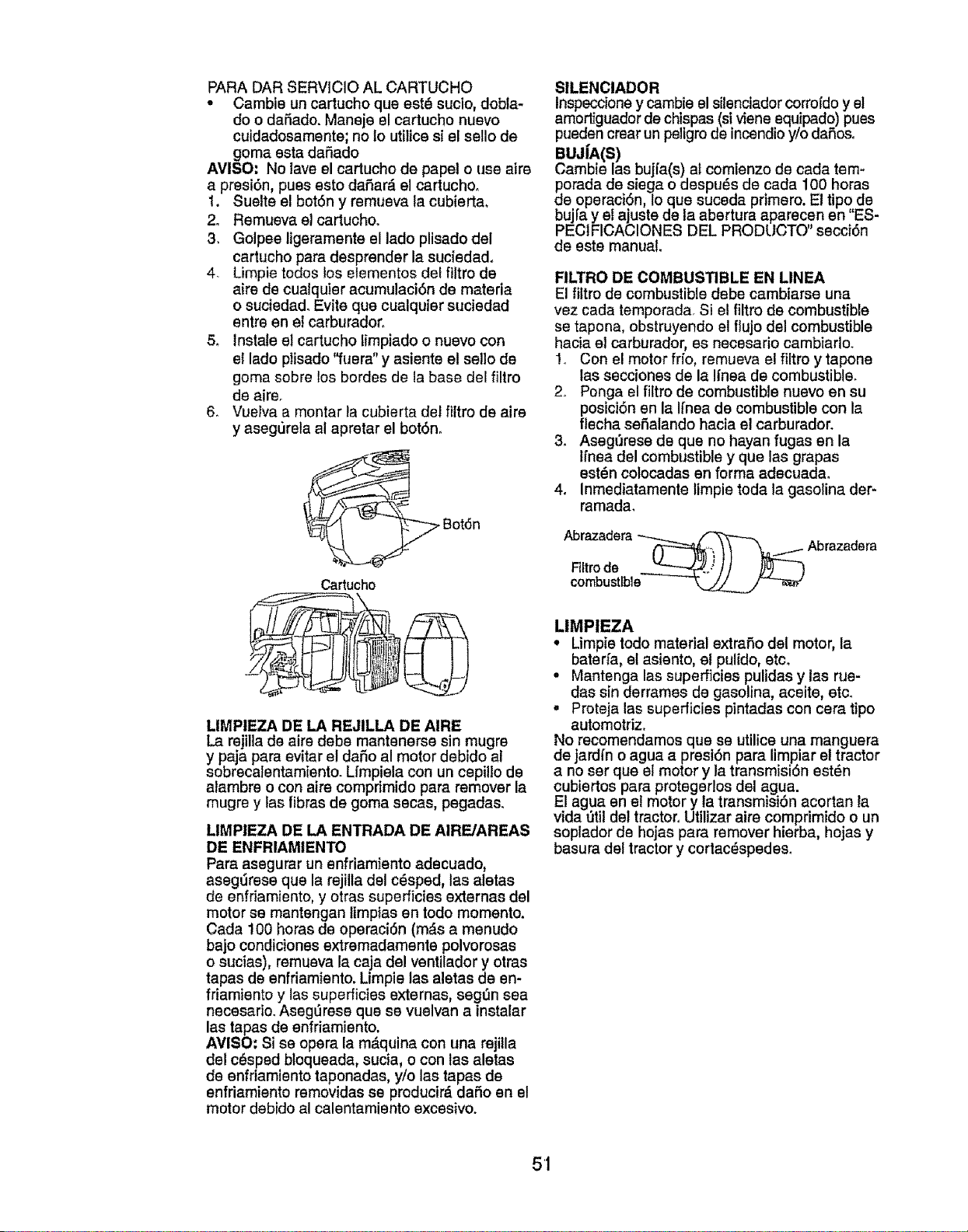
PARA DAR SERVICIO AL CARTUCHO
° Cambie un cartucho que est6 sucio, dobla-
do o daSado. Mansje el cartucho nuevo
cuidadosamente; no 1outilice si el sello de
goma esta daSado
AMISO. No lave el cartucho de papel o use airs
a presi6n, pUBSesto daSar_, el cartucho,
1. Suelte el bot6n y remueva la cubierta.
2. Remueva el cartucho.
3. Golpee ligeramente el lado plisado del
cartucho para desprendsr la suciedad.
4. Limpie todos los eiementos det filtro de
aire de cualquier acumulaci6n de materia
o suciedad. Evite que cualquisr suciedad
entre en el carburador,
5_ Instate el cartucho limpiado o nuevo con
el lado plisado "fuera" y asiente et sello de
goma sobre los bordes de la base del filtro
de airs.
6. VueIva a montar la cubierta dei filtro de aire
y aseg0rela al apretar el bot6n.
Cartucho
LIMPIEZA DE LA REJILLA DE AIRE
La rsjilla de airs debs mantenerse sin mugre
y paja para evitar el dafio al motor debido al
sobrecalentamisnto. Lfmpiela con un cepillo de
alambre o con airs comprimido para remover la
mugre y fas fibras de goma secas, pegadas.
LIMPIEZA DE LA ENTRADA DE AIRE/AREAS
DE ENFRIAMIENTO
Para asegurar un enfriamiento adecuado,
asegLirsse que la rejilla del c_sped, las aletas
de enfriamiento, y otras superficies externas del
motor se mantengan timpias en todo momento.
Cada !00 horas de operaci6n (mds a menudo
bajo condiciones extremadamente polvorosas
o sucias), remueva la caja de! ventilador y otras
tapas de enfriamiento. Limpie las aletas de en-
friamiento y las superficies externas, segt_n sea
necesario. Aseg0rese que se vuelvan a instalar
las tapas de enfriamiento.
AMISO: Si se opera la m,_quina con una rejilla
del c_spsd bloqueada, sucia, o con tas aletas
de enfriamisnto taponadas, y/o las tapas de
enfriamiento removidas se producir_ dafio en et
motor debido al calentamiento excesivo.
SILENCIADOR
Inspeccione y cambie el silenciador corrofdo y e!
amortfguador de chispas (si visne equipado) puss
pueden crsar un pellgro de incendio y/o dafios.
BUJ|A(S)
Cambie las bujfa(s) al comienzo de cada tem-
porada de siega o despu_s de cada 100 horas
de operaciOn, Io que suceda primero. El tipo de
bujfa y el ajuste de la abertura aparecen en "ES-
PEC1FICACIONES DEL PRODUCTO" sscci6n
de este manual.
RLTRO DE COMBUSTIBLE EN LINEA
El filtro de combustible debe cambiarse una
vez cada temporada. Si el filtro de combustible
se tapona, obstruyendo el flujo del combustible
hacia el carburador, es necesario cambiarlo.
1,. Con e! motor frio, remueva el filtro y tapone
las sscciones de la Ifnsa de combustible.
2,. Ponga el filtro de combustible nuevo en su
posici6n en la Ifnea ds combustible con la
flecha sefialando hacia el carburador.
3. Asegt_rese ds que no hayan fugas en la
Ifnea del combustible y que las grapas
est_n colocadas en forma adecuada.
4. Inmediatamente limpie toda la gasolina der-
ramada.
Abrazadera_ _
Flitrode "-"T'_..,/ / / _)u) 3
cornbustlble
LIMPIEZA
• Limpie todo material extra_o del motor, la
bater_a, el asiento, et pulido, etc.
• Mantenga las superficies pulidas y las rue-
das sin derrames de gasolina, aceite, etc_
, Proteja las superficies pintadas con cera tipo
automotriz.
No recomendamos que se utilice una manguera
de jardfn o agua a presiSn para limpiar et tractor
a no ser que el motor y la transmisi6n estdn
cubiertes para protegerlos del agua.
El agua en el motor y la transmision acortan ta
vida _til ds! tractor.Utilizar aire comprimido o un
soplador de hojas para remover hierba, hojas y
basura del tractor y cortac_spedes_
51
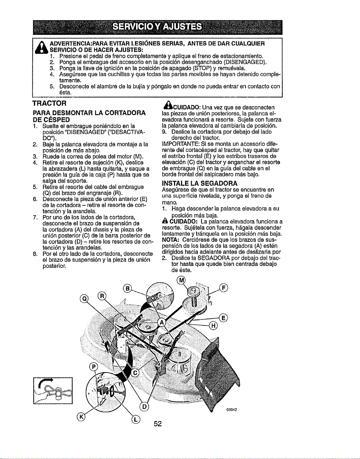
_ DVERTENCIA:PARA EVITAR LESI6NES SERIAS, ANTES DE DAR CUALQUIER
SERVICIO 0 DE HACER AJUSTES:
1o Presione el pedal de freno completamente y apiique el freno de estacionamiento.
2. Ponga et embrague det accesorio en la posici6n desenganchado (DISENGAGED).
3. Ponga la llave de ignici6n en la posici6n de apagado (STOP) y remu_vala.
4. Aseg6rese que las cuchillas y que todas las partes movibles se hayan detenido comple-
tamente,
5. Desconecte el alambre de la bujfa y p6ngalo en donde no pueda entrar en contacto con
_sta.
TRACTOR
PARA DESMONTAR LA CORTADORA
DE ClaSPED
1. Suelte el embrague poni_ndo)o en la
posici6n "DISENGAGED" ("DESACTIVA-
DO").
2_ Baje la palanca elevadora de montaje ata
posici6n de m_s abajo.
3o Ruede la correa de potea del motor (M).
4. Retire el resorte de sujeci6n (K), deslica
la abrazadera (L) hasta quitarla, y saque a
presi6n la gufa de la caja (P) haste que se
salga del soporte.
5, Retire el resorte del cable del embrague
(Q) del brazo del engranaje (R).
6. Desconecte la pieza de uni6n anterior (E)
de la cortadora - retire el resorte de con-
tenci6n y la arandela_
7_ Por uno de los lados de la cortadora,
desconecte el brazo de suspensi6n de
la cortadora (A) del chasis y la pieza de
uni6n posterior (C) de la barra posterior de
la cortadora (D) - retire los resortes de con-
tenci6n y las arandelas_
8. Por el otro lado de la cortadora, desconecte
el brazo de suspensi6n y la pieza de uni6n
posterior.
4_I)CUIDADO: Una vez que se desconecten
las piezas de uni6n posteriores, la palanca el-
evadora funcionar& a resorte, Sujete con fuerza
la palanca elevadora al cambiarla de posici6n.
9. Deslice la cortadora por debajo del lado
derecho del tractor.
IMPORTANTE: Si se monta un accesorio dife*
rente del cortac_sped al tractor, hay que quitar
el estribo frontal (E) y los estribos traseros de
elevaci6n (C) det tractor y enganchar el resorte
de embrague (Q) en la gufa del cable en el
borde frontal del salpicadero m&s bajoo
INSTALE LA SEGADORA
Asegt]rese de que el tractor se encuentre en
una superficie nivelada, y ponga e! freno de
mano.
1_ Haga descender fa palanca elevadora a su
posici6n m_.s baja.
_1)CUIDADO." La palanca elevadora funciona a
resorte, Suj_tela con fuerza, h_gala descender
lentamente y tr_.nquela en la posici6n m,_s baja.
NOTA; Cerci6rese de que los brazos de sus-
pensi6n de los lados de la segadora (A) est_n
dirigidos hacia adelante antes de deslizarta pot
2o Deslice la SEGADORA por debajo del trac-
tor hasta que quede bien centrada debajo
de _ste.
03042
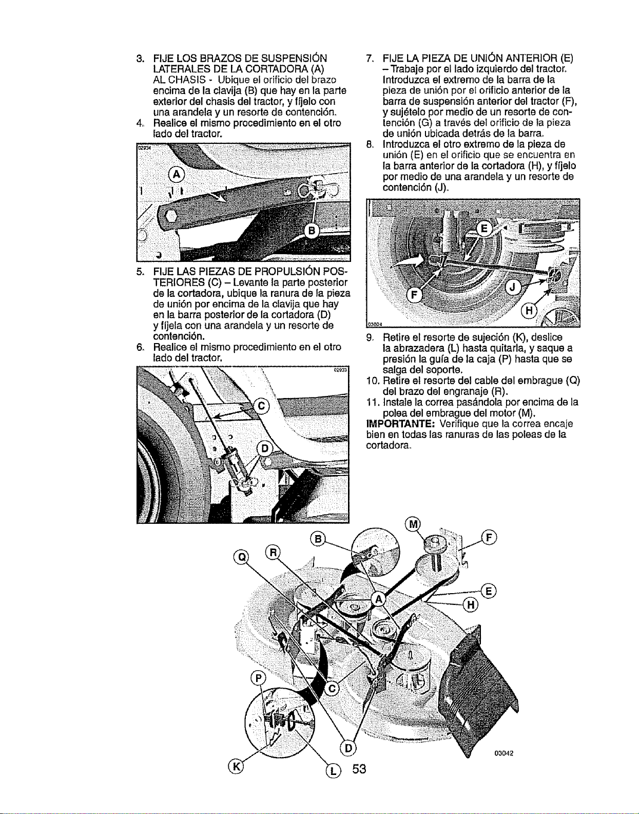
3. FIJE LOS BRAZOS DE SUSPENSION
LATERALES DE LA CORTADORA (A)
AL CHASIS - Ubique ei orificio del brazo
encima de la ctavija (B) que hay en la parte
exterior del chasis del tractor, y fi]elo con
una arandela y un resorle de contenci6n.
4. Realice el mismo procedimiento en el otro
lado de! tractor.
7. FIJE LA PIEZA DE UNION ANTERIOR (E)
-Trabaje por el lado izquierdo del tractor.
Introduzca el extremo de la barra de la
pieza de uni6n por el orificio anterior de la
barra de suspensi6n anterior del tractor (F),
y suj_telo por medio de un resorle de con-
lenci6n (G) a trav_s dei orificio de la pieza
de uni6n ubicada detr_s de la barra.
8. Introduzca el otro extremo de la pieza de
uniSn (E) en el orificio que se encuentra en
la barra anterior de la cortadora (H), y ffjelo
por medio de una arandela y un resorte de
contenci6n (J)_
5. FIJE LAS PIEZAS DE PROPULSION POS-
TERIORE8 (C) - Levante la parle posterior
de la cortadora, ubique la ranura de fa pieza
de uni6n por encima de la clavija que hay
en la barra posterior de la cortadora (D)
y fljela con una arandela y un resorte de
contenci6n.
6. Realice el mismo procedimiento en el otto
lado del tractor.
0_9_3
9. Retire el resorte de sujeci6n (K), deslice
la abrazadera (L) hasta quitarla, y saque a
presi6n la gufa de la caja (P) hasta que se
salga del soporte.
10. Retire el resorte del cable del embrague (Q)
del brazo del engranaje (R).
11. Instate la correa pasEndola pot encima de la
polea del embrague del motor (M).
IMPORTANTE: Verifique que la correa encaje
bien en todas las ranuras de las poleas de la
cortadom_
53
03042
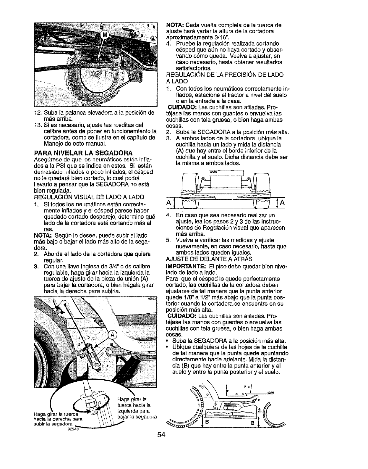
t2. Suba la patanca elevadora a la posici6n de
m#.s arribao
13. Si es necesario, ajuste las rueditas del
calibre antes de poner en funcionamiento la
cortadora, como se ilustra en el capftuio de
Manejo de este manual.
PARA NIVELAR LA SEGADORA
AsegtJrese de que los neum,_ticos est6n infla-
dos a la PS1 que se indica en estos. Si est&n
demasiado inflados o poco inflados, el c_sped
no le quedar& bten cortado, Io cual podr_
Ilevarlo a pensar que la SEGADORA no est&
bien regulada.
REGULACION VISUAL DE LADO A LADO
1. Si todos los neum_ticos estdn correcta-
mente inflados y el c_sped parece haber
quedado cortado desparejo, determine qu_
lado de la cortadora est#=cortando m_s al
raso
NOTA-" Segt_n Io desee, puede subir el lado
m#,s bajo o bajar el lado m_.s alto de la sega-
dora,
2. Aborde el lado de la cortadora que quiera
regular.
3. Con una Ilave inglesa de 3/4" o de calibre
regulable, haga girar hacia la izquierda ta
tuerca de ajuste de la pieza de uni6n (A)
pars bajar la cortadora, o bien h_gala girar
hacia la derecha pars subirta.
Haga gtrar la
hacla _aderecha pars
sublr ]a segadora
Hags girar la
tuerca hacia la
izqulerda pars
bajar la segadora
NOTA: Cada vuelta completa de la tuerca de
ajuste har& variar la altura de la cortadora
aproximadamente 3/16'L
4_ Pruebe la regulaci6n realizada cortando
c#sped que a0n no hays cortado y obser-
vando c6mo queda. Vuelva a ajustar, en
caso necesario, hasta obtener resultados
satisfactorios.
REGULACION DE LA PRECISION DE LADO
A LADO
1. Con todos los neum,_ticos correctamente in-
flados, estacione e! tractor anivel del suelo
o en la entrada a la casa.
OUIDADO: Las cuchillas son afiladas. Pro-
t_jase las manos con guantes o envuelva las
cuchillas con tela gruesa, o bien hags ambas
cosas.
2. Subs la SEGADORA a la posici6n m_s alta.
3_ A ambos lados de la cortadora, ubique la
cuchilla hacia un lado y mida la distancia
(A) que hay entre el borde inferior de la
cuchilla y el sueloo Dicha distancia debe ser
ta misma a ambos lades.
A
4. Er_ caso que sea necesario realizar un
ajuste, lea los pasos 2 y 3 de las instruc-
clones de Regulaci6n visual que aparecen
m_s arribao
5. Vuetva a verificar las medidas y ajuste
nuevamente, en caso necesario, basts que
ambos lados queden iguales.
AJUSTE DE DELANTE A ATR/_S
IMPORTANTE" El piso debe quedar bien nive-
lado de lado a lado°
Para que el c_sped le quede perfectamente
cortado, las cuchillas de la cortadora deben
ajustarse de tal manera qua la punts anterior
quede 1/8" a 1/2" m_s abajo que la punts pos-
terior cuando la cortadorase encuentre en su
posici6n m_s alta.
CUIDADO: Las cuchillas son afiladas. Pro-
t_jase las manos con guantes o envuelva las
cuchillas con tela gruesa, o bien haga ambas
cosas.
• Subs la SEGADORA a la posici6n m_s alta.
• Ubique cualquiera de las hojas de la cuchilla
de tal manera que la punts quede apuntando
directamente hacia adelante. Mida la distan*
cia (B) que hay entre la punta anterior y el
suelo y entre la punta posterior y el suelo.
54
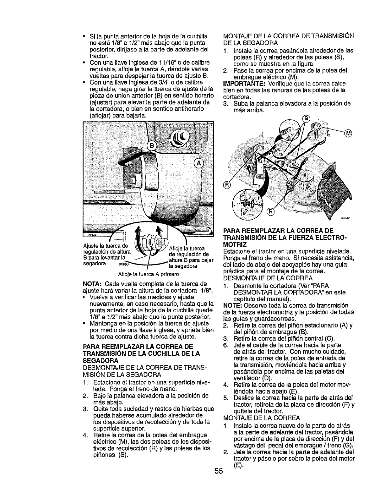
• Si la punta anterior de la hoja de la cuchiila
no estd 1/8" a 1/2" m_.s abajo qua la punta
posterior, dirfjase a la parts de adelante del
tractor.
• Con una Ilave inglesa de 11/16"o de calibre
reguiable, afloje la tuerca A, ddndole varias
vueltas para despejar la tuerca de ajuste B.
• Con una Ilave inglesa de 3/4" o de calibre
regulable, haga girar la tuerca de ajuste de la
plaza de uni6n anterior (B) en sentido horario
(ajustar) para elevar ta parts de adelante de
la cortadora, o bien en sentido antihorario
(aflojar) para bajarla.
MONTAJE DE LA CORREA DE TRANSMISI6N
DE LA SEGADORA
1. Instals la correa pasdndola alrededor de las
poleas (R) y alrededor de las poleas (S),
como se muestra en la figura
2. Pase la correa por encima de la polea del
embrague electrico (M).
IMPORTANTE, Verifique qua la correa calce
bienen todas las ranuras de lae poleas de la
cortadora.
3. Suba la palanca elevadora a la posici6n de
mds arriba.
Ajustela tuercade Aflojela tuerca
regulacf6nde altura de regulact6nde
B para ievantarla B para bajar
segadora Easegadora
Afloje ta tuerca A primero
NOTA: Cada vuelta completa de la tuerca de
ajuste hard variar la altura de la cortadora 1/8'L
° Vuelva a verificar las medidas y ajuste
nuevamente, en caso necesario, hasta qua la
punta anterior de la hoja de la cuchilla quads
1/8" a I/2" rods abajo qua la punta posterior,
° Mantenga en la posiciOn la tuerca de ajuste
por medio de una Ifave inglesa, y apriete bien
la tuerca contra dicha tuerca de ajuste.
PARA REEMPLAZAR LA CORREA DE
TRANSMISI6N DE LA CUCHILLA DE LA
SEGADORA
DESMONTAJE DE LA CORREA DE TRANS-
MISION DE LA SEGADORA
1. Estacione el tractor en una superficie nive-
lada. Ponga et freno de mano.
2. Baje la patanca elevadora a la posici6n de
mds abajo.
3. Quite toda suciedad y restos de hierbas qua
pueda haberse acumulado alrededor de
los dispositivos de recolecciOn y de toda la
superficie superior.
4. Retire la correa de la polea del embrague
el_ctrico (M), las dos poleas de los disposi-
tivos de recotecci6n (R) y lae poleae de los
pifones (S).
PARA REEMPLAZAR LA CORREA DE
TRANSMISI6N DE LA FUERZA ELECTRO-
MOTRIZ
Estacione el tractor en una superficie nivelada.
Ponga el freno de manoo Si necesita asistencia,
del lado de abajo del apoyapi6s hay una gufa
prdctica para el montaje de la correa.
DESMONTAJE DE LA CORREA
1. Desmonte la cortadora (Ver"PARA
DESMONTAR LA CORTADORA" en este
capitulo del manual).
NOTE; Observe toda la correa de transmisiOn
de la fuerza electromotriz y la posici6n de todas
las gulas y guardacorreas.
2. Retire la correa del pif6n estacionario (A) y
del pi_6n de embrague (B).
3. Retire la correa del pii_On central (C).
6. Jale el cable de la correa hacia la parte
de atrds del tractor. Con mucho cuidado,
retire la correa de la polea de entrada de
la transmisi6n, movidndola hacia arriba y
pas_.ndola por encima de las paletas del
ventilador (D).
4. Retire la correa de la polea de! motor mow
i_ndola hacia abajo (E).
5. Deslice la correa hacia la parts de atrds del
tractor, retirela de la placa de direcci6n (F) y
quitela del tractor,
MONTAJE DE LA CORREA
1. Instals la correa nueva de ta parts de atrds
a la parte de adelante del tractor, pas_.ndola
pot ancima de la placa de direcci6n (F) y del
vdstago del pedal def embrague / freno (G).
Jale la correa hacia la parta de adelante del
tractor y pdselo por sobre la polea del motor
.
55
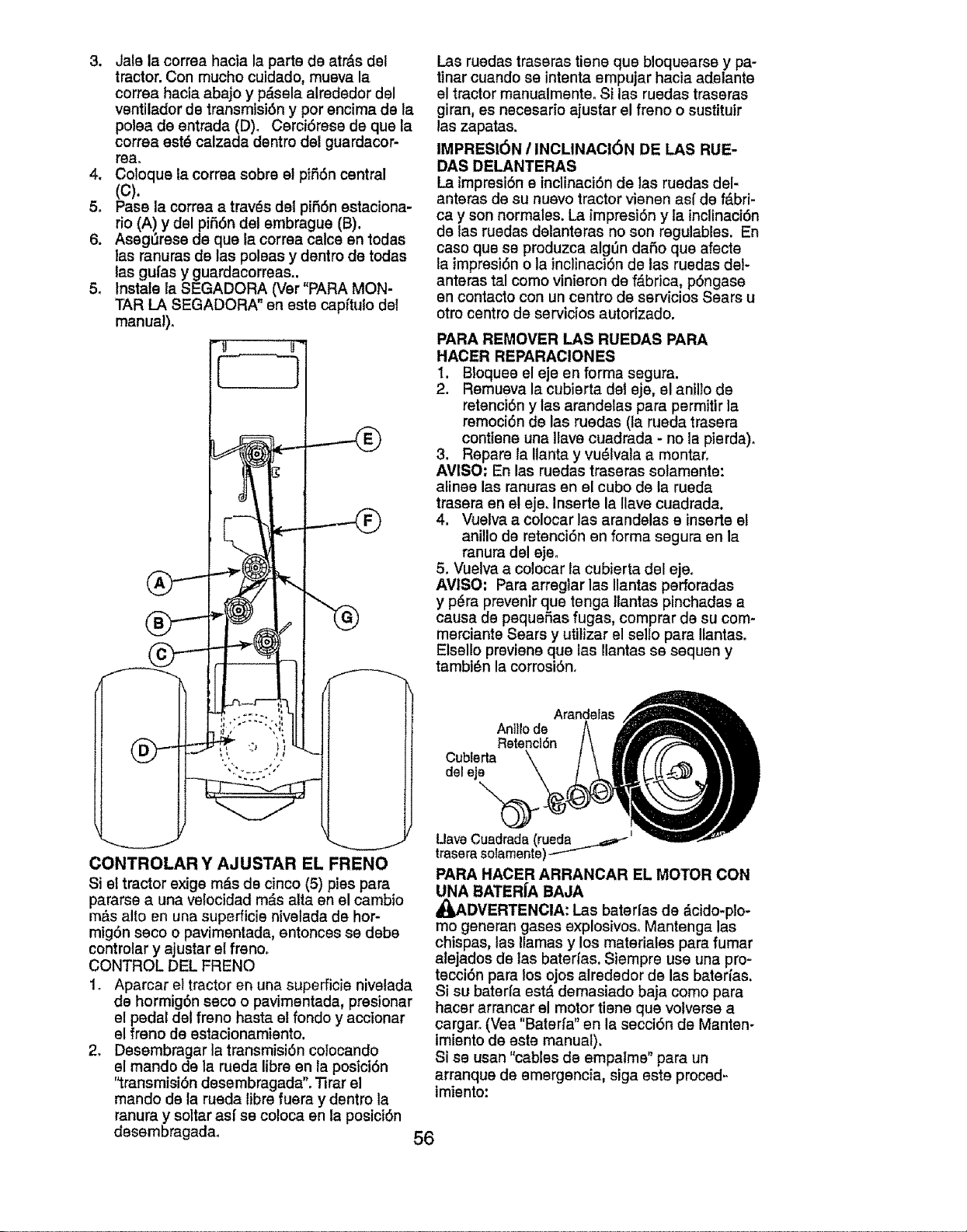
3. Jale la corraa hacia la parts de atr&s del
tractor. Con mucho cuidado, mueva la
correa hacia abajo y p_sela alrededor del
ventilador de transmisi6n y por encima de la
polea de entrada (D)o Cerci6rese de que la
correa est_ calzada dentro del guardacor-
tea.
4. Coloque la correa sobre el pi_6n central
(c).
5. Pass la corrsa a trav_s del pi_6n estaciona-
rio (A) y del pi_6n del embrague (B).
6. Asegt_rese de que la correa calce en todas
las ranuras de las poleas y dentro de todas
tas guias y guardacorreas..
5. Instafe la SEGADORA (Ver"PARA MON-
TAR LA SEGADORA" en este capftulo del
manual).
F
CONTROLAR Y AJUSTAR EL FRENO
Si et tractor exige rn_s de cinco (5) pies para
pararse a una velocidad m_s alta en el cambio
m,_s alto en una superficie nivelada de hor-
migdn seco o pavimentada, entonces se debs
controlar y ajustar el freno_
CONTROL DEL FRENO
1. Aparcar el tractor en una supefficie nivefada
de hormig6n seco o pavirnentada, presionar
el pedal del freno basts el fondo y accionar
el freno de estacionamiento.
2, Desembragar la transmisi6n colocando
el mando de la rueda libre en la posici6n
'_ransmisi6n desembragada". _rar el
mando de la rueda libre fuera y dentro la
ranura y soltar asf se coloca en la posici6n
desembragadao
Las ruedas traseras tiene que bloquearse y pa-
tinar cuando se intenta empujar hacia adelante
el tractor manualmenteo Si las ruedas traseras
giran, es necesario ajustar el freno o sustituir
las zapatas.
IMPRESi6N / INCLINACI6N DE LAS RUE-
DAS DELANTERAS
La irnpresi6n e inclinaci6n de las ruedas del-
anteras de su nuevo tractor vienen asf de f_.bri-
ca y son normales. La impresidn y ia inclinaci6n
de fas ruedas delanteras no son regulables. En
caso que se produzca alg_n dafio que afecte
la impresi6n o la inclinaci6n de las ruedas del-
anteras tal como vinieron de f_.brica, p6ngase
en contacto con un centro de servicios Sears u
otro centro de servicios autorizado.
PARA REMOVER LAS RUEDAS PAPA
HACER REPARACIONES
I. BIoquee el eje en forma segura.
2. Remueva la cubierta del eje, el anilio de
retenci6n y lae arandelas para permitir la
remoci6n de las ruedas (la rueda trasera
contiene una Ilave cuadrada - no la pierda).
3. Repare la Ilanta y vu_lvala a montar.
AVlSO: En las ruedas traseras solamente:
alines las ranuras en el cubo de la rueda
trasera en el ejeo Inserte la Ilave cuadrada.
4, Vuelva a colocar las arandelas e inserts e!
anitlo de retenci6n en forma segura en la
ranura del ejeo
5. Vuelva a colocar la cubierta del eje.
AVlSO: Para arreg}ar las Ilantas perforadas
y p_ra prevenir que tenga Itantas pinchadas a
causa de pequefias fugas, comprar de su com-
merciante Sears y utilizar el sello pars Ilantas.
Etsello previene que las Ilantas se sequen y
tambi6n la corrosi6n.
Arandelas
An]llo de
Retencl6n
Cublerta
del eje
UaveCuadrada (rueda
traserasolamente)
PARA HACER ARRANOAR EL MOTOR CON
UNA BATERfA BAJA
_DVERTENCIA: I_as baterias de dcido-plo-
rno generan gases explosivos_ Mantenga las
chispas, las llamas y los materiafes para fumar
alejados de las baterfas. Siempre use una pro-
tecci6n pars los ojos alrededor de las baterfas.
Si su baterfa est_ demasiado baja como para
hacer arrancar el motor tiene que votverse a
cargaro (Vea "Baterfa" en la secci6n de Manten-
tmiento de este manual).
Si se usan "cables de empalme" pars un
arranque de emergencia, siga este proced-
imiento:
56
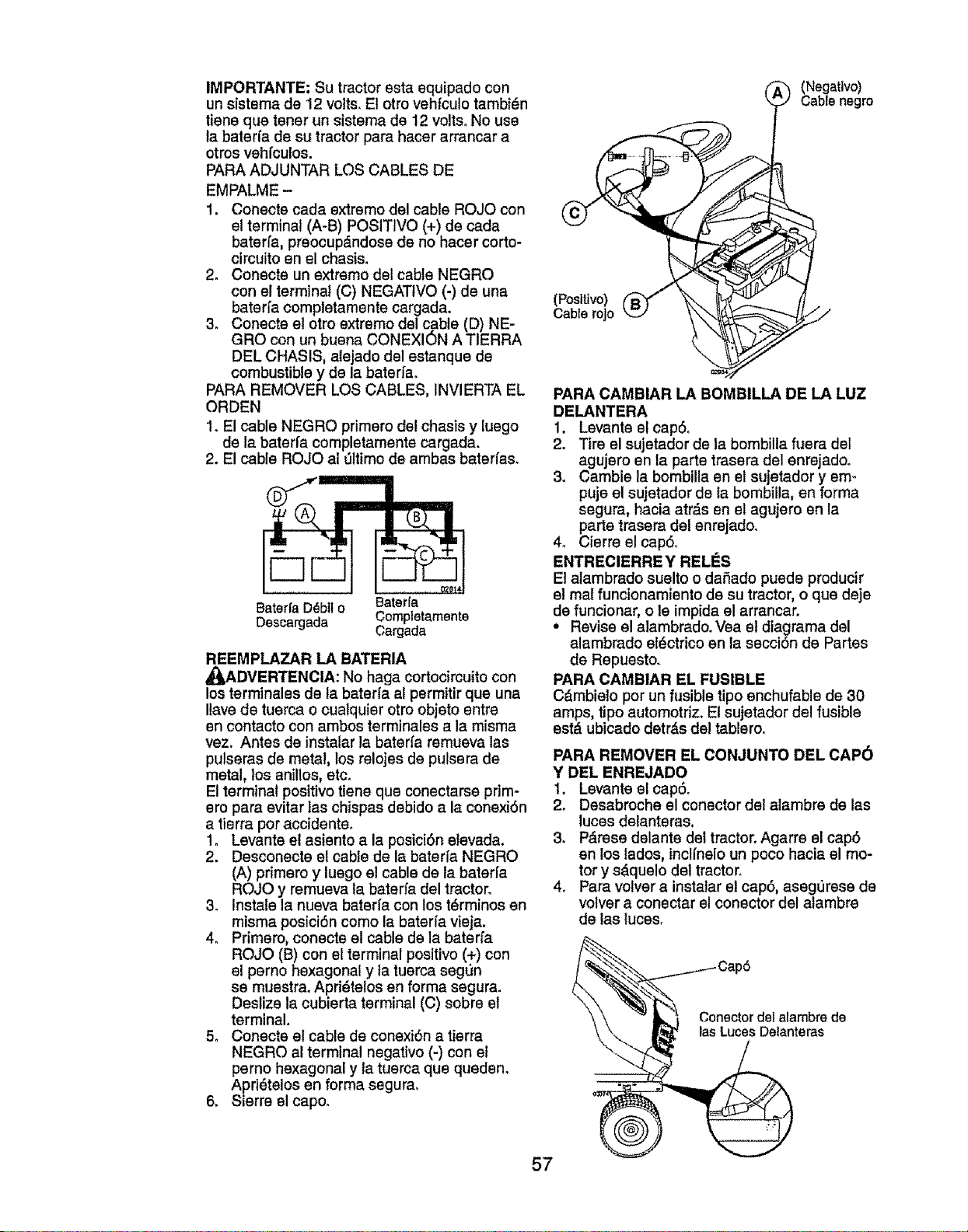
IMPORTANTE: Su tractor esta equipado con
un sistema de 12 volts. E1otro vehfculo tambidn
tiene que tener un sistema de 12 volts° No use
la baterfa de su tractor para hacer arrancar a
otros vehfculos.
PARA ADJUNTAR LOS CABLES DE
EMPALME -
1. Conecte cada extremo del cable ROJO con
el terminal (A-B) POSITIVO (+) de cada
baterfa, preocupdndose de no hacer corto-
circuito en el chasis.
2. Conecte un extremo del cable NEGRO
con el terminal (C) NEGATIVO (-) de una
baterfa completamente cargada.
3. Conecte el otro extremo del cable (D) NE-
GRO con un buena CONEXI6N A TIERRA
DEL CHASIS, alejado del estanque de
combustible y de la baterfa.
PARA REMOVER LOS CABLES, INVIERTA EL
ORDEN
1. El cable NEGRO primero del chasis y luego
de la bater[a completamente cargada.
2. El cable ROJO al _31timode ambas baterfas.
Bateda D_bU o
Descargada
Baterfa
Completamente
Cargada
REEMPLAZAR LA BATERIA
_DVERTENCIA: No haga cortocircuito con
los terminales de ta bater[a al permitir que una
Ilave de tuerca o cualquier otro objeto entre
en contacto con ambos terminales a la misma
vez. Antes de instalar la baterfa remueva las
pulseras de metal, los relojes de pulsera de
metal, los anillos, etc_
El terminal positivo tiene que conectarse prim-
ero para evitar las chispas debido a la conexi6n
a tierra pot accidente.
1o Levante el asiento a la posici6n elevada.
2. Desconecte el cable de la baterla NEGRO
(A) primero y luego e! cable de la baterfa
ROJO y remueva la baterfa del tractor.
3. Instale la nueva baterfa con los t_rminos en
miema posici6n como la baterla vieja.
4_ Primero, conecte el cable de la baterfa
ROJO (B) con el terminal positivo (+) con
el pemo hexagonal y ta tuerca seg_n
se muestra. Apri_telos en forma segura.
Deslize la cubierta terminal (C) sobre el
terminal.
5o Conecte el cable de conexi6n a tierra
NEGRO al terminal negativo (-) con el
perno hexagonal y la tuerca que queden.
Apri_telos en forma segurao
6. Sierre el cape.
(Positivo)
Cable roJo
_ (Negatlvo)
Cable negro
5/
PARA CAMBIAR LA BOMBILLA DE LA LUZ
DELANTERA
1. Levante el cap6.
2. Tire el sujetador de la bombilla fuera del
agujero en la parte trasera del enrejadoo
3. Camble la bombilla en el sujetador y em_
puje el sujetador de la bombilla, en forma
segura, hacia atrds en el agujero en la
parte trasera del enrejado.
4_ Cierre el cap6o
ENTREClERRE Y RELES
Et atambrado suelto o dafiado puede producir
el real funcionamiento de su tractor, o que deje
de funcionar, o le impida el arrancar.
• Revise el alambrado. Vea el diagrama del
alambrado eldctrico en ta secci6n de Partes
de Repuesto.
PARA CAMBIAR EL FUSIBLE
Cdmbielo por un fusible tipo enchufable de 30
amps, tipo automotriz. E! sujetador del fusible
estd ubicado detr&s del tablero.
PARA REMOVER EL CONJUNTO DEL CAP6
Y DEL ENREJADO
1. Levante el cap6o
2. Desabroche el conector del alambre de las
luces delanteras.
3. P&rese delante del tractor. Agarre el cap6
en los tados, inclfnelo un poco hacia el mo-
tor y sdquelo del tractor°
4. Para volver a instatar el cap6, asegOrese de
volver a conectar el conector del alambre
de las luces.
57
_. _ Cap6
___ onectordelalambre de
lasLuces Delanteras
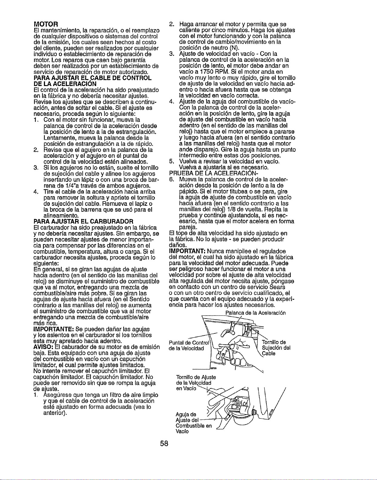
MOTOR
El mantenimiento, la reparaci6n, o el reemplazo
de cualquier dispositivos o sistemas del control
de la emisi6n, los cuales seen hechos al costo
del cliente, pueden ser realizados por cualquier
individuo o establecimiento de reparaciSn de
motor. Los reparos qua caen bajo garantfa
deben ser realizados por un establecimiento de
servicio de reparaci6n de motor autorizado.
PARA AJUSTAR EL CABLE DE CONTROL
DE LA ACELERACI6N
El control de la aceleraci6n ha sido preajustado
en la f_,brica y no deberfa necesitar ajustes°
Revise los ajustes que se describen a continu-
aci6n, antes de soltar el cable. Si el ajuste es
necesario, proceda seg0n Io siguiente:
1. Con el motor sin funcionar, mueva la
_aalancade control de la aceteraciSn desde
posiciSn de lento ala de estrangulacion.
Lentamente, mueva la palanca desde la
posici6n de estrangulaciSn ala de r_pido.
2. Revise qua el agujero en la palanca de la
aceleraci6n y el agujero en el puntal de
control de la velocidad est_n alineados.
3. S| los agujeros no Io est_n, suelte el tornillo
de sujecion del cable y alinee los agujeros
insertando un t_piz o con una broca de bar-
rena de 1/4"a tray, s de ambos agujeros.
4. Tire el cable de la aceleraciSn hacia arriba
para remover la soltura y apriete el tornillo
de sujeciSn del cab}e. Remueva et lapiz o
la broca de la barrena que se us5 pare el
alineamiento.
PARA AJUSTAR EL CARBURADOR
El carburador ha sido preajustado en la f_brica
y no deberfa necesitar ajuste& Sin embargo, se
pueden necesitar ajustes de menor importan-
cia para compensar por las diferencias en el
combustible, temperatura, altura o carga_ Si el
carburaclor necesita ajustes, proceda segun Io
siguiente:
En _eneral, si se giran las agujas de ajuste
hacla adentro (en el sentido de las manillas del
reloj) se disminuye el suministro de combustible
qua vaal motor, entregando una mezcla de
combustible/aire m&s pobre. Si se giran lee
agujas de ajuste hacia afuera (an el Sentido
contrario a lee manillas del reloj) se aumenta
el suministro de combustible qua vaal motor
entregando una mezcla de combustible/aire
m(_snca.
IMPORTANTE: Se pueden daSar las aguias
y los asientos en el carburador si los tornlllos
esta muyapretado hacia adentro.
AVISO: El caburador de su motor es de emisi6n
baja. Esta equipado con una aguja de ajuste
del combustible en vacfo con un capuchSn
limitador, el cual permite ajustes limitado&
No intente remover et capuchSn limitador. El
capuch6n limitadoro El capuchSn limitador. No
puede ser removido sin qua se rompa la aguja
de ejuste.
1. Asegt_rese que tenga un fittro de aire limpio
y qua el cable de control de la aceleraciSn
est_ ajustedo en forma adecuada (yea Io
anterior).
2. Haga arrancar el motor y permita que se
caliente por cinco minutos. Haga los ajustes
con el motor funcionando y con la palanca
de control de cambioimovlmiento en la
posici6n de neutro (N).
3. Ajuste de velocidad en vacfo - Con fa
palanca de control de la aceleraciSn en la
posici6n de lento, el motor debe andar en
vacfo a 1750 RPM. Si el motor anda en
vacfo muy lento o muy r_pido, gire el tornillo
de ajuste de la velocidad en vacfo hacia ad-
entro o hacia afuera hasta qua se obtenga
la velocidad en vacfo correct&
4o ,_juste de la aguja del combustible de vacfo-
Con la palanca de control de la aceler-
aci6n en la posiciSn de lento, gire la aguja
de ajuste de! combustible en vacfo hacia
adentro (an el sentido de tas manillas del
reloj) haste que el motor empiece a pararse
y luego hacia afuera (en e! sentido contrario
alas manillas de! reloj) hasta qua el motor
ande disparejo. Gire la aguja haste un punto
intermedio entre estas doe posiciones.
5. Vuelva a reviser la velocidad en vacfo.
Vuelva a ajustarla si es nec,esario.
PRUEBA DE LA ACELERACION-
6. Mueva la palanca de control de la aceler-
aciSn desde la posici6n de lento ala de
p_.pido. St el motor titubea o se pare, gire
la aguja de ajuste de combustible en vacfo
hacia afuera (en el sentido contrario a las
mani!las del relo.j) 1/8 de vuelta. Repita la
prueba y continue ajustandola, si es nec-
esario, hasta que el motor acelera en forma
pareja.
El tope de alta velocidad ha sido ajustado en
la f&brlca. No Io ajuste - se pueden producir
daSos.
IMPORTANT; Nunca manipilee el reguladoe
det motor, el cual ha sido ajustado en la f&brica
pare la velocidad del motor adecuada° Puede
set peligroso hacer funcionar el motor a una
veloctdad por sobre el ajuste de alta velocidad
alta regutada del motor necsita ajuste,pSngase
en contacto Con un centro de servicio Sears
o con un otto centro de servicio cualificado, el
qua cuenta con el equipo adecuado y la experi-
encia pare hacer los ajustes necesarios.
Palancade la AceleraciSn
Puntalde Control
de laVelocidad
SujeclSn del
Oable
Tornfllode Ajuste
de la Veloctdad
o°wo,o.
Ajustedel _/_/'
Combustibleen __/
Vaclo
58
lnmediatamente prepare su tractor para el
almacenamiento al final de la temporada o si el
tractor no se va a usar pot 30 dfas o m_ts.
JqlbADVERTENClA: Nunca almacene el trac-
tor con gasolina en el estanque dentro de un
edificio en donde los gases pueden aicanzar
una llama expuesta o una chispa. Permita que
el motor se enfrfe antes de almacenado en
cualquier recinto privado.
TRACTOR
Cuando el tractor se va a almacenar por cierto
perfodo de tiempo, lfmpiela cuidadosamente,
quite toda la mugre, la grasa, las hojas, etco
Gudrdela en una _rea limpia y eeca.
1. Limpie todo el tractor (vea "LIMPIEZA" en la
secciOn de Mantenimiento en este manual).
2. tnspeccione y cambie las correas, si es
necesario (vea las instrucciones para el
cambio de las correas en la secciOn de
Servicio y Ajustes de este manual).
3. Lubrfquelo, segt)n se muestra en la secciOn
de Mantenimiento de este manual.
4. Asegerese que todas las tuercas, los
pernos y los tornillos est_n sujetados
en forma segura. Inspeccione tas partes
movibles para verificar si hay daOo, rotura o
desgaste. C_mbielas si es necesario.
5. Retoque todas superficies pintadas oxida-
das o picadas; aplique lija antes de pintar.
BATER|A
, Cargue la baterfa completamente antes de
guardarla.
° Despuds de cierto periodo de tiempo en
almacenamiento, la baterfa puede necesitar
volver a cargarse.
, Para ayudar a evitar la corrosion y las fugas
de potencia durante largos perfodos de
almacenamiento, se deben desconectar
los cables de la bateda y se debe limpiar
cuidadosamente (vea "PARA LIMPIAR LA
BATER1AY LOS TERMINALES en la sec-
ciOn de Mantenimientode este manual).
• Despu_s de limpiarla, deje los cables desco-
nectados y p0ngalos en donde no puedan
entrar en contacto con los terminales de la
baterfa.
• Si se remueve la baterfa del tractor para el
almacenamiento, no la guarde directamente
sobre concreto o sobre superficies ht_medas.
MOTOR
SISTEMA DE COMBUSTIBLE
IMPORTANTE: Es important evitar que se
forman depositos de goma en partes funda-
mentales del sistema de combus-tible tales
como el carburador, el filtro del combustible,
la manguera del combustibles mezclados con
alcohol (conocido como gasohol o que tlenen
etanol o metanot) pueden atraer humedad, !o
_ue conduce a la separaciOn y a la formaciOn
e acudos durante elalmacenamiento. La
gasolina acidica puede daff_arel sistema de
combustible de un motor durante et periodo de
almacenamiento.
° Vaciar el depOsito del carburante poniendo
en marcha el motor y dej_.ndolo funcionar
hasta que et carburante termine el carbura-
dor est_ vacfoo
° Nunca use los productos para limpieza del
carburador o de! motor en el estanque de
combustible pues se pueden producir dafos
permanentes.
• Use combustible nuevo la prOxima
temporada.
AMISO: El estabilizador de combustible es una
alternaUva aceptable para reducir a un mfnimo
la formaciOn de depOsitos de goma en el com-
bustible durante el perfodo de almacenamiento.
Agregue estabilizador a la gasolina en el
estanque de combustible o en el envase para el
almacenamiento. Siempre siga la proporci0n de
mezcla que se encuentra en el envase del esta-
bilizador. Haga funcionar el motor por Io menos
10 minutos despu_s de agregar el estabilizador,
para permitir que _.ste Ilegue al carburador. No
vaciar la gasolina del estanque de gasolina y el
carburador sise est& usando estabilizador de
combustible.
ACEITE DEL MOTOR
Drone el aceite (con el motor caliente) y
cd.mbielo con aceite de motor limpio. (Yea "MO-
TOR" en la secciOn de Mantenimiento" de este
manual,)
CILINDRO(8)
1o Remueva la(s) bujfa(s).
2. Vacie una onza de aceite a trav_s del
agujero(s) de la bujfa en el cilindro(s).
3. Gire la Ilave de ignici0n a la posiciOn de "Ar-
ranque" (Start), por unos cuantos segundos
para distribuir el aceite.
4. Cambie pot bujfa(s) nueva(s).
OTROS
° No guarde la gasolina de una temporada a la
otra.
° Cambie el envase de la gasolina si se emp-
ieza a oxidar. La oxidaci0n y/o la mugre en
su gasolina producir_.n probiemas.
° Si es posible, guarde su unidad en un recinto
cerrado y ct)brala para protegerla contra el
polvo y la mugreo
° Cubra su unidad con un forro protector
adecuado que no retenga la humedad. No
use pl_stico. El pl_stico no puede respirar, 1o
que permite la formaciOn de condensaci0n,
Io que producir_, la oxidaci0n de su unidad.
IMPORTANTE: Nunca cubra el tractor mientras
el motor y las areas de escape todavia estan
calientes.
59
IDENTIFICACi6N DE PROBLEMAS:
Vea Is seccl6n aproplada en el manual a menos que est_ dirlgldo a un centro de servlclo
Sears.
PROBLEMA CORRECCI6N
No arranca
CAUSA
1. Sin combustible,
2. ,Motor sin la
ESTRANGULACI6N" (CHOKE)
adecuada,
3. Motor ahogadoo
, Bujfa mala_
• Baterfa baja o descargada
6. Filtro de aire sucio.
7, Filtro de combustible sucio,
8, Agua en el combustible.
D|ffcil de arrancar
El motor no da
vuelta
E! motor suena
_ero noarranca
P_rdida de fuerza
9. Alambrado suelto o daSado°
10.Carburador desajustado.
11oV_lvulae del motor
desajustadas.
1. Filtro de aire sucio,
2. Bujfa mala.
3. Baterfa baja o descargadao
4. Filtro de combustible sucioo
5. Combustible rancio o sucio.
6, Alambrado suelto o daSado,
7, Carburador desajustadoo
8, V_lvulasdel motor desajustadas,
1. Pedal del freno no presionado.
2, El embrague del accesorio est_
enganchado.
3. Baterfa baja o descargada.
4. Fusible quemado.
5< Terminales de la bateria corroidos
6. Alambrado suelto o daSado.
7. Interruptor de la ignici6n fallado.
8. Solenoide o arrancador falladoso
°
Interruptor(es) qua exige(n) Is
presencia del operador fallado,
1, Baterla baja o descargada
2, Terminates de la baterfa corroidos,
3. Interruptor de la igniciSn
4o Solenoide o arrancador fallados.
1, Corta mucho c_sped, rnuy r_,pido
2. Aceleraci6n en la posici6n de
"ESTRANGULACION" (CHOKE).
1. Llene el estanque de combustible.
2. Vea "PARA ARRANCAR EL
MOTOR" en la secci6n de
operaci6n.
3. Espere varios minutos antes de
tratar de arrancar,
4. Cambie la bujfa.
5. Vuelva a cargar o cambie la baterfa,
6 Limpie!cambie el filtro de aireo
7, Cambie el filtro de combustible.
8. Vaciar el estanque de combustible
y el carburador, vuelva a Ilenar el
estanque con gasolina nueva
cambie cambie el filtro de combus-
tible.
9. Revise todo el alambrado.
10.Vea "Paraajustar el Carburador"
en la secci6n de Servicio y Ajustes.
11.Pongase en contacto con un
centro de servicio Sears o con un
otro centro de servicio cualificado_
. Limpie/cambie el filtro de aire.
• Cambie la bujfa,
3. Vuelva a cargar o cambie la baterfa,
4 Cambie el filtro de combustible.
5. Vaciar el estanque de combustible
y vuelva a Ilenarlo con gasolina
nuava.
6. Revise todo el alambrado.
7. Vea "Para ajustar el Carburador"
en la secci6a de Servicio y Ajustes.
8. Pongase en contacto con un
centro de servicio Sears o con un
otro centro de servicio cualificado.
1. Preeione el pedal del freno.
2. Desenganche el embrague del
accesorio,
3. Vuelva a cargar o cambie la baterfa
4, Cambie el fusible.
. Limpie los tarminales de la baterfa,
• Revise todo el alambrado.
7. Revise/cambie el interrupter de la
igniciSn.
8. Revise/cambie el solenoide o
arrancador.
9. PSngase en contacto con un
centro de servicio Sears o con un
otro centro de servicio cualificado,
t. Vuelva a cargar o cambie la baterfa.
2o Limpie los terminatesde la bateria
3. Revise todo el alambrado.
4, Revise/cambie el solenoide o
arrancador.
t, Eleve la altura de corte•
2. Ajuste el control de la aceleraciSn,
6O
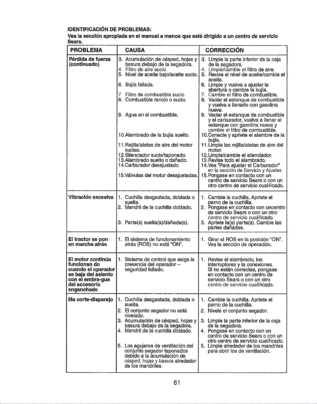
IDENT|FICACI6N DE PROBLEMAS:
Vea la seccl6n aproplada en el manual a menos que estd dlrlgldo a un centro de serviclo
Pdrdida de fuerza
(contlnuado)
Sears.
PROBLEMA CAUSA CORRECCI6N
3. Acumulaci6n de c_sped, hojas y
basura debajo de la segadora,
4 Fiftro de airs sucio.
5o Nivel de aceite bajoiaceite sucio.
6. Bujfa fallada.
7, Filtro de combustible sucio.
8. Combustible rancio o sucio,
Vlbract6n exceslva
9. Agua en el combustible.
El motor contlnda
funclonan do
cuando el operador
se baja dei aslento
con el embra-gue
del accesorlo
enganchado
t0.Alambrado de ta bujia suelto,
11oRejillaJaletas de aire del motor
sucias.
12,Silenciador sucio/taponado.
13,Alambrado suelto o daSadoo
14,Carburador desajustado.
15,V_.lvulas del motor desajustadas,
1. Cuchilia desgastada, doblada o
suelta.
2. Mandril de la cuchilla doblado.
3. Limpie la parts inferior de la caja
de la segadorao
4. Limpie/cambie el filtro de aireo
5, Revise el nivel de aceite/cambie el
aceite.
6. Limpie y vuelva a ajustar la
abertura o cambie la bujfa.
7. Cambie el filtro de combustible,
8. Vaciar el estanque de combustible
y vuelva a llenarlo con gasolina
nueva,
9. Vaciar el estanque de combustible
y el earburador, vuefva a llenar el
estanque con gasotina nueva y
cambie el filtro de combustible.
10.Conecte y apriete el alambre de la
buji'a,
11.Limpie las rejilla/aletas de airs del
motor.
12.Limpie/cambie el silenciador.
13rRevise todo el alambrado.
14,Vea "Para ajustar el Carburador"
en ta secci6n de Servicio y Ajustes.
15.Pongase en contacto con un
centro de servicio Sears o con un
otro centro de sarvicio cualificado.
2o
3. Parts(s) suelta(s)/daSada(s). 3,
El tractor se pon 1. El sistema de funcionamiento 1, Girar el ROSen la posici6n "ON".
en marcha atr_s atrds (ROS) no est_ "ON", Vea la secci6n de operaci6n.
1o
1. Sistema de control qua exige la
pressncia del operador-
seguridad fallado.
1. Cuchilla desgastada, dobtada o
suelta,
2. El conjunto segador no est,.
nivelado.
3_ Acumulaci6n de c_sped, hojas y
basura debajo de la segadora.
4o Mandril de la cuchilla dobladoo
Los agujeros de ventilaci6n del
conjunto segador taponados
debido a la acumulaci6n de
c_sped, hojas y basura alredsdor
de los mandrilas,
Ma corte-dlspareJo
5_
Cambie la cuchtlla,Apriete el
_erno de la cuchilla.
ngase en contacto con uncentro
de servicio Sears o con un otro
centro de servicio cualificadoo
Apriete la(s) parts(s). Cambie las
partes daSadas.
Revise el alambrado, los
interruptores y la conexiones.
Si no estdn correctas, pongase
en contacto con un centro de
servicio Sears o con un otto
centro de servicio cualificado.
2.
3.
4.
.
Cambie la cuchilla. Apriste e!
perno de la cuchilla,
Nivele el conjunto segadoro
Limpie la parts inferior de la caja
de la segadora.
Pongase en contacto con un
centro de servicio Sears o con un
otro centro de servicio cualificado,
Limpie alrededor de los mandriles
para abrir los de ventilaci6n.
61
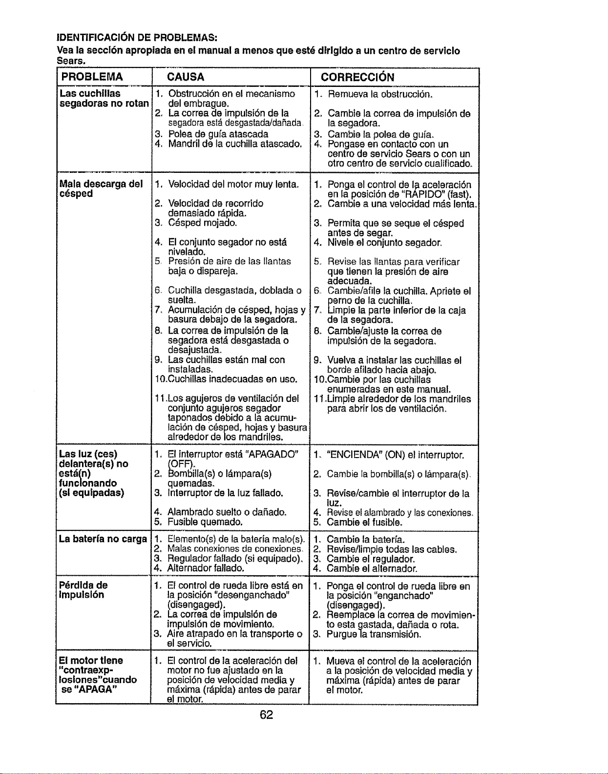
IDENTIFICACI6N DE PROBLEMAS:
Vea la seccl6n aproptada en el manual a menos que estd dtrlgldo a un centro de servtclo
Sears.
PROBLEMA
Las cuchillas
segadoras no rotan
Mala descarga del
cdsped
Las luz (ces)
dslantera(s) no
estd(n)
funclonando
(sl equlpadas)
La baterfa no carga
P_rdlda de
Impulsl6n
El motor tlene
"contraexp-
Iosiones"cuando
se "APAGA"
CAUSA
1. Obstrucci6n en el mecanismo
dsl embragueo
2= La correa de impulsi6n de la
segadora est#.desgastada/daflada.
3. Polea de gufa atascada
4. Mandril de la cuchilla ataecado.
1. Velocidad del motor muy lenta.
2. Ve!ocidad de recorrido
demasiado r,_pidao
3. C_sped mojado.
4. El conjunto segador no est,.
nivelado.
5. Presi6n de aire de las Ilantas
baja o dispareja.
6. Cuchilla desgastada, doblada o
suelta.
7. Acumulaci6n de c_sped, hojas y
basura debajo de la segadora.
8o La correa de impulsi6n de ta
segadora est_ desgastada o
desajustada_
9. Las cuchillas estd.n mal con
instaladaso
10oCuchillas inadecuadas en uso.
t 1.Los agujeros de vsntitaci6n del
conjunto agujeros segador
taponados debido a la acumu-
laci6n de cdspsd, hojas y basura
alrededor de los mandriles.
. El interruptor est#. "APAGADO"
OFF).
_ombilla(s) o !_mpara(s)
quemadas.
3. lnterruptor de la luz fallado.
4. Alambrado suelto o dafiado.
5, Fusible quemado.
1_ Elemento(s) de la baterla malo(s).
Malas conexiones de conexiones.
. Regulador fallado (si equipado).
. Afternador fallado.
1. El control de rueda librs estd en
la posici6n "desenganchado"
(disengaged).
2, La correa de impulei6n de
impulsi6n de movimiento.
3. Aire atrapado en la transports o
el servicio.
El control de la aceleraciSn del
motor no fue ajustado en la
posici6n de velocidad media y
m_xima (r_.pida) antes de parar
el motor.
CORRECCION
1. Remueva la obstrucci6m
2. Cambie la correa de impulsi6n de
la segadora.
3. Cambie la polea de gufa.
4. Pongase sn contacto con un
centro de servicio Sears o con un
otro centro de servicio cualificado.
1. Ponga el control de I_ aceleraci6n
en la posici6n de "RAPIDO" (fast).
2o Cambia a una velocidad mds lenta.
3. Permita qua ee seque el c_sped
antes de segaro
4. Nivsle el conjunto segador.
5. Revise las flantas para verificar
qua tisnen la presidn de aire
adecuada.
6 Cambie/afile la cuchilla. Apriete el
perno de la cuchilla.
7o Limpie la parts inferior de la caja
de la segadora.
8. Cambieiajuste la correa de
impufsi6n de la segadora.
9. Vuelva a instalar las cuchillas el
borde afilado hacia abajo.
lO.Cambie por las cuchillas
enumeradae en este manual.
11Mmpie alrededor de los mandriles
para abrir los de ventilaci6n.
1. "ENCIENDA" (ON) el interruptor.
2. Cambie la bombilla(s) o I&mpara(s).
3. Revise/cambie el interruptor de la
tuz.
4. Revise el alambrado y las conexioneso
5. Cambie et fusible.
1. Cambie la baterfa.
2. Reviseilimpie todas las cables.
3_ Cambie el regulador.
4. Cambie el alternador.
1. Ponga el control de rueda libra en
la posici6n "enganchado"
(disengaged).
2. Reemplace la correa de movimien-
to esta gastada, dafiada o rota.
3. Purgue la transmisi6n.
1. Mueva el control de la aceleraci6n
a la posici6n de velocidad media y
mdxima (rdpida) antes de parar
el motor.
62
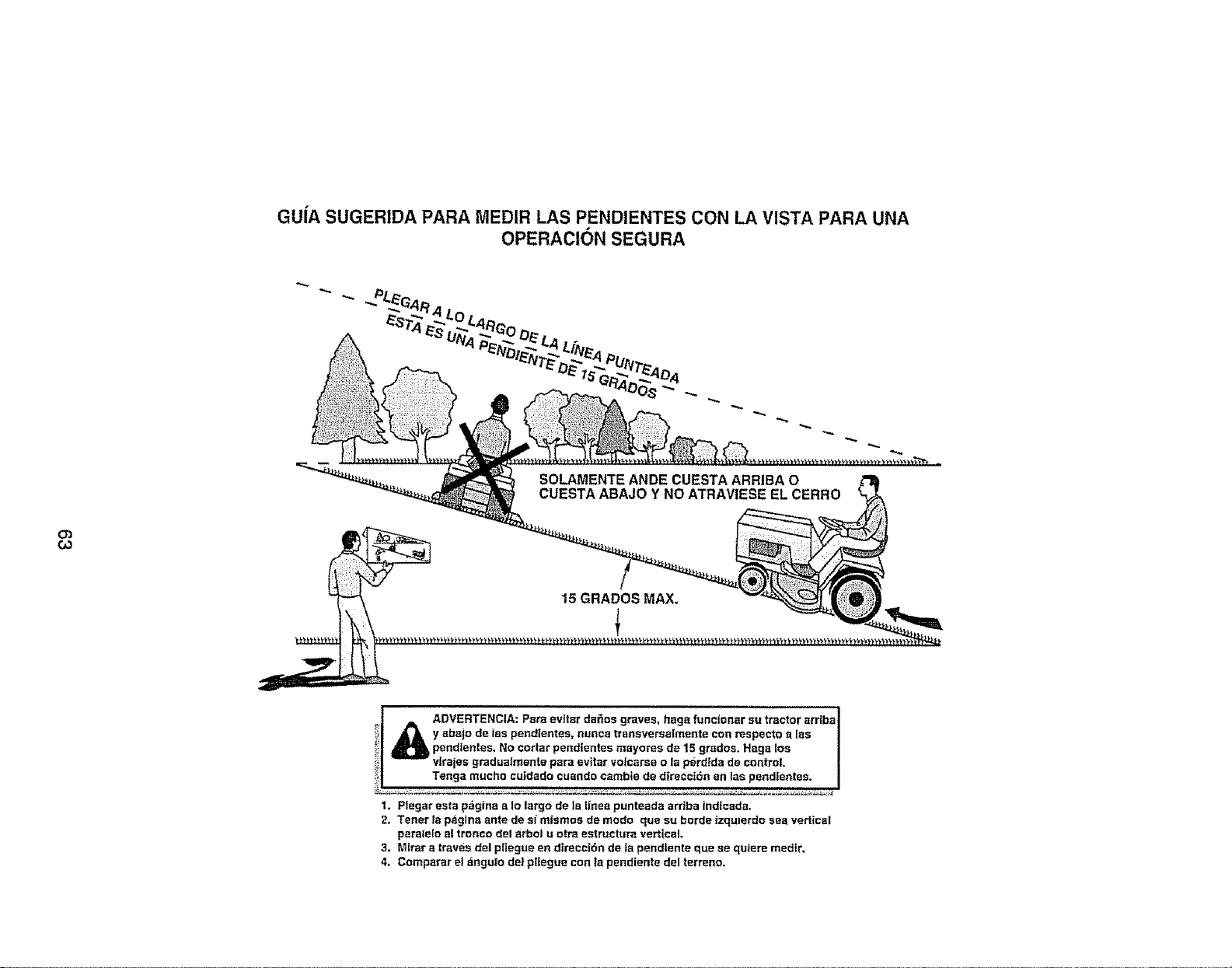
GU|A SUGERIDA PARA MEDIR LAS PENDIENTES CON LA VISTA PARA UNA
OPERACION SEGURA
03
GO
SOLAMENTE ANDE CUESTA ARRIBA O
CUESTA ABAJO Y NO ATRAVIESE EL CERRO
15 GRADOS MAX.
l
!
ADVERTENCIA: evttar da_os graves, haga functonar su tractor arriba I
Pars
y sbajo de tas pendientes, nunca transversalmente con respecto alas I
pendlentes, No eortar pendlentes mayores de 15 grados. Hags los I
viraias gradualmente para evitar volcarse o la perdlda de control, J
Tenga mucho cuidado cuando eatable de direcct6n en las pend|entes. I
1, Ptegar esta pagina a Io largo de la lines punteada arrtba indlcada,
2. Tenet la psgtna ante de si"m|smos de modo que su horde izqulerdo sea vertical
paralelo al tronco del arbol u otra estructura vertical.
3, Mirar a traves del pliegue en dtrecei6n de la pendtente que se qutere medtr,
4. Comparar el _ngulo de! pttegue con la pendiente del terreno,

Get it f
, at your home or ours!
Your Home
For repair - in your home - of all major brand appliances,
lawn and garden equipment, or heating and cooling systems,
no matter who made it, no matter who sold itl
For the re placement parts, accessories and
owner's manuals that you need to do-it-yourself.
For Sears professional installation of home appliances
and items like garage door openers and water heaters.
1-800-4-MY-HOME ® Anytime, day or night
(1-800-469-4663) [UoS,A_and Canada)
www.sears,com www,sears.ca
i_!!i_i
!i: _!
Our Home •
For repair of carry-in products like vacuums, lawn equipment,
and electronics, call or go on-line for the nearest _
Sears Parts and Repair Center. i
1-800-488-1222 Anytime, day or night (US A. only)
www.sears.com
To purchase a protection agreement (U .S.A.)
or maintenance agreement (Canada) on a product serviced by Sears:
1-800-827-6655 (USA) 1-800-361-6665 (Canada)
Para pedir servicio de reparaci6n
a domicilio, y para ordenar piezas:
t-888-SU-HOGAR _
(1-888-7_27)
© Sears Brar_s, LLC
Au Canada pour servic_ en frangais:
t.BOO.LE-FOYER Mc
(1-800-533-6937) :
www sears ,ca
@ Registered Trademark t T_ Trademark / s_ Service Mark of Sears Brands, LLC
® Marca Regis[rada / T_ Marca de F_brica / sMMarca de Servicie de Sears Brands, LLC
McMarque de commerce / _o Marque d_pos_e de Sears Brands, LLC
403857 Rev.1 05.24.06 TRiVB Printed in U.S.A.


