Loading ...
Loading ...
Loading ...
507295-02C Page 7 of 13mrcool.com
When converting a low NOx unit (designated by an L in
some model numbers) to propane, the NOx inserts must
be removed.
All LPG/propane gas equipment must conform to the safety
standards of the National Fire Protection Association.
For satisfactory operation, LPG/propane gas pressure
must be a minimum of 11” w.c. at the unit under full load.
Complete information regarding tank sizing for
vaporization, recommended regulator settings, and pipe
sizing is available from most regulator manufacturers and
LPG/propane gas suppliers.
Check all connections for leaks when piping is completed,
using a soapy, non-chlorine based solution. Some soaps
used for leak detection are corrosive to certain metals.
Carefully rinse piping thoroughly after completing
leak detection.
Danger of explosion. Can cause injury or product or
or other sources of ignition to check for leaks.
WARNING
the authority that has jurisdiction, black iron pipe shall
be installed at the gas valve and must extend outside
between the black iron pipe and the gas supply line.
CAUTION
Electrical Wiring
See Figure 4 and Figure 5
All wiring should be done in accordance with the National
Electrical Code, ANSI/NFPA No. 70 (latest edition);
Canadian Electrical Code Part 1, CSA C22.1 (latest
edition); or local codes where they prevail. Use wiring with
a temperature limitation of 75°C minimum. Run the 208 or
230 volt, 60 hertz electric power supply through a fused
disconnect switch to the control box of the unit and connect
as shown in the wiring diagram located on the inside of the
control access panel.
Power supply to the unit must be N.E.C. Class 1, and must
comply with all applicable codes. A fused disconnect switch
separate from all other circuits. If any of the wire supplied
with the unit must be replaced, replacement wire must be
of the type shown on the wiring diagram. Electrical wiring
must be sized to carry minimum circuit ampacity marked
on the unit. Use copper conductors only. Each unit must
be wired with a separate branch circuit and be properly
fused.
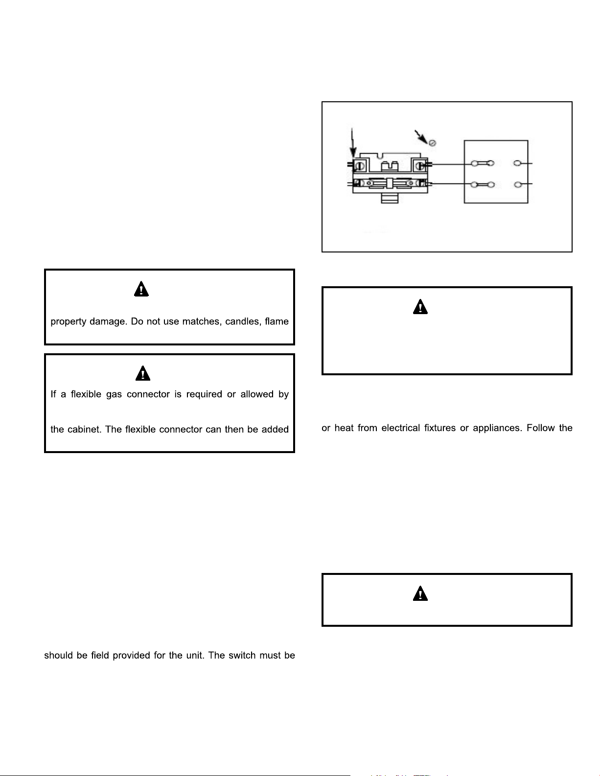
Figure 5. 208/230 Line Voltage Wiring
SINGLE PHASE
POWER SUPPLY
GROUND
LUG
CONTACTOR
FIELD-SUPPLIED FUSED
OR CIRCUIT BREAKER
DISCONNECT
If 208 Volt is supplied, transformer connection must be
changed
When connecting electrical power and control wiring
to the unit, waterproof type connectors must be used
so that water or moisture cannot be drawn into the unit
during normal operation.
CAUTION
Thermostat
The room thermostat should be located on an inside
wall where it will not be subject to drafts, sun exposure,
manufacturer’s instructions enclosed with thermostat for
general installation procedure. Color-coded insulated wires
(#18 AWG) should be used to connect the thermostat to
the unit.
Four wires are required for cooling. The heat anticipator
setting is 0.75 amp.
Compressor
Units are shipped with compressor mountings factory-
adjusted and ready for operation.
Do not loosen compressor mounting bolts.
CAUTION
Loading ...
Loading ...
Loading ...