Loading ...
Loading ...
Loading ...
LASER ADJUSTMENTS Figure 15-3
* MAKE CERTAIN the drill press is disconnected from
the power source.
• LASER LIGHT - DO NOT STARE INTO BEAM,
APERTURE or into a reflection from a mirror-like
surface.
Figure 15-1
H
ii
r>
'7 ¸ i ....
i i ----C
1. Install alignment pin (A) into chuck (B); make sure
that the pointed end (C) of the alignment pin is
down. See Figure 15-1.
Figure 15-2
D
F
E
.
.
.
g.
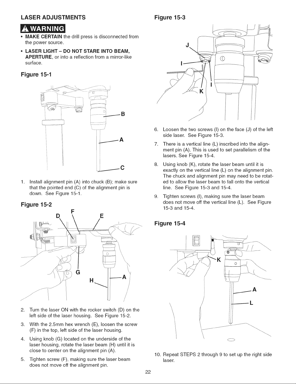
Loosen the two screws (I) on the face (J) of the left
side laser. See Figure 15-3.
There is a vertical line (L) inscribed into the align-
ment pin (A). This is used to set parallelism of the
lasers. See Figure 15-4.
Using knob (K), rotate the laser beam until it is
exactly on the vertical line (L) on the alignment pin.
The chuck and alignment pin may need to be rotat-
ed to allow the laser beam to fall onto the vertical
line. See Figure 15-3 and 15-4.
Tighten screws (I), making sure the laser beam
does not move off the vertical line (L). See Figure
15-3 and 15-4.
Figure 15-4
.
.
.
.
G
H
Turn the laser ON with the rocker switch (D) on the
left side of the laser housing. See Figure 15-2.
With the 2.5mm hex wrench (E), loosen the screw
(F) in the top, left side of the laser housing.
Using knob (G) located on the underside of the
laser housing, rotate the laser beam (H) until it is
close to center on the alignment pin (A).
Tighten screw (F), making sure the laser beam
does not move off the alignment pin.
10.
22
\
L
Repeat STEPS 2 through 9 to set up the right side
laser.
Loading ...
Loading ...
Loading ...