Operator's Manual
40v MAX* Lithium Trimmer / Edger
Model- 98020
KEY iNFORMATiON YOU SHOULD KNOW:
• The guard must be installed before trimming or edging - if not, the motor will
overheat (page 8).
• When replacing the line, use only .065 inch diameter ROUND line (Craftsman_ Model
#98030 is recommended) - otherwise the tool will not function properly (page 11).
• Do not bump the feed head against the ground - it will disrupt the feed mechanism.
• For use only with Craftsman_'40v Max* batteries.
zLCAUTION: Read, understand and follow
all Safety Rules and Operating Instructions
in this manual before using this product.
Sears Brands Management Corporation,
Hoffman Estates, IL 60179 U.S.A.
See the full line of Craftsman ®products
at craftsman.corn
Part No. 90616328 REV01
• SAFETY
• OPERATION
• MAINTENANCE
• TROUBLESHOOTING
• ESPANOL PG. 15
*Maximum initial battery pack voltage (measured
without a workload) is 40 volts. Measured under a
workload, nominal voltage is 36.
*El maximo voltaje inicial del paquete de baterias
(medido sin una carga de trabajo) es 40 voltios. Si se
mide con una carga de trabajo, el voltaje nominal es 36.
March 2015
CRAFTSMAN LiMiTED WARRANTY
FOR FOUR YEARS from the date of sale, this product is warranted against defects
in material or workmanship.
FOR TWO YEARS from the sale date, a supplied battery pack or charger is
warranted against material or workmanship defects.
WITH PROOF OF SALE, a defective product will be replaced free of charge.
For warranty coverage details to obtain free replacement, visit the web page:
www.craftsman.com/warranty
This warranty does not cover the cutting line, which is an expendable part that can
wear out from normal use within the warranty period.
This warranty is void if this product is ever used while providing commercial
services or if rented to another person.
This warranty gives you specific legal rights, and you may also have other rights
which vary from state to state.
Sears Brands Management Corporation, Hoffman Estates, tL 60179
SYMBOL SIGNAL MEANING
SAFETY ALERT SYMBOL: Indicates DANGER, WARNING, OR CAUTION.
May be used in conjunction with other symbols or pictographs.
z_ DANGER: Indicates hazardous situation which, if not avoided, will result in death or serious injury.
Z_ WARNING: Indicates hazardous situation which, if not avoided, could result in death or
serious injury.
/_ CAUTION: Indicates a hazardous situation which, if not avoided, could result in minor or
moderate injury or property damage.
IMPORTANT SAFETY WARNINGS & INSTRUCTIONS
z_WARNING: WHEN USING ELECTRIC GARDENING APPLIANCES, BASIC SAFETY
PRECAUTIONS SHOULD ALWAYS BE FOLLOWED TO REDUCE RISK OF FIRE, ELECTRIC
SHOCK, AND PERSONAL INJURY, INCLUDING THE FOLLOWING.
Read All Instructions
• ALWAYS WEAR EYE PROTECTION - Wear safety spectacles or goggles at all times when
battery is installed.
• DRESS PROPERLY - Do not wear loose clothing or jewelry. They can be caught in moving parts.
Gloves and substantial rubber soled footwear are recommended when working outdoors. Don't
operate the tool when barefoot or wearing open sandals. Wear heavy long pants to protect your
legs. Wear protective hair covering to contain long hair.
• NYLON LiNE - Keep face, hands and feet clear of rotating nylon line at all times.
• THE ROTATING LiNE PERFORMS A CUTTING FUNCTION - Use care when trimming around
screens and desirable plantings.
• KEEP ALL BYSTANDERS AWAY - at a safe distance from work area, especially children.
• MAKE SURE that other persons and pets are at least t 00 feet (30m) away.
• TO REDUCE THE RiSK of rebound (ricochet) injury, work going away from any nearby solid
object such as wall, steps, large stone, tree, etc. Use great care when working close to solid
objects and where necessary, do trimming by hand.
• AVOID ACCIDENTALLY STARTING - Don't carry with finger on trigger when battery is installed.
• USE THE RIGHT TOOL - Do not use this tool for any job except that for which it is intended.
• DON'T OVERREACH - Keep proper footing and balance at all times.
2
• DAMAGETOUNIT- Ifyoustrikeorbecomeentangledwithaforeignobject,stoptool
immediately,removebattery,checkfordamageandhaveanydamagerepairedbeforefurther
operationisattempted.Donotoperatewithabrokenhuborspool.
• REMOVEBATTERY- whennotinuse,whenreplacingline,orpriortocleaning.
• AVOIDDANGEROUSENVIRONMENTALCONDITIONS- Do
notuseelectrictoolsindamporwetlocations.FollowallinstructionsinthisInstructionManualfor
properoperationofyourtool.Don'tusethetoolintherain.
• DONOTOPERATEportableelectrictoolsingaseousorexplosiveatmospheres.Motorsinthese
toolsnormallyspark,andthesparksmightignitefumes.
• STOREIDLETOOLSINDOORS- Whennotinuse,toolsshouldbestoredindoorsinadry,
locked-upplaceoutofreachofchildren.
• STAYALERT- Donotoperatethisunitwhenyouaretired,ill,orundertheinfluenceofalcohol,
drugs,ormedication.
• MAINTAINAPPLIANCESWITHCARE- Followinstructionsinmaintenancesection.Keep
handlesdry,cleanandfreefromoilandgrease.
• CHECKDAMAGEDPARTS- Beforefurtheruseoftheappliance,aguardorotherpartthat
isdamagedshouldbecarefullycheckedtodeterminethatitwilloperateproperlyandperform
itsintendedfunction.Checkforalignmentofmovingparts,bindingofmovingparts,breakage
ofparts,mounting,andanyotherconditionthatmayaffectitsoperation.Aguardorotherpart
thatisdamagedshouldbeproperlyrepairedorreplacedbyanauthorizedservicecenterunless
otherwiseindicatedelsewhereinthismanual.
• DONOTimmersetoolinwaterorsquirtitwithahose.DONOTallowanyliquidtogetinsideit.
• DONOTstorethetoolonoradjacenttofertilizersorchemicals.
• DONOTcleanwithapressurewasher.
• Keepguardsinplaceandinworkingorder.
• Keephandsandfeetawayfromcuttingarea.
zLWARNING: Do not use tool if the switch trigger does not turn the tool on or off. Any tool that
can not be controlled with the switch trigger is dangerous and must be repaired.
zLWARNING: SOMEDUSTCREATEDBYTHiSPRODUCTCONTAINSCHEMICALSKNOWNTOTHESTATEOF
CALiFORNiATOCAUSECANCER,BIRTHDEFECTSOROTHERREPRODUCTIVEHARM.SOMEEXAMPLESOFTHESE
CHEMICALSARE:
, compounds in fertilizers
• compounds in insecticides, herbicides and pesticides
• arsenic and chromium from chemically treated lumber
To reduce your exposure to these chemicals, wear approved safety equipment such as dust masks
that are specially designed to filter out microscopic particles.
SAVE THESE INSTRUCTIONS.
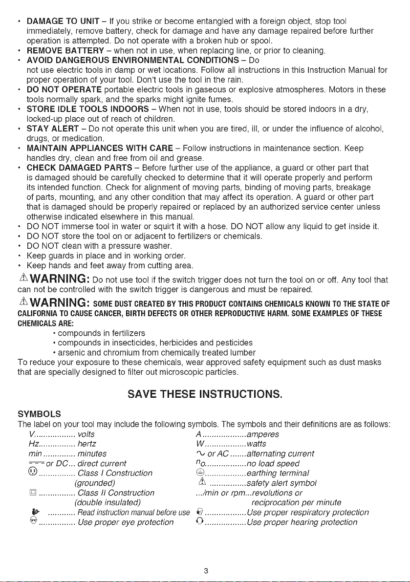
SYMBOLS
The label on your tool may include the following symbols. The symbols andtheir definitions are as follows:
V.................. volts
Hz ................ hertz
min .............. minutes
- - =or DC... direct current
_) ................ Class I Construction
(grounded)
[] ................ Class II Construction
(double insulated)
............ Read instruction manual before use
@ ................ Use proper eye protection
A ................... amperes
W .................. watts
'_ or AC ....... alternating current
no .................. no load speed
0 .................. earthing terminal
z_ ................ safety alert symbol
.../min or rpm...revotutions or
reciprocation per minute
.................. Use proper respiratory protection
0 .................. Use proper hearing protection
iMPORTANT SAFETY iNSTRUCTiONS FOR BATTERY CHARGERS
SAVE THESE INSTRUCTIONS: THiS MANUAL CONTAINS IMPORTANT SAFETY
INSTRUCTIONS FOR BATTERY CHARGERS,
• Before using charger, read all instructions and cautionary markings on charger, battery pack, and
product using battery pack.
z_WARN_NG: SHOCK HAZARD. Do not allow any liquid to get inside charger.
z_CAUTION: BURN HAZARD. To reduce the risk of injury, charge only designated Craftsman _'
batteries. Other types of batteries may burst causing personal injury and damage.
z_CAUTION: Under certain conditions, with the charger plugged in to the power supply, the
charger can be shorted by foreign material. Foreign materials of a conductive nature such as, but not
limited to, steel wool, aluminum foil, or any buildup of metallic particles should be kept away from
charger cavities. Always unplug the charger from the power supply when there is no battery pack in
the cavity. Unplug charger before attempting to clean.
_WARNING: THE CHARGER SUPPLIED WITH THIS PRODUCT tS INTENDED TO BE
PLUGGED IN SUCH THAT tT tS CORRECTLY ORIENTATED tN A VERTICAL OR FLOOR
MOUNT POSITION.
• DO NOT attempt to charge the battery pack with any chargers other than the ones in this
manual. The charger and battery pack are specifically designed to work together.
• These chargers are not intended for any uses other than charging designated Craftsman _>
rechargeable batteries. Any other uses may result in risk of fire, electric shock or electrocution.
• Do not expose charger to rain or snow.
• Pull by plug rather than cord when disconnecting charger. This will reduce risk of damage to
electric plug and cord.
• Make sure that cord is located so that it will not be stepped on, tripped over, or otherwise
subjected to damage or stress.
• Do not use an extension cord unless it is absolutely necessary. Use of improper extension cord
could result in risk of fire, electric shock, or electrocution.
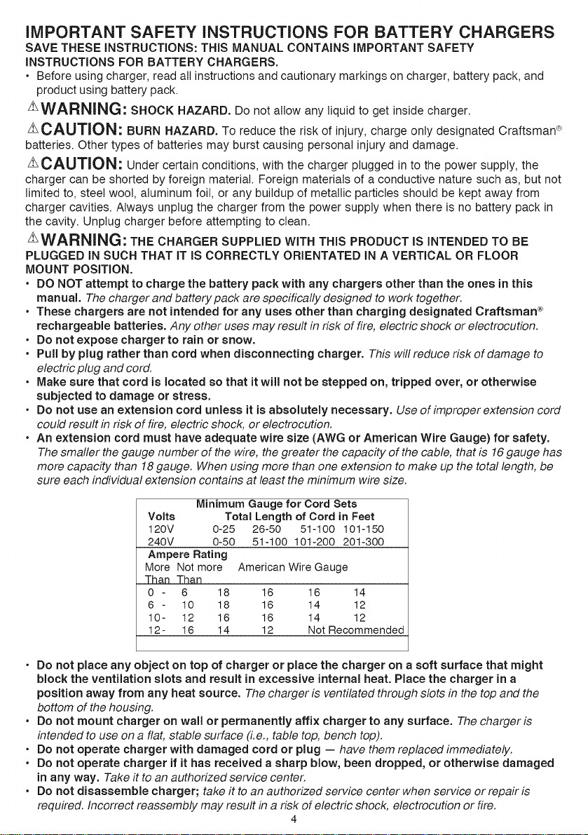
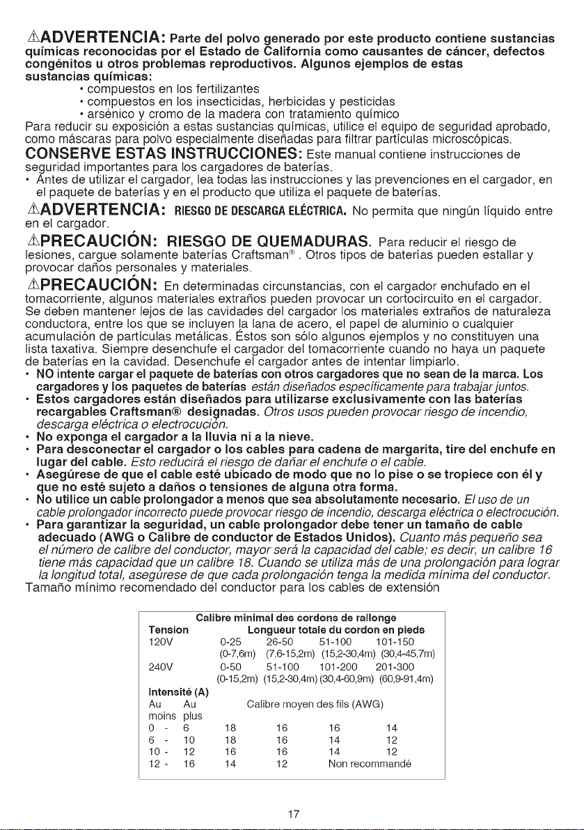
• An extension cord must have adequate wire size (AWG or American Wire Gauge) for safety.
The smaller the gauge number of the wire, the greater the capacity of the cable, that is 16gauge has
more capacity than 18gauge. When using more than one extension to make up the total length, be
sure each individual extension contains at least the minimum wire size.
Minimum Gauge for Cord Sets
Volts Total Length of Cord in Feet
120V 0-25 26-50 51-100 101-150
240V 0-50 51-100 101-200 201-300
Ampere Rating
More Not more American Wire Gauge
Than Than
0 - 6 18 16 16 14
6 - 10 18 16 14 12
10- 12 16 16 14 12
12- 16 14 12 Not Recommended
• Do not place any object on top of charger or place the charger on a soft surface that might
block the ventilation slots and result in excessive internal heat. Place the charger in a
position away from any heat source. The charger is ventilated through slots in the top and the
bottom of the housing.
• Do not mount charger on wall or permanently affix charger to any surface. The charger is
intended to use on a flat, stable surface (i.e., table top, bench top).
• Do not operate charger with damaged cord or plug -- have them replaced immediately.
• Do not operate charger if it has received a sharp blow, been dropped, or otherwise damaged
in any way. Take it to an authorized eervice center.
• Do not disassemble charger; take it to an authorized service center when service or repair is
required. Incorrect reassembly may result in a risk of electric shock, electrocution or fire.
4
• Disconnect the charger from the outlet before attempting any cleaning, This will reduce the risk
of electric shock. Removing the battery pack will not reduce this risk.
• NEVER attempt to connect 2 chargers together,
• The charger is designed to operate on standard household electrical power (120 Volts). Do
not attempt to use it on any other voltage.
iMPORTANT SAFETY iNSTRUCTiONS FOR BATTERY PACKS
WARNING: For safe operation, read this manual and manuals originally supplied with toot
before using the charger.
The battery pack is not fully charged out of the carton. Before using the battery pack and charger,
read the safety instructions below. Then follow charging procedures outlined.
READ ALL iNSTRUCTiONS
• Do not incinerate the battery pack even if it is severely damaged or is completely worn out.
The battery pack can explode in a fire. Toxic fumes and materials are created when battery packs
are burned.
• Do not charge or use battery in explosive atmospheres, such as in the presence of flammable
liquids, gases or dust. Inserting or removing the battery from the charger may ignite the dust or fumes.
• tf battery contents come into contact with the skin, immediately wash area with mild soap
and water, ff battery liquid gets into the eye, rinse water over the open eye for 15 minutes or
until irritation ceases. If medical attention is needed, the battery electrolyte for Li-ion batteries is
composed of a mixture of liquid organic carbonates and lithium salts.
• Contents of opened battery cells may cause respiratory irritation. Provide fresh air. If symptoms
persist, seek medical attention.
WARNING: BURN HAZARD. BA TTERY LIQUID MAY BE FLAMMABLE IF EXPOSED TO
SPARK OR FLAME.
• Charge the battery packs only in Craftsman _ chargers.
• DO NOT splash or immerse in water or other liquids. This may cause premature ceil failure.
• Do not store or use the tool and battery pack in locations where the temperature may reach
or exceed 105°F (40°C) (such as outside sheds or metal buildings in summer).
WARNING: Never attempt to open the battery pack for any reason. If battery pack case is
cracked or damaged, do not insert into charger. Do not crush, drop or damage battery pack. Do not
use a battery pack or charger that has received a sharp blow, been dropped, run over or damaged in
any way (i.e., pierced with a nail, hit with a hammer, stepped on). Damaged battery packs should be
returned to service center for recycling.
_WARNING: Fire hazard. Do not store or carry battery so that metal objects can contact
exposed battery terminals. For example, do not place battery in aprons, pockets, toot boxes,
product kit boxes, drawers, etc., with loose nails, screws, keys, etc. Transporting batteries can
possibly cause fires if the battery terminals inadvertently come in contact with conductive
materials such as keys, coins, hand tools and the like. The US Department of Transportation
Hazardous Material Regulations (HMR) actually prohibit transporting batteries in commerce or on
airplanes (i.e., packed in suitcases and carry-on luggage) UNLESS they are properly protected from
short circuits. So when transporting individual batteries, make sure that the battery terminals are
protected and weft insulated from materials that could contact them and cause a short circuit. NOTE:
M-ION batteries should not be put in checked baggage.
STORAGE RECOMMENDATIONS
1. The best storage place is one that is cool and dry away from direct sunlight and excess heat or cold.
2. Long-term storage will not harm the battery pack or charger, unless the battery is depleted.
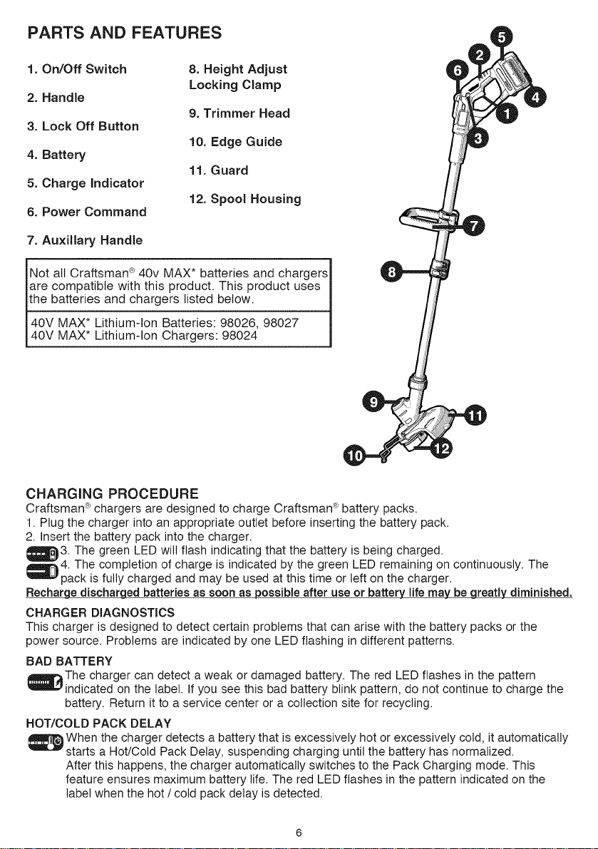
PARTS AND FEATURES
1. On/Off Switch
2. Handle
3. Lock Off Button
4. Battery
5. Charge indicator
6. Power Command
8. Height Adjust
Locking Clamp
9. Trimmer Head
10. Edge Guide
11. Guard
12. Spool Housing
7. Auxiliary Handle
Not all Craftsman c_40v MAX* batteries and chargers i
I
are compatible with this product. This product uses i
ithe batteries and chargers listed below. __
40V "'^"*MAXLithium-Ion Batteries: 98026, 98027 i
140V MAX* Lithium-Ion Chargers: 98024
CHARGING PROCEDURE
Craftsman _ chargers are designed to charge Craftsman _°'_battery packs.
1. Plug the charger into an appropriate outlet before inserting the battery pack.
2. Insert the battery pack into the charger.
_3. The green LED will flash indicating that the battery is being charged.
_,_4. The completion of charge is indicated by the green LED remaining on continuously. The
pack is fully charged and may be used at this time or left on the charger.
Recharge dischargedbatteries as soon as possibleafter use or battery life may be greatly diminished.
CHARGER DIAGNOSTICS
This charger is designed to detect certain problems that can arise with the battery packs or the
power source. Problems are indicated by one LED flashing in different patterns.
BAD BATTERY
_mw-_The charger can detect a weak or damaged battery. The red LED flashes in the pattern
indicated on the label. Ifyou see this bad battery blink pattern, do not continue to charge the
battery. Return it to a service center or a collection site for recycling.
HOT/COLD PACK DELAY
When the charger detects a battery that is excessively hot or excessively cold, it automatically
starts a Hot/Cold Pack Delay, suspending charging until the battery has normalized.
After this happens, the charger automatically switches to the Pack Charging mode. This
feature ensures maximum battery life. The red LED flashes in the pattern indicated on the
label when the hot / cold pack delay is detected.
LEAVINGTHEBATTERYINTHECHARGER
ThechargerandbatterypackcanbeleftconnectedwiththegreenLEDglowingindefinitely.The
chargerwillkeepthebatterypackfreshandfullycharged.
iMPORTANT CHARGING NOTES
1. Longest life and best performance can be obtained if the battery pack is charged when the air
temperature is between 60°F and 80°F (16°- 27°C). DO NOT charge the battery pack in an air
temperature below +40°F (+4.5°C), or above +t 05°F (+40.5°C). This is important and will prevent
serious damage to the battery pack.
2. The charger and battery pack may become warm to touch while charging. This is a normal
condition, and does not indicate a problem. To facilitate the cooling of the battery pack after use,
avoid placing the charger or battery pack in a warm environment such as in a metal shed, or an
uninsulated trailer.
3. If the battery pack does not charge properly:
a. Check current at receptacle by plugging in a lamp or other appliance
b. Check to see if receptacle is connected to a light switch which turns power off when you turn
out the lights.
c. Move charger and battery pack to a location where the surrounding air temperature is
approximately 60°F and 80°F (16°. 27°C).
d. If charging problems persist, take the tool, battery pack and charger to your local service center.
4. The battery pack should be recharged when it fails to produce sufficient power on jobs which were
easily done previously. DO NOT CONTINUE to use under these conditions. Follow the charging
procedure. You may also charge a partially used pack whenever you desire with no adverse affect
on the battery pack.
5. Foreign materials of a conductive nature such as, but not limited to, steel wool, aluminum foil,
or any buildup of metallic particles should be kept away from charger cavities. Always unplug the
charger from the power supply when there is no battery pack in the cavity. Unplug charger before
attempting to clean.
6. Do not freeze or immerse charger in water or any other liquid.
WARNING: SHOCK HAZARD. Do not allow any liquid to get inside charger. NEVER ATTEMPT
TO OPEN THE BATTERY PACK FOR ANY REASON, IF THE PLASTIC HOUSING OF THE BATTERY
PACK BREAKS OR CRACKS, RETURN TO A SERVICE CENTER FOR RECYCLING,
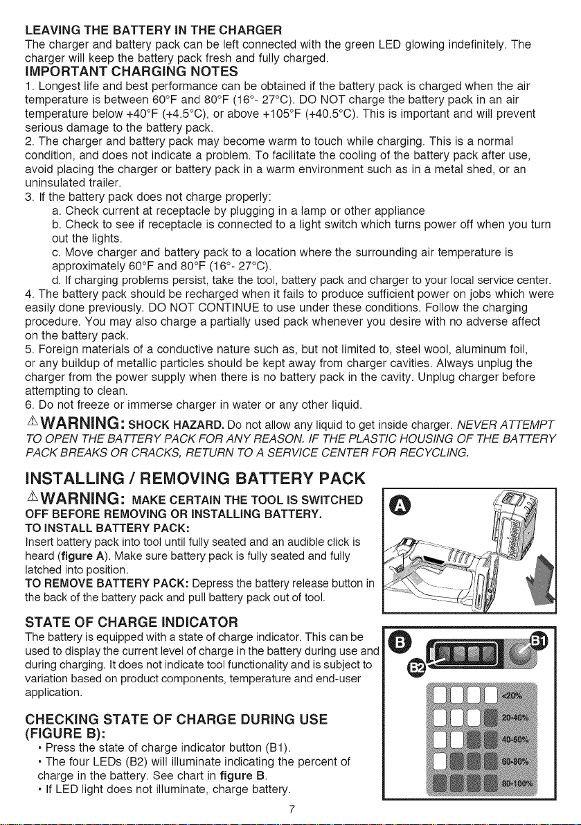
INSTALLING / REMOVING BATTERY PACK
AWARNING: MAKE CERTAIN THE TOOL tS SWITCHED
OFF BEFORE REMOVING OR INSTALLING BATTERY.
TO iNSTALL BATTERY PACK:
insertbattery pack into tool until fully seated and an audible click is
heard (figure A). Make sure battery pack is fully seated and fully
latched into position.
TO REMOVE BATTERY PACK: Depressthe battery release button in
the back of the battery pack and pull battery pack out of tool.
STATE OF CHARGE INDICATOR
The battery is equipped with a state of charge indicator. This can be
usedto display the current levelof charge in the battery during use and
during charging. It does not indicate tool functionality and issubject to
variation based on product components, temperature and end-user
application.
CHECKING STATE OF CHARGE DURING USE
(FIGURE B):
• Press the state of charge indicator button (Bt).
• The four LEDs (B2) will illuminate indicating the percent of
charge in the battery. See chart in figure B.
• If LED light does not illuminate, charge battery.
l
/_SwSEMBLY AND ADJUSTMENT
ARNING: BEFORE ASSEMBLY, MAKE SURE
THAT THE TOOL IS SWITCHED OFF AND THE BATTERY
HAS BEEN REMOVED.
ASSEMBLY TOOLS REQUIRED (NOT SUPPLIED):
- Phillips Screwdriver
LL_WAMNINL_: REMOVE THE BATTERY BEFORE
ATTEMPTING TO ATTACH ANY OF THE FOLLOWING
COMPONENTS.
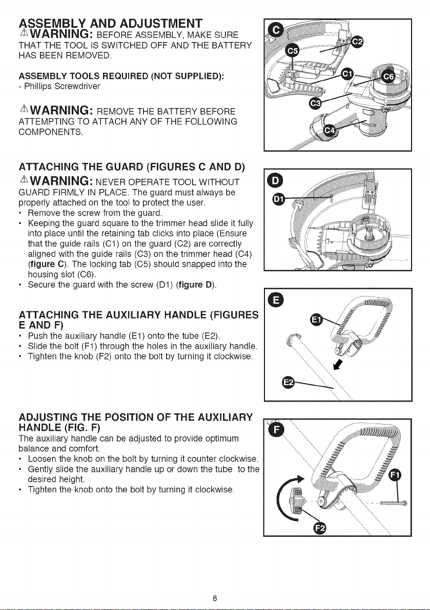
ATTACHING THE GUARD (FIGURES C AND D)
AWARNING: NEVER OPERATE TOOL WITHOUT
GUARD FIRMLY IN PLACE. The guard must always be
properly attached on the tool to protect the user.
• Remove the screw from the guard.
• Keeping the guard square to the trimmer head slide it fully
into place until the retaining tab clicks into place (Ensure
that the guide rails (C1) on the guard (C2) are correctly
aligned with the guide rails (C3) on the trimmer head (C4)
(figure C). The locking tab (C5) should snapped into the
housing slot (C6).
• Secure the guard with the screw (D1) (figure D).
ATTACHING THE AUXILIARY HANDLE (FIGURES
E AND F)
• Push the auxiliary handle (Et) onto the tube (E2).
• Slide the bolt (Ft) through the holes in the auxiliary handle.
• Tighten the knob (F2) onto the bolt by turning it clockwise.
ADJUSTING THE POSiTiON OF THE AUXiLiARY
HANDLE (FIG. F)
The auxiliary handle can be adjusted to provide optimum
balance and comfort.
• Loosen the knob on the bolt by turning it counter clockwise.
• Gently slide the auxiliary handle up or down the tube to the
desired height.
• Tighten the knob onto the bolt by turning it clockwise.
O
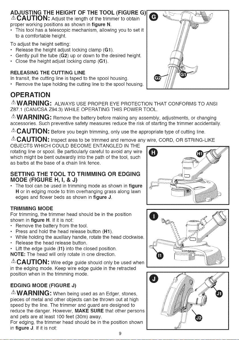
ADJUSTING THE HEIGHT OF THE TOOL (FIGURE G)
z_CAUTION: Adjust the length of the trimmer to obtain
proper working positions as shown in figure N.
• This tool has a telescopic mechanism, allowing you to set it
to a comfortable height.
To adjust the height setting:
• Release the height adjust locking clamp (G1).
• Gently pull the tube (G2) up or down to the desired height.
• Close the height adjust locking clamp (G1).
RELEASING THE CUTTING LINE
In transit, the cutting line is taped to the spool housing.
• Remove the tape holding the cutting line to the spool housing.
OPERATION
z_WARNING: ALWAYS USE PROPER EYE PROTECTION THAT CONFORMS TO ANSI
Z87.t (CAN/CSA Z94.3) WHILE OPERATING THIS POWER TOOL.
zLWARNING: Remove the battery before making any assembly, adjustments, or changing
accessories. Such preventive safety measures reduce the risk of starting the trimmer accidentally.
ACAUTION: Before you begin trimming, only use the appropriate type of cutting line.
z_CAUTION: Inspect area to be trimmed and remove an wire, CORD, OR STRING-LIKE
OBJECTS WHICH COULD BECOME ENTANGLED IN THE
rotating line or spool. Be particularly careful to avoid any wire
which might be bent outwardly into the path of the tool, such
as barbs at the base of a chain link fence.
SETTING THE TOOL TO TRIMMING OR EDGING
MODE (FIGURE H, I, & J)
• The tool can be used in trimming mode as shown in figure
H or in edging mode to trim overhanging grass along lawn
edges and flower beds as shown infigure J.
TRIMMING MODE
For trimming, the trimmer head should be in the position
shown in figure H. If it is not:
• Remove the battery from the tool.
• Press and hold the head release button (H1).
• While holding the auxiliary handle, rotate the head clockwise.
• Release the head release button.
• Lift the edge guide (11)into the closed position.
NOTE: The head will only rotate in one direction.
CAUTION: Wire edge guide should only be used when
in the edging mode. Keep wire edge guide in the retracted
position when in the trimming mode.
EDGING MODE (FIGURE J)
AWARNING: When being used as an Edger, stones,
pieces of metal and other objects can be thrown out at high
speed by the line. The trimmer and guard are designed to
reduce the danger. However, MAKE SURE that other persons
and pets are at least 100 feet (30m) away.
For edging, the trimmer head should be in the position shown
in figure J. If it is not:
9
o
o
o
o
o
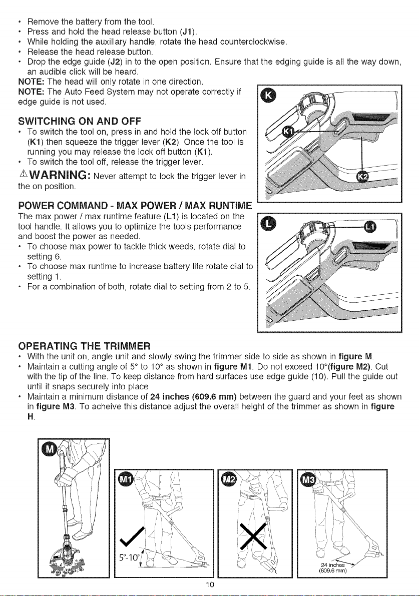
an audible click will be heard.
NOTE: The head will only rotate in one direction.
NOTE: The Auto Feed System may not operate correctly if
edge guide is not used.
Remove the battery from the tool.
Press and hold the head release button (J1).
While holding the auxiliary handle, rotate the head counterclockwise.
Release the head release button.
Drop the edge guide (J2) in to the open position. Ensure that the edging guide is all the way down,
SWITCHING ON AND OFF
• To switch the tool on, press in and hold the lock off button
(K1) then squeeze the trigger lever (K2). Once the tool is
running you may release the lock off button (K1).
• To switch the tool off, release the trigger lever.
AWARNING: Never attempt to lock the trigger lever in
the on position.
POWER COMMAND =MAX POWER / MAX RUNTIME
The max power / max runtime feature (L1) is located on the
tool handle. It allows you to optimize the tools performance
and boost the power as needed.
• To choose max power to tackle thick weeds, rotate dial to
setting 6.
• To choose max runtime to increase battery life rotate dial to
setting 1.
• For a combination of both, rotate dial to setting from 2 to 5.
OPERATING THE TRIMMER
• With the unit on, angle unit and slowly swing the trimmer side to side as shown in figure M.
• Maintain a cutting angle of 5° to 10° as shown in figure M1. Do not exceed 10°(figure M2). Cut
with the tip of the line. To keep distance from hard surfaces use edge guide (10). Pull the guide out
until it snaps securely into place
• Maintain a minimum distance of 24 inches (609.6 ram) between the guard and your feet as shown
in figure M3. To acheive this distance adjust the overall height of the trimmer as shown in figure
H.
/'_J _......
i/' \'\ '_/ {
lO
24 inche
(609.6 ram)
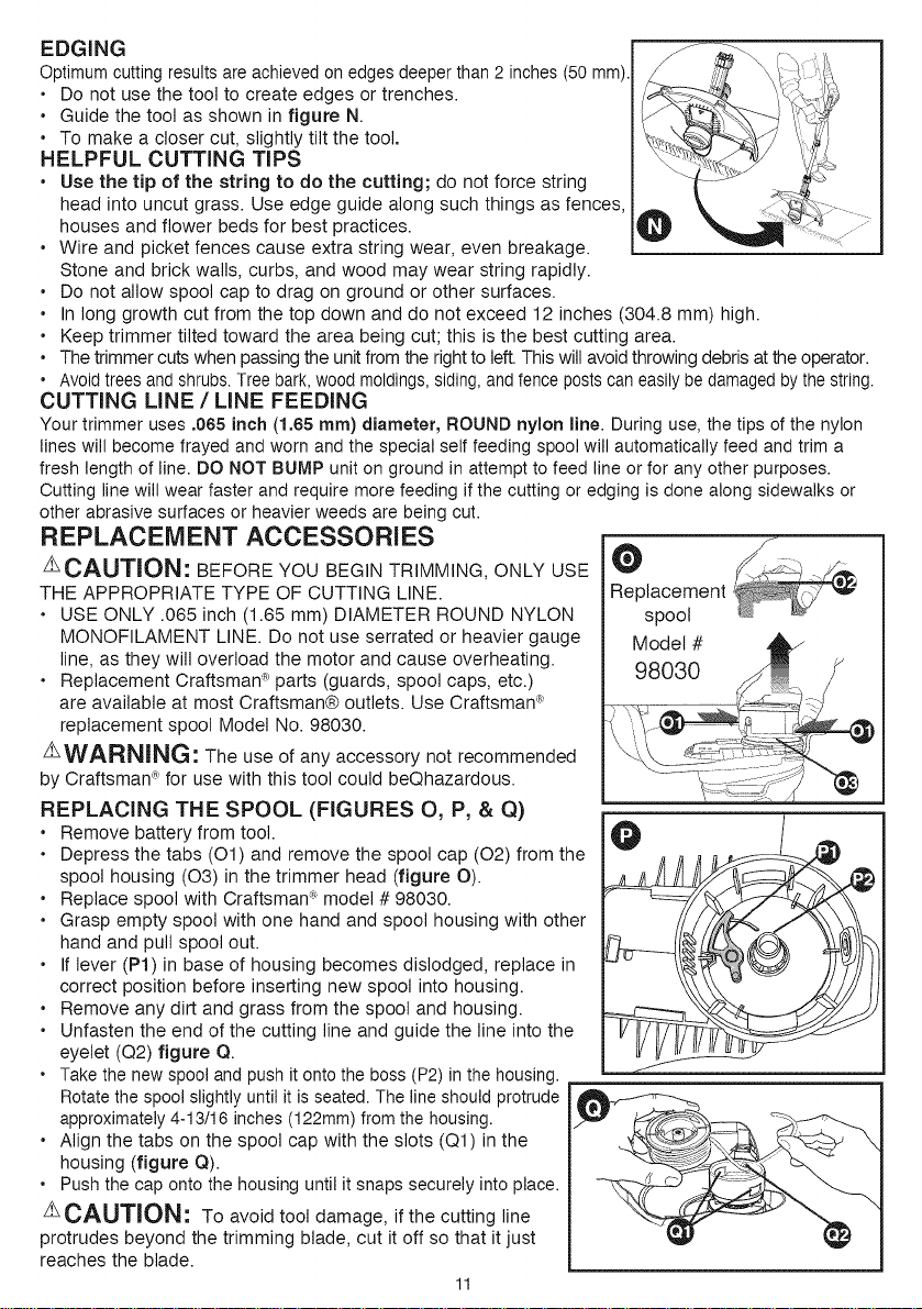
EDGING
Optimumcuttingresultsareachievedon edgesdeeperthan 2 inches(50ram).
• Do not use the tool to create edges or trenches.
• Guide the tool as shown in figure N.
• To make a closer cut, slightly tilt the tool.
HELPFUL CUTTING TIPS
• Use the tip of the string to do the cutting; do not force string
head into uncut grass. Use edge guide along such things as fences,
houses and flower beds for best practices.
• Wire and picket fences cause extra string wear, even breakage.
Stone and brick wails, curbs, and wood may wear string rapidly.
• Do not allow spool cap to drag on ground or other surfaces.
• In long growth cut from the top down and do not exceed 12 inches (304.8 ram) high.
• Keep trimmer tilted toward the area being cut; this is the best cutting area.
• Thetrimmer cuts when passingthe unit from therightto left.This will avoidthrowing debrisat the operator.
• Avoidtreesand shrubs.Treebark,wood moldings,siding,andfencepostscaneasilybe damagedbythe string.
CUTTING LINE / LINE FEEDING
Your trimmer uses .065 inch (1.65 ram) diameter, ROUND nylon line. During use, the tips of the nylon
lines will become frayed and worn andthe special self feeding spool will automatically feed and trim a
fresh length of line. DO NOT BUMP unit on ground in attempt to feed line or for any other purposes.
Cutting line will wear faster and require more feeding if the cutting or edging is done along sidewalks or
other abrasive surfaces or heavier weeds are being cut.
REPLACEMENT ACCESSORIES
ACAUTION: BEFORE YOU BEGIN TRIMMING, ONLY USE
THE APPROPRIATE TYPE OF CUTTING LINE.
• USE ONLY .085 inch (1.85 ram) DIAMETER ROUND NYLON
MONOFILAMENT LINE. Do not use serrated or heavier gauge
line, as they will overload the motor and cause overheating.
• Replacement Craftsman_R_parts (guards, spool caps, etc.)
are available at most Craftsman® outlets. Use Craftsman _'
replacement spool Model No. 98030.
z_WARNING: The use of any accessory not recommended
by Craftsman_"for use with this tool could beQhazardous.
REPLACING THE SPOOL (FIGURES O, P, & Q)
• Remove battery from tool.
• Depress the tabs (O1) and remove the spool cap (02) from the
spool housing (03) in the trimmer head (figure O).
• Replace spool with Craftsman_ model # 98030.
• Grasp empty spool with one hand and spool housing with other
hand and pull spool out.
• If lever (P1) in base of housing becomes dislodged, replace in
correct position before inserting new spool into housing.
• Remove any dirt and grass from the spool and housing.
• Unfasten the end of the cutting line and guide the line into the
eyelet (Q2) figure Q.
• Takethe newspool and push it ontothe boss (P2) in the housing.
Rotatethe spool slightly until it is seated.The line should protrude
approximately4-13/16 inches (122mm)fromthe housing.
• Align the tabs on the spool cap with the slots (Q1) in the
housing (figure Q).
• Pushthe cap onto the housing until it snaps securely into place.
Z_CAUTION : To avoid tool damage, if the cutting line
protrudes beyond the trimming blade, cut it off so that it just
reaches the blade.
11
/
O
Replacement
spool
Q
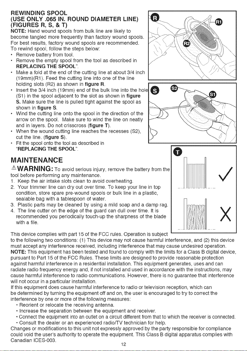
REWINDING SPOOL
(USE ONLY .065 IN. ROUND DIAMETER LINE)
(FIGURES R, S, & T)
NOTE: Hand wound spools from bulk line are likely to
become tangled more frequently than factory wound spools.
For best results, factory wound spools are recommended.
To rewind spool, follow the steps below:
• Remove battery from tool.
• Remove the empty spool from the tool as described in
REPLACING THE SPOOL".
• Make a fold at the end of the cutting line at about 3/4 inch
(19mm)(R1). Feed the cutting line into one of the line
holding slots (R2) as shown in figure R.
• Insert the 3/4 inch (19mm) end of the bulk line into the hole
($1) inthe spool adjacent to the slot as shown in figure
S. Make sure the line is pulled tight against the spool as
shown in figure S.
• Wind the cutting line onto the spool in the direction of the
arrow on the spool. Make sure to wind the line on neatly
and in layers. Do not crisscross (figure T).
• When the wound cutting line reaches the recesses ($2),
cut the line. (figure S).
• Fit the spool onto the tool as described in
"REPLACING THE SPOOL".
o
MAINTENANCE
AWARNING: To avoid serious injury, remove the battery from the
tool before performing any maintenance.
1. Keep the air intake slots clean to avoid overheating.
2. Your trimmer line can dry out over time. To keep your line in top
condition, store spare pre-wound spools or bulk line in a plastic,
sealable bag with a tablespoon of water.
3. Plastic parts may be cleaned by using a mild soap and a damp rag.
4. The line cutter on the edge of the guard can dull over time. It is
recommended you periodically touch-up the sharpness of the blade
with a file.
O
X
This device complies with part 15 of the FCC rules. Operation is subject
to the following two conditions: (1) This device may not cause harmful interference, and (2) this device
must accept any interference received, including interference that may cause undesired operation.
NOTE: This equipment has been tested and found to comply with the limits for a Class B digital device,
pursuant to Part 15 of the FCC Rules. These limits are designed to provide reasonable protection
against harmful interference in a residential installation. This equipment generates, uses and can
radiate radio frequency energy and, if not installed and used in accordance with the instructions, may
cause harmful interference to radio communications. However, there is no guarantee that interference
will not occur in a particular installation.
Ifthis equipment does cause harmful interference to radio or television reception, which can
be determined by turning the equipment off and on, the user is encouraged to try to correct the
interference by one or more ofthe following measures:
• Reorient or relocate the receiving antenna.
• Increase the separation between the equipment and receiver.
• Connect the equipment into an outlet on a circuit different from that to which the receiver is connected.
• Consult the dealer or an experienced radio/TV technician for help.
Changes or modifications to this unit not expressly approved by the party responsible for compliance
could void the user's authority to operate the equipment. This Class Bdigital apparatus complies with
Canadian ICES-003.
12
THE RBRC TM SEAL
The RBRCTM (Rechargeable Battery Recycling Corporation) Seal on the LI-ION battery
(or battery pack) indicates that the costs to recycle the battery (or battery pack) at the
end of its useful life have already been paid by Craftsman _.
RBRCTM in cooperation with Craftsman _ and other battery users, has established
programs in the United States to facilitate the collection of spent LI-ION batteries. Help
protect our environment and conserve natural resources by returning the spent LI-ION battery to an
authorized Craftsman _ service center or to your local retailer for recycling. You may also contact
your local recycling center for information on where to drop off the spent battery. RBRC TM is a
registered trademark of the Rechargeable Battery Recycling Corporation.
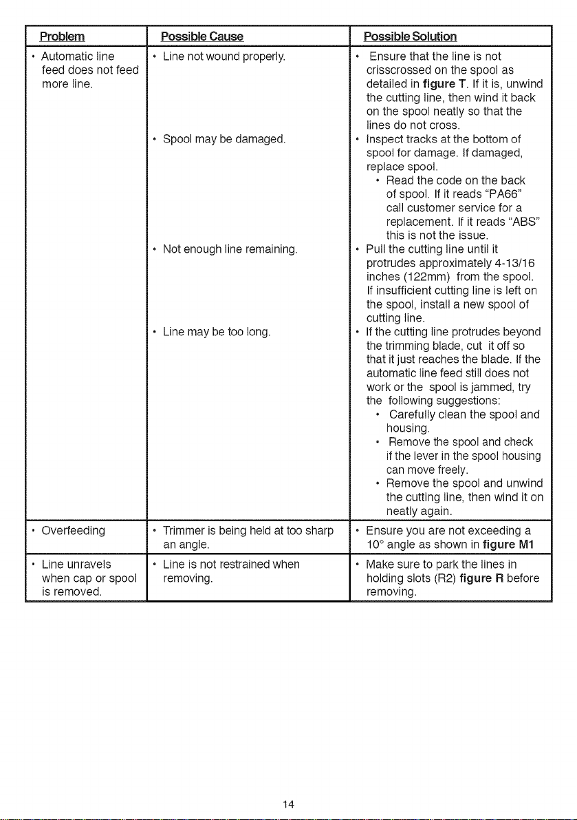
Problem
•Unit will not start.
• Battery won't
charge.
• Tool runs slowly.
TROUBLESHOOTING
Possible Cause
• Battery not installed properly.
• Battery not charged.
•Battery not inserted into charger.
• Charger not plugged in.
• Surrounding air temperature too
hot or too cold.
• Spool may have debris.
• Cutting line may be too long.
Possible Solution
Check battery installation.
Check battery charging
requirements.
• Insertbatteryintochargeruntilgreen
LEDappears.Charge up to 8 hours
if battery totally drained.
• Plug charger into a working
outlet. Refer to "Important
Charging Notes" for more
details.
• Check current at receptacle
by plugging in a lamp or other
appliance.
• Check to see if receptacle is
connected to a light switch which
turns power off when you turn out
the lights.
• Move charger and tool to a
surrounding air temperature of
above 40 degree F (4.5°C) or
below 105 degree F (40.5°C).
• Check that the spool housing can
rotate freely. Carefully clean it if
necessary.
• Check that the cutting line
does not protrude more than
approximately 4-13/16 inches
(122mm) from the spool If it does,
cut it off so that it just reaches the
line trimmingblade.
13
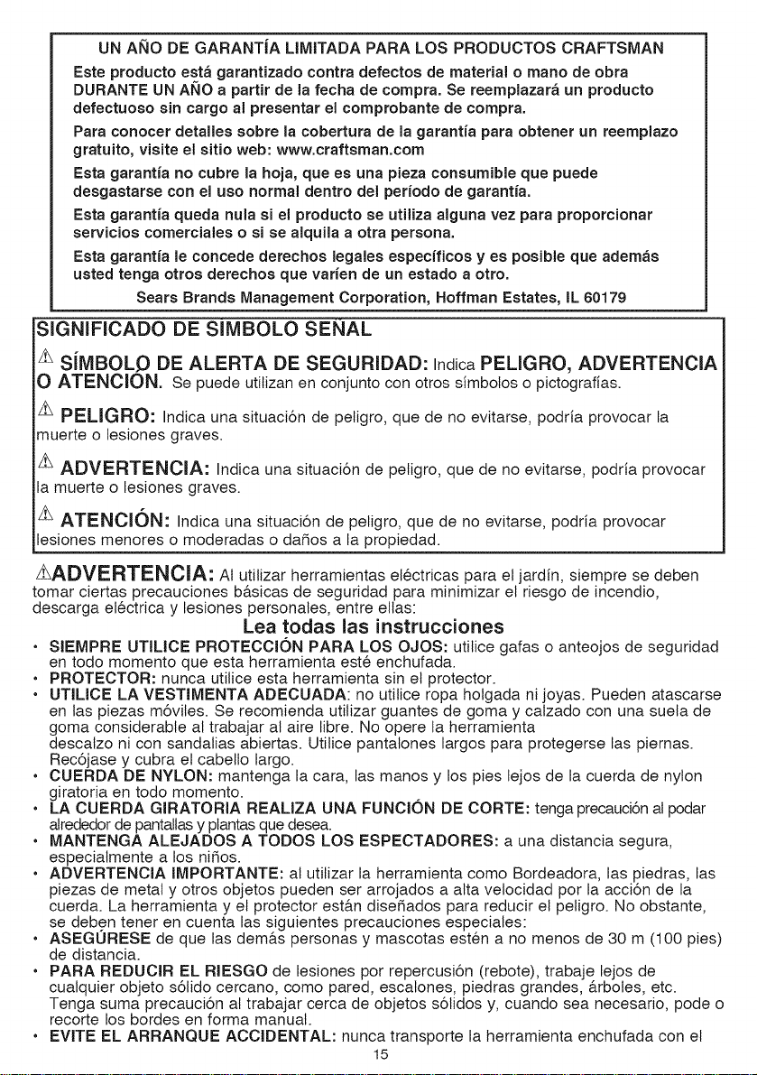
Problem
• Automatic line
feed does not feed
more line.
Possible Cause
Line not wound properly.
• Spool may be damaged.
Notenough line remaining.
• Line may be too long.
• Overfeeding • Trimmer is being held at too sharp
an angle.
• Line unravels • Line is not restrained when
when cap or spool removing.
is removed.
Possible Solution
Ensure that the line is not
crisscrossed on the spool as
detailed in figure T. Ifit is, unwind
the cutting line, then wind it back
on the spool neatly so that the
lines do not cross.
• Inspect tracks at the bottom of
spool for damage. If damaged,
replace spool.
• Read the code on the back
of spool. Ifit reads "PA66"
call customer service for a
replacement. Ifit reads "ABS"
this is notthe issue.
• Pull the cutting line until it
protrudes approximately 4-13/16
inches (122mm) from the spool.
Ifinsufficient cutting line is left on
the spool, install a new spool of
cutting line.
• Ifthe cutting line protrudes beyond
the trimming blade, cut it off so
that it just reaches the blade. Ifthe
automatic line feed still does not
work or the spool is jammed, try
the following suggestions:
• Carefully clean the spool and
housing.
• Remove the spool and check
if the lever in the spool housing
can move freely.
• Remove the spool and unwind
the cutting line, then wind it on
neatly again.
• Ensure you are not exceeding a
10° angle as shown in figure M1
• Make sure to park the lines in
holding slots (R2) figure R before
removing.
14
UN AkIO DE GARANTIA LIMITADA PARA LOS PRODUCTOS CRAFTSMAN
Este producto esta garantizado contra defectos de material o mano de obra
DUBANTE UN ANO a partir de la fecha de compra, Se reemplazara un producto
defectuoso sin cargo al presentar el comprobante de compra,
Para conocer detalles sobre la cobertura de la garantia para obtener un reemplazo
gratuito, visite el sitio web: www, craftsman,com
Esta garantia no cubre la hoja, que es una pieza consumible que puede
desgastarse con el uso normal dentro del periodo de garantia,
Esta garantia queda nula si el producto se utiliza alguna vez para proporcionar
servicios comerciales o si se alquila a otra persona,
Esta garantia le concede derechos Jegales especfficos y es posible que ademas
usted tenga otros derechos que varien de un estado a otto,
Sears Brands Management Corporation, Hoffman Estates, tL 60179
SIGNIFICADO DE SIMBOLO SENAL
'_ SiMBOLO DE ALERTA DE SEGURIDAD: IndicaPELIGRO, ADVERTENCIA
O ATENCION. Se puede utitizan en conjunto con otros simbotos o pictograflas.
zh PELIGRO: Indica una situaci6n de peligro, que de no evitarse, podria provocar la
muerte o lesiones graves.
zt ADVERTENCIA: Indica una situaci6n de peligro, que de no evitarse, podria provocar
la muerte o lesiones graves.
zt ATENCI()N: Indica una situaci6n de peligro, que de no evitarse, podria provocar
lesiones menores o moderadas o dafios a la propiedad.
z_ADVERTENCIA: At utilizar herramientas el6ctricas para el jardin, siempre se deben
tomar ciertas precauciones b&sicas de seguridad para minimizar el riesgo de incendio,
descarga el6ctrica y lesiones personales, entre elias:
Lea todas las instrucciones
• SIEMPRE UTILlCE PROTECCION PARA LOS OJOS: utilice galas o anteojos de seguridad
en todo momento que esta herramienta est6 enchufada.
• PROTECTOR: nunca utilice esta herramienta sin el protector.
• UTILICE LA VESTIMENTA ADECUADA: no utilice ropa holgada ni joyas. Pueden atascarse
en las piezas m6viles. Se recomienda utilizar guantes de goma y calzado con una suela de
goma considerable al trabajar al aire libre. No opere la herramienta
descatzo ni con sandalias abiertas. Utilice pantalones largos para protegerse las piernas.
Rec6jase y cubra el cabello largo.
• CUERDA DE NYLON: mantenga la cara, las manos y los pies lejos de la cuerda de nylon
giratoria en todo momento.
• LA CUERDA GIRATORIA REALIZA UNA FUNCION DE CORTE: tenga precauci6n al podar
alrededor de pantallas y plantas que desea.
• MANTENGA ALEJADOS A TODOS LOS ESPEOTADORES: a una distancia segura,
especiatmente a los nifios.
• ADVERTENCIA IMPORTANTE: al utilizar la herramienta como Bordeadora, las piedras, las
piezas de metal y otros objetos pueden ser arrojados a alta velocidad por la acci6n de la
cuerda. La herramienta y el protector est&n disefiados para reducir el peligro. No obstante,
se deben tener en cuenta las siguientes precauciones especiales:
• ASEGORESE de que las dem&s personas y mascotas est6n a no menos de 30 m (100 pies)
de distancia.
• PARA REDUClR EL RIESGO de lesiones por repercusi6n (rebote), trabaje lejos de
cualquier objeto s61ido cercano, como pared, escalones, piedras grandes, &rboles, etc.
Tenga suma precauci6n al trabajar cerca de objetos s61idos y, cuando sea necesario, pode o
recorte los bordes en forma manual.
• EVlTE EL ARRANQUE ACCIDENTAL: nunca transporte la herramienta enchufada con el
15
dedoenelinterrupter.
• NOFUERCELAHERRAMIENTA:aunavetocidadm&sr&pidadelavelocidadparalaquefue
diseSadaparacortaren forma eficaz.
• UTILICE LA HERRAMIENTA ADECUADA: no utitice esta herramienta para untrabajo diferente a
aqu6tlospara losque ruediseSada.
• NO SE ESTIRE: conserve el equitibrio adecuado y mant6ngase parade correctamente en
todo memento.
• DAKIO A LA UNIDAD: si gotpea la herramienta o _sta se atasca con un objeto extra5o,
det6ngala de inmediato, desenchOfela, verifique que no se haya da5ado y repare cualquier
da5o antes de seguir utitiz&ndola. No opere la herramienta si la bobina o el
carrete est&n da5ados.
• DESCONECTE LA HERRAMIENTA: cuando no la utitice, al reemplazar la cuerda o antes
de limpiarla.
• EVITE LAS CONDIClONES AMBIENTALES PELIGROSAS: no utilice herramientas
el6ctricas en lugares hOmedos o mojados. Siga todas las instrucciones incluidas en este
Manual de instrucciones para una operaci6n adecuada de la herramienta. No utitice la
herramienta bajo la Iluvia.
• NO OPERE herramientas el6ctricas port&tiles en atm6sferas gaseosas o exptosivas. Los
motores de estas herramientas normalmente chispean, y las chispas pueden encender los
vapores.
• GUARDE LAS HERRAMIENTAS QUE NO SE UTILlCEN EN EL INTERIOR: cuando no
las utilice, las herramientas deben guardarse en un lugar seco, alto o bajo llave, fuera det
alcance de los niSos. MANTi::NGASE ALERTA: No haga funcionar esta unidad si est& cans,ado,
enfermo o bajo la infiuencia del alcohol,drogas o medicamentos.
CONSERVE LAS HERRAMIENTAS ADECUADAMENTE: siga las instrucciones en la
secci6n de mantenimiento. Mantenga los mangos secos, limpios y libres de aceite y grasas.
• VERIFIQUE LAS PIEZAS AVERIADAS: antes de votver a utilizar la herramienta, se debe
controtar cuatquier protecci6n u otra pieza que est6 averiada para determinar si funcionar&
correctamente y realizar& la funci6n para la que rue dise5ada. Verifique la alineaci6n y la
sujeci6n de las piezas m6viles, la rotura de piezas, el montaje y cualquier otra condici6n que
pueda afectar el funcionamiento. Cuatquier protecci6n u otra pieza que est6 da5ada debe
ser reparada correctamente o reemplazada per un centre de mantenimiento autorizado, a
menos que este manual indique otra cosa.
• NO sumerja la herramienta en agua ni la salpique con una manguera. NO permita que
ningOn liquido entre en ella.
• NO guarde la herramienta sobre o cerca de fertilizantes o productos quimicos.
• NO timpie con una lavadora a presi6n.
Mantenga los protectores instatados adecuadamente yen funcionamiento.
• Mantenga las manes y los pies alejados del &rea de corte.
zhADVERTENCIA: No utitice la herramienta si el gatillo interrupter no enciende o apaga
la herramienta. Toda herramienta que no pueda controlarse mediante el gatilto interrupter es
petigrosa y debe repararse.
CONSERVE ESTAS INSTRUCClONES
S[MBOLOS
• La etiqueta de su herramienta puede incluir los siguientes simbolos. Los simbolos y
sus definiciones son los siguientes:
V.................. voltios
Hz................ hertz
min .............. minutes
- - - o DC.... corriente directa
_._................ Censtruccion Clase I
(mis a la terre)
[] Construccion de clase II _ ............. simbolo de alerta
.../min .......... revetucienes eminute seguridad
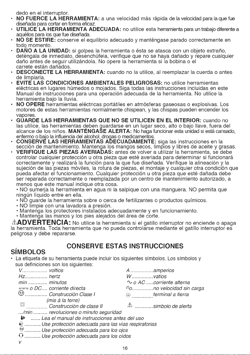
i_ ....... Lea el manual de instruccienes antes del use
............ Use preteccion adecuada para las vias respiraterias
G ............ Use preteccion adecuada para los ejes
0 ............ Use preteccion adecuada para los oidos
V
16
A ................ amperies
W ............... vaties
"_, e AC ..... cerriente alterna
no............... no velecidad sin carga
............... terminal a tierra
z_ADVERTENCIA: Parte del polvo generado pot este producto contiene sustancias
quimicas reconocidas pot el Estado de California como causantes de cancer, defectos
cong,6nitos u otros problemas reproductivos. AIgunos ejemplos de estas
sustancias quimicas:
• compuestos en los fertilizantes
• compuestos en los insecticidas, herbicidas y pesticidas
• ars6nico y cromo de la madera con tratamiento quimico
Para reducir su exposici6n a estas sustancias quimicas, utilice el equipo de seguridad aprobado,
como m&scaras para polvo especialmente disedadas para filtrar particulas microsc6picas.
CONSERVE ESTAS INSTRUCCIONES: Este manual contiene instrucciones de
seguridad importantes para los cargadores de baterias.
• Antes de utilizar el cargador, lea todas las instrucciones y las prevenciones en el cargador, en
el paquete de baterias yen el producto que utitiza el paquete de baterias.
z_ADVERTENOIA: RiESGODEDESCARGAELECTRiCA.No permita que ningQn liquido entre
en el cargador.
z_PRECAUCI(DN: RIESGO DE QUEMADURAS. Para reducir el riesgo de
lesiones, cargue solamente baterias Craftsman C_. Otros tipos de baterias pueden estallar y
provocar daSos personales y materiales.
z_PRECAUO_6N: En determinadas circunstancias, con el cargador enchufado en el
tomacorriente, algunos materiates extraSos pueden provocar un cortocircuito en el cargador.
Se deben mantener lejos de las cavidades del cargador los materiales extra5os de naturaleza
conductora, entre los que se incluyen !a lana de acero, el papel de aluminio o cuatquier
acumulaci6n de particulas met_.licas. Estos son s61o algunos ejemplos y no constituyen una
lista taxativa. Siempre desenchufe el cargador del tomacorriente cuando no haya un paquete
de baterias en la cavidad. Desenchufe el cargador antes de intentar limpiarlo.
• NO intente cargar el paquete de batedas con otros cargadores que no sean de la marc& Los
cargadores y Ice paquetes de batedas estgn disedados especificamente para trabajarjuntos.
• Estos cargadores estan diseSados para utilizarse e×clusivamente con las baterfas
recargables Craftsman@ designadas. Otros usos pueden provocar riesgo de incendio,
descarga el_ctrica o electrocuciSn.
• No e×ponga el cargador a la Iluvia ni a la nieve.
• Para desconectar el cargador o los cables para cadena de margarita, tire del enchufe en
lugar del cable. Esto reducir9 el riesgo de dadar el enchufe o el cable.
• Asegerese de que el cable este ubicado de modo que no Io pise o se tropiece con el y
que no este sujeto a daSos o tensiones de alguna otra forma.
• No utilice un cable prolongador a menos que sea absolutamente necesario. El uso de un
cable prolongador incorrecto puede provocar riesgo de incendio, descarga el6ctrica o electrocuciSn.
• Para garantizar la seguridad, un cable prolongador debe tenet un tamaSo de cable
adecuado (AWG o Calibre de conductor de Estados Unidos). Cuanto mbs pequedo sea
el nbmero de calibre del conductor, mayor serb la capacidad del cable; es decir, un calibre 16
tiene mgs capacidad que un calibre 18. Cuando se utiliza mgs de una prolongaciSn para Iograr
la Iongitud total, asegbrese de que cada prolongaciSn tenga la medida minima del conductor.
Tamado minimo recomendado del conductor para los cables de extensi6n
Calibre minimal des cordons de rallonge
Tension
120V
240V
Intensite (A)
Au Au
moins plus
0 - 6
6 - 10
10 - 12
12 - 16
Longueur totale du cordon en pieds
0-25 26-50 51-100 101-150
(0-7,6m) (7,6-15,2m) (15,2-30,4m) (30,4-45,7m)
0-50 51-100 101-200 201-300
(0-15,2m) (15,2-30,4m)(30,4-60,9m)(60,9-91,4m)
Calibre moyen des ills (AWG)
18 16 16 14
18 16 14 12
16 16 14 12
14 12 Nonrecommande
17
• No coloque objetos en la parte superior del cargador ni coloque el cargador en una
superficie blanda que pueda bloquear las ranuras de ventilaci6n y provocar un calor
interno e×cesivo. Coloque el cargador en una posici6n atejada de cualquier fuente de
calor. El cargador se ventila a trav6s de ranuras en la parte superior e inferior de la cubierta.
• No monte el cargador en la pared ni Io instale en forma permanente sobre ninguna
superficie. El cargador est& disedado para ser utitizado sobre una superficie plana y estable
(p. ej., un banco o una mesa).
• No opere et cargador con cables o enchufes dafiados: reemplgcelos de inmediato.
• No opere el cargador si este ha recibido un golpe fuerte, se ha ca[do, o se ha dafiado de
cualquier otra manera. Ll#velo a un centro de mantenimiento autorizado.
• No desarme el cargador; Ilevelo a un centro de mantenimiento autodzado cuando se
requiera mantenimiento o una reparaci6n. El armado incorrecto puede impficar un riesgo de
descarga el#ctrica, electrocuci6n o incendio.
• Antes de limpiaflo, desconecte el cargador del tomacorriente. Esto reducir& el riesgo de
descarga el6ctrica. Quitar el paquete de baterias no reducir& este riesgo.
• NUNCA intente conectar 2 cargadores juntos.
• El cargador esta disefiado para operar con corriente el6ctrica domestica estandar (120
voltios). No intente utilizarlo con otto voltaje.
zLADVERTENCIA: Para un funcionamiento seguro, lea _ste y todos los manuales de
instrucciones incluidos con la herramienta antes de usar el cargador.
El paquete de baterias incluido en la caja no est& completamente cargado. Antes de utilizar el
paquete de baterias y el cargador, lea las instrucciones de seguridad a continuaci6n. Luego, siga
los procedimientos de carga descritos.
LEA TODAS LAS INSTRUCClONES
• No incinere el paquete de bater_as, aun si tiene dafios importantes o esta completamente
desgastado. El paquete de baterias puede explotar en el fuego. Cuando se queman los
paquetes de baterias, se generan vapores y materiales tSxicos.
• No cargue ni use la bateria en atm6sferas explosivas, como ambientes en los que hay
liquidos, gases o polvo inflamables. Insertar o retirar la bateria del cargador puede encender
el polvo o los vapores.
• Si el contenido de las baterias entra en contacto con la piel, lave el area de inmediato
con agua y jab6n suave. Si el liquido de la bateria entra en contacto con los ojos, enjuague
con agua manteniendo los ojos abiertos durante 15 minutos o hasta que la irritaciSn cese. Si se
necesita atenciSn m_dica, el electrofito de/as baterias de iones de fitio contiene una mezcla de
carbonatos orgbnicos liquidos y sales de fitio.
• El contenido de las celulas de la bateria abierta puede causar irritaci6n respiratoria.
Respire aire fresco. Si los sintomas persisten, busque atenciSn m6dica.
zLADVERTENCIA: RIESGO DE QUEMADURAS. El liquido de la bateria puede encenderse si
se expone a chispas o llamas.
• Cargue los paquetes de baterias solamente en cargadores Craftsman@.
• NO satpique ni sumerja en agua u otros liquidos. Esto puede causar una falla prematura de
las c_lulas.
• No almacene ni utilice la herramienta y el paquete de bater_as en lugares en los que la
temperatura pueda alcanzar o superar los 40 °C (105 °F) (como en toldos al aire libre o
construcciones de metal en verano).
zLADVERTENClA: Nunca intente abrir et paquete de baterias por ningQn motivo. Si la
caja det paquete de baterias est& agrietada o dadada, no la introduzca en el cargador. No
comprima, deje caer ni da5e el paquete de baterias. No utitice un paquete de baterias o un
cargador que haya recibido un golpe fuerte, se haya caido, est6 agotado o dadado de alguna
forma (por ejemplo, perforado con un ctavo, golpeado con un martillo, pisado). Los paquetes de
baterias dafiados deben devotverse al centro de mantenimiento para su reciclado.
zLADVERTENClA: Riesgo de incendio. No guarde o transporte la bateria de ninguna
manera que permita que los terminales expuestos de la bateria entren en contacto con
objetos metalicos. Por ejempto, no coloque la bateria en delantales, bolsillos, cajas de
herramientas, cajas de juegos de productos, cajones, con clavos, tornillos, Ilaves sueltos, etc.
Transportar baterias puede provocar incendios si los terminales de la bateria entran en
contacto accidentalmente con materiales conductores como Haves, monedas,
18
herramientas manuales y similares. Las Normas para Materialea Peligrosos del
Departamento de Transporte de los EE.UU. (HMR) concretamente prohfben transportar
baterfas comercialmente o en aviones (es decir, empacadas en maletas y equipaje de
mano) A MENOS que eaten debidamente protegidas de cortocircuitos. Por Iotanto, cuando
transporte baterfas individuales, asegOrese de que los terminales de ta bateria est6n protegidos y
bien aistados de materiales que puedan hacer contacto y causar un cortocircuito. NOTA: Las
baterias de IONES DE LITIO no deben guardarse en el equipaje que se despacha.
RECOMENDACIONES CON RESPECTO AL ALMACENAMIENTO
1. El mejor lugar de almacenamiento es uno que sea fresco y seco fuera de la luz solar directa
y de un exceso de calor o frio.
2. El almacenamiento prolongado no dafiar& el paquete de baterfas o el cargador.
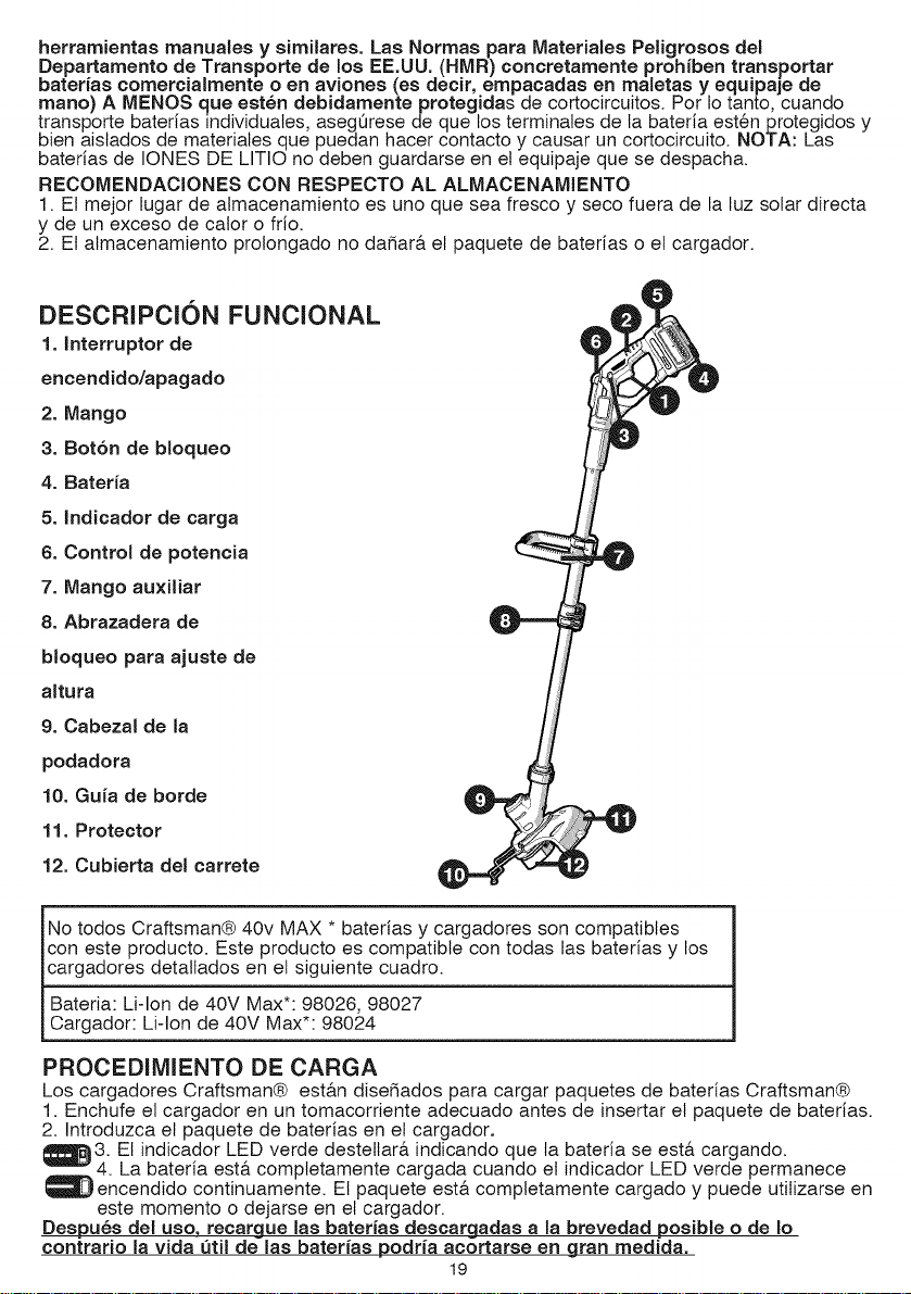
DESCRIPCION FUNCIONAL
1. Interruptor de
encendido/apagado
2. Mango
3. Bot6n de bloqueo
4. Baterfa
5. Indicador de carga
6. Control de potencia
7. Mango au×iliar
8. Abrazadera de
bloqueo para ajuste de
altura
9. Cabezal de la
podadora
10. Gufa de horde
11. Protector
12. Cubierta del carrete
No todos Craftsman® 40v MAX * baterias y cargadores son compatibles
con este producto. Este producto es compatible con todas las baterfas y los
cargadores detallados en el siguiente cuadro.
l Bateria: Li-lon de 40V Max*: 98026, 98027
Cargador: Li-lon de 40V Max*: 98024
PROCEDIMIENTO DE CARGA
Los cargadores Craftsman® est,_.ndise_ados para cargar paquetes de baterias Craftsman®
1. Enchufe el cargador en un tomacorriente adecuado antes de insertar el paquete de baterfas.
2. Introduzca el paquete de baterias en el cargador.
1_3 El indicador LED verde destellar& indicando que la bateria se est,. cargando.
. La baterfa est,. completamente cargada cuando el indicador LED verde permaneceq.
encendido continuamente. El paquete est& completamente cargado y puede utilizarse en
este momento o dejarse en el cargador.
Despues del uso, recargue las baterfas descargadas a la brevedad posible o de Io
contrario la vida _til de las baterfas podrfa acortarse en gran medida.
19
DIAGNOSTICO DEL CARGADOR
Este cargador est& disefiado para detectar ciertos probtemas que pueden surgir con los
paquetes de baterias o el cargador. Los problemas se indican mediante el indicador LED
&mbar, que destelta en diferentes patrones.
BATERJA DANAOA
_EI cargador puede detectar una bateria d6bit o dafiada. El indicador LED destellar& en el
patr6n indicado en la etiqueta. Si observa este patr6n de destello de bateria dafiada, no
continue cargando la bateria. Devu61vala a un centro de mantenimiento o a un lugar de
recolecci6n para reciclado.
RETRASO POR PAQUETE CALIENTE/FRJO
Cuando el cargador detecta que la bateria est& excesivamente caliente o fria, comienza
un Retraso por paquete caliente/frio, y suspende la carga hasta que la bateria se haya
normalizado. Despu6s que ocurra esto, el cargador cambia autom&ticamente al modo de
Paquete cargando. Esta funci6n garantiza la duraci6n m&xima de la bateria. El indicador
LED rojo destellar& en un patr6n indicado en la etiqueta cuando detecte el retraso por
paquete catiente / frio.
DEJAR EL PAQUETE DE BATERJAS EN EL CARGADOR
El cargador y el paquete de baterias se pueden dejar conectados con la luz verde encendida
indefinidamente. El cargador mantendr& el paquete de baterias como nuevo y completamente
cargado.
NOTAS IMPORTANTES SOBRE LA CARGA
1. Se puede obtener una mayor duraci6n y 6ptimo rendimiento si se carga el paquete de
baterias cuando latemperatura del aire est& entre los 16°C y los 27°C (60°F y 80°F). NO
cargue el paquete de bateria con una temperatura ambiental por debajo de +4,5 °C
(+40 °F) o por encima de +40,5 °C (+105 °F). Esto es importante y evitar& dafios graves en
el paquete de baterias.
2. El cargador y el paquete de baterias pueden estar catientes al tacto durante ta carga. Esto
es una condici6n normal y no indica un problema. Para facititar el enfriado del paquete
de baterias despu6s de su uso, evite colocar el cargador o el paquete de baterias en un
ambiente c&tido, como debajo de un toldo de metal o en un remolque sin aistamiento.
3. Si el paquete de baterias no se carga adecuadamente:
a. Revise el tomacorriente enchufando una I&mpara u otro aparato
b. Verifique si el tomacorriente est& conectado a un interruptor que corta la energia cuando
usted apaga la luz.
c. Mueva el cargador y el paquete de baterias a un lugar donde la temperatura ambiental sea
alrededor de 16 °C a 27 °C
(60 °F a 80 °F).
d. Si los probtemas de carga persisten, Ileve la herramienta, el paquete de baterias y el
cargador al centro de mantenimiento local.
4. Se debe recargar el paquete de baterias cuando no produce energia suficiente para tareas
que previamente realizaba con facilidad. NO CONTINUE utitizando la herramienta en estas
condiciones. Siga el procedimiento de carga. Tambi6n se puede cargar un paquete de
baterias parcialmente agotado cuando se desee, sin ningQn efecto negativo sobre 6stas.
5. Se deben mantener lejos de las cavidades det cargador los materiales extrafios de
naturaleza conductora, entre los que se incluyen la lana de acero, el papel de aluminio
o cualquier acumulaci6n de particulas met&licas. Siempre desenchufe el cargador del
tomacorriente cuando no haya un paquete de baterias en la cavidad. Desenchufe el
cargador antes de intentar limpiarlo.
6. No congele ni sumerja el cargador en agua ni en ningQn otto liquido.
&ADVERTENOIA: Riesgo de descarga electrica. No permita que ning0n liquido entre
en el cargador. Nunca intente abrir el paquete de baterias por ningbn motivo. Si la cubierta
protectora de pl4stico de! paquete de baterias se rompe o agrieta, devu41vala a un centro de
mantenimiento para su reciclado.
INSTALACION Y EXTRACCION DEL PAQUETE DE BATERIAS
&ADVERTENCIA: AsegOrese de que el bot6n de btoqueo est6 accionado para evitar el
accionamiento del interruptor antes de quitar o instalar la bateria.
2O
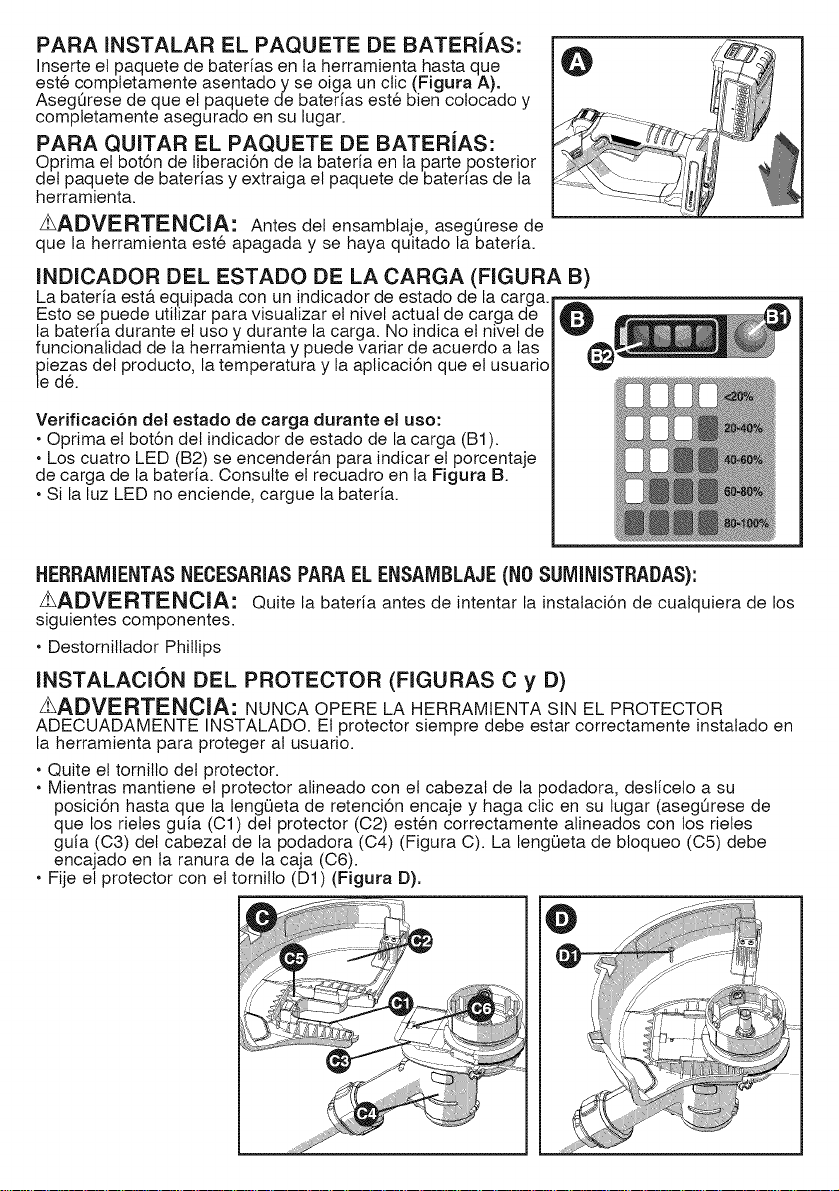
PARA INSTALAR EL PAQUETE DE BATERiAS:
Inserte el paquete de baterias en ta herramienta hasta que
est6 comptetamente asentado y se oiga un ctic (Figura A).
AsegQrese de que el paquete de baterias est6 bien cotocado y
completamente asegurado en su lugar.
PARA QUITAR EL PAQUETE DE BATERiAS:
Oprima el bot6n de liberaci6n de la bateria en la parte posterior
det paquete de baterias y extraiga el paquete de baterias de la
herramienta.
zLADVERTENCIA: Antes del ensambtaje, asegQrese de
que la herramienta est6 apagada y se haya quitado la bated&
INDICADOR DEL ESTADO DE LA CARGA (FIGURA B)
La bateria est& equipada con un indicador de estado de la carga.
Fsto se puede utilizar para visualizar el nivel actual de carga de
la bateria durante el uso y durante la carga. No indica el nivel de
funcionalidad de la herramienta y puede variar de acuerdo alas
_eieZasdel producto, la temperatura y la aplicaci6n que el usuario
d&
Verificaci6n del estado de carga durante el uso:
• Optima et bot6n del indicador de estado de la carga (B1).
• Los cuatro LED (B2) se encender&n para indicar el porcentaje
de carga de la bateria. Consutte el recuadro en la Figura B.
• Si la luz LED no enciende, cargue la bateria.
HERRAIVllENTASNECESARIASPARAEL ENSAlViBLAJE(NOSUIViINISTRADAS):
_ADVERTENCIA: Quite la bateria antes de intentar la instalaci6n de cualquiera de los
siguientes componentes.
• Destomillador Phillips
INSTALACiON DEL PROTECTOR (FIGURAS C y D)
zLADVERTENClA: NUNCA OPFRF LA HFRRAMIFNTA SIN EL PROTECTOR
ADECUADAMENTF INSTALADO. Fi protector siempre debe estar correctamente instalado en
la herramienta para proteger al usuario.
• Quite el tomitlo det protector.
• Mientras mantiene el protector alineado con el cabezal de la podadora, desticeto a su
posici6n hasta que la lengQeta de retenci6n encaje y haga clic en su lugar (asegQrese de
que los rieles guia (C1) del protector (C2) est6n correctamente alineados con los rieles
guia (C3) det cabezal de la podadora (C4) (Figura C). La lengQeta de bloqueo (C5) debe
encajado en ta ranura de la caja (C6).
• Fije el protector con el tornillo (D1) (Figura D).
O
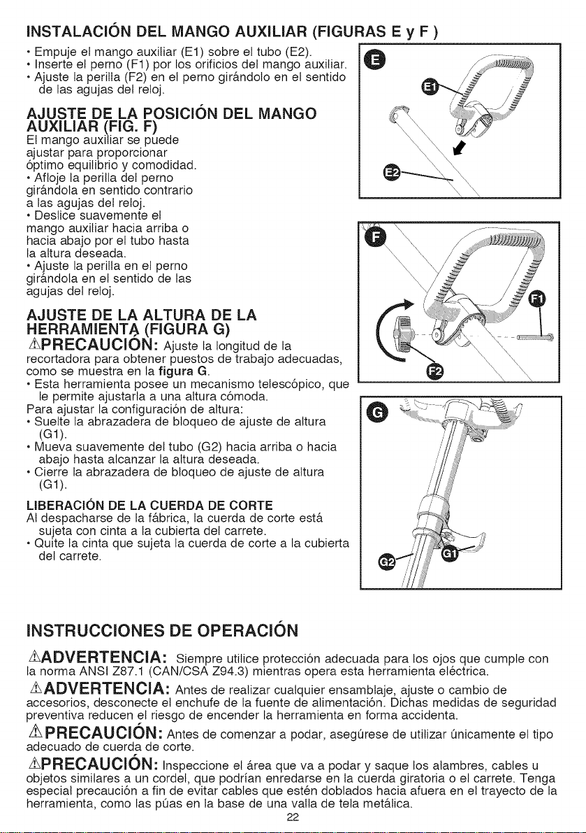
INSTALACION DEL MANGO AUXILIAR (FIGURAS E y F )
• Empuje el mango auxiliar (El) sobre el tubo (E2).
• Inserte el perno (F1) por los orificios del mango auxiliar.
• Ajuste la perilta (F2) en el pemo gir&ndoto en el sentido
de las agujas del reloj.
AJUSTE DE LA POSICION DEL MANGO
AUXILIAR (FIG. F)
El mango auxitiar se puede
ajustar para proporcionar
6ptimo equilibrio y comodidad.
• Afloje la perilla del perno
gir&ndola en sentido contrario
a las agujas del reloj.
• Destice suavemente el
mango auxitiar hacia arriba o
hacia abajo pot el tubo hasta
la altura deseada.
• Ajuste la perilla en el perno
gir&ndola en el sentido de las
agujas del reloj.
AJUSTE DE LA ALTURA DE LA
HERRAMIENT.€ (FIGURA G)
zLPRECAUCION: Ajuste la Iongitud de la
recortadora para obtener puestos de trabajo adecuadas,
como se muestra en la figura G.
• Esta herramienta posee un mecanismo tetesc6pico, que
le permite ajustarla a una altura c6moda.
Para ajustar la configuraci6n de altura:
• Suelte la abrazadera de btoqueo de ajuste de altura
(G1).
• Mueva suavemente del tubo (G2) hacia arriba o hacia
abajo hasta alcanzar la altura deseada.
• Cierre la abrazadera de bloqueo de ajuste de altura
(G1).
LIBERACION DE LA CUERDA DE CORTE
AI despacharse de la f&brica, la cuerda de corte est&
sujeta con cinta a la cubierta del carrete.
• Quite la cinta que sujeta la cuerda de corte a la cubierta
del carrete.
\ \
INSTRUCCIONES DE OPERACION
zLADVERTENClA: Siempre utilice protecci6n adecuada para los ojos que cumple con
la norma ANSI Z87.1 (CAN/CSA Z94.3) mientras opera esta herramienta el6ctrica.
z_ADVERTENOIA: Antes de realizar cualquier ensambtaje, ajuste o cambio de
accesorios, desconecte el enchufe de la fuente de alimentaci6n. Dichas medidas de seguridad
preventiva reducen el riesgo de encender la herramienta en forma accidenta.
ZLPRECAUCION: Antes de comenzar a podar, asegQrese de utitizar Qnicamente el tipo
adecuado de cuerda de corte.
zLPRECAUCION: Inspeccione el &rea que va a podar y saque los alambres, cables u
objetos similares a un cordel, que podrfan enredarse en la cuerda giratoria o el carrete. Tenga
especial precauci6n a fin de evitar cables que est6n doblados hacia afuera en el trayecto de la
herramienta, como las pQas en la base de una vaNa de tela met&lica.
22
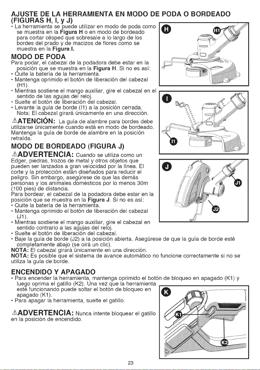
AJUSTE DE LA HERRAMIENTA EN MODO DE PODA O BORDEADO
(FIGURAS H, i, y J)
• La herramienta se puede utilizar en modo de poda como
se muestra en ta Figura H o en modo de bordeado
para cortar c6sped que sobresale a Io largo de los
bordes del prado y de macizos de flores como se
muestra en la Figura I.
iVlODO DE PODA
Para podar, el cabezal de la podadora debe estar en la
posici6n que se muestra en la Figura H. Si no es asi:
• Quite la bateria de la herramienta.
• Mantenga oprimido el bot6n de liberaci6n del cabezal
(H1).
• Mientras sostiene el mango auxiliar, gire el cabezal en el
sentido de las agujas del reloj.
• Suelte el bot6n de liberaci6n del cabezal.
• Levante la guia de borde (11) a la posici6n cerrada.
Nota: El cabezal girar& Qnicamente en una direcciSn.
%ATENCK)N: La guia de alambre para bordes debe
utilizarse Qnicamente cuando est& en modo de bordeado.
Mantenga la guia de borde de alambre en la posiciSn
retraida.
MODO DE BORDEADO (FIGURA J)
%ADVERTENOIA: Cuando se utiliza como un
Edger, piedras, trozos de metal y otros objetos que
pueden ser lanzados a gran velocidad por la line& El
corte y la protecciSn est&n dise5ados para reducir el
peligro. Sin embargo, asegQrese de que las dem&s
personas y los animales dom6sticos por Io menos 30m
(100 pies) de distancia.
Para bordear, el cabezal de la podadora debe estar en la
posici6n que se muestra en la Figura J. Si no es asi:
• Quite la bateria de la herramienta.
• Mantenga oprimido el bot6n de liberaci6n del cabezal
(J1).
• Mientras sostiene el mango auxiliar, gire el cabezal en
sentido contrario a las agujas del reloj.
• Suette el bot6n de liberaci6n del cabezat.
• Baje la guia de borde (J2) a ta posici6n abierta. AsegQrese de que la guia de borde est6
comptetamente abajo (se oir& un clic).
NOTA: Et cabezal girar& Qnicamente en una direcci6n.
NOTA: Es posible que el sistema de avance autom&tico no funcione correctamente si no se
utitiza la guia de borde.
ENCENDIDO Y APAGADO
• Para encender la herramienta, mantenga oprimido el bot6n de bloqueo en apagado (K1) y
luego oprima el gatiflo (K2). Una vez que la herramienta
est6 funcionando puede soltar el bot6n de bloqueo en
apagado (K1).
• Para apagar la herramienta, suelte el gatitlo.
zLADVERTENClA: Nunca intente bloquear el gatitlo
en la posiciSn de encendido.
23
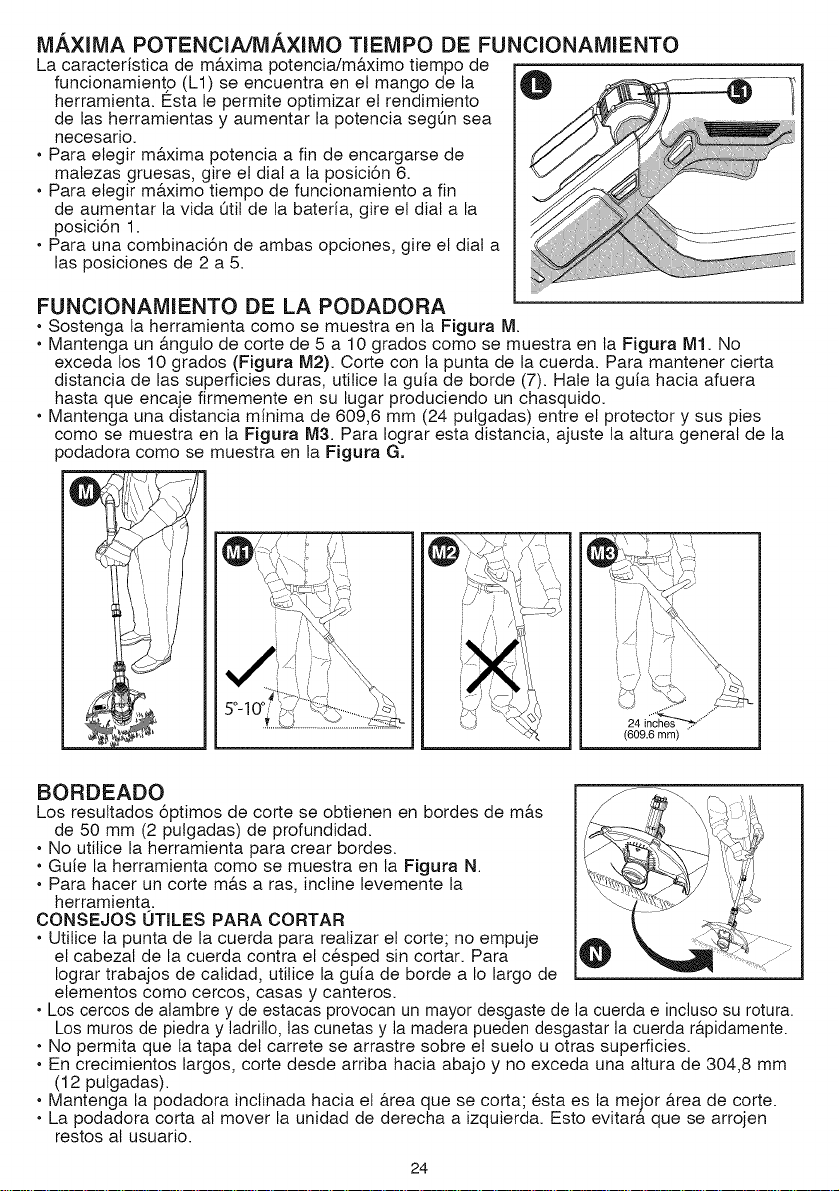
MAXIMA POTENCIA/MAXIMO TIEMPO DE FUNCIONAMIENTO
La caracter{stica de ma.xima potencia/ma.ximo tiempo de
funcionamiento (L1) se encuentra en el mango de la
herramienta. I_sta le permite optimizar el rendimiento
de las herramientas y aumentar la potencia segQn sea
necesario.
• Para elegir m&xima potencia a fin de encargarse de
malezas gruesas, gire el dial a la posici6n 6.
• Para elegir m&ximo tiempo de funcionamiento a fin
de aumentar la vida Otit de la bateria, gire el dial a la
posici6n 1.
• Para una combinaci6n de ambas opciones, gire el dial a
las posiciones de 2 a 5.
FUNCIONAMIENTO DE LA PODADORA
• Sostenga la herramienta como se muestra en la Figura M.
• Mantenga un &nguto de corte de 5 a 10 grados como se muestra en la Figura M1. No
exceda los 10 grados (Figura M2). Corte con la punta de la cuerda. Para mantener cierta
distancia de las superficies duras, utilice la guia de borde (7). Hale la guia hacia afuera
hasta que encaje firmemente en su lugar produciendo un chasquido.
• Mantenga una distancia minima de 609,6 mm (24 pulgadas) entre el protector y sus pies
como se muestra en la Figura M3. Para Iograr esta distancia, ajuste la altura general de la
podadora como se muestra en la Figura G.
BORDEADO
Los resultados 6ptimos de corte se obtienen en bordes de m&s
de 50 mm (2 pulgadas) de profundidad.
• No utilice la herramienta para crear bordes.
• Guie la herramienta como se muestra en la Figura N.
• Para hacer un corte m&s a ras, incline levemente la
herramienta.
CONSEJOS 0TILES PARA CORTAR
• Utilice la punta de la cuerda para realizar el corte; no empuje
el cabezal de la cuerda contra el c6sped sin cortar. Para
Iograr trabajos de calidad, utilice la guia de borde a Io largo de
elementos como cercos, casas y canteros.
• Los cercos de alambre y de estacas provocan un mayor desgaste de la cuerda e incluso su rotura.
Los muros de piedra y ladrillo, las cunetas y la madera pueden desgastar la cuerda r&pidamente.
• No permita que la tapa del carrete se arrastre sobre el sueto u otras superficies.
• En crecimientos largos, corte desde arriba hacia abajo y no exceda una altura de 304,8 mm
(12 pulgadas).
• Mantenga la podadora inctinada hacia el &rea que se corta; 6sta es la mejor &rea de corte.
• La podadora corta al mover la unidad de derecha a izquierda. Esto evitar& que se arrojen
restos al usuario.
24
• Evite &.rboles y arbustos. La cuerda fAcilmente puede dafiar la corteza de &.rboles, las
molduras de madera, los revestimientos exteriores y los pilares de cercos.
CUERDA DE CORTFJALIMENTACION DE LA CUERDA
Su podadora utiliza una cuerda de nation REDONDA de 1,7 mm (0,065 pulgada) de di&.metro.
Durante el uso, las puntas de las cuerdas de naiton se deshilacharAn y desgastar&.n, y et
carrete especial de autoalimentaci6n alimentarA y recortar&, autom&.ticamente un nuevo trozo
de cuerda. No gotpee ta unidad contra el suelo para intentar alimentar la cuerda ni por algQn
otro motivo. La cuerda de corte se desgastarA m&.srApido y necesitarA mAs alimentaci6n si
el corte o el bordeado se realizan a Io largo de aceras u otras superficies abrasivas, o si se
cortan malezas mAs espesas.
ACCESORIOS DE REPUESTO
Z_ATENCION: Antes de comenzar a podar, asegQrese de utitizar Qnicamente el tipo
apropiado de cuerda de corte.
Utilice el carrete de repuesto de Craftsman® modelo N.° 98030.
Recargue la cuerda de nation (a granel o en carrete de repuesto pre-enrollado) como se
muestra .en este manual.
• UTILICE UNICAMENTE CUERDA DE MONOFILAMENTO REDONDO DE NAILON DE 1,7
mm (0,065 pulgada) DE DIAMETRO. No utitice cuerdas dentadas o de mayor calibre ya que
sobrecargar&n el motor y provocar&n sobrecalentamiento. Puede conseguir esta cuerda a
trav6s de su distribuidor local o centro de mantenimiento autorizado.
• Las piezas de recambio Craftsman® (guardias, carrete casquillos, etc.) est&n disponibles en
m&s puntos de Craftsman®. Carrete de repuesto de uso Craftsman® Modelo N° 98030.
zhADVERTENClA: Elusode accesorios no
recomendados por Craftsman® para esta herramienta puede
ser peligroso.
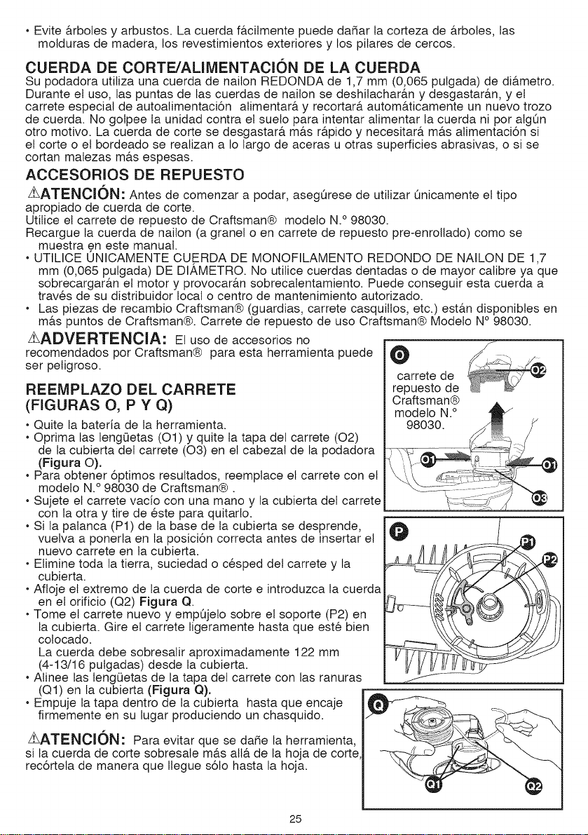
REEMPLAZO DEL CARRETE
(FIGURAS O, P Y Q)
• Quite la bateria de la herramienta.
• Oprima las lengQetas (O1) y quite la tapa del carrete (02)
de la cubierta del carrete (03) en el cabezal de la podadora
(Figura O).
• Para obtener 6ptimos resuttados, reemplace el carrete con el
modelo N.° 98030 de Craftsman®.
Sujete el carrete vacio con una mano y la cubierta del carrete
con la otra y tire de 6ste para quitarlo.
• Si la palanca (P1) de la base de ta cubierta se desprende,
vuelva a ponerla en la posici6n correcta antes de insertar el
nuevo carrete en la cubierta.
• Elimine toda la tierra, suciedad o c_sped del carrete y la
cubierta.
• Afioje el extremo de la cuerda de corte e introduzca la cuerda
en el orificio (Q2) Figura Q.
• Tome el carrete nuevo y empQjelo sobre el soporte (P2) en
la cubierta. Gire el carrete ligeramente hasta que est6 bien
colocado.
La cuerda debe sobresalir aproximadamente 122 mm
(4-13/16 putgadas) desde la cubierta.
• Atinee las lengQetas de la tapa del carrete con las ranuras
(Q1) en la cubierta (Figura Q).
• Empuje la tapa dentro de la cubierta hasta que encaje
firmemente en su lugar produciendo un chasquido.
ZLATENClON: Para evitar que se dafie la herramienta,
si la cuerda de corte sobresale m&s all&.de la hoja de corte
rec6rtela de manera que Ilegue s61o hasta la hoja.
O J
carrete de
repuesto de
25
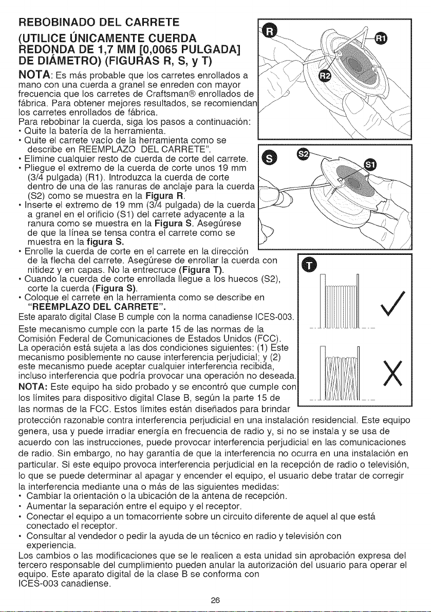
REBOBINADO DEL CARRETE
(UTILICE 0NICAMENTE CUERDA
REDONDA DE 1,7 MM [0,0065 PULGADA]
DE DIAMETRO) (FIGURAS R, S, y T)
NOTA: Es m&s probable que los carretes enroltados a
mano con una cuerda a granel se enreden con mayor
frecuencia que los carretes de Craftsman® enrollados de
f&brica. Para obtener mejores resuttados, se recomiendan
los carretes enrollados de f&brica.
Para rebobinar la cuerda, siga los pasos a continuaci6n:
• Quite la bateria de la herramienta.
• Quite el carrete vacio de la herramienta como se
describe en REEMPLAZO DEL CARRETE".
• Elimine cualquier resto de cuerda de corte del carrete.
• Pliegue el extremo de la cuerda de corte unos 19 mm
(3/4 putgada) (R1). Introduzca la cuerda de corte
dentro de una de las ranuras de anctaje para la cuerda
($2) como se muestra en la Figura R
• Inserte el extremo de 19 mm (3/4 pulgada) de la cuerda
a granel en el orificio ($1) del carrete adyacente a la
ranura como se muestra en la Figura S. AsegOrese
de que la linea se tensa contra el carrete como se
muestra en la figura S.
• Enrolte la cuerda de corte en el carrete en la direcci6n
de la flecha del carrete. AsegQrese de enrollar la cuerda con
nitidez y en capas. No la entrecruce (Figura T).
• Cuando la cuerda de corte enroltada Ilegue a los huecos ($2),
corte la cuerda (Figura S).
• Cotoque el carrete en la herramienta como se describe en
"REEMPLAZO DEL CARRETE".
Este aparato digital Clase B cumple con la norma canadiense ICES-003.
Este mecanismo cumple con la parte 15 de las normas de la
Comisi6n Federal de Comunicaciones de Estados Unidos (FCC).
La operaci6n est& sujeta alas dos condiciones siguientes: (1) Este
mecanismo posiblemente no cause interferencia perjudicial; y (2)
este mecanismo puede aceptar cualquier interferencia recibida,
incluso interferencia que podria provocar una operaci6n no deseada.
NOTA: Este equipo ha sido probado y se encontr6 que cumpte con
los limites para dispositivo digital Clase B, segQn ta parte 15 de
las normas de la FCC. Estos limites est&n dise5ados para brindar
@
protecci6n razonabte contra interferencia perjudicial en una instataci6n residencial. Este equipo
genera, usa y puede irradiar energia en frecuencia de radio y, si no se instata y se usa de
acuerdo con las instrucciones, puede provocar interferencia perjudicial en las comunicaciones
de radio. Sin embargo, no hay garantia de que la interferencia no ocurra en una instalaci6n en
particular. Si este equipo provoca interferencia perjudicial en la recepci6n de radio o televisi6n,
Io que se puede determinar al apagar y encender el equipo, el usuario debe tratar de corregir
la interferencia mediante una o m&s de las siguientes medidas:
• Cambiar la orientaci6n o la ubicaci6n de la antena de recepci6n.
• Aumentar la separaci6n entre el equipo y el receptor.
• Conectar el equipo a un tomacorriente sobre un circuito diferente de aquel al que est&
conectado el receptor.
• Consultar al vendedor o pedir la ayuda de un t6cnico en radio y televisi6n con
experiencia.
Los cambios o las modificaciones que se le realicen a esta unidad sin aprobaci6n expresa del
tercero responsable del cumptimiento pueden anular la autorizaci6n del usuario para operar el
equipo. Este aparato digital de la clase B se conforma con
ICES-003 canadiense.
26
EL SELLO RBRC TM
El selto RBRO TM (Corporaci6n de recictado de baterias recargables) que se
encuentra en la bateria de iones de litio (o paquete de baterias) indica que los
costos de recictar la bateria (o el paquete de baterias) al final de su vida Qtitya
fueron pagados por Craftsman®.
RBRC TM en cooperaci6n con Craftsman® y otros usuarios de baterias, ha
establecido programas en los Estados Unidos para facilitar la recolecci6n de baterias de
iones de litio agotadas. Ayude a proteger nuestro medio ambiente y a conservar los recursos
naturales: devuelva las baterias de iones de litio agotadas a un centro de mantenimiento
autorizado de Craftsman® o a un comerciante minorista local para que se recicten. TambiOn
puede comunicarse con el centro local de reciclado para obtener informaci6n sobre dOnde
dejar las batedas agotadas. RBRO TM es una marca comercial registrada de la Corporaci6n de
reciclado de baterias recargables.
Problema
•La unidad no
enciende.
•Labaterianose
carga.
•Laherramienta
funcionalentamente.
Causa uosible
• La bateria no se ha instalado
correctamente.
• La bateria no se cargar&.
DETECClON DE PROBLEMAS
Soluci6n _osible
• Compruebe la instalaci6n de la
bateria.
• Verifique los requisitos de carga
de baterias.
• Labaterianose insertaenel cargador.
• Elcargadornoenchufado.
• Rangode temperaturade aire
demasiadocalienteo demasiadofrio.
• Spool puede tener escombros.
• Linea de corte puede ser demasiado
largo.
• Insertela bateriaenel cargadorhasta
queaparezcael LEDverde. Cargue
un m&ximode 8 horassi labateria
totalmenteagotada.
• Conecteel cargadora unatoma de
trabajo.Consulte"Cargade Notas
importantes"param&sdetalles.
• Reviseel tomacorrienteenchufando
unaI&mparau otroaparato.
• Verifiquesiel tomacorrienteest&
conectadoaun interruptorde luz que
cortala energiaal encenderlas luces.
• Ueveel cargadory la herramientaa
unatemperaturaambientalsuperiora
40 gradesF (4.5° C)o pordebajode
105grades F (40.5° C).
• Compruebeque la carcasadelcarrete
puedegirarlibremente.Concuidado,
limpielosiesnecesario.
• Compruebeque la lineadecorteno
sobresalgam&sde aproximadamente
4-13/16 pulgadas(122mm) de
la bobinaSino Iohace,Iocort0
de maneraquesOloalcanzael
trimmingbladeline&
27
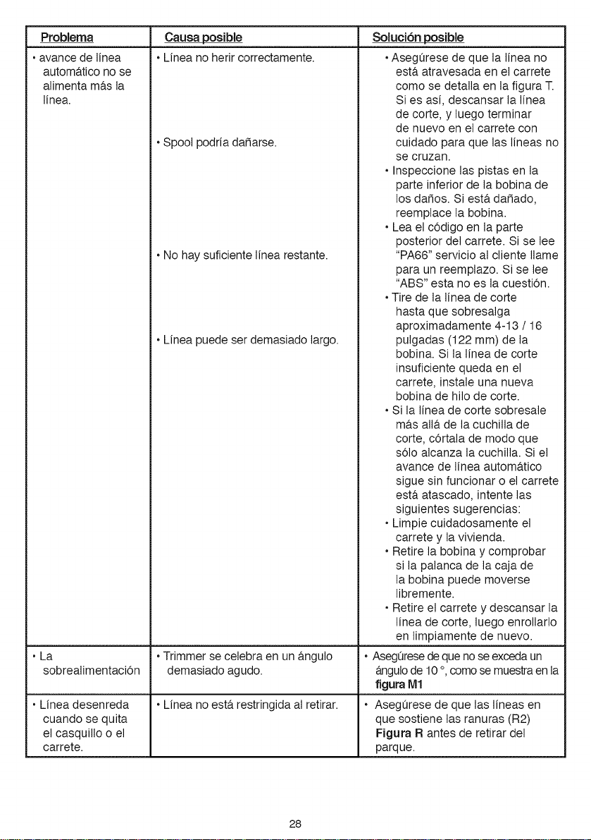
Problema
•avance de linea
autom&tico no se
alimenta m&s la
line&
• La
sobrealimentaciOn
• Linea desenreda
cuando se quita
el casquillo o el
carrete.
Causa posible
• Linea no herir correctamente.
• Spool podria dafiarse.
• No hay suficiente linea restante.
• Linea puede ser demasiado largo.
•Trimmer se celebra en un &ngulo
demasiado agudo.
• Linea no est& restringida al retirar.
SoluciOn posible
•Asegerese de que la linea no
est& atravesada en el carrete
como se detalla en la figura T.
Si es asi, descansar la linea
de corte, y luego terminar
de nuevo en el carrete con
cuidado para que las lineas no
se cruzan.
• Inspeccione las pistas en la
parte inferior de la bobina de
los dafios. Si est& dafiado,
reemplace la bobina.
• Lea el cOdigo en la parte
posterior del carrete. Si se lee
"PA66" servicio al cliente Ilame
para un reemplazo. Si se lee
"ABS" esta no es la cuesti0n.
• Tire de la linea de corte
hasta que sobresalga
aproximadamente 4-13 / 16
pulgadas (122 mm) de la
bobina. Si la linea de corte
insuficiente queda en el
carrete, instale una nueva
bobina de hilo de corte.
• Si la linea de corte sobresale
m&s all& de lacuchilla de
corte, cOrtala de modo que
s01oalcanza la cuchilla. Si el
avance de linea autom&tico
sigue sin funcionar o el carrete
est& atascado, intente las
siguientes sugerencias:
• Limpie cuidadosamente el
carrete y la vivienda.
• Retire la bobina y comprobar
si la palanca de la caja de
la bobina puede moverse
libremente.
• Retire el carrete y descansar la
linea de corte, luego enrollarlo
en limpiamente de nuevo.
• Asegeresedequeno seexcedaun
&ngulode 10°,comosemuestraenla
figura M1
• AsegQrese de que las lineas en
que sostiene las ranuras (R2)
Figura R antes de retirar del
parque.
28

29

30

31

®
Product questions or problems?
1-888-3 1-45
Customer Care Hot Line
Get answers to questions, troubleshoot problems,
order parts, or schedule repair service.
Para respuestas a preguntas o problemas, y ordenar
TM
(R_Registered Trademark / Trademark of KCD tP, LLC in the United States, or Sears Brands, LLC in other countries
TM
(R)Marca Registrada / Marca de Fabrica de KCD IP, LLC en Estados Unidos, o Sears Brands, LLC in otros paises
32