operator'sl
manual.,
MODEL NO.
358,7r96170 '
.• , •%,j•
" !fl,WARN;NG:
read and follow all
Safety Rules, Precationsand
Operating Instructions, Fail-
ure to do so can result in
serious personal injury,
_/ , STCRRFTSMRN®t
r22.2CC GASOLINE EDGER
2 Cycle Engine
=Assembly
= Operation
Fuel Mix 16:1
=Maintenance
= Repair Parts "
i_Always Wear Eye Protection During Operation
.... : Sold by Sears. Roebuck and Co.,, Chicago. Ill. 60684 U.S.A._' •
666654-0108_t-01086: • - .
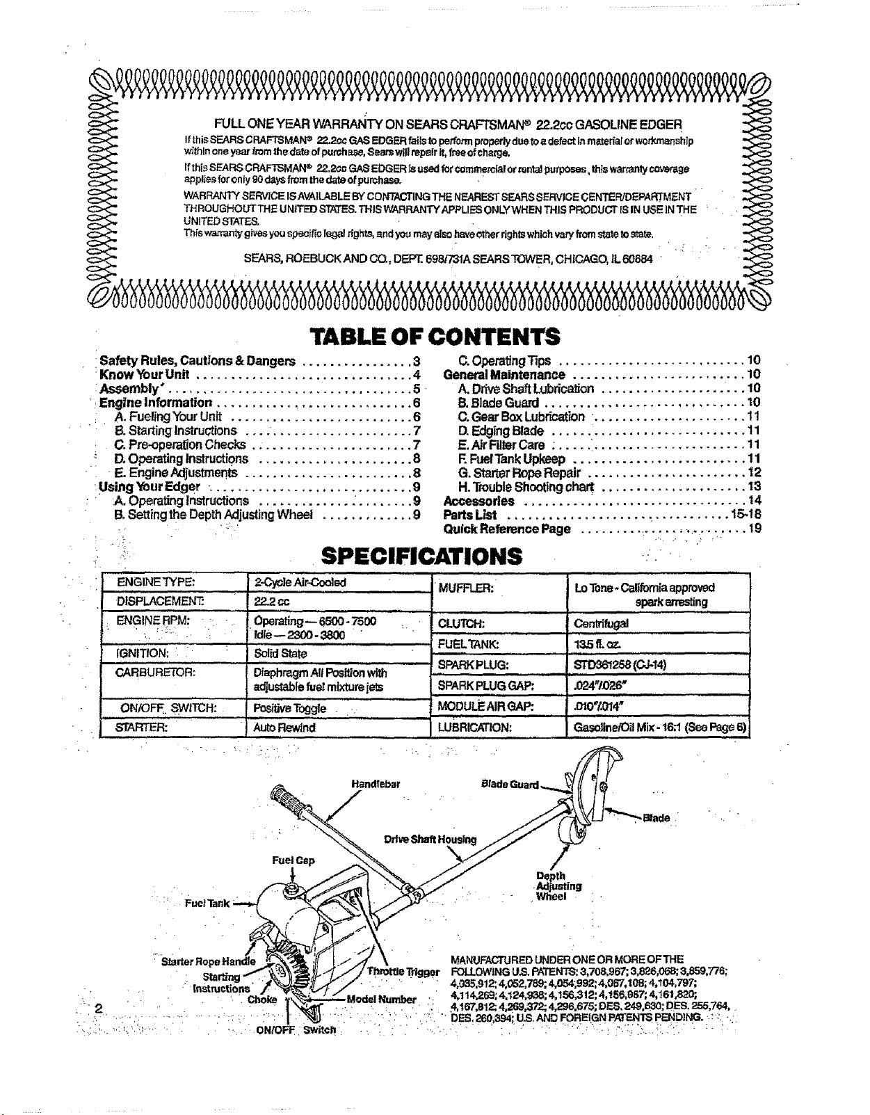
TABLE OF CONTENTS
• !Safety Rules,Cautions&Dangers ................ 3
•KnowYourUnit ............................... 4
:Assembly'. .................................. 5,
_.Engine Information ............................ 6
• A. FuelingYour Unit .......................... 6
B.StartingInstructions.... .................... 7
: C.Pre-operationChecks ....................... 7
D.OperatingInstructions ...................... 8
E.Engine Adjustments ........................ 8
:UsingYourEdger +............................ 9
• A, Opera_nglnstructions ' .9
13.SettingtheDepthAdjusting Wheet ............. 9
ENGINE TYPE:
DISPLACEMENT."
ENGINE RPM:
IGNITION:
CARBURETOR:
...........ON/OFF SWITCH: .
STARTER:
,,,, ,, • , ",
AutoRewind
SPECIFICATIONS
2-CycleAJr-Ooolad "................MUFFLER::
22_cc
Operating-- 6500.7500 :.. CLUTCH:
fdle-- 2300-3800 ..........
..... FUELTANK:
SolidState
......................SPARKPLUG:"
D_aphmgmAltPosPJonwith .......
adjustablefuetmixturejets SPARKPLUGGAP;.
u i
MODULEAIRGAP:
LUBRICATION:
(3.OperatingTips ........................... 10
GeneralMaintenance ......................... 10
A.DriveShaftLubrication..................... 10
B.BladeGuard............................. 10
C.GearBoxLubrication. ..................... 11
D.EdgingBlade ............................ 11
E,AirRlterCare ; ..... :...................... 11
F.FuelTankUpkeep ......................... 11
G.StarterRopeRepair ....................... 12
H.TroubleShootingchart ..................... 13
Accessories ................................ 14
PartsLiSt .................... _ .......... 15.t8
QUickReferencePage ......... :.............. .,. 19
, ' , .
LoTone-Californiaapproved
sparkarresting
Centd_gal
13,5g.<_
............
.024"i_26"
iiiiiiiiiiiiiii i i i
iiiiiiii ii ..................
Gasoline/OilMix-16:1(SeePage6)
Handlebar Blade Guard,.._ (( l_ '
'; Ddve,_rt H
Fuel Cap /
Depth
•Adjusting
_j_. " • MANUFACTUREDUNDER ONE OR MORE OFTHE
: 'StarterRope Handle rottleTdgger FOi.LOWING LI.S.PATENTS:3,708.967; 3,826,068; 3.859,776;
. . " " 4.035,912;4052,789; 4,054;g92;4,05"7,108;4,104,797;
•Model Number . 4.114.269;4.124,938; 4,156,312; 4.156,987; 4,161,820;
: . 4 167,812;4,269,372; 4 296,675; DF._,249,630; DES, 255,764,
" : " 2 ' " " '" " ......... : ': ...... : " M" :" " ' " '_ rr " DES 260,394iU.S AND FOREIGN PATENTSPENDING. _::
SAFETY RULES, CAUTIONS & DANGERS
Failureto observethe followingSafetyRules andPrecautions canresultin seriouspersonal injury.
A. KNOW YOUR UNIT
1, Read your Operator's Manual carefully until you
completely understandand followall safety rules,
precautions_ and operating instructions before
operating theunit.
2. Restrict your unit to users Whounderstand and
follow all safetyrules,precautions, and operating
instructions inthis manual,
13. PLAN AHEAD
1. Always wear eye protection. The
blade guard will not prevent rocks
and debris from being thrown or
ricocheting into the eyes and face
which can resultin loss of vision or sedous per.
sona/ injur_.
2. Dress safely in long pants and wear boots or
safety shoe_ Donotwearlooseclothing,jewelry,short
pants orsandals;orgobarefoot.
& Do not operate the unitwhen you aretired, ill, or
upset; or ifyouateundertheinfluence ofalcohol,
: drugs or medication.
4. Inspect the areato be cut, Removealtdebris and
objectsthatcouldricochet,be thrownorcouldother-
wisecauseinjuryordamageduringedging.
5. Keepchitdren,bystanders,andanimatsaminimum
_ :of30 feet (10meters) away when starting oroper-
ating theunit.
C. HANDLE FUEL WITH CAUTION
1. Eliminateallsoumes ofsparks orflame(incfuding
smoking, open flames, or work that could cause
sparks) in theareaswhere fuel ismixed,pouredor
stored.
2. Mix and pour fuel in an outdoor area; storefuel in
a cool, dry, well-ventilated place; and use an
approved, markedcontainer for allfuel purposes.
3. Do not smoke while handling fuel or while
• operating the unit.
• •4. Wipe up allspills before starting the engine.
5. Move at least10feet {3meters) awayfromfuel and
• fueling site beforestarting the engine.
D. OPERATE YOUR UNIT SAFELY
1. Do not use any attachment other than those
supplied and recommended bySearsfor usewit.h
this unit,
2. Inspect the entire unit before each usefor worn,
loose,missing ordamagedparts.Donotuseuntilthe
unitisin properworkingorder.
6. Make sure the blade stops turning when the
throttle trigger Is released and the engine runs
at idle speed. Forcorrection,referto "Carburetor
Adjustments"page8.
7. Stop the engine and let the unit cool off before
removing the fuel cap and refueling. Always
replacethefuel cap securely.
8. Keep all parts of your bodyaway from the blade
when startingor runningtheengine.
9. Avoidbodilycontact withthe muffler. Usecaution
whenchangingoperatingpos_onsThe muffler area
can be hotandcause seriousbums.
10. Do nctoverreach.Keepfirmfootingand balanceatall
times
11. Usetheedgerfromyourrightsideonly.Keepyour
lefthandonthehandlebarand yourrighthandonthe
powerunithandle.
Directthe dischargeof debds away from people,
animals, glass, and solid objects such as trees,
automobiles,walls,e_c,asthe unit isbeing operated
12. The fastturningblademaycauserocks,dirt, or sticks
to be thrown or to dcochetwhich may hurt people or
animals, breakglass,or causeotherdamage
13. Do not use the edger on graveled surfaces or in
extremely muddyareas.
14. Always pushthe unit slowly over rough ground.
StayaJertforunevensidew_ks,holesinterrain,orother
similar conditions
15. Followthestepsbelowifthebladestrikesaforeign
object or ffthe unitoperatesabnormally. Stopthe
engine, disconnectthe spark ptug and inspectfor
damage Donotuseuntilthe unitisinproper workJng
• order
16. Stop theenginewhen theunitisnot in use. Donot
leavea runningengineunattended.
17. Useonly forjobsexplained inthis manual.
E. MAINTAIN YOUR UNIT PROPERLY
1, Haveallservice other then the items listedin this
manual performed byyourSearsService Center,
2. Maintainthe unitaccording torecommended pro-
cedum,_
3. Disconnect the spark plug l_fom performing any
adjustment, inspectionor maintenanc_ _pt for
: carburetoradjustment.
•4. Be certain the blade will not contact any object
before making engine adjustments.
5. Use only genuine replacement parts as recom.
: mended bySeam. Theuseofanypart,or accessory
notspecifically recommendedforthisunitmaycreate
a hazardandlorvoid_ur warranty.
; 6. Always drainfuel from thetank beforestoring the
3. Keep the handles free of oil and fuel. unitfor 30 daysor more,
4. Neverstartorruntheengineinsideaclosedroom ..... 7. D0notstomtheunitorfuelinactosedareawhere
• _ fuelvaporscanreachsparksoranopenflame from
orbudding.Exhaustfumescontaindangerousearbon • ; hot water heaters,.furnaces,etc.
, monoxide.
5. Never operetethe edger without the blade guard : 8.Storeinadryareaoutofthereachofchildren.•
and handlebar securely in place, r J. _ ........ "
r
SAVE THESE INSTRUCTIONS
KNOW YOUR UNIT
A, INTRODUCTION ..... _':
Yourunit willedgesidewalks,drivewaYsandcurbspre-
ciselyand neatly. ' '
Special Festumsinclude:
* 7" inch reversibleblade
- Adjustabledepthcontrolupto2 inches
1800blade shield
* Extendedhandlebar
- Total weight- 14.5tbs.
,i , ,,, ,,,,,,,,,
B, UNPACKING INSTRUCTIONS _
1.Remove contents from the carton ifyo u havenot
doneso.
2. Checkpartsagainstthe listbelow.
3.:Examinepartsfor damage..:
4. Notify your Sears Store immediately if a part
ismissing or damaged.
NOTE: A rattlelike noisein a powerheadwith an
emptyfueltankisanormalcondition,causedbythe
filtermoving againstthewall ofthe emptytank.
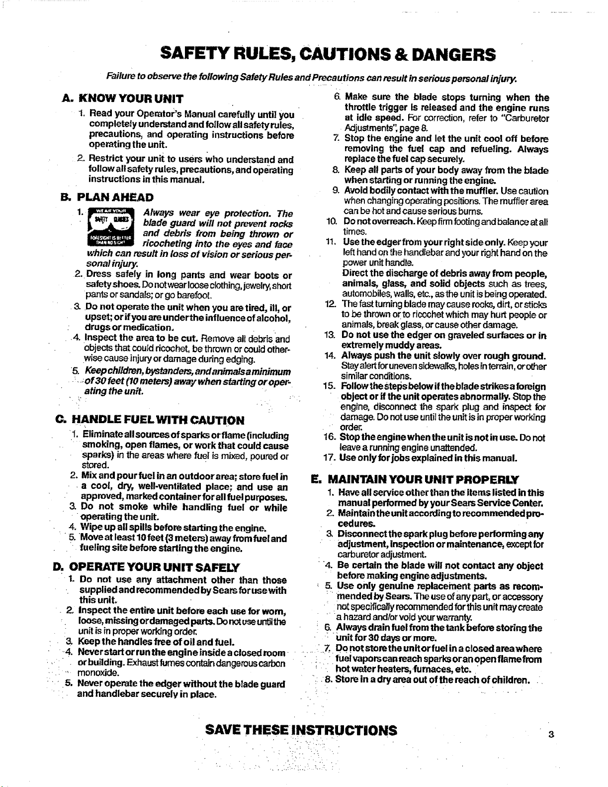
KEY CARTON CONTENTS: QT_
1 Engine 1
2 . .Drive Shaft Assembly " " 1
3 , Gear BccdBl_e &Guard/Depth Wheel
Assembly .... 1
,4 Handlebar 1
5 Engine Oil ........ 1
6 Grease " - " 1
"_7-, LoosePartsBag(notshown) 1
'.,_.. LOOSEPARTSBAGCONTENTS:
7 Bracket-Handlebar :- " • _ 2
: " r r 8" ' P_ ".Bolt - I/4 - 20Xt-1/4"- Clamp & --
. . .. Handlebar., 2
•!0.
11
12
13
14
15
16
L_k washer-1/4. HandlebarBracket
Blade
Washer- 7/16-Blade
Nut-7/16-14- Blade
Clamp- EngineShroud
Bolt_Clamp t14.20 x9116"
Nut- 1/4-20- Clamp
Nut- I/4 -20 Brecht &Handlebar
Operator's Manual(notshown)
.2
1
1
!
!
1
_TATEAND LOCAL
ORDINANCEREQUIREMENTS "
Yourengine is equipped with a temperature limiting
muffler and spark arrestingscreen which meets the
requirements of CaliforniaCodes 4442 and 4443. All
U.S.ForestLandandthestatesofCalifomia_Maine,Oregon,
andWashingtonreqL_rebylawthst¢_ertainInternalcombus-
! tionenginesoperatedonfoP.st,brush,andgrasscovered
: amesbeequippedwithatemperaturefimitingmufflerand/or
sparkarrestingscreen.Ifyou operatean intern!!corn-
: bustlonengine in astate or localewhe_ suchregula-
tionsexist, youarelegallyresponsibleformaintsining
theoperating conditionoftheseparts,Pailuretodoso
can subject youto liabilityorto a fine,.... . ' '
r, . ,
" ' "J _k
:141"
. ,. . •
ASSEMBLY
Your Operator's ManuaJhas been developed to help you
assemble the unit and tounderstand its safe operation. It is
important that youreadyour manual completely to bacome
familiar with the unit before you begin assembly.
A, PREPARATION
1. READ YOUR OPERATOR'S MANUAL
2. Tools you will need: ' •
a. Slotted Screwdriver _'_
b.
11116inchwrench
(2)7/16inchwrenches
OF
(2)Adjustablewrenches
Figure 1
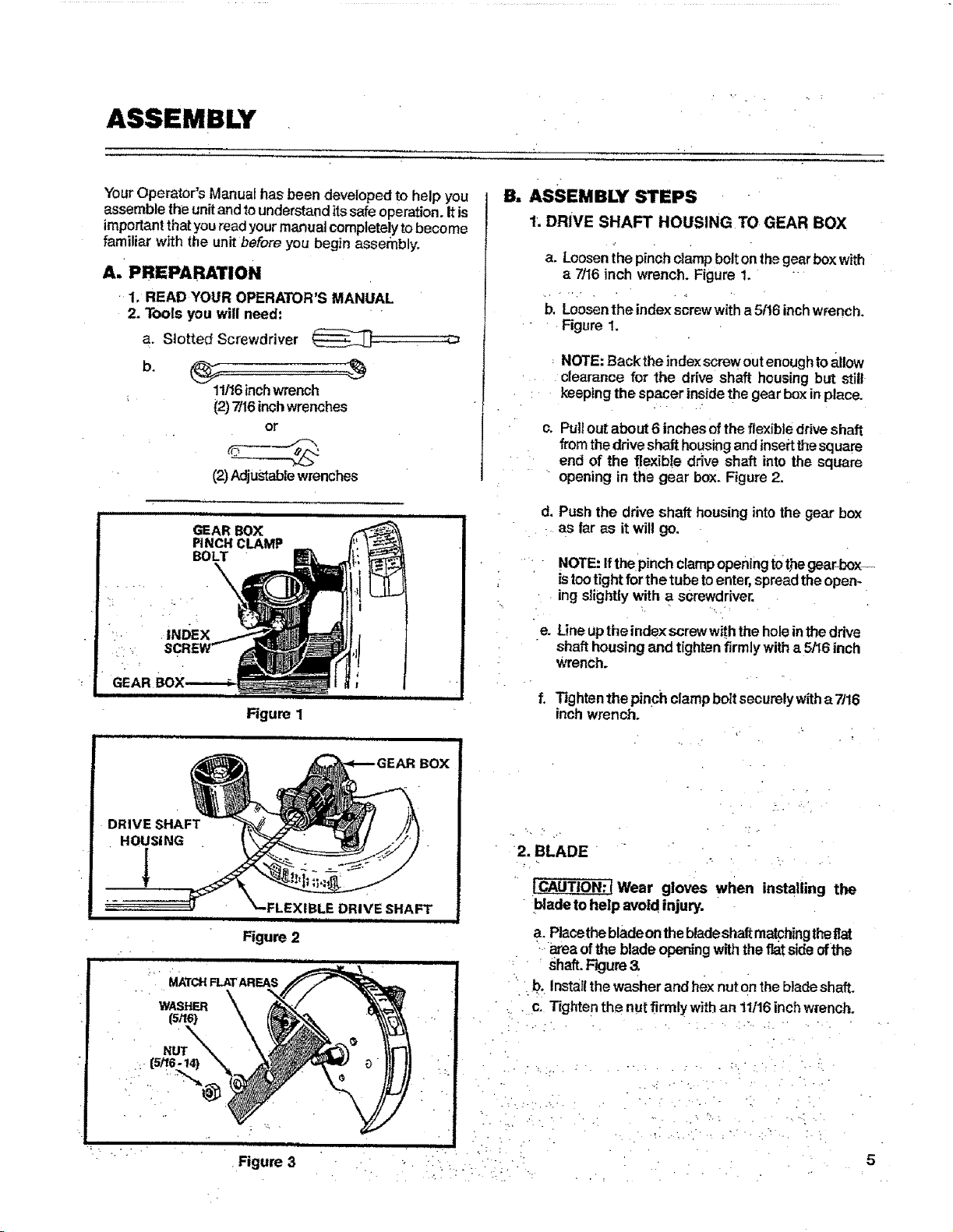
B. ASSEMBLY STEPS
1. DRIVE SHAFT HOUSING TO GEAR BOX
a. Loosenthe pinch clampbolt onthegear box with
a 7116inch wrench. Figure 1.
b, Loosenthe index screwwith a 5f16inch wrench.
Figure 1.
NOTE:Backthe indexscrewoutenoughtoallow
clearance for the drive shaft housingbut still
keeping the spacer insidethe gear box in place.
c. Pull out about 6 inches of the flexibleddve shaft
from the driveshaft housingand inse_tthesquare
end of the flexib!e drive shaft into the square
opening in the gear box. Figure 2.
d, Push the drive shaft housing into the gear box
as far as it will go.
" NOTE:IfthePinch clampopeningl:0thegear-box-.-
istootightforthetube toenter, spreadtheopen-
ing slightly with a screwdriver.
• L , ':
e. Lineuptheindexscrewwiththe holeintheddve
shafthousingand tightenfirmlywitha 5/16inch
Wrench.
f, _ghten the pinch clamp bolt securely witha 7/16
inchwrench.
DRIVE SHAFT
HOUSING
NUT
Figure 3
DRIVE SHAFT
iii iiii ii i
2. BLADE
Wear gloves when installing the
bladeto help avoid injury.
a. Placethebladeonthebladeshaft matchingtheflat
area ofthe blade openingwiththeflat sideofthe
Shaft.Figure
" b. Installthe washerand hex nut on the bladeshaft.
• c- Tighten the nutfirmty with an 11116inch wrench.
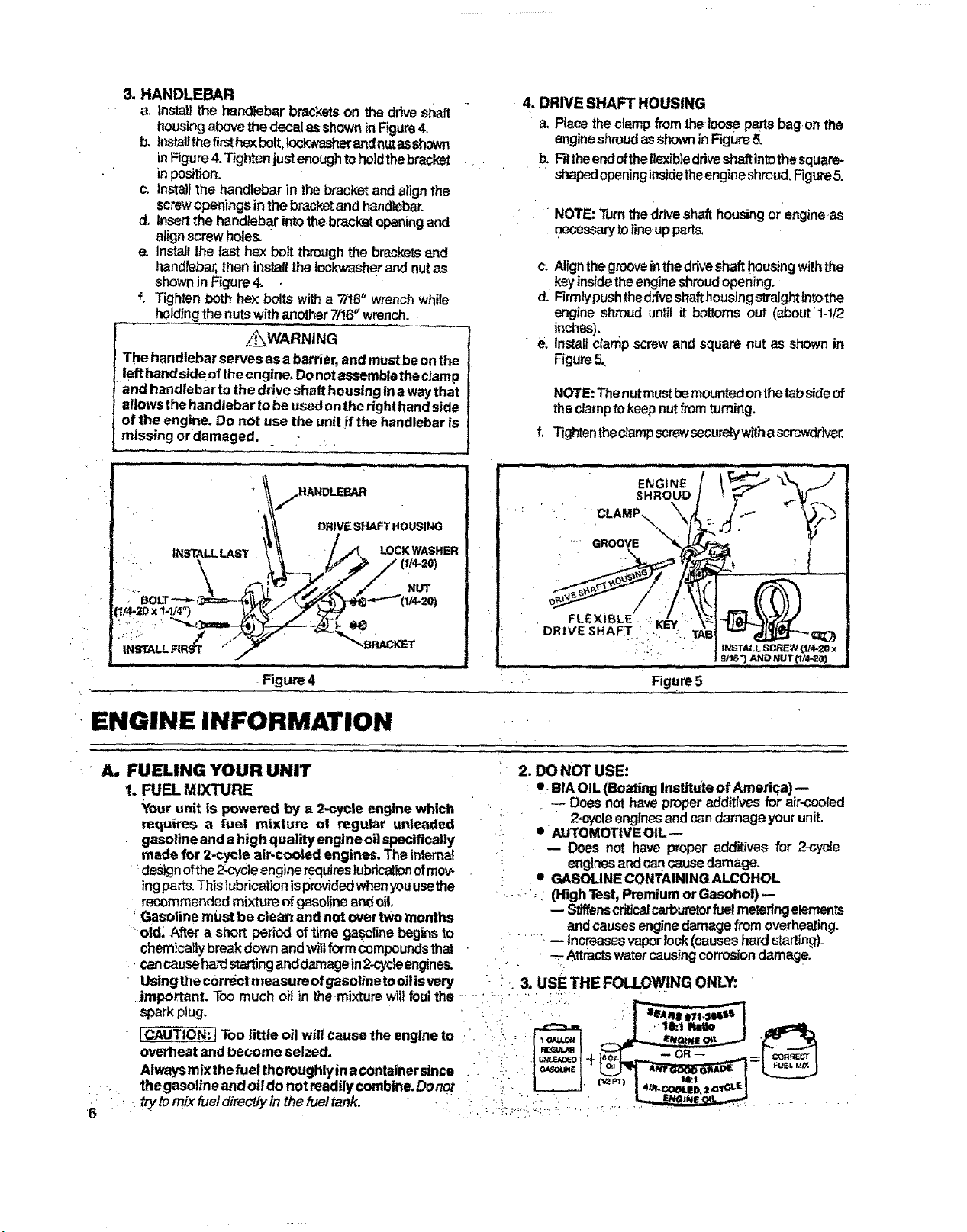
3.HANDLEBAR
a. installthe handlebarbracketson the driveshaft
housingabovethedecal asshowninFigure4.
b. Installthefirsthexbolt,lockwasherandnutasshown
inFigure4.Tightenjustenoughtoholdthebracket
inposition.
c. lnstatithe handlebarin thebracketand alignthe
screwopeningsin thebracketandhandlebar.
d. Insertthehandlebarintothebracket openingand
alignscrewholes.
e. Installthe tast hexboil throughthe bracketsand
handlebar,then installthe Iockwasherand nutas
ShOWn Jn Figure4.
f. Tighten bothhex boltswith a ?/16r' wrenchwhile
holdingthe nutswith another7/16"wrench..
z_WARNING
The handlebar servesasa barder,and mustbeonthe
lefthandsideoftheengine,Donotassembletheclamp
'and handlebar tothe drive shafthousing inawaythat
allowsthehandlebar tobeusedonthe righthandside
of the engine. Do not usethe unitif the handlebaris
missing or damaged.. ;
-.4. DRIVE SHAFT HOUSING
"a. Placetheclampfrom theloose partsbag,onthe
engineshroudasshowninFigure5.
b. Rttheendoftheflexibledriveshaftintothesquare-
" .... shapedopeninginsidetheengineshroud.Figure5.
. " NOTE:Turnthe driveshafthousingorengineas
. necessarytolineupparts.
c. Alignthegroovein thedriveshafthousingwiththe
keyinsidetheengineshroudopening.
d. Firmlypushthedriveshafthousingstraightintothe
engine shroud until it bm'toms out (aboutl-tt2
inches).
• e. Installclamp screwand square nut as shown in
Figure5.
NOTE:Thenutmustbemountedonthetabsideof
theclamptokeepnutfromturning.
f, Tightentheclarnpscrewsecurelywithascrewdr'rver.
Figure 4 Figure5
. ,,,,,,,,, •
ENGINE INFORMATION ....
• A, FUELING YOUR UNIT
1. FUEL MIXTURE
Your unit is powered by a 2-cycle engine which
requires a fuel mixture ot regular unleaded
gasolineand e high quality engine oilspecifically
made for 2*cyele air-cooled engines. Theinternal
designofthe2-cycleenginerequireslubricationofmov- .
ingparts.Thislubricationisprovidedwhenyouusethe
• recommendedmixture ofgasolineand oil,
' Gasoline mustbe clean andnot overtwo months
'old; After a shortperiodoftime gasolinebeginsto
chemicallybreakdown andwillformCompoundsthat •
cancausehardstartinganddamagein2-cycleengines.
Usingthe c0rrectmeasure ofgasolinetooilisvery .
• 2. DO NOT USE:
• .!- Bib,OIL(Boating Institute of America)--
Doesnot haveproperadditives forair-cooled
: " 2-cycleenginesand candamageyour unit.
,!. .- • AUTOMOTIVEOIL
•: , -- Does not have properadditivesfor 2-cycle
engir_sand can_ damage.
• GASOLINECONTAININGALCOHOL
..--.., (HighTest,PremiumorGasohol)
-- Stiffenscriticalcarburetorfuelmeteringelements
and causesenginedamagefrom overheating.
....... ,-- increasesvaporlock(causeshard starting).
' _ Attractswatercausingcorrosiondamage.
. 3. use THE FOLLOWING ONLY: r
.important. Toomuch oil in themixture wiltfoul-the--. - :.--. • -.' • ._i:. " _
sparkplug. " ' : -:; t I
TOO little oil will cause theengineto ..".' _r'_,,'. _ _ __ '_
overheatandbecomeselzed. '::: + I
Alwaysmixthefuelthoroughlyinacontainersinca .. !:- .. :J_ou,, I _L_,7 *_A__..I--L_
:.. thegasolineandoildonotreadilycombine.Donot :i,'.. L___J
6 :'• ttYt°mixfueldirectlyinthefueltank" "•. "_ ' _ ::'_r_'_'_'_' ;';'''_ _:." :" '' r_ '__ .......
4. HOW TO MIX FUEL AND FILL TANK
a. Pour 1/2 gallon of. gasoline into an approved,
markedcontainer.Donottry tomix oilandgasoline
directlyin thefueltank.
b, Add entiremeasureof EngineOil.
c. CovercontainertightEyandshakefor one minute.
d. Add remainderofgasoline.
e. Covercontainer tightlyand shake again.
f. Removethefuelcap.Referto"Specifica_ons;'page
2, forfuelcap location.
g. Fillthe tankusing a spout or funnel
h. Reinstallthefuel cap securely.
5. IMPORTANT POINTS TO REMEMBER
a. Useonly recommended fuel mixtures.
b. Eliminateaitsources of sparks orflame in the
areas where fuel is mixed, poured, or stored,
Thereshouldbenosmoking, open flamesorwork
.thatcou{dcausesparks.
c. Useanapproved, marked containerfor all fuel
purposes.
d. MiXandpourfuel in anoutdoor area. Storefuel
in a cool, dry, well-ventilated place. Gasoline
vaporsare harmful toyour healthand can cause
serioushazards,such asexplosion and fire. Usea
funnelor spoutwhenpouring fuel.
e. Wipeup all fuelspills beforestartingthe engine.
f. Moveat least 10feet (3 meters) awayfrom fuel
andfueling sitebefore starting the engine.
B. STARTING INSTRUCTIONS
1. IMPORTANT POINTS TO REMEMBER
a. Stand intheoperatingposition (Figure 12,page
9 )andtilt theunitto theleft, Whlfethe engineis
beingstartedtopreventtheblade fromcontacting
thegroundoranyobject.
b. Pullthestarterrope quickJyandsharptybut no
morethan 10timestoavoidfloodingtheengin_
ifengine floods,pushchokeknob in fully and pull
starterropesharplyuntilengineruns.Donotletthe
starterropesnapbackbetweenpulls.Holdtheham
die and lettherope rewindslowly. , r
if the blade does not turn when the engine is
accelerated, makesurethedriveshafthousingis
propedyseatedintheengineshroud.Referto"Drive
Shaft& DdveShaftHousing",page6.
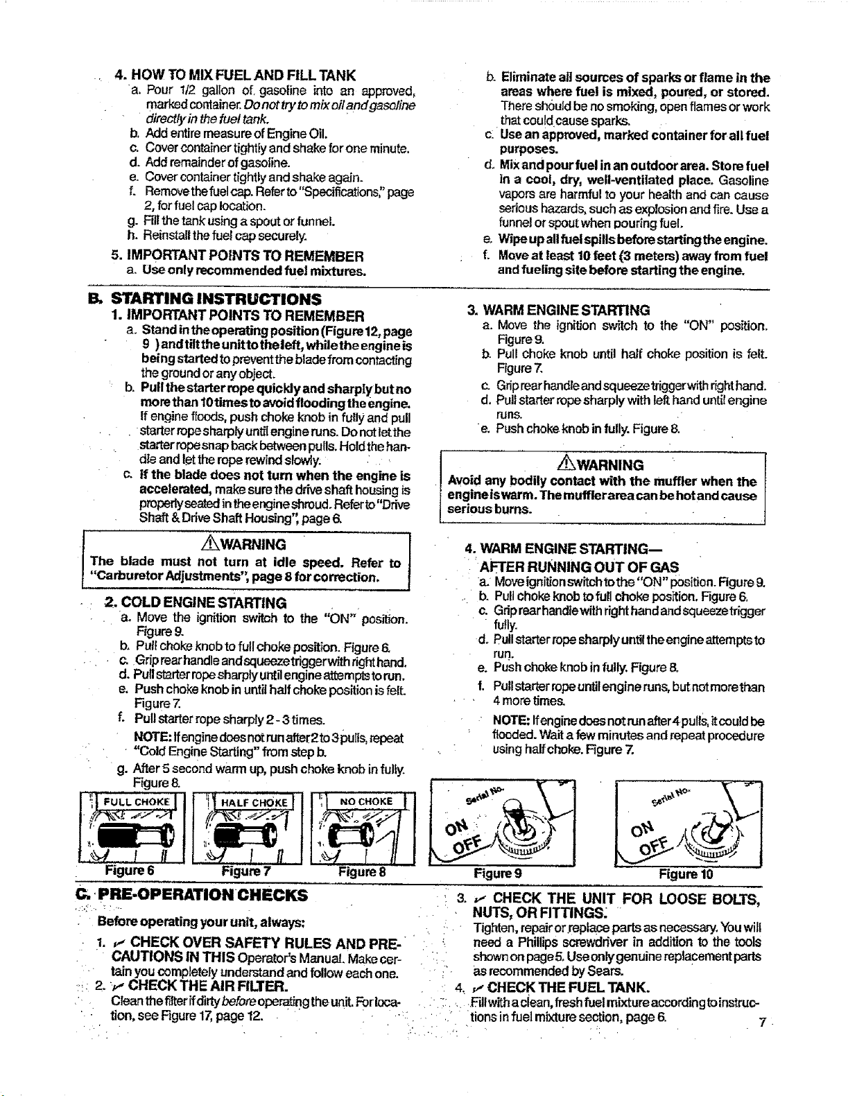
3. WARM ENGINE STARTING
a. Move the ignitionswitch to the "ON" position.
Figure9.
b. Pull choke knob until half choke position is felt.
Figure7.
c. Griprearhandleandsqueezetriggerwlthrighthand.
d, Pull starterropesharplywith lefthand unti!engine
rUnS. .'
e. Pushchokeknob in fully. Figure8.
_W_NWNG r"
Avoid any bodily contact with the muffler when the
engineis warm.The mufflerarea canbehotandcause
serious burns.
i_WARNING
The blade must not turn at idle speed. Refer to
"Carburetor Adjustments'; page 8 for correction.
2. COLD ENGINE STARTING
a. Move the ignitionswitch to the "ON" position.
Figure9.
b. Pullchokeknobto fullchokeposition.Figure6.
Gdprearhandleandsqueezetdggerwithdghttrend.
d. Pullstarterropesharply untilengineattemptstorun.
e. Pushchokeknob inuntilhalfchokepositionisfelt.
Figure7.
f. Pullstarterropesharply 2- 3 times.
NOTE:Ifenginedoesnotrunafter2to3putts,repeat
"Cold Engir)eStarting" fromstepb.
g. After 5 second warmup,pushchol_ knob infully.
4. WARM ENGINE STARTING--
AFTER RUNNING OUT OF GAS
a. Moveignitionswitchtothe "ON" position.Rgure9.
.. b. Pullchokeknob tofullchoke position. Figure6.
c. Gdp rearhandtewithrighthand andsqueezetrigger
fully.
d. Putlstarterropesharply untilthe engineattemptsto
run.
e. Pushchokeknobinfully. Figure8.
f. PullstarterropeuntJlengineruns,butnotmorethan
. 4 moretime_
NOTE:Ifenginedoesnotrunafter4pulls,itcoutdbe
flooded.Waita fewminutesendrepeatprocedure
usinghalfchoke.Figure7.
Figure 7
Figure 8
i•i.
I
Figureg
J
" _ _|r
Figure 10
C* PRE-OPERATIONCHECKS : 3. ,! CHECK THE UNIT FOR LOOSE BOLTS,
r" :'::" _ : ''" : NUTS, OR FITTINGS; '
• Beforeoperating yourunit, always: : Tighten,rep_r or replasepartsas necessary.Youwill
1. _--CHECK OVER SAFETY RULES AND PRE- " _ need a Phillipsscrewdriverin addition to the tools
CAUTIONS IN THIS Operator'sManual.Makecer- " shownonpageS,Useontygenuinereplacementparts
• lain youcompletelyunderstand andfollow eachone. • _- asrecommendedbySears.
2. _,, CHECK THE AIR RLTER. : 4_ ,I CHECK THE FUEL TANK.
. Cleanthefilterifdirtybeforeoperaf]ngtheunit.Forloca- " ' , .._lfvi=thaciean, freshfuelmixture accordingtoinstruc-
' • tion, see Rgure17,page 12..... :. " .. tionsin fuel mixture section, page 6. 7.
•D. OPERATING INSTRUOTIONS
Formaximum performanceandefficiency:
1. AJwaysaccefemtetheengine tothe desiredspeed
beforecutting.
2. Never operatethe engine at a higher speedthan
necessary.
E' ENGINE ADJUSTMENTS
L CARBURETOR ADJUSTMENTS
The carbum=torhas been carefullyadjusted at the
Pactory+Due to changesin altitude and operating
conditions,yourcarburetormay requireadjusting.To
maketheadjustment,followtheprocedurebelowvery
caretutly.
: '+
_pr
r
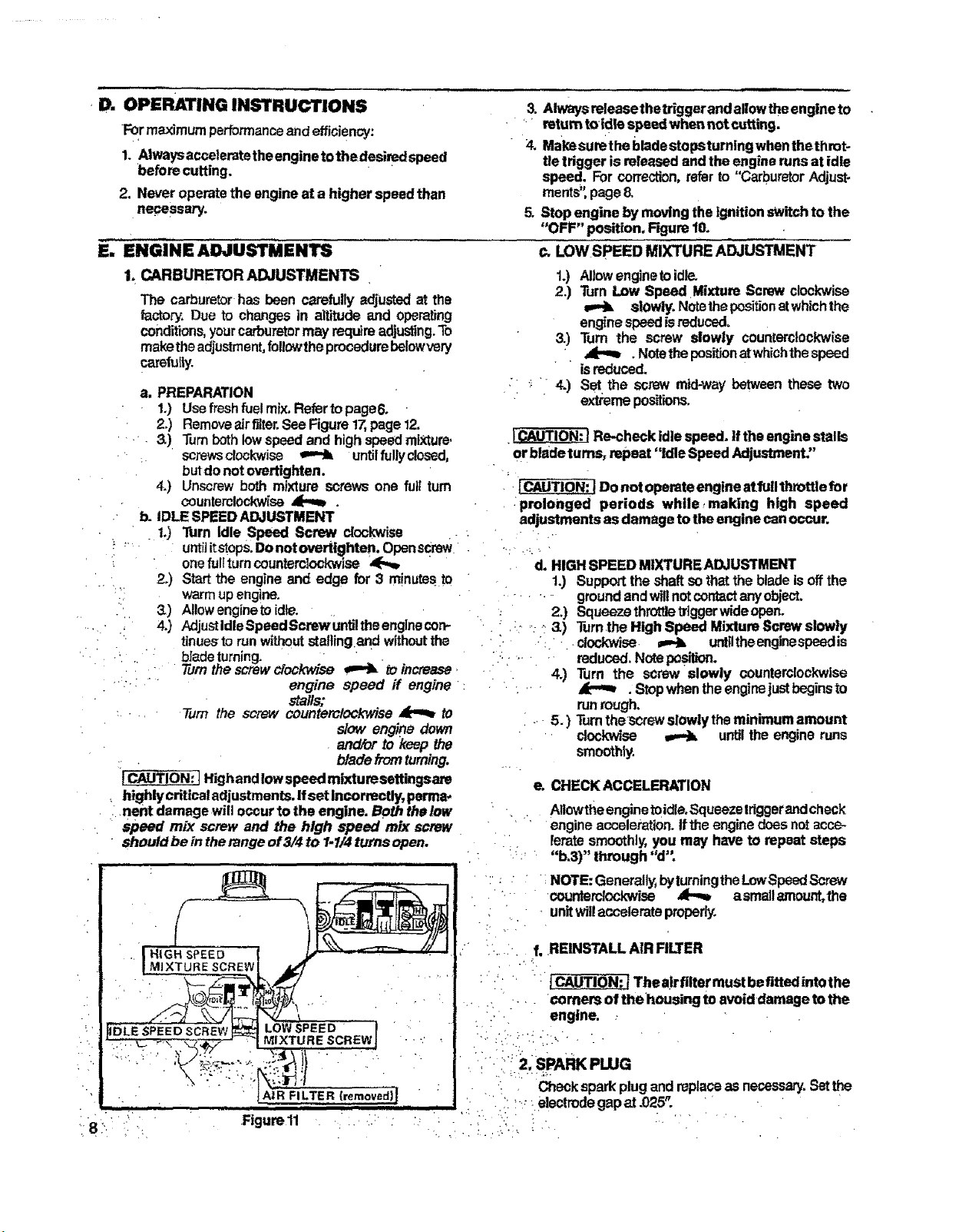
a. PREPARATION
1.) Usefreshfuelmix,Refertopage6.
2.) Removeair filter.See Figure17,page12.
•,. 3.) Turnbothlowspeedand highspeedmixture.
: scows clockwise _ untilfully dosed,
butdo notovertighten.
4.) Unscrewbothmixture screws one fullturn
countemlockwise_ .
. b. IDLESPEEDADJUSTMENT
_ 1,)
2J
. i1,11,i .
3. Alwaysreleasethetriggerand allowtheengineto
return toidle speed whennot cutting.
4. Makesumthe bladestopsturningwhenthethmt-
tie trigger isreleasedand the enginerunsat idle
speed. Forcorrection,referto "Carburetor Adjust.
rnents';page8.
5. Stop engine by moving theignitionswitchto the
"OFF" position. Rgure t0.
c, LOW SPEED MIXTURE ADJUSTMENT
1.) Allow enginetoidle,
2.) Turn Low Speed Mixture Screw clockwise
slowly. Notethepositionatwhichthe
enginespeedisreduced.
3.) Turn the screw slowly counterclockwise
. Notethe positionatwhichthespeed
isreduced.
:_" 4.) Set the screwmid-way betweenthese two
extremeposit_on_.
_)
4.)
ICAUTION:IRe-check Idlespeed,if theenginestalls
or bladetums, repeat "idle SpeedAdjustment"
Do not operateengine atfutlthrottle for
:prolonged periods while making high speed
adjustments asdamage to theengine canoccur.
Turn Idle Speed Screw clockwise
untiiitstops.Donotovertighten.Openscrew :. ' ... . / i .
onefulfturn countemtockwise,<-._ ...... d. HIGHSPEED MIXTUREADJUSTMENT
Startthe engine and edge for 3 minutesto . 1.) Supporttheshaftsothatthe blade isoffthe
warm upengine. • " •........ groundandwillnotcontactanyobject.
Allowengineto idle,
AdjustldlsSpeedScrewuntiltheenglnecon- * : 2.) Squeezethrottletriggerwideopen.
+. : , ,.--_3.) Turn.theHigh Speed MixtureScrew slowly
tinuesto run without stallingand wtthoutthe . "i. : : .. clockwise, _ untiltheenginespeedis
bfadeturning. " ' i:: : .... . "+ reduced,Noteposition.
lure thescrewclock_+se _ _ increase+ .. 4.) Turn the screw slowly counterclockwise
engine speed if engine : + ' " , - _ .Stopwhentheenginejustbeginsto
stalls,"
.... Turn the screw counterctock_se _ tO
slow engine down
and/orto keepthe
: . bladefromturning.
1CAUTION: ]Highandlowspeed mixtureeettingsare
highlycriticaladjustments. Ifset incorrectly,psrma-
:.nent damage will occurtothe engine. Boththelow
speed mix screw and the high speed mix screw
" should be in the range of 3/4 to 1.1/4 turns open.
runrough.
..- 5. ) Turnthescrew slowlytheminimumamount
' cloclodse _ untilthe engine runs
smoothly.
e. CHECK ACCELERATION
• . Allowtheenginetoidie, Squeezeldggetandcheck
' + engineacceleration. Ifthe engine doesnotacce-
AtR FILTER
Figure11
leratesmoothly,you may have to repeat steps
"b.3)" through "d"
NOTE:Generally,byturningtheLowSpeedScrew
counterclockwise _ a smallmount, the
• unitwillaccelerateproperly.
:*....... f. REINSTALL AIR RLTER
:: ' :_Thealrflltermustbeflttedintothe
comers of thehousing to avoiddamage tothe
L.. engine..-
: ,.L:/ '! i :._.+' ++
, i"-i' 2:SPARK PLUG
Checksparkplugand replaceas necessary.Setthe
...... :electrodegapat .025".
• r , r ,
USING YOUR EDGER
A. OPERATING INSTRUCTIONS
1. Read your Operator's Manual. Make certainyou
• completely understandand follow a_lsafety rules,
precautions, and operating instru_ons before you
operatethe unit
2. Always wear eye protection. The
blade guard will not prevent rocks
and debris from being thrown or
ricocheting into the eyes and face
which can result in loss of vision or serious per-
sonalinjury.
3. Dress safely in long pants and wear boots or
safetyshoes.DonotwearIooseclothing,jewelry,Short'
pantsorsandals; orgo barefoot.
4. Check the unit before operation. Lookfor worn,
loose,missingordamagedparts.Donotuseuntilthe
unitisinproperworkingorder.
5. Inspect the area to be cut. Removeall debrisand
objectsthat could ricochet, be threvmorcould other-
wisecauseinjuryor damage during edging.
& Keep children, bystanders, and animals safely
away.Beforesta_ng ffTeengineandduringoperation,
make certainpeople and animals are asafe distance
;away from the work area-- a minimum of30 feet(10
meters)
:r_. Tilt the bladeto the left while the engine isbeing
• ,started. ThiswillhelppreventthebJadefrommaldng
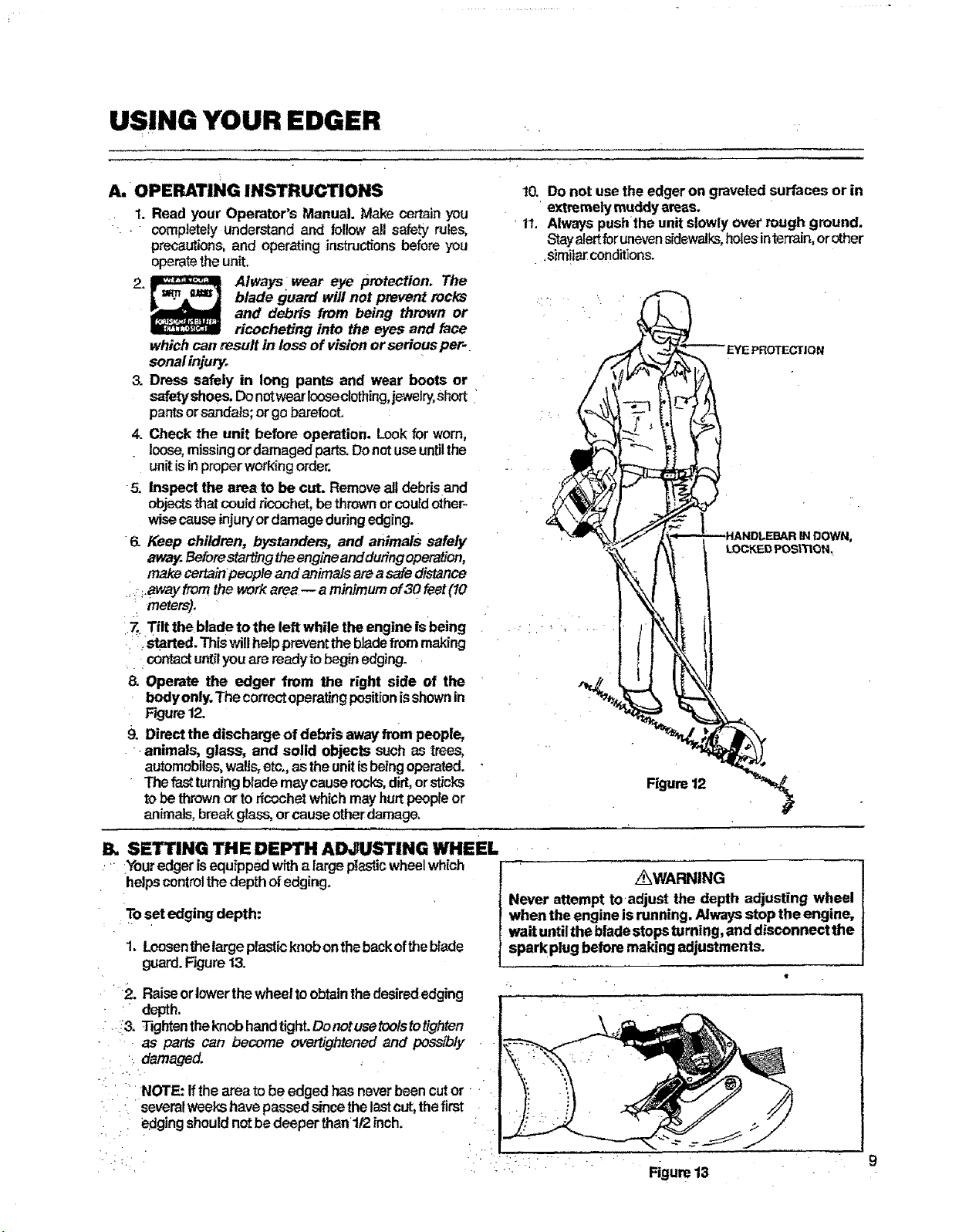
.... contactuntilyouare readytobegin edging.
& Operate the edger from the right side of the
bodyonly.The correctoperatingpositionisshownin
Ftgure12.
9. Directthe discharge of debris awayfrom people,
animals, glass, and solid objects such as trees,
automobiles,watis,etc.,as theunitisbeingoperated.
Thefa_ turningblademay causerecks,dirt,orsticks
tobethrownor toricochetwhichmay hurtpeopleor
animals,breakglass,orcauseotherdamage,
10. Do not use the edgeron gravetedsurfaces or in
' extremelymuddy areas.
11, Always pushthe unitslowly over rough ground.
Stayalertforunevensidewalks,holesinterrain,orother
,simita[ conditions.
. LOCKED POStTtGN_
il. SETTING THE DEPTH ADJUSTING WHEEL
_YOUt"edgerisequippedwith a large p_asticwheelwhich
helpscontrolthedepthofedging.
. Tosetedging depth:
1. Loosenthelarge pisstic knob ontheback oftheblade
guard. Figure 13.
.... _2. Raiseorlowerthe wheelto obtainthedesirededging
depth
i!& Tv3htentheknobhandtight`Donotusetoolstotighten
as parts can become ovettightened and possibly
• damaged.
NOTE: If the area to be edged has neverbeen cutor •
: severalweeks havepassedsince the lastcut,thefirst
: , edgingshould notbe deeperthanl/2 inch.
..... _WARNING
Never attempt toadjust the depth adjusting wheel
when the engine is running. Alwaysstop the engine,
wait untilthe bladestopsturning, and disconnect the
spark plug before makingadjustments.
Figure13
C. OPERATINGTIPS
Asyou becomefamiliarwithyouredger,youwillbeai0teto
determineyourownpaceforusingit.Conditionssuchas
depthofcutandmaterialbeingcutwillregulatethespeed'
andtimerequiredforyouredgingjob.
• i. Increasetheenginespeadbeforapiaclngtheblsde
in the cut. AllowengInetowarmupforone minute
beforeyoubeginedging,
2. RuntheengineatfullthmtUewhilecuffingforbast
operation,
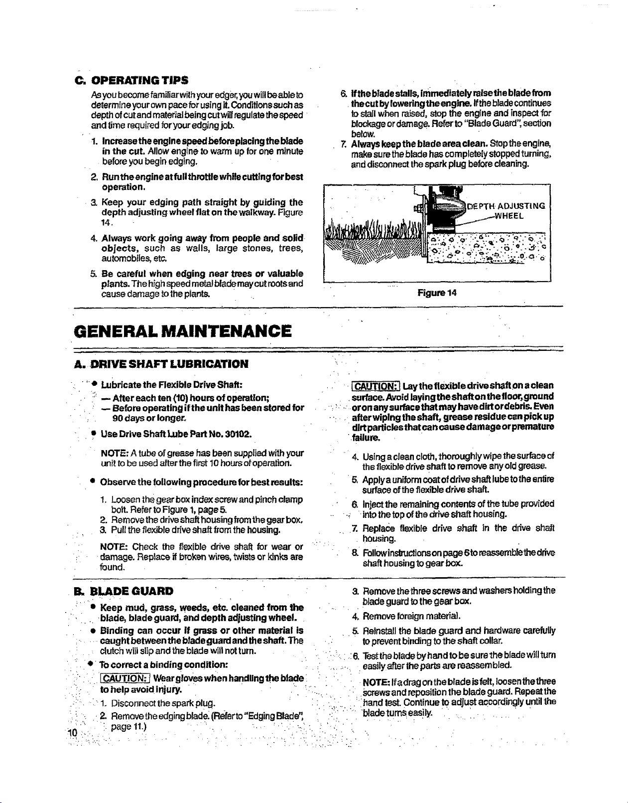
.3. Keep your edging path straight by guiding the
depth adjustingwheel fiat onthewalkway.Figure
14.
4. Always work going awayfrom people and solid-
obiects, such as walls, large stones, trees,
automobiles, etc,
5. Be careful when edging near trees or valuable
plants.The highspeedmetalblademaycutrootsand
causedamagetotheplant_
6. ifthe bPadestalls,immediatelyraisethebladefrom
thecutbylowering theengine,ifthebladecontinues
tostallwhenraised,stopthe englneand inspectfor
blockageordamage.Referto"BladeGuard',section
below.
7. Alwayskeepthe bladeareaolean. Stoptheengine,
makesurethebladehascompletelystoppedturning,
anddisconnectthespark plugbeforecleaning.
DEPTH" ADJUSTING
Figure14
GENERAL MAINTENANCE
A. ,DRIVE SHAFT LUBRICATION
' o Lubricatethe Rexible DriveShaft:
;;:-- After eachten(10)hoursof operation;
. "• -- Before operating ifthe unithas beenstoredfor
• 90daysor longer.
/ |CAUTIONi tLaythe flexible driveshaft0naclean
surface.Avoidlayingtheshafton theflo0r,ground
, _: oronanysurfacethatmayhavedirtordebd_Even
..... afterwiplngtheshaft, grease restduecanpick up
• UseDriveShaft LubePartNo. 30102.
NOTE:A tubeofgreasehasbeensuppliedwithyour " r
unittobe usedafterthefirst 10hoursor=operation.
• Obser/e the following precedurefor bestresults:
1=Loosenthegearboxindexscrewandpinchclamp
bolt. Refer toFigure1,page5-
2. Removethedriveshafthousingfromthegearbox.
3 PulttheflexJbledrfveshaftfromthehousing, ..
• ' NOTE: Check theflexibledriveshaftforwearor '"
-. .damage.Replaceifbrokenwires,twistsorkinksare
found.
• B,, |LADE GUARD
,:" • Keep mud, grass, weeds, etc. cleanedfrom the
:. .. blade, bladeguard, anddepth adjustingwheel. •
• Binding can occur if grass or other material is
;...... eaughtbetween thebtadeguardandtheshaft.The
dirtparticlesthatcan causedamage orpremature
.failure.
• 4. Usingacleancloth,thoroughlywipethesurfaceof
theflexible driveshafttoremove enyoldgrease.
5, Applyauniformcoatofdriveshaftlubetotheentire
surfaceoftheflexibledriveshaft.
6. Injecttheremainingcontentsofthetubeprovided
---: 'into thetopofthedriveshafthousing.
Z Replace flexible drive shaft in the ddve shaft
. housing.
8. Followinstructionsonpage6 toreassemb_ethedrive
shafthousingtogearbox.
3. RemovethethreescrewsandwashershOtdingthe
bladeguardtothegear bc0(.
4. Removeforeignmaterial.
• .. 5- Reinstallthebladeguard and hardwarecarefully
... topreventbindingtothe shaft collar.
clutchwlilslipand theblade willnottum. • .-_:..:6. Testthebladebyhandtobesurethebladewillturn
=' r " e >TOcorrect abindingcondition: " r easilyafterthepartsare reassembled.
ii- " I.CAUTIO_NEtWeargloveswhenhandtingthebladel : ' :_. i NOTE:lfadragonthebladeisfeft, toosenthethree
.!': . to helpavoidinjury. " " "........
• . ' ...... ' screwsandrepositionthebladeguard.Repeatthe
'. _r_+• :'1. Discennectthesparkplug. , " :: . '.iii. : ;ihandtest.Oontinue_ad_ustaccordinglyuntilthe
, ,, bladetumseas ly
.i !:i' 2. Removetheedgingblad_:(RefertoEdgingBlade, .".';i, •,+ "''" J " _ _ " ' r ' " + = r ...... T
1

C,. GEAR BOX LUBRICATION,
Checkthe GearBoxfor lubrication:
e Atthe beginningof the edgingseason;
• Frequently,whentheunitisused duringunusualty
dusty conditionsor hightemperatures,
1, Removetheplugonthetopofthe gear box.Figure
... t5.
2. Ifthegearbo×looksdry,fill itwihlubdcent.
NOTE:Use GearLube #28-HT 59071
3. Replacetheplug,rnakingsurethefiberwasherisin
place.
Figure15
D. EDGING BLADE
• The Blade is reversible, When one cutting edge
becomes dull,the bladecanbeturnedoverand the
otheredgeused.
• Replacethebladewhenbothsidesbecomewom
towhere only 1/2inchcan beused for edging.
• TOturnthe bladeover orto replace: _'
r I" Disconnectthesparkplug,
, 2. Holdtheedgerfirmlyonahardsurfacetopreventthe
bladefrom turning,
3, Using a 7/16inch wrench,turn hex nut counter°
clockwise _ . Figure 16,
'_ ' r NOTE: Holdthe blade against the gear boxwh_e
removingthenutand lockwashertokeeptheshaft
from turning.
4. Turnthebladeoverorreplace.
5. Placethe bladeon the blade shaftmatching the
flat areaoftheblade openingwith thefiatside of
the shaft.
6. Attachthe hexnuttotheshaft andturnuntilhand
tight,
7, Trghtenthe nutfirmty witha 7/16inchwrench,
Weargloveswhen handlingthe blade
-. tOhelp avoidinjury.
z_WARNING
Do notalterthe blade oruseanybladeormplacement
partthatisnot recommendedbySearstoavoidserious
pbrsormlinjury.
Ill I II I I I I
Figure 16
E. AIR FILTER CARE
A dirty air filter decreases engine performance and
• increasesfuelconsumption.
Cleanthe Nr Filter:.
• Frequently;
• Alwaysaffer5tanks offuel or5 hoursofoperation,
whichever isless.
1. Removetheairfitter.See Figure17,page12,
2, •Washinsoapandwater
" ICAUTtON:tDo not Cleanfilter in gasoline or
.. otherflammablesolventtoavoidcreatingafire
' : " " hazard. " ....... "
_: ;_ 3. Squeezefleerdry.
, _4. Reptacetheairf_ter,
• ,. • .=.
:•:_: ,, [CAIJTION:J Theairfiltermust befittedintothe
corners of the housing toavoiddamage to the
"' engine. " " _" • ....
I-. FUEL TANK UPKEEP
Neveruse gasoline ina fuelmixture thatismorethan
2 monthsold. Gasolinebegins to break down aftera
periodof timeandw_lfo_mcompounds thatcausehard
. startinganddamage in2-cycleengines.
!- Inspect the unit forfuel leaks eachtime it isused.
. Repairor replacepartsasnecessa_
- . -2: Usinggasoline or rue/mix over2 months oldwill
cause the engine tobe difficult or impossible to
• start/
r -:
3. Drainfuel tankor allowunitto runoutoffuel before
slodng the unit fol;30 da_ or morn.
".11

G, STARTER ROPE REPAIR
• Repairthestarterrope Ifthe mpebreaks nexttothq
pulley.
• Replace the starter rope if it breaks 2-3 inches
awayfromthepulleysincetheropewillbetooshort •
to repair.
•i_,WARNING I
Alwayswear eye protection when ser-
vicingthestarterrope.The recoilspdng,
locatedbeneaththepulley,isunderten-
sion.ifthespdng popsout,seriousper-
sonalinjuP/ can result_
4
Torepair or replace:
1. Drainallfuelfrom tank.
2. Separatefuelline atfuel line connector.
3. Rernovetwo(2)screwsandtwo(2)washersfremfuel
tank.Figure 17.
4, Separatefueltank from fan housing.. ' •
5, Removethefive {5)screws from the fan,housing.
Figure18.
6, Separatefanhousingfrom shroudabout 2inches.
7, Disconnectignition modulewires.Figure19.
8.,Slide hightensionlead grommetfrom slotinfan
- housing.
9. Separate the fan housing completelyfrom the
•shroud.Figure 19.
10.Ifthe starterrope is notbroken, releasethe spring
tension bypulling about 12inchesofropefromthe
,putleyand catch the ropein the notch as shown.
:Figure21.
NOTE: The tension on the starter springwill be
releasediftherope hasbroken.
11.Removescrewandpulleyverycarefully.Figum20.
.The recoilspringwhich tiesbeneaththe pulley
must stay in the housing, flat againstthe bo_-
. tom.Ifthespring is disturbed,itwglrequirecon-
slderabletime and effort tOreinstall Twistthe
pulleygently clockwise _ as youpullupto
releasethespring,
12.Moveawayfromthefueltankandmelttheendofthe
• newropeto go intothe pulley.
!3. Allowthemelted end ofthe ropeto driponce; then
whiletheropeisstillhot,pull themeltedendthrough
a cleanrag _ obtaina smooth,pointedend.
"{4.Insert rope through the ropeexit hole in thefan
, housing.
t5o G uideropeinsidepulleyand upthroughthetopsida
. pulleyholetotheoutsidebypushingtheropefrom
the undersidehole with a smallobjectsuchas a
Phillipsscrewdriver'.Seeinsert,Rgure 19.
16.Wrapropecounterclockwise_ aroundpulley
' ratchet and tuck loose end back under rope
leavingai14to112inchtaillayinginthe ropegroove.
See insert,Figure20.
17,Windall but about 12inchesoftherope ¢ountar-
_: 'clockwise 4[--,,_ aroundpulley.
•18.Replacepulleyinthehousing.Besurethepulleyis
allthewaydownandthespring issecured.Replace
'_ s_rewandtighten.Figure20. " . ":
19.Holdthe12inchslackin the ropeandcatchropein
. pulley notch.Figure21.
12 ..
L •
20 Holdtheropetautandmake2completeturnsofthe
pulleycounle_ockwise _ toplacetension
onthepulley.Holdthepulteytore_intension.
21.Alignpulleynotchwithropeexithole,pullstarterhan-
dietothefullextentoftheropeandallowtheropeto
. ". stowtywindaroundthepulley.
NOTE: While the.unitis disassembled,inspect
the carburetorhousingsealand replace ifworn.
' Figure19.
9.2,Reverseprocedureforre*assemblyoffan housing
toshroud.
23. BesuretoguideChokeKnobthroughtheholeintine
fanhousingdudng re*assembly.
i
' Figure18
IGNITION
MODULE
Rgum 19
',i."
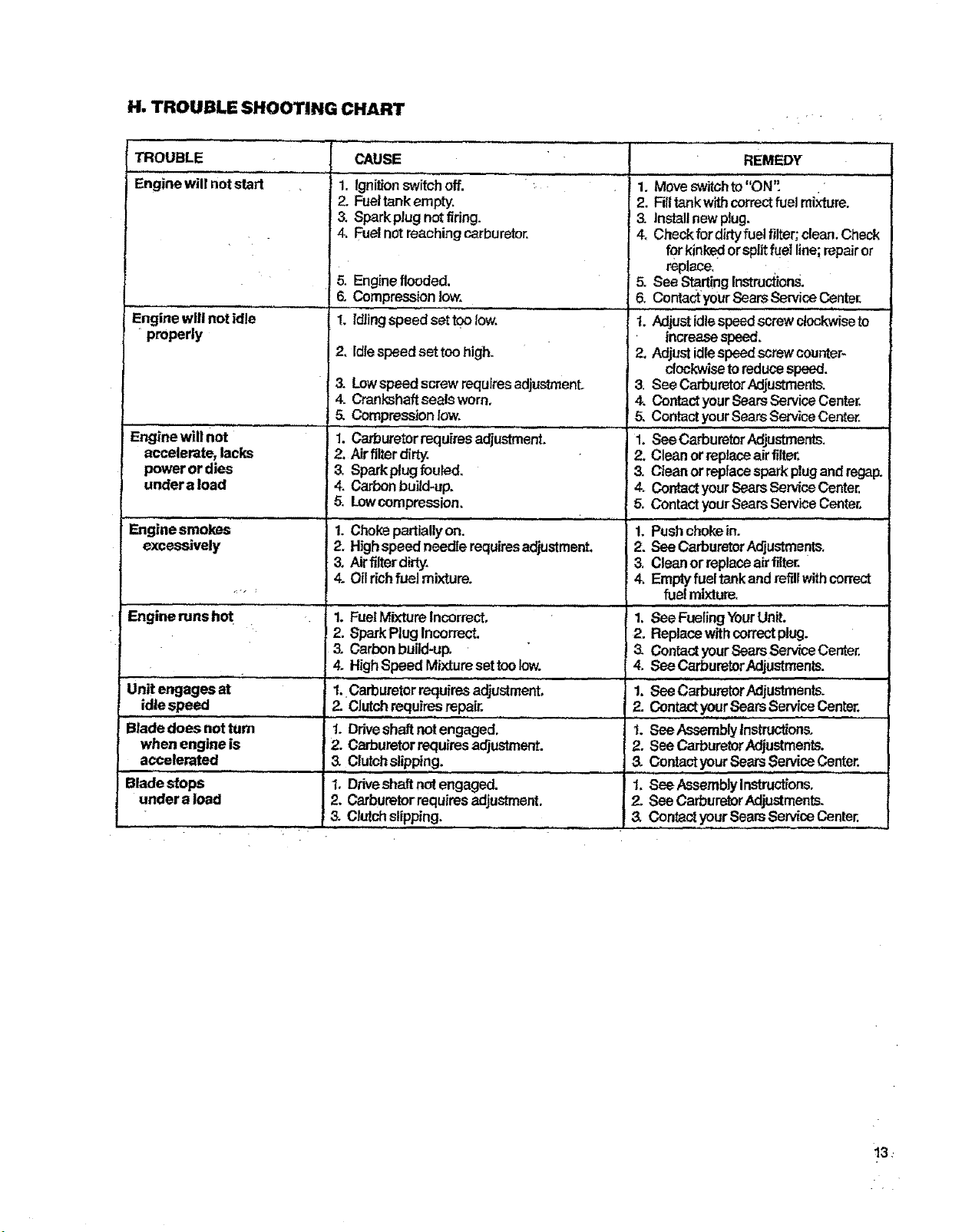
H, TROUBLE SHOOTING CHART
: r +
TROUBLE
....... ,,,,,,,
Engine will notstart
I
properly
...........11
2.
3.
CAUSE
Ignition switch off. "' _:
Fueltank empty.
Sparkplugnotfiring.
4. Fuel notreaching carburetor,
5. Engine flooded.
6. Compression low.
I. ldlingspeed settoo tow.
I2. Idlespeedset toohigh.
& Lowspeed screw requiresadjus_zenL
4. Crankshaftsealsworn.
5. Compression low.
Engine wiii not........... : 1. Carburetorrequires adjustment.
accelerate, lacks 2. Airfilterdirty.
power or dies 3. Sparkplugf_ufed.
undera load 4. Carbonbuild-up.
5. Lowcompression.
Enginesmokes ....1. ChokepartiaUyon.
excessively 2. Highspeedneedlerequiresadjustment.
3. Airfilter dirty.
4. Oil richfuel mixture.
Engine runs'hot . I. FuelMixtureIncorre'_:'" " ..........
idlespeed
,,,,,,,,.... ,,,,,
Blade does not turn
when engine is
accelerated
Blade stops
under a load
REMEDY
1. Moveswitohto "ON".
2. Filltankwithcorrectfuel mixture.
3. install newplug.
4. Chackfordirtyfuel filter; clean;Check
for kinkedorsplitfuel line;repairor
replace,
5. See StartingInstructions.
6:,Co aeyou[ arsSe ce n*e,.
1. Adjustidlespeedscrewclockwiseto
increasespeed.
2, Adjust idle speedscrewcounter-
clockwiseto reducespeed.
3. See CarburetorAdjustments.
4. ContactyourSearsService Center.
5. Contact yourSearsServiceCenter.
""i: c rbu torAdj.str.e . "
2. Cleanorreplaceairfilter,
3. Cteanor rspfacespark plugand regap.
4. Contactyour SearsServiceCenter.
5. Contact yourSearsService Center,
1. Pushchokein.
2. SeeCarburetorA_ustments.
3. Cleanorreplaceairfilter.
4. Emptyfueltankandrefillwithcorrect
fue!mixture.
1. See FuelingYourunit.
2. SparkPlug Incorrect. 2. Replacewithcorrectplug.
3. Carbonbuild-up. 3. ContactyourSearsServiceCenter.
4. HighSpeed Mixture set toolow. 4. See CarburetorAdjustments.
,L ,,,,,, .................. i ..... ,,,,,,,,,,,
1. Carburetorrequ_resa_ustment, 1. See CarburetorAdjustments.
2. Clutchrequiresrepair. 2. Contactyour SearsServlceCenter.
1. Driveshaftnotengaged, t. SeeAssembly lnstruct_ons.
2, Carburetorrequiresadjustment. 2. SeeCarburetorAdjustments.
3. Clutehslipping. 3. ContactyourSearsServiceCenter.
1, Driveshaftnotengaged. 1. See AssembJyInstructions.
2. Carburetorrequiresadjustment. 2, See CarburetorAdjustments.
3. Clutchslipp_ng. 3. ContactyourSearsServiceCenter.
13
ACCESSORIES '
The followingaccessoriesareavailablethroughSearsRetailStores,CatalogOutletsorServiceCente_
•' 2 CycleEngine.Oil ' : _ Stock No. 71 36555
Shaft _be Part No 30102
Gear Lube ...................... ' .. ,Stock No, 28-HT5S071
. -.*..o..=.._w _.******
Edger Blade R placement • " Stock No. 85731
NOTES .._. _ . _
'.,, .
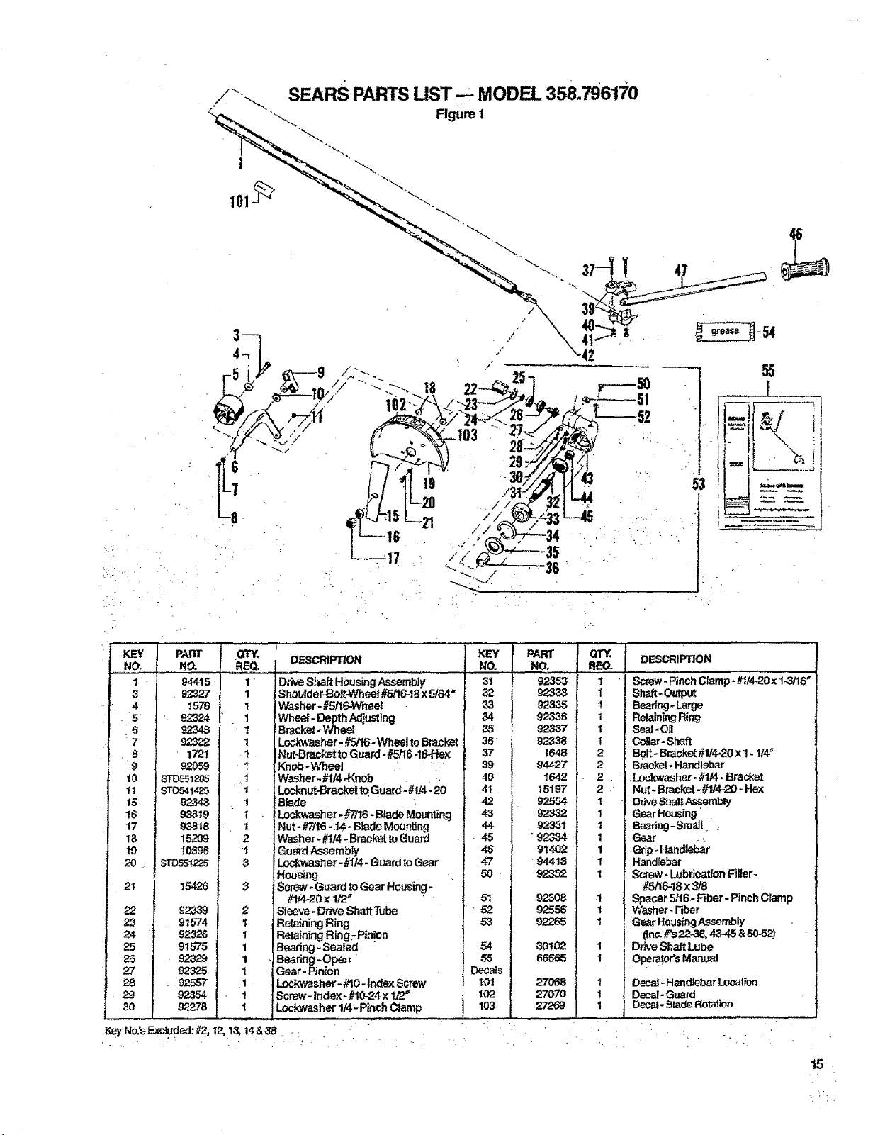
REQ.
1 94415 1
3 92327 t
5 : 92324 1
6 92348 1
7 _ 1
8 " 1721 I
9 92059 I
10 _"D551285 .1
t I STD541425 1
15 92343 1
16 93_19 1
17 97=818 1
18 15209 2
19 10396 1
20 _ ST0,551225
21 15426
22 923.39
23 91574
24 92326
25 915-'75
92329
92325
28 . 92557
29 92354
30 92278
DESCRIPTION
Drive Shaft HousLqgAssembl; ....
Shoulder-Bolt:-Wheel#5/16-18x 5/64"
Washer- #_eel
Wheel - Depth Adjusting
Bracket- WheeJ
Lockwasher - #5/16- Wheel to Bracket
Nut-Bracket to Guard - #5/16-18-Hex
Knob-Wheel
Washer - #1/4-Knob ,:
Loc_'_ut-Braokdt to Guard - #1/4_.20
Blade
ILockwasher -#'7/16-Blade Mounting
Nut - #7t16-.14 *Blade Mounting
Washer - #I/4 - Bracket toGuard
Guard AsSembly
3 Lockwasher- #//4 - Guard to Gear
Housing
3 Screw .Guard to Gear Housing-
#t/4-20 X1/2f"
2 Sleeve. Drk_eShaft Tube
I Retaining Ring
1 Retaining Ring.- Pinion
1 Bearing-Sealed "
1 Bearing -Ope_ '
1 Gear - Pin_on
1 Lockwasher - #10- Index ,Screw
1 Screw - Index-#10-24 × 1_"
t Lo_washer 1/4- Pinch Clamp
NO.
31
32
_3
34
.35
35"
37
39
40
4I
42
43
44-
• 45
46
KeyNo:s Excluded:_, 12,1& 14 & 38; .
_7
• 50 •
51
• 52
53
54
55
Decals
101
I02
103
PART QTY. DESCRIPTION
NO, RE(_
92353 I Screw- PinchClamp - #1/4-20x 1-3f16"
92333 _ Shaft - Output
92335 1 _ear;ng. Large
92336 1 RetainingRing
923,37 1 Seal - O_
92338 1 Collar- Shaft
1648 2 Bolt - Bracket#1/4-20 x 1-114_
94427 2 B_oket - Handlebar
1642 2 _Lockwasher - #1/4. Bracket
15197 2 ' NUt. Bracket - #I/4-20 - Hex
92554 1 DriveShaft Assembly
92332 1 Gear Housing ,
92_.31 1 Bearlng-Smalf :
• 92334 1 Gear r '
91402 1 Grip. HandieSt
• 94418
92352
92308
92556
92265
30102
sss_
1 Handlebar
1 Screw - Lubrioat_onFiller-
#5/16-18x 3/8
1 Spacer 5/16- F_ber- Pinch Cramp
I Washer - Rber
1 Gear HousingAsserr_ly
(ln_ #'s22-36, 43-45 & 50-52)
1 Drive Shaft Lube
1 I Operator'sManual
I rDecaJ-HandlebarLocation
1 Decal-Guard
I t Decal"B_de Ro_a_Jon
.
27O68
27070
27269
15
SEARS PARTS LIST-- MODEL 358.796170
, ,. ,, r'. r ,
t02
1-----_
12 16 ' 98
!3 15
99
/
47-
48-
54
7
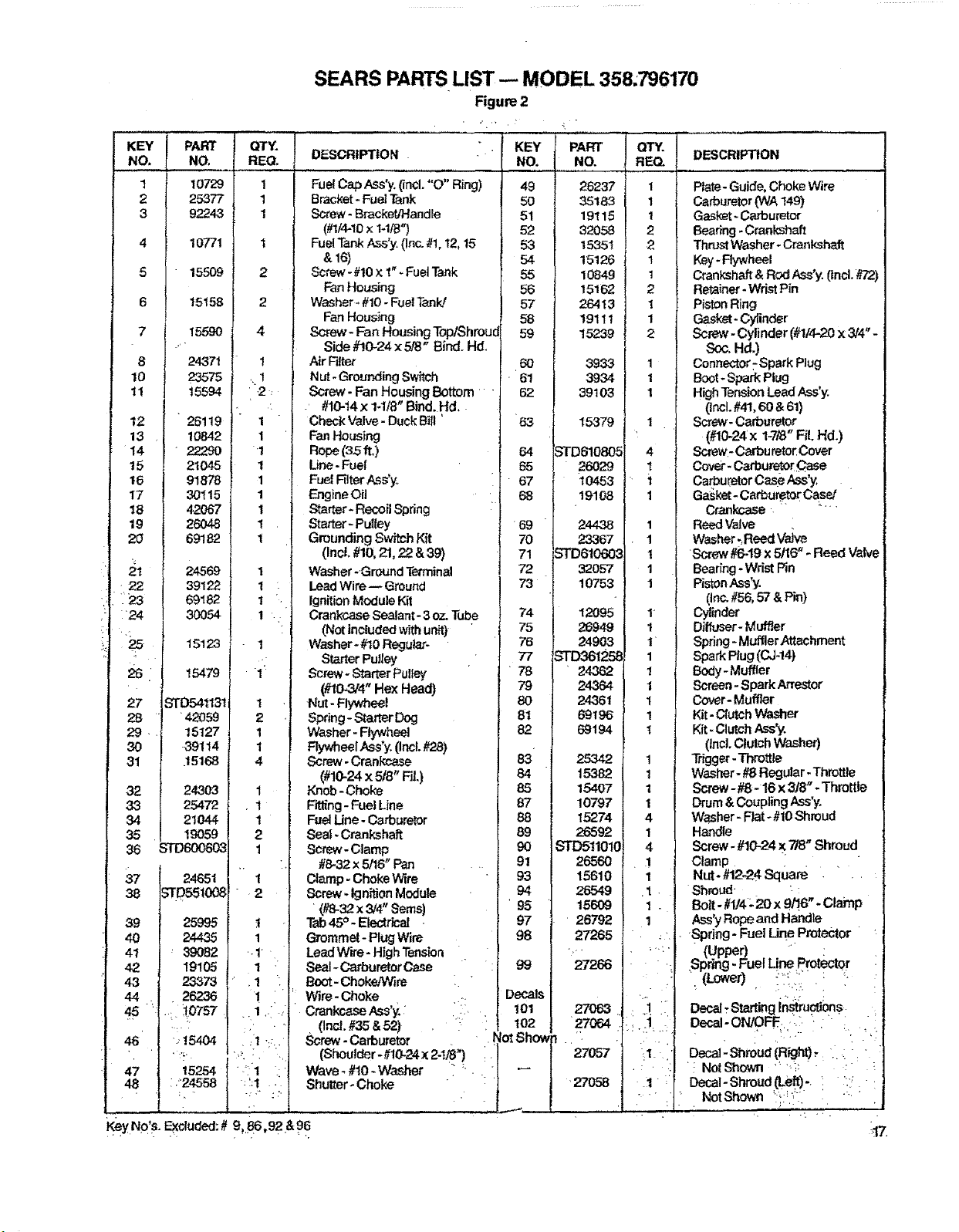
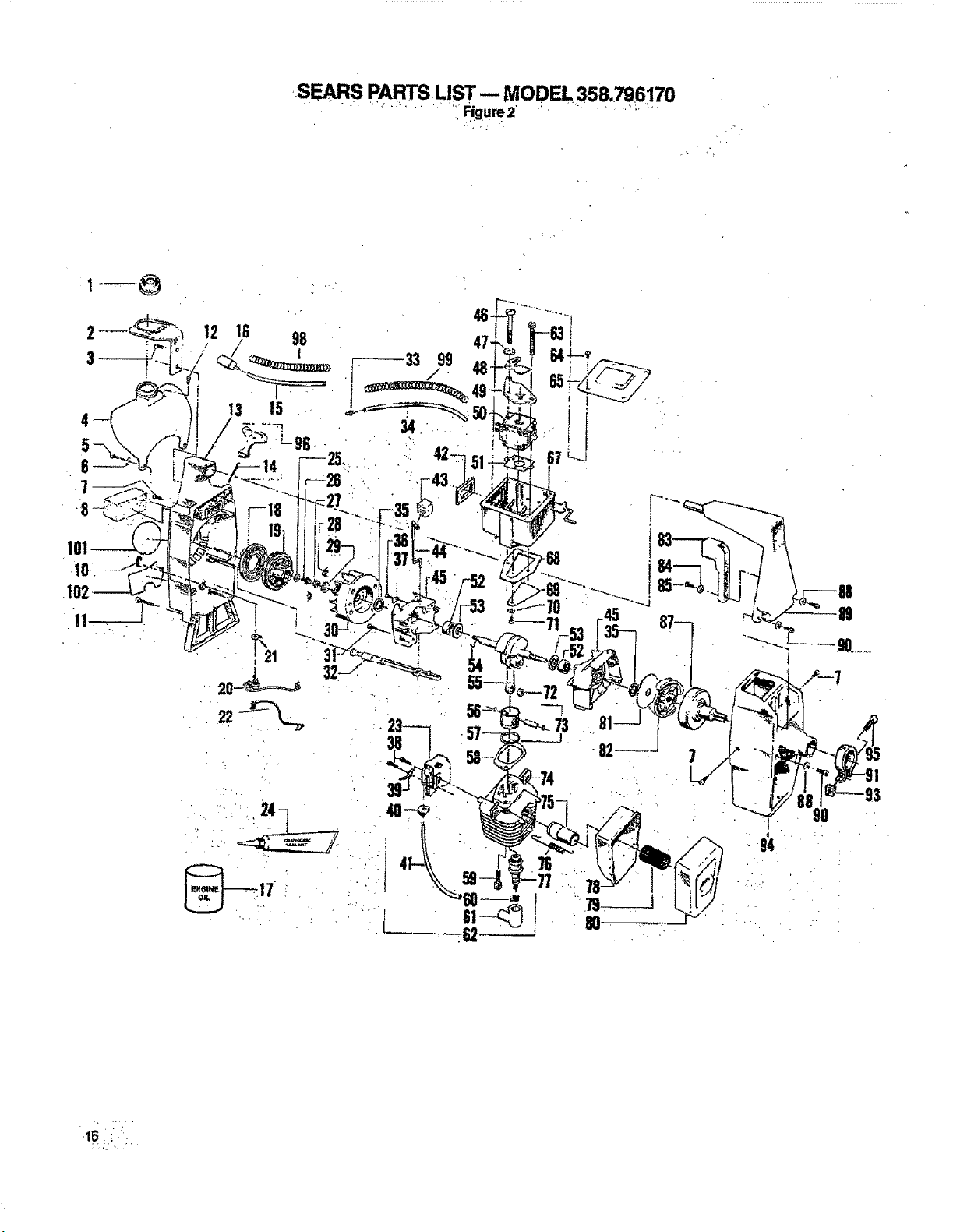
SEARS PARTS LIST- MODEL 358;796170
Figure 2
..... ,,, ,,
KE f PART
NC, NO.
t 10729
,2 25377
3 92243
4 107/1
5 15509
6 15158
7 15590
+
8 24371
10 23575
11 15594
12 26119
13 10842
14 " 22290
!5 21045
16 91878
17 30115
18 42067
19 26048
20 69182
21 24569
' 22 39122
23 69182
24 30054
lS12a
26 15479
27 5TD541131
L_ •42059
, 15127
89114
+15168
24.303
25472
21044
19O59
36 _'q'D60060_
37 24651
38
39 25995
40 24435
41 _ 39082
42 19105
43 23378
44 . 26236
"t '
46 +,15404
• :';.
47
48 : '24558
, .+
!,
REO.
1
1
1
1
2
2
4
!
2 :
• +,+ , , _ -
1
1
1
1
1
1
1
1
1
DESCRIPTION
NO.
Fuel CapAss'y+(incl. "O" Ring) 49
Bracket - FuelTank 50
8c{ew - Bracket/Handle 51
(#t/4-10x 1-1/_") 52
FuelTankAss'y. (Inc.#t, 12,15 53
&16) 54
Screw -#10 x 1"+FuelTank 55
Fan Housing 56
Washer+#10- FuelTank! 57
Fan Housing 58
Screw- Fan HousingTop/Shrou_ 59
Side #!0-24 x 518" Bind. Hd.
Air Filter 60
Nut- GroundingSwitch . 61
Screw - Fan Housing Bottom 62
- #10-14x 1-118"Bind. Hd,
PART
NO.
26237
35183
19115
32058
15351
15126
10849
15162
25413
19111
15239
3933
3934
39103
DESCRIPTION
Plate-Guide,Choke Wire
Carburetor(WA149)
Gasket- Ca,,buretor
Bearing-Crankshaft
ThrustWasher- Cranksh_lt
Key-Flywheel
Crankshaft& Rod Ass'y. (Ind. #72)
Retainer -Wr'_ Pin
Piston Ring
Gasket-Cylinder
Screw - Cylinder (#tl4-20 x 314"-
Soc. Hd.)
Connector: Spark Plug
Boot-Spark Plug
HighTensionLeadAss'y.
(incl.#41,60 & 61)
Check Valve -DuckBill '
FanHousing
Rope (35 it.)
Une -Fuel
FuelFilterAss'y.
EngineOil
Starter+Recoil Spring
Starter+Pulley
Grounding Switch Kit
(Incl.#10,21, 22 &39)
Washer-Ground Terminal
LeadWire-- Ground
Ignition Module Kit
Crankcase Seatam- 3oz.Tube
63
64
65
" 67
68
69
7O
71
72
73
15379
26O29
10453
19108
24438
23367
32057
10753
12O95
Screw-Carburetor
(#10-24x 1-7/8"Fil. Hd.)
Screw- Carbureto[ Cover
Cove'- CarburetorCase
CarburetorCase Ass'y,
Ga:_ket+CarburetorCase/ "
Crankcase.
Reed Valve
Washer_ReedValve
Screw #6-19x 5/16" - Reed Valve
Bearing-WristFin
PistonAss'y
(Inc.#56,57 &Pin)
Cylinder
1
2
1
1
4
1
.1
1
2
1
1
2
(Notincluded withunit)
Washer-#10Regular-
Starter Pulley
Screw- StarterPulley
(#10_3/4"Hex Head)
Nut -Flywheel
Spring- Starter Deg
Washer- Flywheel
FlywheelAss'y.(incl.#2a)
Screw. Crankcase
(#10-24x 5/8" Fil.)
Knob -Choke
Fitting- Fuel Line
FuelLine -Carburetor
Seal-Crankshaft
Screw- Clamp
#8-32x 5/16" Pan
Clamp-Choke Wire
Screw+Ignition Module
(#8-32x 3/4"Seres)
Tab45° - Electrical
Grommet-Plug Wire
LeadWire -HighTension
Seal+CarburetorCase
t_,oot-ChokeJWire
Wire- Choke
Crankcase Ass'y.•
. (IncL #33& 52)
,+.+/' ,
7.= _6949
7E 24903
73
7_ 24362
7_ 24.364
24361
B1 69196
B_: 69194
25342
_A 15382
E_ 15407
37 10797
15274
26592
)1 26560
_3 15610
)4 26549
_5 15609
)7 26792
)_ 27265
27266
01 27063
O2 27064
Screw-Carburetor + "
(Shoulder- #10-24x24/8") [
Wave* #t0- Washer : ; +.
Shutter- Choke " :
Key No's. Excluded:# 9 86,92 & 96
+ • ++% ., ..+ + . : ,
Diffuser-Muffler
Spring -Muffler Attachment
Spark Plug (0J-14)
Body- Muffler
Screen- SparkArrestor
Co_r- Muffler
Kit- Clutch Washer
Kit-ClutchAss'y.
(incl. ClutchWasher)
Trigger-Throttle
Washer-#8Regular. Throttle
Screw-#8-16 x 318"- Throttle
Drum & Coupling.ass'),.
W&sher- Flat+#10Shroud
Handle
Screw- #10-24x 718"Shroud
-+
Clamp .....
Nut* #12-24 Square . . ,
Shroud - :
Bolt-#1/4_20 x 9/!,6"+Clamp
Ass'y Ropeand Handle
Spring- Fuel Line Protector
S (Upper) +" :
pring -Fuel Line Protector
Decal, Startingin_ucdons
Decal-ON/OFF..+:. - " : :
Decal:Shr0ud (Right), '... " "
"i Nolghown " "'_ " " :
Decal- Shroud (Le_t)-. i ":_ ":
. NotShown "_ E!-.- . ... - •
• .,. ,, +
117.
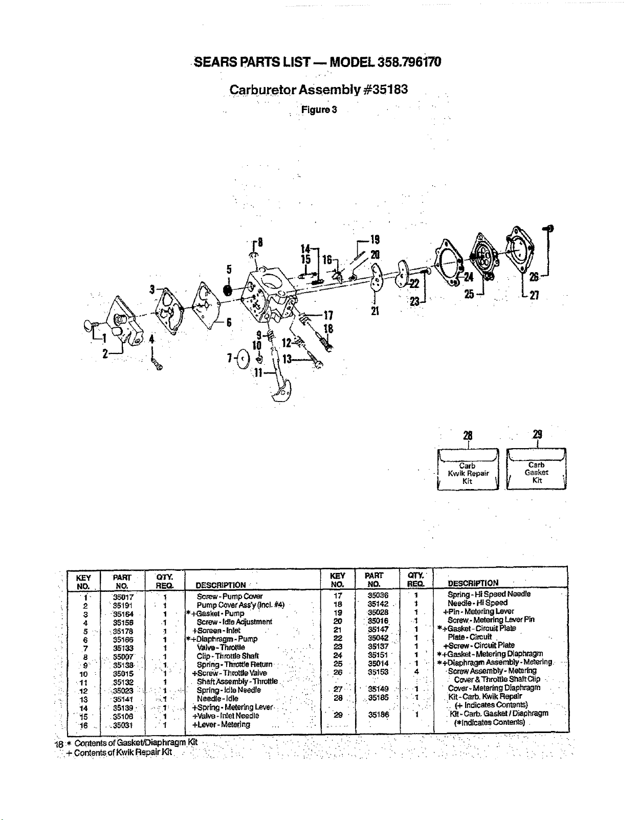
•SEARS PARTS LIST -- MODEL 358.796170
Carburetor Assembly #35183
Figure3
5
: 28 k
• - Kwik Repair / | Gasket ,_
KEY PART
NO., NO.
' 1"" 35O17 '
2 "r35191
3 " 35164
4 35158
5 '" "_35178
6 35166
7 35133
QTY.
REQ. D_-S_R1PTION " "
" ! Screw- PumpCover
! Pump CoverAss'y(incl.#4) "
1 ' _+Gasket-Pump '-
.1 Screw- Idle Adjustment
. +Semen-inlet -.
1 _=+Dlaphragm-Pump
1 Valve-ThrolU_ -... ,"_"
8 . .... 35007 . 1 Clip-,Throt_eShaft ., .
PART
NO. NO.
17 35O36
18 35142.
19 -35028
20 :13.=,01S
21 35147'
22 35042
23 35137 '_ r
24 35151 "
r_
.i i' 9" " " "35138. i :. I " 8pdng-Thr_tleRelum., _,,' -- 25 . 3_}14 - • 1 .-
10 35015 ' ' "1: : +Scrd_v-ThmttleYalve , ,': . . 26 . 35153': " 4 "
.... 11 "351_ _ . Sh_-ft_-sembly-Thlottle.: "_': :"::i.._ ":., I .... !';
.12 ":.:35023 ::_.' :' I. ',;.- Spdng-tdleNeedle L " ..: ,. i ..27 =. , 351;49 .-.... I "
1.3 -35t41 . i.:;_ =. Needle-Idle ..' ." .._ 28,: .:.051_, :_ .'1
14 -' 35139: .....,"t _. ._, :f-Sprlng-MeleringLever.. :, . 'i _| . ., '" ."
"15 " .35106 ,"1 +_Ive -Intel Needle " _ ' r " "29 35186" " " "I
-_. ":16 .... .35031 •:'f +Lever-Metering ...... ., .:......
QTY,' I¸
_= DEsc.l_r,o,
, Sp_g-HiSp_N_re
I Needle- HISpeed
I • +Pin - MeteringLever
-.1 Sc.m'_-Matedng LeverPin
1 ! _+Gaskat-Circu_t Plal_ .
1 • Plate- Cimuit. ..
I +_crew-Circuit1
Plate
1 ' /,_,+Gasket-Metering Diaphragm
*+Diaphragm Assembly-M_drlg.r --.
.ScrewAssemblyoMetering
.: Cover&Thrott;leSIl_LttClip-. .
" Cov_r-MeteringDiaphragm .
,_Kit=Carb. KwikRepOt
:. (4- IndicatesOontents) ' " -.
.'t_t- O_,arb,G_skel I Diaphragm
' (*lndlcatesOomer_).
_B * Contents ofGasketJDiaphragm t_t . " . "" "
Hll re,Hi ,,,,1 ..l= , H H ..H ,,,,,i H = ..m ,,,,,,
,.,, . ,
QUICK REFERENCE PAGE
- v
Read and follow all safety rules, precautions and operating instructions.
Failure to do so can result in serious personal injury.
_. . page
PREPARATION . .. 3
toWeareyeprotection.... ..... "
2_Dre_ssafely- boots orsafetyshoes,long pants.
3. Checkforworn, loose,missingor damaged parts and repair.
4.Inspect and makesafethe areatobe cut,
5. Keepchildren, bystanders,andanimals a minimum of30 feet(10meters)away.
:1.Eliminateall sourcesofsparksor flamewherefuelismixed, poured or stored.
2. Usegasoline notover2 monthsold.
3. UseI pad air._;ooled,2-cycleengine oilto 16parts regular unleadedgasoline : _ ; _ : _ _ ; _ : _+ _
4, Mbc'andpour fuel in anapproved,marked containerin an outdoorarea.
5. Movea minimumof 10feet (3meters)awayfromfuel endfueling site beforestartingengine.
STARTING THE ENGINE ............................................................... 7-8
1.Holdtheunit_ntheoperatingposi_onandtiltthebladetotheleft.
2.Move theignitionswitchtothe"ON" position.
3.Pullthe starterropenomorethan10timestoavoidflooding theengine.
4.Keep thethrottletriggerdepresseduntilengineruns. ..
OPERATING THE UNIT ......................... : ..... _- : "- . ............ !" •" ."':. "i":8, !0 & 1!
1.Acceleratethe engine tothe desiredspeedbefore cutting.
2. _e enginetoidle whennotcutting.
3. Stoptheengine bymoving theswitch tothe "OFF" positon.
MAINTENANCE .. 13-15
!, Disconnectsparkplugbeforeperformingmaintenance exceptfor carburetoradjustment.
2. Drainall fuelfrom theunit beforestoringfor30 daysormore.
& Lubrfcatetheflexible driveshaftafter each10hoursofoperationandafters_ringfor morethan 90 days,
4, Cleanairfilter frequentlybutalwaysafter5 hours0foperationor5 tanksoffuel,whicheverisless.
5.Store ina dryplaceoutofthereachofchildren,
IIIIIIIIII II I I III IIIIII I ......
.... ,+ -, . • . ,,
operator's
manual
MODEL NO.
358.796170 '
How to Order r
Repair Parts •
SEARS SERVICE
IS AT YOUR SERVICE
The ModelNumberwillbefound onthefanhousfngwiththeSerial Number,Always
mentiontheModelNumberwhenrequestingserviceorrepairpartsforyourunit.
Allpartslistedhereinmaybe0rderedfromanySearsServiceCenterandmostSears
Stores.
WHEN ORDERING REPAIR PARTS ALWAYS GIVE THE FOLLOWING INFORMA-
TION AS SHOWN INTHIS LtST,
3. The PART DESCRIPTION
!;'T:.hePARENUMBER . ... " .::..::: ::
2. The MODEL NUMBER 4. The NAME OF ITEM --
358.796170 22.2¢c Gas Edger
Ifthepartsyouneedarenotstockedlocally,yourorderwillbeelectronicallytransmit-
tedtoa SearsRepairPartsDistributionCenterforexpeditedhandling.
Whenyoubuymemhandlsefrom Sears
yougetanextrasomethingthatnobody
elsecanoffer.SearsServicP.
Acrosstownoracrossthecountry,Sears
. Servicefollowsyou,providingtrustworthy,
competent service technicians•using
r _ 4 " r " ' QnlySearsspecifiedfactory parts.
, , - . .',. , • : _ . ., . . :' : . • '., . ..... . ,
YourSearsMerchandisetakesonaddedvaluewhenyoudiscoverthatSearshasSer-
viceUn_mugl_utt_ counW. Each isstaffedby_ars-Tr_t, pmlessional_hni.
ciansusingSearsapprovedmethods, _
_:66665-1-01086-1-01086, ': .' - !:, : . .'_': :...... : " " " I"' '"" ' J>>"