Operator's Manual
CRRFr MRN
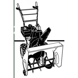
24" SNOW THROWER
Model No. 247.881721
CAUTION" Before using this
product, read this manual and
follow all safety rules and operating
instructions.
,, SAFETY
o ASSEMBLY
OPERATION
MAINTENANCE
PARTS LIST
o ESPANOL
Sears Brands Management Corporation, Hoffman Estates, IL 60179, U.S.A.
Visit our website: www.craftsman.com FormI/o 769-08175B
(June 17,2013)
WarrantyStatement.............................. Page2
SafeOperationPractices...................... Pages3-6
Assembly.................................... Pages8-11
Operation.................................. Pages12-15
Service&Maintenance...................... Pages16-22
Off-SeasonStorage............................. Page23
Troubleshooting............................... Page24
PartsList................................... Pages26-43
RepairProtectionAgreement................... Page46
Espa_ol......................................... Page47
CRAFTSMANTWOYEARFULLWARRANTY
FORTWOYEARSfromthedateof purchase,this productiswarrantedagainstanydefectsinmaterialorworkmanship.Defectiveproductwill receivefree
repairorfreereplacementif repairisunavailable.
Forwarrantycoveragedetailsto obtainrepairorreplacement,visitthewebsite:www.craftsman.com
ThiswarrantycoversONLYdefectsinmaterialandworkmanship.WarrantycoveragedoesNOTinclude:
• Expendableitemsthat canwearoutfrom normalusewithin thewarrantyperiod,includingbutnot limitedto augers,augerpaddles,driftcutters,skid
shoes,shaveplate,shearpins,sparkplug,aircleaner,belts,andoiifilter.
• Standardmaintenanceservicing,oiichanges,ortune-ups.
• Tirereplacementorrepaircausedbypuncturesfromoutsideobjects,suchasnails,thorns,stumps,orglass.
• Tireorwheelreplacementorrepairresultingfrom normalwear,accident,or improperoperationormaintenance.
• Repairsnecessarybecauseofoperatorabuse,includingbutnot limitedto damagecausedbyover-speedingtheengine,orfrom impactingobjectsthat
bendtheframe,augershaft,etc.
• Repairsnecessarybecauseofoperatornegligence,includingbutnot limitedto,electricalandmechanicaldamagecausedbyimproperstorage,failureto
usethepropergradeandamountofengineoff,orfailureto maintaintheequipmentaccordingto theinstructionscontainedinthe operator'smanual.
• Engine(fuelsystem)cleaningorrepairscausedbyfueldeterminedto becontaminatedor oxidized(stale).Ingeneral,fuelshouldbe usedwithin30days
ofitspurchasedate.
• Normaldeteriorationandwearoftheexteriorfinishes,orproductlabelreplacement.
Thiswarrantyisvoidif thisproductiseverusedwhileprovidingcommercialservicesorif rentedto anotherperson.
Thiswarrantygivesyouspecificlegalrights,andyoumayalsohaveotherrightswhichvaryfromstateto state.
SearsBrandsManagementCorporation,H0ffmanEstates,IL60179
Engine Oil: 5W-30
Fuel: Unleaded Gasoline
Engine: MTD
Model Number
Serial Number
Date of Purchase
Record the model number, serial number,
and date of purchase above.
© Sears Brands, LLC 2
Thissymbolpointsout importantsafety instructionswhich, ifnot
followed, couldendangerthe personalsafetyand/or property of
yourself and others.Readandfollow all instructions inthis manual
beforeattempting to operatethis machine.Failureto complywith these
instructionsmay resultinpersonalinjury.Whenyou seethis symbol, HEED
ITSWARNING!
CALIFORNIA PROPOSITION 65
EngineExhaust,someof its constituents,and certain vehiclecomponents
containor emit chemicalsknownto Stateof Californiato causecancerand
birth defectsorother reproductiveharm.
Thismachinewasbuilt to beoperatedaccordingto thesafeoperation
practicesinthis manual.Aswith anytype of powerequipment,
carelessnessorerror onthe part of the operatorcanresultin seriousinjury.
Thismachineiscapableof amputating fingers, hands,toesandfeet and
throwingdebris. Failureto observethefollowing safety instructionscould
resultin seriousinjuryor death.
Your Responsibility--Restrict the useof this powermachineto
personswho read,understandandfollow the warningsand instructionsin
this manualandon the machine.
SAVETHESEINSTRUCTIONS!
TRAINING
Read,understand,andfollowall instructionsonthe machineandinthe
manual(s)beforeattemptingto assembleandoperate.Failureto dosocan
resultinseriousinjury totheoperatorand/orbystanders.Keepthis manual
inasafeplaceforfutureandregularreferenceandfororderingreplacement
parts.
Befamiliarwith allcontrolsandtheir properoperation.Knowhowto stop
themachineanddisengagethemquickly.
Neverallowchildrenunder14yearsof ageto operatethis machine.Children
14andovershouldreadandunderstandtheinstructionsandsafeoperation
practicesinthis manualandonthe machineandbetrainedandsupervised
byanadult.
Neverallowadultsto operatethismachinewithout properinstruction.
Thrownobjectscancauseseriouspersonalinjury.Planyoursnow-throwing
patternto avoiddischargeof materialtowardroads,bystandersandthe like.
Keepbystanders,petsandchildrenat least75feetfrom themachinewhile it
isin operation.Stopmachineif anyoneentersthearea.
Exercisecautionto avoidslippingorfalling,especiallywhenoperatingin
reverse.
PREPARATION
Thoroughlyinspecttheareawheretheequipmentisto beused.Removeall
doormats,newspapers,sleds,boards,wiresandotherforeignobjects,which
couldbetrippedoverorthrownbytheauger/impeller.
Alwayswearsafetyglassesoreyeshieldsduringoperationandwhile
performinganadjustmentor repairto protectyoureyes.Thrownobjects
whichricochetcancauseseriousinjuryto theeyes.
Donotoperatewithout wearingadequatewinteroutergarments.Donot
wearjewelry,longscarvesorotherlooseclothing,whichcouldbecome
entangledin movingparts.Wearfootwearwhichwill improvefooting on
slipperysurfaces.
Usea groundedthree-wireextensioncordandreceptacleforall machines
with electricstartengines.
Disengageall controlleversbeforestartingtheengine.
Adjustcollectorhousingheightto cleargravelor crushedrocksurfaces.
Neverattemptto makeanyadjustmentswhileengineisrunning,except
wherespecificallyrecommendedintheoperator'smanual.
Letengineandmachineadjustto outdoortemperaturebeforestartingto
clearsnow.
Safe Handling of Gasoline:
Toavoid personalinjuryor property damageuseextreme carein handling
gasoline.Gasolineisextremely flammable andthe vaporsareexplosive.
Seriouspersonalinjurycan occurwhengasolineis spilledon yourselfor your
clotheswhichcanignite. Washyour skinandchangeclothesimmediately.
Useonlyanapprovedgasolinecontainer.
Neverfill containersinsidea vehicleorona truckortrailerbedwitha plastic
liner.Alwaysplacecontainersonthe groundawayfromyourvehiclebefore
filling.
Whenpractical,removegas-poweredequipmentfrom the truckor
trailer andrefuelit ontheground.Ifthisis not possible,thenrefuelsuch
equipmenton atrailerwith aportablecontainer,ratherthanfrom agasoline
dispensernozzle.
Keepthenozzleincontactwith the rimofthefuel tankor containeropening
at alltimesuntil fuelingiscomplete.Donot usea nozzlelock-opendevice.
Extinguishall cigarettes,cigars,pipesandothersourcesof ignition.
Neverfuel machineindoors.
Neverremovegascapor addfuelwhilethe engineishotorrunning.Allow
engineto coolat leasttwo minutesbeforerefueling.
Neveroverfill fueltank.Filltankto nomorethan1/2inchbelowbottomof
filler neckto allowspacefor fuelexpansion.
Replacegasolinecapandtightensecurely.
Ifgasolineisspilled,wipeit offthe engineandequipment.Moveunitto
anotherarea.Wait.5minutesbeforestartingtheengine.
Toreducefirehazards,keepmachinefreeofgrass,leaves,orotherdebris
build-up.Cleanupoilorfuelspillageandremoveanyfuelsoakeddebris.
Neverstorethemachineorfuelcontainerinsidewherethereisanopen
flame,sparkorpilotlightasonawaterheater,spaceheater,furnace,clothes
dryerorothergasappliances.
OPERATION
Donotput handsorfeetnearrotatingparts,intheauger/impellerhousing
orchuteassembly.Contactwith therotatingpartscanamputatehandsand
feet.
Theauger/impellercontrolleverisasafetydevice.Neverbypassits
operation.Doingsomakesthemachineunsafeandmaycausepersonal
injury.
Thecontrolleversmustoperateeasilyin bothdirectionsandautomatically
returnto thedisengagedpositionwhenreleased.
Neveroperatewith amissingor damagedchuteassembly.Keepall safety
devicesin placeandworking.
Neverrunanengineindoorsor inapoorlyventilatedarea.Engineexhaust
containscarbonmonoxide,anodorlessanddeadlygas.
Donotoperatemachinewhileundertheinfluenceof alcoholordrugs.
Mufflerandenginebecomehotandcancauseaburn.Donottouch.Keep
childrenaway.
Exerciseextremecautionwhenoperatingonorcrossinggravelsurfaces.Stay
alertforhiddenhazardsortraffic.
Exercisecautionwhenchangingdirectionandwhileoperatingonslopes.Do
notoperateon steepslopes.
Planyoursnow-throwingpatternto avoiddischargetowardswindows,
walls,carsetc.Thus,avoidingpossiblepropertydamageor personalinjury
causedbyaricochet.
Neverdirectdischargeat children,bystandersandpetsor allowanyonein
front of themachine.
Donotoverloadmachinecapacitybyattemptingto clearsnowat toofastof
arate.
Neveroperatethismachinewithoutgoodvisibilityorlight. Alwaysbesureof
yourfootingandkeepafirm holdon thehandles.Walk,neverrun.
Disengagepowerto the auger/impellerwhentransportingor not in use.
Neveroperatemachineat hightransportspeedsonslipperysurfaces.Look
downandbehindandusecarewhenbackingup.
If themachineshouldstartto vibrateabnormally,stoptheengine,
disconnectthesparkplugwire andgrounditagainsttheengine.Inspect
thoroughlyfordamage.Repairanydamagebeforestartingandoperating.
Disengageall controlleversandstopenginebeforeyouleavethe operating
position(behindthehandles).Waituntil theauger/impellercomesto
acompletestopbeforeuncloggingthe chuteassembly,makingany
adjustments,orinspections.
Neverput yourhandin thedischargeor collectoropenings.Donotunclog
chuteassemblywhileengineis running.Shutoff engineandremainbehind
handlesuntil allmovingpartshavestoppedbeforeunclogging.
Useonlyattachmentsandaccessoriesapprovedbythemanufacturer(e.g.
wheelweights,tirechains,cabsetc.).
Whenstartingengine,pull cordslowlyuntil resistanceisfelt, thenpull
rapidly.Rapidretractionofstartercord(kickback)will pullhandandarm
towardenginefasterthanyoucanletgo.Brokenbones,fractures,bruisesor
sprainscouldresult.
Ifsituationsoccurwhicharenotcoveredin thismanual,usecareandgood
judgment.
CLEARING A CLOGGED DISCHARGE CHUTE
Handcontactwith the rotatingimpellerinsidethedischargechuteisthemost
commoncauseof injuryassociatedwith snowthrowers.Neveruseyourhandto
cleanout thedischargechute.
Toclearthechute:
a. SHUTTHEENGINEOFF!
b. Wait 10secondsto besuretheimpellerbladeshavestopped
rotating.
c. Alwaysuseaclean-outtool,not yourhands.
MAINTENANCE & STORAGE
Nevertamperwith safetydevices.Checktheirproperoperationregularly.
Referto themaintenanceandadjustmentsectionsof thismanual.
Beforecleaning,repairing,orinspectingmachinedisengageall control
leversandstoptheengine.Waituntil theauger/impellercometo acomplete
stop.Disconnectthesparkplugwire andgroundagainsttheengineto
preventunintendedstarting.
Checkboltsandscrewsforpropertightnessat frequentintervalsto keepthe
machineinsafeworkingcondition.Also,visuallyinspectmachineforany
damage.
Donotchangethe enginegovernorsettingorover-speedthe engine.The
governorcontrolsthe maximumsafeoperatingspeedof theengine.
Snowthrowershaveplatesandskidshoesaresubjectto wearanddamage.
Foryoursafetyprotection,frequentlycheckallcomponentsandreplace
with originalequipmentmanufacturer's(OEM)partsonlyaslistedinthe
Partspagesofthisoperator'smanual.Useof partswhichdonot meetthe
originalequipmentspecificationsmayleadto improperperformanceand
compromisesafety!
Checkcontrolleversperiodicallyto verifytheyengageanddisengage
properlyandadjust,if necessary.Referto the adjustmentsectioninthis
operator'smanualfor instructions.
Maintainorreplacesafetyandinstructionlabels,asnecessary.
Observeproperdisposallawsandregulationsforgas,oil,etc.to protectthe
environment.
Priorto storing,runmachineafewminutesto clearsnowfrom machineand
preventfreezeupof auger/impeller.
Neverstorethe machineorfuelcontainerinsidewherethereisanopen
flame,sparkor pilot light suchasa waterheater,furnace,clothesdryeretc.
Alwaysreferto theoperator'smanualforproperinstructionsonoff-season
storage.
4
Checkfuelline,tank,cap,andfittings frequentlyfor cracksor leaks.Replace
if necessary.
Donotcrankenginewith sparkplugremoved.
Accordingto theConsumerProductsSafetyCommission(CPSC)andthe
U.S.EnvironmentalProtectionAgency(EPA),thisproducthasan Average
Useful Life of seven(7)years,or60 hoursofoperation.Attheendof
theAverage Useful Life havethemachineinspectedannuallybyan
authorizedservicedealerto ensurethat allmechanicalandsafetysystems
areworkingproperlyandnotwornexcessively.Failureto dosocanresultin
accidents,injuriesor death.
DO NOT MODIFY ENGINE
Toavoidseriousinjuryor death,do notmodifyengineinanyway. Tampering
with the governorsetting canlead to arunawayengineandcauseit to
operateat unsafespeeds.Nevertamperwith factory setting of engine
governor.
NOTICE REGARDING EMiSSiONS
Engineswhich are certifiedto complywith Californiaandfederal EPA
emissionregulationsfor SORE(SmallOff RoadEquipment)arecertified
to operateon regularunleadedgasoline,and mayincludethe following
emissioncontrolsystems:EngineModification (EM),OxidizingCatalyst(0C),
SecondaryAir injection(SAI)andThreeWayCatalyst(TWC)if soequipped.
SPARK ARRESTOR
e
Thismachineisequippedwith an internalcombustionengine andshould
not be usedon ornearany unimprovedforest-covered,brushcoveredor
grass-coveredland unlessthe engine'sexhaust systemis equippedwith a
sparkarrestormeeting applicable localor state laws (if any).
Ira sparkarrestoris used,it shouldbe maintainedin effectiveworking order
bythe operator.In theState of Californiathe aboveisrequired bylaw (Section
4442of the CaliforniaPublicResourcesCode).Otherstates mayhavesimilar
laws.Federallaws apply on federal lands.
Asparkarrestorfor the muffler is availablethroughyour nearestSearsParts
andRepairServiceCenter.
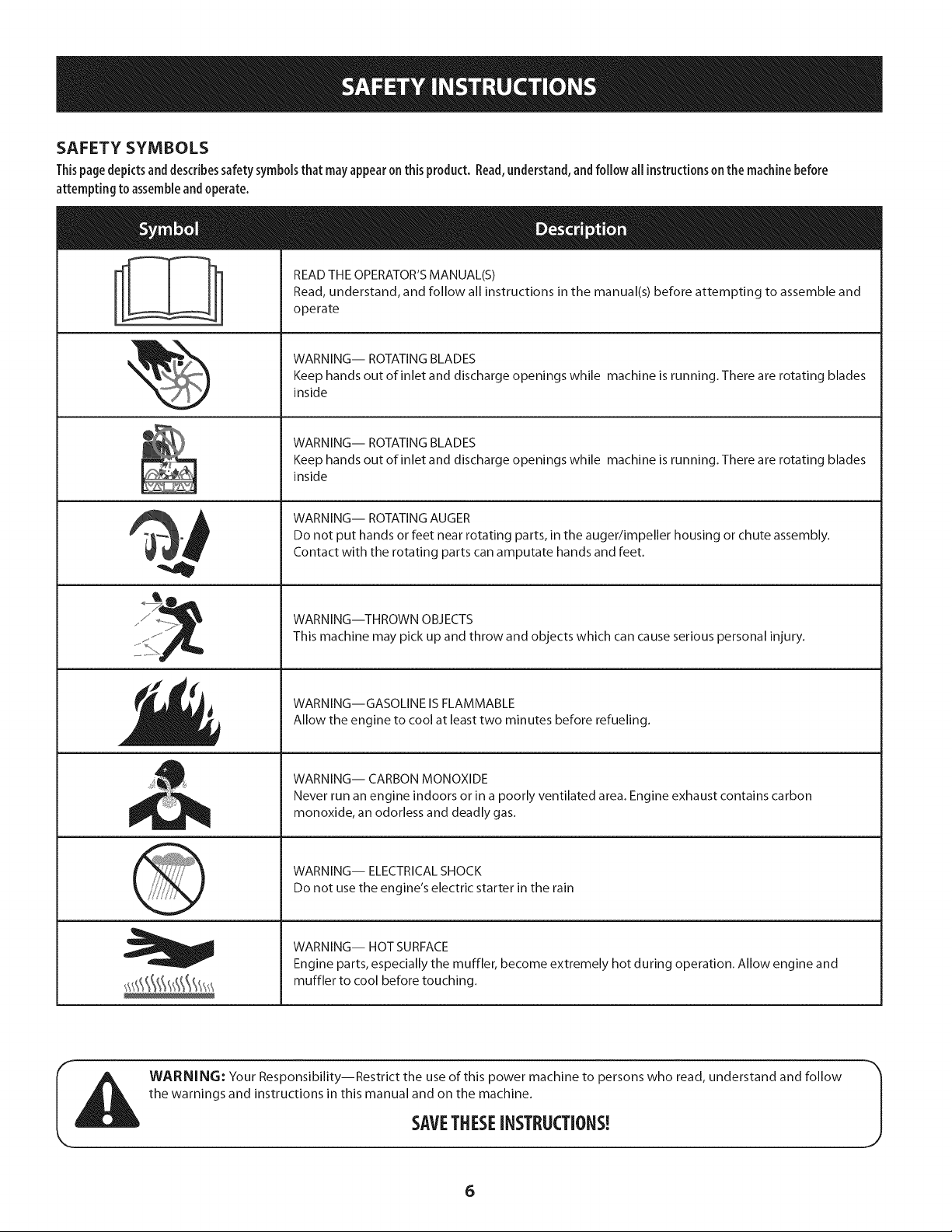
SAFETY SYMBOLS
Thispage depicts and describes safety symbols that may appear on this product. Read, understand, and follow all instructions on the machine before
attempting to assemble and operate.
READ THE OPERATOR'S MANUAL(S)
Read, understand, and follow all instructions in the manual(s) before attempting to assemble and
operate
WARNING-- ROTATING BLADES
Keep hands out of inlet and discharge openings while machine is running. There are rotating blades
inside
WARNING-- ROTATING BLADES
Keep hands out of inlet and discharge openings while machine is running. There are rotating blades
inside
WARNING-- ROTATING AUGER
Do not put hands or feet near rotating parts, in the auger/impeller housing or chute assembly.
Contact with the rotating parts can amputate hands and feet.
WARNING--THROWN OBJECTS
This machine may pick up and throw and objects which can cause serious personal injury.
WARNING--GASOLINE IS FLAMMABLE
Allow the engine to cool at least two minutes before refueling.
WARNING-- CARBON MONOXIDE
Never run an engine indoors or in a poorly ventilated area. Engine exhaust contains carbon
monoxide, an odorless and deadly gas.
WARNING-- ELECTRICAL SHOCK
Do not use the engine's electric starter in the rain
WARNING-- HOT SURFACE
Engine parts, especially the muffler, become extremely hot during operation. Allow engine and
muffler to cool before touching.
WARNING: Your Responsibility--Restrict the use of this power machine to persons who read, understand and follow
the warnings and instructions in this manual and on the machine.
SAVETHESEiNSTRUCTIONS!
6

This page left intentionallyblank.
7
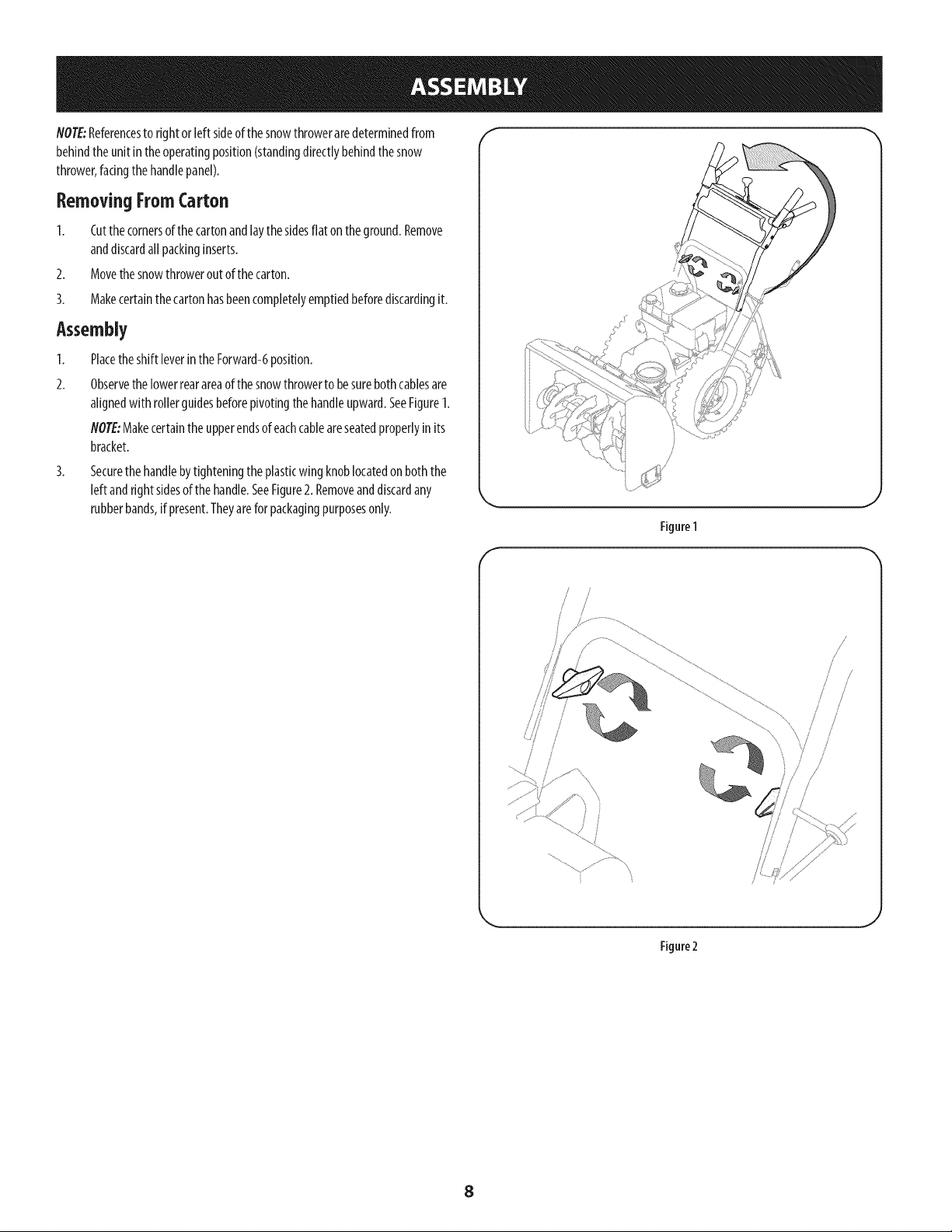
NOTE:Referencesto rightor left sideofthesnowthroweraredeterminedfrom
behindthe unit in theoperatingposition(standingdirectlybehindthesnow
thrower,facingthehandlepanel).
Removing FromCarton
1. Cutthe cornersof thecartonandlaythesidesflat on theground.Remove
anddiscardallpackinginserts.
2. Movethesnowthroweroutof thecarton.
3. Makecertainthecartonhasbeencompletelyemptiedbeforediscardingit.
Assembly
1. Placetheshift leverintheForward-6position.
2. Observethe lowerrearareaof thesnowthrowerto besurebothcablesare
alignedwith rollerguidesbeforepivotingthehandleupward.SeeFigure1.
NOTE:Makecertainthe upperendsof eachcableareseatedproperlyin its
bracket.
3. Securethehandlebytighteningtheplasticwingknoblocatedonboththe
left andrightsidesof the handle.SeeFigure2. Removeanddiscardany
rubberbands,if present.Theyarefor packagingpurposesonly.
f
k.
Figure 1
/
/
/
/
\
Figure2
8
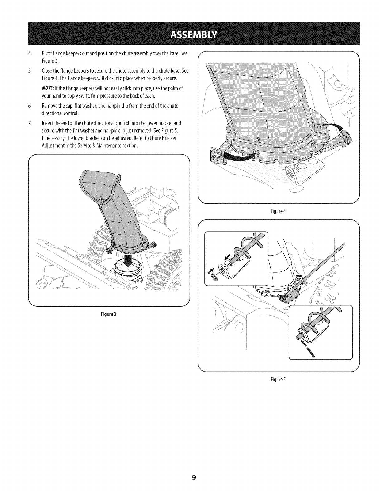
4. Pivotflangekeepersoutandpositionthechuteassemblyoverthe base.See
Figure3.
5. Closetheflangekeeperstosecurethechuteassemblyto thechutebase.See
Figure4.Theflangekeeperswill clickintoplacewhenproperlysecure.
NOTE:Iftheflangekeeperswill noteasilyclickintoplace,usethe palmof
yourhandto applyswift,firm pressureto thebackof each.
6. Removethecap,flat washer,andhairpinclipfrom the endof thechute
directionalcontrol.
Insertthe endofthechutedirectionalcontrolintothe lowerbracketand
securewith theflat washerandhairpinclipjust removed.SeeFigure5.
If necessary,thelowerbracketcanbeadjusted.Referto ChuteBracket
AdjustmentintheService& Maintenancesection.
f
Figure4
f
Figure3
J
Figure5
9

Set-Up f
ChuteClean-OutTool
Achuteclean-outtoolisfastenedto thetopoftheaugerhousingwith amounting
clip.SeeFigure6.Thetool isdesignedto cleara chuteassemblyof iceandsnow.
Thisitem isfastenedwitha cabletieat thefactory.Cutthecabletie before
operatingthesnowthrower.
Neveruseyour handsto clearaclogged chuteassembly.Shutoff engine
and remainbehind handlesuntil all movingparts havestoppedbefore
usingthe clean-outtool to clearthe chuteassembly.
TirePressure
Underany circumstancedo notexceedmanufacturer'srecommendedpsi.
Equaltire pressureshouldbe maintainedat all times. Excessivepressure
when seatingbeadsmaycausetireldm assemblyto burstwith force
sufficient to causeseriousinjury. Referto sidewall of tire for recommended
pressure.
Thetiresareover-inflatedforshippingpurposes.Checkthe tire pressurebefore
operatingthesnowthrower.Refertothetiresidewall for tiremanufacturer's
recommendedpsianddeflate(orinflate)thetiresasnecessary.
NOTE:Equaltire pressureisto bemaintainedat alltimesforperformancepurposes.
Adjustments
Skid Shoes
Thesnowthrowerskidshoesareadjustedupwardatthefactoryforshipping
purposes.Adjustthemdownward,ifdesired,priortooperatingthesnowthrower.
It is notrecommendedthat you operate this snowthrower on gravelas
it caneasilypickup andthrow loosegravel,causingpersonalinjury or
damageto the snowthrower andsurroundingproperty.
Forclosesnowremovalon asmoothsurface,raiseskidshoeshigheronthe
augerhousing.Referto Figure7.
Useamiddleorlowerpositionwhenthe areato beclearedisuneven,suchas
agraveldriveway.
NOTE:Ifyouchooseto operatethesnowthroweronagravelsurface,keep
theskidshoesinpositionformaximumclearancebetweenthegroundand
theshaveplate.
Toadjusttheskidshoes:
1. Loosenthe four hexnuts (twooneachside)andcarriagebolts.Moveskid
shoesto desiredposition.SeeFigure7.
2. Makecertaintheentirebottomsurfaceof skidshoeisagainstthe groundto
avoidunevenwearon the skidshoes.
ChuteClean-out Tool
Figure6
Smooth Surface
UnevenSurface
Figure7
3. Retightennutsandboltssecurely.
10
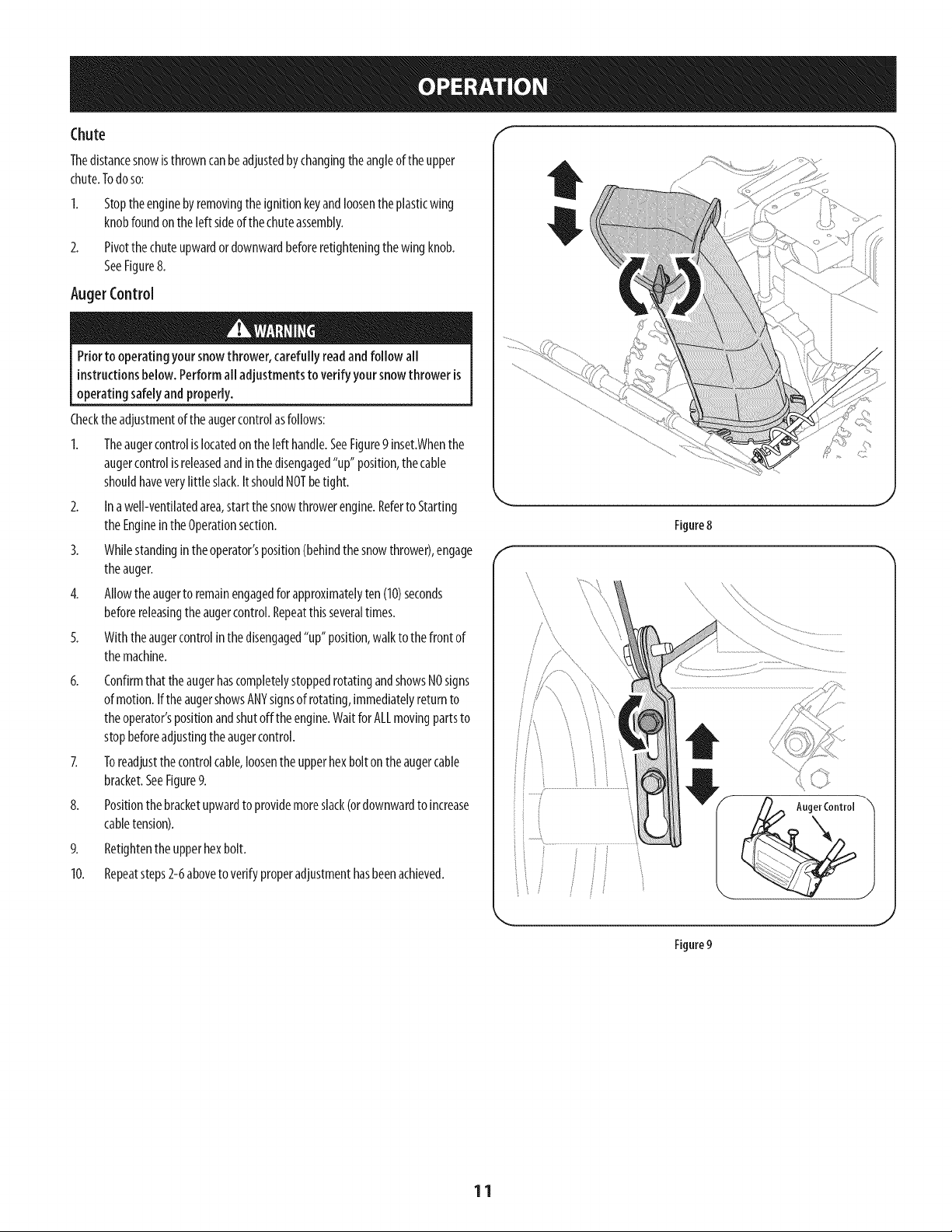
Chute f %
Thedistancesnowisthrowncanbeadjustedbychangingtheangleoftheupper
chute.Todoso:
2_
Stoptheenginebyremovingthe ignitionkeyandloosenthe plasticwing
knobfoundonthe left sideofthe chuteassembly.
Pivotthe chuteupwardordownwardbeforeretighteningthewingknob.
SeeFigure8.
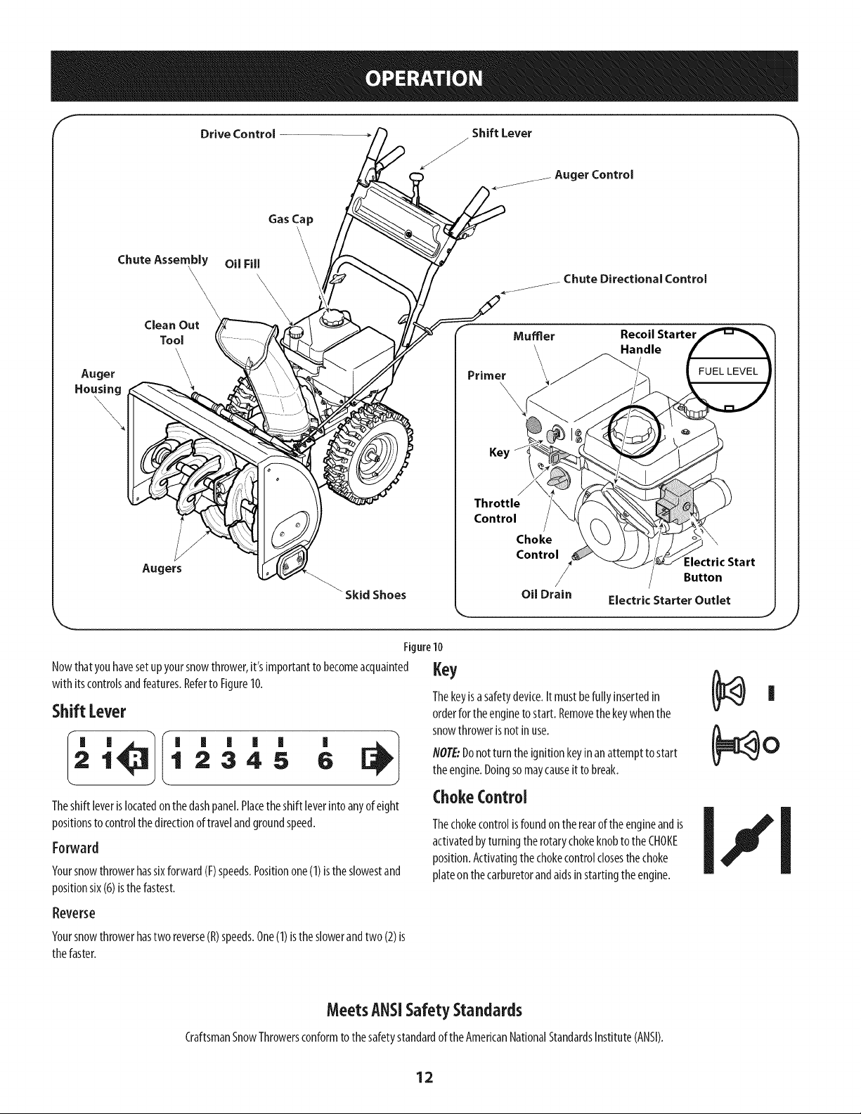
AugerControl
Priorto operatingyoursnowthrower, carefully readand follow all
instructionsbelow. Performall adjustmentsto verifyyoursnowthrower is
operating safelyand properly.
Checktheadjustmentoftheaugercontrolasfollows:
1. Theaugercontrolislocatedonthe left handle.SeeFigure9inset.Whenthe
augercontrolisreleasedandinthe disengaged"up" position,the cable
shouldhaveverylittle slack.ItshouldNOTbetight.
2. Ina well-ventilatedarea,start thesnowthrowerengine.Referto Starting
theEngineintheOperationsection.
3. Whilestandinginthe operator'sposition(behindthesnowthrower),engage
theauger.
4. Allowtheaugerto remainengagedfor approximatelyten(10)seconds
beforereleasingtheaugercontrol.Repeatthisseveraltimes.
5. With theaugercontrolin thedisengaged"up" position,walkto thefront of
themachine.
6. Confirmthat theaugerhascompletelystoppedrotatingandshowsNOsigns
of motion.Ifthe augershowsANYsignsof rotating,immediatelyreturnto
theoperator'spositionandshut off the engine.WaitforALLmovingpartsto
stopbeforeadjustingthe augercontrol.
7. Toreadjustthecontrolcable,loosenthe upperhexbolt onthe augercable
bracket.SeeFigure9.
8. Positionthebracketupwardto providemoreslack(ordownwardto increase
cabletension).
9. Retightenthe upperhexbolt.
10. Repeatsteps2-6aboveto verifyproperadjustmenthasbeenachieved.
f
Figure 8
\\
..........
J
J
Figure9
11
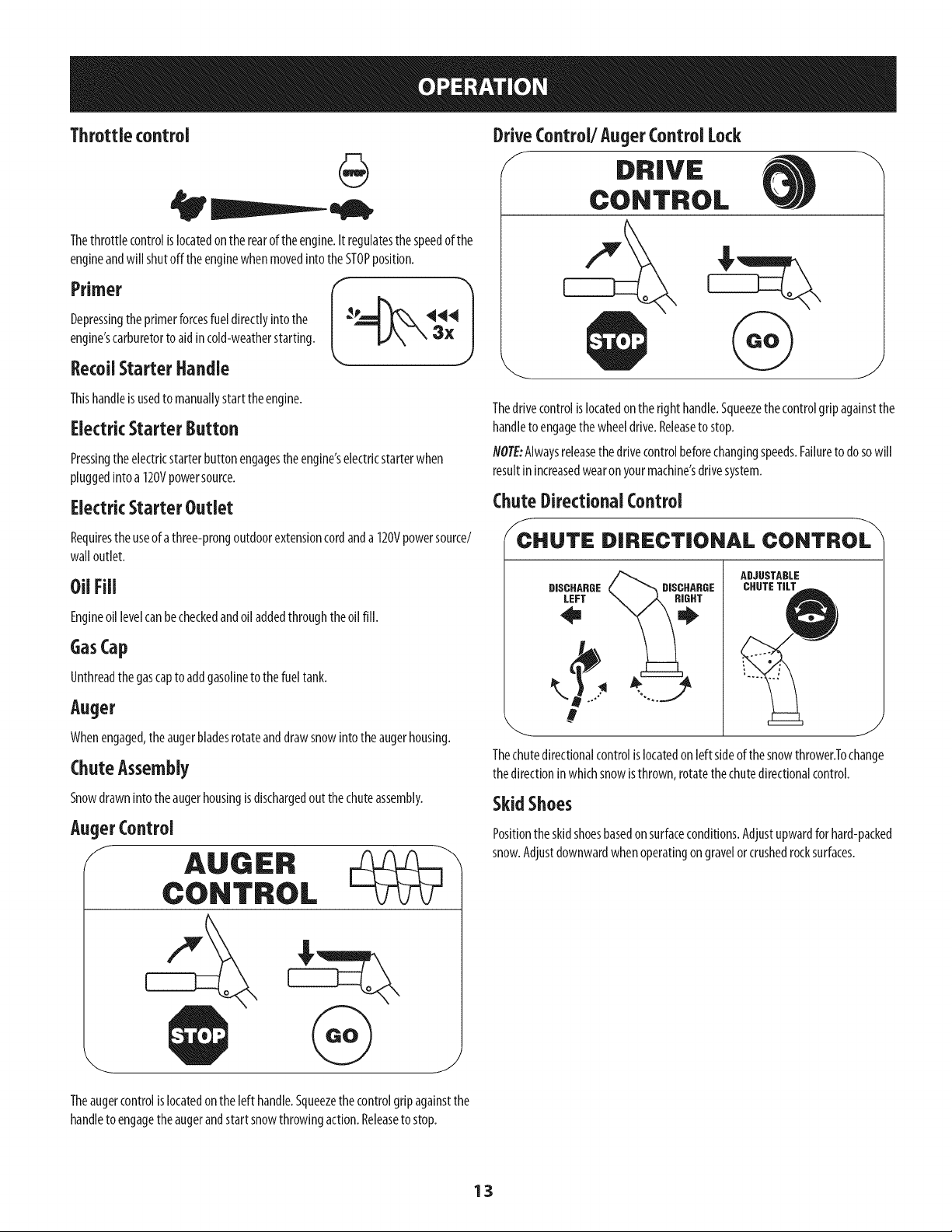
Drive Control
Shift Lever
J
Auger Control
Gas Cap
\
Chute Assembly
\,
Clean Out
Tool
Auger
Housing
\
Augers
Oil Fill
\\\\
\\
\
Muffler Recoil Starter
ndle
\
\
Key
Skid Shoes
Figure10
Nowthatyouhavesetupyoursnowthrower,it'simportantto becomeacquainted
with itscontrolsandfeatures.Referto Figure10.
Shift Lever
I_ '_1 ' ' ' ' ' '
1 2345 6
Theshift leverislocatedonthe dashpanel.Placethe shiftleverintoanyofeight
positionsto controlthedirectionof travelandgroundspeed.
Forward
Yoursnowthrowerhassixforward(F)speeds.Positionone(1)isthe slowestand
positionsix(6)isthe fastest.
Key
Thekeyisasafetydevice.It mustbefully insertedin
orderfor theenginetostart. Removethekeywhenthe
snowthrowerisnotin use.
NOTE:Donot turn theignitionkeyinan attemptto start
theengine.Doingsomaycauseit to break.
ChokeControl
Thechokecontrolisfoundontherearoftheengineandis
activatedbyturningthe rotarychokeknobto theCHOKE
position.Activatingthechokecontrolclosesthe choke
plateon thecarburetorandaidsinstartingtheengine.
Reverse
Yoursnowthrowerhastworeverse(R)speeds.One(1)istheslowerandtwo(2)is
thefaster.
MeetsANSiSafetyStandards
CraftsmanSnowThrowersconformto thesafetystandardof theAmericanNationalStandardsInstitute(ANSI).
12
Throttlecontrol
Thethrottlecontrolislocatedonthe rearofthe engine.It regulatesthe speedofthe
engineandwill shutoffthe enginewhenmovedinto theSTOPposition.
Depressingthe primerforcesfueldirectlyintothe _e 444
engine'scarburetorto aid incold-weatherstarting. 3X
RecoilStarter Handle
Thishandleisusedto manuallystartthe engine.
Electric Starter Button
Pressingthe electricstarterbuttonengagesthe engine'selectricstarterwhen
pluggedinto a 120Vpowersource.
Electric Starter Outlet
Requirestheuseof athree-prongoutdoorextensioncordanda 120Vpowersource/
wall outlet.
OUFill
Engineoil levelcanbecheckedandoil addedthroughtheoil fill.
GasCap
Unthreadthe gascapto addgasolinetothefuel tank.
Auger
Whenengaged,theaugerbladesrotateanddrawsnowintotheaugerhousing.
ChuteAssembly
Snowdrawninto theaugerhousingisdischargedout thechuteassembly.
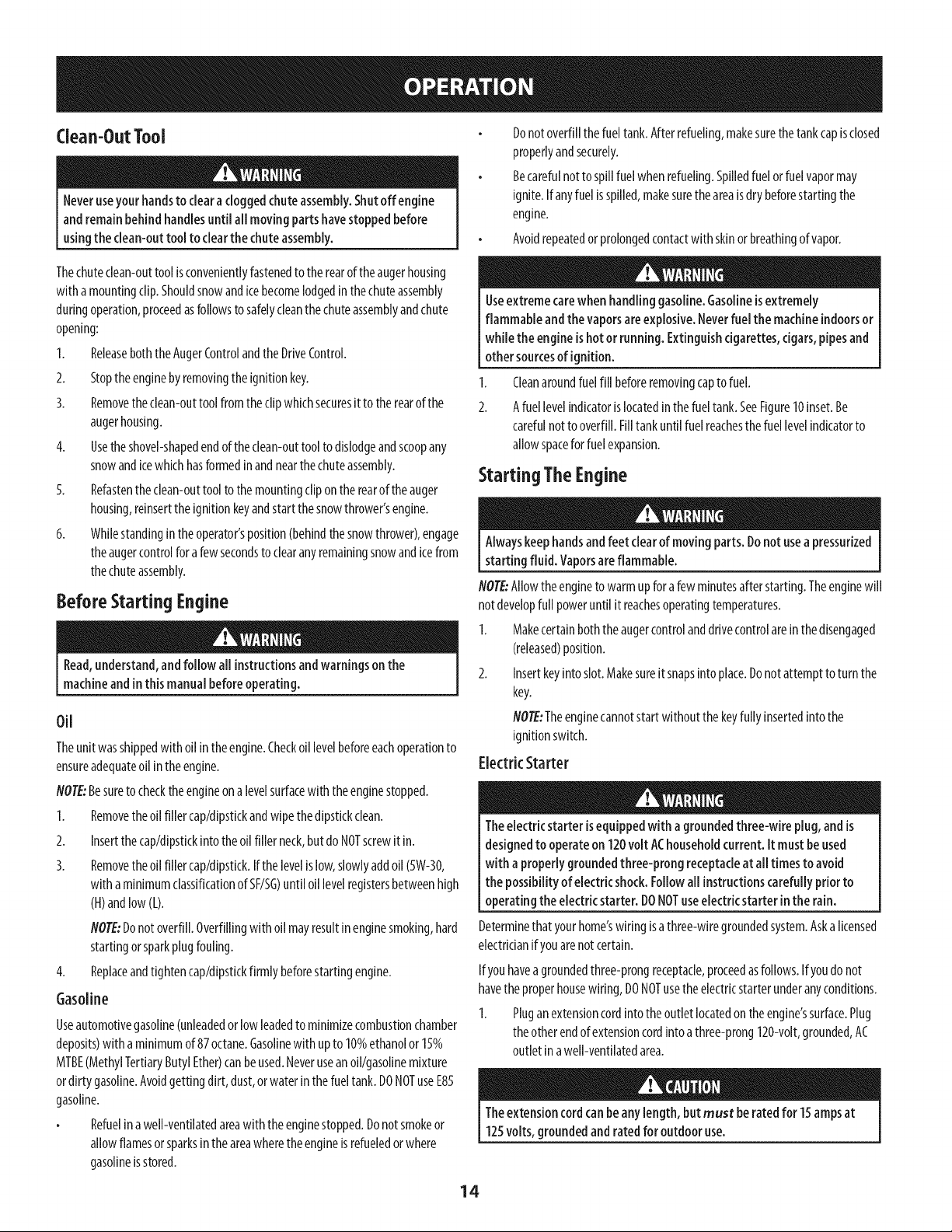
AugerControl
f
AUGER
CONTROL
DriveControl/Auger Control Lock
f DRIVE
CONTROL
Thedrivecontrolislocatedontheright handle.Squeezethe controlgripagainstthe
handleto engagethe wheeldrive.Releaseto stop.
NOTE:Alwaysreleasethedrivecontrolbeforechangingspeeds.Failureto dosowill
resultinincreasedwearon yourmachine'sdrivesystem.
ChuteDirectional Control
f
CHUTE DIRECTIONAL CONTROL
DISCHARGE
LEFT
ADJUSTABLE
CHUTETILT
Thechutedirectionalcontrolislocatedon left sideof thesnowthrower.Tochange
thedirectioninwhichsnowisthrown,rotatethechutedirectionalcontrol.
SkidShoes
Positionthe skidshoesbasedonsurfaceconditions.Adjustupwardforhard-packed
snow.Adjustdownwardwhenoperatingon gravelorcrushedrocksurfaces.
Theaugercontrolislocatedon the left handle.Squeezethe controlgripagainstthe
handleto engagetheaugerandstartsnowthrowingaction.Releaseto stop.
13
Clean-OutTool
Neveruseyour handsto clearacloggedchuteassembly.Shutoff engine
and remainbehindhandlesuntil all movingparts havestoppedbefore
usingthe clean-outtool to clearthe chuteassembly.
Thechutedean-outtool isconvenientlyfastenedto therearoftheaugerhousing
with amountingclip.Shouldsnowandicebecomelodgedin thechuteassembly
duringoperation,proceedasfollowsto safelycleanthe chuteassemblyandchute
opening:
1. ReleaseboththeAugerControlandthe DriveControl.
2. Stopthe enginebyremovingthe ignitionkey.
3. Removetheclean-outtoolfrom the clipwhichsecuresit to therearof the
augerhousing.
4. Usetheshovel-shapedendof theclean-outtoolto dislodgeandscoopany
snowandicewhichhasformedinandnearthechuteassembly.
5. Refastenthe clean-outtool to themountingdip on the rearof theauger
housing,reinserttheignitionkeyandstartthe snowthrower'sengine.
6. Whilestandinginthe operator'sposition(behindthesnowthrower),engage
theaugercontrolforafewsecondstoclearanyremainingsnowandicefrom
thechuteassembly.
BeforeStarting Engine
Read,understand,andfollow all instructionsandwarnings onthe
machineandinthis manualbeforeoperating.
Oil
Theunit wasshippedwith oilin theengine.Checkoil levelbeforeeachoperationto
ensureadequateoil in theengine.
flO?E:Besureto checkthe engineonalevelsurfacewith theenginestopped.
1. Removetheoil filler cap/dipstickandwipethe dipstickclean.
2. Insertthe cap/dipstickinto theoil filler neck,but do NOTscrewit in.
3. Removetheoil filler cap/dipstick.Ifthe levelislow,slowlyaddoil (5W-30,
with aminimumclassificationof SF/SG)until oil levelregistersbetweenhigh
(H)andlow (L).
4.
flOTE:Donot overfill.Overfillingwith oilmayresultin enginesmoking,hard
startingorsparkplug fouling.
Replaceandtighten cap/dipstickfirmlybeforestartingengine.
Gasoline
Useautomotivegasoline(unleadedorlow leadedto minimizecombustionchamber
deposits)with a minimumof87 octane.Gasolinewith upto 10%ethanolor15%
MTBE(MethylTertiaryButylEther)canbeused.Neveruseanoil/gasolinemixture
ordirty gasoline.Avoidgetting dirt, dust,orwaterinthefuel tank.DONOTuseE85
gasoline.
Refuelin awell-ventilatedareawith theenginestopped.Donotsmokeor
allowflamesor sparksin theareawheretheengineisrefueledorwhere
gasolineisstored.
Donotoverfill thefueltank.Afterrefueling,makesurethe tankcapisclosed
properlyandsecurely.
Becarefulnot to spillfuelwhenrefueling.Spilledfuel orfuel vapormay
ignite.If anyfuelisspilled,makesuretheareaisdry beforestartingthe
engine.
Avoidrepeatedor prolongedcontactwith skinorbreathingofvapor.
Useextreme carewhen handling gasoline.Gasolineis extremely
flammable andthe vaporsareexplosive.Neverfuel the machineindoorsor
while the engine ishotor running. Extinguishcigarettes,cigars,pipes and
othersourcesof ignition.
1.
2.
Cleanaroundfuelfill beforeremovingcapto fuel.
Afuel levelindicatoris locatedinthe fuel tank.SeeFigure10inset.Be
carefulnotto overfill.Filltankuntil fuel reachesthefuellevelindicatorto
allowspacefor fuelexpansion.
Starting The Engine
Alwayskeephandsandfeet clearof moving parts. Donot usea pressurized
starting fluid. Vaporsareflammable.
flOTE:Allowthe engineto warmupfor afewminutesafter starting.Theenginewill
notdevelopfull poweruntil it reachesoperatingtemperatures.
1. Makecertainboththeaugercontrolanddrivecontrolarein thedisengaged
(released)position.
2. Insertkeyintoslot.Makesureit snapsinto place.Donotattemptto turn the
key.
NOTE:Theenginecannotstartwithoutthe keyfully insertedinto the
ignitionswitch.
ElectricStarter
Theelectric starter isequippedwith a groundedthree-wire plug, and is
designedto operateon 120volt AChouseholdcurrent.It mustbe used
with a properlygroundedthree-prong receptacleat all times to avoid
the possibilityof electricshock.Followall instructionscarefully priorto
operatingthe electricstarter. DONOTuseelectric starter inthe rain.
Determinethatyourhome'swring isathree-wiregroundedsystem.Aska licensed
electricianif youarenotcertain.
Ifyouhavea groundedthree-prongreceptacle,proceedasfollows.If youdonot
havethe properhousewiring,DONOTusetheelectricstarterunderanyconditions.
1. Pluganextensioncordinto theoutletlocatedon theengine'ssurface.Plug
theotherendofextensioncordintoathree-prong120-volt,grounded,AC
outlet inawell-ventilatedarea.
Theextensioncordcan beanylength, but must beratedfor 15ampsat
125volts,groundedand ratedfor outdoor use.
14
2. Movethrottle controlto FAST(rabbit)_Jl__ position.
3 MovechoketotheCHOKEI,'I pos t on co,deng nestart),fengine s
warm,placechokein RUNposition.
4. Pushprimerthree(3)times,makingsureto covervent holeinprimerbulb
whenpushing.Ifengineiswarm,pushprimeronlyonce.Alwayscovervent
holewhenpushing.Coolweathermayrequireprimingto berepeated.
5. Pushstarterbuttonto startengine.Oncetheenginestarts,immediately
releasestarterbutton.Electricstarterisequippedwith thermaloverload
protection;systemwill temporarilyshut-downto allowstarterto coolif
electricstarterbecomesoverloaded.
6.
Asthe enginewarms,slowlyrotatethechokecontrolto RUNposition.Ifthe
enginefalters,restartengineandrunwith chokeat half-chokepositionfor a
shortperiodof time,andthenslowlyrotatethechokeinto RUNposition.
Afterengineisrunning,disconnectpowercordfrom electricstarter.When
disconnecting,alwaysunplugthe endat thewall outletbeforeunplugging
theoppositeendfromthe engine.
RecoilStarter
Donot pull the starter handlewhilethe enginerunning.
1. Movethrottle controlto FAST(rabbit)_ _j position.
2. Movechoketo theCHOKEI,.1position(coldenginestart).If engineis
warm,placechokein RUNposition.
3. Pushprimerthree(3)times,makingsureto covervent holewhenpushing.
If engineiswarm,pushprimeronlyonce.Alwayscoverventholewhen
pushing.Coolweathermayrequireprimingto be repeated.
4. Pullgentlyonthestarterhandleuntil it beginsto resist,then pullquickly
andforcefullyto overcomethe compression.Donotreleasethe handleand
allowit to snapback.ReturnropeSLOWLYto originalposition.If required,
repeatthisstep.
5. Astheenginewarms,slowlyrotatethe chokecontrolto RUNposition.Ifthe
enginefalters,restartengineandrunwith chokeat half-chokepositionfor a
shortperiodof time,andthenslowlyrotatethechokeinto RUNposition.
Toavoid unsupervisedengineoperation, neverleavethe machine
unattendedwith theengine running. Turnthe engineoff after useand
removekey.
Stopping TheEngine
Afteryouhavefinishedsnow-throwing,runenginefor afewminutesbefore
stoppingto helpdry offany moistureon theengine.
1. Movethrottle controlto OFFposition.
2. Removethekey.Removingthe keywill reducethepossibilityof
unauthorizedstartingof the enginewhileequipmentisnot inuse.Keepthe
keyina safeplace.Theenginecannotstartwithout thekey.
3. Wipeanymoistureawayfromthecontrolson the engine.
ToEngageDrive
1. With thethrottlecontrolinthe Fast(rabbit)_ _1 position,moveshift lever
into oneof thesixforward(F)positionsortwo reverse(R)positions.Selecta
speedappropriatefor thesnowconditionsanda paceyou'recomfortable
with.
flOTE:Whenselectinga DriveSpeed,usetheslowerspeedsuntilyouare
comfortableandfamiliarwith theoperationof thesnowthrower.
2. Squeezethe drivecontrolagainstthehandleandthe snowthrowerwill
move.Releaseit anddrivemotionwill stop.
NOTE:NEVERrepositiontheshift lever(changespeedsordirectionof travel)
without first releasingthedrivecontrolandbringingthesnowthrowerto a
completestop.Doingsowill resultin prematurewearto thesnowthrower'sdrive
system.
ToEngageAuger
Toengagetheaugerandstartthrowingsnow,squeezetheaugercontrol
againstthe left handle.Releaseto stoptheauger.
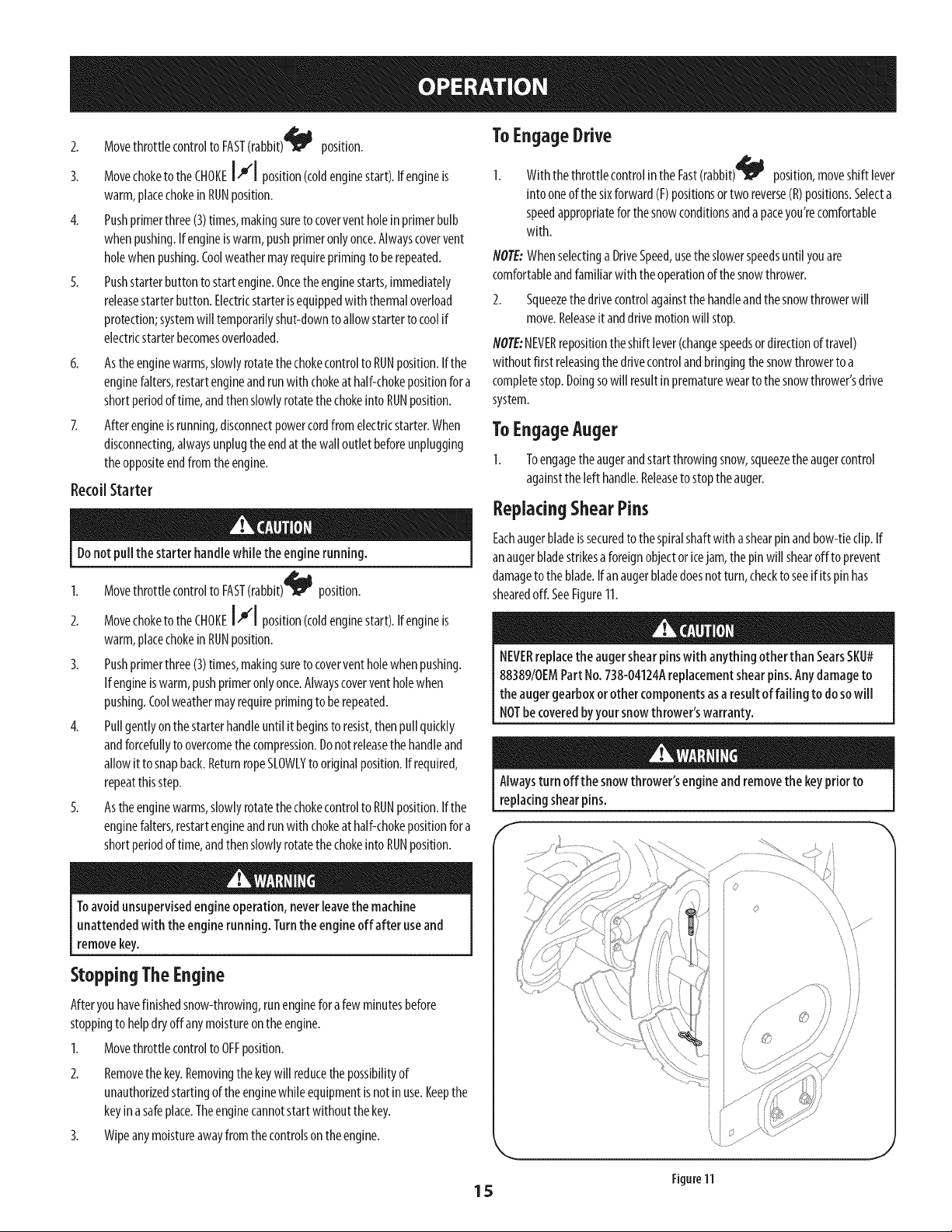
ReplacingShearPins
Eachaugerbladeissecuredto thespiralshaftwith ashearpinandbow-tieclip.If
anaugerbladestrikesa foreignobjectoricejam, the pinwill shearoff to prevent
damageto theblade.Ifan augerbladedoesnot turn, checkto seeif itspinhas
shearedoff. SeeFigure11.
NEVERreplacethe augershear pinswith anything otherthan SearsSKU#
88389/0EMPart No.738-04124Areplacementshearpins.Any damageto
the augergearboxor other componentsasa result of failing to do sowill
NOTbe coveredbyyour snowthrower'swarranty.
Alwaysturn off the snowthrower'sengineand removethe keypriorto
replacingshearpins.
J
Figure11
15
MAINTENANCESCHEDULE
Beforeperformingany typeof maintenance/service,disengageallcontrols
andstop the engine.Wait until all moving partshavecometo a complete
stop. Disconnectsparkplug wire and groundit againstthe engine to
preventunintendedstarting.
EachUseand every 5hours
Ist 5hours
Annuallyor25hours
Annuallyor50hours
Annuallyor100hours
BeforeStorage
Followthe maintenanceschedulegivenbelow.Thischartdescribesservice
guidelinesonly.Usethe ServiceLogcolumnto keeptrackofcompleted
maintenancetasks.Tolocatethe nearestSearsServiceCenteror to scheduleservice,
simplycontactSearsat 1-800-4-MY-HOME®.
1. Engineoil level
2. Looseormissinghardware
3. Unitandengine.
1. Englneoil
1. Sparkplug
2. Controllinkagesandpivots
3. Wheels
4. GearshaftandAugershaft
1. Englneoil
1. Sparkplug
1. Fuelsystem
GENERALRECOMMENDATIONS
CheckingEngineOil
Beforelubricating, repairing,or inspecting,disengageall controlsandstop
engine.Wait until all movingparts havecometo acompletestop.
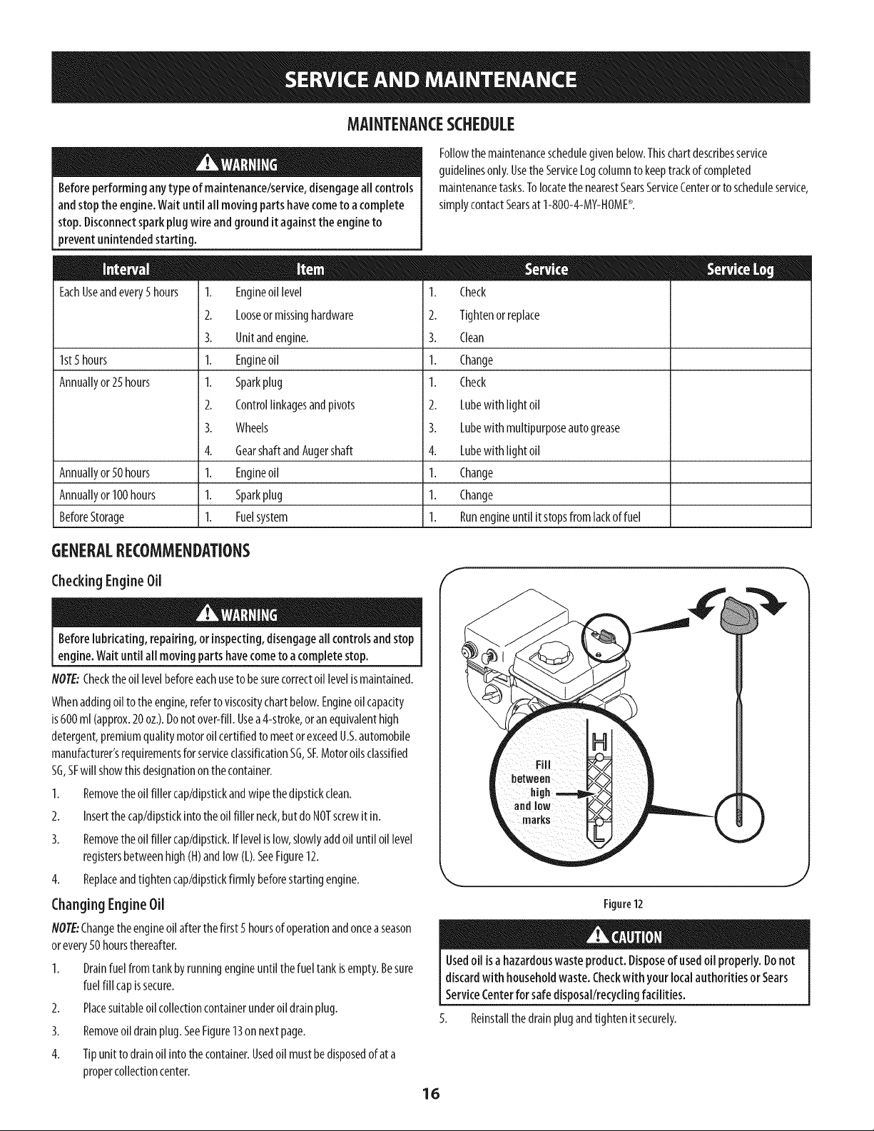
NOTE:Checkthe oil levelbeforeeachuseto besurecorrectoil levelismaintained.
Whenaddingoil to theengine,referto viscositychartbelow.Engineoil capacity
is600ml(approx.20oz.).Donot over-fill.Usea4-stroke,oranequivalenthigh
detergent,premiumquality motoroil certifiedto meetor exceedU.S.automobile
manufacturer'srequirementsforserviceclassificationSG,SF.Motoroilsclassified
SG,SFwill showthisdesignationon thecontainer.
1. Removetheoil filler cap/dipstkkandwipethedipstickclean.
2. Insertthe cap/dipstickintotheoil filler neck,but do NOTscrewit in.
3. Removetheoil filler cap/dipstick.Iflevelis low,slowlyaddoil until oil level
registersbetweenhigh(H)andlow (L).SeeFigure12.
4. Replaceandtightencap/dipstickfirmlybeforestartingengine.
Changing EngineOil
/VOTE."Changethe engineoil after thefirst 5 hoursof operationandoncea season
orevery50 hoursthereafter.
1. Drainfuel fromtank byrunningengineuntil thefueltankisempty.Besure
fuelfill capissecure.
2. Placesuitableoil collectioncontainerunderoil drainplug.
3. Removeoil drainplug.SeeFigure13on next page.
4. Tipunit to drainoil intothecontainer.Usedoil mustbedisposedofat a
propercollectioncenter.
1. Check
2. Tightenorreplace
3. Clean
1. Change
1. Check
2. Lubewith light oil
3. Lubewith multipurposeautogrease
4. Lubewith light oil
1. Change
1. Change
1. Runengineuntil itstopsfrom lackoffuel
Figure12
16
Usedoil isa hazardouswaste product. Disposeof usedoil properly.Donot
discardwith householdwaste. Checkwithyour localauthorities or Sears
ServiceCenterfor safedisposal/recyclingfacilities.
Reinstallthedrainplugandtightenitsecurely.
J
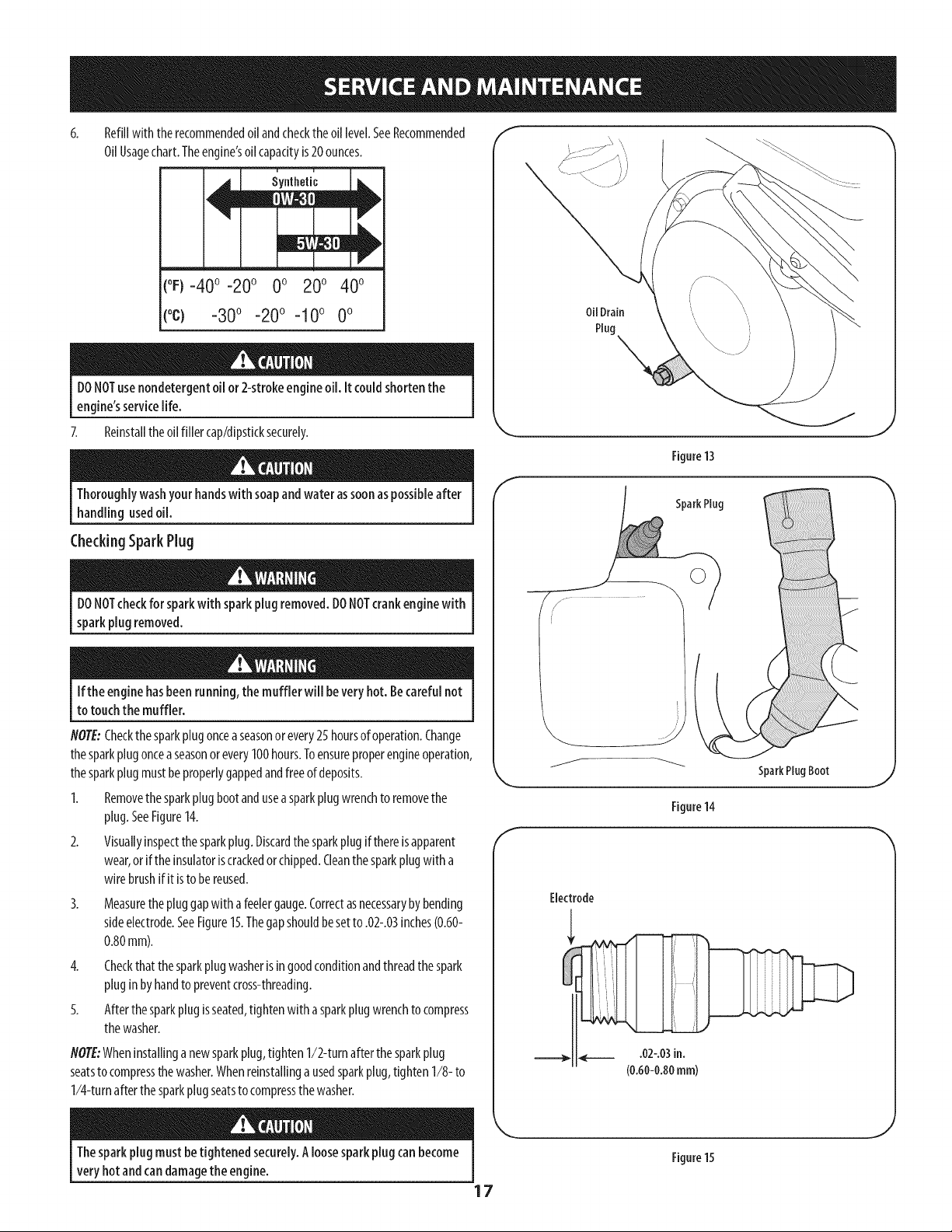
Refillwith therecommendedoil andcheckthe oil level.SeeRecommended
OilUsagechart.Theengine'soilcapacityis20ounces.
(oF)-40o-20 o 0o 20o 40o
(oc) -30° -20° -10 ° 0°
DONOTuse nondetergentoil or 2-strokeengineoil. it couldshorten the
engine'sservicelife.
7. Reinstallthe oil filler cap/dipsticksecurely.
Thoroughlywashyour handswith soapandwater assoonaspossibleafter
handlingusedoil.
CheckingSparkPlug
DONOTcheckfor sparkwith sparkplug removed.DONOTcrankenginewith
sparkplug removed.
Ifthe engine hasbeenrunning,the muffler will beveryhot. Becarefulnot
to touchthe muffler.
NOTE:Checkthesparkplugonceaseasonor every25hoursofoperation.Change
thesparkplugonceaseasonorevery100hours.Toensureproperengineoperation,
thesparkplugmustbeproperlygappedandfreeofdeposits.
1. Removethesparkplugbootandusea sparkplugwrenchtoremovethe
plug.SeeFigure14.
2. Visuallyinspectthesparkplug.Discardthesparkplugifthereisapparent
wear,orif theinsulatoriscrackedorchipped.Cleanthesparkplugwitha
wirebrushifit istobereused.
3.
Measurethe pluggapwith afeelergauge.Correctasnecessarybybending
sideelectrode.SeeFigure15.Thegapshouldbesetto .02-.03inches(0.60-
0.80mm).
4. Checkthatthesparkplug washerisin goodconditionandthreadthespark
pluginbyhandto preventcross-threading.
5. Afterthe sparkplugisseated,tightenwith asparkplugwrenchto compress
thewasher.
NOTE:Wheninstallinganewsparkplug,tighten 1/2-turnafterthesparkplug
seatsto compressthewasher.Whenreinstallinga usedsparkplug,tighten1/8- to
1/4-turnafterthesparkplugseatsto compressthewasher.
Oil Drain
Plug \
Figure13
E
SparkPlug
SparkPlugBoot
Figure14
Thesparkplug mustbe tightened securely.Aloosesparkplugcan become
very hotandcan damagethe engine.
17
Figure15
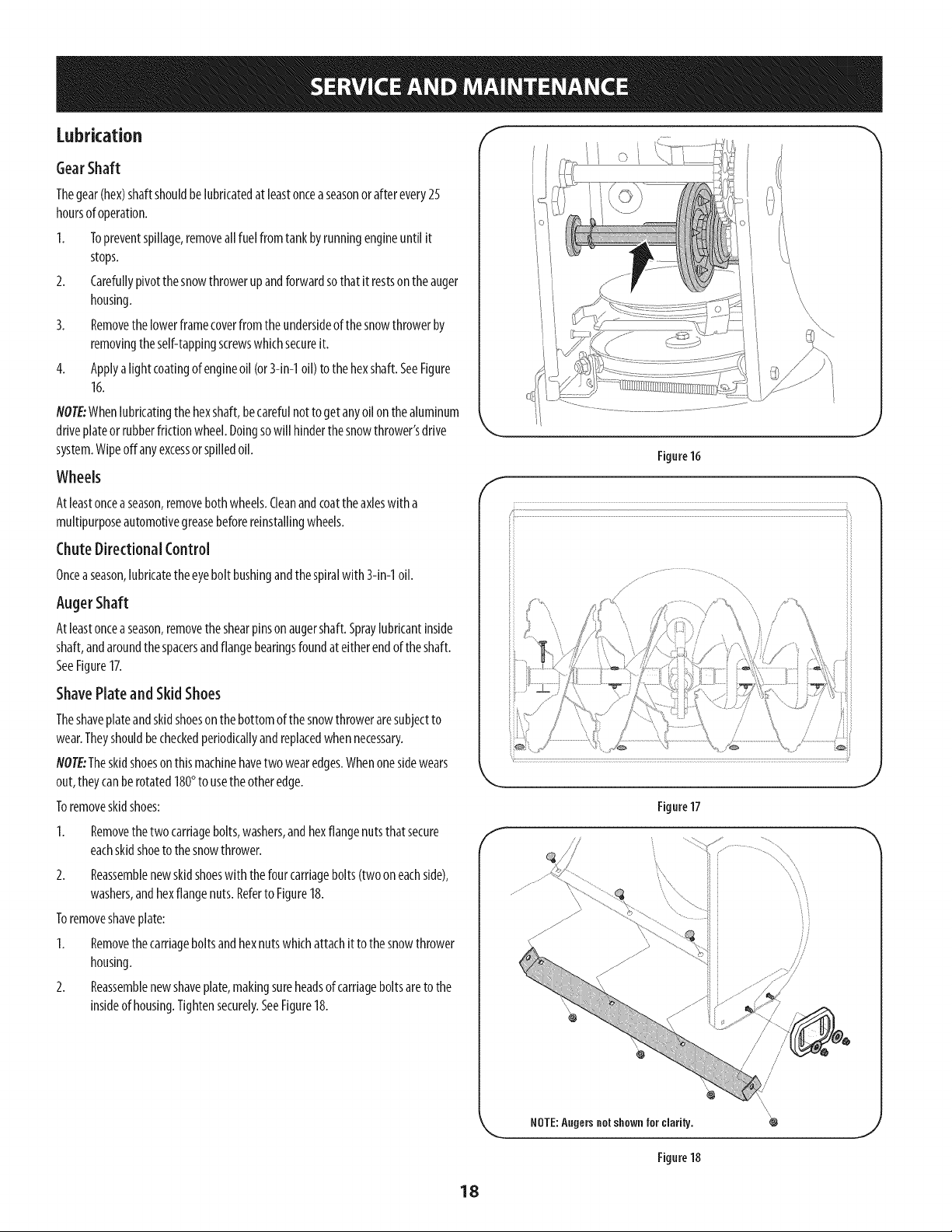
Lubrication "I
GearShaft
Thegear(hex)shaftshouldbelubricatedat leastonceaseasonor after every25
hoursof operation.
I. Topreventspillage,removeallfuel fromtank byrunningengineuntil it
stops.
2. Carefullypivotthesnowthrowerupandforwardsothat it restsonthe auger
housing.
3. Removethelowerframecoverfrom theundersideof thesnowthrowerby
removingtheself-tappingscrewswhichsecureit.
4. Applya lightcoatingof engineoil (or3-in-1oil) to the hexshaft.SeeFigure
16.
NOTE:Whenlubricatingthe hexshaft,becarefulnot to getanyoil onthealuminum
driveplateorrubberfrictionwheel.Doingsowill hinderthe snowthrower'sdrive
system.Wipeoffany excessor spilledoil.
Wheels
Atleastonceaseason,removebothwheels.Cleanandcoattheaxleswitha
multipurposeautomotivegreasebeforereinstallingwheels.
ChuteDirectional Control
Onceaseason,lubricatetheeyeboltbushingandthespiralwith 3-in-1oil.
AugerShaft
Atleastonceaseason,removethe shearpinson augershaft.Spraylubricantinside
shaft,andaroundthe spacersandflangebearingsfoundat eitherendof theshaft.
SeeFigure17.
ShavePlate and Skid Shoes
Theshaveplateandskidshoeson the bottomofthesnowthroweraresubjectto
wear.Theyshouldbecheckedperiodkallyandreplacedwhennecessary.
flOTE:Theskidshoeson thismachinehavetwo wearedges.Whenonesidewears
out,theycanberotated180°to usethe otheredge.
Toremoveskidshoes:
Removethetwocarriagebolts,washers,andhexflangenutsthatsecure
eachskidshoetothesnowthrower.
2. Reassemblenewskidshoeswith thefourcarriagebolts(two on eachside),
washers,andhexflangenuts.Referto Figure18.
Toremoveshaveplate:
1. Removethecarriageboltsandhexnutswhichattachit to thesnowthrower
housing.
2. Reassemblenewshaveplate,makingsureheadsof carriageboltsareto the
insideof housing.Tightensecurely.SeeFigure18.
f
Figure16
J
f_S /
f
Figure17
NOTE:Angers not shown for clarity.
4_
Figure18
18
Adjustments f
Shift Cable
I.
2.
3.
4.
Drive
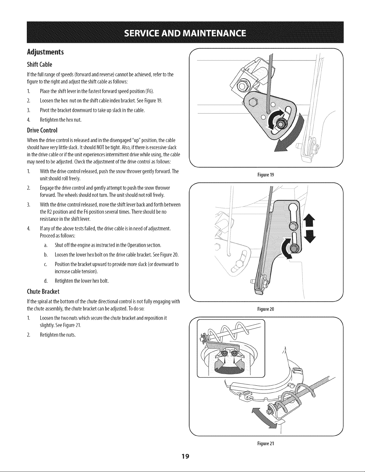
If thefull rangeof speeds(forwardandreverse)cannotbeachieved,referto the
figureto theright andadjusttheshift cableasfollows:
Placetheshift leverinthe fastestforwardspeedposition(F6).
Loosenthehex nutonthe shift cableindexbracket.SeeFigure19.
Pivotthe bracketdownwardtotakeupslackinthe cable.
Retightenthehexnut.
Control
Whenthedrivecontrolis releasedandinthe disengaged"up" position,the cable
shouldhaveverylittle slack.ItshouldNOTbetight. Also,if thereisexcessiveslack
inthedrivecableor iftheunit experiencesintermittentdrivewhileusing,thecable
mayneedto beadjusted.Checktheadjustmentof thedrivecontrolasfollows:
1. With thedrivecontrolreleased,pushthe snowthrowergentlyforward.The
unit shouldroll freely.
2. Engagethe drivecontrolandgentlyattemptto pushthesnowthrower
forward.Thewheelsshouldnot turn. Theunit shouldnotroll freely.
3. With thedrivecontrolreleased,movetheshift leverbackandforth between
theR2positionandthe F6positionseveraltimes.Thereshouldbeno
resistancein theshift lever.
4.
If anyof theabovetestsfailed,thedrivecableisinneedof adjustment.
Proceedasfollows:
a. Shutoff theengineasinstructedinthe Operationsection.
b. Loosenthe lowerhexbolt onthedrivecablebracket.SeeFigure20.
c. Positionthebracketupwardto providemoreslack(ordownwardto
increasecabletension).
d. Retightenthe lowerhexbolt.
ChuteBracket
If thespiralat thebottomofthechutedirectionalcontrolisnot fullyengagingwith
thechuteassembly,the chutebracketcanbeadjusted.Todoso:
1. Loosenthe two nutswhichsecurethe chutebracketandrepositionit
slightly.SeeFigure21.
2. Retightenthe nuts.
Figure19
Figure20
Figure21
19
AugerControl
Referto theAssemblysectionforinstructionsonadjustingtheaugercontrolcable.
Skid Shoes
Referto theAssemblysectionforinstructionsonadjustingtheskidshoes.
8eR Replacement
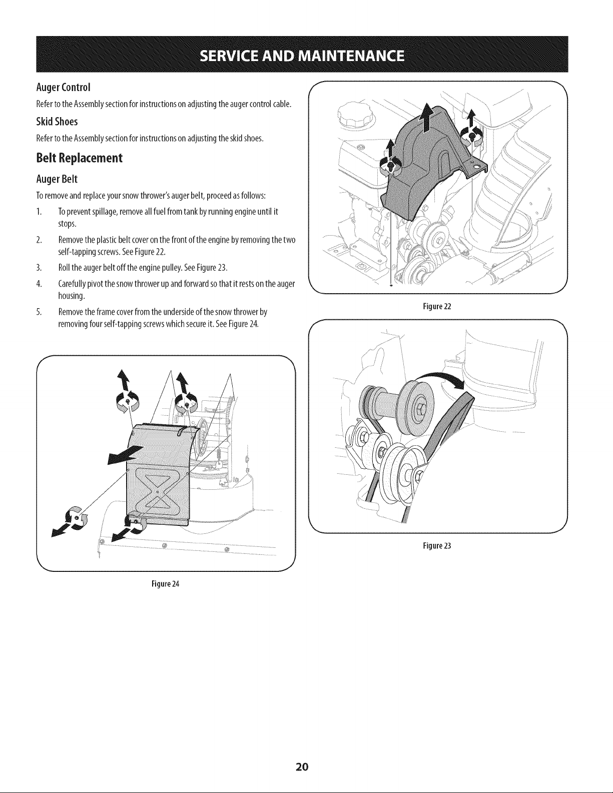
Auger Belt
Toremoveandreplaceyoursnowthrower'saugerbelt,proceedasfollows:
I. Topreventspillage,removeallfuel fromtank byrunningengineuntil it
stops.
2. Removetheplasticbelt coveronthe front of theenginebyremovingthetwo
self-tappingscrews.SeeFigure22.
3. Rolltheaugerbeltoffthe enginepulley.SeeFigure23.
4. Carefullypivotthesnowthrowerupandforwardsothat it restsonthe auger
housing.
5. Removetheframecoverfromthe undersideof thesnowthrowerby
removingfourself-tappingscrewswhichsecureit. SeeFigure24.
f
Figure 22
J
Figure 23
J
Figure24
.J
2O
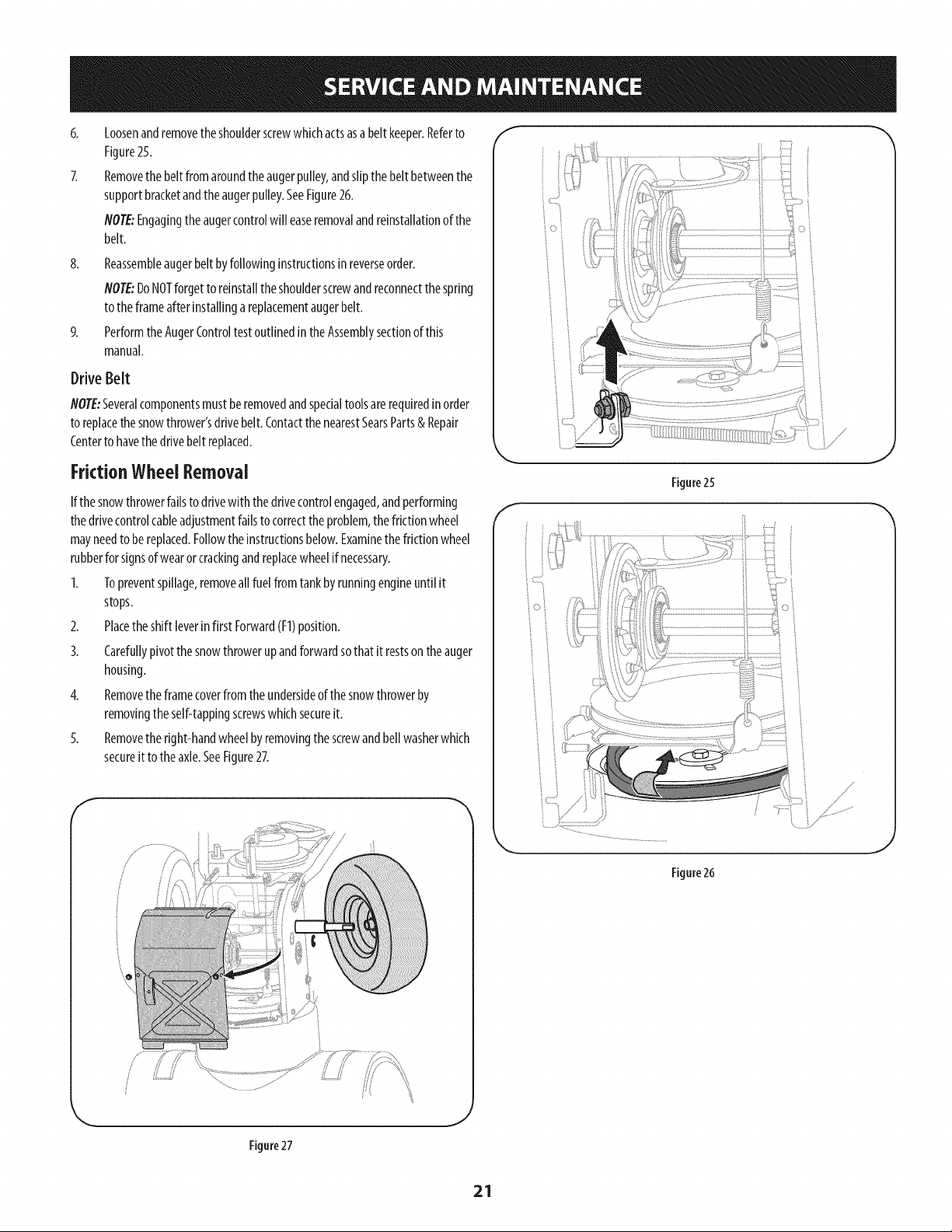
8.
Loosenandremovetheshoulderscrewwhichactsasabelt keeper.Referto
Figure25.
Removethe belt fromaroundtheaugerpulley,andslipthebelt betweenthe
supportbracketandtheaugerpulley.SeeFigure26.
NOTE:Engagingtheaugercontrolwill easeremovalandreinstallationof the
belt.
Reassembleaugerbeltbyfollowinginstructionsinreverseorder.
flOTE:DoNOTforgetto reinstalltheshoulderscrewandreconnectthespring
to theframeafterinstallingareplacementaugerbelt.
PerformtheAugerControltestoutlinedintheAssemblysectionof this
manual.
Drive Belt
flOTE:Severalcomponentsmustberemovedandspecialtoolsarerequiredin order
to replacethesnowthrower'sdrivebelt.Contactthe nearestSearsParts& Repair
Centerto havethedrivebelt replaced.
FrictionWheel Removal
If thesnowthrowerfailsto drivewith thedrivecontrolengaged,andperforming
thedrivecontrolcableadjustmentfailsto correctthe problem,thefrictionwheel
mayneedto bereplaced.Followtheinstructionsbelow.Examinethe frictionwheel
rubberfor signsofwearorcrackingandreplacewheelif necessary.
1. Topreventspillage,removeallfuel fromtankbyrunningengineuntil it
stops.
2. Placethe shift leverinfirst Forward(F1)position.
3. Carefullypivotthesnowthrowerupandforwardsothat it restson theauger
housing.
4. Removetheframecoverfromthe undersideof thesnowthrowerby
removingtheself-tappingscrewswhichsecureit.
5. Removetheright-handwheelbyremovingthescrewandbellwasherwhich
secureitto theaxle.SeeFigure27.
\
0 i
Figure25
Figure26
Figure27
21
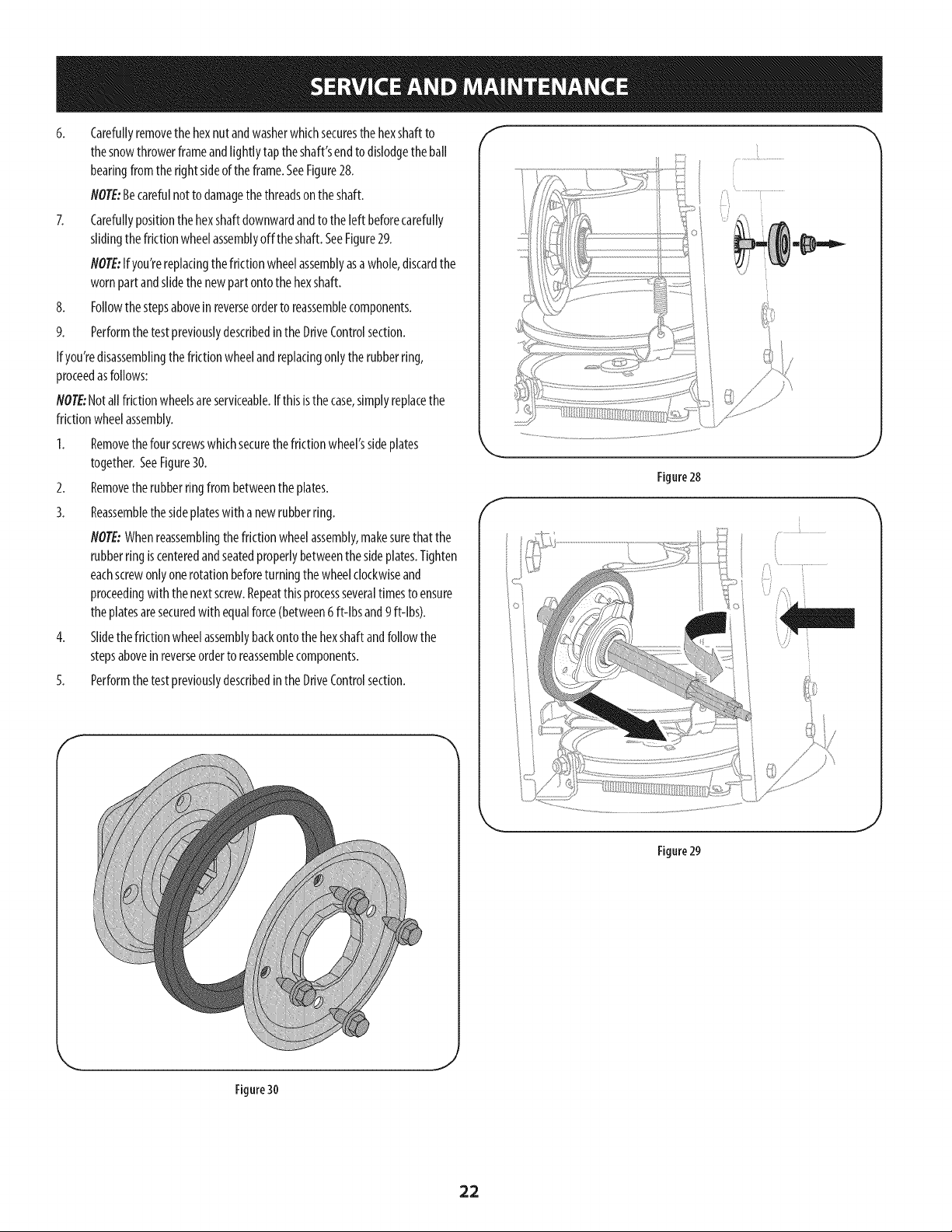
6. Carefullyremovethehexnutandwasherwhichsecuresthehexshaftto
thesnowthrowerframeandtightlytap theshaft'sendto dislodgetheban
bearingfromthe rightsideof the frame.SeeFigure28.
NOTE:Becarefulnot to damagethethreadsonthe shaft.
7. Carefullypositionthe hexshaftdownwardandto the [eftbeforecarefuNy
slidingthefrictionwheelassemblyoff theshaft.SeeFigure29.
NOTE:Ifyou'rereplacingthefrictionwheelassemblyasawhole,discardthe
wornpartandslidethe newpart ontothehexshaft.
8. Followthestepsaboveinreverseorderto reassemblecomponents.
9. Performthe testpreviouslydescribedinthe DriveControlsection.
If you'redisassemblingthefrictionwheelandreplacingonlythe rubberring,
proceedasfollows:
NOTE:Notallfrictionwheelsareserviceable.Ifthisisthecase,simplyreplacethe
frictionwheelassembly.
1. Removethefourscrewswhichsecurethefriction wheel'ssideplates
together.SeeFigure30.
2. Removetherubberringfrom betweenthe plates.
3. Reassemblethesideplateswith a newrubberring.
NOTE:Whenreassemblingthefrictionwheelassembly,makesurethatthe
rubberring iscenteredandseatedproperlybetweenthe sideplates.Tighten
eachscrewonlyonerotationbeforeturningthewheelclockwiseand
proceedingwith thenext screw.Repeatthisprocessseveraltimesto ensure
theplatesaresecuredwith equalforce(between6 ft-lbsand9 ft-lbs).
4. Slidethefrictionwheelassemblybackontothehexshaftandfollowthe
stepsaboveinreverseorderto reassemblecomponents.
5. Performthe testpreviouslydescribedinthe DriveControlsection.
f
f
Figure 28
J
Figure29
J
Figure 30
,J
22
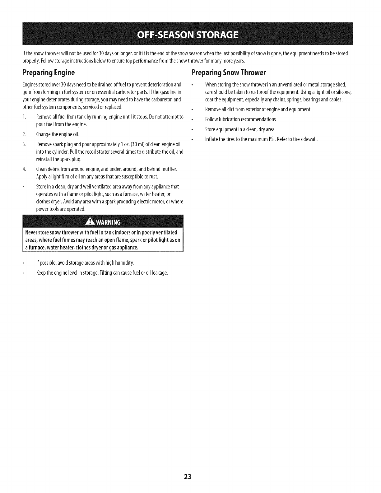
If thesnowthrowerwill notbeusedfor 30daysor longer,or if it is theendof thesnowseasonwhenthelastpossibilityof snowisgone,the equipmentneedsto bestored
properly.Followstorageinstructionsbelowto ensuretopperformancefrom thesnowthrowerformanymoreyears.
PreparingEngine
Enginesstoredover30daysneedto bedrainedof fuelto preventdeteriorationand
gumfromforminginfuel systemor on essentialcarburetorparts.If thegasolinein
yourenginedeterioratesduringstorage,youmayneedto havethecarburetor,and
otherfuelsystemcomponents,servicedor replaced.
1. Removeall fuel fromtank byrunningengineuntil it stops.Donotattemptto
pourfuelfrom theengine.
2. Changetheengineoil.
3. Removesparkplugandpourapproximately1oz.(30ml)ofcleanengineoil
into thecylinder.Pulltherecoilstarterseveraltimesto distributetheoil, and
reinstallthesparkplug.
4. Cleandebrisfromaroundengine,andunder,around,andbehindmuffler.
Applya lightfilm ofoil on anyareasthat aresusceptibleto rust.
Storeinaclean,dry andwell ventilatedareaawayfromanyappliancethat
operateswith aflameorpilot light,suchasa furnace,waterheater,or
clothesdryer.Avoidanyareawitha sparkproducingelectricmotor,orwhere
powertoolsareoperated.
PreparingSnowThrower
Whenstoringthe snowthrowerin anunventilatedormetalstorageshed,
careshouldbetakento rustprooftheequipment.Usinga lightoil orsilicone,
coattheequipment,especiallyanychains,springs,bearingsandcables.
Removeall dirt fromexteriorof engineandequipment.
Followlubricationrecommendations.
Storeequipmentinaclean,dry area.
Inflatethe tiresto themaximumPSI.Referto tire sidewall.
Neverstore snowthrower with fuel intank indoorsor in poorlyventilated
areas,wherefuel fumes mayreachan openflame, sparkor pilotlight ason
a furnace,water heater,clothesdryeror gasappliance.
If possible,avoidstorageareaswith highhumidity.
Keeptheenginelevelinstorage.Tiltingcancausefueloroil leakage.
23
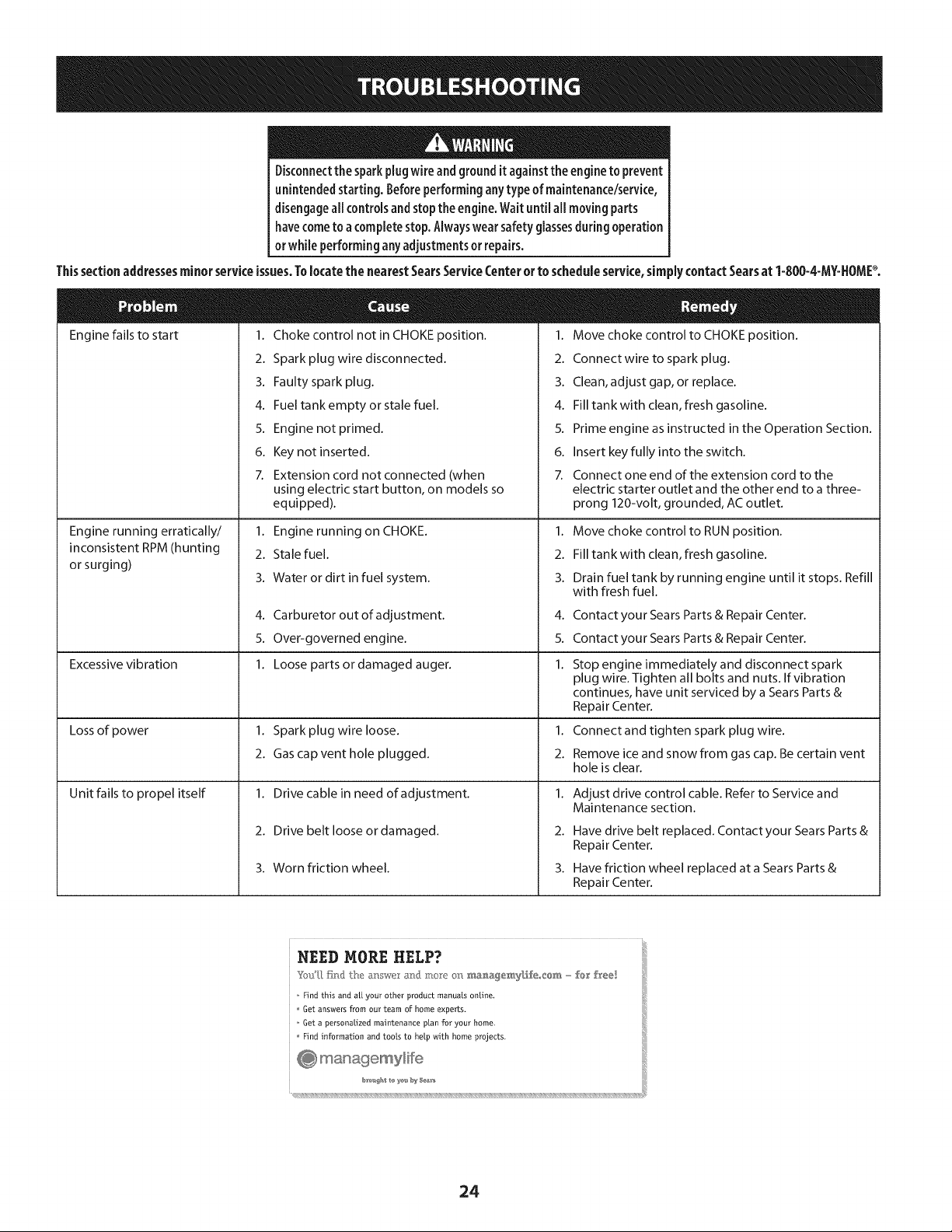
Disconnectthe sparkplug wireandgroundit againstthe engineto prevent
unintendedstarting. Beforeperforminganytypeof maintenance/service,
disengageall controls andstopthe engine.Wait until aHmovingparts
havecometo a completestop.Alwayswear safetyglassesduringoperation
or while performingany adjustmentsor repairs.
Thissectionaddressesminorserviceissues.Tolocatethe nearestSearsServiceCenterorto scheduleservice,simplycontactSearsat 1-800-4-MY=HOMP.
Engine fails to start 1.
2.
3.
4.
5.
6.
7.
Choke control not in CHOKE position.
Spark plug wire disconnected.
Faulty spark plug.
Fuel tank empty or stale fuel.
Engine not primed.
Key not inserted.
Extension cord not connected (when
1. Move choke control to CHOKE position.
2. Connectwire to spark plug.
3. Clean, adjust gap, or replace.
4. Fill tank with clean, fresh gasoline.
5. Prime engine as instructed in the Operation Section.
6. Insert key fully into the switch.
7. Connect one end of the extension cord to the
Engine running erratically/
inconsistent RPM (hunting
or surging)
Excessive vibration
Lossof power
Unit fails to propel itself
using electric start button, on models so
equipped).
1. Engine running on CHOKE.
2. Stale fuel.
3. Water or dirt in fuel system.
4. Carburetor out of adjustment.
5. Over-governed engine.
1. Loose parts or damaged auger.
1. Spark plug wire loose.
2. Gas cap vent hole plugged.
1. Drive cable in need of adjustment.
2. Drive belt loose or damaged.
3. Worn friction wheel.
electric starter outlet and the other end to a three-
prong 120-volt, grounded, ACoutlet.
1. Move choke control to RUN position.
2. Fill tank with clean, fresh gasoline.
3. Drain fuel tank by running engine until it stops. Refill
with fresh fuel.
4.
5.
1.
1.
2.
1.
2.
3.
Contact your Sears Parts & Repair Center.
Contact your Sears Parts & Repair Center.
Stop engine immediately and disconnect spark
plug wire. Tighten all bolts and nuts. If vibration
continues, have unit serviced by a Sears Parts &
Repair Center.
Connect and tighten spark plug wire.
Remove ice and snow from gas cap. Be certain vent
hole is clear.
Adjust drive control cable. Refer to Service and
Maintenance section.
Have drive belt replaced. Contact your Sears Parts &
Repair Center.
Have friction wheel replaced at a Sears Parts &
Repair Center.
NEED MORE HELP?
Find this and a[[ your other product manuals online,
Get answers from our team of home experts.
Get a personalized maintenance plan for your home.
Find information and tools to help Mth home projects.
24
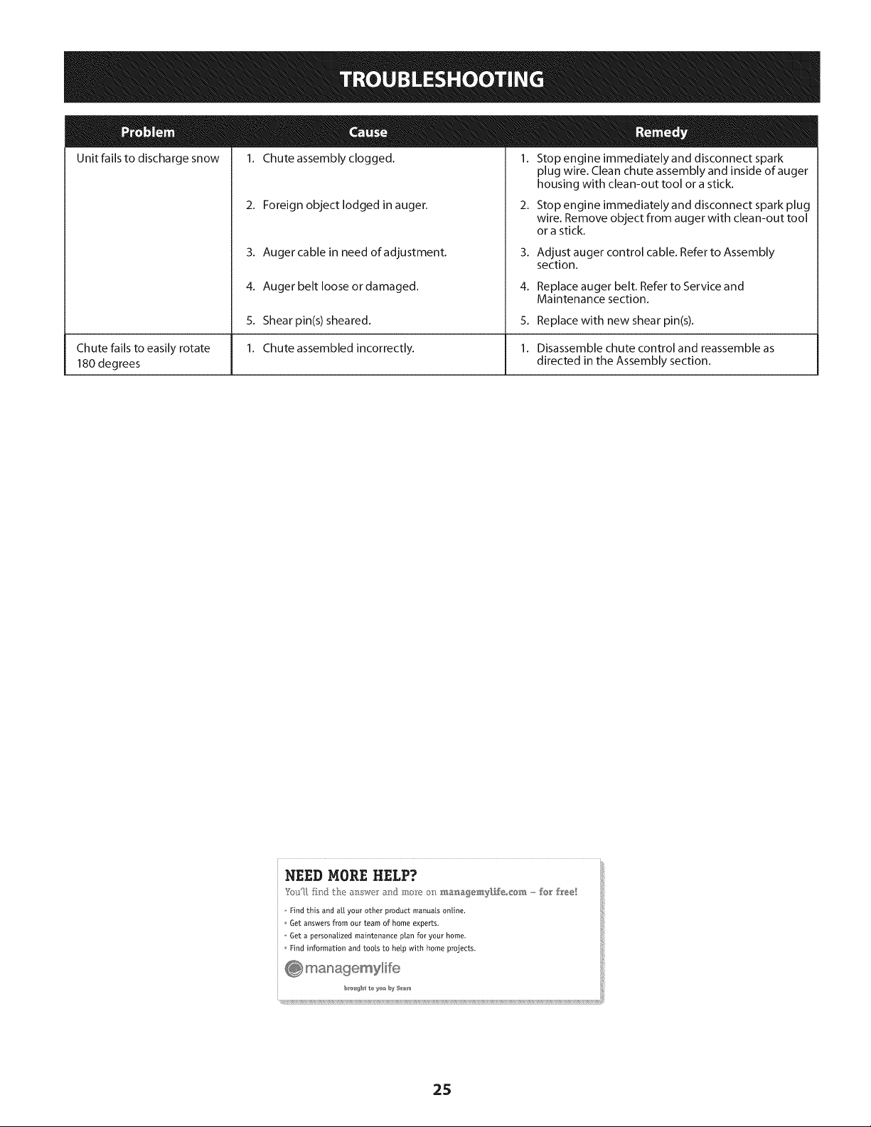
Unit fails to discharge snow
Chute fails to easily rotate
180 degrees
1. Chute assembly clogged. 1. Stop engine immediately and disconnect spark
2. Foreign object lodged in auger.
3. Auger cable in need of adjustment.
4. Auger belt loose or damaged.
5. Shearpin(s) sheared.
1. Chute assembled incorrectly.
plug wire. Clean chute assembly and inside of auger
housing with clean-out tool or a stick.
2. Stop engine immediately and disconnect spark plug
wire. Remove object from auger with clean-out tool
or a stick.
3. Adjust auger control cable. Refer to Assembly
section.
4. Replace auger belt. Refer to Service and
Maintenance section.
5. Replace with new shear pin(s).
1. Disassemble chute control and reassemble as
directed in the Assembly section.
NEED MORE HELP?
YotJU,fir_} the _: swe a_] :m,_"Yeo_:__._a_,a_emy[f_eo_@_,,,,,,,fo_' free!
o Find this and a[[ your other product manuals online.
Get answers from our team of home experts,
o Get a personalized maintenance plan for your home_
Find information and tools to help with home projects.
25
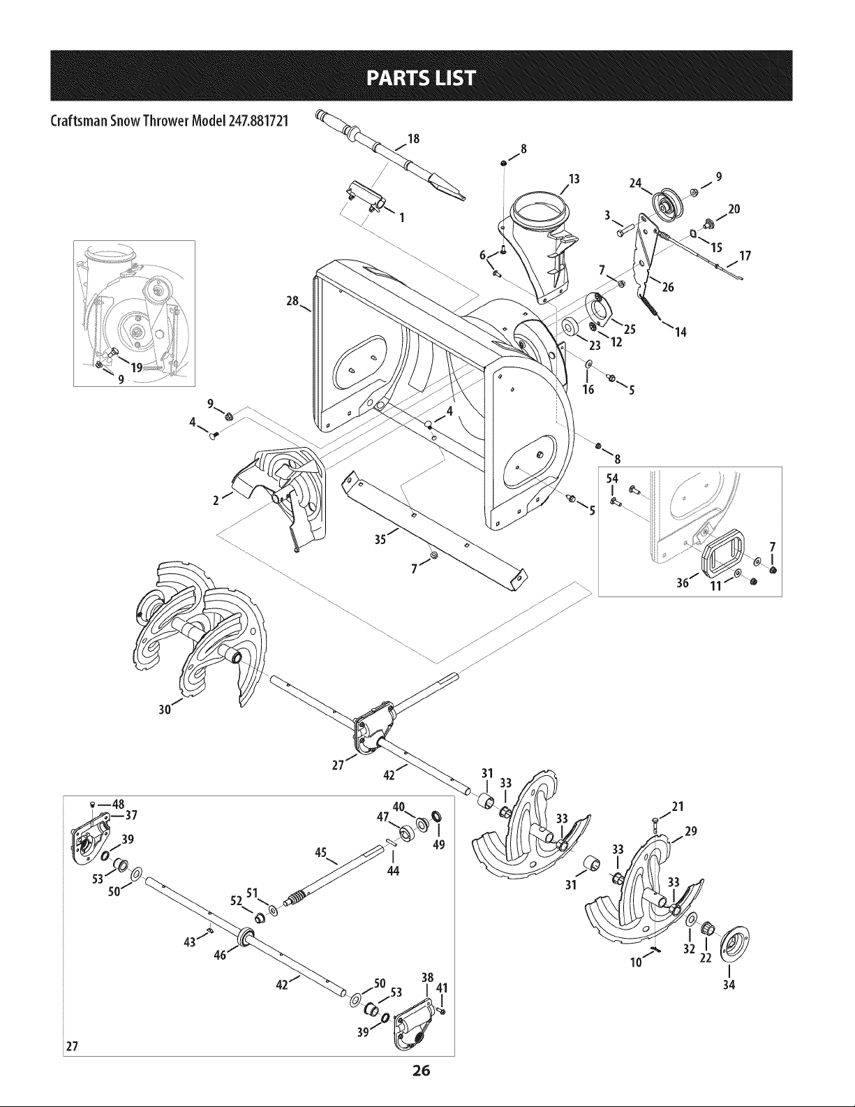
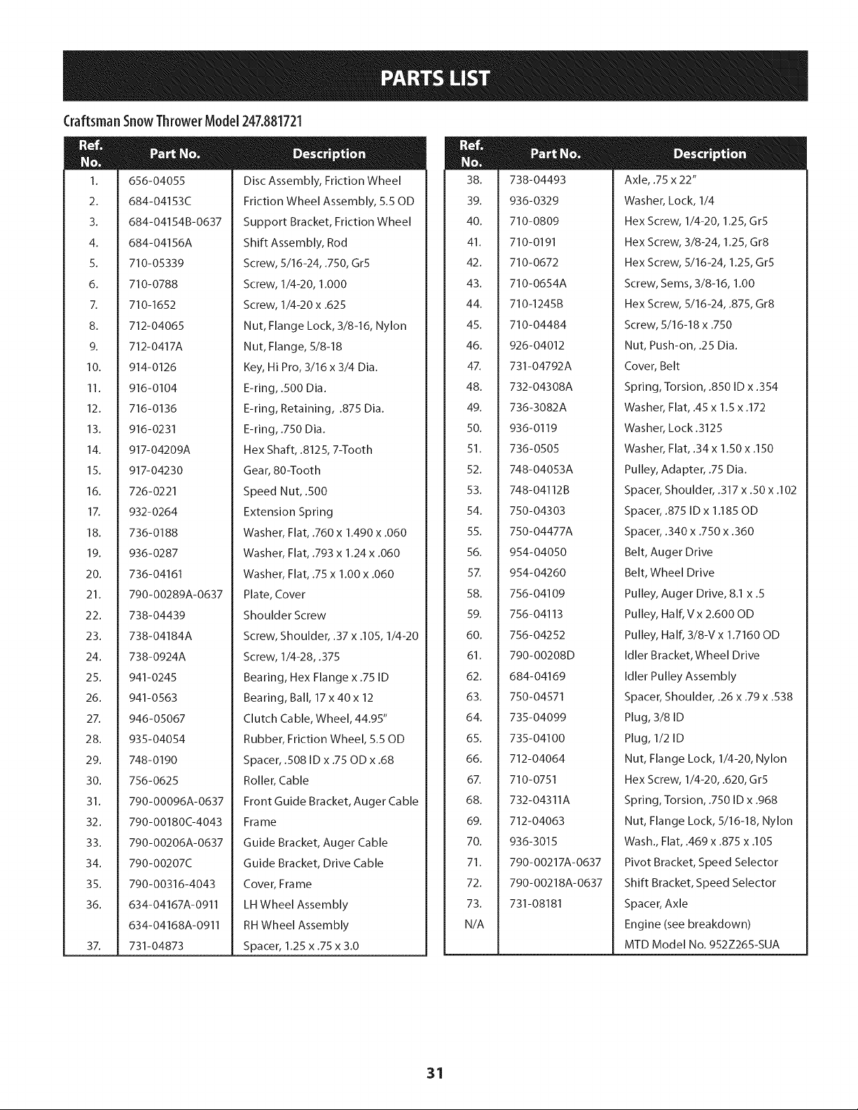
CraftsmanSnowThrowerModel 247.881721
18
/
_\\/ 1
\\\\
8
o,/"
15
17
514 /
36/
i27
26
31
31
21
_"/ 29
J
33
I
34
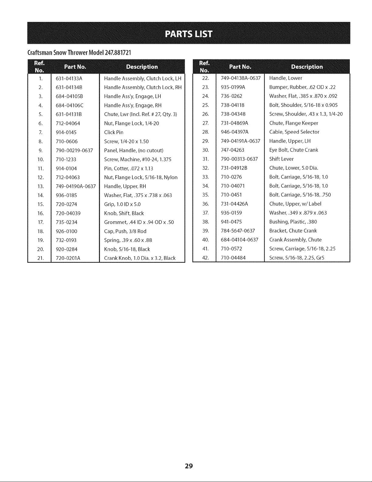
Craftsman SnowThrowerModel 247.881721
m
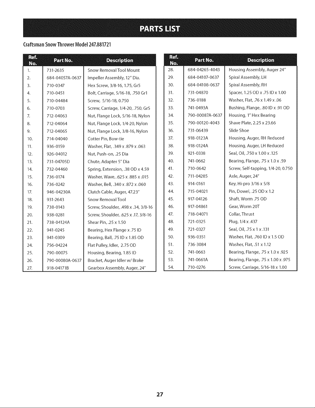
1.
2.
3.
4.
5.
6.
7.
8.
9.
10.
11.
12.
13.
14.
15.
16.
17.
18.
19.
20.
21.
22.
23.
24.
25.
26.
27.
731-2635
684-04057A-0637
710-0347
710-0451
710-04484
710-0703
712-04063
712-04064
712-04065
714-04040
936-0159
926-04012
731-04705D
732-04460
736-0174
736-0242
946-04230A
931-2643
738-0143
938-0281
738-04124A
941-0245
941-0309
756-04224
790-00075
790-00080A-0637
918- 04171B
Snow Removal Tool Mount
Impeller Assembly, 12" Dia.
Hex Screw, 3/8-16, 1.75, Gr5
Bolt, Carriage, 5/16-18, .750 Grl
Screw, 5/16-18, 0.750
Screw, Carriage, 1/4-20, .750, Gr5
Nut, Flange Lock, 5/16-18, Nylon
Nut, Flange Lock, 1/4-20, Nylon
Nut, Flange Lock, 3/8-16, Nylon
Cotter Pin, Bow-tie
Washer, Flat, .349 x .879 x .063
Nut, Push-on, .25 Dia
Chute, Adapter 5" Dia
Spring, Extension, .38 OD x 4.59
Washer, Wave, .625 x .885 x .015
Washer, Bell, .340 x .872 x .060
Clutch Cable, Auger, 47.23"
Snow Removal Tool
Screw, Shoulder, .498 x .34, 3/8-16
Screw, Shoulder, .625 x .17, 3/8-16
Shear Pin, .25 x 1.50
Bearing, Hex Flange x .75 ID
Bearing, Ball, .75 ID x 1.85 OD
Flat Pulley, Idler, 2.75 OD
Housing, Bearing, 1.85 ID
Bracket, Auger Idler w/Brake
Gearbox Assembly, Auger, 24"
M
28.
29.
30.
31.
32.
33.
34.
35.
36.
37.
38.
39.
40.
41.
42.
43.
44.
45.
46.
47.
48.
49.
50.
51.
52.
53.
54.
684-04265-4043
684-04107-0637
684-04108-0637
731-04870
736-0188
741-0493A
790-00087A-0637
790-00120-4043
731-06439
918-0123A
918-0124A
921-0338
741-0662
710-0642
711-04285
914-0161
715-04021
917-04126
917-04861
718-04071
721-0325
721-0327
936-0351
736-3084
741-0663
741-0661A
710-0276
Housing Assembly, Auger 24"
Spiral Assembly, LH
Spiral Assembly, RH
Spacer, 1.25 OD x .75 ID x 1.00
Washer, Flat, .76 x 1.49 x .06
Bushing, Flange, .80 ID x .91 OD
Housing, I" Hex Bearing
Shave Plate, 2.25 x 23.66
Slide Shoe
Housing, Auger, RH Reduced
Housing, Auger, LH Reduced
Seal, Oil, .750 x 1.00 x .125
Bearing, Flange, .75 x 1.0 x .59
Screw, Self-tapping, I/4-20, 0.750
Axle, Auger, 24"
Key, Hi-pro 3/16 x 5/8
Pin, Dowel, .25 OD x 1.2
Shaft, Worm .75 OD
Gear, Worm 20T
Collar, Thrust
Plug, I/4 x .437
Seal, Oil, .75 x I x .131
Washer, Flat, .760 ID x 1.50D
Washer, Flat, .51 x 1.12
Bearing, Flange, .75 x 1.0 x .925
Bearing, Flange, .75 x 1.00 x .975
Screw, Carriage, 5/16-18 x 1.00
27
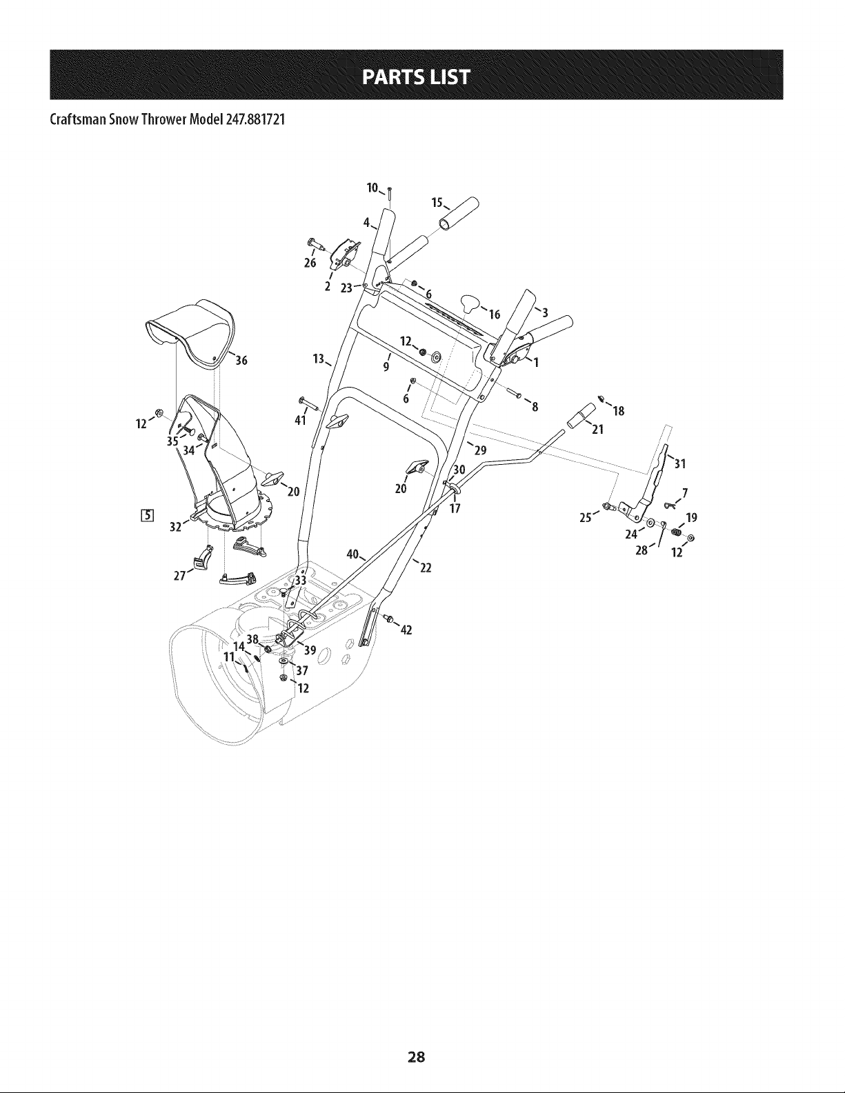
CraftsmanSnowThrowerModel247.881721
/
2
[]
17
12
37
28
Craftsman SnowThrowerModel247.881721
m
1.
2.
3.
4.
5.
6.
7.
8.
9.
10.
11.
12.
13.
14.
15.
16.
17.
18.
19.
20.
21.
631 -04133A
631-04134B
684-04105B
684-04106C
631-04131B
712-04064
914-0145
710-0606
790-00219-0637
710-1233
914-0104
712-04063
749-04190A-0637
936-0185
720-0274
720-04039
735-0234
926-0100
732-0193
920-0284
720-0201A
Handle Assembly, Clutch Lock, LH
Handle Assembly, Clutch Lock, RH
Handle Ass'y, Engage, LH
Handle Ass'y, Engage, RH
Chute, Lwr (Incl. Ref. # 27, Qty. 3)
Nut, Flange Lock, 1/4-20
Click Pin
Screw, 1/4-20 x 1.50
Panel, Handle, (no cutout)
Screw, Machine, #10-24, 1.375
Pin, Cotter, .072 x 1.13
Nut, Flange Lock, 5/16-18, Nylon
Handle, Upper, RH
Washer, Flat, .375 x .738 x .063
Grip, 1.0 ID x 5.0
Knob, Shift, Black
Grommet, .44 ID x .94 OD x .50
Cap, Push, 3/8 Rod
Spring, .39 x .60 x .88
Knob, 5/16-18, Black
Crank Knob, 1.0 Dia. x 3.2, Black
m
m
22.
23.
24.
25.
26.
27.
28.
29.
30.
31.
32.
33.
34.
35.
36.
37.
38.
39.
40.
41.
42.
749-04138A-0637
935-0199A
736-0262
738-04118
738-04348
731-04869A
946-04397A
749-04191A-0637
747-04263
790-00313-0637
Handle, Lower
Bumper, Rubber, .62 OD x .22
Washer, Flat, .385 x .870 x .092
Bolt, Shoulder, 5/16-18 x 0.905
Screw, Shoulder, .43 x 1.3, 1/4-20
Chute, Flange Keeper
Cable, Speed Selector
Handle, Upper, LH
Eye Bolt, Chute Crank
Shift Lever
731-04912B
710-0276
710-04071
710-0451
731-04426A
936-0159
941-0475
784-5647-0637
684-04104-0637
710-0572
710-04484
Chute, Lower, 5.0 Dia.
Bolt, Carriage, 5/16-18, 1.0
Bolt, Carriage, 5/16-18, 1.0
Bolt, Carriage, 5/16-18, .750
Chute, Upper, w/Label
Washer, .349 x .879 x .063
Bushing, Plastic, .380
Bracket, Chute Crank
Crank Assembly, Chute
Screw, Carriage, 5/16-18, 2.25
Screw, 5/16-18, 2.25, Gr5
29
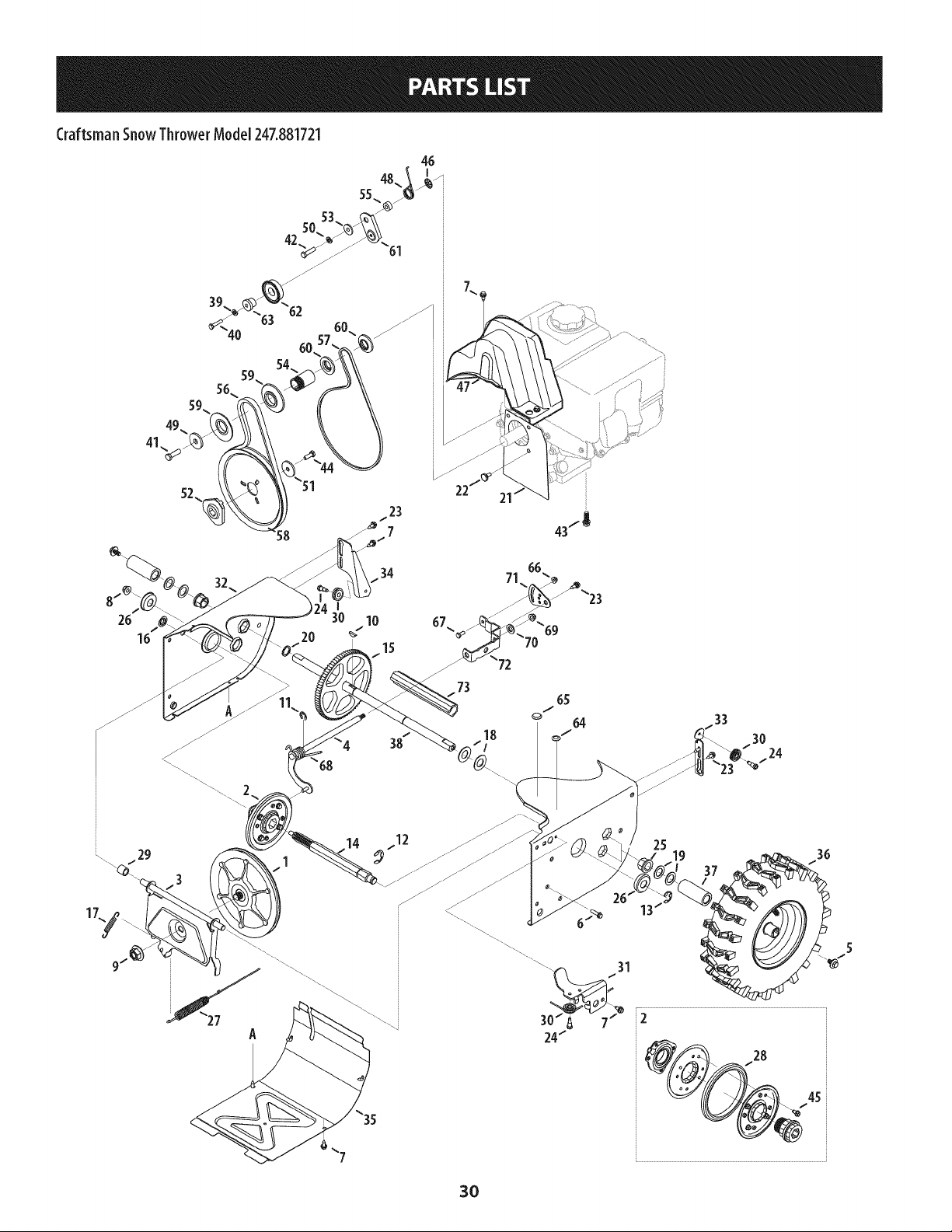
CraftsmanSnowThrowerModel247.881721
46
41,
/23
7
34
I
30 10
15
38
73
17
3O
Craftsman SnowThrowerModel247.881721
m
1.
2.
3.
4.
5.
6.
7.
8.
9.
10.
11.
12.
13.
14.
15.
16.
17.
18.
19.
20.
21.
22.
23.
24.
25.
26.
27.
28.
29.
30.
31.
32.
33.
34.
35.
36.
37.
656-04055
684-04153C
684-04154B-0637
684- 04156A
710-05339
710-0788
710-1652
712-04065
712-0417A
914-0126
916-0104
716-0136
916-0231
917-04209A
917-04230
726-0221
932-0264
736-0188
936-0287
736-04161
790-00289A-0637
738-04439
738-04184A
738-0924A
941-0245
941-0563
946-05067
935-04054
748-0190
756-0625
790-00096A-0637
790-00180C-4043
790-00206A-0637
790-00207C
790-00316-4043
634-04167A-0911
634-04168A-0911
731-04873
Disc Assembly, Friction Wheel
Friction Wheel Assembly, 5.50D
Support Bracket, Friction Wheel
Shift Assembly, Rod
Screw, 5/16-24, .750, Gr5
Screw, 1/4-20, 1.000
Screw, 1/4-20 x .625
Nut, Flange Lock, 3/8-16, Nylon
Nut, Flange, 5/8-18
Key, Hi Pro, 3/16 x 3/4 Dia.
E-ring, .500 Dia.
E-ring, Retaining, .875 Dia.
E-ring, .750 Dia.
Hex Shaft, .8125, 7-Tooth
Gear, 80-Tooth
Speed Nut, .500
Extension Spring
Washer, Flat, .760 x 1.490 x .060
Washer, Flat, .793 x 1.24 x .060
Washer, Flat, .75 x 1.00 x .060
Plate, Cover
Shoulder Screw
Screw, Shoulder, .37 x .105, 1/4-20
Screw, 1/4-28, .375
Bearing, Hex Flange x .75 ID
Bearing, Ball, 17 x 40 x 12
Clutch Cable, Wheel, 44.95"
Rubber, Friction Wheel, 5.50D
Spacer, .508 ID x .75 OD x .68
Roller, Cable
Front Guide Bracket, Auger Cable
Frame
Guide Bracket, Auger Cable
Guide Bracket, Drive Cable
Cover, Frame
LH Wheel Assembly
RH Wheel Assembly
Spacer, 1.25 x .75 x 3.0
m
m
38.
39.
40.
41.
42.
43.
44.
45.
46.
47.
48.
49.
50.
51.
52.
53.
54.
55.
56.
57.
58.
59.
60.
61.
62.
63.
64.
65.
66.
67.
68.
69.
70.
71.
72.
73.
N/A
738-04493
936-0329
710-0809
710-0191
710-0672
710-0654A
710-1245B
710-04484
926-04012
731-04792A
732-04308A
736-3082A
936-0119
736-0505
748-04053A
748-04112B
750-04303
750-04477A
954-04050
954-04260
756- 04109
756- 04113
756-04252
790-00208D
684-04169
750-04571
735-04099
735-04100
712-04064
710-0751
732-04311A
712-04063
936-3015
Axle, .75 x 22"
Washer, Lock, 1/4
Hex Screw, 1/4-20, 1.25, Gr5
Hex Screw, 3/8-24, 1.25, Gr8
Hex Screw, 5/16-24, 1.25, Gr5
Screw, Seres, 3/8-16, 1.00
Hex Screw, 5/16-24, .875, Gr8
Screw, 5/16-18 x .750
Nut, Push-on, .25 Dia.
Cover, Belt
Spring, Torsion, .850 ID x .354
Washer, Flat, .45 x 1.5 x .172
Washer, Lock .3125
Washer, Flat, .34 x 1.50 x .150
Pulley, Adapter, .75 Dia.
Spacer, Shoulder, .317 x .50 x .102
Spacer, .875 ID x 1.185 OD
Spacer, .340 x .750 x .360
Belt, Auger Drive
Belt, Wheel Drive
Pulley, Auger Drive, 8.1 x .5
Pulley, Half, V x 2.600 OD
Pulley, Half, 3/8-V x 1.7160 OD
Idler Bracket, Wheel Drive
Idler Pulley Assembly
Spacer, Shoulder, .26 x .79 x .538
Plug, 3/8 ID
Plug, 1/2 ID
Nut, Flange Lock, 1/4-20, Nylon
Hex Screw, 1/4-20, .620, Gr5
Spring, Torsion, .750 ID x .968
Nut, Flange Lock, 5/16-18, Nylon
Wash., Flat, .469 x .875 x .105
790-00217A-0637
790-00218A-0637
731-08181
Pivot Bracket, Speed Selector
Shift Bracket, Speed Selector
Spacer, Axle
Engine (see breakdown)
MTD Model No. 952Z265-SUA
31
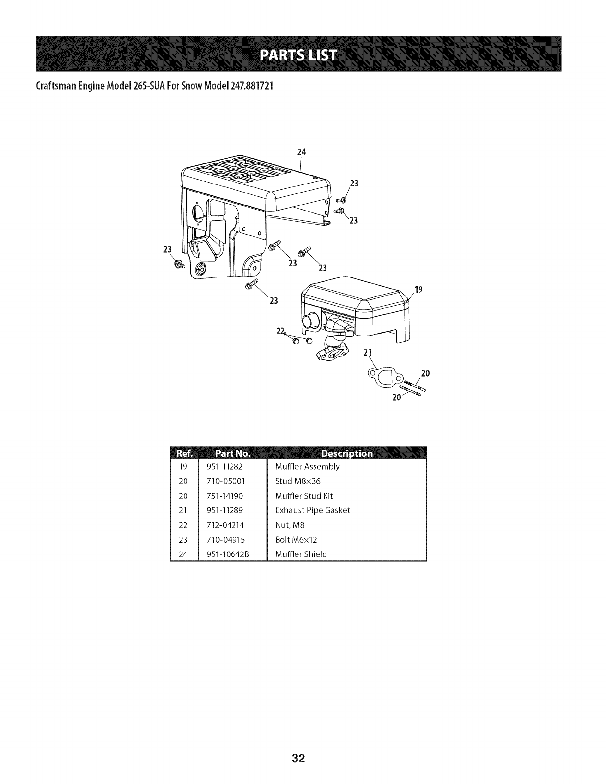
CraftsmanEngineModel265-SUAForSnowModel247.881721
24
23
m
19
20
20
21
22
23
24
951-11282
710-05001
751-14190
951-11289
712-04214
710-04915
951-I0642B
D _ o O
Muffler Assembly
Stud M8x36
Muffler Stud Kit
Exhaust Pipe Gasket
Nut, M8
Bolt M6x12
Muffler Shield
32
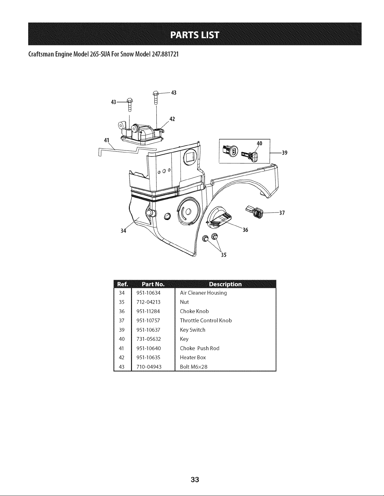
Craftsman EngineModel 265-SUAForSnowModel 247.881721
41 _42
°0
37
35
34
35
36
37
39
4O
41
42
43
951-10634
712-04213
951-11284
951-10757
951-10637
731-05632
951-10640
951-10635
710-04943
D _ o 0
Air Cleaner Housing
Nut
Choke Knob
Throttle Control Knob
Key Switch
Key
Choke Push Rod
Heater Box
Bolt M6x28
33
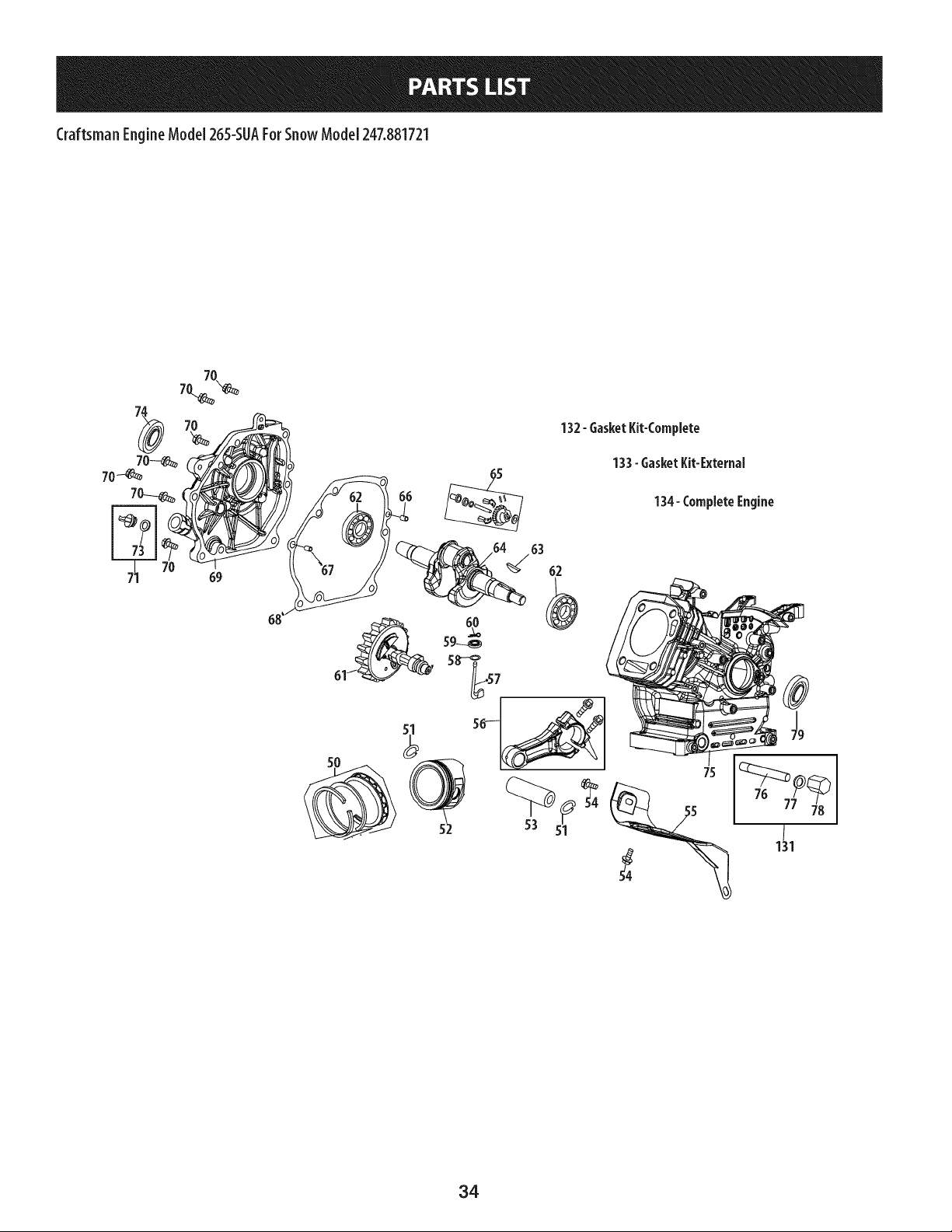
Craftsman EngineModel265-SUAFor SnowModel 247.881721
132- GasketKit-Complete
133- GasketKit-External
134-CompleteEngine
63
62
34
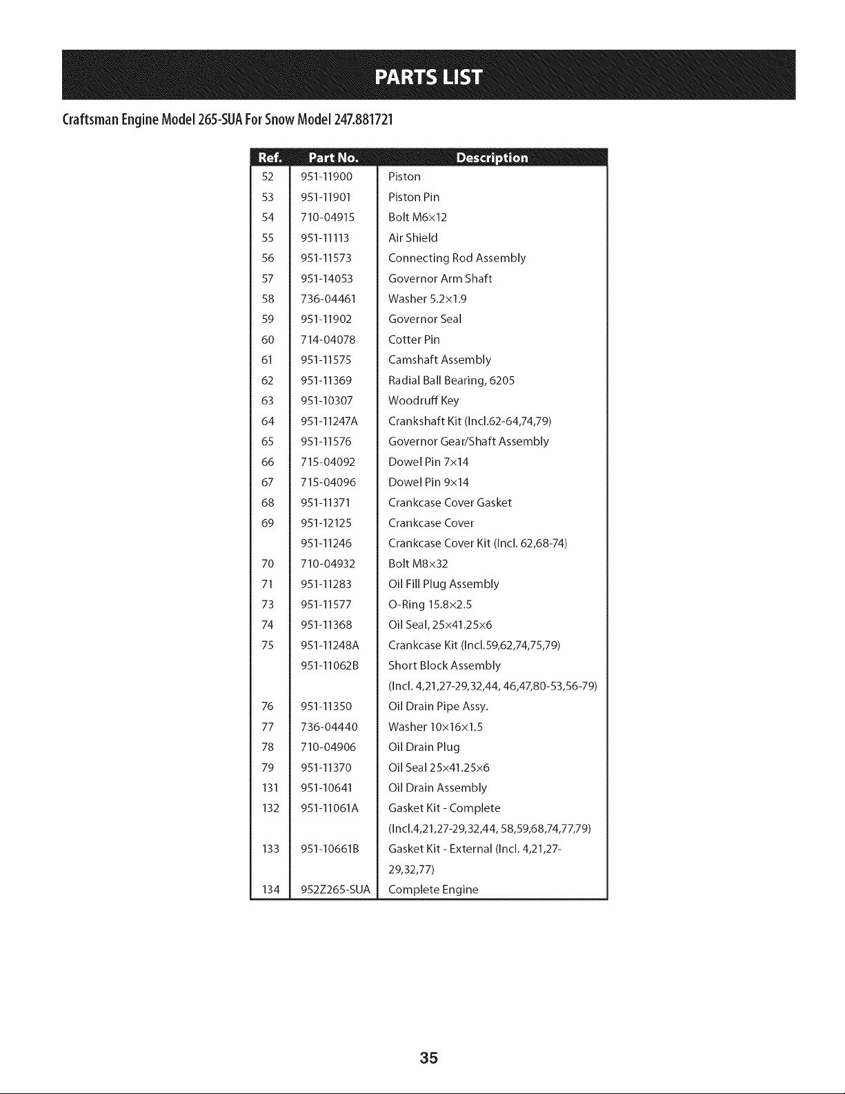
Craftsman EngineModel 265-SUAForSnowModel 247.881721
52
53
54
55
56
57
58
59
60
61
62
63
64
65
66
67
68
69
70
71
73
74
75
76
77
78
79
131
132
133
134
951-11900
951-11901
710-04915
951-11113
951-11573
951-14053
736-04461
951-11902
714-04078
951-11575
951-11369
951-10307
951-11247A
951-11576
715-04092
715-04096
951-11371
951-12125
951-11246
710-04932
951-11283
951-11577
951-11368
951-11248A
951-11062B
951-11350
736-04440
710-04906
951-11370
951-10641
951-11061A
951-10661B
952Z265-SUA
D - ® 0
Piston
Piston Pin
Bolt M6x12
Air Shield
Connecting Rod Assembly
Governor Arm Shaft
Washer 5.2xl.9
Governor Seal
Cotter Pin
Camshaft Assembly
Radial Ball Bearing, 6205
Woodruff Key
Crankshaft Kit (Incl.62-64,74,79)
Governor Gear/Shaft Assembly
Dowel Pin 7x14
Dowel Pin 9x14
Crankcase Cover Gasket
Crankcase Cover
Crankcase Cover Kit (Incl. 62,68-74)
Bolt M8x32
Oil Fill Plug Assembly
O-Ring 15.8x2.5
Oil Seal, 25x41.25x6
Crankcase Kit (Incl.59,62,74,75,79)
Short Block Assembly
(Incl. 4,21,27-29,32,44, 46,47,80-53,56-79)
Oil Drain Pipe Assy.
Washer 10x16x1.5
Oil Drain Plug
Oil Seal 25x41.25x6
Oil Drain Assembly
Gasket Kit - Complete
(In cl.4,21,27-29,32,44, 58,59,68,74,77,79)
Gasket Kit - External (Incl. 4,21,27-
29,32,77)
Complete Engine
35
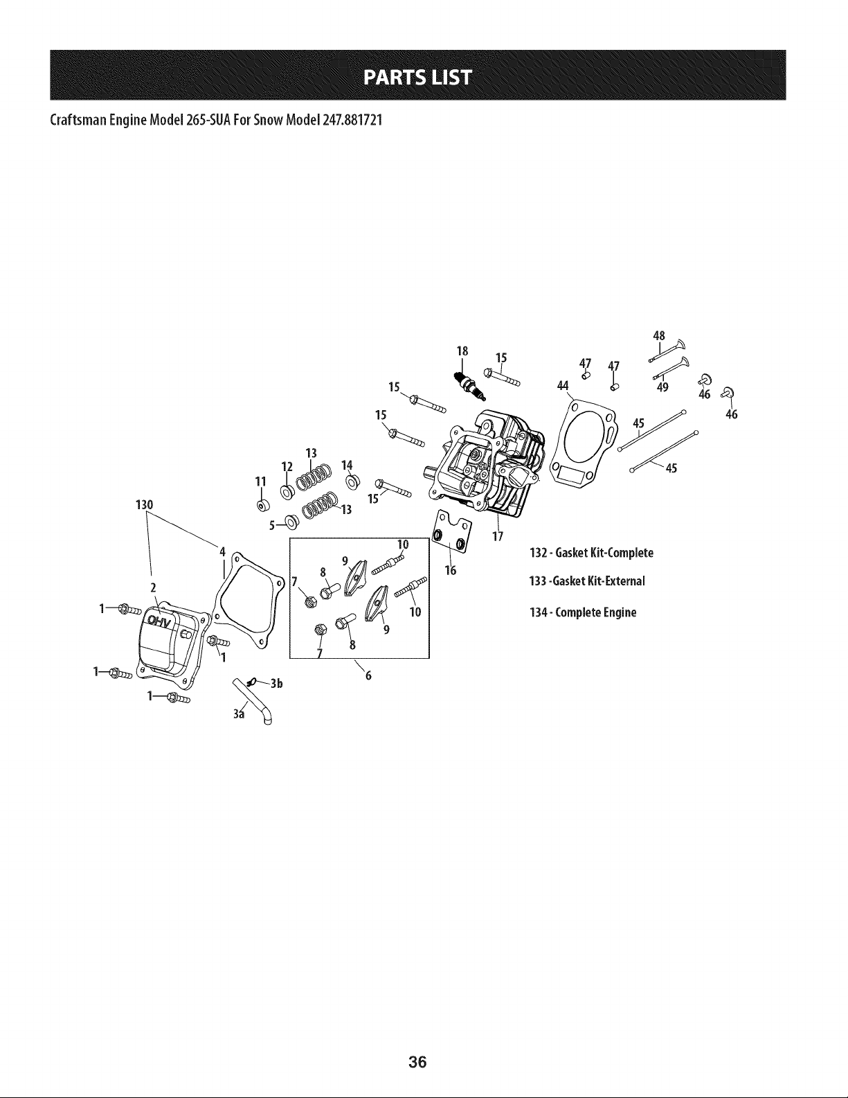
Craftsman EngineModeJ265-SUAFor SnowModeJ247.881721
48
15 44
13
10
\6
17
132- GasketKit-CompJete
133-GasketKit-External
134- CompleteEngine
36
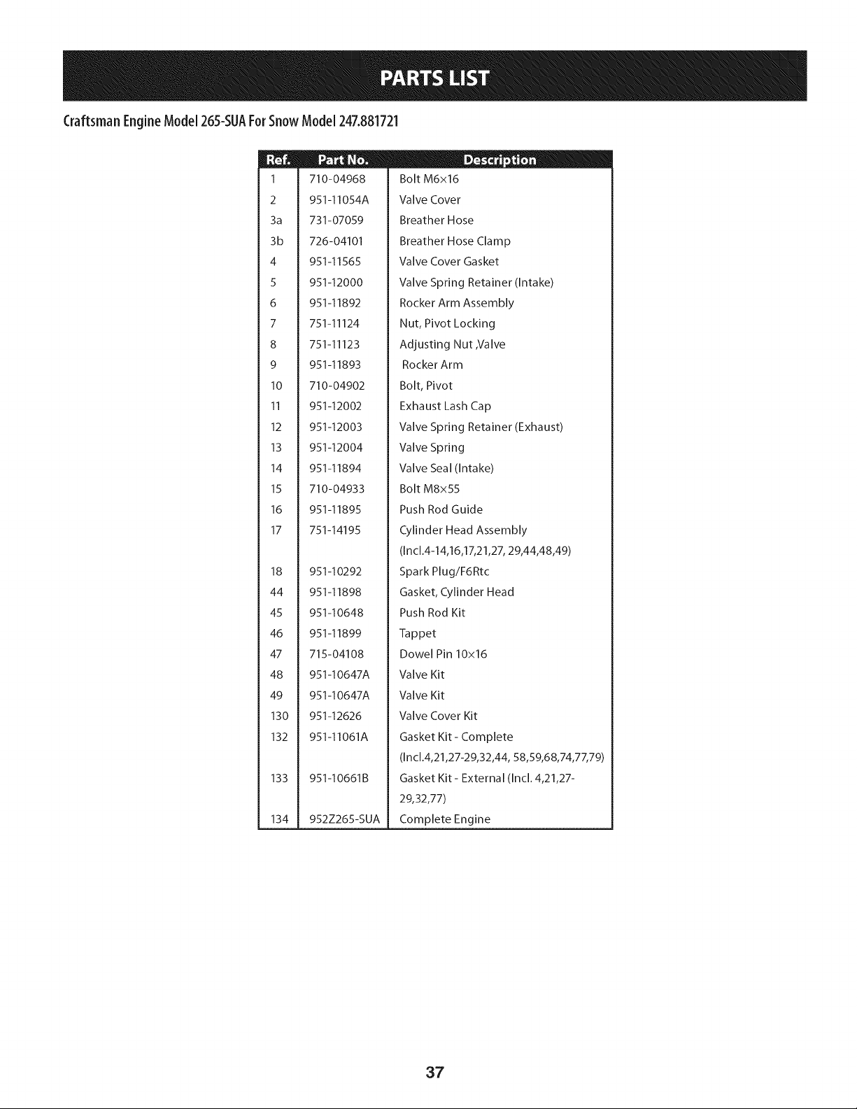
Craftsman EngineModel 265-SUAForSnowModel 247.881721
1
2
3a
3b
4
5
6
7
8
9
10
11
12
13
14
15
16
17
18
44
45
46
47
48
49
130
132
133
134
710-04968
951-11054A
731-07059
726-04101
951-11565
951-12000
951-11892
751-11124
751-11123
951-11893
710-04902
951-12002
951-12003
951-12004
951-11894
710-04933
951-11895
751-14195
951-10292
951-11898
951-10648
951-11899
715-04108
951-10647A
951-10647A
951-12626
951-11061A
951-10661B
952Z265-SUA
D - o o
Bolt M6x16
Valve Cover
Breather Hose
Breather Hose Clamp
Valve Cover Gasket
Valve Spring Retainer (Intake)
Rocker Arm Assembly
Nut, Pivot Locking
Adjusting Nut ,Valve
Rocker Arm
Bolt, Pivot
Exhaust Lash Cap
Valve Spring Retainer (Exhaust)
Valve Spring
Valve Seal (Intake)
Bolt M8x55
Push Rod Guide
Cylinder Head Assembly
(In cl.4-14,16,17,21,27, 29,44,48,49)
Spark Plug/F6Rtc
Gasket, Cylinder Head
Push Rod Kit
Tappet
Dowel Pin 10x16
Valve Kit
Valve Kit
Valve Cover Kit
Gasket Kit - Complete
(In cl.4,21,27-29,32,44, 58,59,68,74,77,79)
Gasket Kit - External (Incl. 4,21,27-
29,32,77)
Complete Engine
37
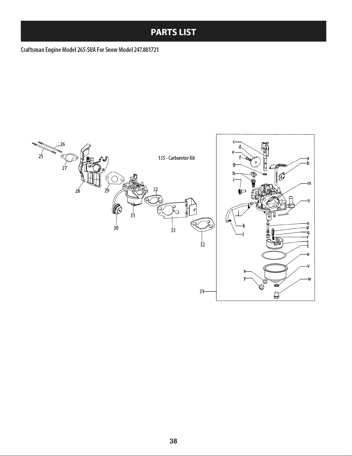
CraftsmanEngineModel265-SUAFor SnowModel 247.881721
27
28
3O
135- CarburetorKit
31_
w
38
Craftsman EngineModel 265-SUAForSnowModel 247.881721
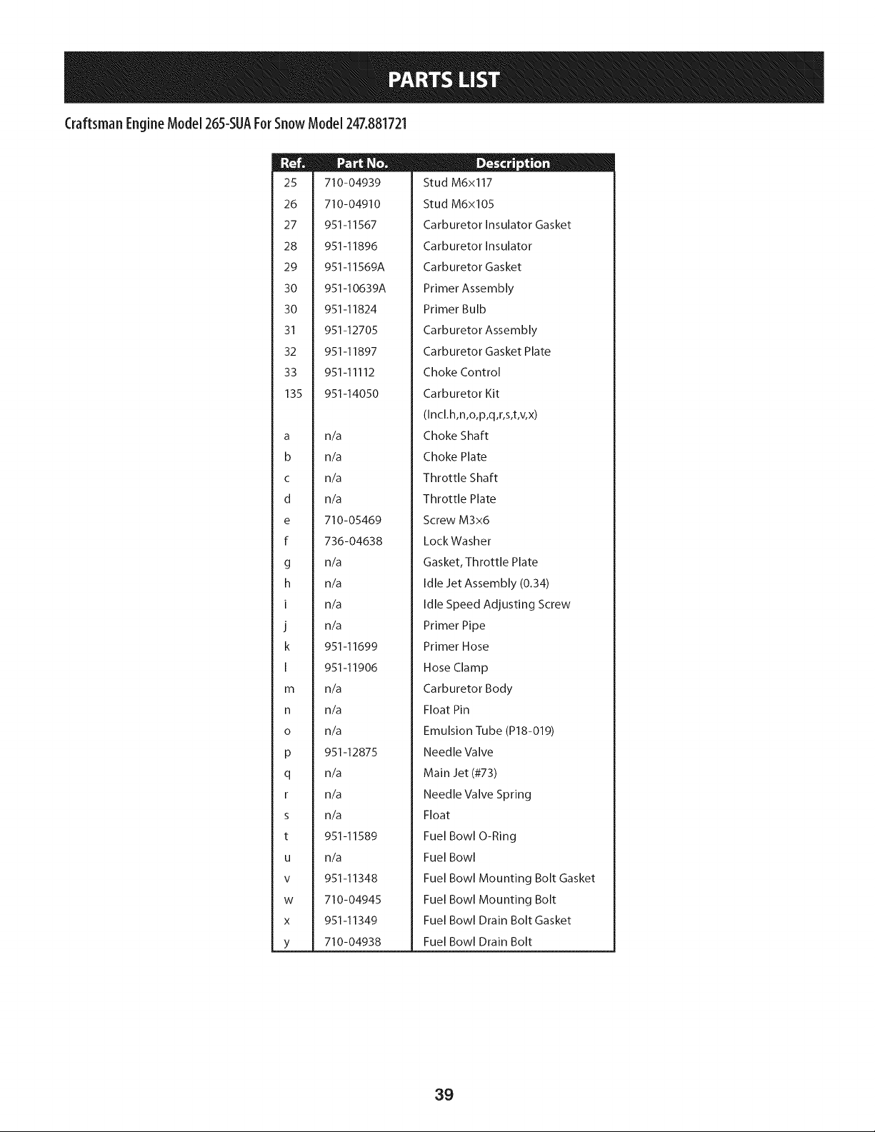
25
26
27
28
29
30
30
31
32
33
135
a
b
C
d
e
f
g
h
I
J
k
I
m
n
0
P
q
r
s
t
U
V
W
X
Y
710-04939
710-04910
951-11567
951-11896
951-11569A
951-10639A
951-11824
951-12705
951-11897
951-11112
951-14050
n/a
n/a
n/a
n/a
710-05469
736-04638
n/a
n/a
n/a
n/a
951-11699
951-11906
n/a
n/a
n/a
951-12875
n/a
n/a
n/a
951-11589
n/a
951-11348
710-04945
951-11349
710-04938
D _ o 0
Stud M6x117
Stud M6x105
Carburetor Insulator Gasket
Carburetor Insulator
Carburetor Gasket
Primer Assembly
Primer Bulb
Ca rburetor Assembly
Carburetor Gasket Plate
Choke Control
Carburetor Kit
(Incl.h,n,o,p,q,r,s,t,v,x)
Choke Shaft
Choke Plate
Throttle Shaft
Throttle Plate
Screw M3x6
LockWasher
Gasket, Throttle Plate
Idle Jet Assembly (0.34)
Idle Speed Adjusting Screw
Primer Pipe
Primer Hose
Hose Clamp
Carburetor Body
Float Pin
Emulsion Tube (P18-019)
Needle Valve
Main Jet (#73)
Needle Valve Spring
Float
Fuel Bowl O-Ring
Fuel Bowl
Fuel Bowl Mounting Bolt Gasket
Fuel Bowl Mounting Bolt
Fuel Bowl Drain Bolt Gasket
Fuel Bowl Drain Bolt
39
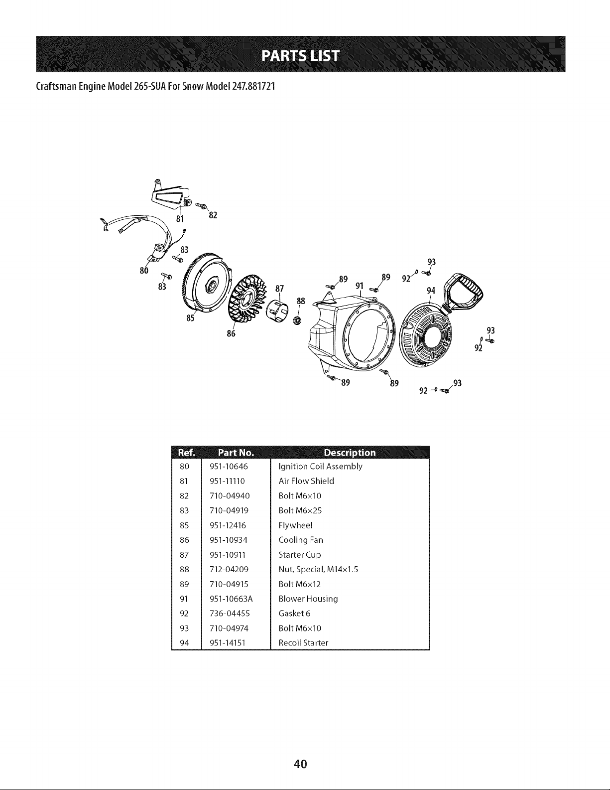
Craftsman EngineModel 265-SUAFor SnowModel 247.881721
82
8O
81
82
83
85
86
87
88
89
91
92
93
94
951-10646
951-11110
710-04940
710-04919
951-12416
951-10934
951-10911
712-04209
710-04915
951-10663A
736-04455
710-04974
951-14151
D - o o
Ignition Coil Assembly
Air Flow Shield
Bolt M6xlO
Bolt M6x25
Flywheel
Cooling Fan
Starter Cup
Nut, Special, M14x1.5
Bolt M6x12
Blower Housing
Gasket 6
Bolt M6xlO
Recoil Starter
4O
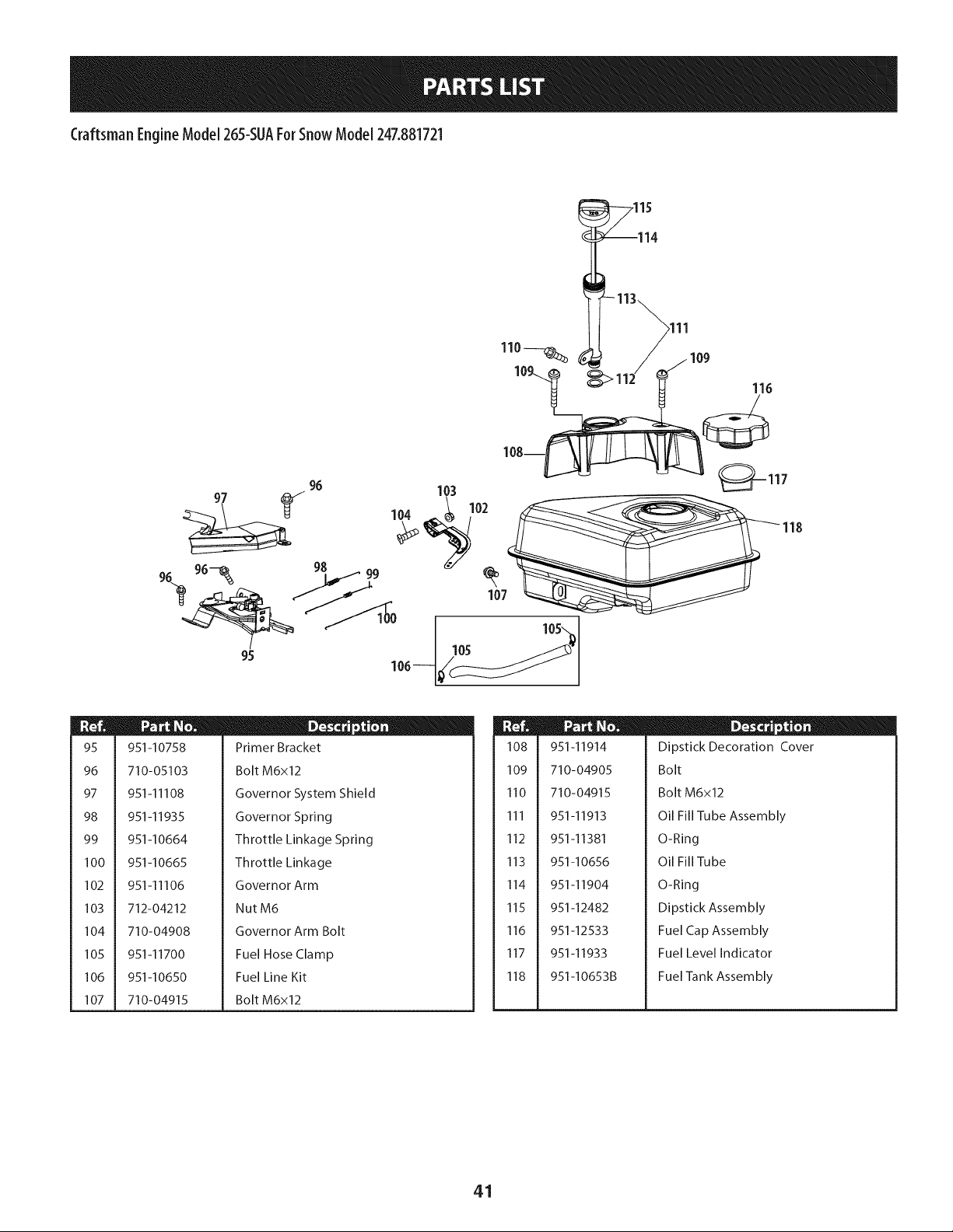
Craftsman EngineModel 265-SUAForSnowModel 247.881721
_115
116
96 103 _117
96- 9s 99
107
95
105
m
95
96
97
98
99
100
102
103
104
105
106
107
951-10758
710-05103
951-11108
951-11935
951-10664
951-10665
951-11106
712-04212
710-04908
951-11700
951-10650
710-04915
D _ o o
Primer Bracket
Bolt M6x12
Governor System Shield
Governor Spring
Throttle Linkage Spring
Throttle Linkage
Governor Arm
NutM6
Governor Arm Bolt
Fuel Hose Clamp
Fuel Line Kit
Bolt M6x12
108
109
110
111
112
113
114
115
116
117
118
951-11914
710-04905
710-04915
951-11913
951-11381
951-10656
951-11904
951-12482
951-12533
951-11933
951-10653B
D _ o o
Dipstick Decoration Cover
Bolt
Bolt M6x12
Oil Fill Tube Assembly
O-Ring
Oil Fill Tube
O-Ring
Dipstick Assembly
Fuel Cap Assembly
Fuel Level Indicator
Fuel Tank Assembly
41
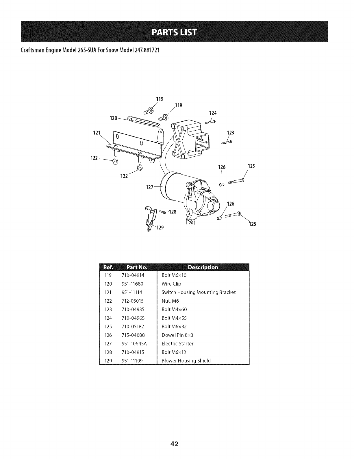
Craftsman EngineModel 265-SUAFor SnowModel 247.881721
121
119
120
123
122_
122
_i _128
29
m
119
120
121
122
123
124
125
126
127
128
129
710-04914
951-11680
951-11114
712-05015
710-04935
710-04965
710-05182
715-04088
951-I0645A
710-04915
951-11109
D - o e
Bolt M6xlO
Wire Clip
Switch Housing Mounting Bracket
Nut, M6
Bolt M4x60
Bolt M4x55
Bolt M6x32
Dowel Pin 8x8
Electric Starter
Bolt M6x12
Blower Housing Shield
42
Craftsman SnowThrowerModel247.881721
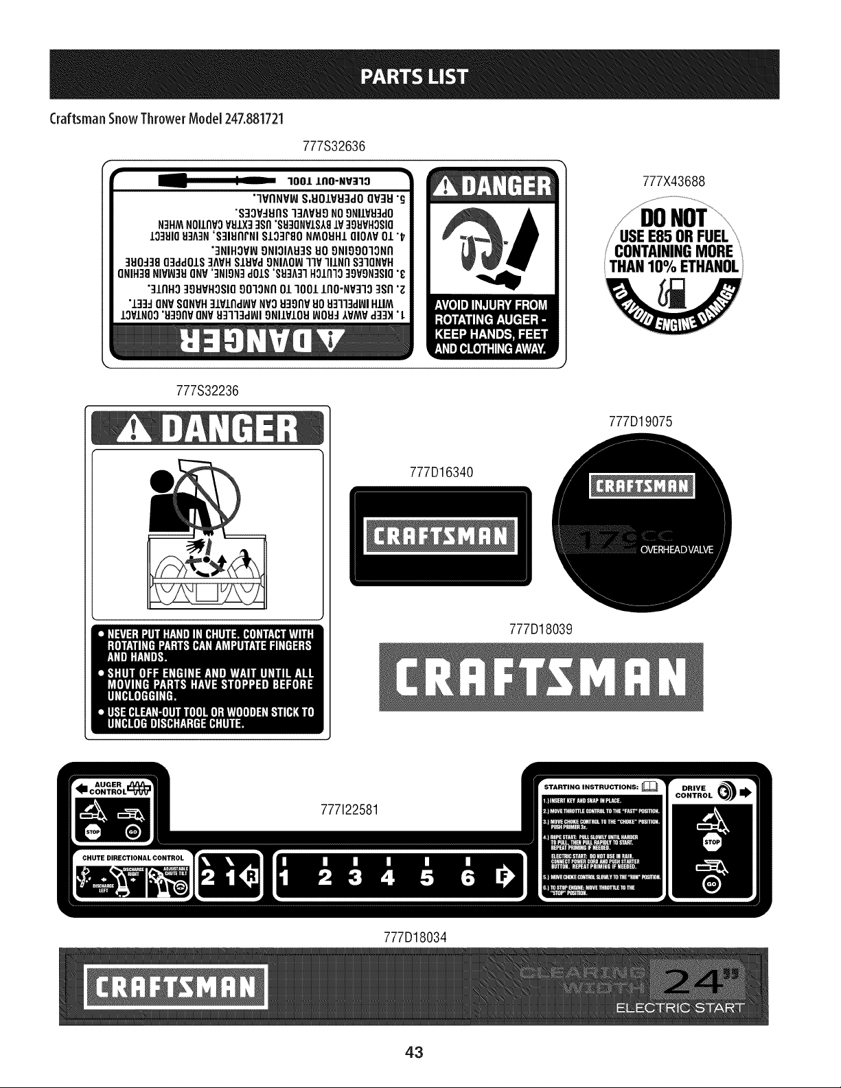
777S32636
1001 JLAO-NV:r'IO
"'IVANV_S,EIO/VEI3dOOV3EI"_;
"S3OV:IEIrlSI3AVEI9NO9NIIVEFIdO
N3HMNOIlrlV3VEIIX33Srl"SEI3ONVISA8IV 39EIVHOSIO
10:1810EI:IA:IN'S31EIIlrNI$103F80NMOEIHLOIOM01 "1;'
"3NIHOVIN9NIOIAEI3S1409NI99013NII
3E10-13803ddOIS3MH SIEIVd9NIAO_]IV ]llNfl S31QNVH
ONIH:I8NIVW:IEIONV':INION3dOIS'SEFIA:rlHOlI1]O3OVON:ISIO"t;
"]lrlHO39EIVHOSIOO01ONrlOl 1001 IIIO-NV3]O3Srl"Z
"133:JONVSONVH31VIIldlt,,IVNVOEI3OrlV80 EI3"1"13dl_lHIIM
IOVINO3"EI391lVONVEI3"II3dWI9NIIVIOEIWOEI-IAVMVd33H"I.
777X43688
E85 ORFUEL
CONTAININGMORE
THAN10% ETHANOL
777S32236
777D19075
777D16340
777D18039
777122581
777D18034
43
FEDERALand/or CALIFORNIAEMISSIONCONTROLWARRANTYSTATEMENT
YOURWARRANTYRIGHTSANDOBLIGATIONS
MTD Consumer Group Inc, the United States Environmental Protection Agency (EPA), and for those products certified for sale in the state of
California, the California Air Resources Board (CARB) are pleased to explain the emission (evaporative and/or exhaust) control system (ECS)
warranty on your 2013 and later small off-road spark-ignited engine and equipment (outdoor equipment engine). In California, new outdoor
equipment engines must be designed, built and equipped to meet the State's stringent anti-smog standards (in other states, outdoor
equipment engines must be designed, built, and equipped to meet the U.S. EPA small off-road spark ignition engine regulations). MTD
Consumer Group Inc must warrant the ECSon your outdoor equipment engine for the period of time listed below, provided there has been no
abuse, neglect, or improper maintenance of the outdoor equipment engine.
Your ECS may include parts such as the carburetor, fuel-injection system, ignition system, catalytic converter, fuel tanks, fuel lines, fuel caps,
valves, canisters, filters, vapor hoses, clamps, connectors, and other associated emission-related components.
Where a warrantable condition exists, MTD Consumer Group Inc will repair your outdoor equipment engine at no cost to you including
diagnosis, parts, and labor.
MANUFACTURER'SWARRANTYCOVERAGE:
This emission control system is warranted for two years. If any emission-related part on your outdoor equipment engine is defective, the
part will be repaired or replaced by MTD Consumer Group Inc. In the event that a component is covered for longer than two years by the
Manufacturer's equipment warranty, the longer coverage period will apply.
/
OWNERSWARRANTYRESPONSIBILITIES:
As the outdoor equipment engine owner, you are responsible for performance of the required maintenance listed in your owner's manual. MTD
Consumer Group Inc recommends that you retain all receipts covering maintenance on your outdoor equipment engine, but MTD Consumer
Group Inc cannot deny warranty solely for the lack of receipts.
As the outdoor equipment engine owner, you should however be aware that MTD Consumer Group Inc may deny you warranty coverage if
your outdoor equipment engine or a part has failed due to abuse, neglect, improper maintenance, or unapproved modifications.
You are responsible for presenting your outdoor equipment engine to MTD Consumer Group Inc's distribution center or service center as soon
as the problem exists. The warranty repairs should be completed in a reasonable amount of time, not to exceed 30 days. If you have a question
regarding your warranty coverage, you should contact the MTD Consumer Group Inc Service Department at 1-800-800-7310 or at
http://su pport.mtd prod ucts.com.
GENERALEMISSIONSWARRANTYCOVERAGE:
MTD Consumer Group Inc warrants to the ultimate purchaser and each subsequent purchaser that the outdoor equipment engine is: (1)
designed, built, and equipped so as to conform with all applicable regulations; and (2) free from defects in materials and workmanship that
cause the failure of a warranted part for a period of two years.
The warranty period begins on the date the outdoor equipment engine is delivered to an ultimate purchaser or first placed into service.
Subject to certain conditions and exclusions as stated below, the warranty on emission-related parts is as follows:
1. Any warranted part that is not scheduled for replacement as required maintenance in the written instructions supplied is warranted for
the warranty period stated above. If the part fails during the period of warranty coverage, the part will be repaired or replaced by MTD
Consumer Group Inc according to subsection (4) below. Any such part repaired or replaced under warranty will be warranted for the
remainder of the period.
2. Any warranted part that is scheduled only for regular inspection in the written instructions supplied is warranted for the warranty period
stated above. Any such part repaired or replaced under warranty will be warranted for the remaining warranty period.
3. Any warranted part that is scheduled for replacement as required maintenance in the written instructions supplied is warranted for the
period of time before the first scheduled replacement date for that part. If the part fails before the first scheduled replacement, the part
will be repaired or replaced by MTD Consumer Group Inc according to subsection (4) below. Any such part repaired or replaced under
warranty will be warranted for the remainder of the period prior to the first scheduled replacement point for the part.
Repair or replacement of any warranted part under the warranty provisions herein must be performed at a warranty station at no charge
to the owner.
4.
5. Notwithstanding the provisions herein, warranty services or repairs will be provided at all of our distribution centers that are franchised to
service the subject engines or equipment.
6. The outdoor equipment engine owner will not be charged for diagnostic labor that is directly associated with diagnosis of a defective,
emission-related warranted part, provided that such diagnostic work is performed at a warranty station.
7. MTD Consumer Group Inc is liable for damages to other engine or equipment components proximately caused by a failure under
warranty of any warranted part.
8. Throughout the off-road engine and equipment warranty period stated above, MTD Consumer Group Inc will maintain a supply of
warranted parts sufficient to meet the expected demand for such parts.
9. Any replacement part may be used in the performance of any warranty maintenance or repairs and must be provided without charge to
the owner. Such use will not reduce the warranty obligations of MTD Consumer Group Inc.
10. Add-onormodifiedpartsthatarenotexemptedbytheAirResourcesBoardmaynotbeused.Theuseofanynon-exemptedadd-onor
modifiedpartsbytheultimatepurchaserwillbegroundsfordisallowingawarrantyclaims.MTDConsumerGroupIncwillnotbeliableto
warrantfailuresofwarrantedpartscausedbytheuseofanon-exemptedadd-onormodifiedpart.
WARRANTEDPARTS:
The repair or replacement of any warranted part otherwise eligible for warranty coverage may be excluded from such warranty coverage if
MTD Consumer Group Inc demonstrates that the outdoor equipment engine has been abused, neglected, or improperly maintained, and that
such abuse, neglect, or improper maintenance was the direct cause of the need for repair or replacement of the part. That notwithstanding,
any adjustment of a component that has a factory installed, and properly operating, adjustment limiting device is still eligible for warranty
coverage. Further, the coverage under this warranty extends only to parts that were present on the off-road engine and equipment purchased.
The following emission warranty parts are covered (if applicable):
1. Fuel Metering System
Cold start enrichment system (soft choke)
Carburetor and internal parts (or fuel injection system)
Fuel pump
Fuel tank
2. Air Induction System
Air cleaner
Intake manifold
3. Ignition System
Spark plug(s)
Magneto ignition system
4. Exhaust System
Catalytic converter
SAI (Reed valve)
5. Miscellaneous Items Used in Above System
Vacuum, temperature, position, time sensitive valves and switches
Connectors and assemblies
6. Evaporative Control
Fuel hose
Fuel hose clamps
Tethered fuel cap
Carbon canister
Vapor lines
050790 Rev.A
Congratulationsonmakingasmartpurchase.YournewCraftsman®productisdesignedandmanufacturedforyearsof
dependableoperation.Butlikeall products,it mayrequirerepairfromtime to time.That'swhenhavinga RepairProtection
Agreementcansaveyoumoneyandaggravation.
Here'swhat the Repair ProtectionAgreement_ includes:
[] Expertservice byour10,000professionalrepairspecialists
[] Unlimitedserviceand nocharge forpartsandlaboronallcoveredrepairs
[] Productreplacementupto $1500ifyourcoveredproductcan'tbefixed
[] Discountof 25%from regularpriceof serviceandrelatedinstalledpartsnot coveredbythe agreement;also,25%off
regularpriceof preventivemaintenancecheck
[] Fasthelp by phone- wecallit RapidResolution- phonesupportfromaSearsrepresentative.Thinkof usasa"talking
owner'smanual."
Onceyoupurchasethe RepairProtectionAgreement,a simplephonecallisallthat it takesforyouto scheduleservice.You
cancallanytimedayornight,orscheduleaserviceappointmentonline.
TheRepairProtectionAgreementisa risk-freepurchase.If youcancelfor anyreasonduringthe productwarrantyperiod,
wewill provideafull refund.Or,a proratedrefundanytimeafterthe productwarrantyperiodexpires.PurchaseyourRepair
ProtectionAgreementtoday!
Somelimitations and exclusionsapply. Forpricesand additional informationin the U.S.A.call 1-800-827-6655.
_Coveragein Canadavarieson someitems. Forfull detailscall SearsCanadaat 1-800-361-6665.
SearsInstallationService
ForSearsprofessionalinstallationof homeappliances,garagedooropeners,waterheaters,andothermajorhomeitems,in
the U.S.A.orCanadacall1-800-4-MY-HOME®.
46
Declaraci6n de garantia ....................... P_gina 47
Pr_cticas operaci6n seguras ................... P_gina 48
Montaje ...................................... P_gina 52
Operaci6n .................................... P_gina 56
Servicio y Mantenimiento ..................... P_gina 60
Almacenamiento fuera de temporada ......... P_gina 68
Solucidn de problemas ........................ P_gina 70
Acuerdo de proteccidn para reparaciones ...... P_gina 74
Lista de piezas ................................ P_gina 26
Numero de servicio .................. Cubierta posterior
GARANTIACOMPLETACRAFTSMANPORDOSANOS
PORDOSANOSa partirde lafechadela compra,esteproductoest_garantizadopotdefectosen losmaterialesy lamanodeobra.
Losproductosdefectuososser_nreparadossincostooreemplazadossincostosilareparaci6nnoest_disponible.
Paraobtenerinformaci6nsobreelalcancedela garantiay solicitarla reparaci6noelreemplazo,visiteel sitioWeb:www.craftsman.com
EstagarantiacubreONICAMENTElosdefectosenlosmaterialesyen lamanodeobra.EstagarantiaNOcubre:
• Elementosnorenovablesquepuedendesgastarsepotel usonormal,duranteelplazodela garantia,incluyendoentreotros,lasbarrenas,laspaletasde
lasbarrenas,loscortadoresdedesplazamiento,laszapatasantideslizantes,laplacaderaspado,lospasadoresdecuchilla,la bujia,el filtro deaire,las
correasy elfiltro deaceite.
• Serviciosdemantenimientoest_ndar,cambiosdeaceiteo afinaci6n.
• Cambiodeneum_ticosoreparacionespot pinchadurasconobjetosexternoscomoclavos,espinas,toconesovidrios.
• Reemplazooreparaci6ndeneum_ticoso ruedascomoresultadodeldesgastenormal,un accidente,ofuncionamiento
omantenimientoincorrectos.
• Reparacionesrequeridascomoresultadodel usoinadecuadoporpartedeloperador,incluyendoentreotrosel daEoocasionadoporobjetosque
impactanlam_quinayquetuercenel bastidor,elejedelabarrena,etc.,o debidoa queel motorrueaceleradoenexceso.
• Reparacionesnecesariasdebidoa negligenciadeloperador,incluyendoentreotros,daEosmec_nicoy el_ctricoocasionadopot
unalmacenamientonoapropiado,fallapotel usodeaceitedegradoy/ocantidadnoapropiadosofallapornodarmantenimiento
alequipodeacuerdoconlasinstruccionescontenidasen elmanualdeloperador.
• Limpiezao reparacionesdelmotor(sistemadecombustible)debidasacombustiblequesedeterminaest_contaminadou oxidado(viejo).Engeneral,el
combustibledebeutilizarseen unperiodonomayorde30diasapartirdesuadquisici6n.
• Eldeterioroy desgastenormaldelosacabadosexteriores,o reemplazodela etiquetadelproducto.
LapresentegarantiaseanulasiseutilizaesteproductoalgunavezparaprestarservicioscomercialesosiseIoalquilaa otrapersona.
Estagarantialeotorgaderechoslegalesespecificos,peroustedpodriagozardeotrosderechosenraz6ndesulugarderesidencia.
SearsBrandsManagementCorporation,HoffmanEstates,IL60179
Aceite del motor: 5W-30
Combustible: Gasolina sin plomo
Motor: MTD
© Sears Brands, LLC
Numero de modelo
Numero de serie
Fecha de compra
Registre el numero de modelo, numero de serie y fecha
de compra m_s arriba.
47
Lapresendadeeste simboloindica cluesetrata de instrucciones
importantes de seguridadquesedebenrespetarparaevitar poneren
peligro suseguridadpersonaly/o materialy lade otras personas.Leay siga
todaslasinstruccionesdeestemanualantesde poner enfundonamiento
estam_iguina.SinorespetaestasinstrucdonespodriaprovocarJesiones
personales.Cuandoyeaeste simboJo,ipresteatend6n a laadvertencia!
PROPOSICION 65 DE CALiFORNiA
Elescapedel motor deesteproducto,algunosde suscomponentesy
algunoscomponentesdel vehiculocontieneno liberansustanciasquimicas
queelestado deCaliforniaconsideraquepuedenprodudr c_ncer,defectos
de nadmiento u otros problemasreproductivos.
Estam_iquinarue construida parasetoperadadeacuerdoconlasreglas
de seguridadcontenidaseneste manual.AI igual queconcualquiertipo
de equipo motorizado,undescuidoo errorpot parte deJoperadorpuede
producir lesionesgraves.Estam_iquinaescapazde amputar manosy pies
y de arrojarobjetoscon granfuerza.Deno respetarlasinstrucdonesde
seguridadsiguientessepuedenproducir lesionesgraveso la muerte.
Su responsabilidad--Restrinja el usodeestam_quina motorizada
alas personasquelean,comprendany respetenlasadvertendase
instrucdonesqueaparecenen este manualy enla m_quina.
iGUARDEESTASINSTRUCCIONES!
CAPACITACION
Lea,entiendaycumplatodaslasinstruccionesincluidasenlam_quinay en
losmanualesantesde montarlay utilizarla.Guardeestemanualenunlugar
seguroparaconsultasfuturasy peri6dicas,asicomoparasolicitarrepuestos.
Leael Manualdel 0peradory sigatodaslasadvertenciase instruccionesde
seguridad.Elfracasode hacerasipuedecausarlaheridaseriaal operadory/o
personaspresentes.
Familiaricesecontodosloscontrolesyconelusoadecuadodelosmismos.
Sepac6modetenerlam_quinay desactivarloscontrolesr_pidamente.
Nopermitanuncaquelosnifiosmenoresde 14afiosutilicenestam_quina.
Losnifiosde 14afiosenadelantedebenleery entenderlasinstrucciones
deoperaci6nynormasde seguridadcontenidasen estemanual,y enla
m_quinaydebenserentrenadosy supervisadospot unadulto.
Nuncapermitaquelosadultosoperenestam_quinasinrecibirantesla
instrucci6napropiada.
Losobjetosarrojadosporlam_quinapuedenproducirlesionesgraves.
Planifiqueel patr6nenelquevaair arrojandonieveparaevitarquela
descargade materialserealicehacialoscaminos,losobservadores,etc.
Mantengaa losobservadores,ayudantes,mascotasynifiosporIo menosa
75piesde lam_quinamientraslamismaest_enfuncionamiento.Detengala
m_quinasialguienseacerca.
Seaprecavidoparaevitarpatinarseo caerseespecialmentecuandooperala
m_quinaenreversa.
PREPARATlVOS
Inspecdoneminuaosamenteel_ireadondeutilizar_iel equipo.Saquetodoslos
felpudos,peri6dicos,trineos,tablas,cablesy otrosobjetosextrafiosconlosque
podriatropezaro quepodrianserarrojadosporlabarrena/impulsor.
Panprotegerselosojosutilicesiempreanteojosoantiparrasde seguridad
mientrasoperalam_iquinaomientraslaajustaorepara.Losobjetos
arrojadosquerebotanpuedenproducirlesionesocularesgraves.
Nooperelam_iquinasinlavestimentaadecuadaparaestaral airelibreen
inviemo.Noutilicealhajas,bufandaslargasu otrasprendassueltasque
podrianenredarseen laspartesm6viles.Utiliceun calzadoespecialpara
superficiesresbaladizas.
Useun prolongadory un tomacorrientedetrescablesconconexi6natierra
paratodaslasm_iquinasconmotoresdeencendidoel_ctrico.
Ajustelaalturade lacajadel tomacorrienteparalimpiarlagravao las
superficiesconpiedrastrituradas.
Desengranetodaslaspalancasdecontrolantesdearrancarel motor.
Nuncaintenterealizarajustesmientraselmotorest_ien marchaexceptoen
loscasosespecificamenterecomendadosenel manualdel operador.
Dejequeel motory la m_iquinaseadaptenalatemperaturaexteriorantes
decomenzarasacarlanieve.
48
Manejo seguro de la gasolina
Paraevitarlesionespersonalesodafiosmaterialestengamuchocuidadocuando
trabajecongasolina.Lagasolinaessumamenteinflamabley susvaporespueden
causarexplosiones.Sisederramagasolinaencimaosobrela ropasepuedelesionar
gravementeyaquesepuedeincendiar.L_vesela piely c_mbiesederopade
inmediato.
Utilices61olos redpientesparagasolinaautorizados.
Apaguetodoslosdgarrillos,dgarros,pipasy otrasfuentesdecombusti6n.
Nuncacarguecombustibleen lam_quinaenun espadocerrado.
Nuncasaquelatapadelcombustibleniagreguecombustiblemientrasel
motorest_calienteoen marcha.
Dejequeel motorseenfrieporIomenosdosminutosantesde volvera
cargarcombustible.
NuncaIleneenexcesoeldep6sitodecombustible.Lleneeltanquea no m_s
de1/2pulgadapordebajode labasedel cuellodeIlenadodejandoespado
paraladilatad6ndel combustible.
Vuelvaacolocarlatapadela gasolinay ajOstelabien.
Limpieelcombustiblequesehayaderramadosobreel motory elequipo.
Trasladela m_quinaaotra zona.Espere5minutosantesde encenderel
motor.
Nuncaalmacenelam_quinao elredpientede combustibleenunespado
cerradodondehayafuego,cHspasoluzpiloto(porejemplo,hornos,
calentadoresdeagua,calefactores,secadoresde ropa,etc.).
Dejequelam_quinaseenfrie porIomenos5 minutosantesdeguardarla.
NuncaIlenelosredpientesen elinteriorde unvehkuloocami6no cajade
remolqueconrecuMmientospl_sticos.Coloquesiemprelosredpientesen el
pisoylejosdelvehkuloantesdeIlenarlos.
Siesposible,retireelequipoa gasolinadelcami6noremolquey II_neloen
elsuelo.Siestonoesposible,Ileneel equipoenun remolqueconcontenedor
port_t[I,envezdedesdeunaboquilladispensadoradegasolina.
Mantengalaboquilladispensadoraencontactoconelbordedeldep6sito
decombustibleoconlaaberturadel redpienteentodo momento,hasta
terminarlacarga.Noutilke undispositivodeapertura/derredeboquilla.
FUNCIONAMIENTO
Nopongalasmanoso lospiescercadelaspiezasrotatorias,enlacajadela
barrena/impulsor oenel montajedelcanalde descarga.Hacercontactocon
piezasgiratoriaspuederesultarenlaamputad6nde manoso pies.
Lapalancadecontrolde labarrena/impulsoresundispositivodeseguridad.
Nuncaevitesufundonamiento.Dehacerlolaoperad6nde lam_quinaes
riesgosay puedeocasionarlesiones.
Laspalancasdecontroldebenfundonarbienenambasdkecdonesy
regresarautom_ticamentealaposid6nde desengranecuandoselassuelta.
Nuncaoperela m_quinasifaltaun montajedelcanalo s[elmlsmoest_
daffado.Mantengatodoslosdispositivosdeseguridadensulugaryen
funcionamiento.
Nuncaendendaelmotorenespadoscerradoso enunazonaconpoca
ventilad6n.Elescapedelmotorcontienemon6xidode carbono,un gas
inodoroyletal.
Noutilicelam_quinabajolainfluendadel alcoholo lasdrogas.
Elsilendadory el motorsecalientany puedencausarquemaduras.Nolos
toque.Mantengaalosnifiosalejados.
Seasumamenteprecavidocuandooperelam_quinasobreunasuperfide
congravaocuandolacruce.Mant_ngasealertaporsisepresentanpeligros
ocultosotr_nsito.
Tengacuidadocuandocambiededirecd6nocuandooperelam_quinaen
pendientes.Nouselam_quinaenpendientespronundadas.
Planifiqueelpatr6nenelquevaa irarrojandonieveparaevitarquela
descargade materialseproduzcahadalasventanas,lasparedes,los
autom6viles,etc.y evitarasiposiblesdafiosmaterialeso lesionesproduddas
porlosrebotes.
Nuncadirija [adescargahadalosnifios,losobservadoreso lasmascotasni
dejequenadieseparedelantedela m_quina.
Nosobrecarguelacapaddaddelam_quinatratandodesacarlanievemuy
r_pidamente.
Nuncaopereestam_quinasinbuenavisibilidadoiluminad6n.Siempredebe
estarsegurodequeest_bienafirmadoy sujetandofirmementelasmanijas.
Camine,nuncacorra.
Cortelacorrientealabarrena/impulsorcuandotransportelam_quinao
cuandolamismanoest_enuso.
Nuncaoperela m_quinaaaltaveloddaddedesplazamientosobre
superficiesresbaladizas.Mirehadaabajoy hadaatr_sy tengacuidado
cuandovayamarchaatr_s.
Silam_quinacomenzaraavibrardemaneraanormal,detengaelmotor,
desconecteelcabledelabujiayp6ngalademaneraquehagamasacontra
el motor.Inspecdonelam_quinaminudosamenteparavet siest_dafiada.
Reparetodoslosdafiosantesdeencendery operarlam_quina.
Desengranetodaslaspalancasdecontrolydetengaelmotorantesdedejar
la poski6ndeoperad6n(detr_sde lasmanijas).Esperea quelabarrena/
impulsorsedetengapotcompletoantesdedestaparelmontajedel canalo
realizarajusteseinspecdones.
Nuncapongalasmanosenlasaberturasdedescargao derecolecd6n.Utilke
siemprelaherramientadelimpiezaqueseadjuntaparadestaparlaabertura
de descarga.Nodestapeelmontajedelcanalmientrasel motorest_en
fundonamiento.Antesdedestaparlo,apagueel motorypermanezcadetr_s
de lasmanijashastaquetodaslaspartesm6vilessehayandetenido.
Uses61ounionesy accesoriosaprobadosporel fabricante(porejemplo,
pesasparalasruedas,cadenasparalosneum_ticos,cabinas,etc.).Para
obtenerm_sinformad6nacercadeestostemas,Ilameal 1-800-469-4663.
49
Paraencenderel motor,jaiedelacuerdalentamentehastaquesienta
resistenda,luegojaler_pidamente.Elreplieguer_pidodelacuerdade
arranque(tensi6nde retroceso)lejalar_la manoy elbrazohadaelmotor
m_sr_pidodeIoqueustedpuedesoltar.Elresultadopuedenserhuesos
rotos,fracturas,hematomaso esguinces.
Sisepresentansituacionesquenoest_nprevistasenestemanual,sea
cuidadosoy useelsentidocomfin.
Parapedirrepuestososerviciohorarioparaesteproducto,Namea1-800-
469-4663.
MANTENIMIENTO Y ALMACENAMIENTO
Nuncaalterelosdispositivosde seguridad.Controleperi6dicamenteque
fundonencorrectamente.Remftasealasseccionesdemantenimientoy
ajustedeestemanual.
AntesdereaNzarlaNmpieza,repararo revisarlam_quina,desengrane
todaslaspalancasdecontrolydetengaelmotor.Espereaquelabarrena/
impulsorsedetengaporcompleto.Desconecteelcabledelabujfayp6ngalo
haciendomasacontraelmotorparaevitarqueseenciendaaccidentalmente.
Controlefrecuentementequetodoslos pernosy tornillosest#nbien
ajustadosparacomprobarquelam_quinaseencuentraen condidones
segurasdefuncionamiento.Adem_s,hagaunainspecci6nvisualdela
m_quinaparaverificarsiest_dafrada.
Nocambielaconfigurad6ndel reguladordel motorniaceleredemasiado
elmismo.Elreguladordel motorcontrolalaveloddadm_ximasegurade
funcionamientodel motor.
Lasplacasde raspadoy laszapatasantideslizantesqueseusanconla
m_quinaquitanievesedesgastany sedafran.Paraprotegersuseguridad,
verifiquefrecuentementetodosloscomponentesy reempl_celoss61ocon
partesdelosfabricantesdeequiposoriginales(OEM).iEIusode piezasque
nocumplenconlasespeciflcadonesdelequipooriginalpuederesultaren
rendimientoinadecuadoadem_sdeponerenriesgolaseguridad!
Reviselaspalancasdecontrolperi6dicamenteparaverificarqueengraneny
desengranenadecuadamenteyajtistelossi esnecesario.Consultelasecd6n
deajustesde estemanualdeloperadorparaobtenerinstrucciones.
Mantengaoreemplacelasetiquetasdeseguridadeinstruccionessegtinsea
necesario.
Respetelasnormasreferentesaladisposici6ncorrectay las
reglamentacionessobregasolina,aceite,etc.paraprotegerel medio
ambiente.
Antesdealmacenarlam_quinaenci@ndalaunosminutosparasacarlanieve
quehayaquedadoen lamismay paraevitarasfquesecongelelabarrena/
impulsor.
SegunlaComisi6nde SeguridaddeProductosparaelConsumidordelos
EstadosUnidos(CPSC)y laAgenciadeProtecci6nAmbientaldelosEstados
Unidos(EPA),esteproductotJeneunavidafitil mediadesiete(7)afros,6
60 horasdefuncionamiento.AI finalizarlavidafitil media,adquierauna
m_quinanuevaohagainspeccionaranualmente6staporundistribuidorde
servicioautorizadoparacerciorarsedequetodoslossistemasmec_nicosy de
seguridadfuncionancorrectamentey notienenexcesivodesgaste.SinoIo
hate,puedenproducirseaccidentes,lesionesomuerte
Nuncaalmacenela m_quinaoel recipientedecombustibleen unespacio
cerradodondehayafuego,chispaso luzpilotocomoporejemplo,
calentadoresdeagua,hornos,secadoresderopa,etc.
Consultesiempreelmanualdeloperadorparaobtenerinstrucciones
adecuadasparaelalmacenamientofueradetemporadaVerifique
frecuentementelaIfneadecombustible,eltanque,eltap6n,y losaccesorios
buscandorajaduraso p6rdidas.Reemplacedesernecesario.
Nod6arranqueal motorsi noest_labujfadeencendido.
NO MODIFIQUE EL MOTOR
Paraevitarlesionesgraveso lamuerte,no modifiqueel motorbajoninguna
circunstancia.SIcambialaconfiguraci6ndelreguladorelmotorpuede
descontrolarsey operaravelocidadesinseguras.Nuncacambielaconfiguraci6nde
f_bricadel reguladordelmotor.
AVlSO REFERIDO A EMISIONES
Losmotoresqueest_ncertificadosycumplenconlasregulacionesdeemisiones
federalesEPAy de CaliforniaparaSORE(Equipospequefrostodoterreno)est_n
certificadosparaoperarcongasoNnacomtinsinplomoypuedenincluirlos
siguientessistemasdecontrolde emisiones:Modificaci6ndemotor(EM)y
catalizadordetresvfas(TWC)siest_nequipadosdeesamanera.
GUARDACHISPAS
Estam_quinaest_equipadacon un motor de combusti6ninternayno
debeset utilizadaen o cercade un terreno agrestecubierto potbosque,
maiezaso hierbaexceptosi el sistemade escapedel motorest_ equipado
conun amortiguador dechispasquecumpla conlasleyeslocaleso
estatalescorrespondientes,en casodehaberlas.
Siseutilizaun amortiguadorde chispaseloperadorIodebemanteneren
condicionesde usoadecuadas.Enel EstadodeCalifornialasmedidasanteriormente
mendonadassonexigidasporley(Artkulo 4442delC6digodeRecursosPtiblicos
de California).Esposiblequeexistanleyessimilaresenotrosestados.Lasleyes
federalesseaplicanen territoriosfederales.
Puedeconseguirelamortiguadordechispasparael silendadoratravdsdesu
distribuidorautorizadode motoreso ponidndoseencontactoconel departamento
de servicios.
5O
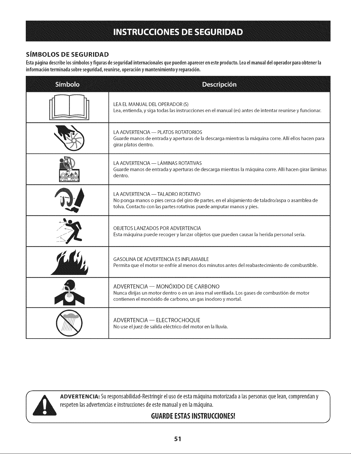
S|MBOLOSDESEGURIDAD
Esta p_gina describe lossimbolosy figuras de seguridad internacionales que pueden aparecer en este producto. Lea el manual del operador para obtener la
informaci6n terminada sobre seguridad, reunirse, operaci6n y mantenimiento y reparad6n.
LEA EL MANUAL DEL OPERADOR (S)
Lea, entienda,y siga todas las instrucciones en el manual (es) antes de intentar reunirse y funcionar.
LA ADVERTENCIA -- PLATOS ROTATORIOS
Guarde manos de entrada y aperturas de la descarga mientras la m_quina corre. Alli ellos hacen para
girar platos dentro.
LA ADVERTENCIA -- LAMINAS ROTATIVAS
Guarde manos de entrada y aperturas de descarga mientras la m_quina corre. Alli hacen girar I_minas
dentro.
LA ADVERTENCIA -- TALADRO ROTATIVO
No ponga manos o pies cerca del giro de partes, en el alojamiento de taladro/aspa o asamblea de
tolva. Contacto con las partes rotativas puede amputar manos y pies.
OBJETOS LANZADOS POR ADVERTENClA
Esta m_quina puede recoger y lanzar objetos que pueden causar la herida personal seria.
GASOLINA DE ADVERTENClA ES INFLAMABLE
Permita que el motor se enfrie al menos dos minutos antes del reabastecimiento de combustible.
ADVERTENCIA -- MONOXIDO DE CARBONO
Nunca dirijas un motor dentro o en un _rea mal ventilada. Los gases de combusti6n de motor
contienen el mon6xido de carbono, un gas inodoro y mortal.
ADVERTENCIA- ELECTROCHOQUE
No useel juez de salida el_ctrico del motor en la Iluvia.
ADVERTENCIA: Suresp0nsabilidad-Restdngirel us0de esta m_quinam0t0rizadaa laspersonasqueLean,c0mprendany
respetenlasadvertendase instrucd0nesdeestemanualy enlam_quina.
J
GUARDEESTASINSTRUCCIONES!
51
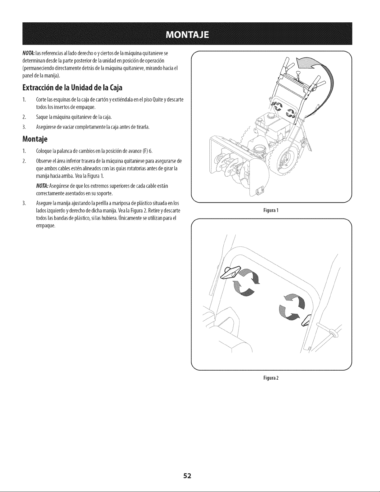
NOTA:lasreferendasal ladoderechoo y ciertosdelam_quinaquitanievese
determinandesdelaparteposteriordela unidaden posici6nde operaci6n
(permaneciendodirectamentedetr_sdelam_quinaquitanieve,mirandohaciael
paneldelamanija).
Extracci6nde ia Unidad de ia Caja
1. Cortelasesquinasde lacajadecart6nyexti_ndalaenel pisoQuitey descarte
todoslosinsertosdeempaque.
2. Saquelam_quinaquitanievedelacaja.
3. Asegtiresede vaciarcompletamentelacajaantesde tirarla.
Montaje
I. Coloquela palancadecambiosenlaposici6ndeavance(F)6.
2. Observeel _reainferiortraserade lam_quinaquitanieveparaasegurarsede
queamboscablesest_nalineadosconlasguiasrotatoriasantesde girarla
manijahadaarriba.Veala FiguraI.
flOT,4:Asegtiresedequelosextremossuperioresdecadacableest_n
correctamenteasentadosensusoporte.
3. Asegurelamanijaajustandolaperillaa mariposade pl_sticosituadaenlos
ladosizquierdoyderechodedichamanija.VealaFigura2. Retirey descarte
todoslasbandasde pl_stico,si lashubiera.Onicamenteseutilizanparael
empaque.
Figura1
/
/
/
/
/
/
\
Figura 2
52
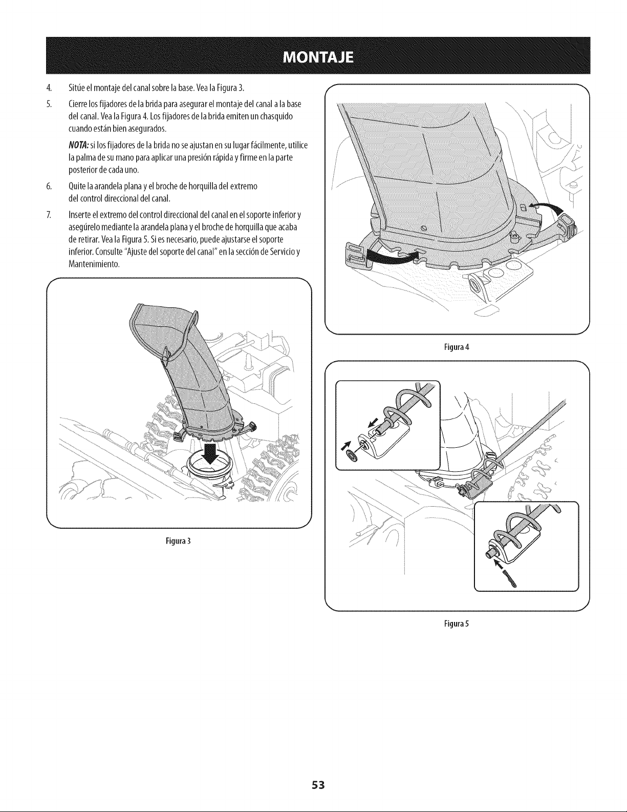
4. Situeelmontajedelcanalsobrelabase.Veala Figura3.
5. Cierrelosfijadoresde labridaparaasegurarelmontajedelcanala labase
delcanal.VealaFigura4. Losfijadoresde labridaemitenun chasquido
cuandoest_nbienasegurados.
#OTII:si losfijadoresde labridano seajustanensulugarf_cilmente,utilice
lapalmadesumanoparaaplicarunapresidnr_piday firmeen laparte
posteriorde cadauno.
6. Quitelaarandelaplanay elbrochedehorquilladelextremo
delcontroldireccionaldelcanal.
Inserteelextremodelcontroldirectionaldelcanalenelsoporteinferiory
asegLirelomedJantelaarandelaplanay elbrochedehorquJllaqueacaba
deretirar.VealaFigura5.Siesnecesario,puedeajustarseelsoporte
inferior.Consulte"Ajustedelsoportedelcanal"en lasecci6nde Servicioy
Mantenlmlento.
f
J
Figura4
f
,,. j
Figura3
J
Figura5
53
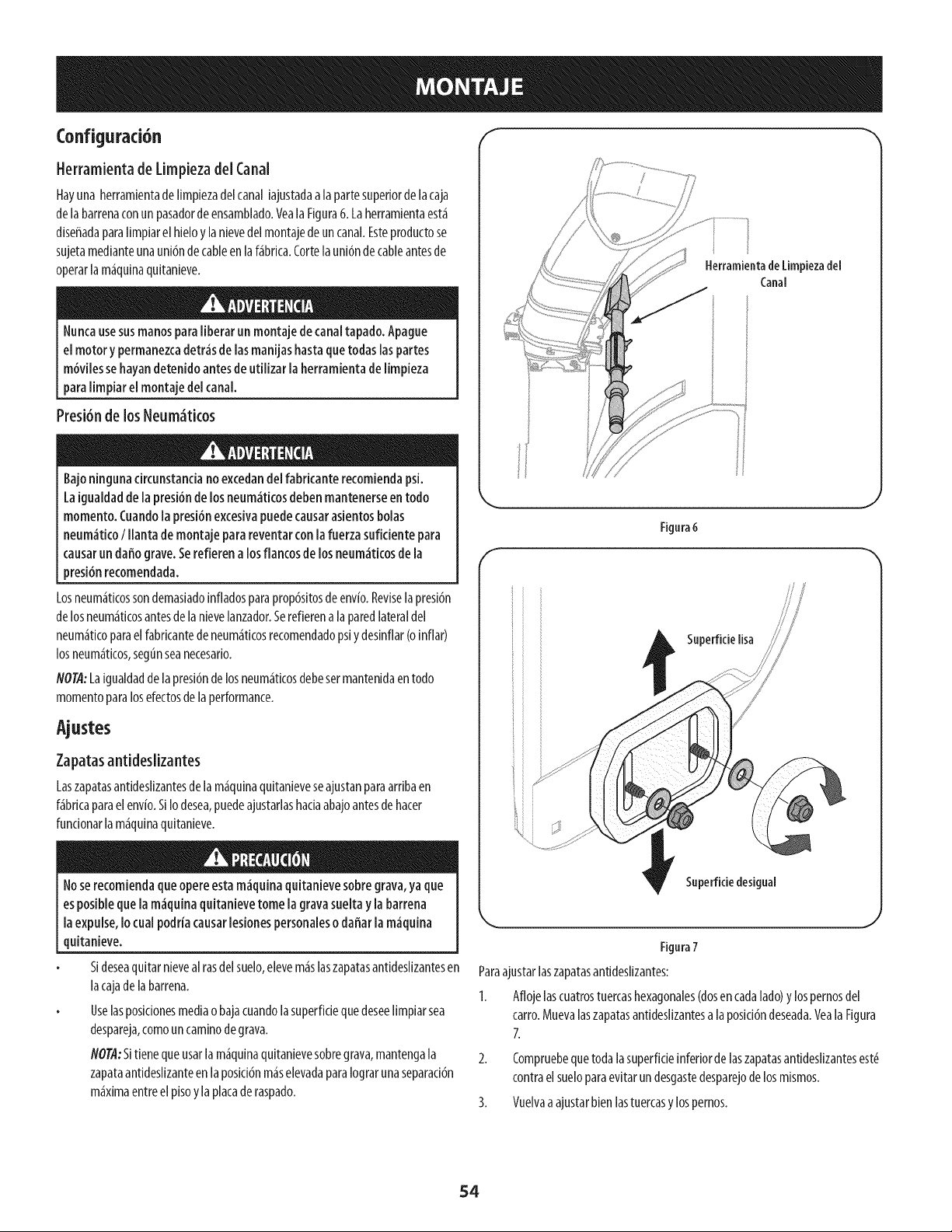
Configurad6n f -%
Herramienta de Limpieza del Canal
Hayuna herramientade Nmpiezadelcanaliajustadaala partesuperiorde lacaja
delabarrenaconun pasadorde ensamblado.Veala Figura6. Laherramientaest_
diseffadaparaNmpiarel hieloy lanievedelmontajede uncanal.Esteproductose
sujetamedianteunauni6ndecableen la f_bdca.Cortelauni6ndecableantesde
operarlam_quinaquitanieve.
Nuncausesusmanosparaliberarun montajede canaltapado. Apague
el motor y permanezcadetr_sde lasmanijashastacluetodas laspartes
m6vilessehayandetenido antesde utilizar laherramienta de limpieza
paralimpiar el montaje del canal.
Presi6nde los Neum_tkos
Bajoningunacircunstanciano excedandel fabdcanterecomiendapsi.
Laigualdadde la presi6nde losneum_tkos debenmantenerseen todo
momento.Cuandola presi6nexcesivapuedecausarasientosbolas
neum_ti(oI llanta de montaje papareventarcon lafuerza sufkiente para
causarun daffograve.Serefierena losflancosdelos neum_tkosde la
presi6nrecomendada.
Losneum<_tkossondemasiadoinfladosparaprop6sitosdeenvfo.Reviselapresi6n
delosneum_ticosantesdela nievelanzador.Serefierenalaparedlateraldel
neum<_ticoparaelfabdcantedeneum<_ticosrecomendadopsiydesinflar(oinflar)
losneum<_ticos,segtlnseanecesado.
NOTtl:Laigualdaddelapresi6nde losneum<_ticosdebesermantenidaentodo
momentoparalosefectosdela performance.
Ajustes
Zapatasantideslizantes
LaszapatasantidesNzantesde lam_quinaquitanieveseajustanparaardbaen
f_bdcaparael env[o.SIIodesea,puedeajustarlashadaabajoantesdehacer
fundonarlam_quinaquitanieve.
Noserecomiendaclueopereestam_guinaguitanievesobregrava,yaclue
esposiblecluela m_guinaguitanievetome lagravasueltay la barrena
laexpulse,Iocual podrfacausarlesionespersonaleso daffarla m_guina
quitanieve.
Sideseaquitar nieveal rasdelsuelo,elevem_slaszapatasantidesNzantesen
lacajadelabarrena.
Uselasposkionesmediao bajacuandola superfidequedeseeNmpiarsea
despareja,comouncaminodegrava.
NOT,4:Sitienequeusarlam<_quinaquitanievesobregrava,mantengala
zapataantidesNzanteenlaposici6nm<_selevadaparaIograrunaseparad6n
m<_ximaentreel pisoylaplacaderaspado.
Berramientade Limpiezadel
Canal
Fignra 6
f -%
Snperfide lisa
Superfide desigual
Fignra7
Paraajustarlaszapatasantideslizantes:
1. Aflojelascuatrostuercashexagonales(dosen cadalado)y lospernosdel
carro.Muevalaszapatasantideslizantesalaposici6ndeseada.Veala Figura
7.
2. Compruebequetodalasuperficieinferiordelaszapatasantideslizantesest6
contraelsuelopapaevitarundesgastedesparejode losmismos.
3. Vuelvaaajustarbienlastuercasy lospernos.
54
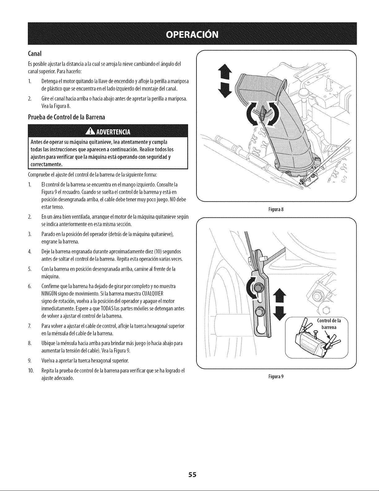
Canal F -'_
Esposibleajustarladistandaa lacualsearrojalanievecambiandoel_ngulodel
canalsuperior.Parahacerlo:
I. Detengael motorquitandolallavedeencendidoy aflojelaperillaa mariposa
depl_sticoqueseencuentraenel ladoizquierdodelmontajedelcanal.
2. Gireelcanalhadaarribaohaciaabajoantesdeapretarlaperillaamariposa.
VealaFigura8.
Pruebade Controlde la Barrena
Antesdeoperar sum_quina quitanieve,lea atentamenteycumpla
todas lasinstruccionesqueaparecena continuaci6n.Realicetodoslos
ajustesparaverificar quela m_quinaest_operandoconseguridady
correctamente.
Compruebeelajustedelcontroldelabarrenadelasiguienteforma:
1. Elcontroldelabarrenaseencuentraenelmangoizquierdo.Consultela
Figura9el recuadro.Cuandosesueltaelcontroldelabarrenayest_ien
posici6ndesengranadaarriba,elcabledebetenermuypocojuego.NOdebe
estartenso.
2.
Enun_ireabienventilada,arranqueelmotordelam_iquinaquitanievesegun
seindicaanteriormenteenestamismasecci6n.
3. Paradoen laposid6ndel operador(detkisdelam_iquinaquitanieve),
engranelabarrena.
4. Dejelabarrenaengranadaduranteaproximadamentediez(10)segundos
antesdesoltarelcontrolde labarrena.Repitaestaoperaci6nvariasveces.
5. Conlabarrenaenposici6ndesengranadaarriba,caminealfrentede la
m_iquina.
6. Confirmequela barrenahadejadodegirarporcompletoyno muestra
NINGONsignode movimiento.SilabarrenamuestraCUALQUIER
signode rotad6n,vuelvaa laposici6ndeloperadory apagueel motor
inmediatamente.EspereaqueTODASlaspartesm6vilessedetenganantes
devolvera ajustarelcontrolde la barrena.
Z Paravolvera ajustarelcabledecontrol,afloje latuercahexagonalsuperior
enlam_nsuladelcablede labarrena.
8. Ubiquelam_nsulahadaarribaparabrindarm_isjuego(ohadaabajopara
aumentarlatensi6ndelcable).Veala Figura9.
9. Vuelvaaapretarla tuercahexagonalsuperior.
10. RepitalapruebadecontroldelabarrenaparaverificarquesehaIogradoel
ajusteadecuado.
f
Figura 8
\\
J
'ii
1i
J
Figura 9
55
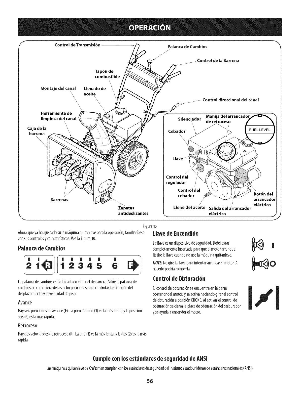
Control de Transmisi6n Palanca de Cambios
J
)J de la Barrena
Montaje del canal
Tapdn de
combustible
\
\
\
Llenado de
aceite
\\
\
Control direccional del canal
Herramienta de
limpieza del canal
Caja de la
barrena
\
\
\
Zapatas
antideslizantes
Silenci\ador deManijaretrocesodelarrancador
Cebador _._-_"
Llave
Control del
regulador /
Control del
cebador
Uene del
Salida del a! rancador
Botbn del
arrancador
el_ctrico
Figura10
Ahoraqueyahaajustadosulam_quinaquitanieveparalaoperacidn,familiarkese
consuscontrolesy caracteristicas.VealaFiguraI0.
Palancade Cambios
I' '
21 2345 6
Lapalancadecambiosest_ubicadaenel paneldecarrera.Situelapalancade
cambiosencualquierade lasochoposicionesparacontrolarladirecci6ndel
desplazamientoy lavelocidaddepiso.
Avarice
Hayseisposidonesdeavarice(F).Laposici6nuno(1)eslam_slenta,y laposici6n
seis(6)eslam_sr_pida.
[lave de Encendido
LaIlaveesundispositivodeseguridad.Debeestar
completamenteinsertadaparaqueelmotorarranque.
RetirelaIlavecuandonouselam_quinaquitanieve.
NOTE:NogirelaIlaveparaintentararrancarelmotor.AI
hacerlopodriaromperla.
Control deObturaci6n
Elcontroldeobturaci6nseencuentraen laparte
posteriordelmotor,yseactivahadendogirar elcontrol
de obturad6naposid6nCHOKE.AIactivarelcontrolde
obturaci6nsederralaplacadeobturaci6ndelcarburador
y seayudaaencenderel motor.
Retroceso
Haydosvelocidadesderetroceso(R).Launo(I) eslam_slenta,yla dos(2)eslam_s
r_pida.
Cumpleconlos est_ndaresdeseguridaddeANSI
Lasm_quinasquitanievedeCraftsmancumplenconlosest_ndaresdeseguridaddelinstitutoestadounidensedeest_ndaresnacionales(ANSI).
56
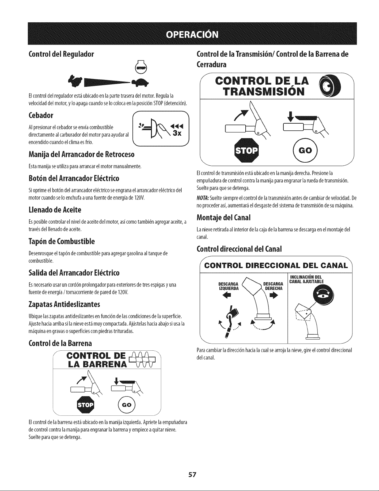
Control del Regulador
Elcontroldel reguladorest_ubicadoenla partetraseradelmotor.Regula[a
velocidaddelmotor,yIoapagacuandoseIocolocaenla posid6nSTOP(detend6n).
Cebador
AIpresionarelcebadorseenviacombustible
directamentealcarburadordelmotorparaayudaral
encendidocuandoelclimaesffio.
Manijadei Arrancadorde Retroceso
Estamanijaseutilizaparaarrancarelmotormanualmente.
Bot6n delArrancadorEi_ctri¢o
Sioprimeelbot6ndelarrancadorel_ctricoseengranaelarrancadorel_ctricodel
motorcuandoseIoenchufaaunafuentedeenergiade120V.
Uenado de Aceite
Esposiblecontrolarel niveldeaceitedel motor,as[comotambi_nagregaraceite,a
trav_sdel Ilenadodeaceite.
Tap6ndeCombustible
Desenrosqueeltap6nde combustibleparaagregargasolinaaltanquede
combustible.
Salida deiArrancadorEi_ctri¢o
Esnecesafiousaruncord6nprolongadorparaextefioresde tresespigasy una
fuentedeenergia/ tomacorfientede paredde120V.
ZapatasAntideslizantes
Ubiquelaszapatasantideslizantesenfunci6ndelascondicionesdelasuperficie.
Ajustehaciaarribasilanieveest_muycompactada.Ajtistelashaciaabajosiusala
m_quinaengravasosuperficiesconpiedrastrituradas.
Control dela Barrena
J CONTROL DE __
LA BARRENA
Elcontrolde la barrenaest_ubkadoenlamanijaizquierda.Apfietelaempuffadura
decontrolcontralamanijaparaengranarlabarrenay empiecea quitarnieve.
Suelteparaquesedetenga.
Control de ia Transmisi6n/Controlde ia Barrena de
Cerradura
f
CONTROL DE LA
TRANSMISION
Elcontroldetransmisi6nest_ubicadoenlamanijaderecha.Presionela
empuffaduradecontrolcontralamanijaparaengranarla ruedadetransmisi6n.
Suelteparaquesedetenga.
NOTA:Sueltesiempreelcontrolde la transmisi6nantesdecambiardevelocidad.De
noprocederas[,aumentar_eldesgastedel sistemadetransmisi6nde sum_quina.
Montajedei Canal
Lanieveretiradaal interiordelacajadelabarrenasedescargaenelmontajedel
canal.
Control directionaldei Canal
f
CONTROL DIRECCIONAL DEL CANAL
INCLINACI6N DEL
CAHALAJUSTABLE
DESCARGADESCARGA
IZQUIEBDA
Paracambiar ladirecddn hada la cualse arroja la nieve,gire el controldirecdonal
delcanal.
57
Herramientade Limpieza
Nuncausesusmanosparaliberarun montajede canaltapado.Antesde
destaparlo,apagueel motor y permanezcadetr_sdelasmanijashastaque
todaslaspartesm6vilessehayandetenido.
Laherramientadelimpiezadelcanalest_iajustadaconvenientementea la parte
posteriorde [acajade[abarrenaconun pasadordeensamb[ado.Siseacumu[an
nievey hie[oenelcanalde descargadurante[aoperad6n,procedacomoseindica
acontinuaci6npara[impiardemaneraseguraelmontajede[ canaly [aaberturade[
canal
1. Suelteelcontrolde labarrenayel controlde latransmisi6n.
2. ParadetenerelmotorsaquelaIlavede encendido.
3. Saquelaherramientadelimpiezadelpasadorquela ajustaa la parte
posteriorde lacajadelabarrena.
4. Useelextremoconformade palade laherramientadelimpiezapara
desplazary recogerlanievey el hieloqueseformaroncercadelconjuntodel
canal.
5. Vuelvaaajustarla herramientadelimpiezaalpasadorde ensamblado
ubicadoenla parteposteriordelacajadelabarrena,insertede nuevola
Ilavedeencendidoyenciendael motordelam_iquinaquitanieve.
6. Paradoenla posici6ndeloperador(detr_isdelam_iquinaquitanieve),
engraneelcontroldelabarrenaduranteunossegundosparaeliminarla
nieveoel hieloquehayanquedadoenelconjuntodelcanal.
Antesde Encenderel Motor
Aceite
Gasoiina
Utilicegasolinaparaautom6viles(sinplomooconbajocontenidode plomopara
minimizarlosdep6sitosenlac_maradecombusti6n)conunoctanajem[nimode 87.
Sepuedeusargasolinaconhastaun 10%deetanoloun 15%deMTBE(#termet[lico
terciario-but[lico).Nuncauseunamezcladeaceitey gasolinanigasolinasuda.Evite
queselntroduzcasuciedad,polvooaguaeneltanquedecombustible.NOutllice
gasolinaE85.
Carguecombustibleen un_reabienventiladay conel motorapagado.No
fume ni permitallamasochispasenel lugardondesecargacombustibleose
encuentraeldep6sitodecombustibledelmotor.
NoIleneenexcesoel tanquedecombustible.Despu#sde cargarcombustible,
aseguresedequeel tap6ndeltanqueest#biencerradoy asegurado.
Tengacuidadode noderramarcombustibleal realizarla recarga.El
combustiblederramadoosusvaporessepuedenincendlar.Sisederrama
combustible,aseguresedequeel_reaest#secaantesdearrancarelmotor.
Eviteel contactorepetidoo prolongadoconlapielo inhalarlosvapores.
Tengaextremo cuidadocuandomanipuiegasolina.Lagasolinaes
aitamenteinflamabley susvaporespuedencausarexplosiones.Nunca
agreguecombustiblea [am_quina eninterioreso mientras elmotor est_
calienteo en funcionamiento.Apagueloscigarrillos,cigarros,pipasy otras
fuentesdecombusti6n.
1.
2.
Antesde sacarlatapaparacargarcombustible,limpiealrededor.
Enel tanquedecombustiblehayunindicadorde nivel.Lleneeltanquehasta
Ilegaral niveldecombustibledel indicador.Veala Figura10.Tengacuidado
paranoIlenarel dep6sitoenexceso.
Encendidodei Motor
Lea,cornprenday sigatodas lasinstruccionesy advertenciasqueaparecen
en la m_quinayen estemanualantesde operarla.
Elmotorseenvi6conaceiteen elmotor.Controleelnivelde acelteantesdecada
operaci6nparaasegurarsedequehayaaceitesuficienteenelmotor.
NOTA:Aseguresede comprobarel motorsobreunasuperficieniveladayconel
motorapagado.
1. Retireeltap6ndeIlenado/la varillademedid6nde niveldeaceitey limpie
lavarilla.
Inserteeltap6n/lavarillademedici6nenelcuellodeIlenadodeaceite,pero
nolaatornille.
3. Extraigaeltap6nde Ilenado/la varilladeniveldeaceite.Sielnivelesbajo,
agregueaceite(5W-30,conunadasificaci6nminimadeSF/%)lentamente
hastaqueelregistromarqueentrenivelalto (H)y bajo(L).
NO@:NoIo Ileneenexceso.ElIlenadoexcesivode aceitepuedehacerqueel motor
generehumo,quecuestearrancarloofallasenlabuj[a.
4. Vuelvaacolocareltap6n/la varilladeaceitey ajusteconfirmezaantesde
arrancarel motor.
Siempremantengalasmanosy lospiesalejadosde laspartesm6viles.No
utilice fluidos comprimidosparaarrancar.Losvaporesson inflamables.
NOI'A:Dejequeelmotorsecalienteduranteunosminutostraselarranque.Elmotor
nodesarrollar_itodasupotendahastaquealcancetemperaturasoperativas.
1. Aseguresedequeelcontroldelabarrenayelcontroldelatransmisi6nest_n
enposici6ndesengranada(sinpresionar).
2. InsertelaIlaveenlaranura.Aseguresedequeentreapresi6nensulugar.No
intentegirarlaIlave.
NOTA:ElmotornopuedearrancarsilaIlavenoest_icompletamenteinsertadaenel
interruptordeencendido.
58
ArrancadorEl ctrko
Elarrancadorei_ctricoest_equipadoconun enchufedetres terminaies
conectadosatierra y est_diseffadoparaoperarconcorrientedom_stica
de 120voltios. Debeserutilizado conun recept_culode tresterminales
correctamenteconectadoa tierra en todo momentopara evitar
la posibilidad dedescargasel_ctricas.Sigatodas lasinstrucciones
cuidadosamenteparaoperarelarrancadorel_ctrico.NOutilice el
arrancadorel_ctrico bajola Iluvia.
Determinesiel caNeadodesuhogaresunsistemadetrescanesconectadoatJerra.
Consulteconunelectricistamatrkuladosinoest_iseguro.
Sicuentaconunrecept_icuiodetresterminaies,sigalossiguientespasos.Sie[
cableadodesuhogarnoeseladecuado,NOuseelarrancadorel6ctricoenninguna
drcunstanda.
Conecteel prolongadora lasalidasituadaenlasuperfidedelmotor.Conecte
elotroextremodel prolongadoren unrecept_iculodeCAconconexi6na
tierradetresterminalesde120voltios,en un_ireabien ventilada.
1. Muevala palancade controldel reguladorala posid6nFAST(r_ipido,
representadaporunaliebre_ ).
2. Muevalapalancadelcebadorhastalaposid6nCHOKE1,'_1 (encendidocon
el motorenif[o). Siel motoryaest_icaliente,ubiqueel cebadorenlaposid6n
OFF.
3. Presioneel cebadortres(3)veces,asegur_ndosede cubrirelorifido de
ventilad6ncuandoIo haga.Siel motorest_caliente,presioneelcebadoruna
solavez.Cubrasiempreelorifido deventilad6ncuandooprimaelbot6ndel
cebador.Sihacefrio puederesultarnecesariorepetirel cebado.
4. Jalesuavementelamanijadelarrancadorhastaquecomienceaofrecer
resistenda,luegoj_lelar_pidamentey confuerzaparasuperarla
compresi6n.Nosueltelamanijani permitaquesedesenganche.Vuelvala
cuerdaLENTAMENTEasuposici6noriginal.Desetnecesario,repitaestepaso.
5. Mientrassecalientaelmotor,girelentamenteelcontroldelobturadorala
posid6nOFF(apagado).Sielmotorsedetiene,vuelvaaencenderlo,h_galo
fundonarconelcebadoren suposici6nmediaduranteunlapsobrevey
luegogirelentamenteel cebadorhastalaposid6nOFF(apagado).
Elcabledeextensi6npuedeserdecualquier[ongitud, perodebe ser
dasificadopara15amperiosa 125voitios, tierra y ciasificadoparasuuso
en exteriores.
2. Muevalapalancadecontroldelreguladoralaposid6nFAST(kipido,
representadaporunaliebre).4_J_II
3. Muevalapalancadelcebadorhastalaposki6nCHOKEI,"l (encend docon
elmotorenfrio).Siel motoryaest_caliente,ubiqueelcebadoren laposid6n
OFF.
4. Presioneel cebadortres(3)veces,asegur_ndosedecubrirelorifido de
ventilad6ncuandoIohaga.Sielmotorest_caliente,presioneelcebadoruna
solavez.Cubrasiempreel orifido deventilaci6ncuandooprimaelbot6ndel
cebador.Sihacefriopuederesultarnecesariorepetirelcebado.
5. Presioneel bot6ndelarrancadorparaarrancarel motor.Unavezencendido
elmotor,suelteinmediatamenteelbot6ndelarrancador.Elarrancador
el#ctricotieneunaprotecd6ncontrasobrecargat#rmica;elsistemase
apagar_transitoriamenteparapermitirqueseenfrieelarrancadoren caso
quesesobrecargueelarrancadorel#ctrko.
6. Mientrassecalientaelmotor,girelentamenteel controldelobturadorala
posid6nOFF(apagado).Sielmotorsedetiene,vuelvaaencender[o,h_galo
fundonarconel cebadorensuposici6nmediaduranteun lapsobrevey
luegogirelentamenteelcebadorhastala posid6nOFF(apagado).
7. Unavezqueel motorest#enfundonamiento,desconectedelarrancador
el#ctricoel cabledealimentad6n.Paradesconectarlo,desenchufe
siempreel extremoqueest_enchufadoaltomacorrientede paredantesde
desenchufarelextremoopuestoqueest_conectadoalmotor.
Arrancadorde Retroceso
Notire de [a manijade[arrancadormientrasel motor est_ en marcba.
Paraevitar queel motorfuncionesin control,nuncaIo deje sinvigilancia
mientrasest_en marcba.Apagueel motor luegodeusarloy saquela flare.
Detenci6ndel Motor
Dejeencendidoel motordurantealgunosminutosantesdedetenerloparapermitir
quesesequelahumedadenel mismo.
1. Muevael controldel reguladora laposici6nOFE
2. RetirelaIlave.AIretirarlaIlavesereducelaposibilidadde queelmotorsea
puestoen marchasinautorizad6nmientrasel equiponoest_enuso.Guarde
la Ilaveen unlugarseguro.Elmotorno puedearrancarsinla Ilave.
3. Eliminelahumedadde loscontrolesdelmotor.
Procedimientopara Engranaria Transmisi6n
1. Conel controldelestranguladoren posid6nr_pida_ (dibujode un
conejo),muevala palancadecambiosa unade lasseisposicionesde avance
(F)o delasdosposidonesde reversa(R).Selecdonelaveloddadadecuada
paraelestadode lanieveexistentey unaveloddadconlaquesesienta
c6modo.
Aprieteelcontrolde latransmisi6ncontrala manijaderecha,y la m_quina
quitanlevesemover&Su6lteloy sedetendr_el movimientodela
transmisi6n.
flOT/l:NUNCAcambiela poslci6ndelapalancadecambios(cambiodevelocidades
o dedirecd6nde desplazamiento)sinsoltarprimeroelcontrolde transmisi6ny
detenerporcompletolam_quinaquitanieve.Estoproducir_un desgasteprematuro
delsistemadetransmisi6nde lam_quinaquitanieve.
Procedimiento para Engranar ias Barrenas
1. Aprieteelcontrolde labarrenacontralamanijay lasbarrenasrotar_n.
Su_ltelay lasbarrenassedetendr_n.
59

PROGRAMADEMANTENIMIENTO
Antesde realizarcualquiertipo del mantenimiento/servicio,suelte
todos losmandosy pareel motor. Esperehastaquetodaslaspartesde
movimiento hayanvenido auna paradacompleta.Desconecteel alambre
de bujia y b_selocontrael motor paraprevenirel comienzoinvoluntario.
Siemprellevepuestoscristalesinastillablesdurante la operaci6no
realizandocualquierajusteo reparadones.
Sigael cronogramade mantenimientoquesepresentaacontinuaci6n.Estatabla
s61odescribepautasdeservicio.UtilicelacolumnaRegistrodeServicioparahacerel
seguimientodelastareasde mantenimientocompletadas.PanubicarelCentrode
ServicioSearsm_scercanoo paraprogramarunservicio,simplementecomuniquese
conSearsal tel6fono1-800-4-MY-HOME®.
CadaUsoy 5horas
los5
Anualmenteo25horas
Anualmenteo50 horas
Anualmenteo100horas
AntesdeAlmacenaje
1. Niveldelaceitedemotor
2. Hardwaresueltoo ausente
3. Unidady motor
1. Elaceitedemotor
1. Bujia
2. Encadenamientosdecontroly pivotes
3. Ruedas
4. Ejede engranajeyejedela barrena
1. Elaceitedemotor
1. Bujia
1. Sistemadecombustible
1. Comprobar
2. Aprieteosustltuir
3. Limpio
1. Cambio
1. Comprobar
2. Lubricaci6nconpetr61eoligero
3. Lubricaci6nconautomotoresmultiusos
4. Lubricaci6nconpetr61eoligero
I. Cambio
1. Cambio
1. Elmotordirigidohastaqueestosepareafalta
delcombustible
Mantenimiento de Motor
f
Antesde realizartareasde lubricaci6n,reparaci6no inspecci6n,
desengranetodos loscontrolesy detenga elmotor. Esperea quese
detengantodaslaspiezasm6viles.
Control del Aceite del Motor
flOTA:Verifiqueel niveldeaceiteantesde cadausoparacerciorarsequese
mantieneelniveldeaceiteindicado.
Cuandoleagregueaceitealmotor,consultelasiguientetabladeviscosidad.La
capaddadde aceitedelmotores600ml (aprox.20onzas).NoIleneexcesivamente.
Useunaceiteparamotordecuatrotiempos,o unaceitedetergentedecalidad
Premiumconcertificadoquecubraoexcedalasexigendasde losfabricantesde
autom6vilesamerkanosrespectodelaclasificaci6ndeservkioSGy SELosaceites
paramotorconlaclasificad6nSG,SFtienenest_designaci6nen elenvase.
1. Retireeltap6ndeIlenadode aceitey limpielavarillademedid6ndeaceite.
2. Insertelavarillademedici6nenel cuellodeIlenadode aceite,perono Io
atornille.
3. Retireeltap6ndeIlenadode aceite.Sielnivelest_bajo,agregueaceite
lentamentehastaregistrosdeniveldel aceiteentrealto(H)y bajo (L).Veala
Figura11.
4. Ajustefirmementelavarillademedici6nantesdearrancarelmotor.
Figura 11
J
60
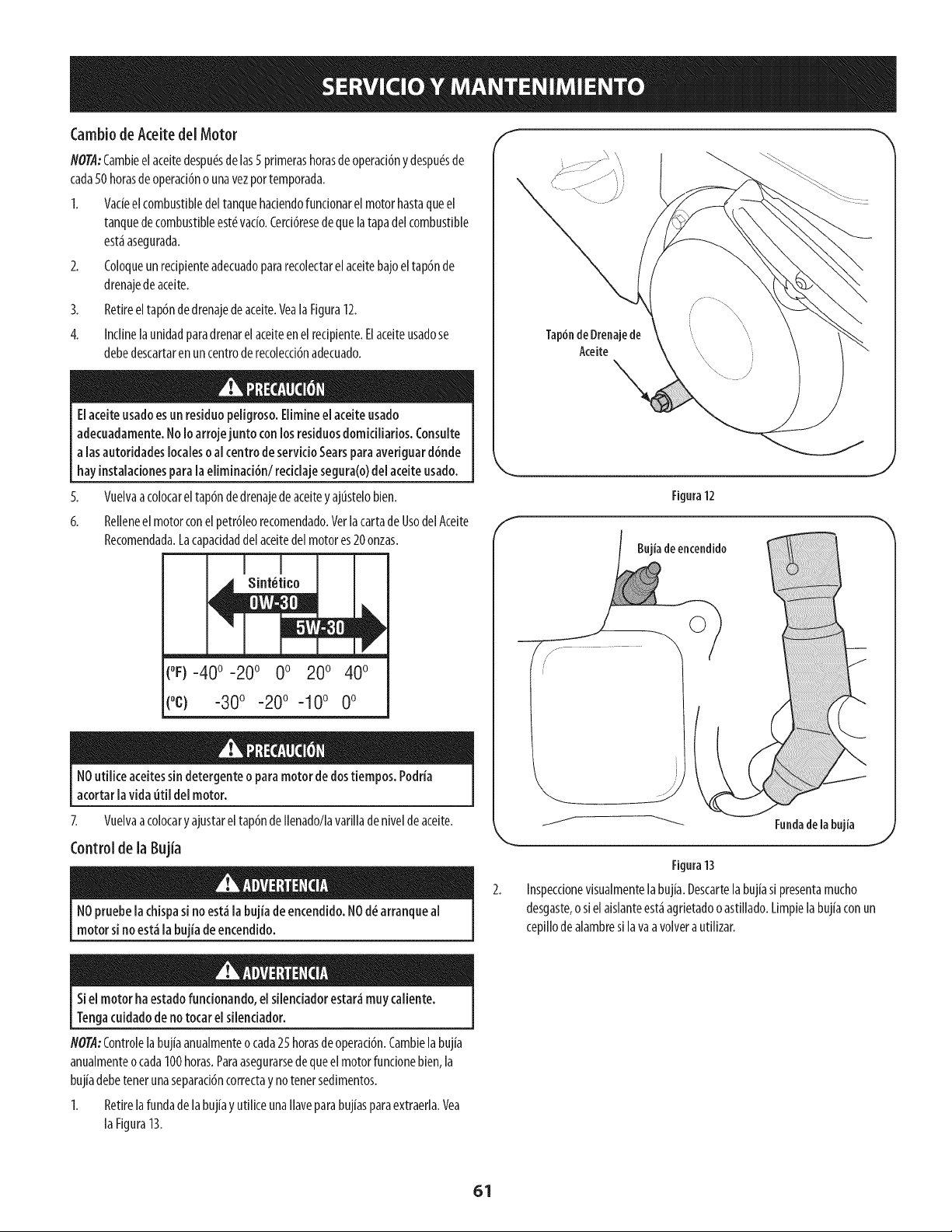
CambiodeAceitedel Motor
NOTA:Cambieelaceitedespu_sdelas5 primerashorasdeoperaci6ny despu_sde
cada50horasdeoperaci6no unavezportemporada.
1. Vacieel combustibledeltanquehaciendofuncionarel motorhastaqueel
tanquede combustibleest_ratio. Cerci6resede quelatapadelcombustible
est_asegurada.
2. Coloqueunrecipienteadecuadopararecolectarelaceitebajoeltap6nde
drenajedeaceite.
3. Retireeltap6ndedrenajedeaceite.VealaFigura12.
4. Inclinelaunidadparadrenarelaceiteenel redpiente.Elaceiteusadose
debedescartaren uncentroderecolecci6nadecuado.
EIaceiteusadoesun residuopeiigroso.Eiimineel aceiteusado
adecuadamente.No1oarrojejunto con losresiduosdomiciiiarios.Consuite
alas autoridadeslocalesoal centrode servicioSearsparaaveriguard6nde
hayinstalacionespara[aeliminaci6n/recidaje segura(o)del aceiteusado.
5.
6.
Vuelvaacolocareltap6ndedrenajedeaceitey ajtistelobien.
Relienee[ motorcone[petr61eorecomendado.VerlacartadeUsodelAceite
Recomendada.Lacapacidaddelaceitedelmotores20onzas.
(°F)-40 °-20 ° 0 o 200 400
(oc) -300 -200 -10° 0°
NOutiiice aceitessin detergenteo paramotor dedostiempos.Podria
acortar [avida uti[ de[ motor.
Z Vuelvaacolocaryajustareltap6ndeIlenado/lavarilladeniveldeaceite.
Control de la Bujia
NOpruebela chispasi noest_ la bujia de encendido.NOd_ arranqueal
motor si noest_ la bujia de encendido.
Tap6ndeDrenajede
Aceite
Figura12
Bujiade encendido
J
Fundadelabujia
J
Figura13
Inspeccionevisualmentelabujia.Descartela bujiasi presentamucho
desgaste,o sielaislanteest_agrietadooastillado.Limpielabuj[aconun
cepillodealambresi lava avolvera utllizar.
Siel motor haestado funcionando,elsilendador estar_muy caliente.
Tengacuidadodeno tocar elsilendador.
NOTA:Controlelabuj{aanualmenteocada25 horasdeoperad6n.Cambielabujia
anualmenteocada100horas.Paraasegurarsedequeelmotorfundonebien,la
buj[adebetenetunaseparad6ncorrectay notenetsedimentos.
1. Retirelafundadelabuj[ayutiliceunaIlaveparabuj[asparaextraerla.Vea
laFigura13.
61
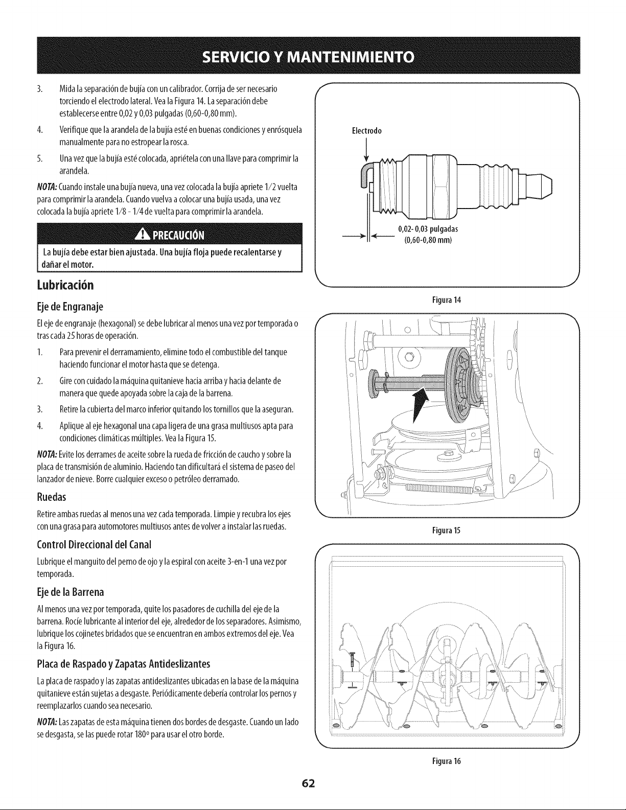
4,
5,
Midalaseparad6ndebujiaconuncalibrador.Cordjadesernecesado
tordendoelelectrodolateral.Veala Figura14.Laseparaci6ndebe
establecerseentre0,02y 0,03pulgadas(0,60-0,80mm).
VerMquequelaarandeladelabujiaest_enbuenascondlclonesy enr6squela
manualmenteparanoestropearlarosca.
Unavezquelabujiaest_colocada,aprl_telaconunallaveparacompdmlrla
arandela.
NOTA:Cuandoinstaleunabujianueva,unavezcoIocadalabujiaaprieteI/2 vuelta
paracomprimirlaarandela.Cuandovuelvaa colocarunabujiausada,unavez
colocadalabujiaaprieteI/8 - I/4 devueltaparacomprimirlaarandela.
Labujia debeestar bienajustada.Unabujia floja puederecalentarsey
dafiar el motor.
f
Electrodo
0,02-0,03pulgadas
(0,60-0,80ram)
Lubricad6n
Ejede Engranaje
Elejedeengranaje(hexagonal)sedebelubdcaralmenosunavezportemporadao
trascada25 horasdeoperaci6n.
I. Paraprevenlrel derramamlento,ellmlnetodoelcombustibledeltanque
hadendofuncionarelmotorhastaquesedetenga.
2. Glreconcuidadolam_quinaqultanlevehadaardbay hacladelantede
maneraquequedeapoyadasobrelacajadelabarrena.
3. Retirelacubiertadel marcoinferiorquitandolostornlllosquelaaseguran.
4. Apllquealejehexagonalunacapaligeradeunagrasamultiusosaptapara
condlclonescllm_ticasmultiples.Veala Flgura15.
NOTA:Evltelosderramesdeaceitesobrelaruedadefrlccl6ndecauchoy sobrela
placadetransmisi6ndealumlnio.HadendotandMcultar_elsistemade paseodel
lanzadorde nleve.Borrecualqulerexcesoo petr61eoderramado.
Ruedas
Retireambasruedasal menosunavezcadatemporada.Limpiey recubralosejes
conunagrasaparaautomotoresmultiusosantesdevolveralnstalarlasruedas.
Control Direccionaldel Canal
Lubdqueelmanguitodelpernodeojoy laespiralconaceite3-en-1unavezpor
temporada.
Ejede la Barrena
AImenosunavezportemporada,quitelospasadoresdecuchllladelejedela
barrena.Rocielubdcanteal interiordeleje,alrededorde losseparadores.Aslmismo,
lubdqueloscojinetesbddadosqueseencuentranenambosextremosdeleje.Vea
laFigura16.
Plata de Raspadoy ZapatasAntideslizantes
Laplacade raspadoy laszapatasantideslizantesubicadasenlabasedelam_quina
quitanleveest_nsujetasadesgaste.Ped6dlcamentedeberiacontrolarlospernosy
reemplazarloscuandoseanecesado.
NOT.4:Laszapatasdeestam_qulnatienendosbordesdedesgaste.Cuandounlado
sedesgasta,selaspuederotar 1800parausarel ottoborde.
Figura14
J
Figura15
!
Figura16
62
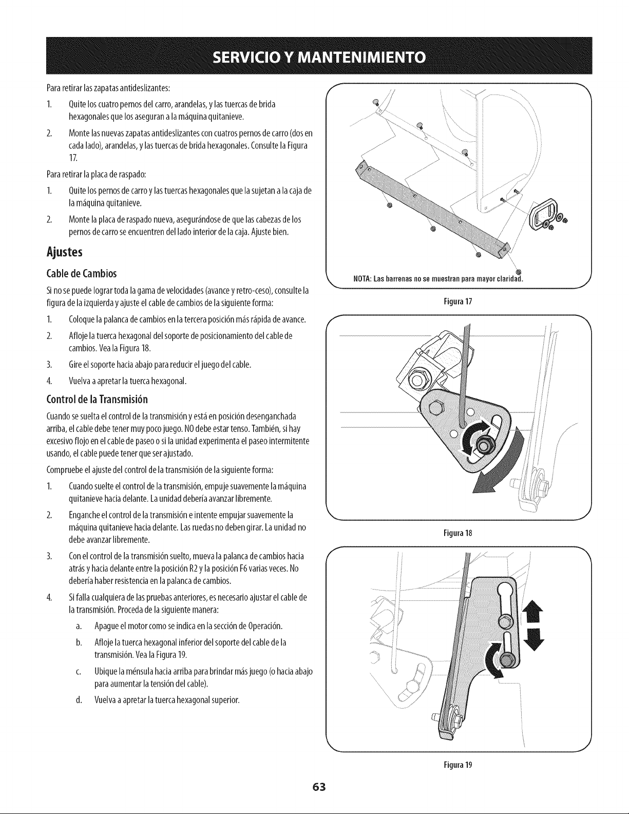
Pararetirar[aszapatasantidesNzantes:
1. Quiteloscuatropernosdelcarro,arandelas,y [astuercasde brida
hexagonalesquelosasegurana lam£quinaquitanieve.
2. MontelasnuevaszapatasantidesNzantesconcuatrospernosdecarro(dosen
cadalado),arandelas,y lastuercasde bridahexagonales.Consultela Figura
17.
Pararetirarla placade raspado:
I. Quitelospernosdecarroy lastuercashexagonalesquelasujetanalacajade
lam£quinaquitanieve.
2. Montelaplacaderaspadonueva,asegur£ndosedequelascabezasdelos
pernosdecarroseencuentrendel ladointeriordelacaja.Ajustebien.
Ajustes
CabledeCambios
SinosepuedeIogrartodalagamade veloddades(avancey retro-ceso),consultela
figuradela izquierday ajusteelcabledecambiosdelasiguienteforma:
1. Coloquelapalancadecambiosenlaterceraposici6nm£sr£pidadeavance.
2. Aflojelatuercahexagonaldelsoportede posidonamientodelcablede
cambios.YealaFigura18.
3. Gireelsoportehadaabajopararedudreljuegodelcable.
4. Vuelvaaapretarla tuercahexagonal.
Controlde laTransmisi6n
Cuandosesueltael controldelatransmisi6nyest_enposid6ndesenganchada
arriba,elcabledebetenetmuypocojuego.NOdebeestartenso.Tambi_n,sihay
excesivoflojo enelcablede paseoo silaunidadexperimentael paseointermitente
usando,el cablepuedetenetquesetajustado.
Compruebeel ajustedel controlde latransmisi6ndelasiguienteforma:
1. Cuandosuelteelcontroldelatransmisi6n,empujesuavementelam£quina
quitanievehadadelante.LaunidaddeberfaavanzarNbremente.
2. Engancheel controldelatransmisi6neintenteempujarsuavementela
m£quinaquitanievehadadelante.Lasruedasno debengirar.Launidadno
debeavanzarNbremente.
3.
4.
Conelcontroldelatransmisi6nsuelto,muevalapalancadecambioshacia
atr£sy hadadelanteentrelaposid6nR2y laposid6nF6variasveces.No
deberfahaberresistenciaenlapalancadecambios.
Sifallacualquieradelaspruebasanteriores,esnecesarioajustarel cablede
latransmisi6n.Procedade lasiguientemanera:
a. Apagueelmotorcomoseindicaenlasecci6ndeOperaci6n.
b. Aflojelatuercahexagonalinferiordelsoportedel cabledela
transmisi6n.Yeala Figura19.
c. Ubiquela mdnsulahaciaarribaparabrindarm£sjuego(ohaciaabajo
paraaumentarlatensi6ndelcable).
d. Vuelvaaapretarlatuercahexagonalsuperior.
f
NOTA:Las barreoas no se muoslraa para mayor claridad.
J
Fitura 17
\
Filura18
J
Figura19
63
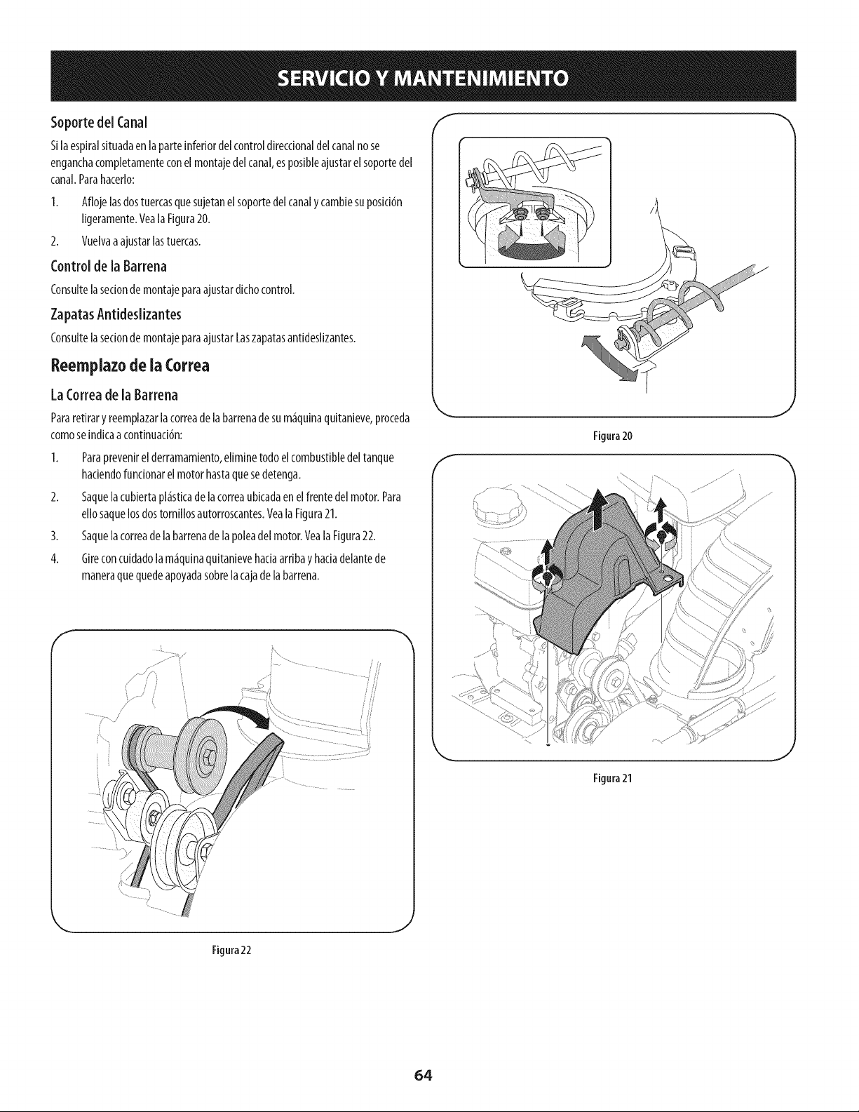
SoportedelCanal
Silaespiralsituadaen laparteinferiordelcontroldireccionaldelcanalno se
enganchacompletamenteconelmontajedelcanal,esposibleajustarelsoportedel
canal.Parahacerlo:
1. Aflojelasdostuercasquesujetanelsoportedelcanaly cambiesuposici6n
ligeramente.VealaFigura20.
2. Vuelvaaajustarlastuercas.
Controlde la Barrena
Consultelasecionde montajeparaajustardichocontrol.
ZapatasAntideslizantes
Consultelasecionde montajeparaajustarLaszapatasantideslizantes.
Reemplazode ia Correa
LaCorreadela Barrena
Pararetirary reempiazarla correadelabarrenadesum_quinaquitanieve,proceda
comose[ndicaacontinuad6n:
1. Paraprevenirel derramamiento,eliminetodoel combustibledeltanque
hadendofuncionarelmotorhastaquesedetenga.
2. Saquelacubiertapl_sticade lacorreaubicadaen elfrentedel motor.Para
ellosaquelosdostornillosautorroscantes.VealaFigura21.
3. Saquelacorreade labarrenade lapoleadel motor.Veala Figura22.
4. Glreconcuidadolam_quinaqultanlevehadaarrlbay hadadelantede
maneraquequedeapoyadasobrelacajadelabarrena.
/
f
Figura21
_J
Figura22
64
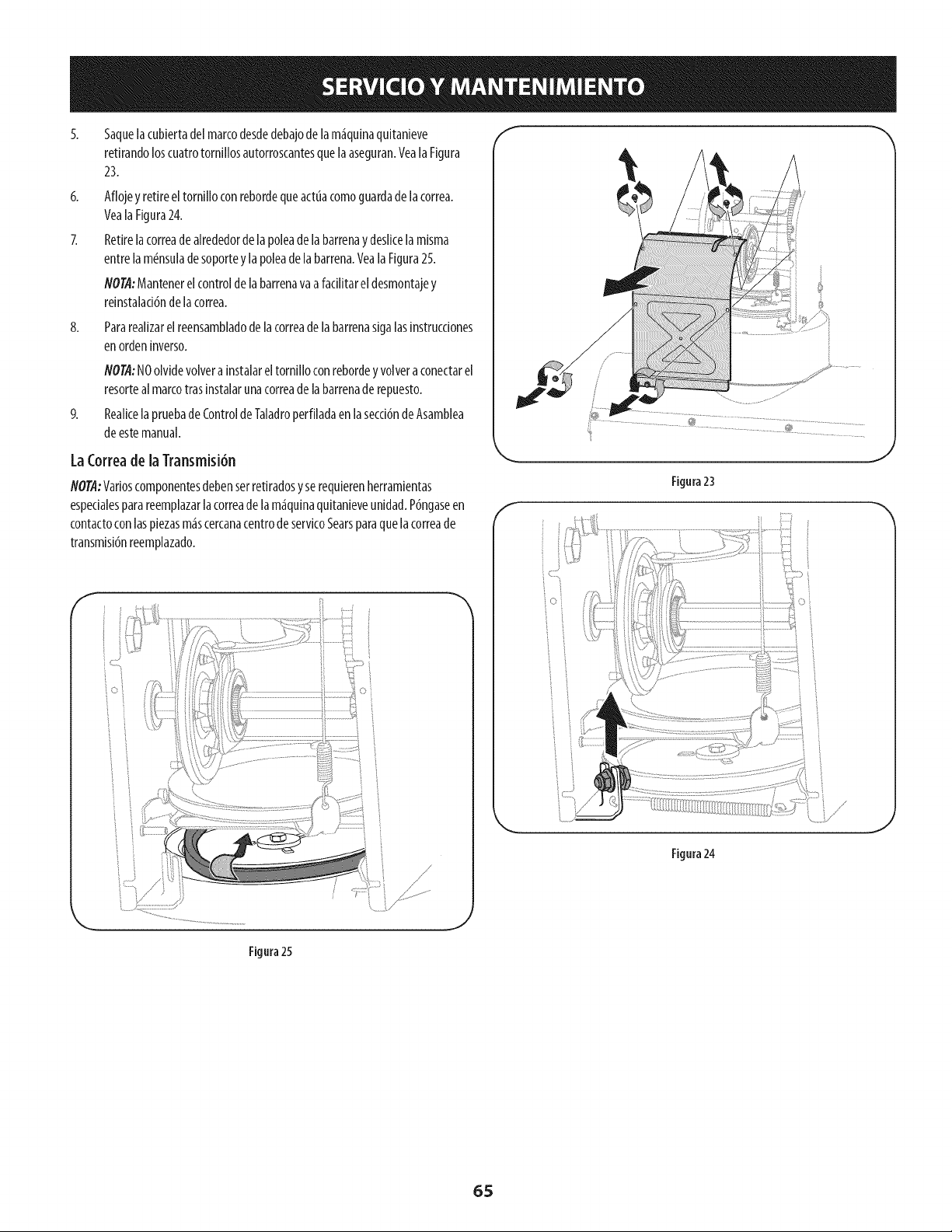
6,
8,
5aquelacubiertadelmarcodesdedebajode lam_quinaquitanieve
retirandoloscuatrotornillosautorroscantesquelaaseguran.VealaFigura
23.
Aflojey retireeltornilloconrebordequeactuacomoguardadelacorrea.
YealaFigura24.
Retirelacorreadealrededordelapoleadelabarrenaydeslicela misma
entrelam6nsuladesoportey lapoleadelabarrena.YealaFigura25.
NOTA:Mantenerelcontroldelabarrenavaafacilitareldesmontajey
reinstalad6ndelacorrea.
Pararealizarelreensambladodelacorreadelabarrenasigalasinstrucciones
enordeninverso.
NOTA:NOolvidevolvera instalareltornilloconrebordeyvolveraconectarel
resorteal marcotrasinstalarunacorreadelabarrenaderepuesto.
RealicelapruebadeControldeTaladroperfiladaenla secci6ndeAsamblea
deestemanual.
LaCorreade laTransmisi6n
NOTA:Varioscomponentesdebenserretiradosyserequierenherramientas
espedalesparareemplazarlacorreadelam_quinaqultanieveunidad.P6ngaseen
contactoconlaspiezasm_scercanacentrodeservicoSearsparaquelacorreade
transmisi6nreemplazado.
//
Figura23
Figura24
Figura25
65
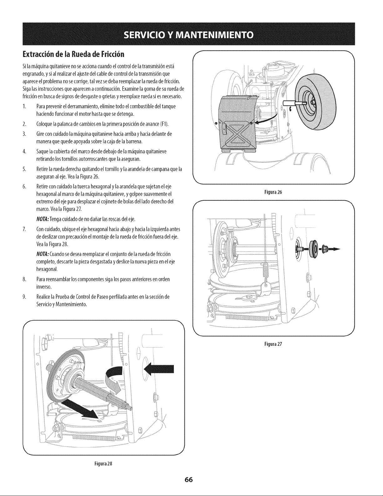
Extracci6n de ia Eueda de Fricci6n _
Silam_quinaquitanievenoseacdonacuandoelcontrolde la transmisi6nest_
engranado,y sialrealizarelajustedelcabledecontroldelatransmisi6nque
apareceelproblemanosecorrige,tal vezsedebareemplazarlaruedadefrkd6n.
Sigalasinstruccionesqueaparecenacontinuad6n.Examinelagomadesuruedade
fricci6nen buscadesignosdedesgasteo grietasy reemplaceruedasi esnecesario.
I. Paraprevenirel derramamiento,eliminetodoelcombustibledeltanque
hadendofundonarelmotorhastaquesedetenga.
2. Coloquelapalancadecambiosenlaprimeraposid6nde avance(FI).
3. Gireconcuidadolam_quinaquitanievehaciaarribay hadadelantede
maneraquequedeapoyadasobrelacajadelabarrena.
4. Saquelacubiertadelmarcodesdedebajode lam_quinaquitanieve
retirandolostornillosautorroscantesquelaaseguran.
5. Retirelaruedaderechaquitandoel tornilloylaarandeladecampanaquela
aseguranaleje.VealaFigura26.
6. Retireconcuidadolatuercahexagonalyla arandelaquesujetaneleje
hexagonalalmarcodelam_quinaquitanieve,y golpeesuavementeel
extremodelejeparadesplazarelcojinetede bolasdelladoderechodel
marco.Veala Figura27.
flOT/l:Tengacuidadode nodaffarlasroscasdeleje.
7. Concuidado,ubiqueel ejehexagonalhaciaabajoy hadalaizquierdaantes
dedeslizarconprecaud6nel montajede laruedadefricci6nfueradel eje.
VealaFigura28.
flOT/l:Cuandosedeseareemplazarelconjuntode laruedadefrkd6n
completo,descartelaplezadesgastaday deslicelanuevapiezaeneleje
hexagonal.
8. Parareensamblarloscomponentesslgalospasosanterioresenorden
inverso.
9.
Realkela PruebadeControlde Paseoperfiladaantesen lasecd6nde
Servicioy Mantenimiento.
Figura26
J
f
J
Figura27
Figura28
_J
66
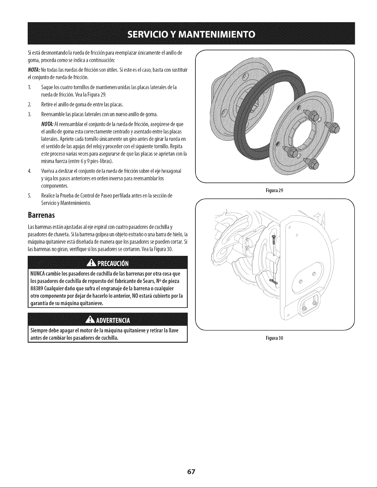
Slest_desmontandola ruedadefricci6nparareemplazart_nicamenteel anillode
goma,procedacomoseindicaacontinuaddn:
NO@:Notodaslasruedasdefrkd6n sonutiles.Siesteeselcaso,bastaconsustituir
elconjuntoderuedade frkd6n.
1. SaqueloscuatrotorniNosde mantienenunidaslasplacaslateralesdela
ruedade frkddn. Veala Figura29.
2. Retireelanillodegomadeentrelasplacas.
3. Reensamblelasplacaslateralesconun nuevoanillodegoma.
NO@:AIreensamblarel conjuntode laruedadefrkd6n, aseguresede que
elanillodegomaestacorrectamentecentradoy asentadoentrelasplacas
laterales.Aprietecadatornillo unkamenteungiroantesde girarlaruedaen
elsentidodelasagujasdel relojyprocederconel siguientetornillo.Repita
esteprocesovariasvecesparaasegurarsedequelasplacasseaprietanconla
mismafuerza(entre6y9 p[es-Nbras).
4. VuelvaadesNzarelconjuntodelaruedadefrkddn sobreelejehexagonal
y s[galospasosanterioresenordeninversoparareensamblarlos
componentes.
5. ReaNcela PruebadeControldePaseoperfiladaantesen lasecd6nde
ServkioyMantenimiento.
Barrenas
Lasbarrenasest<_najustadasalejeespiralconcuatropasadoresdecuchillay
pasadoresdechaveta.Silabarrenagolpeaunobjetoextraffoo unabarradehielo,la
m<_quinaquitanieveest<_diseffadade maneraquelospasadoressepuedencortar.Si
lasbarrenasnogiran,verifiquesilospasadoressecortaron.VealaFigura30.
blUNCAcambielospasadoresde cuchillade lasbarrenaspor otra cosaque
lospasadoresde cuchillade repuestodel fabricantede Sears,Node pieza
88389Cualquierdaffoquesufra elengranajede la barrenaocualquier
otro componentepordejar de hacerloIo anterior, NOestar<'_cubierto por la
garantia de sum_quina quitanieveo
Siempredebe apagarel motorde lam_quinaquitanievey retirarla llave
antesde cambiarlospasadoresde cuchilla.
f
Figura29
Figura30
67
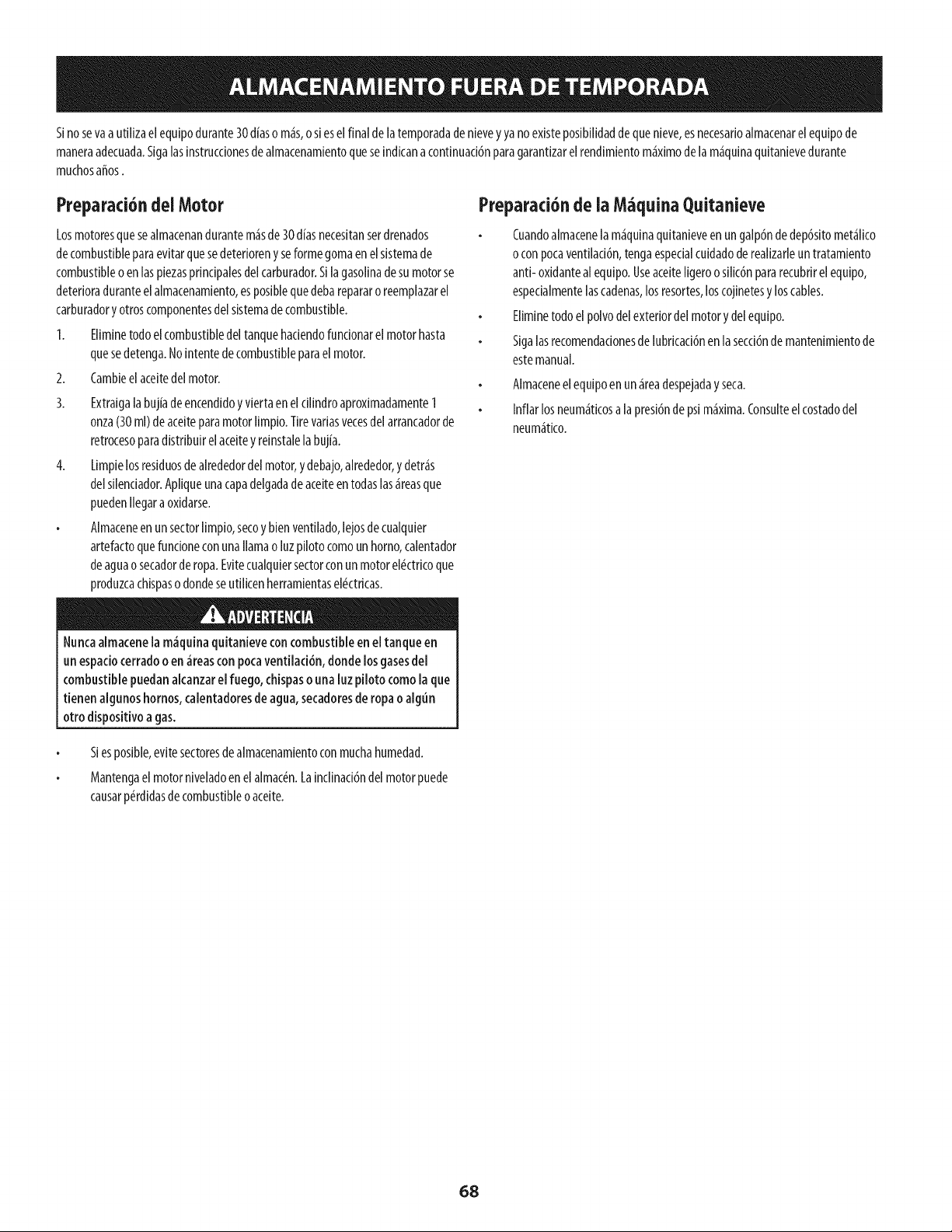
Sinosevaa uti[izaelequipodurante30d{aso m_s,o sieselfinal de[atemporadadenievey yano existeposibilidaddequenieve,esnecesarioalmacenarelequipode
maneraadecuada.Siga[asinstrucdonesde a[macenamientoqueseindicanacontinuaddnparagarantizare[rendimientom_ximode [am_quinaquitanievedurante
muchosafros.
Preparad6ndelMotor
Losmotoresquesealmacenandurantem_sde30diasnecesitanserdrenados
decombustibleparaevitarquesedeterioreny seformegomaenelsistemade
combustibleoenlas piezasprindpaiesdelcarburador.S[lagasolinadesumotorse
deterioraduranteelalmacenamiento,esposiblequedebarepararoreemplazarel
carburadory otroscomponentesdel sistemadecombustible.
1. Eliminetodoelcombustibledeltanquehadendofundonarelmotorhasta
quesedetenga.No[ntentedecombustibleparaelmotor.
2. Cambieel aceitedelmotor.
3. Extraigalabujiadeencendidoy viertaeneldlindro aproximadamente1
onza(30ml) deaceiteparamotorlimpio.Tirevariasvecesdelarrancadorde
retrocesoparadistribuirelaceitey reinstalela bujia.
4. Limpielosresiduosdealrededordelmotor,ydebajo,alrededor,y detr_s
delsilendador.Apiiqueunacapadelgadadeaceiteentodaslas_reasque
puedenIlegaraoxidarse.
Almaceneenun sectorlimp[o,secoy bienventilado,lejosdecuaiquier
artefactoquefundoneconunallamao luzpilotocomounhomo,calentador
deaguaosecadorderopa.Evitecualquiersectorconunmotorel#ctricoque
produzcacHspasodondeseutilicenherramientasel#ctricas.
e
Nuncaalmacenela m_quinaquitanieveconcombustibleen eltanque en
un espadocerradoo en _reascon pocaventiiad6n, donde losgasesde[
combustible puedanakanzar elfuego, chispasouna luzpiloto comola que
tienen algunoshornos,calentadoresde agua,secadoresde ropaoalgun
otro disposffivoagas.
Preparad6nde ia M quina Quitanieve
Cuandoalmacenelam_qulnaqultanleveen ungalp6ndedep6sitomet_lico
o conpocaventilaci6n,tengaespecialcuidadoderealizarleuntratamiento
anti- oxidanteal equipo.UseaceiteIigeroosilic6npararecubrirel equipo,
espedalmentelascadenas,losresortes,loscojinetesy loscables.
Eliminetodoelpolvodelexteriordelmotory delequipo.
Sigalasrecomendadonesdelubricaci6nenla secci6nde mantenimientode
estemanual.
Almaceneelequipoen un_readespejadayseca.
Inflarlosneum_ticosa lapresi6nde psim_xlma.Consulteelcostadodel
neum_tico.
Siesposible,evitesectoresdealmacenamientoconmuchahumedad.
Mantengaelmotorniveiadoenelaimac_n.Lainclinad6ndel motorpuede
causarp_rdidasdecombustibleoaceite.
68

69
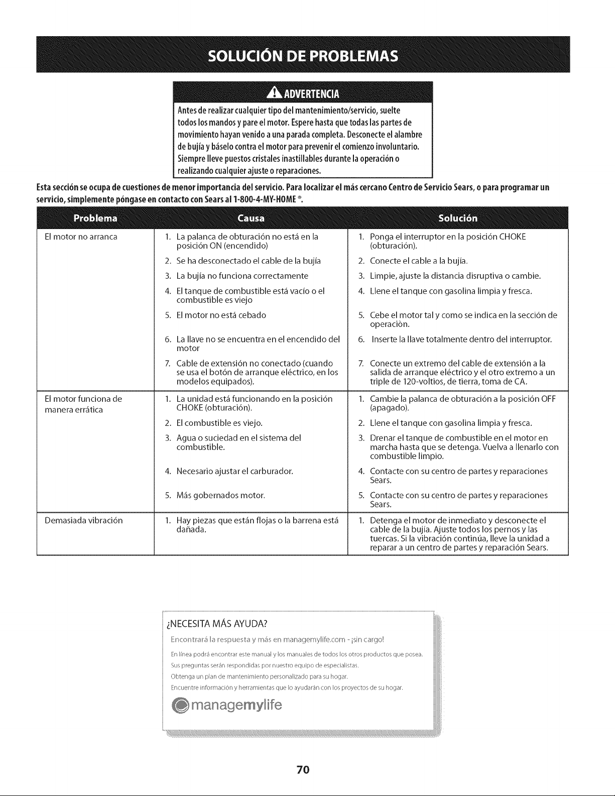
Antesde realizarcualquiertipo de[mantenimiento/servMo, sueite
todos losmandosy pare el motor.Esperehastaquetodaslaspartesde
movimiento hayanvenidoa unaparadacompleta.Desconecteel alambre
de bujia y b_selocontrael motor paraprevenir elcomienzoinvoluntario.
Siemprellevepuestoscristalesinastillablesdurante laoperad6n o
realizandocualquierajusteo reparaciones.
Estasecci6nseocupade cuestionesdemenor importanciadel servido. Para localizar el m_scercanoCentro de Servkio Sears,o para programar un
servido,simplemente p6ngaseencontacto conSearsal 1-800-4-MY-}IOME%
El motor no arranca 1. La palanca de obturaci6n no est_ en la
posici6n ON (encendido)
2. Se ha desconectado el cable de la bujia
3. La bujia no funciona correctamente
4. El tanque de combustible est_ vacio o el
combustible es viejo
5. El motor no est_ cebado
El motor funciona de
manera err_tica
Demasiada vibraci6n
6.
7.
La llave no se encuentra en el encendido del
motor
Cable de extensidn no conectado (cuando
se usa el bot6n de arranque el_ctrico, en los
1.
2.
3.
4.
5.
6.
7.
Ponga el interruptor en la posici6n CHOKE
(obturaci6n).
Conecte el cable a la bujia.
Limpie, ajuste la distancia disruptiva o cambie.
Llene el tanque con gasolina limpia y fresca.
Cebe el motor tal y como se indica en la secci6n de
operaci6n.
Inserte la Ilave totalmente dentro del interruptor.
Conecte un extremo del cable de extensi6n a la
salida de arranque el_ctrico y el otro extremo a un
modelos equipados).
I. La unidad est_ funcionando en la posici6n
CHOKE (obturaci6n).
2. El combustible es viejo.
3. Agua o suciedad en el sistema del
combustible.
4. Necesario ajustarel carburador.
5. M_s gobernados motor.
1. Hay piezas que est_n flojas o la barrena est_
dahada.
1.
2.
3.
4.
5.
1.
triple de 120-voltios, de tierra, toma de CA.
Cambie la palanca de obturaci6n a la posici6n OFF
(apagado).
Llene el tanque con gasolina limpia y fresca.
Drenar el tanque de combustible en el motor en
marcha hasta que se detenga. Vuelva a Ilenarlo con
combustible limpio.
Contacte con su centro de partes y reparaciones
Sears.
Contacte con su centro de partes y reparaciones
Sears.
Detenga el motor de inmediato y desconecte el
cable de la bujia. Ajuste todos los pernos y las
tuercas. Si la vibracidn continOa, Ileve la unidad a
reparar a un centro de partes y reparacidn Sears.
LNECESITA MA, S AYUDA?
Encont_a_5 b I_epue tay m_ en managemylife.com - isin cargo!
En Ifnea podr_ encontrar este manual y los manuales de todos los otros productos que posea,
Sus preguntas ser_n respondidas pot nuestro equipo de espedalistas,
Obtenga un plan de mantenimiento personalizado para su hogar.
Encuentre information y herramientas que Io ayudar_n con los proyectos de su hogar.
managemylife
70
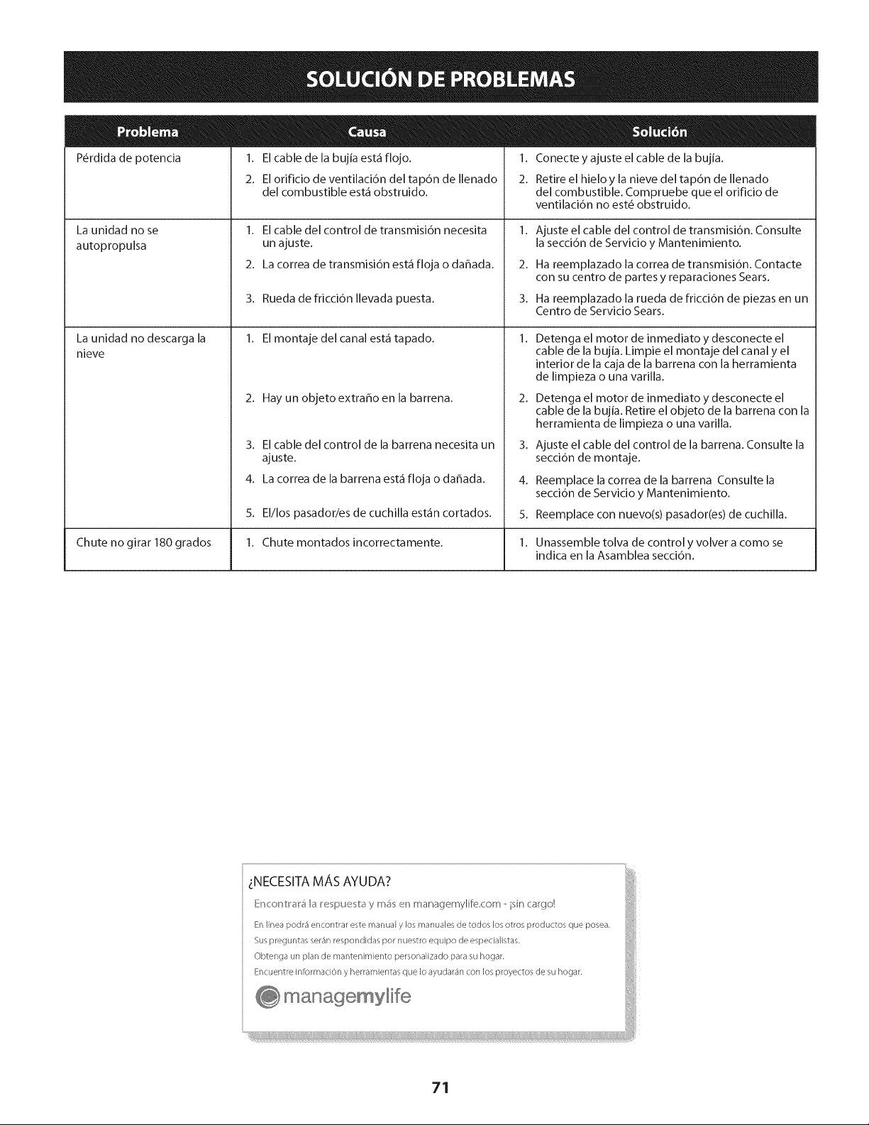
P_rdida de potencia
La unidad no se
autopropulsa
La unidad no descarga la
nieve
1. El cable de la bujia est_ flojo.
2. El orificio de ventilaci6n del tap6n de Ilenado
del combustible est_ obstruido.
1. El cable del control de transmisi6n necesita
un ajuste.
2. La correa de transmisi6n est_ floja o daflada.
3. Rueda de fricci6n Ilevada puesta.
1. El montaje del canal est_ tapado.
2. Hay un objetoextrahoen la barrena.
3. El cable del control de la barrena necesita un
ajuste.
4. La correa de la barrena est_ floja o dahada.
1. Conecte y ajuste el cable de la bujia.
2. Retire el hieloy la nieve del tap6n de Ilenado
del combustible. Compruebe que el orificio de
ventilaci6n no est6 obstruido.
2.
3.
Ajuste el cable del control de transmisi6n. Consulte
la secci6n de Servicio y Mantenimiento.
Ha reemplazado la correa de transmisi6n. Contacte
con su centro de partes y reparaciones Sears.
Ha reemplazado la rueda de fricci6n de piezas en un
Centro de Servicio Sears.
2.
3.
4.
5.
Detenga el motor de inmediato y desconecte el
cable de la bujia. Limpie el montaje del canal y el
interior de la caja de la barrena con la herramienta
de limpieza o una varilla.
Detenga el motor de inmediato y desconecte el
cable de la bujia. Retire el objeto de la barrena con la
herramienta de limpieza o una varilla.
Ajuste el cable del control de la barrena. Consulte la
secci6n de montaje.
Reemplace la correa de la barrena Consulte la
secci6n de Servicio y Mantenimiento.
5. El/los pasador/es de cuchilla est_n cortados. Reemplace con nuevo(s) pasador(es) de cuchilla.
Chute no girar 180 grados 1. Chute montados incorrectamente. 1. Unassemble tolva de control y volver a como se
indica en la Asamblea secci6n.
71

DECLARACI6NFEDERALy/o DECALiFORNiASOBREGARANTiASENELCONTROLDEEMISIONES
SUSDERECHOSY OBLIGACIONESENCUANTOA LAGARANTiA
MTD Consumer Group Inc, la Agencia de Proteccidn Medioambiental de los Estados Unidos (EPA), y para aquellos productos certificados para su
venta en el estado de California, el Departamento de los Recursos del Aire de California (CARB) se complacen en explicar la garantia que cubre
al sistema de control (ECS) de emisiones (evaporativas y/o de escape) de su equipo y motor (motor de equipos de exteriores) de encendido por
chispa para todo terreno, peque_o, de exteriores del a_o 2013 y ahos posteriores En California, los nuevos motores de equipos de exteriores
deben estar dise_ados, construidos y equipados para cumplir con las estrictas normas antipolucidn del Estado (en otros estados, los equipos
del aho 1997 y modelos posteriores deben ser estar dise_ados, construidos y equipados para cumplir con las regulaciones de motores de
encendido por chispa para todo terreno peque_os de la Agencia de Proteccidn Medioambiental de los Estados Unidos, (EPA). MTD Consumer
Group Inc. debe garantizar el sistema de control de emisiones (ECS) de su motor de equipos de exteriores por el periodo de tiempo indicado
m_is abajo, siempre y cuando no exista uso incorrecto, negligencia o mantenimiento inadecuado de dicho motor.
Su ECS puede incluir piezas tales como el carburador, el sistema de inyeccidn de combustible, el sistema de encendido, el convertidor catalitico,
los depdsitos de combustible, las lineas de combustible, los tapones de combustible, las wilvulas, contenedores, filtros, mangueras de vapor,
abrazaderas, conectores y otros componentes afines relacionados con las emisiones.
Donde exista una condicidn cubierta por la garantia, MTD Consumer Group Inc. reparar_i su motor de equipos de exteriores sin costo alguno
incluyendo el diagn6stico, las piezas y la mano de obra.
COBERTURADELA GARANTiADELFABRICANTE:
Este sistema de control de emisiones se garantiza por el t_rmino de dos a_os. Si alguna pieza relacionada con las emisiones de su motor de
equipos de exteriores es defectuosa, MTD CONSUMER GROUP INC. reparar_i o sustituir_i dicha pieza. En caso de que un componente est,1
cubierto pot m_is de dos ahos pot la garantia del equipo del fabricante, el periodo de cobertura ya no se aplicar_i.
RESPONSAI31LIDADESDELPROPIETARiOSEGUNLAGARANTiA:
En su car_icter de propietario del motor de equipos de exteriores, usted es responsable del mantenimiento requerido que se especifica en el
manual del propietario. MTD Consumer Group Inc le recomienda que conserve todos los recibos que cubren el mantenimiento de su motor, no
obstante Io cual MTD Consumer Group Inc no podr_i denegar el cumplimiento de la garantia 0nicamente pot la falta de los recibos.
Como propietario del motor de equipos de exteriores, usted debe saber que MTD Consumer Group Inc. puede denegar la cobertura de
la garantia si su motor o una pieza del mismo fallan debido a uso incorrecto, negligencia, mantenimiento indebido o a modificaciones no
aprobadas.
Usted es responsable de presentar su motor al centro de distribuci6n o servicio t_cnico de MTD Consumer Group Inc. tan pronto como
aparezca el problema. Las reparaciones cubiertas por la garantia se deben Ilevar a cabo en un lapso razonable que no exceda de 30 dias.
Si tiene alguna pregunta respecto de la cobertura de la garantia, p6ngase en contacto con el Departamento del Servicio T_cnico de MTD
Consumer Group Inc. al tel_fono 1-800-800-7310 o pot correo electr6nico en http://support.mtdproducts.com
COBERTURADELAGARANTiADEEMISIONESGENERALES:
MTD Consumer Group Inc garantiza al comprador final y a cada comprador subsiguiente que el motor de equipos de exteriores: est,1 dise_ado,
construido y equipado de modo de cumplir con todas las regulaciones aplicables y que se encuentra libre de defectos de materiales y de
fabricaci6n que pudieren causar la falla de una pieza garantizada id_ntica, en todos los aspectos materiales a la pieza descripta en la solicitud
de certificacidn de MTD Consumer Group Inc.
El periodo de garantia comienza en la fecha de entrega del motor al comprador final o en la fecha en que la m_iquina se pone en
funcionamiento pot primera vez. El periodo de garantia es de dos ahos.
Sujeto a ciertas condiciones y exclusiones que se indican a continuaci6n, la garantia de las piezas relacionadas con las emisiones es la siguiente:
1. Cualquier pieza garantizada que no est_ programada para set reemplazada como parte del mantenimiento requerido en las instrucciones
escritas suministradas se garantiza pot el periodo de garantia arriba mencionado. Si la pieza falla durante el periodo de cobertura de la
garantia, la misma ser_i reparada o reemplazada pot MTD Consumer Group Inc. de acuerdo con el p_irrafo (4) a continuaci6n. Cualquier
pieza reparada o reemplazada seg0n la garantia se garantizar_i por el resto del periodo de garantia.
2. Cualquier pieza garantizada que est_ programada solamente para inspecci6n regular en las instrucciones escritas suministradas se
garantiza pot el periodo de garantia arriba mencionado. Cualquier pieza reparada o reemplazada seg0n la garantia se garantizar_i pot el
resto del periodo.
3. Cualquier pieza garantizada que est_ programada para reemplazo seg0n el mantenimiento requerido de conformidad con las
instrucciones escritas suministradas, se garantiza pot el periodo de tiempo anterior a la primera fecha de reemplazo programada para esa
pieza. Si la pieza falla antes del primer reemplazo programado, la misma ser_i reparada o reemplazada pot MTD Consumer Group Inc. de
acuerdo con el p_irrafo (4) a continuaci6n. Cualquier pieza reparada o reemplazada bajo garantia se garantizar_i pot el resto del periodo
anterior al primer reemplazo programado puntual para esa pieza.
4. La reparaci6n o el reemplazo de cualquier pieza garantizada de conformidad con las disposiciones de la garantia que aqui se estipula se
deben realizar en un centro de garantia sin costo alguno para el propietario.
5. No obstante las disposiciones que aqui se estipulan, los servicios o reparaciones bajo garantia se suministrar_in en todos nuestros centros
de distribuci6n bajo franquicia de mantenimiento para los motores o equipos en cuesti6n.
6. Elpropietariodelmotordeequiposdeexterioresnodeber_pagareltrabajodediagndsticodirectamenteasociadoconunapieza
garantizadadefectuosaenrelaci6nconlasemisiones,siempreycuandodichotrabajodediagn6sticoserealiceenuncentrocubiertopot
lagarantia.
7. MTDConsumerGroupIncesresponsablepotdahoscausadosaotroscomponentesdemotoresoequiposderivadosdelafallabajo
garantiadecualquierpiezagarantizada.
8. Durantelatotalidaddelperiododegarantiadelmotoryequipoparatodoterrenoarribamencionado,MTDConsumerGroupInc
mantendr_unsuministro
depiezasbajogarantiasuficienteparasatisfacerlademandaesperadadetalespiezas.
9. Cualquierpiezadereemplazosepodr_usarparaelcumplimientodelmantenimientoolasreparacionesbajogarantiaysesuministraran
sincargopara
elpropietario.Dichousonoreducir_lasobligacionesdegarantiadeMTDConsumerGroupInc.
]0. Nosepodr_nusarpiezasadicionalesnimodificadasquenoest_nexentasdeacuerdoconelDepartamentodelosRecursosdelAire
(AirResourcesBoard).Elusodecualquierpiezaadicionalomodificadanoexentapotelcompradorfinalser_causaldeinvalidezdelos
reclamosbajogarantia.MTDConsumerGroupIncnotendr_responsabilidadpotlagarantiadefallasdepiezasgarantizadasquefueren
causadaspotelusodeunapiezaadicionalnoexenta
omodificada.
PI EZAS GARANTIZAi)AS:
La reparaci6n o el reemplazo de cualquier pieza garantizada que de otro modo pudiese estar cubierta por la garantia podr_ ser excluida de
tal cobertura de garantia si MTD Consumer Group Inc demuestra que el motor es objeto de uso incorrecto, negligencia o mantenimiento
inadecuado, y que tal uso incorrecto, negligencia o mantenimiento inadecuado rue causa directa de la necesidad de reparaci6n o reemplazo de
dicha pieza. No obstante Io antedicho, cualquier ajuste de un componente con un dispositivo de limitaci6n de ajuste instalado en f_brica y que
funcione adecuadamente, podr_ set cubierto pot la garantia. Adem_s,
la cobertura bajo esta garantia se extiende solo a piezas que estuvieron presentes en el motor y equipo todo terreno adquiridos.
Est_n cubiertas las siguientes piezas con garantia para emisiones (de corresponder):
1. Sistema de medici6n de combustible
Sistema de mejora para inicio en frfo (cebado suave)
Carburador y piezas internas (o sistema de inyecci6n pot combustible)
Bomba de combustible
Dep6sito de combustible
2. Sistema de inducci6n de aire
Purificador de aire
Colector de admisi6n
3. Sistema de encendido
Bujia(s) de encendido
Sistema de encendido pot magneto
4. Sistema de encendido
Convertidor catalitico
SAI (v_lvula Reed)
5. Componentes varios utilizados en el sistema anterior
Wlvulas e interruptores de vacio, temperatura, posici6n sensibles al tiempo
Conectores y montajes
6. Control evaporativo
Manguera de combustible
Abrazaderas de la manguera de combustible
Tap6n del combustible atado pot correa
Caja de carbono
Lineas de vapor
050790 Rev.A
Felicitacionespor haberrealizadouna adquisicidninteligente.EIproductoCraftsman®que haadquiridoestddise#adoy fabricado
parabrindarmuchosa#os de funcionamientoconfiable.Perocomotodoslosproductosa vecespuederequerirde reparaciones.Es
en esemomento cuandoeldisponerde un Acuerdodeproteccidnpara reparacioneslepuede ahorrardineroy problemas.
Acontinuad6nse detailan lospuntosinduidosenel Acuerdo:
[] Servido expertoprestadopornuestros10,000espedalistasenreparadonesprofesionales
[] Servido Uimitado sincargo paralaspiezasy la manodeobraentodaslasreparadonescubiertas
[] Reemplazodel producto hasta1500d6laressinoesposiblerepararel productocubierto
[] Descuentode 25%del predonormaldelservkioy delaspiezasreladonadasconel mismoquenoest_ncubiertaspor
el acuerdo;adem_s,25%del predonormaldelavefificaci6ndemantenimientopreventivo
[] Ayudar_pidapot tei_fono- IoIlamamosResolud6nR_pida- el apoyotelef6nicodeun Chamuscaal representante.
Pienseennosotroscomoelmanual"deundueffohablador."
UnavezadquiridoelAcuerdo,puedeprogramarelservidocontan s61orealizarunaIlamadatelef6nica.PuedeIlamaren
cualquiermomentodeldfao dela nocheoprogramarunservk[oen Ifnea.
ElAcuerdodeProtecd6ndeReparad6nesunacomprasinfiesgo.Siustedanulaporalgunaraz6nduranteel peffodode
garantfadeproducto,propordonaremosunreembolsoIleno.O,unreembolsoprorrateadoencualquiermomentodespu_s
delpeffododegarantfadeproductoexpira,iAdquierahoysuacuerdodeprotecd6nparareparadones[
Seaplican determinadas iimitacionesy exclusiones.Para obtener informaci6nadicionai y preciosen los
EstadosUnidosiiameai 1-800-827-6655.
El*Coverageen Canad_varia en algunos artkulos. Paradetalles llenos la llamada ChamuscaCanad_en 1-800-
361-6665.
Servidode instalad6ndeSears
Sideseasolidtarla instalad6nprofesionaldeSearsdeaparatosdom_sticos,dispositivosparaabfirportones,calentadoresde
aguay otrosartkulosdom_sticosimportantes,enlosEstadosUnidoso Canad_Ilameal 1-800-4-MY-HOME®.
74

Esta pgtginase march6 intencionadamenteen blanco.
75

Your Home
For troubleshooting, product manuals and expert advice:
managernylife
www.managemylife.com
For repair - in your home - of all major brand appliances,
lawn and garden equipment, or heating and cooling systems,
no matter who made it, no matter who sold it!
For the replacement parts, accessories and
owner's manuals that you need to do-it-yourself.
For Sears professional installation of home appliances
and items like garage door openers and water heaters.
1-800-4-MY-HOME ® (1-800-469-4663)
Call anytime, day or night (U.S.A. and Canada)
www.sears.com www.sears.ca
Our Home
For repair of carry-in items like vacuums, lawn equipment,
and electronics, call anytime for the location of your nearest
Sears Parts & Repair Service Center
1-800-488-1222 (U.S.A.) 1-800-469-4663 (Canada)
www.sears.com www.sears.ca
To purchase a protection agreement on a product serviced by Sears:
1-800-827-6655 (U.S.A.) 1-800-361-6665 (Canada)
Para pedir servicio de reparaci6n
a domicilio, y para ordenar piezas:
1-888-SU-HOGAR ®
(1-888-784-6427)
www.sears.com
Au Canada pour service en frangais:
1-800-LE-FOYER Mc
(1-800-533-6937)
www.sears.ca
® Registered Trademark / TMTrademark of KCD IP, LLC in the United States, or Sears Brands, LLC in other countries
® Marca Registrada ! TMMarca de Fabrica de KCD IP, LLC en Estados Unidos, o Sears Brands, LLC in otros paises
MCMarque de commerce ! MDMarque deposee de Sears Brands, LLC