Loading ...
Loading ...
Loading ...
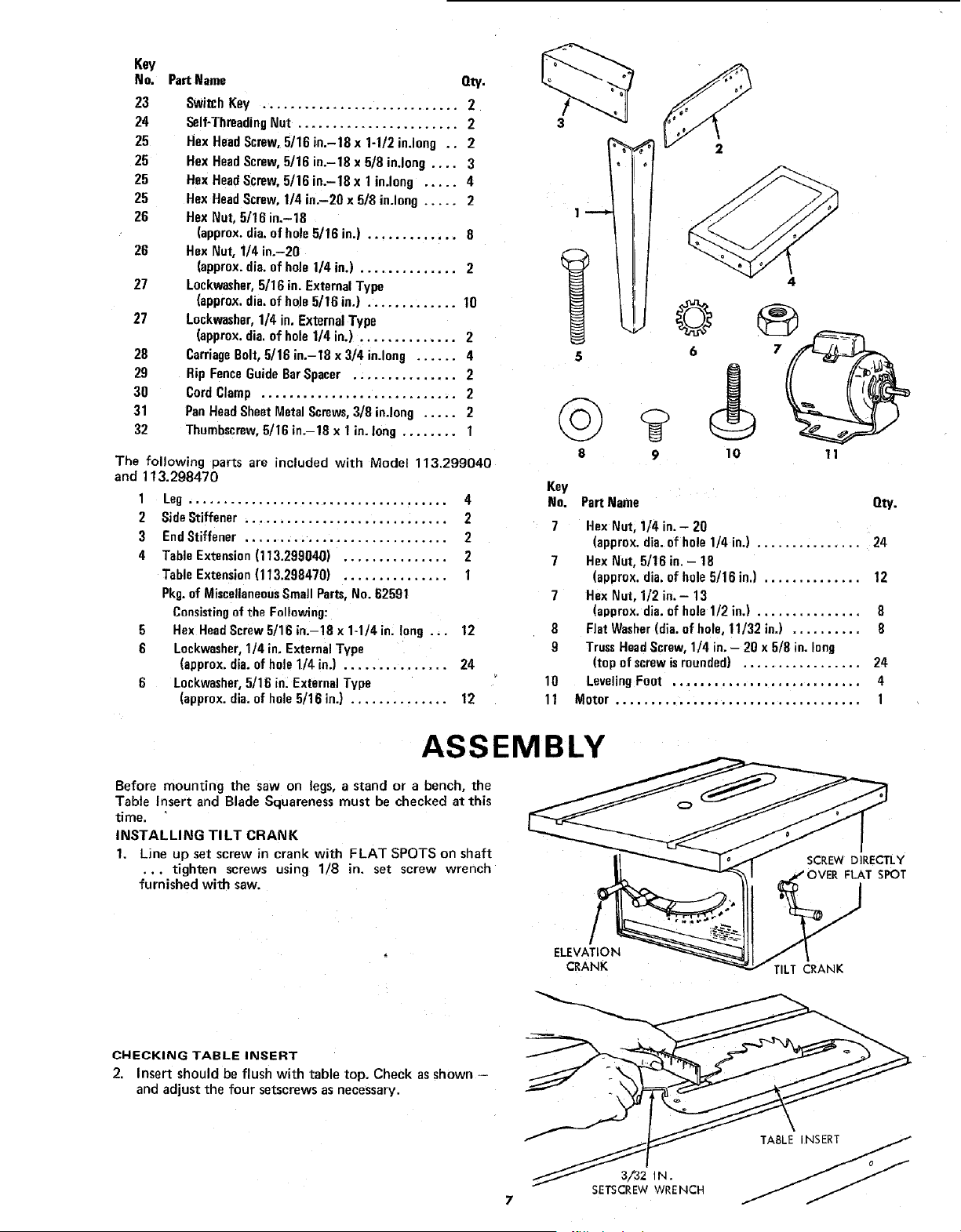
Key
No, PartName
23
24
25
25
25
25
26
26
27
27
28
29
30
31
32
_ty.
Switch Key ............................ 2
Self-ThreadingNut ....................... 2
HexHeadScrew,5/16 in.-18 x 1-1/2 in.long .. 2
HexHeadScrew,5/16 in.-18 x 5/8 inJong .... 3
Hex HeadScrew,5/16 in.-18 x 1in.long ..... 4
Hex HeadScrew,1/4 in.-20 x 5/8 in.long ..... 2
Hex Nut, 5116in.-18
(approx.dia.of hole5/16 in.) ............. 8
Hex Nut, 1/4 in.-20
(approx.dia.of hole1/4 in.) .............. 2
Lockwasher,5/16 in.ExternalType
(approx.dia.of hole5/16 in.) ............. 10
Lockwasher,1/4 in, ExternalType
(approx.dia.of holeI/4 in.) .............. 2
CarriageBolt,5/16 in.-18 x 3/4 in.long ...... 4
Rip FenceGuideBarSpacer ............... 2
CordClamp ............................ 2
PanHeadSheetMetalScrews,3/8 in.long ..... 2
Thumbscrew,5/16 in.-18 x 1in. long ........ I
The following parts are included with Model 113.299040
and 113.298470
1 Leg ..................................... 4
2 SideStiffener ............................. 2
3 EndStiffener ............................. 2
4 TableExtension(113.299040) ............... 2
TableExtension(113.298470) ............... I
Pkg.of MiscellaneousSmall Parts,No. 82591
Consistingofthe Following:
5 Hex HeadScrewS/16in.-18x1-1/4in. long ... 12
6 Lockwasher,1/4 in. ExternalType
(approx.dia.of hole1/4 in.) ............... 24
6 Loekwasher,5/16 in. ExternalType
(approx.dia.of hole5/16 in.) .............. 12
!
5
©
$
Key
No.
7
7
7
8
9
10
11
9
4
10 11
PartName Qty.
HexNut, 1/4 in. - 20
(approx.dia.of hole 1/4 in.) ............... 24
HexNut, 5/16 in.- 18
(approx.dia.of hale5/15 in.) ............. 12
HexNut, I/2 in.- 13
(approx.die.of hole 1/2 in.) ............... 8
FlatWasher(dia.of hole, 11/32 in.) .......... 8
TrussHeadScrew,1/4 in,- 20 x 5/8 in. long
(top ofscrewisrounded) ................. 24
LevelingFoot ........................... 4
Motor ................................... 1
ASSEMBLY
Before mounting the saw on legs, a stand or a bench, the
Table Insert and Blade Squareness must be checked at this
time.
INSTALLING TILT CRANK
1, Line up set screw in crank with FLAT SPOTS on shaft
... tighten screws using 1/8 in. set screw wrench
furnished with saw.
CHECKING TABLE INSERT
2. Insert should be flush with table top. Check as shown
and adjust the four setscrews as necessary.
3/32 IN.
SETSCREWWRENCH
TABLE NSERT J
Loading ...
Loading ...
Loading ...