Loading ...
Loading ...
Loading ...
OPERATING THE EZ-LINk TM SYSTEM
The EZ-Link TM system enables the use of these optional Add-Ons:
Cultivator ..................................... TBGC
Edger ........................................ TBLE
Hedge Trimmer ................................ TBAH*
Straight Shaft Trimmer ........................... TBSS
Turbo Blower .................................. TBTB
Pole Saw ..................................... TBPS*
Brushcutter ................................... TBBC*
*Do NOT use this attachment with an electric powered
product.
WARNING: When using any attachment, read
and understand that attachment's specific manual
before you begin operation. Follow all applicable
safety information.
Removing the Cutting Attachment or Add-On
1. Turn the knob counterclockwise to loosen (Fig. 16).
2. Press and hold the release button (Fig. 16).
3. While firmly holding the upper shaft housing, pull the cutting
attachment or add-on straight out of the EZ-Link TM coupler
(Fig. 17).
I_, WARNING: To avoid serious personal injury and
damage to the unit, shut the unit off before
removing or installing add-ons.
Installing the Cutting Attachment or Add-On
NOTE: Place the unit on the ground or on a work bench to
make add-on installation or removal easier.
1. Turn knob counterclockwise to loosen (Fig. 16).
I
I Release Button
EZ-Link TM Coupler _
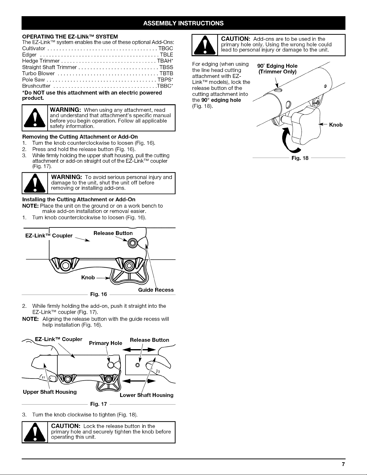
_'1 CAUTION: Add-ons are to be used in the
primary hole only. Using the wrong hole could
lead to personal injury or damage to the unit.
For edging (when using
the line head cutting
attachment with EZ-
Link TM models), lock the
release button of the
cutting attachment into
the 90 ° edging hole
(Fig. 18).
90 ° Edging Hole
(Trimmer Only)
L
Fig. 18
Knob
I
Guide Recess
Fig. 16
2. While firmly holding the add-on, push it straight into the
EZ-Link TM coupler (Fig. 17).
NOTE: Aligning the release button with the guide recess will
help installation (Fig. 16).
EZ-Link TM Coupler
Upper Shaft Housing
Release Button
Primary Hole
Lower Shaft Housing
Fig. 17
3. Turn the knob clockwise to tighten (Fig. 18).
I_, AUTION: Lock the release button in the I
primary hole and securely tighten the knob before
I
operating this unit.
Loading ...
Loading ...
Loading ...