Loading ...
Loading ...
Loading ...
–
9
–
8. BASIC WELDING
OPERATION
Note: Although this machine is medium weight and
portable take care with additional items i.e. gas bottles
etc. Do not manoeuvre over people’s heads.
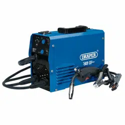
8.1 WELDING TYPE SELECTION -
SWITCH – FIG.5
5
FIG.
Note: Welding is a mix of science and art and due to the
complex principles and vast differences in parameters
(ie. Material type, position, condition etc.) That
information is well beyond the scope of this manual.
Draper Tools suggest training be obtained from a third
party or refer to a suitable reference book on the subject
additionally; nothing can beat practice using the welder
on scrap material to get a better understanding.
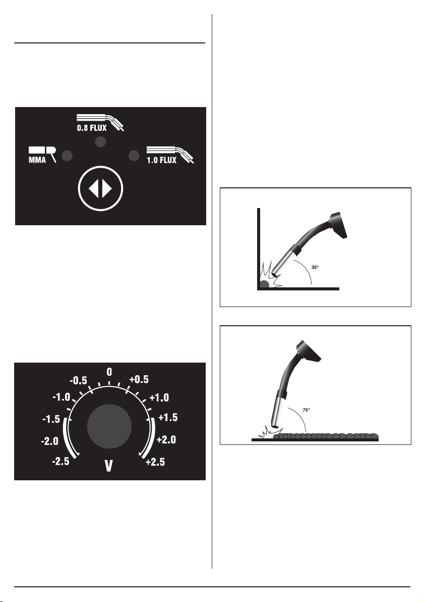
8.2 SYNERGY MIG – FIG. 6
Requires just adjust welding current, other parameters
like voltage, wire speed will automatically match.
6
FIG.
For precise welding, adjust compensation voltage.
Micro adjustment for desired welding voltage.
Position at middle is for standard welding.
8.3 MIG WELDING PRINCIPLES
– FIGS. 7 – 8
The MIG welding process allows two similar materials to
be fused together without altering the properties of the
material. The electric arc created between the electrode
(the welding wire) and the work piece produces the
required heat for turning the metal into a molten state.
The gas creates a shield around the arc and the molten
metal.
The area to be welded and the earth point must be
clean of grease, dirt, paint and rust. Clean with a wire
brush as necessary. Position the earth clamp as close
as possible to the working area and ensure a tight grip is
achieved.
Select the welding current based on the thickness of the
material. A thick piece will require a high current,
however due to the duty cycle this will effect the welding
time by significantly reducing it. A thin piece will only
require minimal heat and so the current can be less.
This will allow a longer period of welding. The position of
the torch is critical to the arc and end results.
7
FIG.
8
FIG.
The position of the welding torch is important to achieve
a good quality bead. Position the torch at approximately
35° vertically and 75° horizontally and up to 20mm
distance from the join. 20mm is the maximum that can
be achieved on the maximum setting. Ensure the gas
shroud remains clean of spatter. Likewise and more
importantly the wire feed tip must be kept clean to avoid
the wire becoming blocked or restricted.
Use of an anti-spatter spray (Draper Stock No.05709)
will help keep the end result more tidy.
Loading ...
Loading ...
Loading ...