Loading ...
Loading ...
Loading ...
–
10
–
8.4 ARC WELDING, FILLER ROD
(ELECTRODE) SELECTION – FIG. 9
The correct selection of electrode size and type will vary
for each application dependent upon material thickness,
material type, amperage and equipment, however as a
guide the figures below provide an indication.
MMA Electrode Material Thickness Amp Range
≤1.6mm 1-1.5mm ≤50A
2.0mm 1.2-3mm 45 - 75A
2.5mm 2-5mm 75 - 110A
3.25mm 4-8mm 100 - 150A
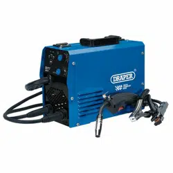
With the MMA welding process the arc created between
the work piece and the consumable electrode rod melts
the parent metal and the filler metal in a weld pool.
The electrode’s flux coating reacts during this process
and develops into a shield gas protecting the weld bead.
Part of this reaction leaves a trail of slag which solidifies
behind the weld pool protecting the weld as it cools.
The most common varieties of electrodes are cellulosic,
rutile and basic, the latter two being the most general
purpose.
Selection of the appropriate specification electrode is
important to achieve a good quality weld. Seek guidance
if unsure of selection.
9
FIG.
8.5 MMA/ARC MACHINE OPERATION
- FIG. 10
Prepare the joint(s) to be welded.
Select the electrode suitable for the application and
insert into the electrode holder (13) while pressing lever
(13.1).
With the earth clamp and electrode holder connected,
connect the machine to the power supply. The power
display will illuminate as confirmation. Set the amperage
appropriate to the selected electrode size.
Secure the earth clamp to a clean sound section of the
parent metal in the vicinity to the intended weld.
With all safety equipment in place and personal
protective clothing on begin welding.
Lower the electrode down toward the parent metal and
strike the arc.
10
FIG.
(13)
(13.1)
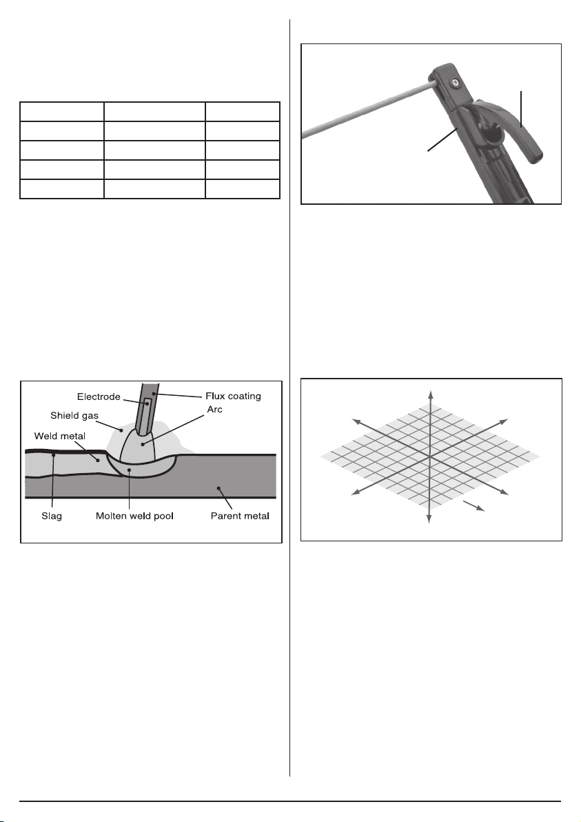
8.6 DIRECTION OF WELD – FIG. 11
Strike the initial arc perpendicular to the parent metal
before moving the electrode holder in the direction of
travel 20-30° (Z,Y axis) and tilt it 20-30° (Z,X axis).
Maintain a constant gap between the electrode tip and
the weld pool of approximately 1 to 1.5 times the
diameter of the electrode for a stable arc. This machine
is equipped with two additional features ‘Arc Force’ and
‘Anti-Stick’ to ensure smooth welding and reduce the
instances of the electrode becoming stuck to the parent
metal.
Z
-Z
-X-Y
XY
Direction
of weld
11
FIG.
Definition:
ARC FORCE
The machine will automatically create a specific
overpower when the electrode is too near, forcing it back
to help avoid the risk of sticking.
Definition:
ANTI-STICK
The machine will automatically reduce the intensity of
the current in order to aid quick and simple separation of
the electrode and parent metal.
The position of the electrode is critical to the arc and the
end result. Achieving a good weld will take practice.
For more detailed information refer to a welding book
and/or seek training on the subject.
Use of an anti-spatter spray Draper stock No.05709 will
Loading ...
Loading ...