Loading ...
Loading ...
Loading ...
6
ENGLISH
2. Install the Receiver in the Junction box using
the existing J box screws. (Fig. 4)
3. Insert the 4 AA type batteries in the battery
compartment with the correct polarity.
4. Place the slider into the cover plate.
5. Put the Receiver switch in the “OFF” position.
6. Make sure the Receiver and cover plate
words “ON”and “UP” are on the same side.
7. Align the slider with the switch on the
Receiver and couple the switch into the slider.
8. Align the screw holes.
9. Using the two (2) screws provided secure the cover plate to the Receiver.
Hearth Mounting
1. Connect the wiring harness to the back of the Receiver.
2. Install the 4 AA type batteries in the battery compartment with the correct polarity.
3. Make sure the Receiver and cover plate words “ON”and “UP” are on the same side.
4. Place the slider into the cover plate.
5. Align the slider with the switch on the Receiver and couple the switch into the slider.
6. Using the two (2) screws provided secure the cover plate to the Receiver.
Fig. 4
Fan Control Module
The FCM can be placed in a low temperature area of the appliance.
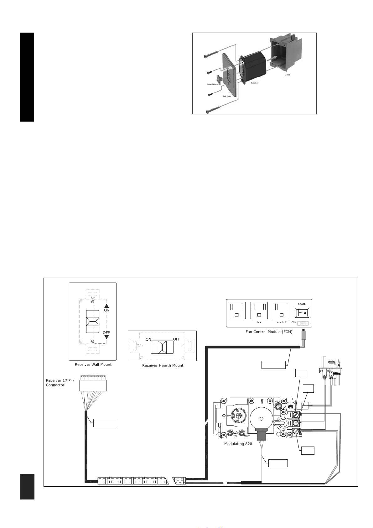
Connecting to the Gas Valve and FCM
The wiring harness for the Proflame GTM system has two wires labeled “TH” & “TPTH”. Connect
the wires to the gas valve as labeled. (TH to TH and TPTH to TPTH). Additionally there are
connectors labeled “Motor” and “COM”. Connect the “Motor” connector to the stepper motor
on the gas valve. Connect the “COM” connector to the Fan Control Module connection labeled
“COM” (Fig. 5).
REMOTE
REMOTE
TP
TH
TPTH
MOTOR
RECEIVER
FCM-COM
Green
Whi
te
Red
Black
(+)
(-)
120
V OUT
Fig. 5: Wiring diagram.
Loading ...
Loading ...
Loading ...