FOLLOW THESE STEPS WHEN BATTERY IS INSTALLED IN VEHICLE
WARNING: A SPARK NEAR THE BATTERY MAY CAUSE A BATTERY EXPLOSION. TO REDUCE THE RISK OF A SPARK NEAR THE BATTERY:
Position AC and DC cords to reduce risk of damage by hood, door, or moving engine part.
Stay clear of fan blades, belts, pulleys, and other parts that can cause injury to persons
Check polarity of battery posts. POSITIVE (POS, P, +) battery post usually has larger diameter than NEGATIVE (NEG, N, –) post.
Determine which post of battery is grounded (connected) to the chassis. If negative post is grounded to chassis (as in most vehicles), see (5). If positive post is grounded to the chassis, see (6).
For negative-grounded vehicle, connect POSITIVE (RED) clip from battery charger to POSITIVE (POS, P, +) ungrounded post of battery. Connect NEGATIVE (BLACK) clip to vehicle chassis or engine block away from battery. Do not connect clip to carburetor, fuel lines, or sheet-metal body parts. Connect to a heavy gauge metal part of the frame or engine block.
For positive-grounded vehicle, connect NEGATIVE (BLACK) clip from battery charger to NEGATIVE (NEG, N, –) ungrounded post of battery. Connect POSITIVE (RED) clip to vehicle chassis or engine block away from battery. Do not connect clip to carburetor, fuel lines, or sheet-metal body parts. Connect to a heavy gauge metal part of the frame or engine block.
When disconnecting charger, turn switches to off, disconnect AC cord, remove clip from vehicle chassis, and then remove clip from battery terminal.
See Operating Instructions for length of charge information.
FOLLOW THESE STEPS WHEN BATTERY IS OUTSIDE VEHICLE
WARNING: A SPARK NEAR THE BATTERY MAY CAUSE A BATTERY EXPLOSION. TO REDUCE THE RISK OF A SPARK NEAR THE BATTERY:
Check polarity of battery posts. POSITIVE (POS, P, +) battery post usually has a larger diameter than NEGATIVE (NEG, N, –) post.
Attach at least a 24-inch-long 6-gauge (AWG) insulated battery cable to NEGATIVE (NEG, N, –) battery post.
Connect POSITIVE (RED) charger clip to POSITIVE (POS, P, +) post of battery.
Position yourself and free end of cable as far away from battery as possible – then connect NEGATIVE (BLACK) charger clip to free end of cable.
Do not face battery when making final connection.
When disconnecting charger, always do so in reverse sequence of connecting procedure and break first connection while as far away from battery as practical.
A marine (boat) battery must be removed and charged on shore. To charge it on board requires equipment specially designed for marine use.
GROUNDING AND AC POWER CORD CONNECTIONS
1.This battery charger is for use on a nominal 120 volt circuit and has a grounded plug. The charger must be grounded, to reduce the risk of electric shock. The plug must be plugged into an outlet that is properly installed and grounded in accordance with all local codes and ordinances. The plug pins must fit the receptacle (outlet). Do not use with an ungrounded system.
2. DANGER: Never alter the AC cord or plug provided – if it does not fit the outlet, have a proper grounded outlet installed by a qualified electrician. An improper connection can result in a risk of an electric shock or electrocution.
NOTE: Pursuant to Canadian Regulations, use of an adapter plug is not allowed in Canada. Use of an adapter plug in the United States is not recommended and should not be used.
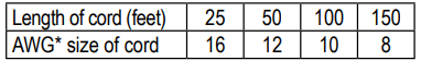
3.USING AN EXTENSION CORD The use of an extension cord is not recommended. If you must use an extension cord, follow these guidelines:
• Pins on plug of extension cord must be the same number, size, and shape as those of plug on charger.
• Ensure that the extension cord is properly wired and in good electrical condition.
• Wire size must be large enough for the AC ampere rating of charger, as specified:
*AWG-American Wire Gauge
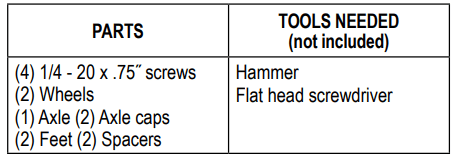
ASSEMBLY INSTRUCTIONS
1.It is important to fully asssemble your charger before use.
Remove all cord wraps and uncoil the cables prior to using the battery charger.
Follow these instructions for assembly.
2. Attach the feet: Remove the charger from the packing materials and place back down on a flat surface. Attach the feet and secure them with the four 1/4-20 x 3/4˝ screws provided.
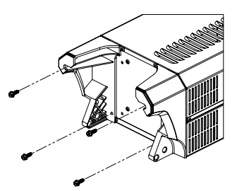
3. Assemble the wheels, spacers and axle: Slide one wheel and one spacer onto the axle, as shown. Slide the axle through the center holes of the feet. Place the charger on its other side. Slide the second spacer and the second wheel onto the axle, with recessed hubs facing out, as shown. Make sure to use the center hole. Use a hammer to install the axle caps.
4. Extend the handle from the retracted position by pulling it upward until it locks into place. (Press the small silver buttons inward, if necessary.)
CONTROL PANEL
ON/OFF SWITCH
Use this switch to select between the Charge/Maintain rate, Boost rate and the Engine Start mode.
OFF – When the switch is in this position (middle), the charger is turned off.
BOOST or CHARGE/MAINTAIN – When the switch is in this position, the Rate Selection button can be set to either the Charge/Maintain or the Boost setting.
ENGINE START – When the switch is in this position, the Rate Selection button can be set to Engine Start mode.
DIGITAL DISPLAY
The Digital Display gives a digital indication of voltage, amperage, and battery %. It always starts in Voltage mode, but can be switched to a different mode by pressing the Display button as shown below:
Boost mode: Voltage > OFF > Amperage…
Charge/Maintain mode: Voltage > OFF > Battery Percentage > Amperage…
Engine Start mode: Voltage (No Amperes or Battery Percentage Mode) If the process is stopped on any mode (by pressing the START/STOP button), the display will show “OFF”.
NOTE: When in Charge/Maintain mode, the display will automatically go into sleep mode (shut-off) after 2 minutes. To turn the display back on, press any push-button.
DISPLAY BUTTON
Use this button to set the function of the digital display to one of the following:
Battery % – The digital display shows an estimated charge percentage of the battery connected to the charger’s battery clamps, when charging.
Amps – The display shows the output current, in amps.
Voltage– The Digital Display shows the voltage at the charger battery clamps, in DC volts, while idling. The auto detection voltage, 6 or 12, will be displayed while boosting/charging.
START/STOP BUTTON
Use this button to start or stop the charging or boosting process, after the battery is properly connected and an output or rate has been selected.
RATE SELECTION BUTTON
When in Boost or Charge/Maintain mode, use this button to select one of the following rates:
Boost – For quickly adding energy to a severely discharged or large capacity battery.
Charge/Maintain– For charging small and large batteries. Not recommended for industrial applications.
When in Engine Start mode, use this button to select:
Engine Start – Provides engine start capabilities for 6V and 12V battery systems.
LED INDICATORS
LEDs light to indicate the following:
Battery % – The Digital Display shows the percentage of the battery.
Amps – The Digital Display shows the output current, in Amps.
Voltage– The Digital Display shows the battery voltage.
Charge/Maintain – The charger is in Charge/Maintain mode.
Boost – The charger is in Boost mode.
Engine Start – The charger is in Engine Start mode
Charging/Boosting– The charger has detected that a battery is connected, and is performing the selected operation.
Charged/Maintaining– The battery is fully charged and the charger is in maintain mode.
Reversed Clamps– The connections are reversed.
NOTE: See Operating Instructions for a complete description of the charger modes.
BATTERY TYPE BUTTON
Use this button to select the type of battery.
STD – Used in cars, trucks and motorcycles, these batteries have vent caps and are often marked “low maintenance” or “maintenance-free”. This type of battery is designed to deliver quick bursts of energy (such as starting engines) and has a greater plate count. The plates are thinner and have somewhat different material composition. Standard batteries should not be used for deep-cycle applications.
AGM – The Absorbed Glass Mat construction allows the electrolyte to be suspended in close proximity with the plate’s active material. In theory, this enhances both the discharge and recharge efficiency. The AGM batteries are a variant of Sealed VRLA (valve regulated lead-acid) batteries. Popular uses include high-performance engine starting, power sports, deep-cycle, solar and storage batteries.
GEL – The electrolyte in a GEL cell has a silica additive that causes it to set up or stiffen. The recharge voltages on this type of cell are lower than those for other styles of lead-acid battery. This is probably the most sensitive cell in terms of adverse reactions to overvoltage charging. Gel batteries are best used in VERY DEEP cycle application and may last a bit longer in hot weather applications. If the wrong battery charger is used on a gel cell battery, poor performance and premature failure will result.
OPERATING INSTRUCTIONS
CHARGING THE BATTERY
Keep in mind: when charging a battery, the more a battery is discharged, the faster it absorbs charge from the charger. In other words, it takes longer for the battery to absorb the last few percents of charge than the first several percents.
WARNING: When the START button is pressed in either Boost mode, Charge/Maintain mode or Engine Start mode, the clamps are energized and will spark if touched together. A spark near the battery may cause an explosion.
NOTE: A marine (boat) battery must be removed and charged on shore.
Boost or Charge/Maintain Mode
1. Place battery in a well-ventilated area.
2. Clean the battery terminals.
3. Set the switch to the OFF position.
4. Connect the battery, following the precautions listed in sections 6 and 7.
5. Connect the charger to the electrical outlet.
6. With the charger plugged in and connected to the battery of the vehicle, set the switch to the Boost/ Charge/Maintain position.
7. Select the Charge/Maintain rate and the battery type.
• If the voltage of the battery is under 12.7V, the unit will automatically switch to BOOST mode when the Start button is pressed. When the unit automatically switches to Boost mode, the Boost LED will light. When the automatic Boost mode is completed, the unit will automatically switch to the Charge/Maintain rate and complete the charge.
• If the unit doesn’t automatically switch to Boost Mode when the Start button is pressed, you can manually put the unit into the Boost mode. Press the Rate Selection button until the Boost LED lights. If the battery is properly connected the Charging/Boosting LED will light solid and the boosting process will start. Boost mode will remain energized until the Rate Selection button is pressed or the main ON/OFF switch is set to the OFF position. The unit will not automatically switch to the Charge/Maintain rate to complete the charge.
8. Press the START button.
• If the unit automatically switches to the Boost, but the Charge/Maintain rate is preferred, press the Rate Selection button (while still boosting) until the Charge/Maintain LED is illuminated.
9. To stop the charging process, press the STOP button, set the ON/OFF switch to the OFF position and disconnect the charger from the AC outlet and battery, as explained in sections 6 and 7.
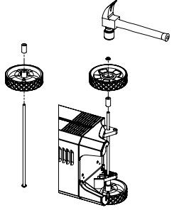
BATTERY CHARGING TIMES
Times are based on a 50% discharged battery and may change, depending on age and condition of battery.
USING THE ENGINE START FEATURE
Your battery charger can be used to jump start your car if the battery is low.
IMPORTANT: Follow the same safety instructions and precautions as when charging the battery. Wear complete eye protection and clothing protection. Charge your battery in a well-ventilated area.
WARNING: Using the Engine Start feature WITHOUT a battery installed in the vehicle will damage the vehicle’s electrical system.
NOTE: If the engine turns over but never starts, there is not a problem with the starting system; there is a problem somewhere else with the vehicle. STOP cranking the engine until the other problem has been diagnosed and corrected.
NOTE: If you have charged the battery and it still will not start your car, do not use the Engine Start feature, or it could damage the vehicle’s electrical system. Have the battery checked.
Engine Start Mode
Set the ON/OFF switch to the OFF (center) position.
Connect the charger to the battery and AC power, as explained in Follow These Steps When Battery Is Installed In Vehicle.
With the charger plugged in and connected to the battery of the vehicle, set the ON/OFF switch to the Engine Start position. If the battery is properly connected, the yellow/orange Engine Start LED will light solid and the display will show the current voltage of the battery. If the display shows “0.0”, check the battery connections.
Use the Rate Selection button to select the Engine Start rate.
Press the START button to enable the Engine Start output. The display will show “ON”.
When the Digital Display shows “Rdy”, crank the engine until it starts or 5 seconds pass. If the engine does not start within 5 seconds, wait 45 seconds before attempting to crank the engine again. NOTE: During extremely cold weather, or if the battery is under two volts, first boost the battery in Boost mode for at least several minutes before using the Engine Start feature.
NOTE: After 3 minutes in Engine Start mode, the charger will allow the charger and the battery to cool down for 180 seconds. If the engine fails to start, use the Boost mode to put energy into the battery for several minutes before attempting to crank the engine again.
7. After the engine starts, press the STOP button, set the ON/OFF switch to the OFF (center) position, unplug the AC power cord and finally disconnect the battery clamps from the vehicle, as explained in sections 6 and 7.
8. Clean and store the charger in a dry location.
ABORTED CHARGE
If charging cannot be completed normally, charging will abort. When charging aborts, the charger’s output is shut off, and the display will show and an error code. Do not continue attempting to charge this battery. Have it checked or replaced.
DESULFATION MODE
The display will show when a sulfated battery is detected, and the charger will go into desulfation mode. If the desulfation is not successful after 10 hours, the charger will go into abort mode and the display will show
COMPLETION OF CHARGE
Charge completion is indicated by the Charged/Maintaining (green) LED. When lit, the charger has switched to the maintain mode of operation.
MAINTAIN MODE (FLOAT MODE MONITORING)
When the Charged/Maintaining (green) LED is lit, the charger has started maintain mode. In this mode, the charger keeps the battery fully charged by delivering a small current when necessary. If the charger has to provide its maximum maintain current for a continuous 12 hour period, it will go into abort mode (see Aborted Charge section). This is usually caused by a drain on the battery or the battery could be bad. Make sure there are no loads on the battery. If there are, remove them. If there are none, have the battery checked or replaced.
MAINTAINING A BATTERY
This unit charges and maintains 6V and 12 volt batteries, keeping them at full charge.
NOTE: The maintain mode technology allows you to safely charge and maintain a healthy battery for extended periods of time. However, problems with the battery, electrical problems in the vehicle, improper connections or other unanticipated conditions could cause excessive current draws. As such, occasionally monitoring your battery and the charging process is required.
FAN OPERATION
It is normal for the fan to be on all of the time. Keep the area near the charger clear of obstructions to allow the fan to operate efficiently.
MAINTENANCE AND CARE
A minimal amount of care can keep your battery charger working properly for years.
• Clean the clamps each time you are finished charging. Wipe off any battery fluid that may have come in contact with the clamps to prevent corrosion.
• Occasionally cleaning the case of the charger with a soft cloth will keep the finish shiny and help prevent corrosion.
• Coil the input and output cords neatly when storing the charger. This will help prevent accidental damage to the cords and charger.
• Store the charger unplugged from the AC power outlet in an upright position.
• Store inside, in a cool, dry place. Do not store the clamps on the handle, clipped together, on or around metal, or clipped to the cables.
TROUBLESHOOTING AND ERROR CODES
Error Codes
CODE
DESCRIPTION
REASON/SOLUTION
The battery voltage is still under 10V (for a 12V battery) or 5V (for a 6V battery) after 2 hours of charging.
The battery could be bad. Have it checked or replaced.
The charger has detected a sulfated battery.
The charger will go into desulfation mode. If the desulfation is not successful after 10 hours, the charger will go into abort mode.
The charger cannot desulfate the battery.
The battery could not be desulfated; have it checked or replaced.
The battery was unable to reach the “full charge” voltage.
May be caused by trying to charge a large battery or bank of batteries on too low of a current setting. Try again with a higher current setting or have the battery checked or replaced.
The connections to the battery are reversed.
The battery is connected backwards. Unplug the charger and reverse the connections to the battery.
The charger was unable to keep the battery fully charged in maintain mode.
The battery won’t hold a charge. May be caused by a drain on the battery or the battery could be bad. Make sure there are no loads on the battery. If there are remove them. If there are none, have the battery checked or replaced.
The charger detected that the battery may be getting too hot (thermal runaway).
The charger automatically shuts the current off if it detects the battery may be getting too hot. Have the battery checked or replaced.
If you get an error code, check the connections and settings and/or replace the battery.
Troubleshooting
PROBLEM
POSSIBLE CAUSE
SOLUTION
Charger will not turn on when properly connected.
AC outlet is dead.
Check for open fuse or circuit breaker supplying AC outlet.
Poor electrical connection.
Check power cord and extension cord for loose fitting plug.
Battery is defective
Have the battery checked.
Engine start does not work.
Drawing more than the Engine Start rate.
Crank time varies with the amount of current drawn. If cranking draws more than the Engine Start rate, crank time may be less than 5 seconds.
Failure to wait 3 minutes (180 seconds) between cranks.
When the Engine Start LED blinks, wait 3 minutes of rest time before the next crank.
The charger may be overheated.
The thermal protector may have tripped and needs a little longer to reset. Make sure the charger vents are not blocked. Wait and try again.
Battery may be severely discharged.
On a severely discharged battery, use the Boost rate for 10 to 15 minutes, to help assist in cranking.
The display shows
The battery voltage is still below 10V (for a 12V battery) or 5V (for a 6V battery) after 2 hours of charging.
The battery may be defective. Make sure there are no loads on the battery. If there are, remove them. If there are none, have the battery checked or replaced.
The display shows
Desulfation was unsuccessful, after 10 hours.
The battery may be defective. Have battery checked or replaced.
The display shows
Lack of progress is detected after 12 hours in Maintain mode.
The battery won’t hold a charge. May be caused by a drain on the battery or the battery could be bad. Make sure there are no loads on the battery. If there are remove them. If there are none, have the battery checked or replaced.
 and an error code. Do not continue attempting to charge this battery. Have it checked or replaced.
 when a sulfated battery is detected, and the charger will go into desulfation mode. If the desulfation is not successful after 10 hours, the charger will go into abort mode and the display will show