If necessary to remove battery from vehicle to charge, always remove grounded terminal from battery first. Make sure all accessories in the vehicle are off, so as not to cause an arc.
Be sure area around battery is well ventilated while battery is being charged.
Clean battery terminals. Be careful to keep corrosion from coming in contact with eyes.
Add distilled water in each cell until battery acid reaches level specified by battery manufacturer. Do not overfill. For a battery without removable cell caps, such as valve regulated lead acid batteries, carefully follow manufacturer’s recharging instructions.
Study all battery manufacturer’s specific precautions while charging and recommended rates of charge.
Determine voltage of battery by referring to car owner’s manual and make sure that output voltage selector switch is set at correct voltage. If charger has adjustable charge rate, charge battery initially at lowest rate.
CHARGER LOCATION
Locate charger as far away from battery as DC cables permit.
Never place charger directly above battery being charged; gases from battery will corrode and damage charger.
Never allow battery acid to drip on charger when reading electrolyte specific gravity or filling battery.
Do not operate charger in a closed-in area or restrict ventilation in any way.
Do not set a battery on top of charger.
DC CONNECTION PRECAUTIONS
Connect and disconnect DC output clips only after setting any charger switches to “off” position and removing AC cord from electric outlet. Never allow clips to touch each other.
Attach clips to battery and chassis, as indicated in sections 6 and 7.
FOLLOW THESE STEPS WHEN BATTERY IS INSTALLED IN VEHICLE
WARNING: A SPARK NEAR THE BATTERY MAY CAUSE A BATTERY EXPLOSION. TO REDUCE THE RISK OF A SPARK NEAR THE BATTERY:
Position AC and DC cords to reduce risk of damage by hood, door, or moving engine part.
Stay clear of fan blades, belts, pulleys, and other parts that can cause injury to persons.
Check polarity of battery posts. POSITIVE (POS, P, +) battery post usually has larger diameter than NEGATIVE (NEG, N, –) post.
Determine which post of battery is grounded (connected) to the chassis. If negative post is grounded to chassis (as in most vehicles), see (6.5). If positive post is grounded to the chassis, see (6.6).
For negative-grounded vehicle, connect POSITIVE (RED) clip from battery charger to POSITIVE (POS, P, +) ungrounded post of battery. Connect NEGATIVE (BLACK) clip to vehicle chassis or engine block away from battery. Do not connect clip to carburetor, fuel lines, or sheet-metal body parts. Connect to a heavy gauge metal part of the frame or engine block.
For positive-grounded vehicle, connect NEGATIVE (BLACK) clip from battery charger to NEGATIVE (NEG, N, –) ungrounded post of battery. Connect POSITIVE (RED) clip to vehicle chassis or engine block away from battery. Do not connect clip to carburetor, fuel lines, or sheet-metal body parts. Connect to a heavy gauge metal part of the frame or engine block.
When disconnecting charger, turn switches to off, disconnect AC cord, remove clip from vehicle chassis, and then remove clip from battery terminal.
See Operating Instructions for length of charge information.
FOLLOW THESE STEPS WHEN BATTERY IS OUTSIDE VEHICLE
WARNING: A SPARK NEAR THE BATTERY MAY CAUSE A BATTERY EXPLOSION. TO REDUCE THE RISK OF A SPARK NEAR THE BATTERY:
Check polarity of battery posts. POSITIVE (POS, P, +) battery post usually has a larger diameter than NEGATIVE (NEG, N, –) post.
Attach at least a 24-inch long 6-gauge (AWG) insulated battery cable to NEGATIVE (NEG, N, –) battery post.
Connect POSITIVE (RED) charger clip to POSITIVE (POS, P, +) post of battery.
Position yourself and free end of cable as far away from battery as possible – then connect NEGATIVE (BLACK) charger clip to free end of cable.
Do not face battery when making final connection.
When disconnecting charger, always do so in reverse sequence of connecting procedure and break first connection while as far away from battery as practical.
A marine (boat) battery must be removed and charged on shore. To charge it on board requires equipment specially designed for marine use.
GROUNDING AND AC POWER CORD CONNECTIONS
This battery charger is for use on a nominal 120 volt circuit. The charger must be grounded, to reduce the risk of electric shock. The plug must be plugged into an outlet that is properly installed and grounded in accordance with all local codes and ordinances. The plug pins must fit the receptacle (outlet). Do not use with an ungrounded system.
DANGER: Never alter the AC cord or plug provided – if it does not fit the outlet, have a proper grounded outlet installed by a qualified electrician. An improper connection can result in a risk of an electric shock or electrocution.
USING AN EXTENSION CORD
The use of an extension cord is not recommended. If you must use an extension cord, follow these guidelines:
Pins on plug of extension cord must be the same number, size, and shape as those of plug on charger.
Ensure that the extension cord is properly wired and in good electrical condition.
Wire size must be large enough for the AC ampere rating of charger, as specified:
Length of cord (feet)
25
50
100
150
AWG* size of cord
16
14
14
12
*AWG-American Wire Gauge
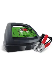
CONTROL PANEL
DIGITAL DISPLAY
The Digital Display gives digital indication of voltage and % of charge. It also gives Cool Down time remaining during Engine Start. When chosen by the Display Button, the display will show the battery Voltage or % of charge under certain conditions. First, when connected to a battery but not charging, both options are available. When charging begins, the display will automatically change to the Voltage option, and display On to indicate charging has started and then either 6 or 12, the voltage type of the battery determined by the charger. If the battery voltage is low, the display will continue to show On until the voltage type is determined. % of charge is an option only after the voltage type, 6 or 12 is determined, and also only for the Charge rate. When the battery is fully charged, indicated by the Charged/Maintaining (green) LED lit, the display and all other LEDs will turn off to conserve energy during Maintain mode.
DISPLAY BUTTON
Use this button to set the function of the digital display to one of the following:
Battery % – The Digital Display shows an estimated charge percentage of the battery connected to the charger battery clamps.
Voltage – The Digital Display shows the voltage at the charger battery clamps, in DC volts.
RATE SELECTION BUTTON
Use this button to select one of the following:
6<>2A CHARGE/MAINTAIN – For charging small and large batteries. Not recommended for industrial applications.
BOOST – For quickly adding energy to a severely discharged or large capacity battery prior to Engine Start. NOTE: Boost mode, once begun, will stay energized until the Rate Selection button is pressed.
ENGINE START – Provides additional amps for cranking an engine with a weak or run-down battery. Always use in combination with a battery.
NOTE: In general, pressing the Rate Selection button advances the selection to the next choice and lights the corresponding LED; charging will begin within a few seconds of release of the button. However, when charging has begun, pressing this button stops charging, which will cause the display to temporarily display OFF. The rate LED will turn off and the Charging (yellow/orange) LED will turn off. Then, the next button press will go back to the same rate selection that was turned off and turn on its LED. Charging will begin in a few seconds and the Charging (yellow/orange) LED will turn on. If the previous selection is not wanted, continue pressing the button to choose the preferred rate.
LED INDICATORS
CLAMPS REVERSED/BAD BATTERY (red) LED flashing: The connections are reversed. CLAMPS REVERSED/BAD BATTERY (red) LED lit: The charger has detected a problem with the battery. See Troubleshooting and Error Codes for more information.
CHARGING (yellow/orange) LED lit: The charger is charging/boosting the battery.
CHARGED/MAINTAINING (green) LED lit: The battery is fully charged and the charger is in maintain mode. NOTE: The display and all other LEDs will be off when this LED is lit, in order to conserve energy. NOTE: See Operating Instructions for a complete description of the charger modes.
BATTERY TYPE BUTTON
Use this button to select the type of battery.
STD – Used in cars, trucks and motorcycles, these batteries have vent caps and are often marked “low maintenance” or “maintenance-free”. This type of battery is designed to deliver quick bursts of energy (such as starting engines) and has a greater plate count. The plates are thinner and have somewhat different material composition. Standard batteries should not be used for deep-cycle applications.
AGM – The Absorbed Glass Mat construction allows the electrolyte to be suspended in close proximity with the plate’s active material. In theory, this enhances both the discharge and recharge efficiency. The AGM batteries are a variant of Sealed VRLA (valve regulated lead-acid) batteries. Popular uses include high-performance engine starting, power sports, deep-cycle, solar and storage batteries.
OPERATING INSTRUCTIONS
WARNING: A SPARK NEAR THE BATTERY MAY CAUSE AN EXPLOSION.
CHARGING A BATTERY IN THE VEHICLE
Turn off all the vehicle’s accessories.
Keep the hood open.
Clean the battery terminals.
Place the charger on a dry, non-flammable surface.
Lay the AC/DC cables away from any fan blades, belts, pulleys and other moving parts.
Connect the battery, following the precautions listed in sections 6 and 7.
Connect the charger to an electrical outlet.
Select the battery type.
Press the Rate Selection button until the desired option is selected (indicated by the corresponding LED turning on). Charging will then begin in a few seconds. If not pressed within 30 seconds, charging will begin automatically with the Boost rate and its LED lit. With the Charge rate selected, charging of the battery will automatically complete. Even with Charge rate selected, the charger will automatically use the Boost rate during first 10 minutes, if needed, and then switch to the Charge rate to charge the battery efficiently.
When charging is complete, indicated by Charged/Maintaining (green) LED lit, or if you are done, press Rate Selection button, disconnect the charger from the AC power, disconnect the clamp attached to vehicle’s chassis, and finally remove the clamp from battery terminal.
CHARGING A BATTERY OUTSIDE OF THE VEHICLE
Place battery in a well-ventilated area.
Clean the battery terminals.
Connect the battery, following the precautions listed in sections 6 and 7.
Connect the charger to the electrical outlet.
Select the battery type.
Press the Rate Selection button until the desired option is selected (indicated by the corresponding LED turning on). Charging will then begin in a few seconds. If not pressed within 30 seconds, charging will begin automatically with the Boost rate and its LED lit. With the Charge rate selected, charging of the battery will automatically complete. Even with Charge rate selected, the charger will automatically use the Boost rate during first 10 minutes, if needed, and then switch to the Charge rate to charge the battery efficiently.
When charging is complete, indicated by Charged/Maintaining (green) LED lit, or if you are done, press Rate Selection button, disconnect the charger from the AC power, disconnect the negative clamp, and finally the positive clamp.
A marine (boat) battery must be removed and charged on shore.
BATTERY CHARGING TIMES
Charge time will depend on battery size, as depicted in the chart below.
Times are based on a 50% discharged battery and may change, depending on age and condition of battery.
AUTOMATIC CHARGING MODE
When the 6<>2A Charge is performed, the charger switches to the maintain mode automatically after the battery is charged.
ABORTED CHARGE
If charging cannot be completed normally, charging will abort. The digital display will show FNN, where nn is an error code (see Troubleshooting for a description of the error codes). Do not continue attempting to charge this battery. Have it checked or replaced.
DESULFATION MODE
Desulfation could take 8 to 10 hours. If desulfation fails, the display will show F02, charging will abort and the Clamps Reversed/Bad Battery (red) LED will light solid.
COMPLETION OF CHARGE
Charge completion is indicated by the Charged/Maintaining (green) LED. When lit, the charger has switched to the maintain mode of operation.
MAINTAIN MODE (FLOAT MODE MONITORING)
When the Charged/Maintaining (green) LED is lit, the charger has started maintain mode. In this mode, the charger keeps the battery fully charged by delivering a small current when necessary. If the charger has to provide an excessive maintain current for a continuous 12 hour period, it will go into abort mode
(see Aborted Charge section). This is usually caused by a drain on the battery or the battery could be bad.
MAINTAINING A BATTERY
The unit charges and maintains both 6V and 12V batteries.
NOTE: The maintain mode technology allows you to safely charge and maintain a healthy battery for extended periods of time. However, problems with the battery, electrical problems in the vehicle, improper connections or other unanticipated conditions could cause excessive current draws. As such, occasionally monitoring your battery and the charging process is required.
USING THE ENGINE START FEATURE
Your battery charger can be used to jump start your car if the battery is low. Follow all safety instructions and precautions for charging your battery. Wear complete eye protection and protective clothing.
WARNING: Using the Engine Start feature WITHOUT a battery installed in the vehicle could cause damage to the vehicle’s electrical system.
NOTE: If you have charged the battery and it still will not start your car, do not use the Engine Start feature, or it could damage the vehicle’s electrical system. Have the battery checked.
With the charger unplugged from the AC outlet, connect the charger to the battery following the instructions given in Follow These Steps When Battery Is Installed In Vehicle.
Connect the charger to a live grounded 120V AC outlet.
With the charger plugged in and connected to the battery and chassis, press the Rate Selection button until the Engine Start LED is lit, and wait a few seconds for the Charging LED to light.
Crank the engine until it starts or 7 seconds pass. If the engine does not start, repeat. Do not crank during the cool down period (see below). This allows the charger and battery to cool down. NOTE: During extremely cold weather, or if the battery is under 2 volts, charge the battery for 5 minutes before cranking the engine.
If the engine fails to start, charge the battery for 5 more minutes before attempting to crank the engine again.
After the engine starts, unplug the AC power cord before disconnecting the battery clamps from the vehicle.
Clean and store the charger in a dry location.
NOTE: If the engine does turn over but never starts, there is not a problem with the starting system; there is a problem somewhere else with the vehicle. STOP cranking the engine until the other problem has been diagnosed and corrected.
ENGINE STARTING NOTES
During the starting sequence listed above, the charger is set to one of four states:
Wait for ready – The charger charges the battery for 2 minutes before the Wait for Cranking state. While waiting for ready, the digital display shows On and the engine can be cranked. For severely discharged batteries, it is not recommended to crank during this time.
Wait for cranking – The charger waits until the engine is actually being cranked before delivering the amps for engine start. While waiting for cranking, the digital display shows rdy.
Cranking – When cranking is detected, the charger will automatically deliver up to its maximum output as required by the starting system for up to 7 seconds.
Cool Down – After repeated cranking during a 3-minute ready period, the charger enters a mandatory 3 minute (180 second) cool-down state. Cranking will not be detected during this time and therefore no high output amps for engine start. The digital display indicates the remaining cool-down time in seconds. It starts at 180 and counts down to 0. After 3 minutes, the digital display will change from displaying the countdown to displaying rdy, and the charger will be back in the Wait for Cranking state described above. After 2 hours of Engine Starting, the unit will automatically exit from the charging mode, just as if the Rate Selection button had been pressed; the Charging LED will not be lit.
POWER-UP AUTO-START
This charger is equipped with an auto-start feature after application of power. If the Rate Selection button is not pressed within 30 seconds, the unit will search for a battery. If the unit detects a battery that is properly connected, the unit will set the rate to Boost (its LED will light), battery type will be set to AGM, it will automatically start the charge process, and the Charging (yellow/orange) LED will light.
FAN OPERATION
The fan will operate as needed and it is normal for the fan to sometimes operate continuously. Keep the area near the charger clear of obstructions, to allow the fan to operate efficiently.
TESTER AND CHARGER
When first turned on, the unit operates only as a tester, not as a charger. Selecting a charge rate or waiting 30 seconds (see Power-Up Auto-Start above) activates the battery charger and deactivates the tester. Pressing the Rate Selection button when charging (indicated by the Charging LED lit) will stop charging and activate the tester.
USING THE BATTERY VOLTAGE TESTER
With the charger unplugged from the AC outlet, connect the charger to the battery, following the instructions given in previous sections.
Plug the charger AC power cord into the AC outlet.
Press the Battery Type button until the correct type is indicated.
Read the voltage on the digital display. Keep in mind that this reading is only a battery voltage reading; a false surface charge may mislead you. Compare the reading to the following chart.
6V Battery
Voltage Reading
12V Battery
Voltage Reading
Battery Condition
6.4 or more
12.8 or more
Charged
6.1 to 6.3
12.2 to 12.7
Needs charging
Less than 6.1
Less than 12.2
Discharged
TESTING AFTER CHARGING
After the unit has been changed from tester to charger (by selecting a desired rate), it remains a charger. To change the battery charger back to a tester, press the Rate Selection button.
NOTE: The battery tester is only designed to test batteries. Testing a device with a rapidly changing voltage could yield unexpected or inaccurate results.
USING THE ALTERNATOR PERFORMANCE TESTER
With the charger unplugged from the AC outlet, connect the charger to the battery, following the instructions given in previous sections.
Plug the charger AC power cord into the AC outlet.
Use the Rate Selection button to select 6<>2A. After the Charging (yellow/orange) lights, press the Rate Selection button again to put the charger in tester mode and avoid the 30 second auto start.
Start the vehicle, rev the engine at 2000 rpm for 30 seconds and turn on the vehicle’s headlights or other accessories.
Read the voltage on the digital display. If you get a reading between 13.4 volts and 14.6 volts, the alternator is working properly. If the reading is less than 13.4 volts or more than 14.6 volts, refer to your vehicle’s manual or have the charging system checked by a qualified technician.
MAINTENANCE AND CARE
A minimal amount of care can keep your battery charger working properly for years.
Clean the clamps each time you are finished charging. Wipe off any battery fluid that may have come in contact with the clamps to prevent corrosion.
Occasionally cleaning the case of the charger with a soft cloth will keep the finish shiny and help prevent corrosion.
Coil the input and output cords neatly when storing the charger. This will help prevent accidental damage to the cords and charger.
Store the charger unplugged from the AC power outlet in an upright position.
Store inside, in a cool, dry place. Do not store the clamps clipped together, on or around metal, or clipped to the cables.
TROUBLESHOOTING AND ERROR CODE
Error Codes
CODE
DESCRIPTION
REASON/SOLUTION
F01
The battery voltage is still under 10V (for a 12V battery) or 5V (for a 6V battery) after 2 hours of charging.
The battery could be bad. Have it checked or replaced.
SUL
The charger has detected a sulfated battery.
The charger will go into desulfation mode. If the desulfation is not successful after 10 hours, the charger will go into abort mode.
F02
The charger cannot desulfate the battery.
The battery could not be desulfated; have it checked or replaced.
F03
The battery was unable to reach the “full charge” voltage.
May be caused by trying to charge a large battery or bank of batteries on too low of a current setting. Try again with a higher current setting or have the battery checked or replaced.
F04
The connections to the battery are reversed.
The battery is connected backwards. Unplug the charger and reverse the connections to the battery.
F05
The charger was unable to keep the battery fully charged in maintain mode.
The battery won’t hold a charge. May be caused by a drain on the battery or the battery could be bad. Make sure there are no loads on the battery. If there are remove them. If there are none, have the battery checked or replaced.
F06
The charger detected that the battery may be getting too hot (thermal runaway).
The charger automatically shuts the current off if it detects the battery may be getting too hot. Have the battery checked or replaced.
F07
The charger shut off because its internal temperature exceeds limit.
Make sure the charger does not have the side ventilation holes blocked. Move the charger out of the sun and into the shade.
F08
The battery voltage dropped too low during the maintain mode.
May be caused by a drain on the battery or the battery could be bad. Make sure there are no loads on the battery. If there are, remove them. If there are none, have the battery checked or replaced.
If you get an error code, check the connections and settings and/or replace the battery.
PROBLEM
POSSIBLE CAUSE
SOLUTION
Charger will not turn on when properly connected.
AC outlet is dead.
Poor electrical connection.
Battery is defective.
Check for open fuse or circuit breaker supplying AC outlet.
Check power cord and extension cord for loose fitting plug.
Have the battery checked.
Engine start does not work.
Drawing more than the Engine Start rate.
Failure to wait 3 minutes (180 seconds) between cranks.
The charger may be overheated.
Battery may be severely discharged.
Crank time varies with the amount of current drawn. If cranking draws more than the Engine Start rate, crank time may be less than 5 seconds.
When the cool-down countdown from 180 to 1 is displayed, wait until the display shows “rdy” for the next crank.
The thermal protector may have tripped and needs a little longer to reset. Make sure the charger vents are not blocked. Wait and try again.
On a severely discharged battery, use the Boost rate for 10 to 15 minutes, to help assist in cranking.