Loading ...
Loading ...
Loading ...
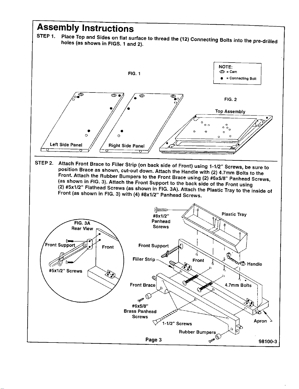
Assembly Instructions
STEP 1. Place Top and Sides on flat surface to thread the (12) Connecting Bolts into the pre-drilled
holes (as shown in FIGS. 1 and 2).
FIG, 1
NOTE:
<_ = Cam
• = Connecting Bott
Left Side Panel
Right Side Panel
FIG. 2
Top Assembly
o
(3 o
STEP 2.
Attach Front Brace to Filler Strip (on back side of Front) using 1-112" Screws, be sure to
position Brace as shown, cut-out down. Attach the Handle with (2) 4.7mm Bolts to the
Front. Attach the Rubber Bumpers to the Front Brace using (2) #6x5/8" Panhead Screws,
(as shown in FIG. 3). Attach the Front Support to the back side of the Front using
(2) #5x1/2" Flathead Screws (as shown in FIG. 3A). Attach the Plastic Tray to the inside of
Front (as shown in FIG. 3) with (4) #8x1/2" Panhead Screws.
#8x1/2"
Panhead
Screws
Plastic Tray
Front Support
Handle
Front Brace
#6x5/8"
Brass Panhead
Screws
Page 3
Screws
Rubber Bumpers
98100-3
Loading ...
Loading ...
Loading ...