
1
INDUCTION COOKTOP
OPERATING & INSTALLATION
MANUAL FOR MODEL ILD9E

OPEN 24
/
7
ILVE ACCESSORIES ONLINE SHOP
For a wide range of coee machines and other genuine
ILVE accessories at the click of a button
shop.ilve.com.au

3
you are now the proud owner of an ILVE cooking appliance.
Thank you for purchasing ILVE and welcome to the exciting
world of cooking the ILVE way.
This instruction manual has been specially created to inform
you of the full range of features your ILVE appliance has to offer
and serves as an introduction to the wonderful benefits of ILVE’s
dynamic cooking systems.
We present detailed information on each of the advanced
cooking systems built into ILVE appliances. Once you have read
this section you will be able to choose the most appropriate
settings for your appliance when cooking different types of
food.
We ask you to read the instructions in this booklet very carefully
as this will allow you to get the best results from using your
appliance. KEEP THE DOCUMENTATION OF THIS PRODUCT
FOR FUTURE REFERENCE.
Congratulations,
ILVE COOKTOPS OPERATING MANUAL

SUMMARY
SAFETY ......................................................................................................................................... 4
P
RECAUTIONS BEFORE USING
. . . . . . . . . . . . . . . . . . . . . . . . . . . . . . . . . . . . . . . . . . . . . . . . . . ...................................................... 4
U
SING THE APPLIANCE
. .. .. .. .. .. .. .. .. .. .. .. .. .. .. .. .. .. .. .. .. .. .. .. .. ................................................................. 4
P
RECAUTIONS NOT TO DAMAGE THE APPLIANCE
.............................................................................. 5
P
RECAUTIONS IN CASE OF APPLIANCE FAILURE
. . . . . . . . . . . . . . . . . . . . . . . . . . . . . . . . . . . . . . . . . . . . . . . . . . .............................. 6
O
THER PROTECTIONS
. . . . . . . . . . . . . . . . . . . . . . . . . . . . . . . . . . . . . . . . . . . . . . . . . . ................................................................. 6
DESCRIPTION OF THE APPLIANCE ........................................................................................... 7
T
ECHNICAL CHARACTERISTICS
. . . . . . . . . . . . . . . . . . . . . . . . . . . . . . . . . . . . . . . . . . . . . . . . . . ..................................................... 7
C
ONTROL PANEL
.......................................................................................................................... 7
USE OF THE APPLIANCE ............................................................................................................ 8
D
ISPLAY
...................................................................................................................................... 8
V
ENTILATION
. . . . . . . . . . . . . . . . . . . . . . . . . . . . . . . . . . . . . . . . . . . . . . . . . . .............................................................................. 8
STARTING-UP AND APPLIANCE MANAGEMENT ..................................................................... 8
B
EFORE THE FIRST USE
. . . . . . . . . . . . . . . . . . . . . . . . . . . . . . . . . . . . . . . . . . . . . . . . . . ............................................................... 8
I
NDUCTION PRINCIPLE
. . . . . . . . . . . . . . . . . . . . . . . . . . . . . . . . . . . . . . . . . . . . . . . . . . ................................................................. 8
S
ENSITIVE TOUCH
. . . . . . . . . . . . . . . . . . . . . . . . . . . . . . . . . . . . . . . . . . . . . . . . . . ....................................................................... 8
S
TARTING
-
UP
. . . . . . . . . . . . . . . . . . . . . . . . . . . . . . . . . . . . . . . . . . . . . . . . . . ............................................................................. 9
P
AN DETECTION
........................................................................................................................... 9
R
ESIDUAL HEAT
INDICATION
.......................................................................................................... 9
B
OOSTER FUNCTION
. . . . . . . . . . . . . . . . . . . . . . . . . . . . . . . . . . . . . . . . . . . . . . . . . . ................................................................... 9
C
ONTROL PANEL LOCKING
. . . . . . . . . . . . . . . . . . . . . . . . . . . . . . . . . . . . . . . . . . . . . . . . . . ......................................................... 11
A
UTOMATIC COOKING
................................................................................................................. 11
B
RIDGE
..................................................................................................................................... 12
P
AUSE FUNCTION
....................................................................................................................... 12
R
ECALL
F
UNCTION
..................................................................................................................... 12
K
EEP
W
ARM
.............................................................................................................................. 13
M
Y
F
UNCTION
. . . . . . . . . . . . . . . . . . . . . . . . . . . . . . . . . . . . . . . . . . . . . . . . . . .......................................................................... 13
COOKING ADVICES ................................................................................................................... 14
P
AN QUALITY
............................................................................................................................. 14
P
AN DIMENSION
. . . . . . . . . . . . . . . . . . . . . . . . . . . . . . . . . . . . . . . . . . . . . . . . . . ........................................................................ 14
E
XAMPLES OF COOKING POWER SETTING
. . . . . . . . . . . . . . . . . . . . . . . . . . . . . . . . . . . . . . . . . . . . . . . . . . .................................... 15
MAINTENANCE AND CLEANING .............................................................................................. 15
WHAT TO DO IN CASE OF A PROBLEM .................................................................................. 15
ENVIRONMENT PRESERVATION ............................................................................................. 17
INSTALLATION INSTRUCTIONS ............................................................................................... 18
ELECTRICAL CONNECTION ..................................................................................................... 20

4
SAFETY
Precautions before using
• Unpack all the materials.
• The installation and connecting of the appliance have to be done by
approved specialists. The manufacturer can not be responsible for
damage caused by building-in or connecting errors.
• To be used, the appliance must be well-equipped and installed in a
kitchen unit and an adapted and approved work surface.
• This domestic appliance is exclusively for the cooking of food, to
the exclusion of any other domestic, commercial or industrial use.
• Remove all labels and self-adhesives from the ceramic glass.
• Do not change or alter the appliance.
• The cooking plate can not be used as freestanding or as working
surface.
• The appliance must be grounded and connected conforming to
local standards.
• Do not use any extension cable to connect it.
• The appliance can not be used above a dishwasher or a tumble-
dryer: steam may damage the electronic appliances.
• The appliance is not intended to be operated by means of external
timer or separate remote control system.
Using the appliance
• Switch the heating zones off after using.
• Keep an eye on the cooking using grease or oils: that may quickly
ignite.
• WARNING: Unattended cooking on a hob with fat or oil can be
dangerous and may result in a fire.
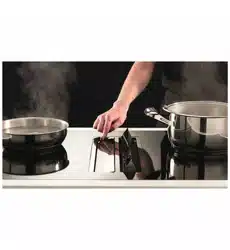
• Be careful not to burn yourself while or after using the appliance.
• Make sure no cable of any fixed or moving appliance contacts with
the glass or the hot saucepan.
• Magnetically objects (credit cards, floppy disks, calculators) should
not be placed near to the engaged appliance.

5
• Metallic objects such as knives, forks, spoons and lids should not
be placed on the hob surface since they can get hot.
• In general do not place any metallic object except heating
containers on the glass surface. In case of untimely engaging or
residual heat, this one may heat, melt or even burn.
• Never cover the appliance with a cloth or a protection sheet. This is
supposed to become very hot and catch fire.
• This appliance is not intended for use by persons (including
children) with reduced physical, sensory or mental capabilities,
or lack of experience and knowledge, unless they have been
given supervision or instruction concerning use of the appliance
by a person responsible for their safety.
• Children should be supervised to ensure that they do not play
with the appliance.
Precautions not to damage the appliance
• Raw pan bottoms or damaged saucepans (not enamelled cast iron
pots,) may damage the ceramic glass.
• Sand or other abrasive materials may damage ceramic glass.
• Avoid dropping objects, even little ones, on the vitroceramic.
• Do not hit the edges of the glass with saucepans.
• Make sure that the ventilation of the appliance works according to
the manufacturer’s instructions.
• Do not put or leave empty saucepans on the vitroceramic hobs.
• Sugar, synthetic materials or aluminium sheets must not contact
with the heating zones. These may cause breaks or other
alterations of the vitroceramic glass by cooling: switch on the
appliance and take them immediately out of the hot heating zone
(be careful: do not burn yourself).
• WARNING: Danger of fire: do not store items on the cooking
surface.
• Never place any hot container over the control panel.

6
• If a drawer is situated under the embedded appliance, make sure
the space between the content of the drawer and the inferior part of
the appliance is large enough (2 cm). This is essential to guaranty
a correct ventilation.
• Never put any inflammable object (ex. sprays) into the drawer
situated under the vitroceramic hob. The eventual cutlery drawers
must be resistant to heat.
Precautions in case of appliance failure
• If a defect is noticed, switch on the appliance and turn off the
electrical supplying.
• If the ceramic glass is cracked or fissured, you must unplug the
appliance and contact the after sales service.
• Repairing has to be done by specialists. Do not open the appliance
by yourself.
• WARNING: If the surface is cracked, switch off the appliance to
avoid the possibility of electric shock.
• If the supply cord is damaged, it must be replaced by a cable or
special set available by the manufacturer or his after sale service.
Other protections
• Note sure that the container pan is always centred on the cooking
zone. The bottom of the pan must have to cover as much as
possible the cooking zone.
• For the users of pacemaker, the magnetic field could influence its
operating. We recommend getting information to the retailer or of
the doctor.
• Do not to use aluminium or synthetic material containers: they
could melt on still hot cooking zones.
• NEVER try to extinguish a fire with water, but switch off the
appliance and then cover flame e.g. with a lid or a fire blanket.
THE USE OF EITHER PO
OR QUALITY POT OR AN
Y
INDUCTION ADAPTOR PLATE FOR NON-MAGNETIC
COOKWARE RESULTS IN A WARRANTY BREACH.
IN THIS CASE, THE MANUFACTURER CANNOT BE
HELD RESPONSIBLE FOR ANY DAMAGE CAUSED TO
THE HOB AND/OR ITS ENVIRONMENT.
7
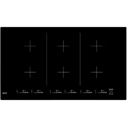
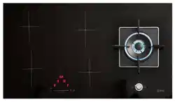
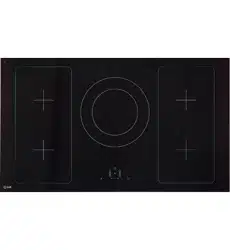
DESCRIPTION OF THE APPLIANCE
Technical characteristics
Type
Total
Power
Zones Diameter
Nominal
Power*
Booster Power*
Minimal pan
detection
ZZ1209 7400 W
Front left
Rear left
Middle
Rear right
Front right
190 x 210mm
190 x 210mm
Ø250mm
190 x 210mm
190 x 210mm
1600 W
2100 W
2300 W
2100 W
1600 W
1850 W
2300 / 3000 W
3000 W
2300 / 3000 W
1850 W
100 mm
100 mm
110 mm
100 mm
100 mm
* The given power may change according to the dimensions and material of the pan.
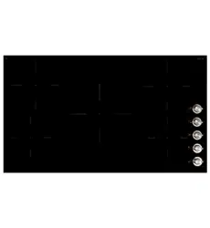
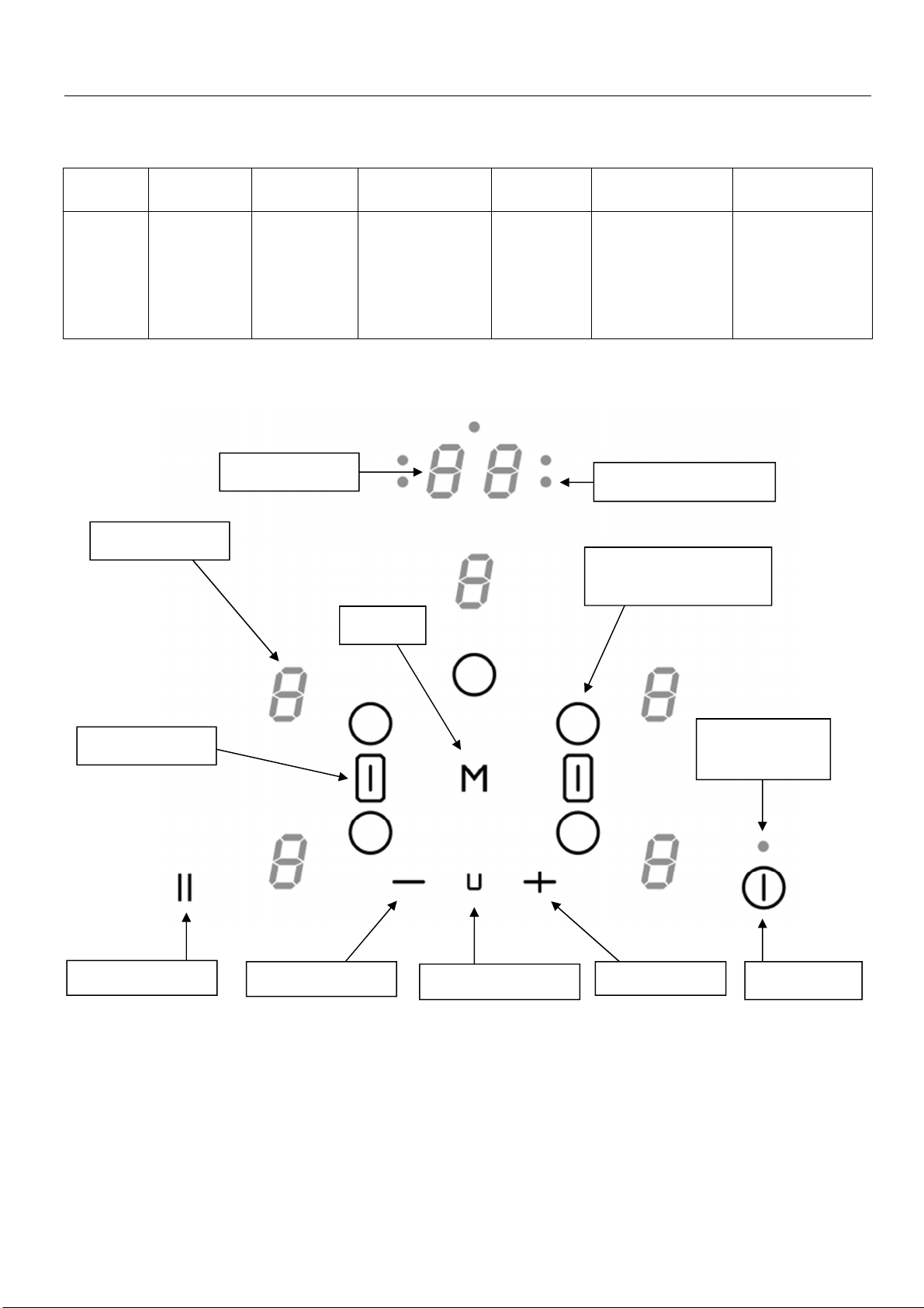
Control panel
Keep Warm key
[ - ] key
Selection and Timer
key
Power display
[ + ]
key
On/Off key
Timer display
MY key
Bridge key
Control light timer
Pause key
Control light
On/Off

8
USE OF THE APPLIANCE
Display
Display Designation Function
0 Zero The heating zone is activated.
1…9 Power level Selection of the cooking level.
U Pan detection No pan or inadequate pan.
E Error message Electronic failure.
H Residual heat The heating zone is hot.
P Booster The boosted power is activated.
Double Booster The double boosted power is activated.
L Locking Control panel locking.
II Stop & Go The hob is in pause.
U Keep warm Maintain automatically of 70°C
Bridge 2 cooking zones are combined.
Ventilation
The cooling system operates continuously. He starts when turning on the hob and speeds up
when the hob is used intensively. The cooling fan reduces its speed and stops automatically
when the electronic circuit is cooled enough.
STARTING-UP AND APPLIANCE MANAGEMENT
Before the first use
Clean your hob with a damp cloth, and then dry the surface thoroughly. Do not use detergent
which risks causing blue-tinted colour on the glass surface.
Induction principle
An induction coil is located under each heating zone. When it is engaged, it produces a variable
electromagnetic field which produces inductive currents in the ferromagnetic bottom plate of the
pan. The result is a heating-up of the pan located on the heating zone.
Of course the pan has to be adapted:
• All ferromagnetic pans are recommended (please verify it thanks a little magnet): cast iron
and steel pans, enamelled pans, stainless-steel pans with ferromagnetic bottoms…
• Are excluded: cupper, pure stainless-steel, aluminium, glass, wood, ceramic, stoneware,…
The induction heating zone adapts automatically the size of the pan. With a too small diameter
the pan doesn’t work. This diameter is varying in function of the heating zone diameter.
If the pan is not adapted to the induction hob the display will show [ U ].
Sensitive touch
Your ceramic hob is equipped with electronic controls with sensitive touch keys. When your finger
presses the key, the corresponding command is activated. This activation is validated by a
control light, a letter or a number in the display and/or a “beep” sound.
In the case of a general use press only one key at the same time.

9
Starting-up
You must first switching on the hob, then the heating zone:
• Start-up/ switch off the hob :
Action Control panel Display
To start Press key [ ] [ 0 ]
To stop Press key [ ] Nothing or [ H ]
• Start-up/ switch off a heating zone :
Action Control panel Display
Zone selection Press key [ O ] [ 0 ]
Increase power Press key [ + ] [ 1 ] to [ 9 ]
Decrease power Press key [ - ] [ 9 ] to [ 1 ]
Stop Press key [ - ] or press
simultaneously [ O ] and [ - ] [ 0 ] or [ H ]
If no action is made within 20 second the electronics returns in waiting position.
Pan detection
The pan detection ensures a perfect safety. The induction doesn’t work:
• If there is no pan on the heating zone or if this pan is not adapted to the induction. In this
case it is impossible to increase the power and the display shows [ U ]. This symbol
disappears when a pan is put on the heating zone.
• If the pan is removed from the heating zone the operation is stopped. The display shows
[ U ]. The symbol [ U ] disappears when the pan is put back to the heating zone. The
cooking continues with the power level set before.
After use, switch the heat element off: don’t let the pan detection [ U ] active.
Residual heat indication
After the switch off of a heating zone or the complete stop of the hob, the heating zones are still
hot and indicates [ H ] on the display.
The symbol [ H ] disappears when the heating zones may be touched without danger.
As far as the residual heat indicators are on light, don’t touch the heating zones and don’t put any
heat sensitive object on them. There are risks of burn and fire.
Booster function
The Booster function [ P ] and the Double Booster [ ] add a boost of power to the selected
heating zone.
If this function is activated the heating zones works during 5 minutes with an ultra high power.
The booster is foreseen for example to heat up rapidely big quantities of water, like nuddles cooking.
• Start up / Stop the booster function :
Action Control panel Display
Zone selection Press key [ O ] [ 0 ]
Increase power Press key [ + ] [ 1 ] to [ 9 ]
Start up the booster Press key [ + ] [ P ] during 5 min
Stop the booster Press key [ - ] [ 9 ]

10
• Start up / Stop the double booster function:
Action Control panel Display
Zone selection Press key [ O ] [ 0 ]
Increase power Press key [ + ] [ 1 ] to [ 9 ]
Start up the booster Press key [ + ] [ P ] during 5 min
Start up the Double Booster Press key [ + ] [ and P ]
Stop the Double Booster Press key [ - ] [ 0 ] to [ P ]
• Power management:
When it comes to the power, the cooking zones are running by pairs and cannot exceed an overall
maximum of power. If the selected heating levels for both zones exceed the maximum available
amount of power, the power management function is automatically reducing the power from one of
these zones. The display of this zone is first blinking; the level is then automatically reduced to the
highest suitable position.
Heating zone selected The other heating zone: (example: power level 9)
[ P ] is displayed [ 9 ] goes to [ 8 ] and blinks
Note: if the two left cooking zones are used at the maximal power level, the middle cooking zone
is unusable.
Timer
The timer is able to be used simultaneous with all heating zones and this with different time
settings (from 0 to 99 minutes) for each heating zone.
• Setting and modification of the cooking time :
Action Control panel Display
Zone selection Press key [ O ] [ 0 ]
Increase power Press key [ + ] [ 1 ] to [ 9 ]
To select « Timer » Press key [ O ] during 3s Timer [ 00 ] min
Decrease the time Press key [ - ] [ 00 ] wents to 99,98…
Increase the time Press key [ + ] time increase
After a few seconds the control light stops with blinking.
The time is confirmed and the cooking starts until the time reaches [ 00 ].
• To stop the cooking time :
Action Control panel Display
Zone selection Press key [ O ] [ 0 ]
To select « Timer » Press key [ O ] during 3s The remaining time
To stop the « Timer » Press key [ - ] [ 00 ] then stops
If several timers are activated repeat the process.
• Automatic stop at the end of the cooking time :
As soon as the selected cooking time is finished the timer displays blinking [ 00 ] and a sound rings.
To stop the sound and the blinking it is enough to press any key.

11
Control panel locking
To avoid modifying a setting of cooking zones , in particular with within the framework of cleaning
the control panel can be locked (with exception to the On/Off key [ ]).
• Locking :
Action Control panel Display
Start Press key [ ] [ 0 ] or [ H ]
Hob locking Press key [ II ] and keep pressed
Then press key [ M ] 3 times [ L ]
• Unlocking :
Action Control panel Display
Start Press key [ ] [ L ]
In the 5 seconds after start :
Unlocking the hob Press key [ II ] and keep pressed
T h e n p r e s s k e y [ M ] 3 t i m e s [ 0 ]
Automatic cooking
All the cooking zones are equipped with an automatic cooking device. The cooking zone starts at
full power for a certain time, and then reduces automatically its power to the pre-selected level.
• Start-up :
Action Control panel Display
Zone selection Press key [ O ] [ 0 ]
Activate the automatic cooking Press key [ II ] [ 0 ] Is blinking
with [ A ]
Power level selection Press key [ + ] until the [ 7 ] Is blinking
(For example « 7 ») power level [ 7 ] with [ A ]
• Switching off the automatic cooking :
Action Control panel Display
Zone selection Press key [ O ] [ 0 ]
Stop the automatic cooking Press key [ II ] [ 0 …9 ]
12
Bridge
This function allows to use 2 cooking zones at same time with the same features as a single
cooking zone. Booster function isn’t allowed.
Action Control panel Display
Start Press key [ ] [ 0 ] or [ H ]
Activate the bridge Press key [ ] between [ 0 ] appears on the front
the 2 cooking zones zone
[ ∏ ] on the rear zone.
Increase bridge Press key [ + ] [ 1 ] to [ 9 ]
Decrease bridge Press key [ - ] [ 9 ] to [ 1 ]
Stop the bridge Press key [ ] between [ 0 ] or [ H ] on the 2 zones
the 2 cooking zones
Pause function
This function brakes all the hob’s cooking activity and allows restarting with the same settings.
• Startup/stop the pause function :
Action Control panel Display
Engage pause press key [ ll ] displays [ II ] in the
heating zone displays
Stop the pause press key [ II ]
Then press key [ M ] [ 0…9 ] or [ P ] or [ H ]
Recall Function
After switching off the hob ( ), it is possible to recall the last settings.
• cooking stages of all cooking zones (power)
• minutes and seconds of programmed cooking zone-related timers
• Keep warm function
The recall procedure is following:
• Press the key [ ]
• Then press the key [ II ] within 6 seconds
The precedent settings are activated.

13
Keep Warm
This function allows to reach and maintain automatically a temperature of 70°C.
This will avoid liquids overflowing and fast burning at the bottom of the pan.
• To engage, to start the function « Keep warm » :
Action Control panel Display
Zone selection Press key [ O ] [ 0 ]
To engage Press key [ U ] [ U ]
To stop Press key [ U ] [ 0…9]
Press key [ + ] or [ - ] [ 0 ] or [ 1 ] or [ H ]
This function can be started independently on all the heating zones.
When the pan leaves the cooking zone of the "Keep warm" function remains active during
approximately 10 minutes.
The maximum duration of keeping warm is 2 hours.
My Function
After having set cooking level and timer value for the zone, it is possible to memorize the settings
on the same zone.
• cooking stages of cooking zone (power)
• minutes and seconds of programmed cooking zone-related timer
• Keep warm function
• Automatic cooking function
• To register a memory program for a cooking zone:
Action Control panel Display
Zone selection Press key [ O ] [ 0 ]
Set cooking level Press key [ + ] or [ - ] [ 0…9] or [ P ]
« Timer » selection Press key [ O ] during 3s Timer [ 00 ] min
Set the time Press key [ + ] or [ - ] [ 00 … 99 ]
Memorize the setting Press key [ M ] Double beep
Registering validation
If no memorizing is made within timer validation the electronics returns in cooking position.
• To activate the memory program for a cooking zone:
Action Control panel Display
Zone selection Press key [ O ] [ 0 ]
Activate the setting Press key [ M ] [ 0 … 9 ] or [ P ]
Timer [ 00 … 99 ]
Cooking zone runs with cooking level and timer value registered in memory program.
14
COOKING ADVICES
Pan quality
Adapted materials : steel, enamelled steel, cast iron, ferromagnetic stainless-steel,
aluminium with ferromagnetic bottom.
Not adapted materials :
aluminium and stainless-steel without ferromagnetic bottom,
cupper, brass, glass, ceramic, porcelain.
The manufacturers specify if their products are compatible induction.
To check if pans are compatibles :
• Put a little water in a pan placed on an induction heating zone set at level [ 9 ].This water
must heat in a few seconds.
• A magnet stucks on the bottom of the pan.
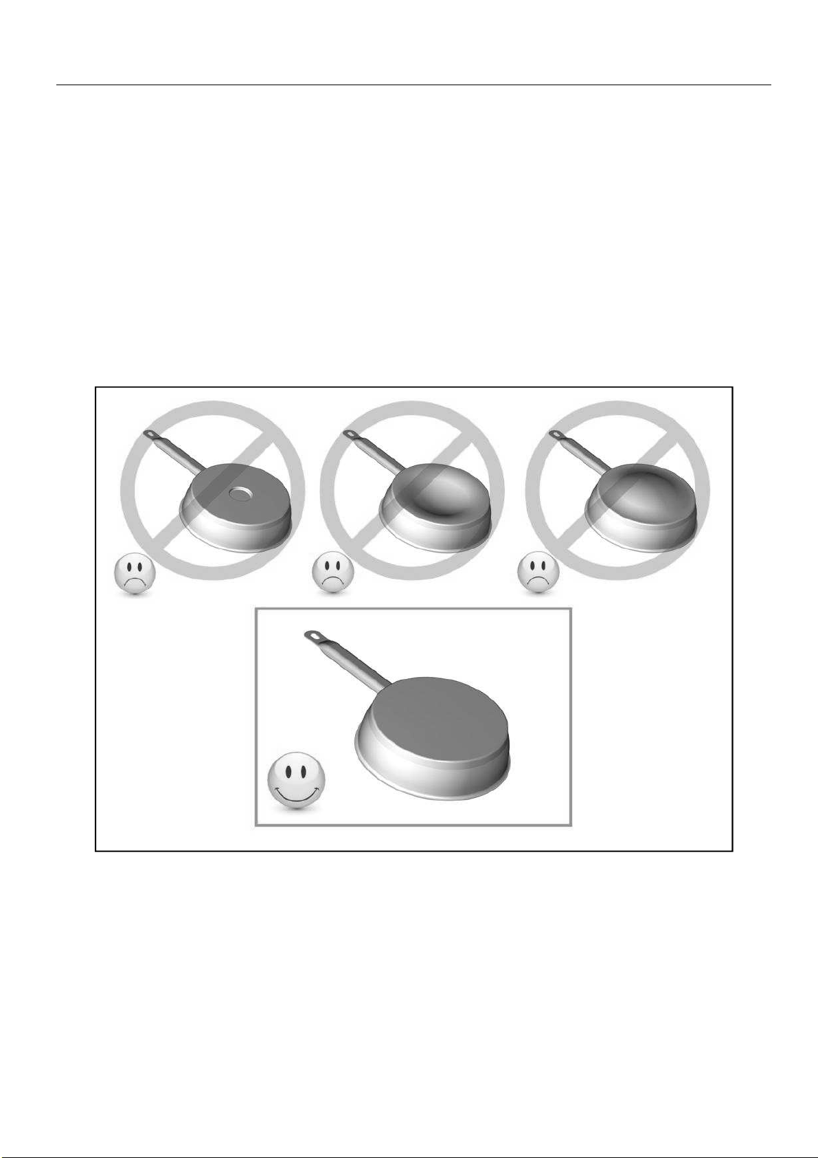
Certain pans can make noise when they are placed on an induction cooking zone. This noise
doesn’t mean any failure on the appliance and doesn’t influence the cooking operating.
Pan dimension
The cooking zones are, until a certain limit, automatically adapted to the diameter of the pan.
However the bottom of this pan must have a minimum of diameter according to the
corresponding cooking zone.
To obtain the best efficiency of your hob, please place the pan well in the centre of the cooking
zone.
15
Examples of cooking power setting
(the values below are indicative)
1 to 2 Melting
Reheating
Sauces, butter, chocolate, gelatine
Dishes prepared beforehand
2 to 3 Simmering
Defrosting
Rice, pudding, sugar syrup
Dried vegetables, fish, frozen products
3 to 4 Steam Vegetables, fish, meat
4 to 5 Water Steamed potatoes, soups, pasta,
fresh vegetables
6 to 7 Medium cooking
Simmering
Meat, lever, eggs, sausages
Goulash, roulade, tripe
7 to 8 Cooking Potatoes, fritters, wafers
9 Frying, roosting, boiling water
Steaks, omelettes, fried dishes, water
P Frying, roosting
Boiling water
scallops, steaks
Boiling significant quantities of water
MAINTENANCE AND CLEANING
Switch-off the appliance before cleaning.
Do not clean the hob if the glass is too hot because they are risk of burn.
• Remove light marks with a damp cloth with washing up liquid diluted in a little water. Then
rinse with cold water and dry the surface thoroughly.
• Highly corrosive or abrasive detergents and cleaning equipment likely to cause scratches
must be absolutely avoided.
• Do not ever use any steam-cleaner or pressure washer.
• Do not use any object that may scratch the ceramic glass.
• Ensure that the pan is dry and clean. Ensure that there are no grains of dust on your
ceramic hob or on the pan. Sliding rough saucepans will scratch the surface.
• Spillages of sugar, jam, jelly, etc. must be removed immediately. You will thus prevent the
surface being damaged.
WHAT TO DO IN CASE OF A PROBLEM
When the symbol [ E 4 ] appears :
I) The hob must be reconfigured according to the following procedure :
Before you start the procedure :
- Make sure that there is no more pot on the hob.
- Use a pan adapted to induction.
- Disconnect the appliance from the electrical network by removing the fuse or turning the
circuit breaker off.
- Reconnect the table to the electrical network.
- It is necessary to start the procedure within 2 minutes after the connection of the hob to
the electrical network.
- Do not press the [ 0/I ] key.
16
II) Cancellation of the existing configuration :
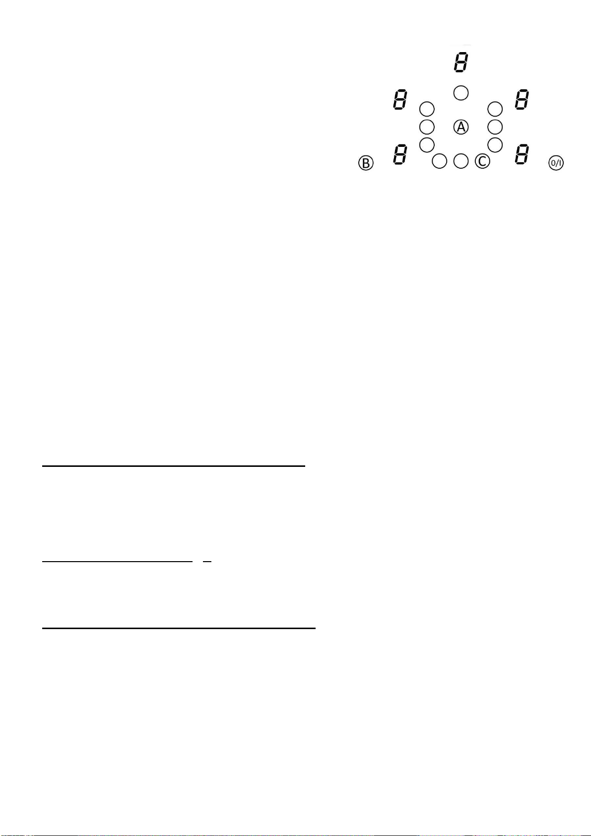
1) Press the key B and hold down.
2) With your other hand, press key A during 2s.
Released the key A.
A “bip” sound.
A double "bip" means an error occurred.
If so, start again from item 1).
3) Press the key C, always with your finger on
the key B.
A “bip” sound if manipulation is succeeded, if it
isn’t so, start again from item 1).
4) Remove your fingers from the touch control, then press again on key A during few
seconds, until blinking [ E ] symbols appear.
5) Wait until [ E ] symbols stop blinking.
6) After few seconds, [ E ] are automatically transformed in [ C ]. The existing setup has
been cancelled.
III) How to reconfigure the hob ?
1) Take a ferromagnetic pot with a minimum diameter of 16 cm.
2) Select a cooking zone by pushing on the corresponding key.
3) Place the pot on the area to be set.
4) Wait until the [ C ] display becomes a [ - ]. The selected cooking zone is now
configured.
5) Follow the same procedure for each cooking zone with a [ C ] display.
6) All the cooking zones are configured once all the displays are turned off.
Please use the same pot for the whole procedure.
Never put several pots together on the zones during the setup-process.
- If [ E 4 ] displaying remains, please call the customer care.
The hob or the cooking zone doesn’t start-up :
• The hob is badly connected on the electrical network.
• The protection fuse cut-off.
• The locking function is activated.
• The sensitive keys are covered with grease or water.
• An object is put on a key.
The control panel displays [ U ] :
• There is no pan on the cooking zone.
• The pan is not compatible with induction.
• The bottom diameter of the pan is too small.
Continuous ventilation after cutting off the hob :
• This is not a failure, the fan continuous to protect the electronic device.
• The fan cooling stops automatically.
17
One or all cooking zone cut-off :
• The safety system functioned.
• You forgot to cut-off the cooking zone for a long time.
• One or more sensitive keys are covered.
• The pan is empty and its bottom overheated.
• The hob also has an automatic reduction of power level and breaking Automatic
overheating
• The cooling can be insufficient.
It is recommended to open the kitchen furniture back wall on
the width of the cut out of the hob and plane the front cross member of kitchen furniture on
the whole width of the cut out to allow an air passage under the worktop.
The control panel displays [ L ] :
• Refer to the chapter control panel locking page.
The control panel displays [ ] or [ Er03 ] :
• An object or liquid covers the control keys. The symbol disappears as soon as the key is
released or cleaned.
The control panel displays [ E2 ] or [ EH ] :
• The hob is overheated, let it cool and then turn it on again.
The control panel displays [ E3 ] :
• The pan is not adapted, change the pan.
The control panel displays [ E5 ] :
• Defective network. Control the voltage of the electrical network.
The control panel displays [ E6 ] :
• Defective network. Control the frequency of the electrical network.
The control panel displays [ E8 ] :
• The air inlet of the ventilator is obstructed, release it.
If one of the symbols above persists, call the SAV.
ENVIRONMENT PRESERVATION
• The materials of packing are ecological and recyclable.
• The electronic appliances are composed of recyclable, and sometimes harmful materials
for the environment, but necessary to the good running and the safety of the appliance.
•
Don't throw your appliance with the household refuses
• Get in touch with the waste collection centre of your
commune that is adapted to the recycling of
the
household appliances.
18
INSTALLATION INSTRUCTIONS
The installation comes under the exclusive responsibility of specialists.
The installer is held to respect the legislation and the standards enforce in his home country.
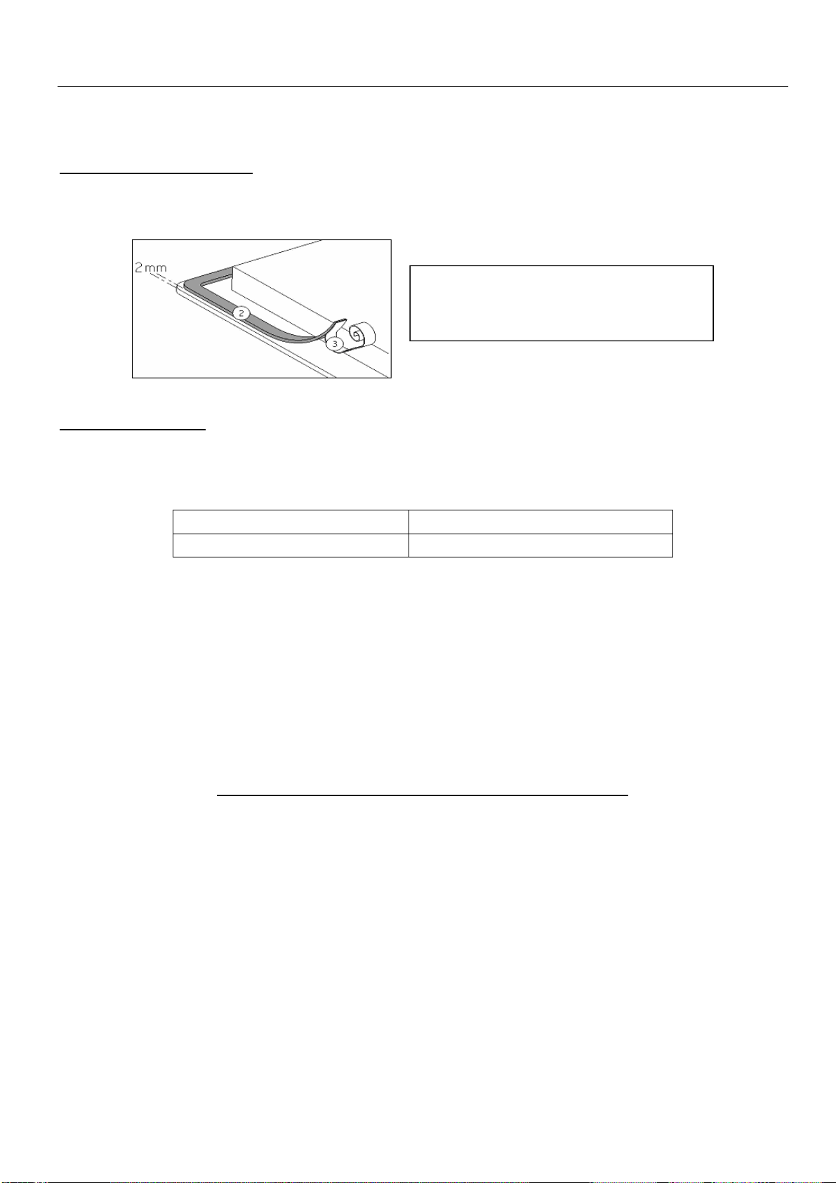
How to stick the gasket:
The gasket supplied with the hob avoids all infiltration of liquids in the cabinet.
His installation has to be done carefully, in conformity of the following drawing.
Fitting - installing:
• The cut out sizes are:
Reference Cut-size
ILD9E 810 x 490 mm
• Ensure that there is a distance of 50 mm between the hob and the wall or sides.
• The hobs are classified as “Y” class for heat protection. Ideally the hob should be installed
with plenty of space on either side. There may be a wall at the rear and tall units or a wall
at one side. On the other side, however, no unit or divider must stand higher than
the hob.
• The piece of furniture or the support in which the hob is to be fitted, as well as the edges of
furniture, the laminate coatings and the glue used to fix them, must be able to resist
temperatures of up to 100 °C.
• The mural rods of edge must be heat-resisting.
• Not to install the hob to the top of a not ventilated oven or a dishwasher.
• To guarantee under the bottom of the hob casing a space of 20 mm to ensure a good air
circulation of the electronic device.
• If a drawer is placed under the work, avoid to put into this drawer flammable objects (for
example: sprays) or not heat-resistant objects.
• Materials which are often used to make worktops expand on contact with water. To protect
the cut out edge, apply a coat of varnish or special sealant. Particular care must be given
to applying the adhesive joint supplied with the hob to prevent any leakage into the
supporting furniture. This gasket guaranties a correct seal when used in conjunction with
smooth work top surfaces.
• The safety gap between the hob and the cooker hood placed above must respect the
indications of the hood manufacturer. In case of absence of instructions respect a distance
minimum of 760 mm.
• The connection cord should be subjected, after building, with no mechanical constraint,
such for example of the fact of the drawer.
• WARNING: Use only hob guards designed by the manufacturer of the cooking appliance
or indicated by the manufacturer of the appliance in the instructions for use as suitable or
hob guards incorporated in the appliance. The use of inappropriate guards can cause
accidents.
Stick the gasket (2) two millimeters
from the external edge of the glass,
after removing the protection sheet (3).
19
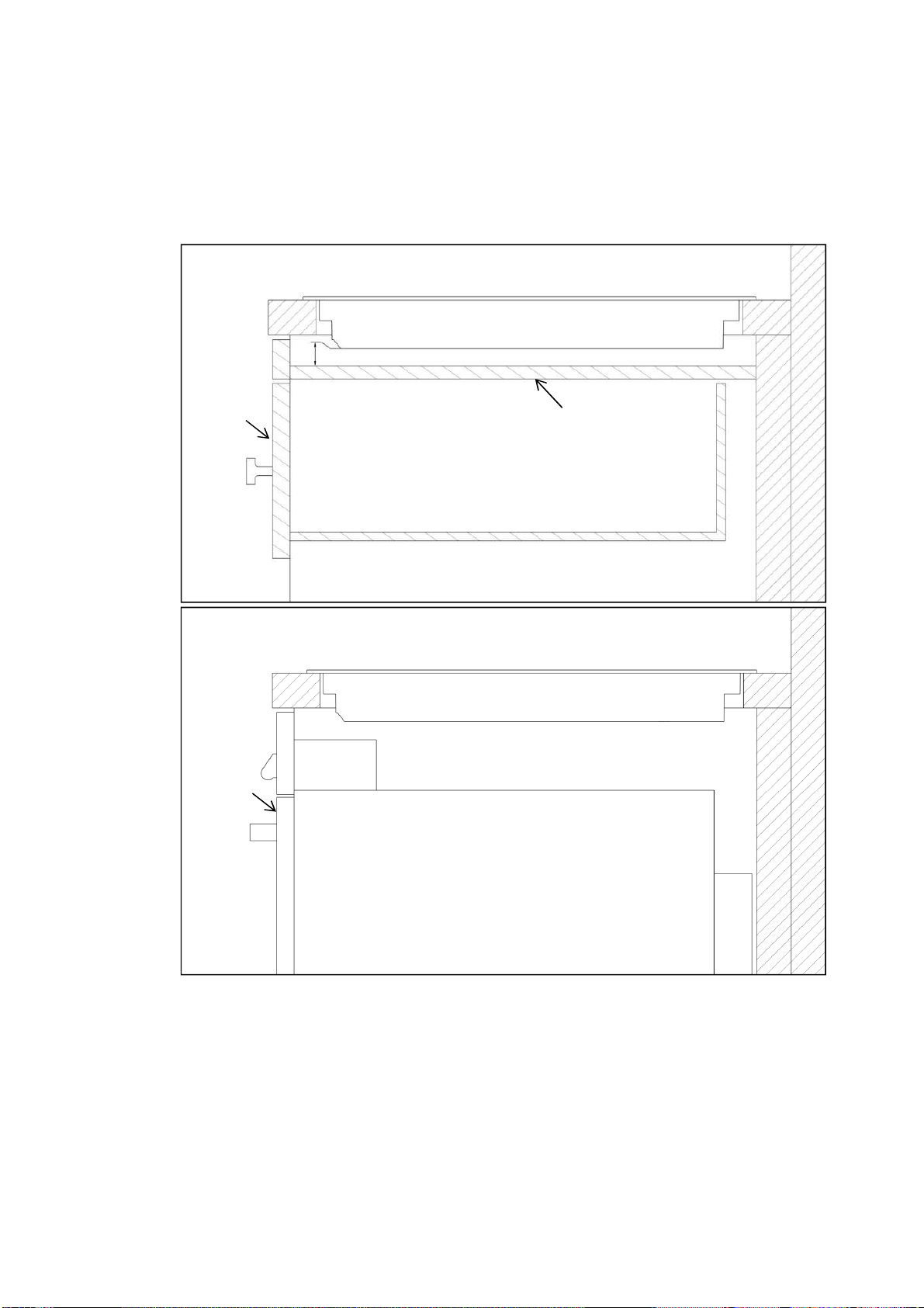
• A separation panel at least 20mm from the bottom of the cooktop must be included during
installation to prevent access to the underside of the appliance. This panel can be made of
any non-combustible rigid material. If the hob is going to be installed on the top of an oven,
precautions must be taken to guarantee an installation in accordance with current accident
prevention standards. Pay particular attention to the position of the electric cable: he must
not touch any hot parts of the oven.
Note: No barrier when
installed above an oven
Installed above an oven
Oven
Drawer
Barrier
Installed above a drawer or cupboard
20
20
ELECTRICAL CONNECTION
• The installation of this appliance and the connection to the electrical network should be
entrusted only to an electrician perfectly to the fact of the normative regulations and which
respects them scrupulously.
• Protection against the parts under tension must be ensured after the building-in.
• The data of connection necessary are on the stickers place on the hob casing near the
connection box.
• The connection to the main must be made using an earthed plug or via an omnipolar
circuit breaking device with a contact opening of at least 3 mm.
• The electrical circuit must be separated from the network by adapted devices, for example:
circuit breakers, fuses or contactors.
• If the appliance is not fitted with an accessible plug, disconnecting means must be
incorporated in the fixed installation, in accordance with the installation regulations.
• The inlet hose must be positioned so that it does not touch any of the hot parts of the hob
or even.
Caution!
This appliance has only to be connected to a network 230 V~ 50/60 Hz.
Connect always the earth wire.
Respect the connection diagram.
The connection box is located underneath at the back of the hob casing. To open the cover use a
medium screwdriver. Place it in the slits and open the cover.
* calculated with the simultaneous factor following the standard EN 60 335-2-6
Connection of the hob
Setting up the configurations:
For the various kinds of connection, use the brass bridges which are in the box next the terminal
Monophase 230V~1P+N
Put a bridge between terminal 1 and 2.
Attach the earth to the terminate “earth”, the neutral N to terminal 4, the Phase L to one of the
terminals 1 or 2.
Biphase 400V~2P+N
Attach the earth to the terminate “earth”, the neutral N to terminal 4, the Phase L1 to the terminals 1
and the Phase L2 to the terminal 2.
Caution! Frequent loosening and screwing of the screws on the connection box risks
damaging the efficiency of the tightness once screwed. It is therefore
advisable to keep screwing and unscrewing to a minimum.
Ensure that the cables are correctly inserted and tightly screwed down.
Mains Connection Cable diameter Cable Protection calibre
230V~ 50/60Hz 1 Phase + N 3 x 2.5 mm²
H 05 VV - F
H 05 RR - F
25 A *
400V~ 50/60Hz 2 Phases + N
4 x 1.5 mm²
H 05 VV - F
H 05 RR - F
16 A *
We cannot be held responsible for any incident resulting from incorrect connection or
which could arise from the use of an appliance which has not been earthed or has been
equipped with a faulty earth connection.
4
Eurolinx Pty Limited A.B.N. 50 001 473 347
trading as ILVE (“ILVE”)
Office:
48-50 Moore Street, Leichhardt N.S.W 2040
Post:
Locked Bag 3000, Annandale, N.S.W 2038
P: 1300 856 411
WARRANTY REGISTRATION
Your ongoing satisfaction with your ILVE product
is important to us. We ask that you complete the
enclosed Warranty Registration Card and return
it to us so that we have a record of the ILVE
product purchased by you, Alternitivley, you can
now register your warranty online at
http://support.eurolinx.com.au/
PRIVACY
ILVE respects your privacy and is committed
to handling your personal information in
accordance with the National Privacy Principles
and the Privacy Act 1988 (Cth). A copy of the
ILVE Privacy Policy is available at www.ilve.
com.au. ILVE will not disclose any personal
information set out in the Warranty Registration
Card (“Personal Information”) without your
consent unless required by:
1. law;
2. any ILVE related company;
3. any service provider which provide services
to ILVE or assist ILVE in providing services
(including repair and warranty services) to
customers. Our purpose in collecting the
Personal Information is to keep a record of
the ILVE product purchased by you, in order
to provide a better warranty service to you in
the unlikely event that there is a problem with
your ILVE product. ILVE may contact you at any
one or more of the addresses, email addresses
or telephone numbers set out in the Warranty
Registration Card. Please contact ILVE on 1300
694 583 should you not wish to be contacted by
ILVE.
WARRANTY
1. Warranty
ILVE warrants that each ILVE product will
remain, for a period of twenty four (24) months
computed from the date of purchase of the
ILVE product, free from defects arising in the
manufacture of the ILVE product (“Warranty”).
Except for consumer guarantees set
out in the Competition and Consumer Act 2010
(Cth) (“Act”), ILVE does not make any further
warranties or representations in relation to ILVE
products.
2. What is not Covered by the Warranty.
The Warranty does not apply if an ILVE product is
defective by a factor other than a defect arising
in the manufacture of the ILVE product, including
but not limited to:
(a) damage through misuse (including failure
to maintain, service or use with proper care),
neglect, accident or ordinary wear and tear
(including deterioration of parts and accessories
and glass breakage);
(b) use for purpose for which the ILVE product
was not sold or designed;
(c) use or installation which is not in accordance
with any specied instructions for use or
installation;
(d) use or operation after a defect has occurred or
been discovered;
(e) damage through freight, transportation or
handling in transit (other than when ILVE is
responsible);
(f) damage through exposure to chemicals, dusts,
residues, excessive voltage, heat, atmospheric
conditions or other forces or environmental
factors outside the control or ILVE;
(g) repair, modication or tampering by the
purchaser or any person other than ILVE, an
employee of ILVE or an authorised ILVE service
contractor*;
(h) use of parts, components or accessories
which have not been supplied or specically
approved by ILVE.
(i) damage to surface coatings caused by cleaning
or maintenance using products not recommended
in the ILVE product handbook provided to the
purchaser upon purchase of the ILVE product;
(j) damage to the base of an electric oven due to
items having been placed on the base of the oven
cavity or covering the base, such as aluminium
foil (this impedes the transfer of heat from the
element to the oven cavity and can result in
irreparable damage); or
(k) damages, dents or other cosmetic
imperfections not aecting the performance of the
ILVE in respect of an ILVE product purchased as a
“factory second” or from display
The Warranty does not extend to light globes
used in ILVE products.
3. Domestic Use
Each ILVE product is made for domestic use. This
Warranty may not extend to ILVE products used
for commercial purposes.
4. Time for Claim under the Warranty
You must make any claim under this Warranty
within twenty eight (28) days after the occurrence
of an event which gives rise to a claim pursuant
to the Warranty, by booking a service call on the
telephone number below.
Continued over...
WARRANTY CARD
ILVE.COM.AU
BUILT-IN COOKTOPS
ILVE COOKTOPS OPERATING MANUAL
5
5. Proof of Purchase
Customers must retain proof of purchase in order
to be eligible to make a warranty claim in respect
of an ILVE product.
6. Claiming under the Warranty
Customers will bear the cost of claiming under this
Warranty unless ILVE determines the expenses
are reasonable, in which case the customer
must claim those expenses by providing written
evidence of each expense to ILVE at the address
on the Warranty Registration Card.
7. Statutory Rights
(a) These terms and conditions do not aect your
statutory rights.
(b) The limitations on the Warranty set out in this
document do not exclude or limit the application
of the consumer guarantees set out in the Act or
any other equivalent or corresponding legislation
in the relevant jurisdiction where to do so would:
(i) contravene the law of the relevant jurisdiction;
or
(ii) cause any part of the Warranty to be void.
(c) ILVE excludes indirect or consequential loss
of any kind (including, without limitation, loss of
use of the ILVE product) and (other than expressly
provided for in these terms and conditions)
subject to all terms,
conditions and warranties implied by custom, the
general law, the Act or other statute.
(d) The liability of ILVE to you for a breach of any
express or non-excludable implied term, condition
or warranty is limited at the option of ILVE to:
(i) replacing or repairing the defective part of the
ILVE product;
(ii) paying the cost of replacing or repairing the
defective part of the ILVE product;
(iii) replacing the ILVE product; or
(iv) paying the cost of replacing the ILVE product.
(e) Our goods come with guarantees that cannot
be excluded under the Australian Consumer
Law. You are entitled to a replacement or refund
for a major failure and for compensation for any
other reasonably foreseeable loss or damage.
You are also entitled to have the goods repaired
or replaced if the goods fail to be of acceptable
quality and the failure does not amount to a
major failure.
8. Defects
Any part of an ILVE product deemed to be
defective and replaced by ILVE is the property of
ILVE. ILVE reserves the right to inspect and test
ILVE products in order to determine the extent of
any defect and the validity of a claim under the
Warranty.
*For your closest ILVE authorised service
agent go to
https://support.eurolinx.com.au/#/map/retailers
All warranty service calls must be booked
through ILVE’s Customer Care Centre on
customercare@eurolinx.com.au or
1300 85 64 11 option 1
01012018
5ILVE Operating Manual
Please complete and send to ILVE at: REPLY PAID 83617
LEICHHARDT NSW 2040
Last Name: First Name:
Address:
State: Postcode: Email:
Home Phone: Mobile:
Purchase Date: / /
(Please attach proof of purchase to validate warranty)
MODEL NUMBER
SERIAL NUMBER
(if you cannot locate the serial number please call ILVE on 1300 85 64 11)
1
2
3
4
WARRANTY REGISTRATION CARD
01032017
01012018
Warranty Card tear off
WARRANTY CARD CONTINUED
ILVE.COM.AU
BUILT-IN COOKTOPS

6
Australia National Telephone Number 1300 MYILVE (694 583) New Zealand Telephone Number 0508 458 369
ILVE showrooms are open Tuesday - Friday: 9am-5pm and Saturdays 10am-4pm. Closed on Monday & Sunday
ilve.com.au
NSW & ACT (Head Ofce)
48-50 Moore Street
Leichhardt
F 02 8569 4699
VIC & SA
1211 Toorak Road
Camberwell
F 03 9809 2155
QLD
1/42 Cavendish Road
Coorparoo
F 07 3397 0850
WA & NT
Unit 10/55 Howe Street
Osborne Park
F 08 9201 9188
TAS (Crisp Ikin)
3 Pear Avenue
Derwent Park, 7009
P 03 6272 7386
New Zealand
PO Box 11.160
Sockburn Christchurch
F 03 344 5906