EN
Fusion
INSTALLATION, OPERATING AND MAINTENANCE GUIDE
220-240V / 50Hz
220-230V / 60Hz
395.502.1

2
EN

3
EN
Index
I GENERAL 4
II WARNINGS 5
III INSTALLATION 7
III.1 PRELIMINARY INDICATIONS 7
III.1.a AIR TREATMENT 9
III.2 INSTALLATION ON UP TO 660 mm DEEP BASES 10
III.2.a INDUCTION HOB INSTALLATION 11
III.2.b EXECUTIVE DIRECTIONS 13
III.3.c ASPIRATION UNIT ASSEMBLY 16
III.3 INSTALLATION ON UP TO 840mm DEEP BASES 18
III.3.a INDUCTION HOB INSTALLATION 21
III.3.b EXECUTIVE DIRECTIONS 23
III.3.c ASPIRATION UNIT ASSEMBLY 26
III.4 INSTALLATION ON UP TO 900mm DEEP BASES 28
III.4.a INDUCTION HOB INSTALLATION 29
III.4.b EXECUTIVE DIRECTIONS 31
III.4.c ASPIRATION UNIT ASSEMBLY 34
III.5 INSTALLATION ON BASES DEEP MORE THAN 900mm 36
III.5.a INDUCTION HOB INSTALLATION 39
III.5.b EXECUTIVE DIRECTIONS 41
III.5.c ASPIRATION UNIT ASSEMBLY 44
III.6 ELECTRICAL CONNECTION 46
IV OPERATION 49
V.1 INDUCTION HOB TECHNICAL FEATURES 49
V.2 APPROPRIATE POTS FOR INDUCTION 50
V.3 INDUCTION HOB OPERATION 51
V.4 COOKER HOOD OPERATION 63
V CLEANING AND MAINTENANCE 68
VI.1 INDUCTION HOB CLEANING 68
VI.2 COOKER HOOD CLEANING 70
VI TROUBLESHOOTING GUIDE 72
VII DISCONTINUATION, DISASSEMBLY AND WASTE DISPOSAL 74

4
EN
I GENERAL
This guide is intended for the consumer and describes the appliance and its use. This guide
is an integral part of the appliance itself and has to be retained with the appliance and
ALWAYS accompany it, even in case of its assignment to another owner or user or in case
the cooker hood is moved to another installation plant.
The aspiration system is composed by two appliances:
An induction hob;
An integrated cooker hood.
The two appliances are electrically and functionally independent and for this reason there
are two separated serial numbers and two Energy Labels.
Safety Warnings required for FUSION
• Metallic objects such as knives, forks, spoons and lids should not be
placed on the hotplate since they can get hot
• CAUTION – The cooking process has to be supervised. A short term
cooking process has to be supervised continuously.
• There is a risk of fire if cleaning is not carried out in accordance with the
instructions.
• Warning: Failure to install the screws or fixing devices in accordance
with the instructions may result in an electrical hazard.
The Manufacturer strives for continuous improvements.
For this reason, the text and illustrations in this guide may change without notice.
5
EN
II WARNINGS
ATTENTION: This appliance has not been designed for gas hobs.
• This appliance is manufactured according to the safety standards in force;
• The using of this appliance must not be other than the one it has been designed for, this means as
a domestic induction hob with integrated aspiration for cooking;
• The manufacturer does not accept any liability for damages caused by people, animals or things, by
installation and maintenance mistakes or by any illegitimate use.
Caution! Unattended cooking with fat or oil can be dangerous and
may result in fire. Be sure having the preparation of such food (fries)
under constant control.
Caution! Fire hazard: do not store items on the cooking surfaces.
Caution! Never try to extinguish a fire with water, but switch off the
appliance and then cover flame e.g. with a lid or a fire blanket.
Caution! If the surface is cracked, switch off the appliance to avoid
the possibility of electric shock.
Caution! Before any cleaning or maintenance operation or in case of
storms, disconnect the appliance from the main power supply
(fig.2.1) or disconnect the plug (fig.2.2).
• Warning! Be careful not to drop objects or crockery on the glass surface. Even light objects (e.g. a
salt shaker) can crack or damage the ceramic plate.
• Warning! While the induction hob is active, even the aspiration parts adjacent to the induction hob
may become hot.
• There is a possibility of fire if the cleaning operations are not carried out as indicated in the
instructions.
• The appliance and its accessible parts become hot during use. Care should be taken to avoid touching
heating elements. Children less than 8 years of age shall be kept away unless continuously
supervised;
• Prevent the children to hang around the appliance and warn them properly against the danger of
burns;
Fig. 2.1
Fig. 2.2
6
EN
• This appliance can be used by children aged from 8 years and above, and persons with reduced
physical, sensory or mental capabilities or lack of experience and knowledge if they have been given
supervision or instruction concerning use of the appliance in a safe way and understand the hazards
involved;
• Children shall not play with the appliance;
• Cleaning and maintenance shall not be made by children without supervision;
• Don’t use high-pressure steam cleaner or hot steam to clean the appliance;
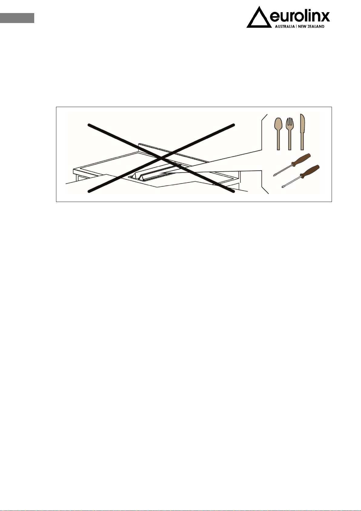
• It is forbidden to introduce any object in the aspiration flaps and air grids (fig.2.3).
• The appliance cannot be activated by external timers or remote controls systems;
• Do not use the appliance for room heating;
• If there is a wall power outlet located near the appliance and another appliance is plugged into it,
make sure the power cord does not come into contact with the hot cooking zones;
• Do not store any temperature-sensitive objects, materials, or substances underneath the appliance,
e.g. detergents, sprays, etc.
• In case of a failure of the appliance, immediately disconnect the appliance from the power mains
and contact the service center;
• Connect the appliance to a permanent connection;
• Don't connect the appliance to the power supply with an extension cable or multiple sockets,
because they don't assure a sufficient safety (e.g. overheating risk of multiple sockets);
• The appliance may be built-in and connected to the power supply only by a Qualified Technician;
• It is forbidden to pull, disconnect, twist the electrical wiring out of the appliance even if it is
disconnected from the power supply;
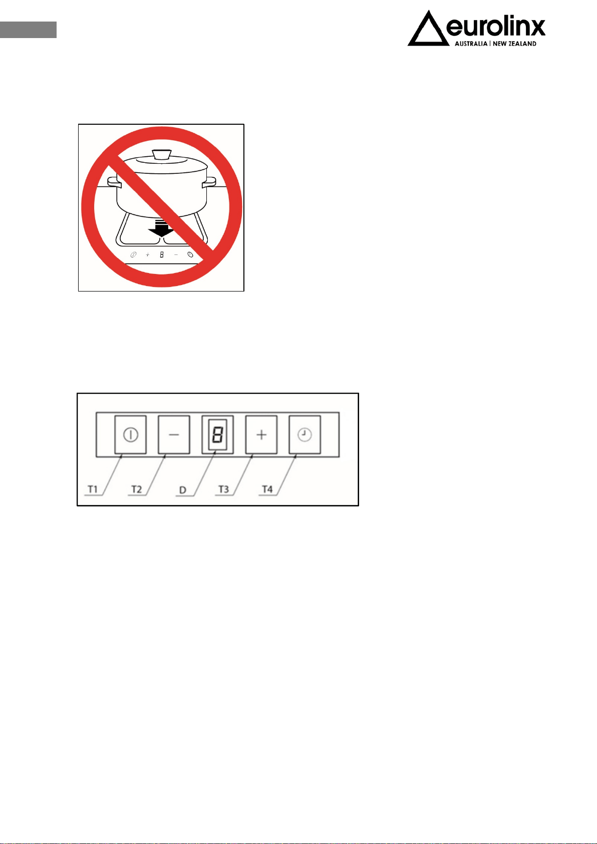
• Cooking zones may not be left in operation empty, without any dishes on top;
• Never use the glass surface as a working surface. Sharp objects may damage it;
• Preparation of food in aluminum or plastic cookware is not allowed. Never place any plastic objects
or aluminum foil upon the appliance surface;
• After using the appliance, disconnect it from the user’s interface. Do not trust the pot detector;
• Do not sprinkle or throw any water directly on the appliance;
• Do not flambé.
Fig. 2.3
7
EN
III INSTALLATION
III.1 PRELIMINARY INDICATIONS
Carefully read the guide before installation and use of the appliances.
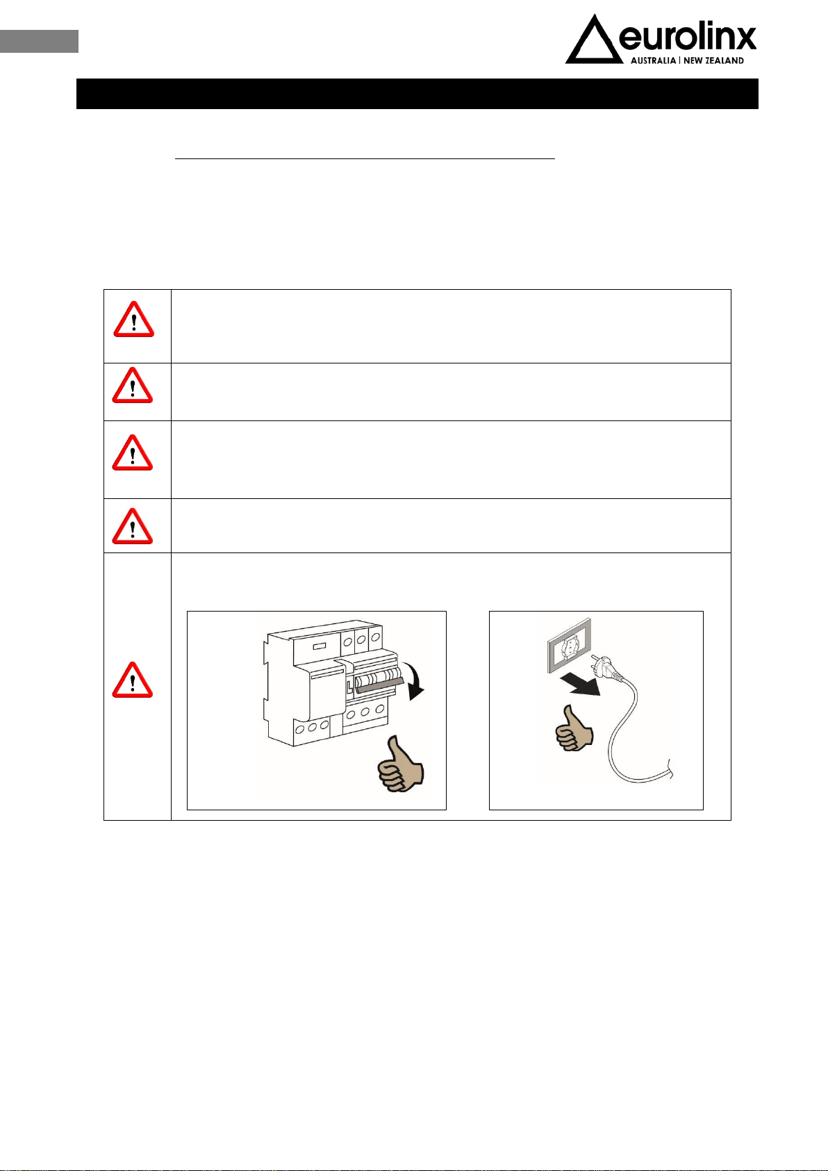
The installation requires safety equipment and a range of tool as per fig.3.1.
The aspiration hob is equipped with all the hardware needed for its installation and is
suitable for most furniture.
Important: eventually, more screws than necessary for installation have been provided so
it is normal to have some left at the end of the installation.
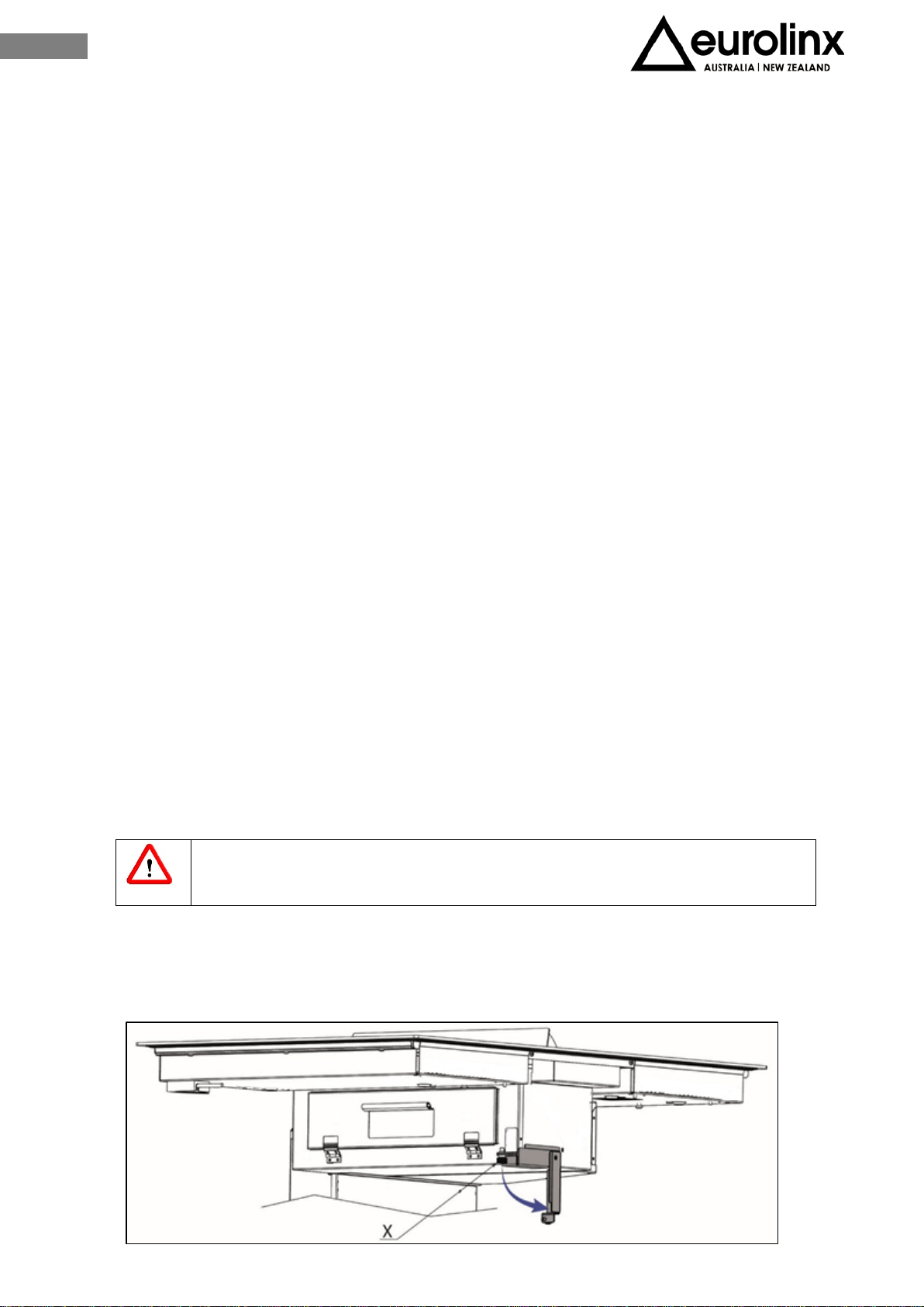
Check minimum dimensions of the base requested for installation (Fig. 3.2). Minimum
height of the kitchen plinth is very important (min. 100 mm) in order to allow the passage
of the air ducts below the base of the furniture. Upon request, it is possible to purchase
a special kit for kitchen plinth up to 60 mm height.
Fig. 3.1
Fig. 3.2
8
EN
The furniture finishing should be treated with heat resistant glue (100°C) otherwise its
shape and colour may change due to the inferior heat resistance.
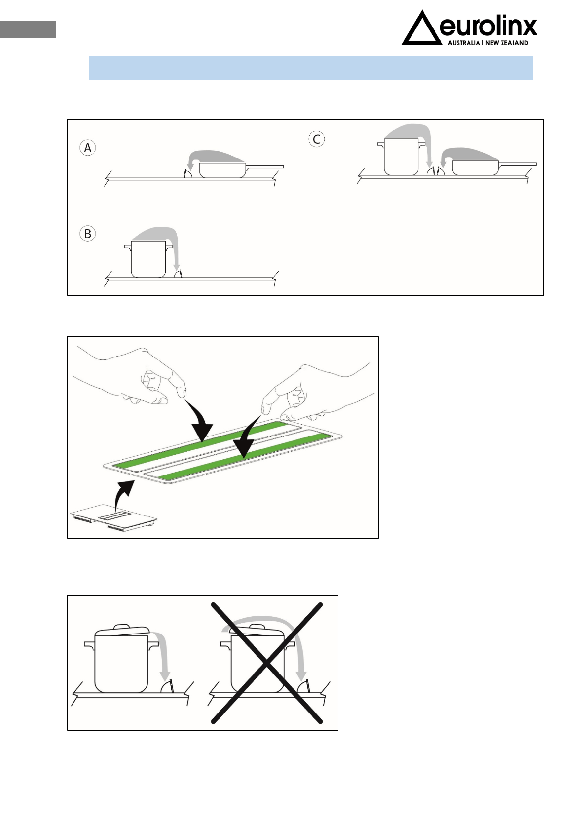
Ideally the appliance should be installed without any adjacent furniture or walls on both
sides (Fig.3.3-A). Furniture on only one side of the appliance is allowed (Fig.3.3-B
andFig.3.3-C). To prevent fire hazard it is strictly forbidden to install any furniture or
walls higher than the appliance on both sides (Fig.3.3-D).
Use of wood decoration plates or boards is not permitted
Minimum distance between the edge of the appliance and the furniture / wall is 250 mm
(Fig.3.4).
Fig. 3.3
Fig. 3.4
9
EN
On the front part there must be an opening of no less than 5 mm (Fig.3.5 dimension a).
It is recommended to install the appliance only after having installed the kitchen base
cabinet in order to avoid eventual damages to the glass hob.
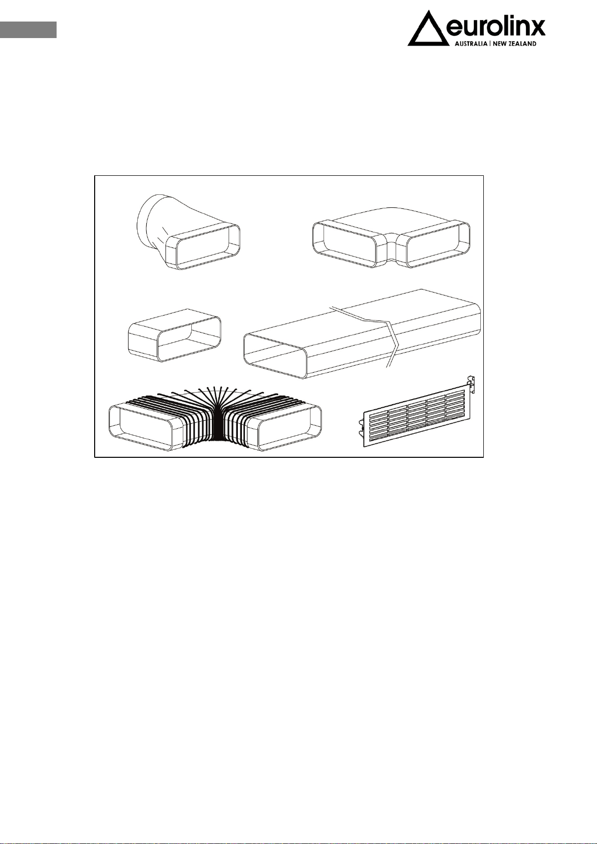
III.1.a AIR TREATMENT
Questo dispositivo consente il trattamento dei fumi di cottura. Il sistema può essere
utilizzato in modalità aspirante o filtrante (kit filtri a carbone attivo o kit con filtro al
plasma fornibile separatamente).
Duct-out. The kitchen fumes are expelled outside through the pipe (not supplied
with the hood) connected to the engine exhaust fitting
Warning! The piping must never be connected to combustion
discharge pipes (stoves, boilers, burners, etc.)
The use of long pipes, with many bends, corrugated and with a diameter smaller than the
motor outlet’s will cause a decrease in extracting performance and a noise increase.
Filtering (recycling). The fumes pass through the active charcoal anti-odour
filter (not supplied with the hood) to be purifed and recycled in the kitchen.
Fig. 3.5
Fig. 3.5
10
EN
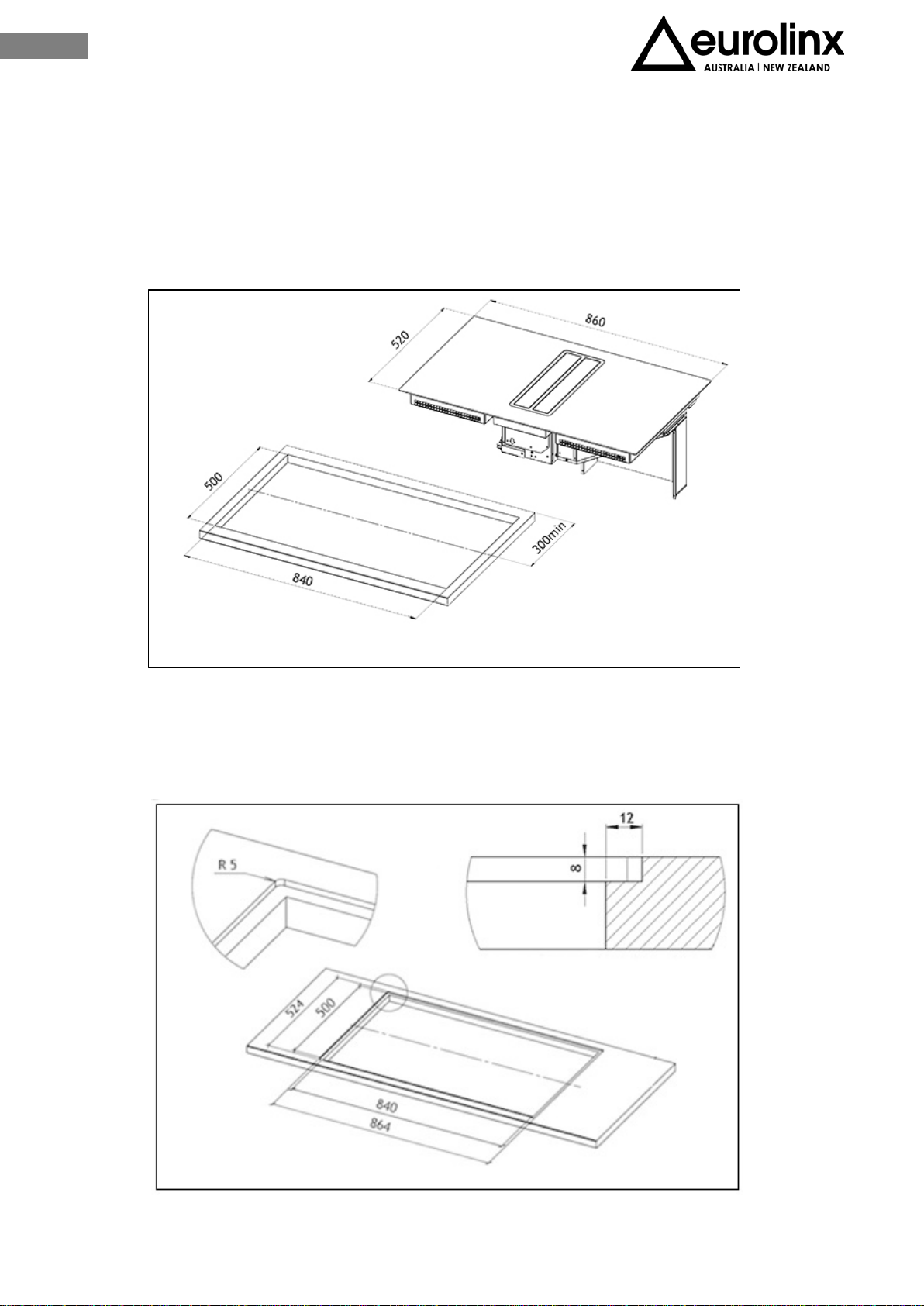
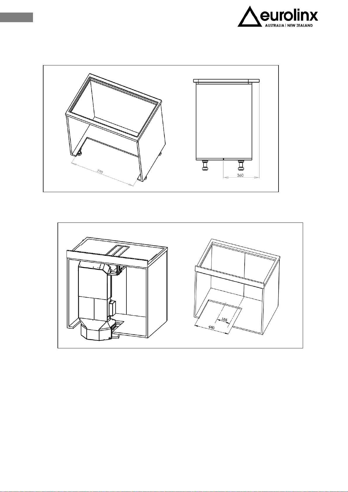
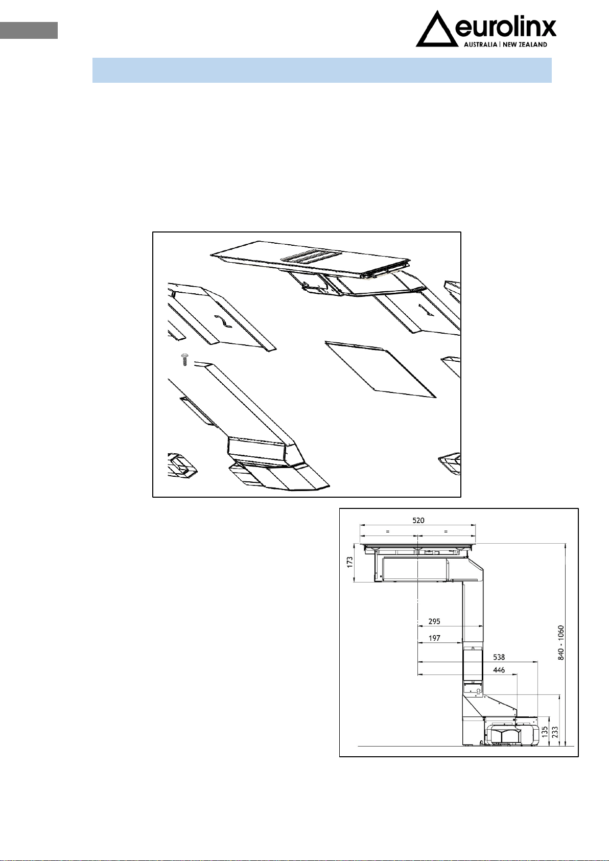
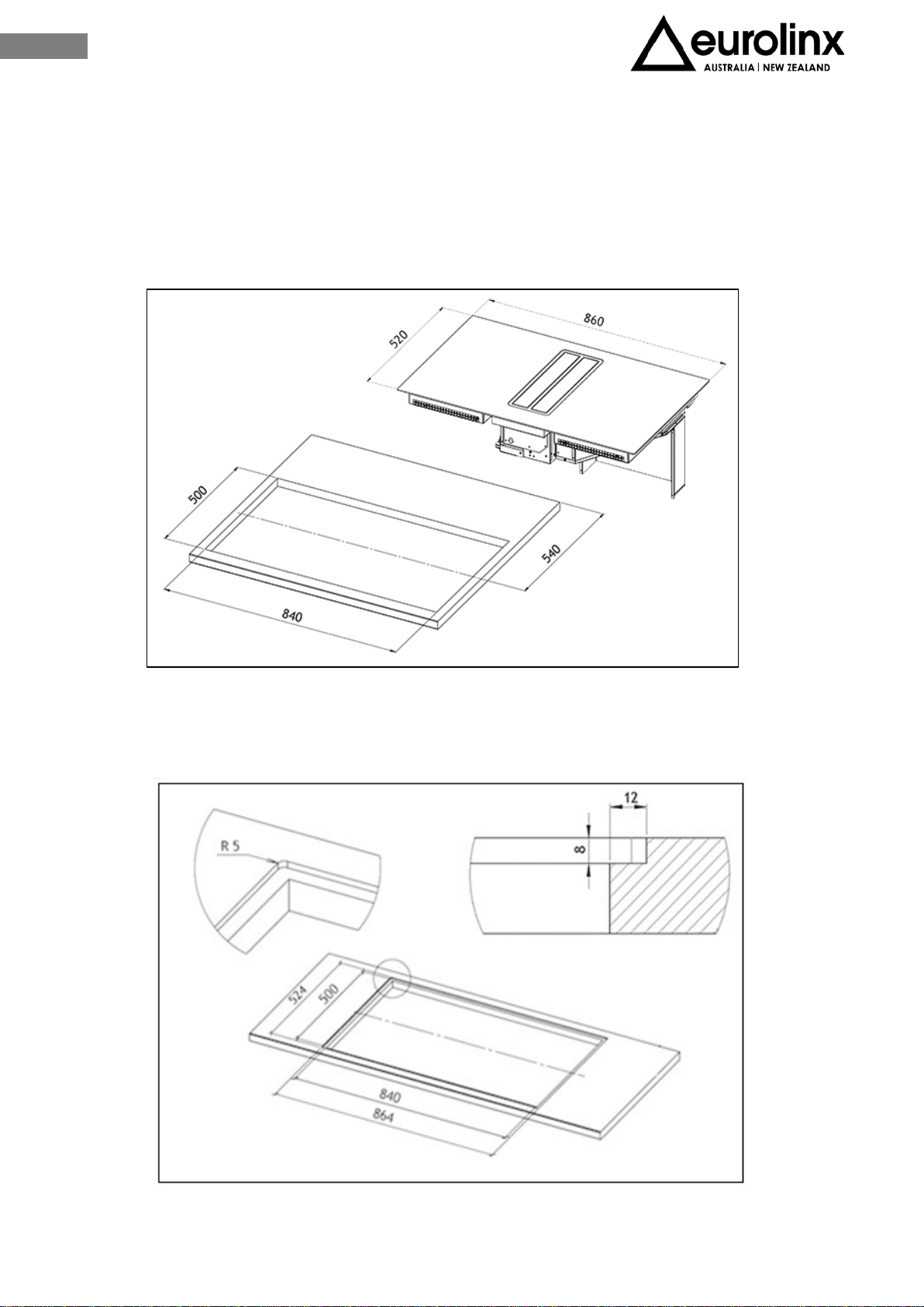
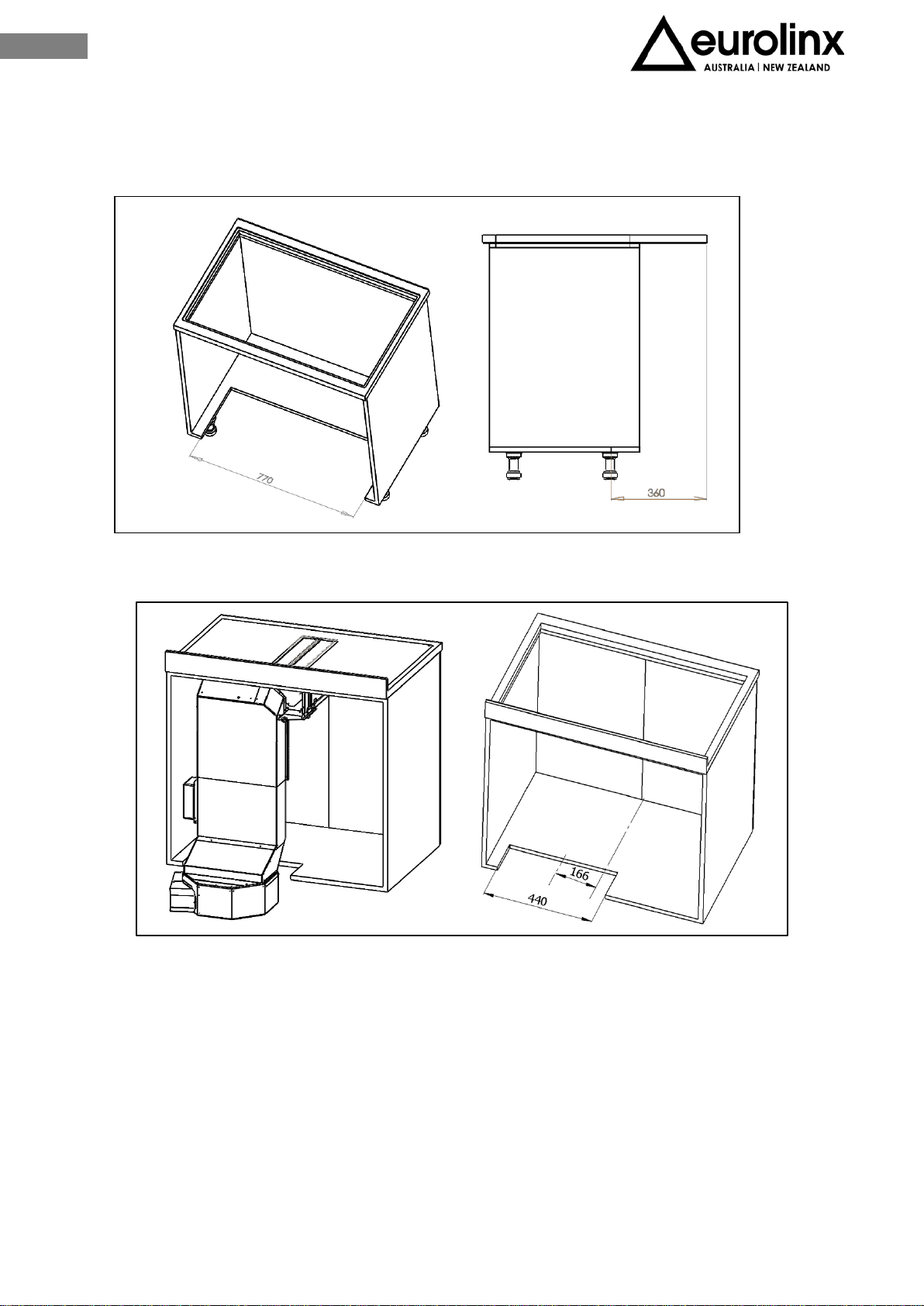
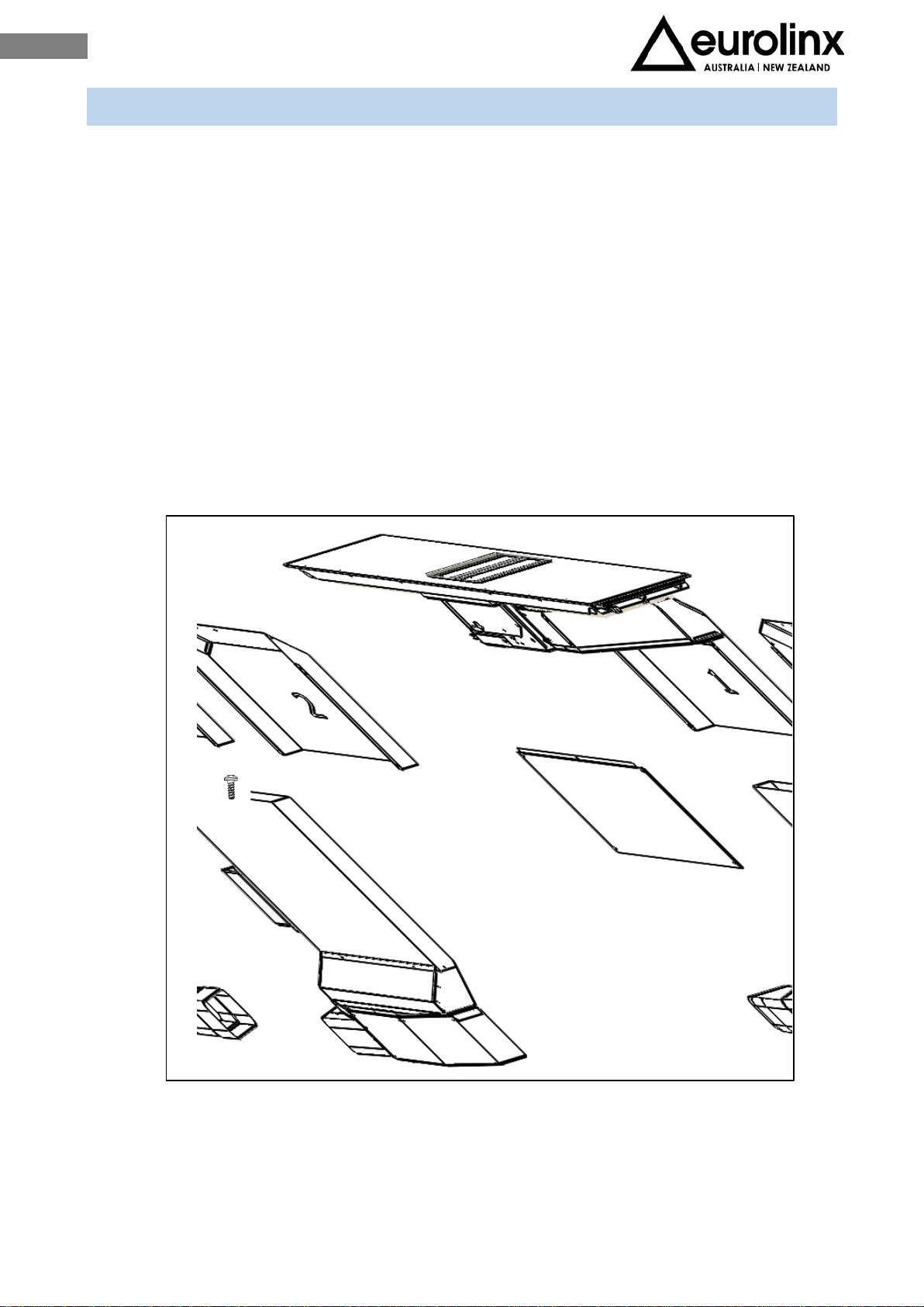
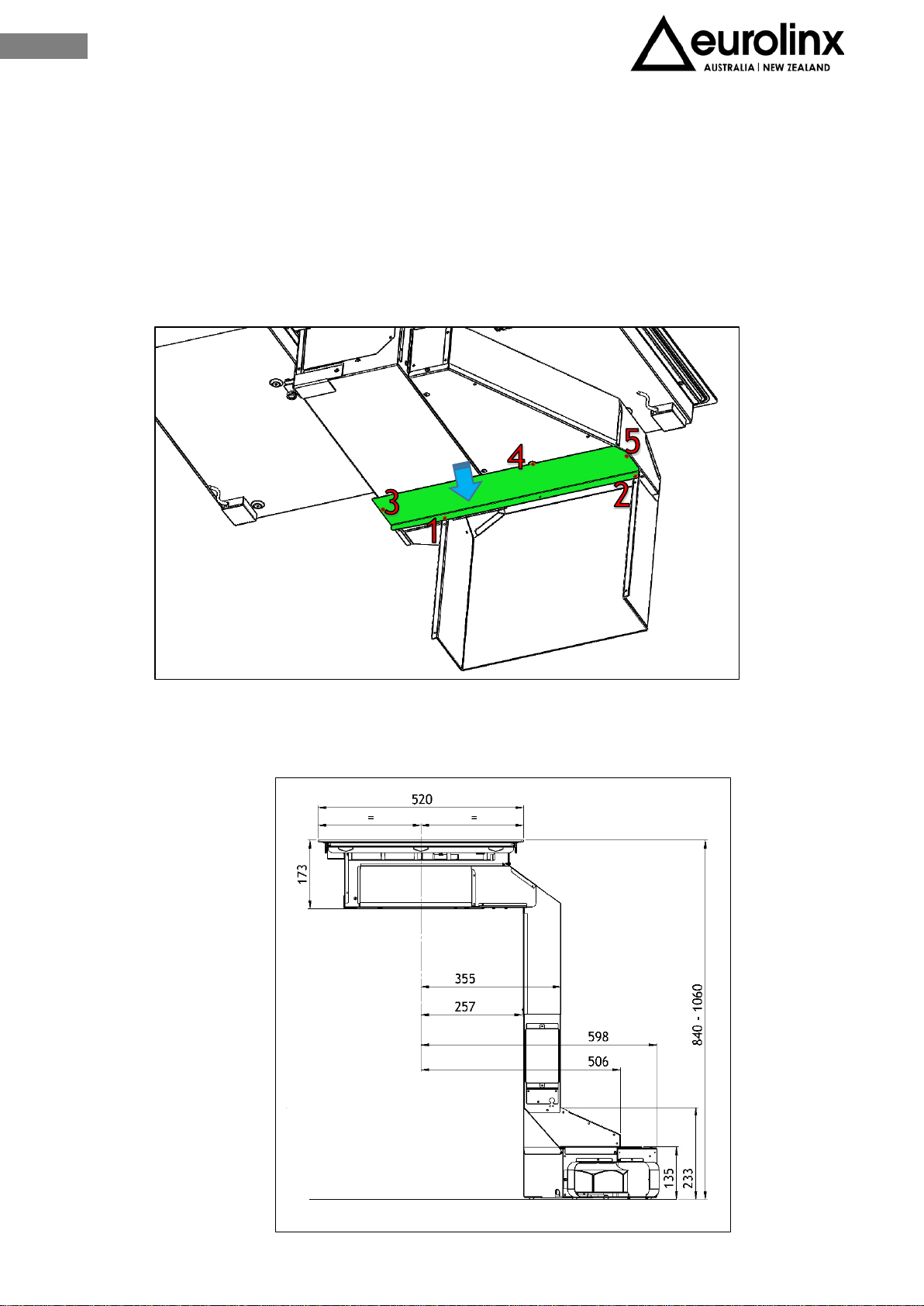
III.2 INSTALLATION ON UP TO 660 mm DEEP BASES
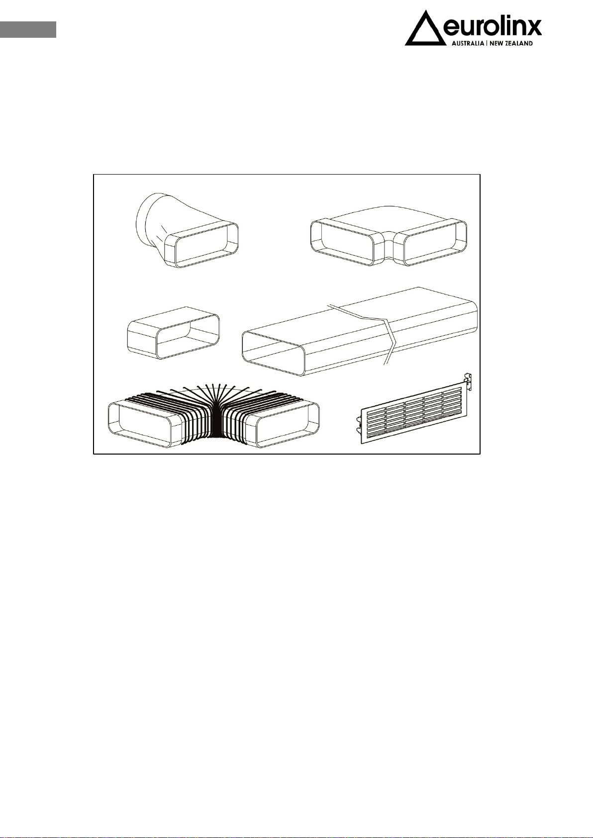
In the box the technician will find the elements shown on Fig. 3.6.
Elements must be mounted carefully following the procedure described in this guide.
The replacement fitting identified with "2" by a
marking on the back is not useful in this installation.
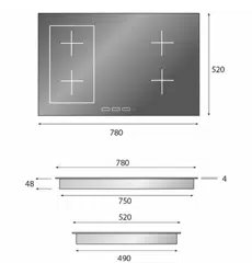
The device dimensions after installation are shown
at Fig. 3.7
The dimensions refer to the axis of the induction hob
and involve a specific configuration of the piece of
furniture, of the drawers that may be present and of
their own dimensions.
Fig. 3.7
11
EN
III.2.a INDUCTION HOB INSTALLATION
To leave the necessary space for the air pipes it is important to install the induction hob
with the centerline more than 300mm away from the wall on the back that may be
present.
Installation of the induction hob may be flush or non-flush.
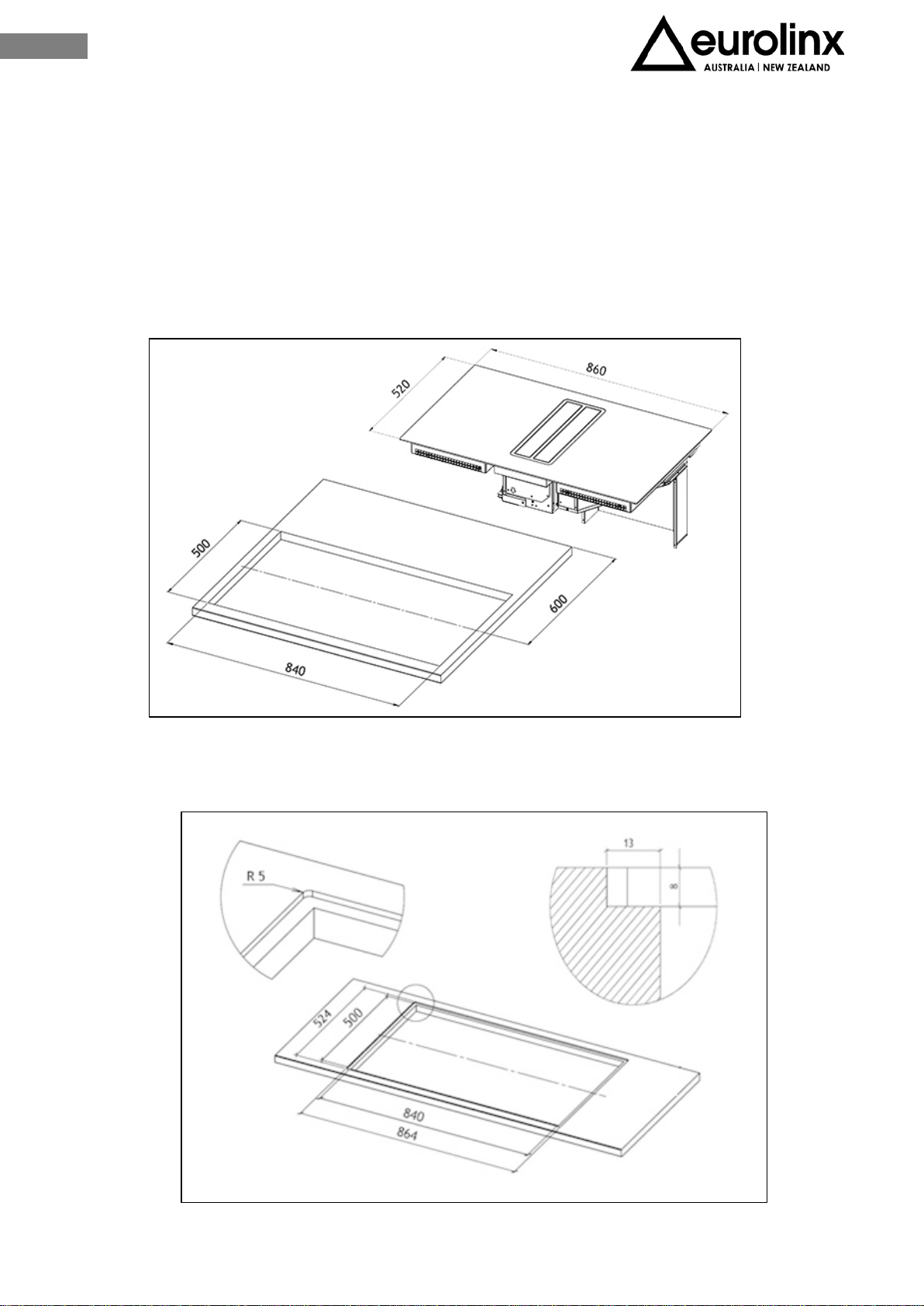
NON-FLUSH INSTALLATION: Prepare the hole in the worktop as shown on Fig. 3.8.
FLUSH INSTALLATION: Prepare the hole in the worktop, mill the worktop along the entire
edge of the hole. Be sure to comply with the dimensions indicated on Fig. 3.9.
Fig. 3.8
Fig. 3.9
12
EN
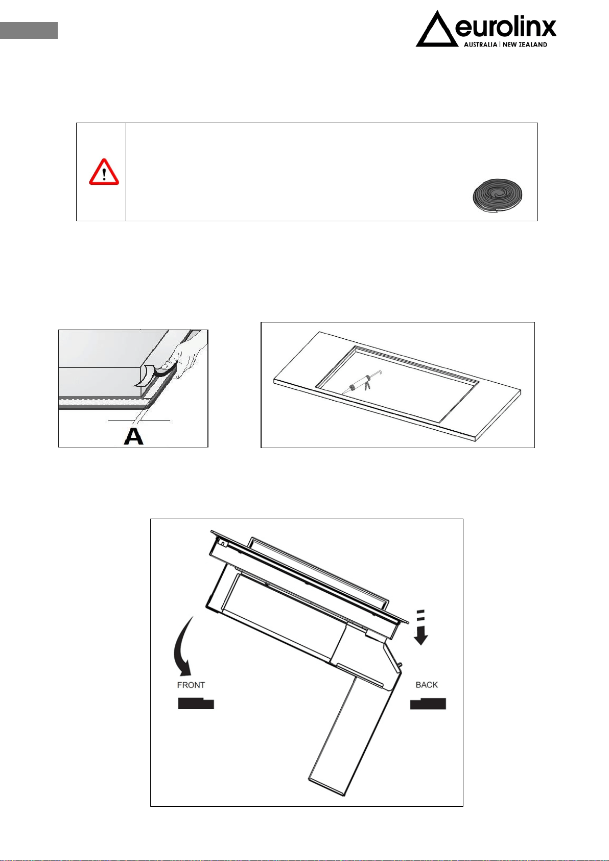
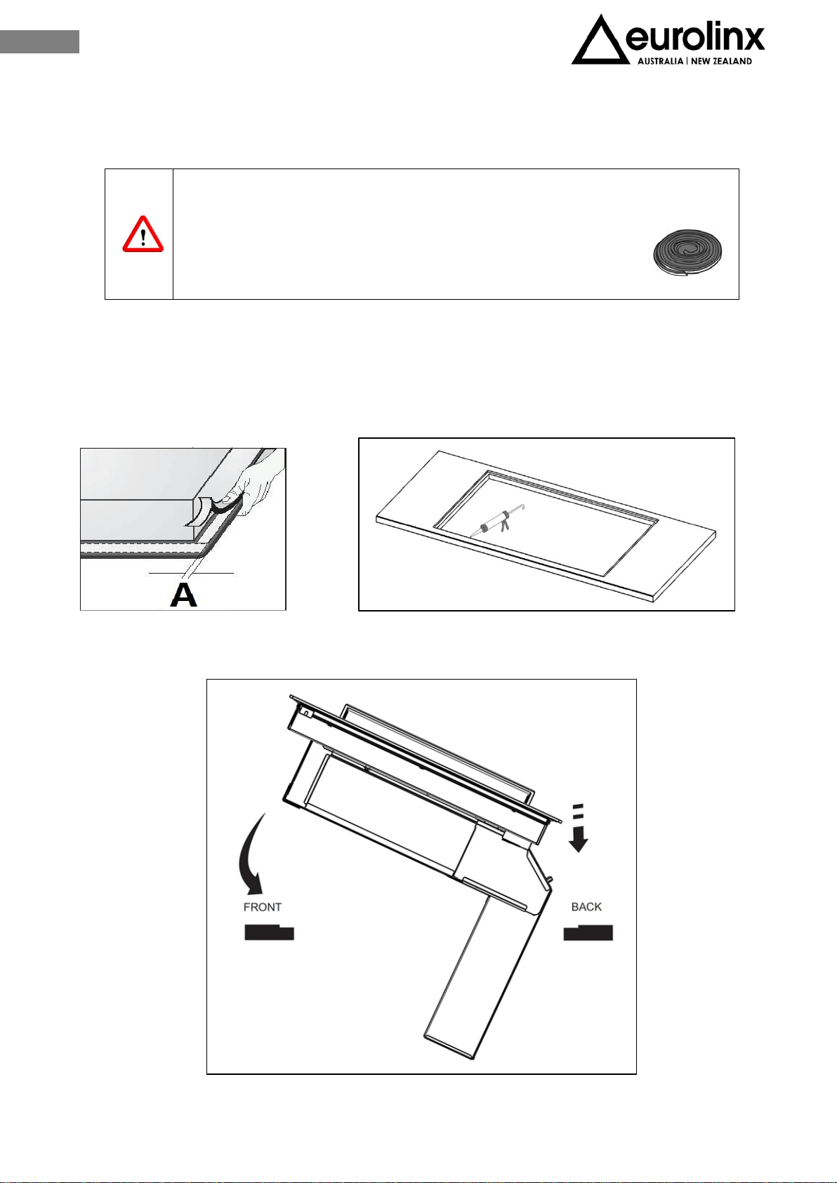
Before fixing the induction hob fix the foam gasket provided with the appliance on the
back of the hob.
CAUTION! It is forbidden to install the appliance without the foam gasket!
Remove the protective film and fix the foam gasket at a 2 mm distance from the edge of
the glass (A=2mm), The gasket must be attached along the entire length and should not
overlap at the corners (Fig.3.10).
Lay in the silicon sealant flush with the hole (Fig. 3.11), along the milling and lay the hob
on (Fig.3.12)
Fig. 3.10
Fig. 3.11
Fig. 3.12

13
EN
III.2.b EXECUTIVE DIRECTIONS
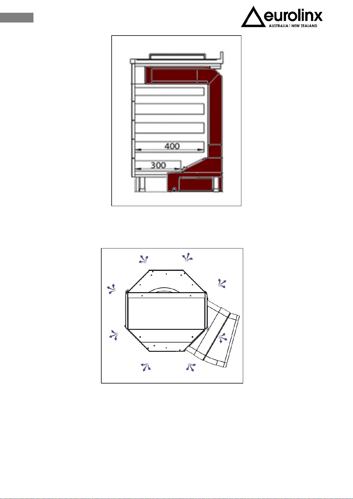
The base of the cabinet must be at least drilled as indicated in Fig. 3.13 and the back
removed in case.
If the installation does not include the optional plasma filtering kit the cut of the base
can be reduced as shown at Fig. 3.14
Installation of the appliance imply a maximum length of the drawers that may be mounted
under the hob (Fig. 3.15)
• Drawers depth = 400mm about
• Last drawer depth = 300mm
Fig. 3.13
Fig. 3.14
14
EN
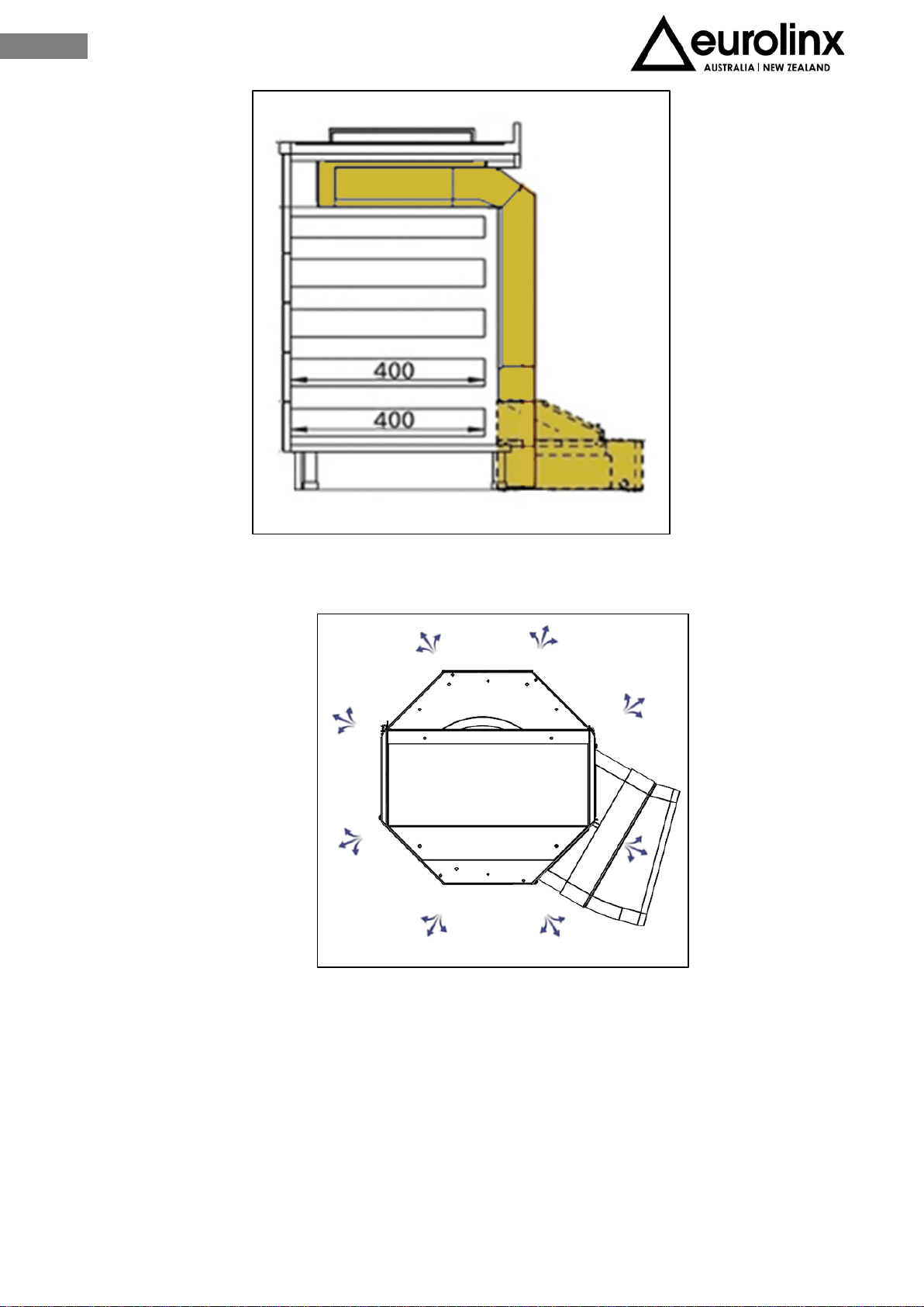
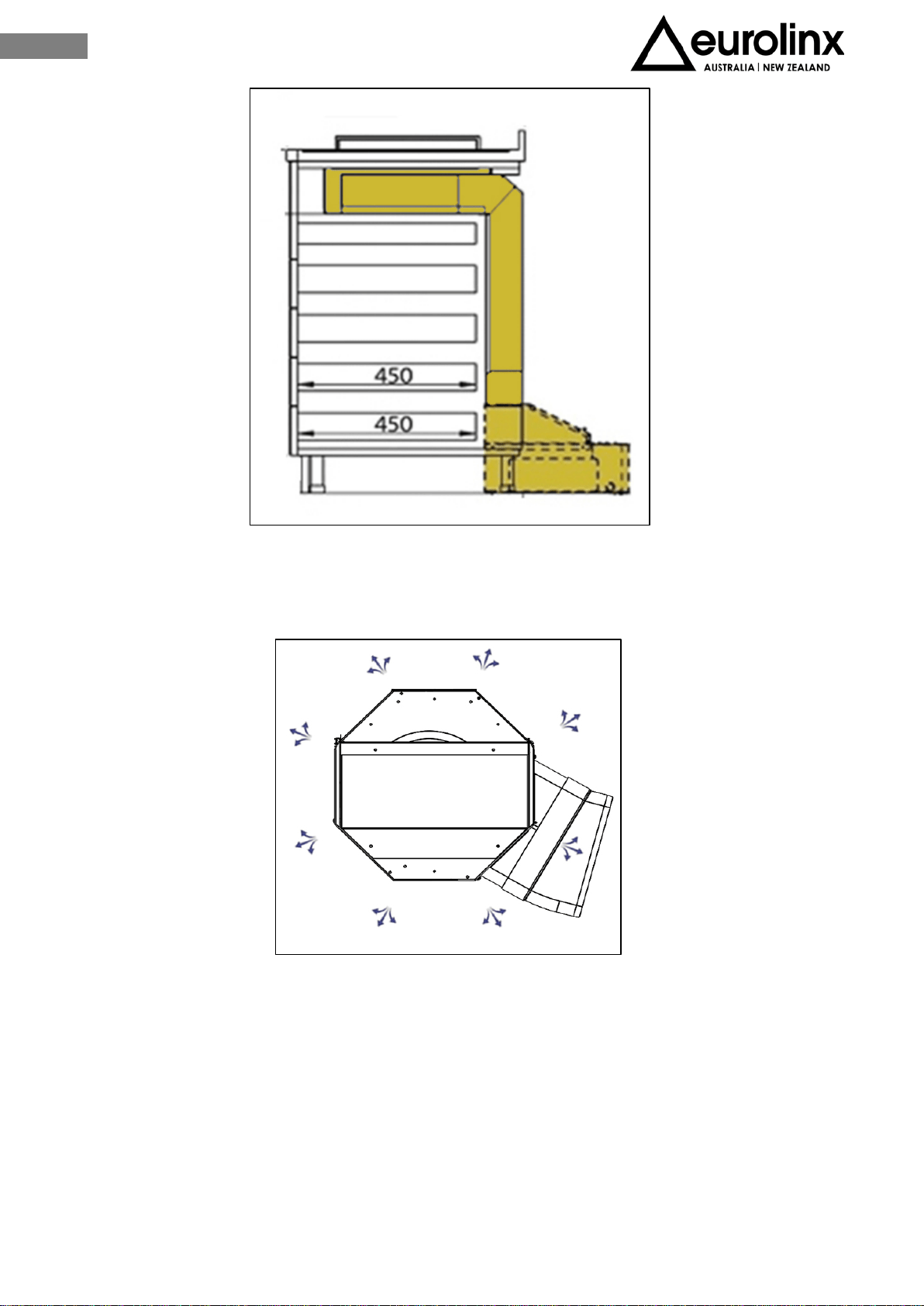
The next step is to determine the exit of the fumes according with the installation needs
(Fig. 3.16).
The air outlet can be rotated every 45 ° and thanks to the 15 ° fitting supplied with
the unit fitted in the two directions, it is possible to identify various configurations
for the outlet of the air duct.
To do this, you must cut the clamp that holds the power cable on the side of the
box, unscrew the screws that fix the octagonal box (Fig.3.17)
Fig. 3.15
Fig. 3.16
15
EN
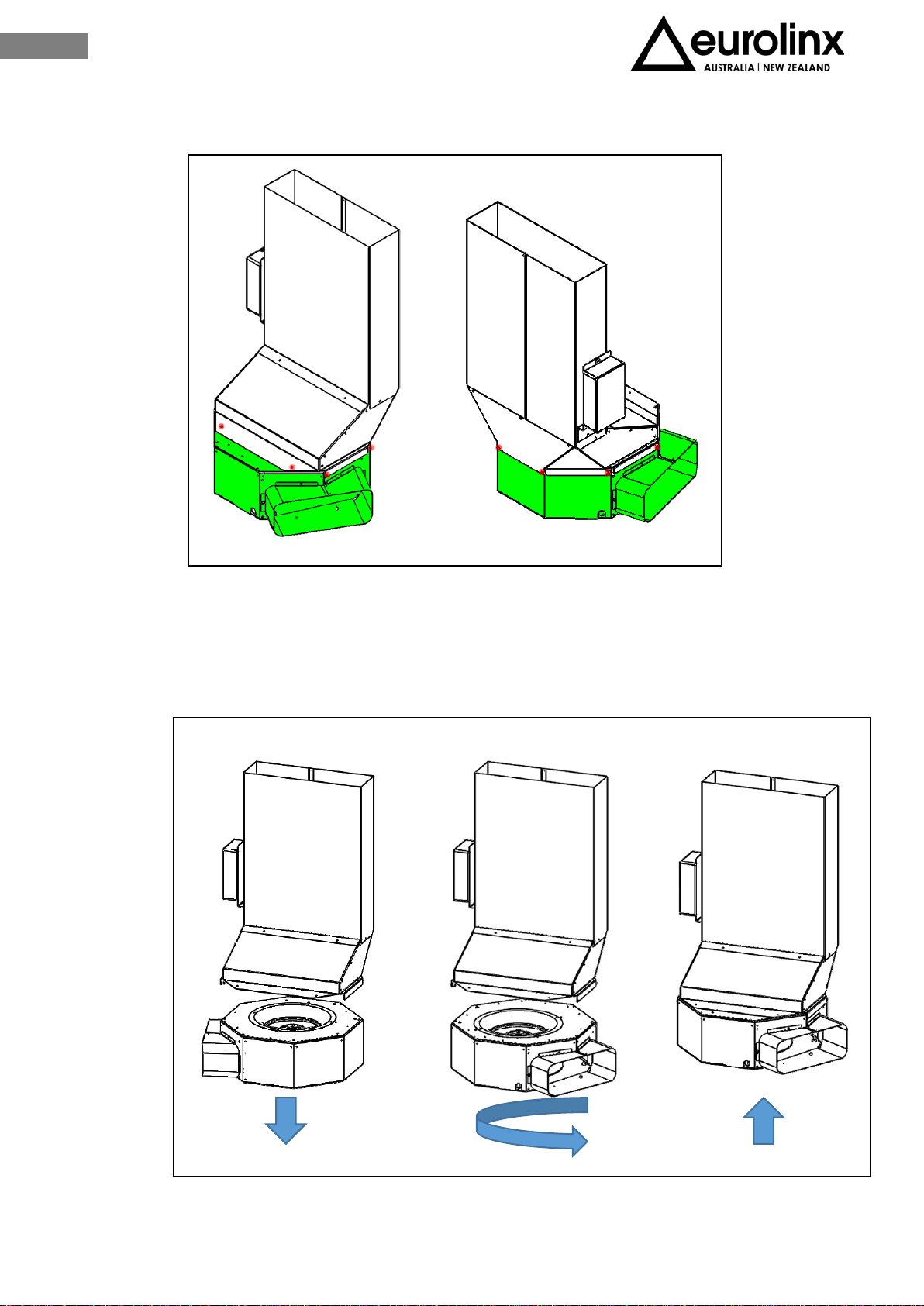
Turn the motor (Fig.3.18) and position it in the desired direction. Once the container box
is positioned, assemble it with the previously removed screws. The rear or front output is
possible by connecting a special curve, not supplied.
Fig. 3.17
Fig. 3.18
16
EN
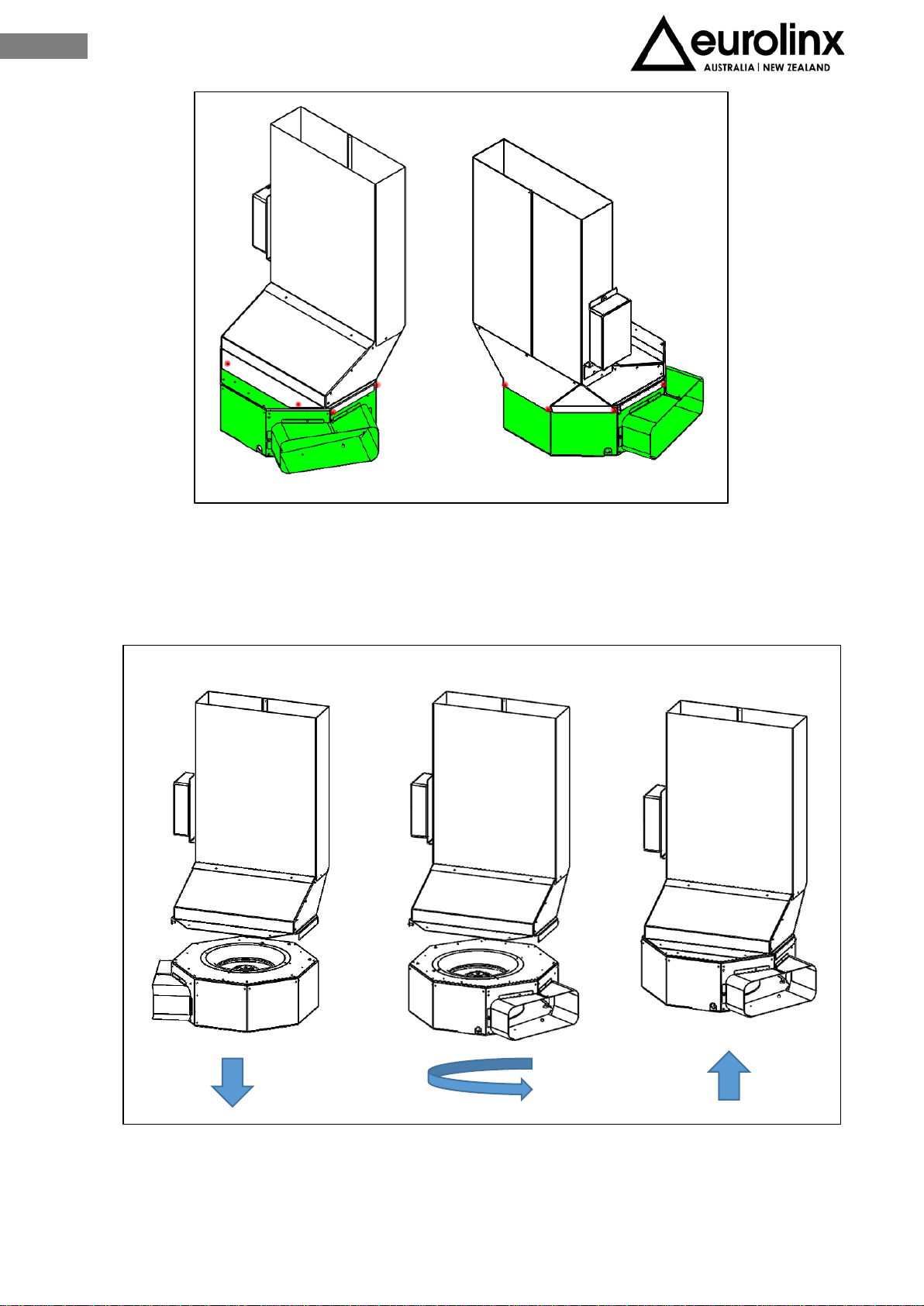
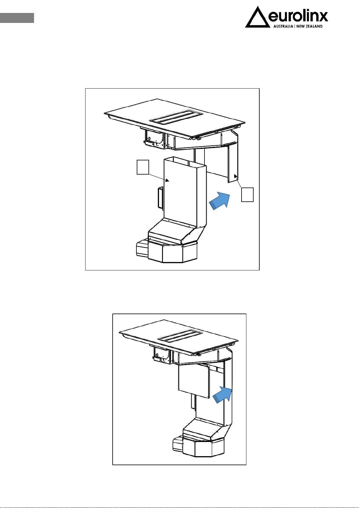
III.3.c ASPIRATION UNIT ASSEMBLY
After having determined the aspiration unit position, proceed by positioning it inside the
hole of the kitchen base previously cut (Fig. 3.13), making sure to recess the superior part
(Fig. 3.19-X) to the fix joint (Fig. 3.19-Y).
Proceed by fixing the cover to the vertical duct (Fig.3.20), using the special screws
included.
X
Y
Fig. 3.19
Fig.3.20
17
EN
It is now possible to joint up the external air exit for the fumes exhaust.
To place the exhaust pipe in the desired position it is necessary to buy spare joint pipes
not provided (Fig. 3.21).
All the pipes must pass under the base of the piece of furniture, inside the lift of the
kitchen plinth.
Fig. 3.21
18
EN
III.3 INSTALLATION ON UP TO 840mm DEEP BASES
For installation on bases deep up to 660 mm the only installation possible is described at
paragraph III.3.b.
For bases deep more than 660mm in addition to the previous configuration it is possible
to increase the space for the drawers by replacing joint flagged by “1” (label on the back)
with the one flagged by “2”.
Follow the installation procedure described hereunder.
The technician will find in the box the elements described at Fig. 3.6.
Fig. 3.6
19
EN
Remove the joint “1”
To carry this operation out it is necessary to remove the screws from the joint as
shown on Fig. 3.22 and 3.23
Fig. 3.22-a
Fig. 3.23
20
EN
It is now possible to assemble the joint “2” by fixing the 4 screws previously
removed. (Fig. 3.21 a-bn°1-3-4-5). Screws at Fig. 3.22 – 3.23 a-b n°2-6 must be
fixed after moving the inferior cover.
To move the inferior cover remove the 3 screws (Fig. 3.24 3-4-5). Move the cover
forward covering the empty space left by the new joint and fix the 3 screws at the
new position. Then fix the joint and the cover with the two remaining screws (Fig.
3.24 1-2)
Once the new joint is mounted the dimensions after complete installation will be the
ones shown at Fig. 3.25
Fig. 3.24
Fig. 3.25
21
EN
III.3.a INDUCTION HOB INSTALLATION
To leave the necessary space for the air pipe it is important to install the induction hob
with the center line at more than 360mm distance from a possible wall on the back.
Installation of the induction hob can be flush or non-flush.
For non-flush installation: drill the worktop as shown at Fig. 3.26
For flush installation: drill the worktop and mill it all along the edge of the hole, following
sizes indicated Fig. 3.9.
Fig. 3.26
Fig. 3.9
22
EN
Before fixing the induction hob, glue the foam gasket included on the inferior part of the
glass.
Caution! It is forbidden to install the hob without the foam gasket!
Remove the protective film and glue the gasket at 2mm distance from the glass edge
(A=2mm), the gasket must be attached along the entire length and should not overlap at
the corners (Fig.3.10).
Lay in the silicone sealant flush at the hole (Fig. 3.11), place the induction hob (Fig.3.12)
Fig. 3.10
Fig. 3.11
Fig. 3.12
23
EN
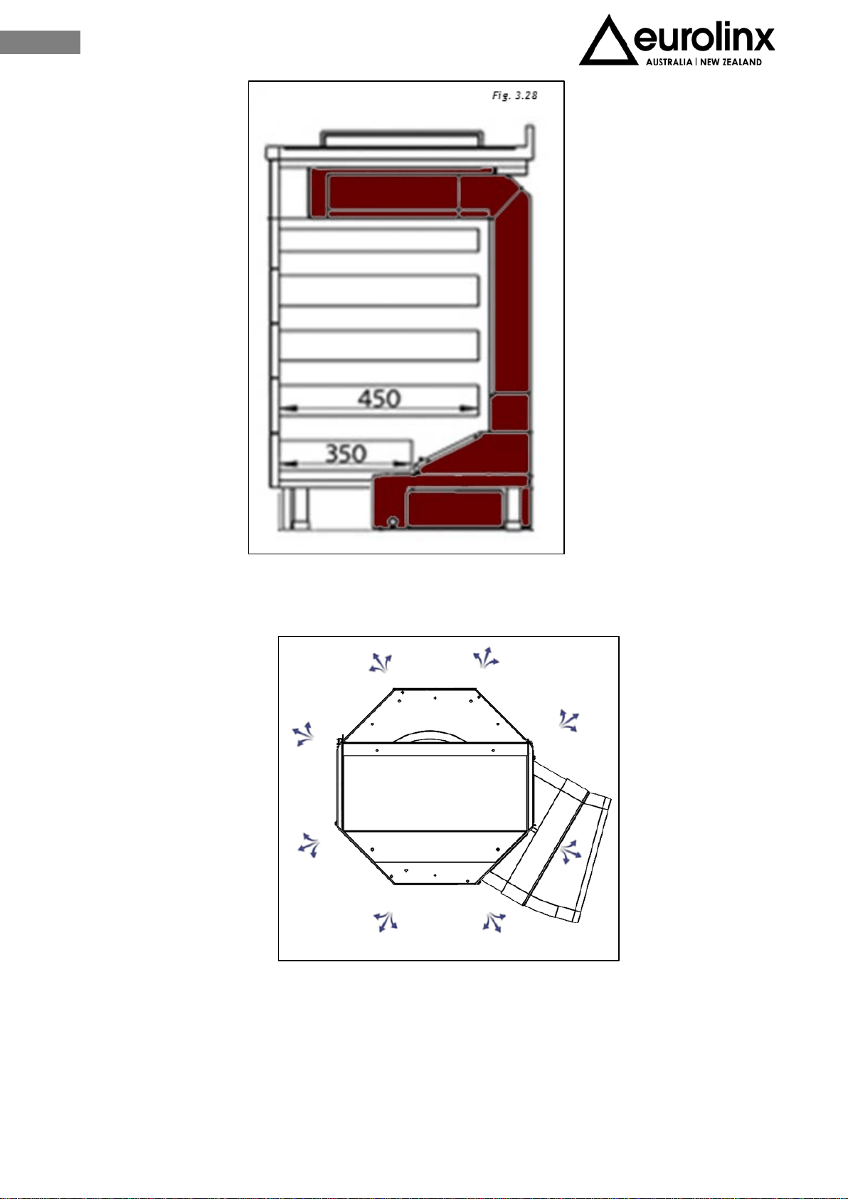
III.3.b EXECUTIVE DIRECTIONS
The base must be at least cut as shown in Fig. 3.27 and the back removed if needed.
If the installation includes the optional plasma filtering kit the cut on the base can be
reduced as shown at Fig. 3.14
The installation of the appliance imply a maximum length of the drawers that may be
mounted under the hob (Fig. 3.28).
• Drawers depth= 450mm about
• Last drawer depth = 350mm
Fig. 3.27
Fig. 3.14
24
EN
The next step is to determine the exit of the fumes according with the installation needs
(Fig. 3.16).
The air outlet can be rotated every 45 ° and thanks to the 15 ° fitting supplied with
the unit fitted in the two directions, it is possible to identify various configurations
for the outlet of the air duct.
Fig. 3.16
25
EN
To do this, the clamp that holds the power cable on the side of the box must be
cut, unscrew the screws that fix the octagonal box (Fig.17)
Turn the aspirator (Fig.18) and position it in the desired direction. Once the
container box is positioned, assemble it with the previously removed screws. The
rear or front output is possible by connecting a special curve, not supplied.
Fig. 3.17
Fig. 3.18
26
EN
III.3.c ASPIRATION UNIT ASSEMBLY
After having determined the aspiration box position, proceed by positioning it inside the
hole of the kitchen base previously cut (Fig. 16), making sure to recess the superior part
(Fig. 3.19-X) to the fix joint (Fig. 3.19-Y).
Proceed by fixing the cover to the vertical duct (Fig.3.20 ), use the special screws
included.
X
Y
Fig. 3.19
Fig.3.20

27
EN
It is now possible to joint up the external air exit for the fumes exhaust.
To place the exhaust pipe in the desired position it is necessary to buy spare joint pipes
not provided (Fig. 3.21).
All the pipes must pass under the base of the piece of furniture, inside the lift of the
kitchen plinth.
Fig.3.21
28
EN
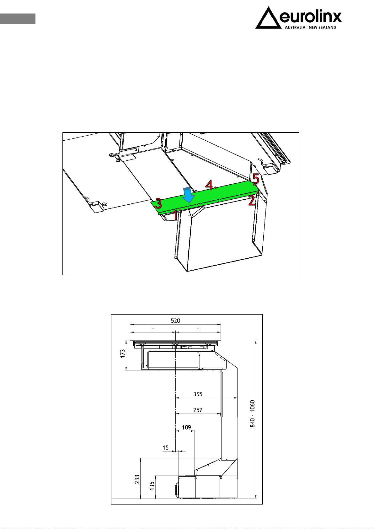
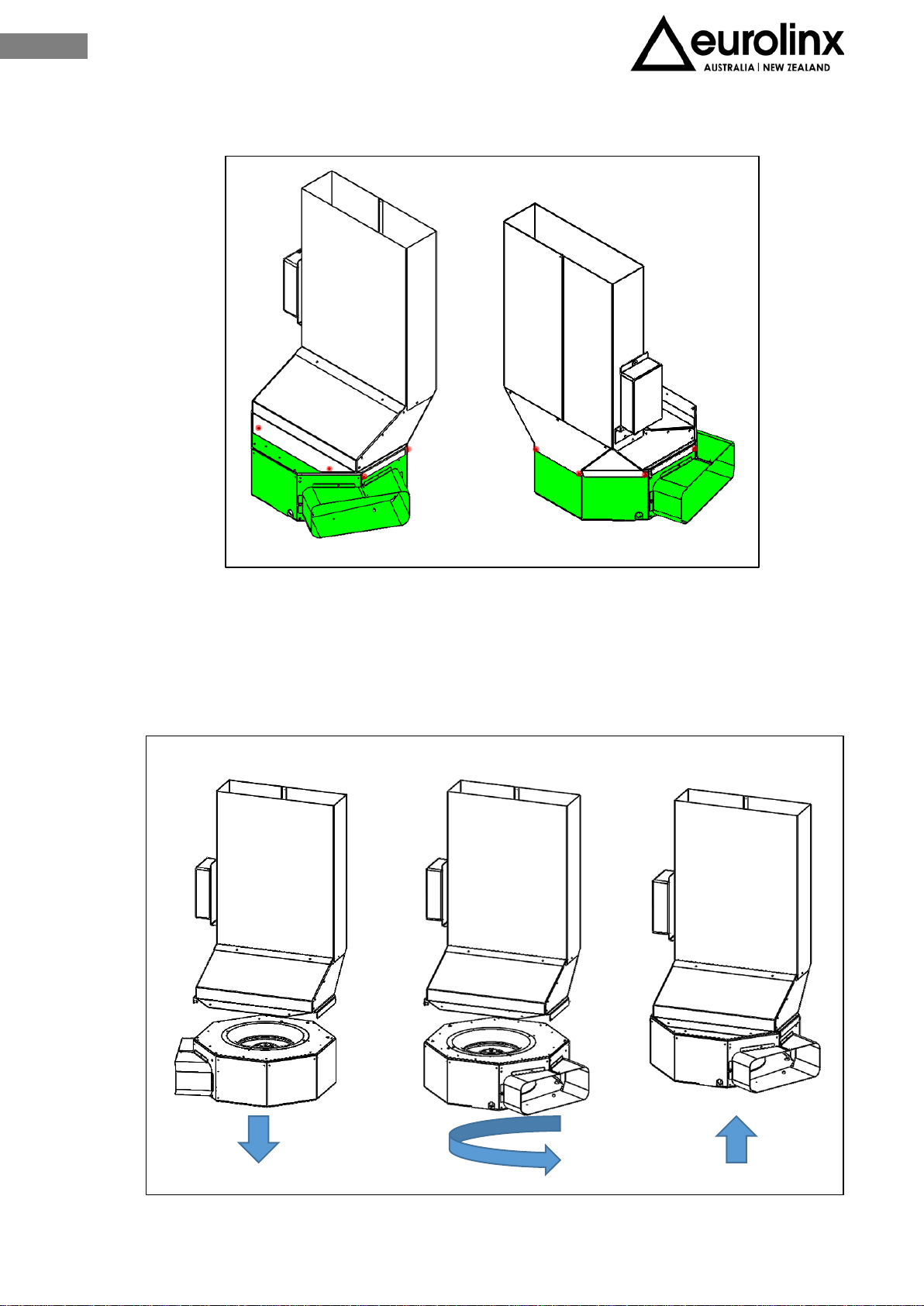
III.4 INSTALLATION ON UP TO 900mm DEEP BASES
For installation on bases deep up to 840mm the the only options are described at previous
paragraphs III.2, III.3.
With a kitchen top deeper than 840mm further to the previous options it is possible to
rotate the aspiration box in order to have more space available inside the furniture.
In the box the technician will find the elements shown on Fig. 3.6.
Elements must be mounted carefully following the procedure described in this guide.
The replacement fitting identified with "2" by a
marking on the back is not useful in this
installation.
The device dimensions after installation are
shown at Fig. 3.29
The dimensions refer to the axis of the induction
hob and involve a specific configuration of the
piece of furniture, of the drawers that may be
present and of their own dimensions.
Fig. 3.6
5
29
EN
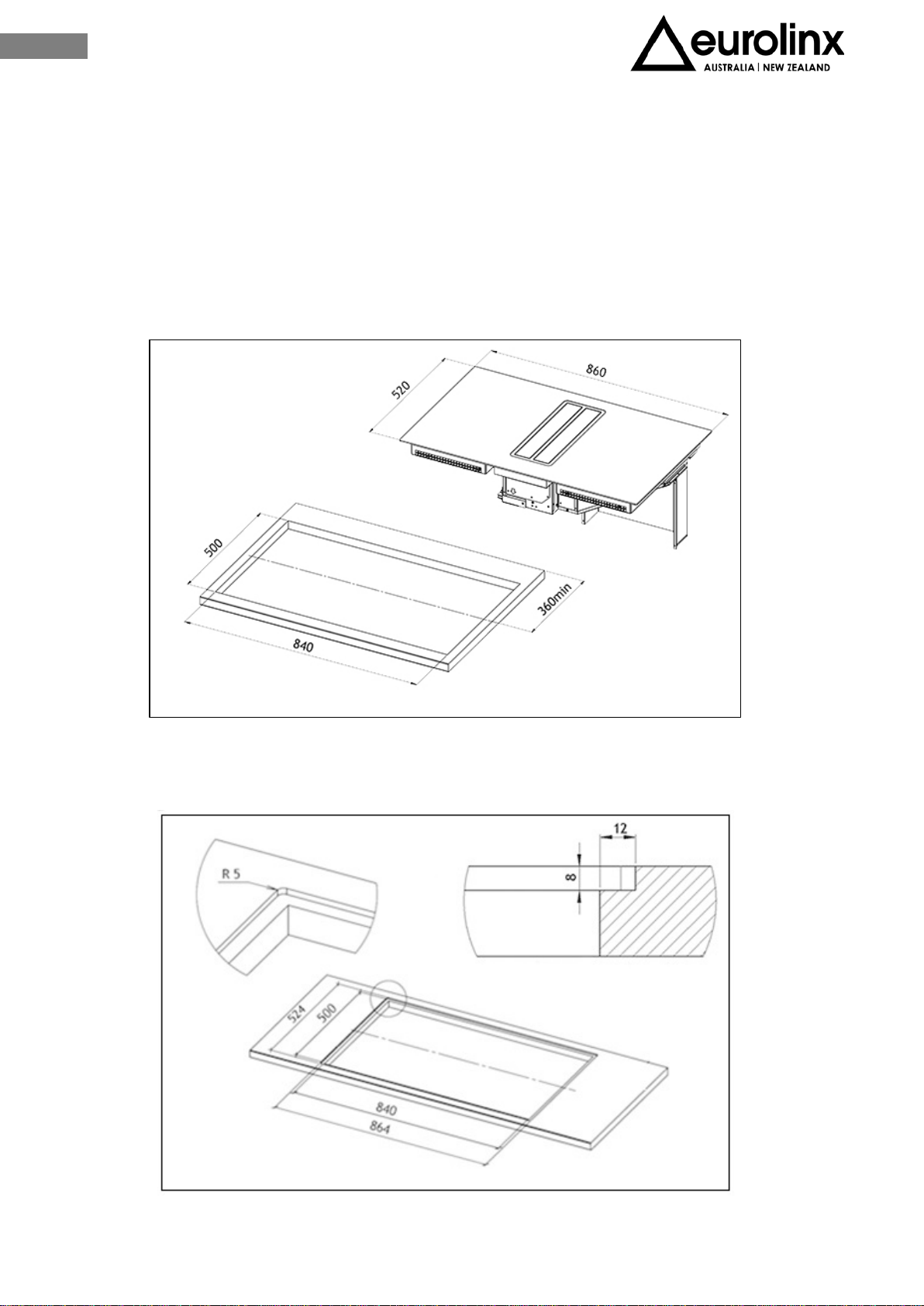
III.4.a INDUCTION HOB INSTALLATION
To leave the necessary space for the air pipes it is important to install the induction hob
with the centerline more than 540mm away from the wall on the back that may be
present.
Installation of the induction hob may be flush or non-flush.
NON-FLUSH INSTALLATION: Prepare the hole in the worktop as shown on Fig. 3.30.
FLUSH INSTALLATION: Prepare the hole in the worktop, mill the worktop along the entire
edge of the hole. Be sure to comply with the dimensions indicated on Fig. 3.9.
Fig. 3.30
Fig. 3.9
30
EN
Before fixing the induction hob fix the foam gasket provided with the appliance on the
back of the hob.
CAUTION! It is forbidden to install the appliance without the foam gasket
Remove the protective film and fix the foam gasket at a 2 mm distance from the edge of
the glass (A=2mm), The gasket must be attached along the entire length and should not
overlap at the corners (Fig.3.10).
Lay in the silicon sealant flush with the hole (Fig. 3.11), along the milling and lay the hob
on (Fig.3.12)
Fig. 3.10
Fig. 3.11
Fig. 3.12
31
EN
III.4.b EXECUTIVE DIRECTIONS
The base of the cabinet must be at least drilled as indicated in Fig. 3.30 and the back
removed in case.
If the installation includes the optional plasma filtering kit the cut on the base can be
reduced as shown at Fig. 3.32
Installation of the appliance imply a maximum length of the drawers that may be mounted
under the hob: (Fig.3.33)
• Drawers depth = 400mm about
Fig. 3.30
Fig. 3.31
Fig. 3.32
32
EN
The next step is to determine the exit of the fumes according with the installation needs
(Fig. 3.16).
The air outlet can be rotated every 45 ° and thanks to the 15 ° fitting supplied with
the unit installed in the two directions, it is possible to identify various
configurations for the outlet of the air duct.
Fig. 3.16
33
EN
To carry out this operation, the clamp that holds the power cable on the side of
the box must be cut and unscrew the screws that fix the octagonal box (Fig.17)
Turn the motor (Fig.3.18) and position it in the desired direction. Once the container box
is positioned, assemble it with the previously removed screws. The rear or front output is
possible by connecting a special curve, not supplied.
Fig. 3.17
Fig. 3.18

34
EN
III.4.c ASPIRATION UNIT ASSEMBLY
After having determined the aspiration box position, proceed by positioning it inside the
hole of the kitchen base previously cut (Fig. 3.33), making sure to recess the superior part
(Fig. 3.34-X) to the fix joint (Fig. 3.34-Y).
Proceed by fixing the cover to the vertical duct (Fig.3.35 ), use the special screws
included.
Fig. 3.34
Fig.3.34
Fig.3.35

35
EN
It is now possible to joint up the external air exit for the fumes exhaust.
To place the exhaust pipe in the desired position it is necessary to buy spare joint pipes
not provided (Fig. 3.19).
All the pipes must pass under the base of the piece of furniture, inside the lift of the
kitchen plinth.
Fig. 3.19
36
EN
III.5 INSTALLATION ON BASES DEEP MORE THAN 900mm
For installation on bases deep up to 900mm the only options are described at previous
paragraphs III.2, III.3, III.4.
With a kitchen top deeper than 900mm further to the previous options it is possible to
increase the depth available to the drawers thanks to the replacement of the connector
identified with "1" (marking on the back) with the one identified with "2".
To do this, the aspiration box must be rotated in order to make maximum space
available inside the piece of furniture.
Carefully follow the operations described below.
In the box the technician will find the elements shown on Fig. 3.6.
Elements must be mounted carefully following the procedure described in this guide.
Fig. 3.6
5x

37
EN
Remove joint “1”
To carry this operation out it is necessary to remove the screws from the joint as
shown on Fig. 3.22-a and 3.22-b
Fig. 3.22-a
Fig. 3.23-b
38
EN
It is now possible to assemble the joint “2” by fixing the 4 screws previously
removed (Fig. 3.21 a-bn°1-3-4-5). Screws at Fig. 3.21 a-b n°2-6 must be fixed after
moving the inferior cover.
To move the inferior cover remove the 3 screws (Fig. 3.22 3-4-5). Move the cover
forward covering the empty space left by the new joint and fix the 3 screws at the
new position. Then fix the joint and the cover with the two remaining screws (Fig.
3.22 1-2)
Once the new joint is mounted the dimensions after complete installation will be the
ones shown at Fig. 3.36
Fig. 3.24
Fig. 3.36
39
EN
III.5.a INDUCTION HOB INSTALLATION
To leave the necessary space for the air pipe it is important to install the induction hob
with the center line at more than 600mm distance from a possible wall on the back.
Installation of the induction hob can be flush or non-flush.
For non-flush installation: drill the worktop as shown at Fig. 3.37
For flush installation: drill the worktop and mill it all along the edge of the hole, following
sizes indicated Fig. .
Fig. 3.36
Fig. 3.9
40
EN
Before fixing the induction hob, glue the foam gasket included on the inferior part of the
glass.
Caution! It is forbidden to install the hob without the foam gasket!
Remove the protective film and glue the gasket at 2mm distance from the glass edge
(A=2mm), the gasket must be attached along the entire length and should not overlap at
the corners (Fig.3.10).
Lay in the silicone sealant flush at the hole (Fig. 3.11), place the induction hob (Fig.3.12)
Fig. 3.10
Fig. 3.11
Fig. 3.12

41
EN
III.5.b EXECUTIVE DIRECTIONS
The base must be at least cut as shown in Fig. 3.38 and the back removed if needed.
If the installation is including the optional plasma filtering kit the cut on the base can be
reduced as shown at Fig. 3.32
This installation of the appliance imply a maximum length of the drawers that may be
mounted under the hob (Fig. 3.39).
• Drawers depth = 450mm about
Fig. 3.38
Fig. 3.32
42
EN
The next step is to determine the exit of the fumes according with the installation needs
(Fig. 3.16).
The air outlet can be rotated every 45 ° and thanks to the 15 ° fitting supplied with
the unit installed in the two directions, it is possible to identify various
configurations for the outlet of the air duct.
Fig. 3.39
Fig. 3.16
43
EN
To do this, the clamp that holds the power cable on the side of the box must be
cut and unscrew the screws that fix the octagonal box (Fig.3.17)
Turn the motor (Fig.3.18) and position it in the desired direction. Once the container box
is positioned, assemble it with the previously removed screws. The rear or front output is
possible by connecting a special curve, not supplied.
Fig. 3.17
Fig. 3.18
44
EN
III.5.c ASPIRATION UNIT ASSEMBLY
After having determined the aspiration box position, proceed by positioning it inside the
hole of the kitchen base previously cut (Fig. 3.33), making sure to recess the superior part
(Fig. 3.33-X) to the fix joint (Fig. 3.33-Y).
Proceed by fixing the cover to the vertical duct (Fig.3.34 ), use the special screws
included.
Fig. 3.33
Fig. 3.35
45
EN
It is now possible to joint up the external air exit for the fumes exhaust.
To place the exhaust pipe in the desired position it is necessary to buy spare joint pipes
not provided (Fig. 3.19).
All the pipes must pass under the base of the piece of furniture, inside the lift of the
kitchen plinth.
Fig.3.19
46
EN
III.6 ELECTRICAL CONNECTION
The electrical connection must be carried out ONLY by qualified technicians.
The electrical protection of the electrical connection upstream of the equipment must
comply with the regulations in force.
Caution! Make sure that the voltage (V) and frequency (Hz)
indicated on the serial number plate located on the appliances
correspond to those available at the installation site.
Any change to the electrical installation necessary to install the hood should only be
undertaken by qualified staff.
After installation, insulated parts and those carrying electricity must be protected from
any possible contact.
Caution! If the electrical connection is carried out incorrectly or not
meeting the regulations, it may damage part of the appliance and the
warranty will not be valid.
Caution! Before any intervention, disconnect the appliance from the
power mains (fig.1-2 WARNING chapter).
These appliances must be earthed.
Two types of connections to the network are possible:
1. Using a standard plug connected (Fig. 3.55) to the power cord and inserted
into an accessible socket outlet (to be disconnected during service operations).
Make sure that the plug is accessible even after the complete installation of the
appliance.
Fig. 3.55
47
EN
Stable connection to the network by interposing a bipolar switch to ensure
disconnection from the network, with a contact opening distance allowing
complete disconnection under the conditions of the overvoltage category III, in
accordance with the installation rules (Fig. 3.56).
Earth connection (yellow-green wire) should not be interrupted.
If the power cord is damaged, it must be replaced by the manufacturer or its authorized
service center or by a qualified technician, in order to prevent any risk.
Connection procedure:
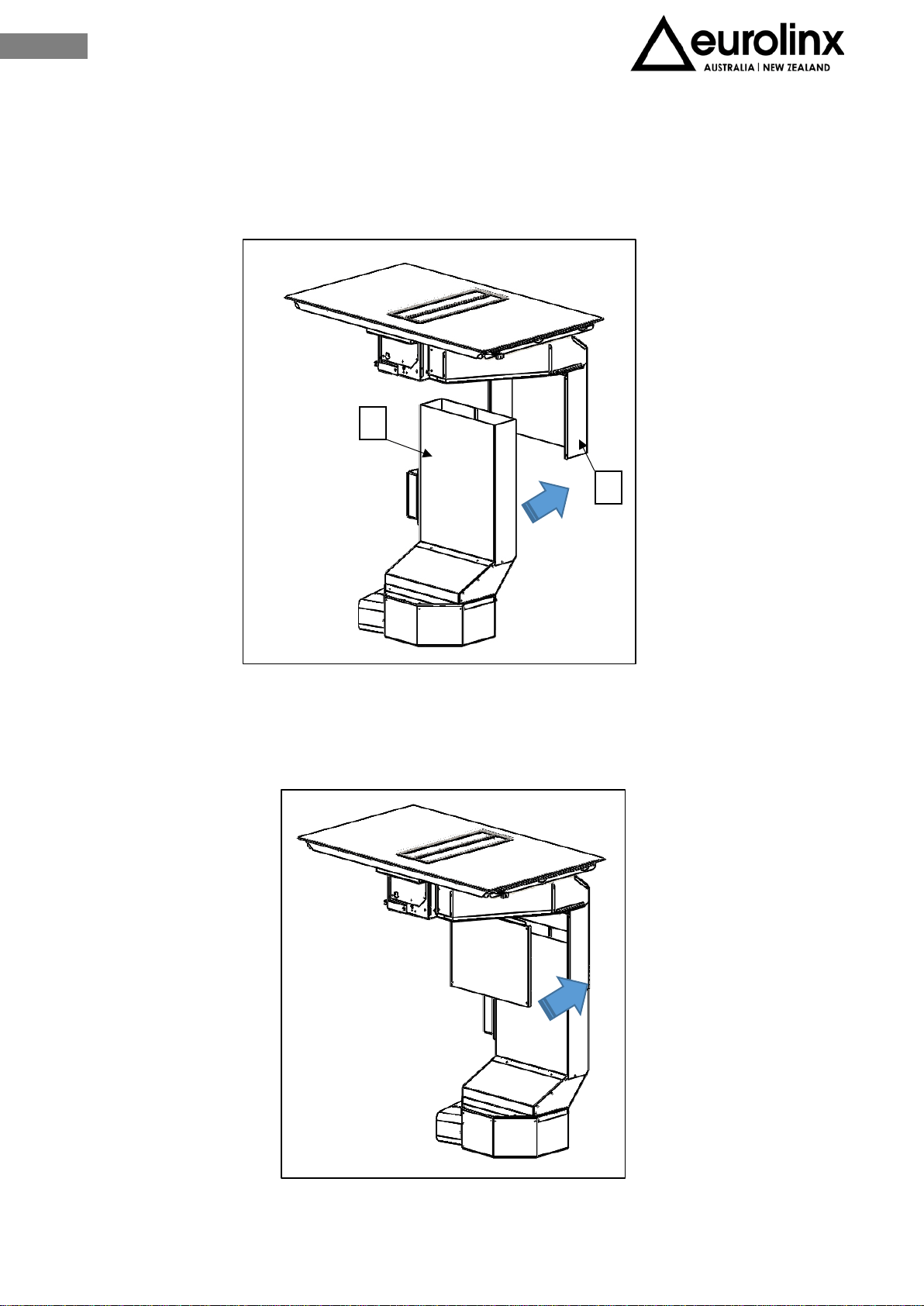
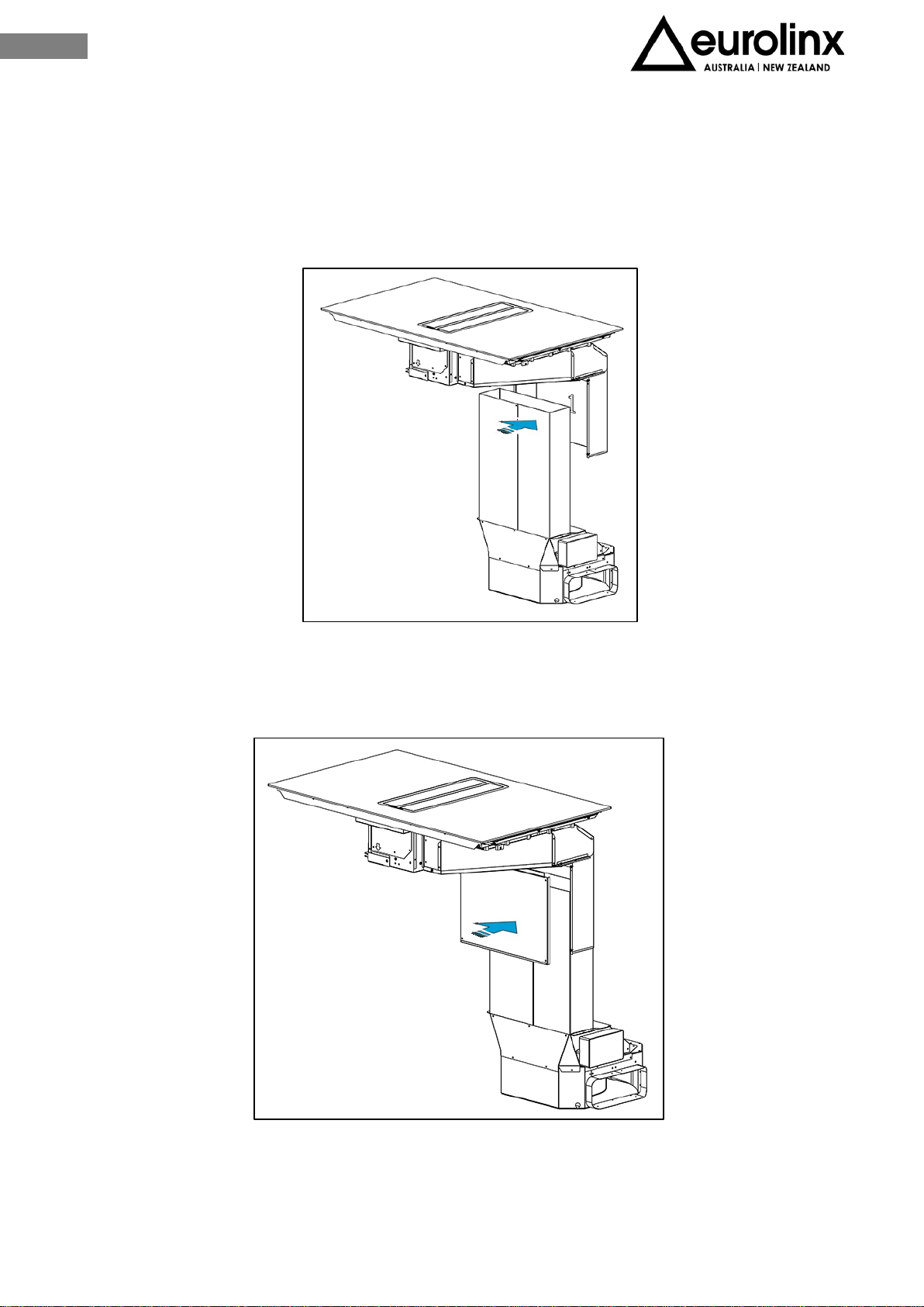
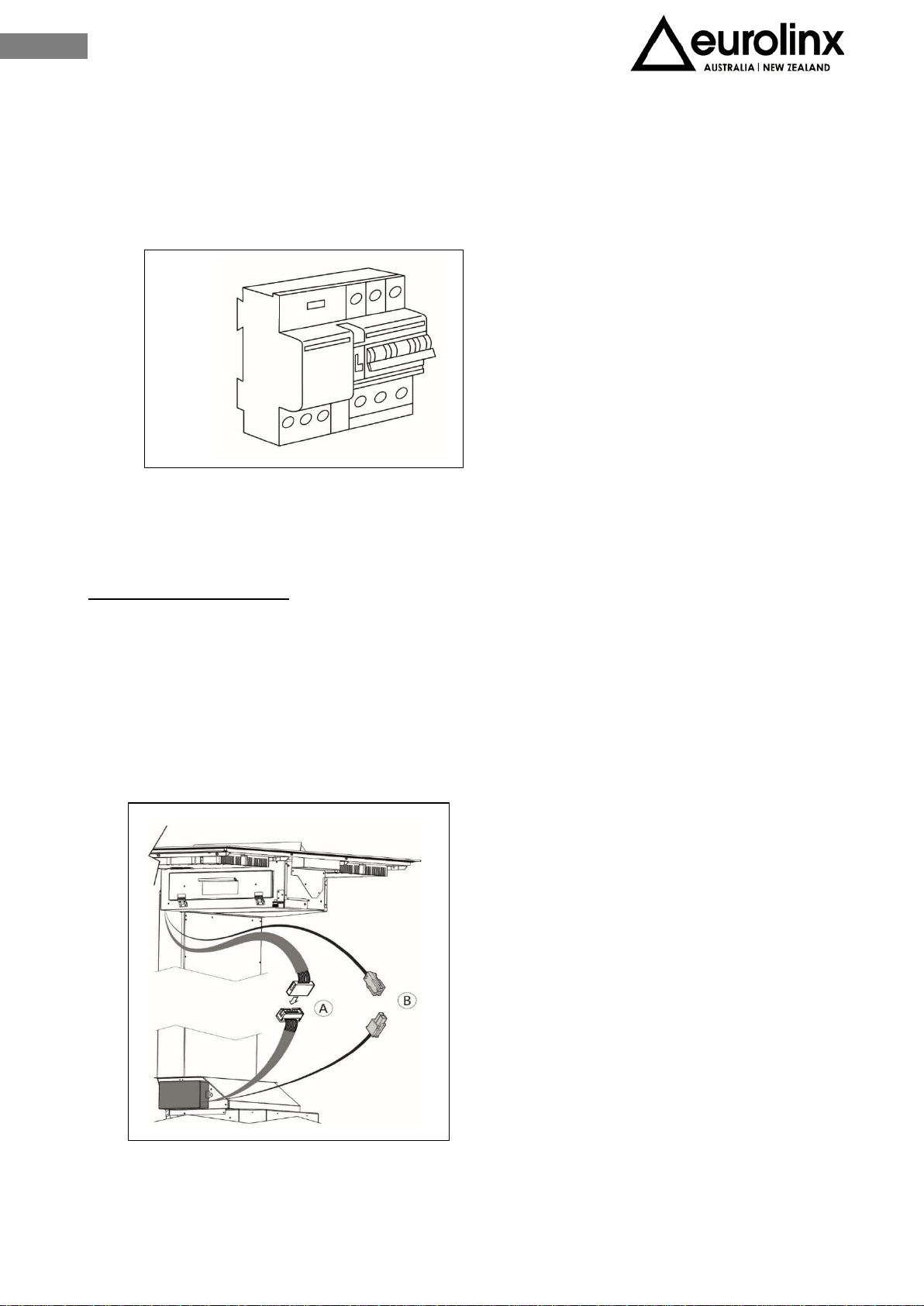
First of all connect the motor box to the induction hob:
• Connect the flat connector (male-female) to the main board, with the controls
falling down from the induction hob (Fig.3.57-A).
• Connect the main board connector (male-female) with the electronic water sensors
located inside of the hood (Fig.3.57-B).
Fig. 3.56
Fig. 3.57

48
EN
The appliance is composed by three devices that must be separately connected to the
electricity: the serial plates stating the electricity supply needed are located under each
side of the induction hob and on the upper aspiration unit.
Connection must be carried out by means of connection cables model H05V2V2-F,
following the instructions on the table below:
LINE
L
BROWN
EARTH
YELLOW/GREEN
NEUTRAL
N
BLUE
• After the connection switch the induction hob for about 3 minutes to make sure it
is operating correctly.
• Connection cable on the back sides of the appliance should NOT touch the appliance
back side, as this part will get very hot during operation.
Upon each connection to the power supply the sensors of the appliance are automatically
adjusted to ensure their proper function.
During this process all displays turn on and are lighted on for a few seconds.
During the adjustment procedure the sensors must be free of any objects, otherwise the
adjustment procedure will be interrupted.
During this process the use of the appliance is not possible.

49
EN
IV OPERATION
V.1 INDUCTION HOB TECHNICAL FEATURES
Supply Voltage
220-240Vac
Supply Frequency
50/60Hz
P
TOT
7400W
5
18x22cm / 2,1kW (P=3,7kW)
P = Maximum power
The wattage quoted may vary depending on the size and material of the pans used.
ENERGY EFFICIENCY
HOB TYPE
BUILT-IN
INDUCTION ZONES NR.
2
EC
PIANO ELETTRICO
190,7 Wh/Kg
ELECTRIC ZONE
EC
ZONA ELETTRICA
6
18x22cm
190,70h/kg
50
EN
V.2 APPROPRIATE POTS FOR INDUCTION
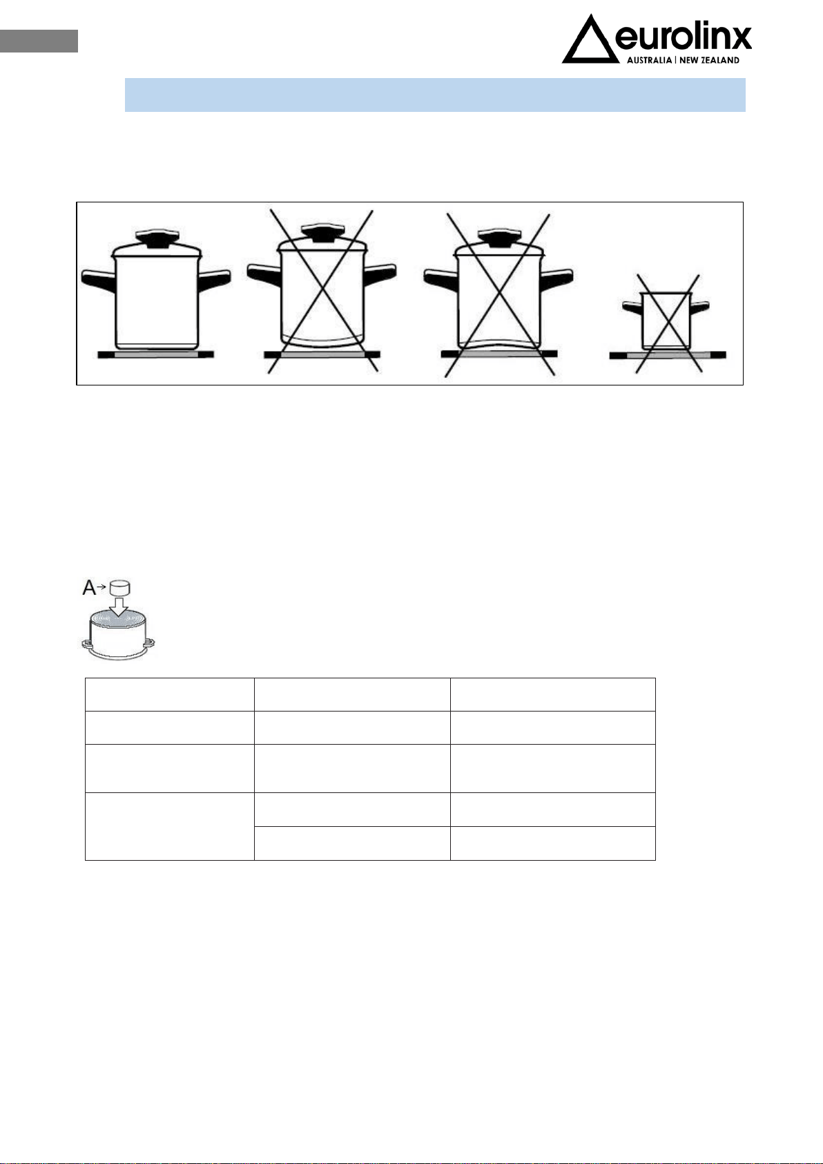
The induction works perfectly if you use the appropriate pots with the right pot sizes in
the inductor area (fig.29).
The pots during cooking must be at the center of the cooking zone. If the pressure cooker
is used, it should be kept under close supervision until it is pressurized. The induction
plane must first operate at maximum power, then follow the manufacturer's instructions.
When buying cookware, check the label “allows induction”.
Use small magnet (A) to test if the dish bottom is magnetic. Only dishes where
magnet sticks to the bottom are suitable.
ZONE
ØMIN. PAN BOTTOM
ØMAX. PAN BOTTOM
5 (single) Ø 12 cm Ø 18 cm
5 (single)
With bridge function
Ø 13,5 cm Ø 18 cm
5 (doouble)
With bridge function
Ø 20 cm Ø 23 cm
20 x 12 cm 39 x 23 cm
Note:
When Bridge function is selected, you can use the created zone in different ways, with
one or two pots.
If you use larger pots than the recommended maximum size, the heating time will be
longer, because the heating will propagate from centre to edges of the pot by conduction,
in this case also the temperature will be very uneven.
Fig. 29

51
EN
V.3 INDUCTION HOB OPERATION
POT DETECTOR
One of the advantages of induction appliances is the pot detector.
If there are no cookware on the cooking zone, the symbol will appear when the
appliance is switched on.
If, in 10 minutes time, a pan will be placed on the cooking zone, the zone will detect it
and it and will switch on to the set level.
When the pan is removed from the cooking area, the power supply stops. When placing
a pan with a diameter smaller than the cooking zone, the zone will use only the energy
needed to heat it.
THE APPLIANCE MAY BE DAMAGED IF:
- It is turned on and left empty, or an empty pot is placed on it;
- You don’t use the appropriate pots
- You use clay pots leaving scratches on the glass surface;
- Bottom of the pot is not perfectly dry;
- You use pots without a magnetic bottom.
Induction cooking zones are highly performing. The heat is formed directly into the bottom
of the pot, where it serves more, without unnecessary dispersion through the glass
surface.
The glass surface does not heat directly, but only with the heat coming back from the pot.
At the time the unit is switched on, all the displays / led (for a moment) will light up.
The unit is equipped with electronic sensors that light up if you touch the indicated
surfaces for at least 1 second.
Each sensor activation is followed by a sound signal.
Avoid placing any objects on sensor surface (possible error signal_ ).
Always keep the sensor surface clean.
52
EN
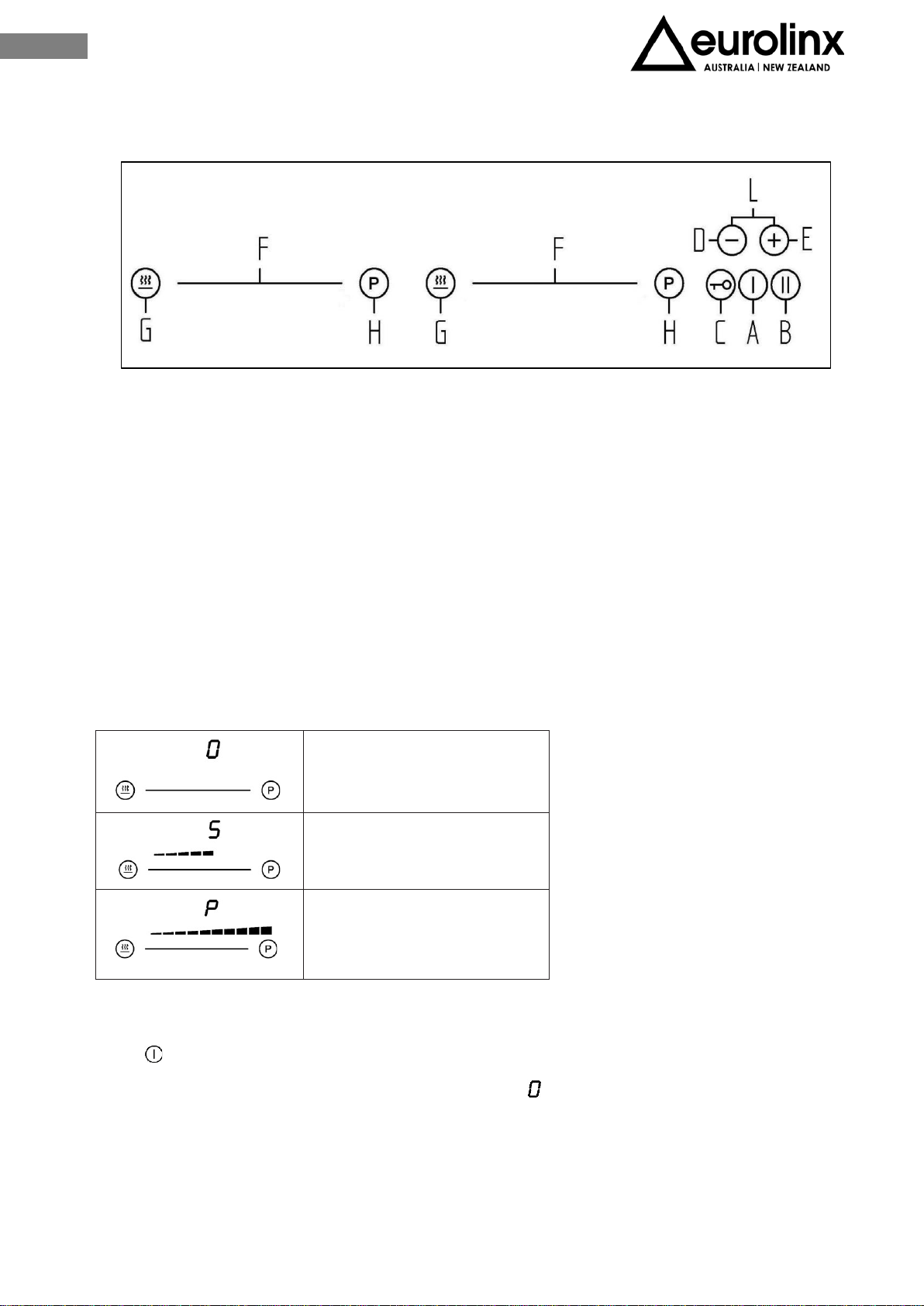
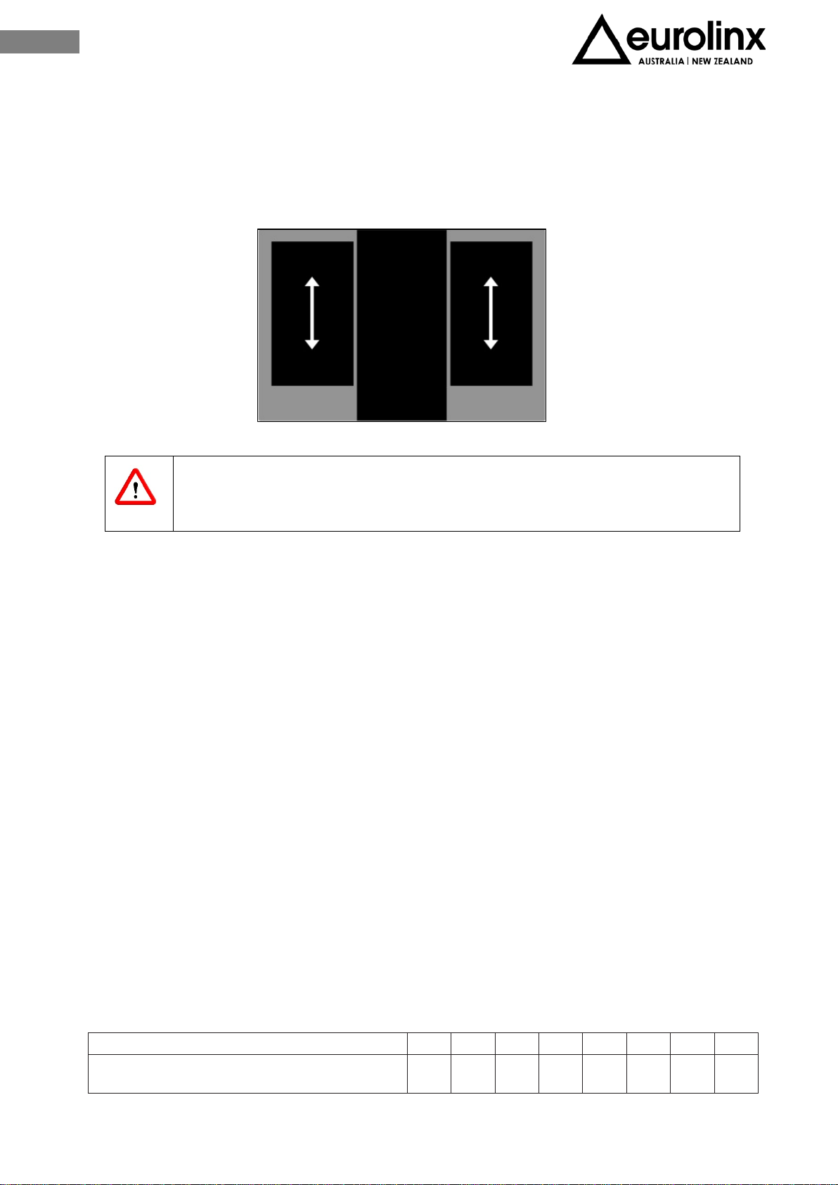
CONTROLS
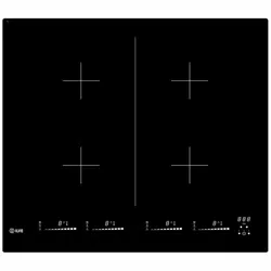
Hob controls are illustrated on Fig.30. Functionality is described hereunder:
A. ON/OFF hob
B. Pause/Recall
C. ON/OFF lock
D. – Timer
E. + Timer
F. Slider
G. Defrost / Heating / Slow cooking
H. Fast cooking
L.Timer
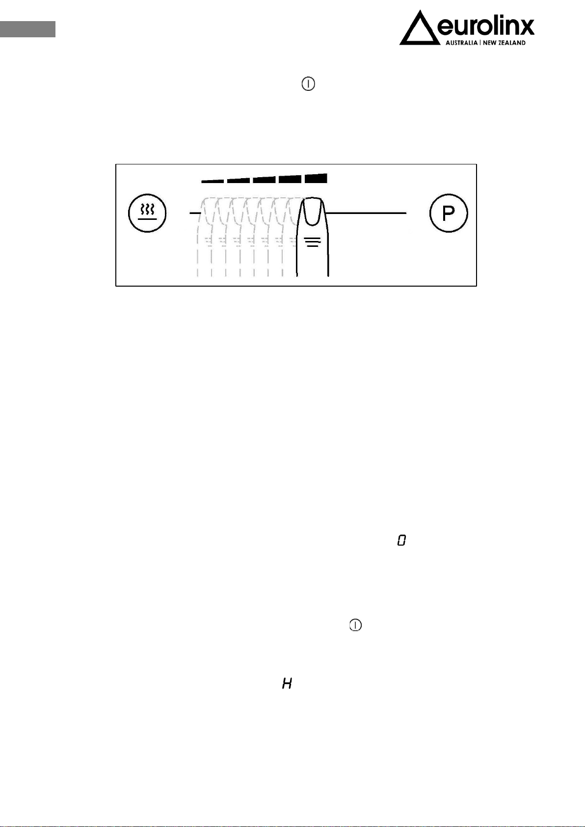
SLIDER FUNCTIONING
0
Medium power
Maximum power
TURN THE HOB ON
Touch for 1 second at least.
The hob is activated. All the powers signals display
The next setting must be done within 20 seconds otherwise the command switches
off.
Fig. 30
53
EN
TURN THE COOKING ZONES ON
After having turned on the hob by touching , within 10 sec switch on the selected
cooking zone touching the related slider.
Use the slider in order to set the desired cooking level from 1 to 9 (Fig. 30) (see section
“COOKING LEVELS)
At the first contact, the level is set according to the part of the slider that is touched. Above
the slider the LEDs light up at the set level.
Sliding with the finger on the slider, you can change the cooking level: to the right the value
increases, to the left it decreases.
When the finger is removed from the slider, the cooking zone starts to heat up according to
the set power.
If you touch, for at least 3 seconds, a precise slider point, the automatic cooking system is
activated (see the chapter "AUTOMATIC FAST HEATING").
TURN THE COOKING ZONE OFF
The selected cooking zone must be active.
Touch the initial part of the slider and bring the displayed value to . A short sound confirms
the switch off.
TURN THE HOB OFF
The induction hob can be switched off anytime by touching
The acoustic signal is switched off and all displays / LEDs are switched off, except those
of the still hot cooking zones that display , indicating the reshidual heat.
54
EN
LOCK FUNCTION
By activating the key Lock you can stop the operation or the use of the cooking zones.
This lock is acting also as Child Lock.
Activation
The hob must be on.
Touch for 1 second at least, the respective LED lights on, the lock is active.
The lock is avoiding any accidental drive, except and
If the hob is turned off while lock function is active this will last until the next switch on.
When the programmed timers end the respective time, the alarms can be turned off by
touching or
without unlocking the control.
Deactivation
The hob must be on.
Touch for 1 second at least, a short sound confirms the deactivation.
CHILD LOCK FUNCTION
By activating the Child Lock protection you can stop the operation of the appliance and
the use of hotplates by children.
This function can only be activated when no cooking zone is selected or active.
Activation
Touch to turn the control on. All displays show .
Within 10 seconds, touch and together. After the sound touch again. All the
displays show
The function is active.
Temporary deactivation for cooking
Touch to turn the control on. All displays show .
Within 10 seconds, touch and together. After the sound touch again .
The cooking zones displays show .
It is possible to set the zones for cooking.
Should the hob be switched off, the functions remains active until the next use.
Deactivation
Touch to turn the control on. All displays show .
Within 10 seconds, touch and together. After the sound signal touch again
The function is not active any more.

55
EN
PAUSE FUNCTION
The execution of the function is only possible if at least one cooking zone is operating.
The pause can also be activated with specific errors of the cooking zones, the error is
hidden; also the indication of residual heat, special messages like , or , are hidden.
The pause has priority. If there is a generic error during the pause, the control will switch
off and the mode will end.
Activation
Touch for 1 second at least, the related LED switches on and all the displays show .
During the function
The timers already programmed before the pause (even the alarm timer) are blocked
during the pause and continue when the function ends.
The automatic heating and the booster function are switched off.
The calculation of residual heat and the limitation of the operating time continue.
The other LED functions (timer, multi-circuit, etc.) continue to be lit according to the
status.
The Function can last max. 10 minutes.
The hob can be switched on or off at any time by touching . In this case the active
pause mode is deactivated.
Deactivation
Touch . The LEDs above the cursor of one of the cooking zones light up.
Within 10 seconds, touch and scroll, from left to right, on the slider of the illuminated area.
The LED above the pause button goes out and the condition before the pause mode is re-
established.
RECALL FUNCTION
Using this function the settings can be saved quickly when, by mistake, the control is
switched off by touching
After switching off, the operator has 6 seconds to turn the control back on and another 6
seconds to touch .
This function can only be used if at least one cooking zone is active (cooking level> 0),
regardless of whether the block function is active or not.
56
EN
RESIDUAL HEAT INDICATOR
The appliance is equipped with the residual heat indicator . The cooking area does not
heat up directly, but through the return heat transmitted by the pot. After the zone is
turned off, the display shows and, as long as it is active, you can use it to heat up
food or defrost food.
When disappears, the cooking area is always hot.
Warning! Danger of burns!
FAST COOKING FUNCTION
Extra powerful setting may be additionally switched on for fast cooking. This extra power
is used for heating large quantities of food.
After switching on, the extra power is activated for 10 minutes then automatically
switches back on to the maximum normal level 9.
When fast cooking is activated, the power of one of the cooking zones is limited. The
display shows the cooking level and the limited power due to fast cooking on the other
cooking zone, alternating for a few seconds.
Activation
Touch on the desired cooking zone
The extra power is active.
The display show the symbol
Deactivation
Touch and scroll on the cursor of the desired cooking zone, until you get to if you want to
turn off the zone or, up to the desired cooking level.
57
EN
POWER MANAGEMENT SYSTEM
The Power Management system distributes power between the available cooking zones
arranged in pairs (Fig.5.3), providing maximum power at a cooking zone and automatically
reducing the power available to the other one. The display of the second cooking zone
alternates, for a few seconds, the power of cooking chosen and the limited power.
Caution! In certain circumstances, the Extra powerful setting
function may turn off automatically to protect the electronic
components inside the hob.
AUTOMATIC FAST HEATING
This function preheats the zone at maximum temperature so as to quickly bring it to the
required temperature. After a defined time (shown in the table below) the cooking level
will return to the previously set level.
It can be activated on each cooking zone, for all cooking levels, except for level 9 where
the power is constantly at maximum.
Activation
Touch for at least 3 sec. any point of the cursor of the selected cooking zone;
In the respective display, for a few seconds, it is displayed alternately with the selected
cooking level, which will be the cooking level to which the zone will operate at the end
of the fast heating;
When the time indicated in the table expires, the function is switched off and goes off.
The automatic cooking system can be switched off at any time by changing the cooking
power level.
LEVEL
1
2
3
4
5
6
7
8
Automatic fast heating
(minutes) 40 72 120 176 256 432 120 192

58
EN
BRIDGE FUNCTION
With this function it is possible to manage two zones with equal size.
The two zones are activated at the same time and controlled only through one of them.
Activation
Whether the two cooking zones operate at a different level, or at level 0, touch at the
same time any point of the related slider;
Now the two zones are operating together, the LED on the right of the related displays
lights on. The display of the control zone shows the set level while the display of the
managed zone shows .
When the function is active, the timer can be set, the LED will light up next to both
displays, and the fast cooking function can’t be set.
If no pot is detected in the final cooking zone within 10 minutes, the bridge function is
automatically deactivated.
Deactivation
Touch any point of the respective sliders of the designated areas at the same time (same
procedure as per activation).
The function is deactivated, the displays of the two cooking zones display and can be
set again.
KEEP WARM FUNCTION
The keep warm function is used to keep the previously cooked food warm and can also be
used as a defrosting or slow cooking function.
Activation
Touch on the desired cooking zone, "defrost" mode is activated; if you touch again
, the "heating" mode is activated;
If you touch for the third time, the "slow cooking" mode is activated; If it is touched again,
the function is deactivated.
59
EN
SAFETY SWITCH OFF
Maximum continuous operation of a particular cooking zone is limited, and the duration is
displayed in the above chart. When the cooking zone is turned off by the safety
mechanism, the indicator displays , or in case there is any remaining heat left.
Level
Time in minutes before
safety switch off
Defrost 480
Keep warm 480
Slow cooking 480
1 516
2 402
3 318
4 258
5 210
6 138
7 138
8 108
9 90
P 10
Example: set the cooking zone to cooking level 5 and let it run for a certain time. If the
cooking level is not changed, after 210 minutes of operation, the safety mechanism will
switch off the cooking zone.
OVERHEATING PROTECTION
The induction hob is also fitted with safety device against overheating which protects
electronic parts from damages. This device operates on several levels. When temperature
of the hotplate excessively rises, it switches on two-stage fan. If this is not enough, extra
powerful heating is deactivated, and finally the safety device either reduces the heating
power of certain hotplates or turns them off completely. When the hotplate cools off, the
full power of hotplate is again available.

60
EN
TIMER FUNCTION
Use of timer facilitates cooking
Activation
• The induction hob and the selected cooking zone must be turned on.
• Touch and at the same time, the timer displays and the symbol of the
first (from the left) active cooking zone lights on.
• Touch and in order to select the zone where you desire to set the timer.
The symbol lights on only on the active cooking zones.
• In 10 seconds from pressing and set the desired cooking time
• The timer value can be displayed:
in minutes and seconds, up to 9min 59sec;
in hours and minutes, up to 9h 59min. In this case the word “min” lights up under
the timer display.
Cooking time can be set independently for each cooking zone.
CHANGING THE PRE-SET COOKING TIME
Cooking time can be changed anytime during the operation:
• Touch and at the same time
• Touch and at the same time as many times as necessary to select the zone
where you wish to change the timer . The selected zone will show the symbol
• Within 10 seconds tuch and to change the time.
Residual cooking time
• The timer will always display the minor residual cooking time (the symbol of the
selected cooking zone is more enlightened than the others );
• Touch and at the same time;
• Touch and as many time as necessary in order to select the cooking zone
where you wish to check the residual cooking time.
The zone will show the symbol lighted;
• The timer will show the residual cooking time.
Deactivation
Once the set operating time has elapsed, the acoustic signal is activated and the cooking
zone switches off. The acoustic signal can be switched off by touching , or turning
off by itself after 2 minutes.
61
EN
Deactivation before the expiration of the set time
• Touch and at the same time
• Touch and as many times as necessary to select the zone where you desire to
deactivate the timer.
• The selected zone will show the symbol ;
• Touch up to reach .
• The symbol of the cooking zone lights off and the timer is deactivated.
ALARM FUNCTION:
The timer can be used as alarm, even when already used for the cooking time.
Activation
When the sensor is switched off:
Touch .
Touch and .
Touch or to set the desired time.
The timer residual time keeps visible even while the hob is switched off.
Deactivation
After the pre-set timing, an acoustic signal switches on at intervals, this can be stopped
touching any sensor or waiting until it self switches off after 2 minutes.
Waning! When the alarm switches off the hob is still on.
Deactivating the alarm before the pre-set time
When the sensor is off:
Touch .
Touch and .
Touch , set the cooking time at .
Simultaneously touch and .
As long as the alarm is on, the timer can be used for any cooking zone.
62
EN
COOKING LEVELS
Heating power of the hotplates may be set at nine different levels. The following chart
indicates illustrative use of each power setting.
LEVEL
PURPOSE
0
Off, using remaining heat
1-2
Keep warm, slow simmer of smaller quantities of food
3
Slow simmer (continuation of cooking after a powerful start
-up).
4-5
Slow cooking
of large quantities of food..
6
Roasting, browning..
7-8
Roasting
9
Start of cooking, roasting.
A
Automatic heating up
P
Fast cooking, for large quantities of food.
ENERGY SAVING TIPS
When buying pots, be careful in selecting size: pot diameter usually refers to the top edge
of the pot, which is often larger than the bottom;
Steam-pressure pots, which use pressure in tightly sealed interior, are especially
economic, and save both time and energy. Shorter cooking time leaves more vitamins in
food;
Always leave enough water in steam-pressure pots, otherwise it may result in overheating
which may damage both the pot and the appliance;
Always cover pots with lids of appropriate size;
Use adequate pot size according with the quantity of food to be prepared.
63
EN
V.4 COOKER HOOD OPERATION
In order to switch the aspiration on firstly open one of the two flaps or both (fig. 5.4)
To open the flap just press on its exterior part (fig. 5.5).
To reach the maximum aspiration try to convert the cooking fumes on the closer side to
the aspiration (Fig. 5.6).
Fig. 5.4
Fig. 5.5
Fig. 5.6
64
EN
Do not place any object above the aesthetic frame and above the flaps of the hood
(Fig.5.7).
The touch controls are located in front of the aspirator and consist of 4 buttons and a
central display (Fig.5.8).
ASPIRATION TURN ON
Touching T1 for 1sec the aspiration turns on at 1st speed.
To increase the speed (2nd – 3rd – 4th or booster) touch T3.
To decrease the speed touch T2 (4th or booster – 3rd – 2nd – 1st).
At the 4th speed (booster) the aspiration will work at the maximum speed for 5 minutes
after that it will automatically switch to 3rd speed. The display will blink “4” for the first
5 minutes than “3” constantly.
ASPIRATION TURN OFF
To turn the hood off touch T1.
Switching off will be possible any speed the aspiration will be working at.
Fig. 5.7
Fig. 5.8

65
EN
ADJUSTABLE AND DELAYED SELF-SWITCHING OFF
By pressing T4 adjustable and delayed self-switching off of the aspiration can be activated.
The display shows “D”:
With the hood in operation, select the desired speed than press T4 to activate the delayed
self – switching off.
The display will show “1” blinking followed by a point, where the point stands for
programming phase.
By pressing T2 and T3 respectively the self-switching off time could be adjusted from 1 to
4:
1= 5 minutes
2= 10 minutes
3= 15 minutes
4= 20 minutes
Press again T4 to confirm the programming.
During self-switching off operation, you can change the set speed by using the T2 and T3
keys and manually switch off the hood by pressing the T1 key.
You can also change the self-switching off time once set by pressing the T4 key again and
resetting the new time: the count will resume from 0.
With the self-switching off activated the display will show cyclically for 5 seconds the set
speed with fix light and for the following 5 seconds the self-switching off setting with
blinking light.
If you choose the intensive speed, after 5min the hood will go to the 3rd speed and the
self-timer will run at the 3rd speed.
With booster set the aspiration will automatically switch to the 3rd speed after 5 minutes,
self- switching off will take place at the 3rd speed.
66
EN
ANTI GREASE FILTER CLEANING ALARM
Every 30 hours’ operation, when aspiration is switched off, letter “G” will light up on the
display for 30 seconds warning that anti grease filter cleaning is necessary.
To reset the timer press T3 for 5 seconds while aspiration is switched off, otherwise the
device will give the same warning the next time aspiration is switched off.
CHARCOAL FILTERS REPLACING ALARM
Every 120 hours’ operation, when the hood is switched off, the display will show “S” for
30 seconds reminding the substitution of the charcoal filters (when installed). To reset
the timer, keep the T3 key pressed for 5 seconds with aspiration switched off, otherwise
the device will give the same warning the next time aspiration is switched off.
The warning will be reported even if the hood is not in filtering mode: in this case proceed
with the ordinary cleaning of the anti-grease filter and reset the warning.
PRESENCE OF LIQUIDS INSIDE THE DEVICE ALARM
The device is equipped with an electronic internal sensor that immediately switches the
aspiration off in case of condensation or excess liquids resulting from accidental fall
through the flaps. The display will show “8” blinking for one minute.
The system is operating even when the device is switched off.
To reset the warning and switch the device on it is absolutely necessary to discharge the
liquids.
CAUTION! Electrically disconnect the mains plug before any service
operation. (fig.1-2 chapter WARNINGS)
To discharge the liquids unscrew the knob (fig.37-X) and open the drain cover.
It is recommended to place the container for collecting liquids at the arrow.
Fig. 5.8
67
EN
To optimize the operation, it is also recommended to dry all the inside of the hood, then
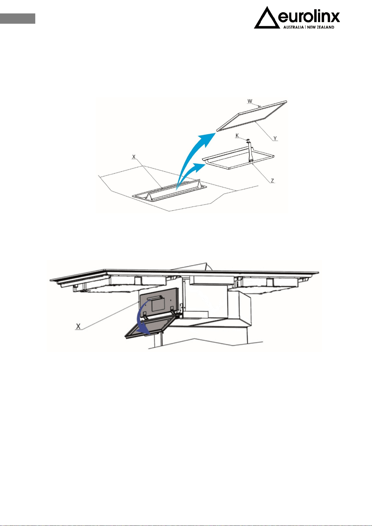
open the right flap (fig.5.9-X) to remove the grease filter in (fig.5.9-Y) by lifting it from
the knob (fig .5.9-W) and grease collector (fig.5.9-Z), lifting it from the knob (fig.5.9-K).
After the above described action open the door on the left of the hood body (Fig. 5.10-X)
and wipe the whole interior thoroughly.
Fig. 5.9
Fig. 5.10
68
EN
V CLEANING AND MAINTENANCE
CAUTION! Before any service or cleaning operation disconnect the
device from the power supply (fig.1-2 chapter WARNINGS).
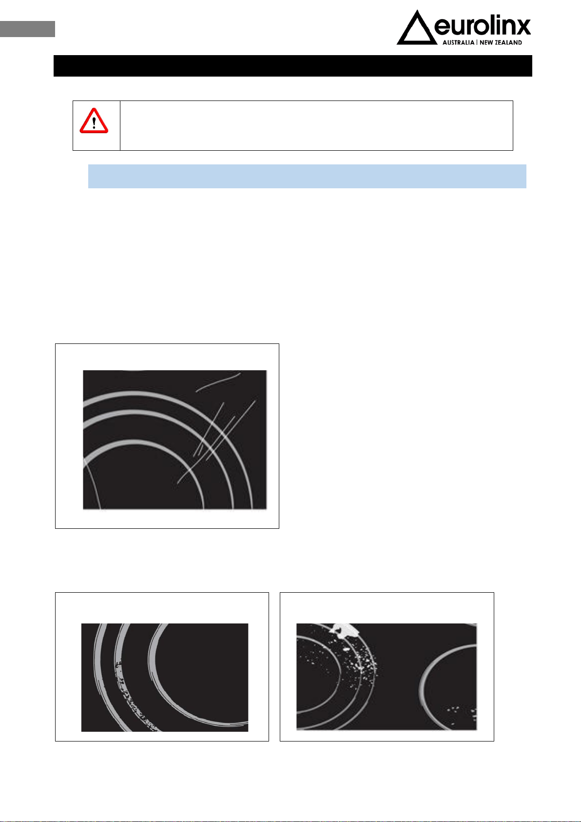
VI.1 INDUCTION HOB CLEANING
After each use of the glass surface, wait for it to cool down and clean it; otherwise, even
the smallest food residue will be burnt onto the hot surface next time you use the
appliance.
For regular cleaning and maintenance of the glass surface, use special conditioning agents
that form a protective layer on the surface, shielding it from dirt.
Before each use wipe any dust or other particles from the surface and pan bottom as these
could scratch the surface (Fig.6.1).
Also abrasive sponges, abrasive detergents, aggressive sprays, decalcification agents can
scratch surface (fig. 6.2 and fig. 6.3).
Fig. 6.1
Fig. 6.2
Fig. 6.3

69
EN
Stubborn and burnt residues can be removed using specific detergents for glass surfaces
or with a scraper! (fig. 6.4).
Caution! Be careful not to get hurt when using the scraper!
The smallest dirt can be removed with a damp sponge.
Warning! Remove the detergent completely from the surface, as some residue may
damage it.
Sugar can permanently damage the glass surface, sugar should be removed immediately
with the scraper, even if the glass is still hot (see figure 43 above).
Glass screen printing could be damaged by the use of aggressive detergents, steel sponges,
dirt pan bottom.
Any change in the colour of the glass surface does not affect the working or the stability
of the surface, but it is caused by the use of copper or aluminium pots or food residues
on the bottom of the pots.
Warning! All defects mentioned above are of aesthetic character and do not directly
affect the operation of the appliance. These cannot be repaired under guarantee.
Fig. 6.4

70
EN
VI.2 COOKER HOOD CLEANING
The hood must be cleaned immediately after installing and removing the protective film
in order to remove any residual glue or impurities of any kind.
The hood must be cleaned frequently both internally and externally (at least once a
month).
Do not allow dirt to accumulate on the outer and inner surfaces of the hood.
The following products can be used for the aesthetic part of the hood in polished black
stainless steel:
Nitro Solvent
Liquid detergents or glass cleaning products;
Neutral liquid soap (in case of greasy dirt);
Soft cloths (to be used with movements following the direction of finishing and not
transversely to the same or circulatory).
Warning! Products that are NOT to be used are:
Products containing chlorides, especially those containing hydrochloric acid;
Halide based products;
Hydrogen peroxide products;
Hypochlorous acid-based bleaches;
Acid-containing aggressive products;
Detergents containing abrasive powder;
Silver cleaning products;
Detergents whose chemical composition is unknown;
Abrasive wipes, brushes or disc;
Coarse cloths or rough paper;
Tools that have previously cleaned other metals or alloys.
Cleaning at first use
After removing the protective plastic film, in the presence of any stains or spots, first
wash with nitro solvent followed by further washing with neutral soap or liquid detergent,
using only soft cloths and performing movements following the direction of finishing and
not in a circulatory or transversal direction.
Ordinary cleaning
Ordinary cleaning should be performed before excessive build-up of dirt can occur which
can cause abrasive phenomena.

71
EN
Before performing the washing operations, any dust particles should be removed by air or
aspirated, so as to avoid rubbing on the surface.
Where water has been used as a means of cleaning or rinsing, especially in areas with
significant limestone, it is recommended to dry the surface to prevent staining.
To avoid contamination caused by iron particles, make sure that the tools selected for
cleaning have not previously been used on other metals or alloys.
Materials for cleaning stainless steel products must be exclusively reserved for this
purpose.
Special attention should be paid to the grease filter, which has the function of retaining
the fat particles contained in the vapors, and the lump, which has the function of
collecting the fat that could fall from the grease filter. Both of these items should be
washed when the relevant warning appears or at least once a month in hot water and
detergent (even in dishwasher).
The filter may become discolored after washing. This is normal and does not mean it needs
to be replaced.
To carry out the maintenance of the antifreeze and damp filter, it is essential to remove
them from the hood.
To remove the metallic grease filter and the drip tray, proceed as shown in Figure 46 of
the NOTICE LIQUID INSIDE THE HOOD - chapter OPERATION. The operation must be carried
out both on the right flap and on the left flap.
The activated charcoal filter, if present, should not be washed but replaced when the
relevant warning appears (see ACTIVE CARBON FILTER REPLACEMENT) or at least 3-4 times
a year.
Ask for the filter to the manufacturer.
To replace the active charcoal filter, check the instruction manual of the kit separately
purchased.
72
EN
VI TROUBLESHOOTING GUIDE
WARNING! During the warranty period repairs can only be carried out by authorized
service staff.
CAUTION!
Before any service or maintenance, disconnect the power supply of
the device (fig.1-2 chapter WARNINGS)
Unauthorized repairs or services may cause electric shock or short circuit, so do not
run them. Leave these jobs to authorized personnel only.
In the case of minor disturbances, try to solve the problem by following the
instructions in the operating instructions.
Elimination of faults or complaints caused by improper use or installation of the
appliance will not be warranted. The repair costs will be borne by the user.
ERROR CODE ERROR DESCRIPTION GUIDE
E03 +
Continuous
sound, or
O Er03
Continuous activation of the sensors
for more than 10 seconds, caused by
the presence of objects or liquids on
the glass in the control area.
Remove objects and/or liquids + clean the glass.
If the problem persists get in touch with the authorized
service center quoting the error code.
E21
The control switches off due to
overtemperature to prevent damage
to the electronics.
Get in touch with the authorized service
center quoting the error code.
tecnica
E22 o Er22
Error of the command sensors.
The command switches off after 3.5-
7.5 seconds. In one or more sensors
the detection threshold is incorrect.
Get in touch with the authorized service
center quoting the error code.
tecnica
E20 o Er20
Microcontroller memory anomaly.
Get in touch with the authorized service
center quoting the error code.
tecnica
E36 o Er36
Short circuit in the command
temperature sensor.
Get in touch with the authorized service
center quoting the error code.
tecnica
E31 o Er31
Anomaly in the configuration of the
cooking zones.
Get in touch with the authorized service
center quoting the error code.
tecnica
E47 o Er47
Abnormal communication between
the control and one or more cooking
zones.
Get in touch with the authorized service center
quoting the error code.
tecnica

73
EN
E2
Overheating in the coils of one or
more cooking zones, for incorrect
use of the hob or for failure of the
cooling fan.
Get in touch with the authorized service
center quoting the error code.
tecnica
EA
Power board error.
Fault component.
Get in touch with the authorized service
center quoting the error code.
tecnica
U400
The command switches off after 1
second and
emits a continuous
acoustic signal. This may be due to:
1) Supply of high voltage
2) Error connecting the hob to the
mains supply.
1) Contattare il centro di assistenza tecnica
autorizzato, specificando il codice di errore
2) Contattare un elettricista per verifica della
rete domestica.
E5
Fault of the power board filter.
Get in touch with the authorized service center quoting
the error code.
E6 Anomaly of the power board
Get in touch with the authorized service center quoting
the error code.
E8
Incorrect fan speed.
Error of the left or right fan.
Aria di scarico bloccata, ad esempio da carta.
Get in touch with the authorized service center quoting
the error code.
E9
Defect of the temperature sensor of a
cooking zone.
Get in touch with the authorized service center quoting
the error code.
74
EN
VII DISCONTINUATION, DISASSEMBLY AND WASTE DISPOSAL
DISCONTINUATION
Discontinuation means the definitive stop of the operation and the disassembly or
the appliance.
After discontinuation the appliance can be installed on another furniture, privately
resold or disposed of.
CAUTION!
For discontinuation it is necessary to switch the appliance off and
disconnect the power (fig. 1-2 chapter WARNINGS).
CAUTION!
Electrical disconnection and must be undertaken only by qualified
service staff.
DISASSEMBLY
Disassembly requires that the appliance is accessible for disassembly and has been
disconnected from the power supply.
To do so, you need:
Loose screws and fixing brackets
Remove any silicone seals
Disconnect the motor and the channel from the hob
Take the top of the hob out.
WASTE DISPOSAL
This appliance is marked in accordance with the European Directive
2012/19/EC,
Waste Electrical and Electronic Equipment (WEEE).
The symbol on the product or on the packaging indicates that the
product should not be considered as a normal household waste, but
must be taken to the appropriate collection point for the recycling of
electrical and electronic equipment.
By appropriately dispose of this product, it helps to avoid potential
negative consequences for the environment and health that may result
from inappropriate disposal of the product.
For more detailed information on recycling this product, contact your
local office, local waste disposal service, or the shop where you
purchased the product.

75
EN

76
EN