Loading ...
Loading ...
Loading ...
27
W415-1678 / 08.09.16
EN
4.2 USING FLEXIBLE VENT COMPONENTS
For safe and proper operation of the appliance, follow the venting
instructions exactly.
All inner fl ex pipe and outer fl ex pipe joints may be sealed using high
temperature red RTV silicone W573-0002 (not supplied) or the high
temperature sealant W573-0007 Mill Pac (not supplied). However, the high
temperature sealant W573-0007 Mill Pac (not supplied) must be used on
the joint connecting the inner fl ex pipe and the exhaust fl ue collar.
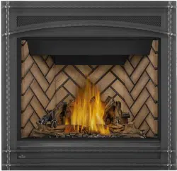
Use only approved fl exible vent pipe kits marked:
“Wolf Steel Approved Venting” as identifi ed by
the stamp only on the outer fl ex pipe.
22.1A
ELBOW
SPACERS
DO NOT ALLOW THE INNER FLEX PIPE TO BUNCH UP ON HORIZONTAL OR VERTICAL RUNS AND ELBOWS.
KEEP IT PULLED TIGHT.
SPACERS ARE ATTACHED TO THE INNER FLEX PIPE AT PREDETERMINED INTERVALS TO MAINTAIN AN EVEN
AIR GAP TO THE OUTER FLEX PIPE. THIS GAP IS REQUIRED FOR SAFE OPERATION. A SPACER IS REQUIRED
AT THE START, MIDDLE AND END OF EACH ELBOW TO ENSURE THIS GAP IS MAINTAINED. THESE SPACERS
MUST NOT BE REMOVED.
!
WARNING
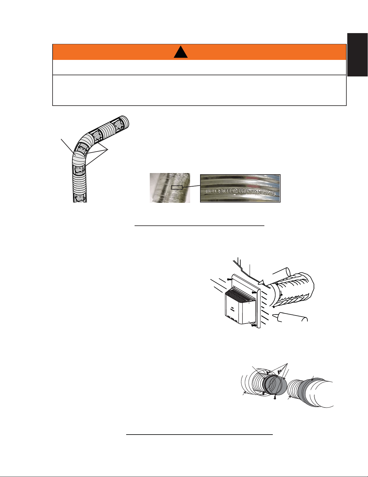
4.2.1 HORIZONTAL AIR TERMINAL INSTALLATION
A
. Stretch the inner fl ex pipe to the required length taking into
account the additional length needed for the fi nished wall
surface. Apply a heavy bead of the Mill Pac sealant
(W573-0007) (not supplied) to the inner sleeve of
the air terminal. Slip the vent pipe a minimum of 2”
(50.8mm) over the inner sleeve of the air terminal and
secure with a minimum of 3 #8 screws.
B. Using the outer fl ex pipe, slide over the outer
combustion air sleeve of the air terminal and secure with
a minimum of 3 #8 screws. Seal using red RTV silicone
(W573-0002) (not supplied).
C. Insert the vent pipes through the fi restop maintaining the
required clearance to combustibles. Holding the air terminal
(lettering in an upright, readable position), secure to the
exterior wall and make weather tight by sealing with
caulking (not supplied).
D. If more vent pipe needs to be used to reach the fi replace,
couple them together as illustrated. The vent system must
be supported approximately every 3 feet (0.9m) for both
vertical and horizontal runs. Use noncombustible strapping
to maintain the minimum clearance to combustibles.
The air terminal mounting plate may be recessed into the exterior wall or siding no greater than the depth
of its return fl ange.
23.1C
SCREWS
#10x2"
2" (50.8mm) OVERLAP
OUTER FLEX PIPE
INNER FLEX
PIPE
HIGH TEMPERATURE
SEALANT
CAULKING
HI-TEMP
SEALANT
#8 X 1/2” SELF DRILLING
SCREWS
INNER COUPLER
OUTER COUPLER
OUTER
FLEX PIPE
INNER
FLEX PIPE
OUTER
FLEX PIPE
Loading ...
Loading ...
Loading ...