Loading ...
Loading ...
Loading ...
Operation
16 Owner’s Manual for 60 Hz Air-Cooled Generators
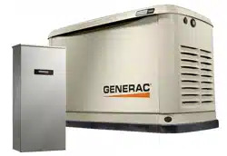
NOTE: Always lift front access panel straight up before
pulling away from enclosure (B and C). Do not pull panel
away from the enclosure before lifting up (D).
Intake Side Panel Removal
See
Figure 3-3. Intake side panel (A) must be removed
to access battery compartment, fuel regulator, and sedi-
ment trap.
1. Raise lid and remove front panel.
2. Use a hex key to remove two mounting screws (B)
and L-bracket screw (C).
3. Lift intake panel up and away from generator.
NOTE: Always lift intake side panel straight up before
pulling away from enclosure. Do not pull panel away from
enclosure before lifting up (D).
Figure 3-3. Intake Side Panel Removal
Main Line Circuit Breaker (Generator
Disconnect)
See
Figure 3-4. This is a 2-pole main line circuit breaker
(MLCB) (generator disconnect) (A) rated according to rel-
evant specifications.
The generator MLCB (generator disconnect) can be
locked in OFF (OPEN) for security. Use an appropriately-
sized padlock (not included) with a shackle long enough
to pass through both lock tabs (B).
Figure 3-4. Main Line Circuit Breaker (MLCB)
NOTE: DO NOT leave generator MLCB (generator dis-
connect) locked in OFF (OPEN) during normal generator
operation. Leaving generator MLCB (generator discon-
nect) in OFF (OPEN) will prevent generator from power-
ing structure during a power outage when placed in
AUTO mode.
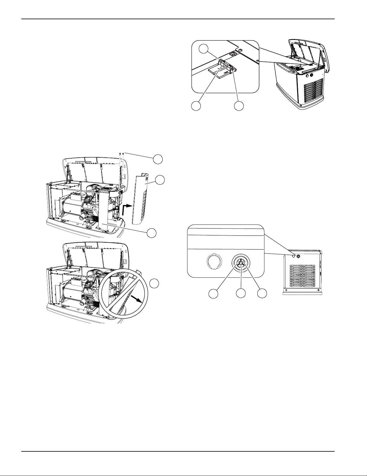
LED Indicator Lights
See
Figure 3-5. Three LEDs are visible behind a translu-
cent lens on the generator side panel. These LEDs indi-
cate generator operating status.
Figure 3-5. LED Indicator Lights
• Green LED “Ready” light (A) illuminates when util-
ity is present and control panel is in AUTO. LED
flashes when automatic transfer switch converts to
generator power during a utility power outage.
• Red LED “Alarm” light (B) illuminates when gener-
ator is OFF or a fault is detected. Contact an IASD.
• Yellow LED “Non-Critical Alert” light (C) illuminates
when maintenance is required.
NOTE: Yellow LED may be illuminated at the same time
as either the red or green LED.
002961
D
B
A
C
001810
B
A
B
001791
A
C
B
Loading ...
Loading ...
Loading ...