Loading ...
Loading ...
Loading ...
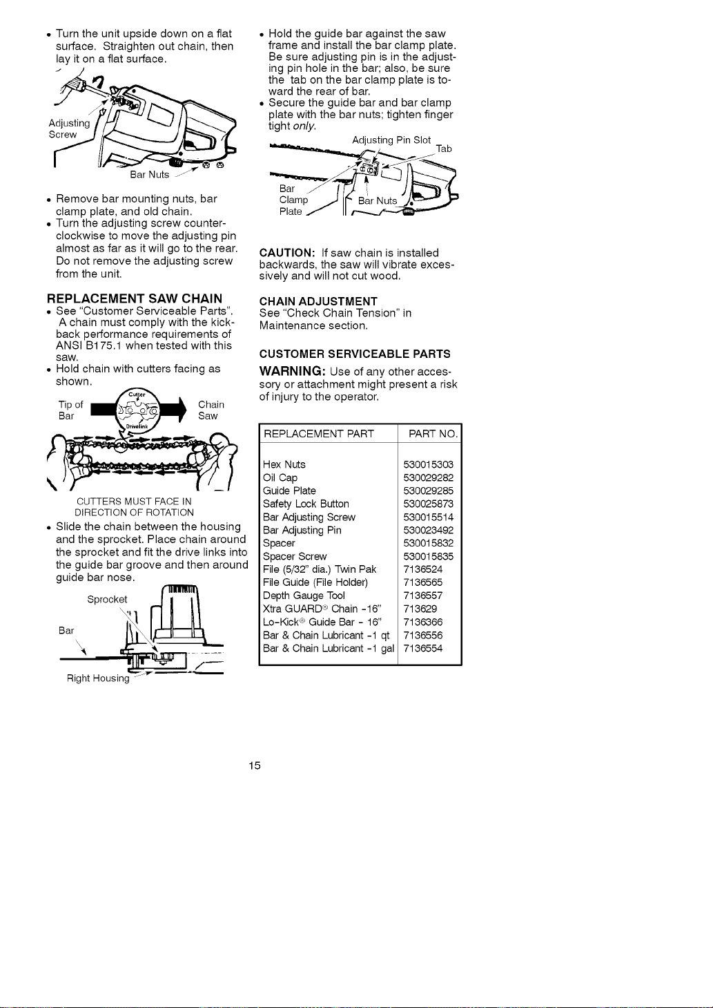
• Turntheunitupsidedownonaflat
surface.Straightenoutchain,then
layitonaflatsurface.
J
Screw
Bar Nuts l-
• Remove bar mounting nuts, bar
clamp plate, and old chain.
• Turn the adjusting screw counter-
clockwise to move the adjusting pin
almost as far as it will go to the rear.
Do not remove the adjusting screw
from the unit.
REPLACEMENT SAW CHAIN
• See "Customer Serviceable Parts".
A chain must comply with the kick-
back performance requirements of
ANSI B175.1 when tested with this
saw,
• Hold chain with cutters facing as
shown.
Tip of Chain
Bar Saw
\
CUTTERS MUST FACE IN
DIRECTION OFROTATION
• Slide the chain between the housing
and the sprocket. Place chain around
the sprocket and fit the drive links into
the guide bar groove and then around
guide bar nose.
Sprocket
Bar \_
Right Housing --
• Hold the guide bar against the saw
frame and install the bar clamp plate.
Be sure adjusting pin is in the adjust-
ing pin hole in the bar; also, be sure
the tab on the bar clamp plate is to-
ward the rear of bar.
• Secure the guide bar and bar clamp
plate with the bar nuts; tighten finger
tight only.
Adjusting Pin Slot
__,_,_jj _ Tab
Bar fF2
Clamp J If" BarNuts_/._'"_ ''
Plate / II
CAUTION: If saw chain is installed
backwards, the saw will vibrate exces-
sively and will not cut wood.
CHAIN ADJUSTMENT
See "Check Chain Tension" in
Maintenance section.
CUSTOMER SERVICEABLE PARTS
WARNING: Use of any other acces-
sory or attachment might present a risk
of injury to the operator.
REPLACEMENT PART PART NO.
Hex Nuts
Oil Cap
Guide Plate
Safety Lock Button
Bar Adjusting Screw
Bar Adjusting Pin
Spacer
Spacer Screw
File (5/32" dia.) Twin Pak
File Guide (File Holder)
Depth Gauge Tool
Xtra GUARD _ Chain -16"
Lo-Kick <_Guide Bar - 16"
Bar & Chain Lubricant -1 qt
Bar & Chain Lubricant -1 gal
530015303
530029282
530029285
530025873
530015514
530023492
530015832
530015835
7136524
7136565
7136557
713629
7136366
7136556
7136554
15
Loading ...
Loading ...
Loading ...